US6433777B1 - Apparatus for extending a cursor control stick - Google Patents
Apparatus for extending a cursor control stickDownload PDFInfo
- Publication number
- US6433777B1 US6433777B1US09/408,995US40899599AUS6433777B1US 6433777 B1US6433777 B1US 6433777B1US 40899599 AUS40899599 AUS 40899599AUS 6433777 B1US6433777 B1US 6433777B1
- Authority
- US
- United States
- Prior art keywords
- extension
- joystick
- extension member
- cursor control
- mounting post
- Prior art date
- Legal status (The legal status is an assumption and is not a legal conclusion. Google has not performed a legal analysis and makes no representation as to the accuracy of the status listed.)
- Expired - Fee Related
Links
Images


Classifications
- G—PHYSICS
- G06—COMPUTING OR CALCULATING; COUNTING
- G06F—ELECTRIC DIGITAL DATA PROCESSING
- G06F1/00—Details not covered by groups G06F3/00 - G06F13/00 and G06F21/00
- G06F1/16—Constructional details or arrangements
- G06F1/1613—Constructional details or arrangements for portable computers
- G06F1/1615—Constructional details or arrangements for portable computers with several enclosures having relative motions, each enclosure supporting at least one I/O or computing function
- G06F1/1616—Constructional details or arrangements for portable computers with several enclosures having relative motions, each enclosure supporting at least one I/O or computing function with folding flat displays, e.g. laptop computers or notebooks having a clamshell configuration, with body parts pivoting to an open position around an axis parallel to the plane they define in closed position
- G—PHYSICS
- G06—COMPUTING OR CALCULATING; COUNTING
- G06F—ELECTRIC DIGITAL DATA PROCESSING
- G06F1/00—Details not covered by groups G06F3/00 - G06F13/00 and G06F21/00
- G06F1/16—Constructional details or arrangements
- G06F1/1613—Constructional details or arrangements for portable computers
- G06F1/1633—Constructional details or arrangements of portable computers not specific to the type of enclosures covered by groups G06F1/1615 - G06F1/1626
- G06F1/1684—Constructional details or arrangements related to integrated I/O peripherals not covered by groups G06F1/1635 - G06F1/1675
- G06F1/169—Constructional details or arrangements related to integrated I/O peripherals not covered by groups G06F1/1635 - G06F1/1675 the I/O peripheral being an integrated pointing device, e.g. trackball in the palm rest area, mini-joystick integrated between keyboard keys, touch pads or touch stripes
Definitions
- the present inventionrelates generally to computers employing cursor control sticks, and more specifically to apparatus for extending a cursor control stick to provide a joystick.
- Computersparticularly portable computers such as laptop or notebook computers often comprise cursor control sticks that allow users to manipulate the location of a cursor or pointer on the computer's display.
- cursor control stickswhich are more commonly known by trade names such as Panastick, Glidestick, or EZ Point®, typically include a mounting post positioned among the keys of the computer's keyboard in a position conveniently reached by the user while typing (e.g., between the “G”, “H”, and “B” keys of the keyboard).
- a small rubberized capis positioned on the neck of the mounting post.
- This cursor control stick capmay have a roughened surface so that the cursor control stick may be more easily manipulated by the user's fingertip.
- Miniature force sensing devicessuch as strain gauges or pressure sensitive resistive material sense lateral motion of the mounting post. This motion is then translated into a corresponding movement of the cursor on the computer's display.
- cursor control sticksalso allow a user to select a point on the computer display by applying a downward force on the cursor control stick cap.
- An example of such a cursor control stickis disclosed in U.S. Pat. No. 5,712,660 to Martin.
- Such cursor control stickstypically utilize multiple piece mounting posts and force sensing devices to sense both lateral and downward motion of the mounting post.
- the cursor control sticks utilized by such computerscan not extend substantially above their keyboards.
- the sides of the cursor control stick gripcannot be easily grasped by a user. Instead, friction between the user's fingertip and the top surface of the grip is relied upon for imparting lateral motion to the cursor control stick. While this configuration is sufficient for most cursor control operations, certain specialized applications, in particular computer gaming applications, require rapid movement of indicia throughout the two-dimensional plane of the computer's display. Similarly, many users desire finer control of the cursor than can be provided by a conventional cursor control stick.
- joystick controllersare not easily implemented in portable computers, and have, in the past, been provided as external peripheral components operably coupled to the portable computer via a cable.
- the present inventionis directed to novel apparatus for extending a cursor control stick to provide a joystick for a portable computer such as a notebook or laptop computer.
- a joystick extension for a cursor control stickWhen assembled the joystick extension extends the cursor control stick converting it into a joystick.
- the joystick extensionis comprised of an extension member having a mounting post attachment portion disposed in a first or lower end and a grip attachment portion disposed in a second or upper end.
- the mounting post attachment portionattaches the extension member to the mounting post of the cursor control stick.
- the grip attachment portionprovides attachment of a grip such as the cursor control stick cap.
- the grip attachment portionmay also emulate the mounting post of the cursor control stick to provide attachment of a second extension member. In this manner, a plurality of extension members may be attached end to end to provide a longer joystick with greater leverage. Adjustment of joystick height may be accomplished by varying the number of extension members utilized.
- a telescoping joystick extension for a cursor control stickis disclosed.
- the telescoping joystick extensionis comprised of a telescoping extension member including one or more segments that may be alternately extended to provide a joystick controller device and retracted to provide a conventional cursor control stick.
- the telescoping extension memberincludes a mounting post attachment portion providing attachment of the telescoping extension member to the mounting post and a grip attachment portion for attachment of a grip.
- the cursor control stick grip or capmay be used as the grip of the joystick extension.
- the present inventionprovides for storage and use of the cap while the extension member is attached to the mounting post.
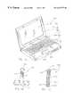
- FIG. 1Ais an isometric view of a portable computer employing a joystick extension for a cursor control stick in accordance with a first exemplary embodiment of the present invention
- FIG. 1Bis a side elevational view of the joystick extension shown in FIG. 1A;
- FIG. 1Cis a cross-sectional side elevational view of the cursor control stick shown in FIG. 1A;
- FIG. 2Ais an isometric view of a portable computer employing a joystick extension having multiple extension members in accordance with a second exemplary embodiment of the present invention
- FIG. 2Bis a side elevational view of the joystick extension shown in FIG. 2A;
- FIG. 2Cis a cross-sectional side elevational view of the joystick extension shown in FIG. 2A;
- FIG. 3Ais an isometric view of a portable computer having a telescoping joystick extension in accordance with a second embodiment of the present invention
- FIG. 3Bis a side elevational view of the joystick extension shown in FIG. 3A, illustrated in the collapsed position;
- FIG. 3Cis a side elevational view of the joystick extension shown in FIG. 3A, illustrated in the extended position;
- FIG. 3Dis a cross-sectional side elevational view of the joystick extension shown in FIG. 3A, further illustrating an exemplary extension and retraction mechanism holding the joystick extension in the extended position;
- FIG. 3Eis a cross-sectional side elevational view of the joystick extension shown in FIG. 3A, further illustrating an exemplary extension and retraction mechanism holding the joystick extension in the collapsed position;
- FIG. 3Fis a cross-sectional side elevational view of the joystick extension shown in FIG. 3A, further illustrating an alternative extension and retraction mechanism;
- FIG. 4Ais an isometric view of a portable computer having a telescoping joystick extension in accordance with a second embodiment of the present invention
- FIG. 4Bis a side elevational view of the joystick extension shown in FIG. 4A, illustrated in the collapsed position;
- FIG. 4Cis a side elevational view of the joystick extension shown in FIG. 4A, illustrated in the extended position;
- FIG. 4Dis a cross-sectional side elevational view of the joystick extension shown in FIG. 4A, illustrated in the extended position;
- FIG. 4Eis a cross-sectional side elevational view of an alternative embodiment of the joystick extension shown in FIG. 4A wherein the extension member is permanently attached to the mounting post;
- FIG. 5is a side elevational view of the portable computer illustrating retraction of the telescoping extension members of the present invention as the lid of the computer is folded against the keyboard.
- the present inventionis directed to a joystick extension for cursor control sticks commonly utilized by portable computers such as laptop or notebook computers.
- the present inventionthus provides portable computer users with an easy-to-use joystick for precise cursor control and/or gaming applications which does not require the use of any of the portable computer's external device ports, and which does not take up any more keyboard space than present cursor control sticks.
- the joystick extension of the present inventionallows for adjustment of joystick height, and provides for storage and use of the cursor control stick cap during joystick use. Accordingly, reference will now be made in detail to the presently preferred embodiments of the invention, examples of which are illustrated in the accompanying drawings.
- Portable computer 100is comprised of a processor portion 112 having a keyboard 116 , and a lid portion 114 including a display 118 .
- the lid portion 114is pivotally hinged to the processor portion 112 so that the lid portion 114 and processor portion 112 may be folded together for storage and transport of the computer 100 .
- display 118is held in an orientation generally adjacent and parallel to keyboard 116 . This orientation helps to protect the display 118 , typically a liquid crystal display (LCD), from damage while the computer 100 is being transported or stored.
- LCDliquid crystal display
- a cursor control stick 120is shown positioned among the keys of keyboard 116 so that it may be conveniently manipulated by a user of the portable computer 100 .
- Controlssuch as buttons 124 & 126 positioned adjacent to the keyboard 116 , emulate the buttons of a conventional computer mouse to provide user input for software employing a graphical user interface (GUI).
- GUIgraphical user interface
- the cursor control stick 120 and buttons 124 & 126may be used to accomplish such actions as “pressing” or “clicking” on-screen “buttons” in dialog boxes, choosing menu items, or the like.
- Cursor control stick 120is comprised of a mounting post 128 extending upwardly through an opening formed between keys of keyboard 116 .
- a small grip or cap 122is mounted to mounting post 128 .
- This cap 122is usually fabricated of rubber or a rubberized material, and may have a textured surface so that it does not slip against the user's fingertip when the cursor control stick 120 is manipulated by the user.
- the cursor control stick cap 122may be removed from mounting post 128 so that it may be replaced when damaged or worn.
- Miniature force sensing apparatussuch as strain gauges or pressure sensitive resistive material (not shown) sense lateral motion imparted to mounting post 128 as the cursor control stick 120 is manipulated by a user. This motion is translated into a corresponding movement of the cursor on display 118 .
- the cursor control stick 120may also allow the user to select a point on the display 118 by applying a downward force on cursor control stick cap 122 .
- An example of such a cursor control stickis described in U.S. Pat. No. 5,712,660, which is herein incorporated by reference in its entirety.
- cursor control stick 120is shown positioned between the “G”, “H”, and “B” keys of keyboard 116 .
- This locationwhich is near the home typing row, is advantageous because it allows a user to conveniently manipulate the cursor control stick 120 using the index finger of either hand from a normal typing position.
- cursor control stick 120may alternately be positioned elsewhere within keyboard 116 , or mounted to the processor portion 112 or lid portion 114 of portable computer 100 without departing from the scope and spirit of the present invention.
- the joystick extension 200is comprised of an extension member 212 which may be attached to the mounting post 128 of cursor control stick 120 .
- extension member 212has an elongate, cylindrical shape, and is fabricated from a rigid material such as a hard plastic, a metal, or a composite.
- a textured gripping surface 222may be formed (e.g., cut, stamped, knurled, etc.) in the surface of extension member 212 .
- a textured gripping surface 222may be provided which is comprised of a resilient material co-molded or otherwise adhered to the surface of the extension member 212 (not shown).
- the base of extension member 212includes a mounting post attachment portion 214 for securing the joystick extension 200 to cursor control stick 120 .
- the mounting post attachment portion 214includes an aperture 218 sized and shaped to fit securely onto mounting post 128 .
- the mounting posts of conventional cursor control sticksoften have a polygonal (e.g., square, triangular, pentagonal, hexagonal, etc.) shape to prevent rotation of the cursor control stick cap 122 during use.
- aperture 218would have the same polygonal shape as the mounting post and would be sized to fit tightly thereon.
- aperture 218may be lined with a rubberized material or textured (not shown) to provide a more secure attachment to mounting post 128 .
- a grip attachment portion 216is disposed at the upper end of the extension member 212 for the attachment of a grip.
- the grip attachment portion 216includes a neck 220 which is identical in size and shape to mounting post 128 (e.g., polygonal) so that the cap 122 of cursor control stick 120 may be utilized as the grip.
- This configurationprovides many advantages.
- the cursor control stick cap 122provides a textured gripping surface at the end of joystick extension 200 .
- grip attachment portion 216provides a natural storage/usage position for the cursor control stick cap 122 while joystick extension 200 is being utilized.
- cursor control stick cap 122being made of a soft rubberized material, would minimize damage to the computer's display 118 .
- a specialized gripmay be provided (not shown).
- Such a gripmay be shaped and sized to fulfill the unique needs of a user.
- a joystick extension 200 having an enlarged, ergonomically shaped gripmay be provided for a disabled or arthritic user whose hands lack the dexterity to manipulate a conventional cursor control stick.
- joystick extension 200may be comprised of a single extension member 212 .
- two or more extension members 212may be stacked together to provide a taller joystick extension 200 having greater leverage. It will be appreciated that the number of extension members 212 stacked on top of each other may be varied so that joystick height may be incrementally adjusted.
- a userto install and use the joystick extension 200 , first removes the cursor control stick cap 122 from mounting post 128 .
- One or more extension members 212are then placed (stacked) onto the cursor control stick 120 by inserting mounting post 128 (or neck 220 ) into the aperture 218 of mounting post attachment portion 214 of each extension member 212 .
- the cursor control stick cap 122is to be utilized as the joystick grip, it is then placed onto the grip attachment portion 216 of the uppermost extension member 212 .
- the useronly has to remove cursor control stick cap 122 from the joystick extension 200 , remove the extension member(s) 212 from mounting post 128 , and remount the cap 122 onto mounting post 128 .
- the extension member(s) 212may then be stored for later use.
- joystick extensions 300in accordance with a second exemplary embodiment of the invention are shown.
- Joystick extensions 300are comprised of a telescoping extension member 312 having first and second segments 314 & 316 .
- the second segment 316may be slidably disposed within first segment 314 so that it may be extended and retracted between a collapsed position wherein the extension member 312 functions as a conventional cursor control stick (FIG. 3 B), and an extended position wherein the telescoping extension member 312 is suitable for use as a joystick (FIG. 3 C).
- First segment 314is attached to the cursor control stick mounting post 128 via mounting post attachment portion 318 disposed at its lower end. As shown in FIGS. 3D and 3E, this attachment may be impermanent, allowing the telescoping extension member 312 to be removed and replaced by the cursor control stick cap 122 .
- mounting post attachment portion 318includes an aperture 320 sized and shaped to fit securely onto the mounting post 128 of cursor control stick 120 .
- mounting post attachment portion 318may provide an attachment that is substantially permanent. For instance, as shown, a shaped mounting post 130 may engage aperture 320 so as to retain first segment 314 .
- first segment 314could be adhered to mounting post 128 or the mounting post 128 and first segment 314 could be integrally molded as a single component.
- a gripmay be mounted to the upper end of the second segment 316 via grip attachment portion 322 .
- the gripmay be a conventional cursor control stick cap 122 .
- the grip attachment portion 322may include a neck 324 which is identical in size and shape to the mounting post 128 (e.g., polygonal, round, elliptical, etc.) of cursor control stick 120 .
- the cursor control stick cap 122would be placed onto the neck 324 and utilized as the grip of joystick extension 300 .
- utilization of the cursor control stick cap 122 as the grip of the joystick extension 300provides several advantages.
- the grip attachment portion 322provides a natural storage/usage position for the cursor control stick cap 122 while the joystick extension 300 is being utilized.
- the cursor control stick cap 122being made of a soft rubberized material, would minimize damage to the computer's display 118 should the joystick extension 300 be inadvertently left in the extended position when the lid portion 114 is closed.
- a spring biased extension and retraction mechanism 326may be provided for moving the second segment 316 between the collapsed position, shown in FIG. 3E, and the extended position, shown in FIG. 3 D.
- Extension and retraction mechanism 326comprises a helical compression spring 328 for providing a generally upward force (with respect to the processor portion 112 of computer 100 ) tending to move the second segment 316 to the extended position (FIGS. 3 C and 3 E).
- Extension and retraction mechanismfurther comprises a latching mechanism 330 for retaining the second segment 316 in the collapsed position against the upward force exerted by spring 328 .
- the latching mechanism 330allows the joystick extension 300 to be utilized as a conventional cursor control stick.
- the latching mechanism 330prevents the second segment 316 from contacting the display 118 , typically a liquid crystal display (LCD), while the computer's lid portion 114 (FIG. 3A) is closed. Contact with the display 118 applies a concentrated force perpendicular to the LCD motherglass. This force could damage the display 118 (e.g., crack the LCD motherglass), and will degrade the display's operation over time.
- LCDliquid crystal display
- the extension and retraction mechanism 326may function much like known extension and retraction mechanisms commonly utilized in retractable writing instruments (i.e., ball point pens) or magnetic latches.
- Latching mechanism 330may be comprised of a latch member 332 coupled to the lower end of second segment 316 .
- latch member 332includes a lip 334 that engages a groove 336 formed in the inner surface of second segment 316 .
- Latch member 332further includes one or more tabs 338 that engage channels 340 created by longitudinal guides 342 formed on the interior surface of first segment 314 .
- guides 342are shaped so that the tab 338 /channel 340 engagement causes latch member 332 to rotate as the second segment 316 is moved between the extended and collapsed positions.
- the lip 334 /groove 336 connectionallows latch member 332 to rotate within second segment 316 so that second segment 316 is not rotated against the user's fingertip.
- First segment 314may further include an inwardly disposed rim 344 formed at its upper end.
- rim 344is engaged by a corresponding outwardly disposed rim 346 formed on the outer perimeter of the lower end of second segment 316 . This prevents the second segment 316 from becoming detached from first segment 314 when second segment 316 is extended by spring 328 .
- telescoping extension member 312is retracted to its collapsed position by pressing downward on its grip (e.g., cursor control stick cap 122 ).
- This actionretracts second segment 316 and latch member 332 against the force of spring 328 , and causes latch member 332 to be rotated by guides 342 .
- second segment 316is moved slightly past the fully collapsed position, shown in FIG. 3E, tabs 338 are rotated beneath guides 342 .
- spring 328causes latch member 332 and second segment 316 to again move upward (i.e., toward the extended position) so that tabs 338 are trapped beneath guides 342 holding second segment 316 in the fully collapsed position.
- Telescoping extension member 312is extended in a similar manner by pressing downward on its grip (e.g., cursor control stick cap 122 ). This action rotates tabs 338 from beneath guides 342 and back into channels 340 . When second segment 316 is released, tabs 338 slide upward in channels 340 allowing second segment 316 to be moved to the fully extended position by spring 328 .
- the stiffness of spring 328is sufficient to fully extend second segment 316 , but is insufficient to immediately damage display 118 should extension member 312 inadvertently be left in the extended position as lid portion 114 is closed (see FIG. 5 ).
- grooves 352 & 354are formed in the inner surface of first segment 314 adjacent to its upper and lower ends.
- Second segment 316includes a lip or tab 356 adjacent to its lower end.
- lip 356engages groove 352 to hold second segment 316 in the extended position.
- lip 356engages groove 354 to retain second segment 316 in the fully collapsed position.
- Second segment 316is moved between the fully collapsed position and the fully extended position by grasping second segment 316 and either pushing downward or pulling upward with sufficient force to disengage lip 356 from grooves 352 & 354 , respectively.
- the joystick extension 400is comprised of a telescoping extension member 412 having multiple segments (three segments 414 , 416 & 418 are shown) that can retract into and extend out of each other. In this manner, the joystick extension 400 may be extended to provide a joystick suitable for use as a game controller or more easily manipulated cursor control device (FIG. 4 C), and retracted to provide a conventional cursor control stick (FIG. 4 B).
- extension member segments 414 , 416 & 418are slightly tapered so that when extended, friction between the segments 414 , 416 & 418 holds them in the extended position.
- a locking apparatussuch as the spring-loaded locking mechanism illustrated in FIG. 3D may be utilized to extend one or more of the segments 414 , 416 & 418 .
- extension member 412may utilize no locking method whatsoever, relying on continuous upward pressure by the user's hand to remain extended.
- the base or first segment 414 of telescoping extension member 412includes a mounting post attachment portion 420 for providing attachment of the telescoping extension member 412 to the mounting post 128 of cursor control stick 120 .
- this attachmentmay be impermanent, allowing the telescoping extension member 412 to be removed by the user and replaced by the cursor control stick cap 122 .
- mounting post attachment portion 420preferably includes an aperture 420 sized and shaped to fit securely onto the mounting post 128 (e.g., having a polygonal, circular, oval, etc. shape).
- the attachmentmay be more permanently mounted to the portable computer 100 .
- the mounting post attachment portion 420could be attached to mounting post 128 via an adhesive or fasteners, or, the mounting post 128 and the first segment 414 could be integrally molded as a single component.
- a top or second segment 418 of the telescoping extension member 412may include a grip attachment portion 422 for attachment of a grip.
- the grip attachment portion 422includes a neck 424 substantially identical in size and shape to mounting post 128 .
- cursor control stick cap 122may be utilized as the grip to provide a textured gripping surface at the upper end of the joystick extension 400 .
- the grip attachment portion 422provides a natural storage/usage position for the cursor control stick cap 122 .
- a grip(not shown) other than the cursor control cap 122 may be provided for the joystick extension 400 .
- a gripmay have any of numerous shapes and sizes depending on the requirements of the manufacturer and user. Further, it should be recognized that the grip may be integrally formed or permanently attached to the grip attachment portion 422 of the second segment 418 .
- the telescoping extension member 412may include one or more intermediate segments 416 slidably disposed between the first and second segments 414 & 418 .
- Each segment 414 , 416 & 418may alternatively be smaller or larger in cross-section than the segment 414 , 416 & 418 into or onto which it collapses.
- the extension member 412may be telescoped with the largest segment at either the bottom (shown) or the top (not shown) depending on how the joystick extension 400 can best be implemented on the particular portable computer 100 .
- three segments 414 , 416 & 418are shown in FIGS. 4A, 4 B, 4 C, 4 D and 4 E, it should be appreciated that the extension member 412 can include any number of segments.
- the joystick extension 400is extended by grasping the grip of telescoping extension member 400 (e.g., cap 122 ) and pulling upward to expose one or more of the extension member segments 414 , 416 & 418 . Preferably, not all of the extension member segments 414 , 416 & 418 need be fully extended. Thus, the telescoping extension member 412 naturally allows for adjustment of joystick height by the user.
- the joystick extension 400is collapsed by pressing downward on the grip (e.g., cap 122 ), thereby retracting each extended segment 414 , 416 & 418 of telescoping extension member 412 .
- the cursor control stick cap 122is utilized as the joystick grip, greater force is required to remove the cap 122 than is required to extend the telescoping extension member 412 .
- a usermay remove the cursor control stick cap 122 from the joystick extension 400 by first gripping the cap 122 and pulling it upwards so that telescoping extension member 412 is extended. The user may then apply an upward force on the cursor control stick cap 122 until it separates from neck 424 .
- the telescoping extension member 412is removable from the mounting post 128 , the user may need to hold the extension member 412 in place as the cap 122 is removed.
- FIG. 5a portable computer 100 employing a telescoping joystick extension 500 such as joystick extensions 300 & 400 shown in FIGS. 3A through 4E is illustrated.
- the joystick extension 500may be collapsed via contact with the lid portion 114 of portable computer 100 .
- the joystick extension's telescoping designwill prevent damage the display 118 because the surface of the display 118 will contact the soft grip (e.g., cursor control cap 122 ) and collapse the joystick extension 500 into its retracted position.
Landscapes
- Engineering & Computer Science (AREA)
- Computer Hardware Design (AREA)
- Theoretical Computer Science (AREA)
- Physics & Mathematics (AREA)
- Human Computer Interaction (AREA)
- General Engineering & Computer Science (AREA)
- General Physics & Mathematics (AREA)
- Mathematical Physics (AREA)
- Position Input By Displaying (AREA)
Abstract
Description
The present invention relates generally to computers employing cursor control sticks, and more specifically to apparatus for extending a cursor control stick to provide a joystick.
Computers, particularly portable computers such as laptop or notebook computers often comprise cursor control sticks that allow users to manipulate the location of a cursor or pointer on the computer's display. Such cursor control sticks, which are more commonly known by trade names such as Panastick, Glidestick, or EZ Point®, typically include a mounting post positioned among the keys of the computer's keyboard in a position conveniently reached by the user while typing (e.g., between the “G”, “H”, and “B” keys of the keyboard). A small rubberized cap is positioned on the neck of the mounting post. This cursor control stick cap may have a roughened surface so that the cursor control stick may be more easily manipulated by the user's fingertip. Miniature force sensing devices such as strain gauges or pressure sensitive resistive material sense lateral motion of the mounting post. This motion is then translated into a corresponding movement of the cursor on the computer's display.
Many cursor control sticks also allow a user to select a point on the computer display by applying a downward force on the cursor control stick cap. An example of such a cursor control stick is disclosed in U.S. Pat. No. 5,712,660 to Martin. Such cursor control sticks typically utilize multiple piece mounting posts and force sensing devices to sense both lateral and downward motion of the mounting post.
Because it is desirable that the lid portions of portable computers be folded against their keyboards for storage and transport, the cursor control sticks utilized by such computers can not extend substantially above their keyboards. Thus, the sides of the cursor control stick grip cannot be easily grasped by a user. Instead, friction between the user's fingertip and the top surface of the grip is relied upon for imparting lateral motion to the cursor control stick. While this configuration is sufficient for most cursor control operations, certain specialized applications, in particular computer gaming applications, require rapid movement of indicia throughout the two-dimensional plane of the computer's display. Similarly, many users desire finer control of the cursor than can be provided by a conventional cursor control stick. For such applications or users, the quicker, more precise control provided by a joystick, which may be grasped by its sides, would be advantageous. However, joystick controllers are not easily implemented in portable computers, and have, in the past, been provided as external peripheral components operably coupled to the portable computer via a cable.
Consequently, there exists a need for apparatus capable of extending the conventional cursor control stick commonly utilized by portable computers to provide a joystick. Such apparatus should allow adjustment of joystick height, and provide for storage and use of the cursor control stick cap during joystick use.
Accordingly, the present invention is directed to novel apparatus for extending a cursor control stick to provide a joystick for a portable computer such as a notebook or laptop computer.
In accordance with a first aspect of the present invention, a joystick extension for a cursor control stick is disclosed. When assembled the joystick extension extends the cursor control stick converting it into a joystick. The joystick extension is comprised of an extension member having a mounting post attachment portion disposed in a first or lower end and a grip attachment portion disposed in a second or upper end. The mounting post attachment portion attaches the extension member to the mounting post of the cursor control stick. The grip attachment portion provides attachment of a grip such as the cursor control stick cap. The grip attachment portion may also emulate the mounting post of the cursor control stick to provide attachment of a second extension member. In this manner, a plurality of extension members may be attached end to end to provide a longer joystick with greater leverage. Adjustment of joystick height may be accomplished by varying the number of extension members utilized.
In accordance with a second aspect of the present invention, a telescoping joystick extension for a cursor control stick is disclosed. The telescoping joystick extension is comprised of a telescoping extension member including one or more segments that may be alternately extended to provide a joystick controller device and retracted to provide a conventional cursor control stick. The telescoping extension member includes a mounting post attachment portion providing attachment of the telescoping extension member to the mounting post and a grip attachment portion for attachment of a grip.
In exemplary embodiments of the invention, the cursor control stick grip or cap may be used as the grip of the joystick extension. In this manner, the present invention provides for storage and use of the cap while the extension member is attached to the mounting post.
It is to be understood that both the foregoing general description and the following detailed description are exemplary and explanatory only and are not restrictive of the invention claimed. The accompanying drawings, which are incorporated in and constitute a part of the specification, illustrate an embodiment of the invention and together with the general description, serve to explain the principles of the invention.
The numerous objects and advantages of the present invention may be better understood by those skilled in the art by reference to the accompanying figures in which:
FIG. 1A is an isometric view of a portable computer employing a joystick extension for a cursor control stick in accordance with a first exemplary embodiment of the present invention;
FIG. 1B is a side elevational view of the joystick extension shown in FIG. 1A;
FIG. 1C is a cross-sectional side elevational view of the cursor control stick shown in FIG. 1A;
FIG. 2A is an isometric view of a portable computer employing a joystick extension having multiple extension members in accordance with a second exemplary embodiment of the present invention;
FIG. 2B is a side elevational view of the joystick extension shown in FIG. 2A;
FIG. 2C is a cross-sectional side elevational view of the joystick extension shown in FIG. 2A;
FIG. 3A is an isometric view of a portable computer having a telescoping joystick extension in accordance with a second embodiment of the present invention;
FIG. 3B is a side elevational view of the joystick extension shown in FIG. 3A, illustrated in the collapsed position;
FIG. 3C is a side elevational view of the joystick extension shown in FIG. 3A, illustrated in the extended position;
FIG. 3D is a cross-sectional side elevational view of the joystick extension shown in FIG. 3A, further illustrating an exemplary extension and retraction mechanism holding the joystick extension in the extended position;
FIG. 3E is a cross-sectional side elevational view of the joystick extension shown in FIG. 3A, further illustrating an exemplary extension and retraction mechanism holding the joystick extension in the collapsed position;
FIG. 3F is a cross-sectional side elevational view of the joystick extension shown in FIG. 3A, further illustrating an alternative extension and retraction mechanism;
FIG. 4A is an isometric view of a portable computer having a telescoping joystick extension in accordance with a second embodiment of the present invention;
FIG. 4B is a side elevational view of the joystick extension shown in FIG. 4A, illustrated in the collapsed position;
FIG. 4C is a side elevational view of the joystick extension shown in FIG. 4A, illustrated in the extended position;
FIG. 4D is a cross-sectional side elevational view of the joystick extension shown in FIG. 4A, illustrated in the extended position;
FIG. 4E is a cross-sectional side elevational view of an alternative embodiment of the joystick extension shown in FIG. 4A wherein the extension member is permanently attached to the mounting post; and
FIG. 5 is a side elevational view of the portable computer illustrating retraction of the telescoping extension members of the present invention as the lid of the computer is folded against the keyboard.
The present invention is directed to a joystick extension for cursor control sticks commonly utilized by portable computers such as laptop or notebook computers. The present invention thus provides portable computer users with an easy-to-use joystick for precise cursor control and/or gaming applications which does not require the use of any of the portable computer's external device ports, and which does not take up any more keyboard space than present cursor control sticks. Further, the joystick extension of the present invention allows for adjustment of joystick height, and provides for storage and use of the cursor control stick cap during joystick use. Accordingly, reference will now be made in detail to the presently preferred embodiments of the invention, examples of which are illustrated in the accompanying drawings.
Referring generally to FIGS. 1A through 5, aportable computer 100 in accordance with the present invention is described.Portable computer 100 is comprised of aprocessor portion 112 having akeyboard 116, and alid portion 114 including adisplay 118. Thelid portion 114 is pivotally hinged to theprocessor portion 112 so that thelid portion 114 andprocessor portion 112 may be folded together for storage and transport of thecomputer 100. Wherein thelid portion 114 andprocessor portion 112 are folded together,display 118 is held in an orientation generally adjacent and parallel tokeyboard 116. This orientation helps to protect thedisplay 118, typically a liquid crystal display (LCD), from damage while thecomputer 100 is being transported or stored.
In FIGS. 1A,2A,3A, and4A, acursor control stick 120 is shown positioned among the keys ofkeyboard 116 so that it may be conveniently manipulated by a user of theportable computer 100. Controls, such asbuttons 124 &126 positioned adjacent to thekeyboard 116, emulate the buttons of a conventional computer mouse to provide user input for software employing a graphical user interface (GUI). In this manner, thecursor control stick 120 andbuttons 124 &126 may be used to accomplish such actions as “pressing” or “clicking” on-screen “buttons” in dialog boxes, choosing menu items, or the like.
Miniature force sensing apparatus such as strain gauges or pressure sensitive resistive material (not shown) sense lateral motion imparted to mountingpost 128 as thecursor control stick 120 is manipulated by a user. This motion is translated into a corresponding movement of the cursor ondisplay 118. In an exemplary embodiment, thecursor control stick 120 may also allow the user to select a point on thedisplay 118 by applying a downward force on cursorcontrol stick cap 122. An example of such a cursor control stick is described in U.S. Pat. No. 5,712,660, which is herein incorporated by reference in its entirety.
In FIGS. 1A,2A,3A, and4A,cursor control stick 120 is shown positioned between the “G”, “H”, and “B” keys ofkeyboard 116. This location, which is near the home typing row, is advantageous because it allows a user to conveniently manipulate thecursor control stick 120 using the index finger of either hand from a normal typing position. However, it should be appreciated that while the location ofcursor control stick 120 shown herein is preferred and is typical of the art, thecursor control stick 120 may alternately be positioned elsewhere withinkeyboard 116, or mounted to theprocessor portion 112 orlid portion 114 ofportable computer 100 without departing from the scope and spirit of the present invention.
Referring now to FIGS. 1A through 2C, ajoystick extension 200 in accordance with a first exemplary embodiment of the present invention is illustrated. As shown in FIGS. 1A,1B, and1C, thejoystick extension 200 is comprised of anextension member 212 which may be attached to the mountingpost 128 ofcursor control stick 120. Preferably,extension member 212 has an elongate, cylindrical shape, and is fabricated from a rigid material such as a hard plastic, a metal, or a composite. A texturedgripping surface 222 may be formed (e.g., cut, stamped, knurled, etc.) in the surface ofextension member 212. Alternately, a texturedgripping surface 222 may be provided which is comprised of a resilient material co-molded or otherwise adhered to the surface of the extension member212 (not shown).
As shown in FIGS. 1C and 2C, the base ofextension member 212 includes a mountingpost attachment portion 214 for securing thejoystick extension 200 tocursor control stick 120. Preferably, the mountingpost attachment portion 214 includes anaperture 218 sized and shaped to fit securely onto mountingpost 128. For example, the mounting posts of conventional cursor control sticks often have a polygonal (e.g., square, triangular, pentagonal, hexagonal, etc.) shape to prevent rotation of the cursorcontrol stick cap 122 during use. Thus, wherein theextension member 212 is mounted to such a cursor control stick,aperture 218 would have the same polygonal shape as the mounting post and would be sized to fit tightly thereon. Further,aperture 218 may be lined with a rubberized material or textured (not shown) to provide a more secure attachment to mountingpost 128.
Agrip attachment portion 216 is disposed at the upper end of theextension member 212 for the attachment of a grip. In the preferred embodiment shown, thegrip attachment portion 216 includes aneck 220 which is identical in size and shape to mounting post128 (e.g., polygonal) so that thecap 122 ofcursor control stick 120 may be utilized as the grip. This configuration provides many advantages. First, the cursorcontrol stick cap 122 provides a textured gripping surface at the end ofjoystick extension 200. Further,grip attachment portion 216 provides a natural storage/usage position for the cursorcontrol stick cap 122 whilejoystick extension 200 is being utilized. Finally, should thejoystick extension 200 be inadvertently left mounted to thecursor control stick 120 when thelid portion 114 is closed, cursorcontrol stick cap 122, being made of a soft rubberized material, would minimize damage to the computer'sdisplay 118.
Alternatively, a specialized grip may be provided (not shown). Such a grip may be shaped and sized to fulfill the unique needs of a user. For example, ajoystick extension 200 having an enlarged, ergonomically shaped grip may be provided for a disabled or arthritic user whose hands lack the dexterity to manipulate a conventional cursor control stick.
As shown in FIGS. 1A,1B and1C,joystick extension 200 may be comprised of asingle extension member 212. Alternately, as shown in FIGS. 2A,2B and2C, two ormore extension members 212 may be stacked together to provide ataller joystick extension 200 having greater leverage. It will be appreciated that the number ofextension members 212 stacked on top of each other may be varied so that joystick height may be incrementally adjusted.
A user, to install and use thejoystick extension 200, first removes the cursorcontrol stick cap 122 from mountingpost 128. One ormore extension members 212 are then placed (stacked) onto thecursor control stick 120 by inserting mounting post128 (or neck220) into theaperture 218 of mountingpost attachment portion 214 of eachextension member 212. If the cursorcontrol stick cap 122 is to be utilized as the joystick grip, it is then placed onto thegrip attachment portion 216 of theuppermost extension member 212. To remove thejoystick extension 200, the user only has to remove cursorcontrol stick cap 122 from thejoystick extension 200, remove the extension member(s)212 from mountingpost 128, and remount thecap 122 onto mountingpost 128. The extension member(s)212 may then be stored for later use.
Referring now to FIGS. 3A,3B,3C,3D and3F,joystick extensions 300 in accordance with a second exemplary embodiment of the invention are shown.Joystick extensions 300 are comprised of atelescoping extension member 312 having first andsecond segments 314 &316. Thesecond segment 316 may be slidably disposed withinfirst segment 314 so that it may be extended and retracted between a collapsed position wherein theextension member 312 functions as a conventional cursor control stick (FIG.3B), and an extended position wherein thetelescoping extension member 312 is suitable for use as a joystick (FIG.3C).
A grip may be mounted to the upper end of thesecond segment 316 viagrip attachment portion 322. In the preferred embodiment shown, the grip may be a conventional cursorcontrol stick cap 122. As shown in FIG. 3D, thegrip attachment portion 322 may include aneck 324 which is identical in size and shape to the mounting post128 (e.g., polygonal, round, elliptical, etc.) ofcursor control stick 120. The cursorcontrol stick cap 122 would be placed onto theneck 324 and utilized as the grip ofjoystick extension 300. As discussed, supra, utilization of the cursorcontrol stick cap 122 as the grip of thejoystick extension 300 provides several advantages. For example, wherein thejoystick extension 300 is removable, thegrip attachment portion 322 provides a natural storage/usage position for the cursorcontrol stick cap 122 while thejoystick extension 300 is being utilized. Similarly, the cursorcontrol stick cap 122, being made of a soft rubberized material, would minimize damage to the computer'sdisplay 118 should thejoystick extension 300 be inadvertently left in the extended position when thelid portion 114 is closed.
A spring biased extension andretraction mechanism 326 may be provided for moving thesecond segment 316 between the collapsed position, shown in FIG. 3E, and the extended position, shown in FIG.3D. Extension andretraction mechanism 326 comprises ahelical compression spring 328 for providing a generally upward force (with respect to theprocessor portion 112 of computer100) tending to move thesecond segment 316 to the extended position (FIGS.3C and3E). Extension and retraction mechanism further comprises alatching mechanism 330 for retaining thesecond segment 316 in the collapsed position against the upward force exerted byspring 328. Thelatching mechanism 330 allows thejoystick extension 300 to be utilized as a conventional cursor control stick. Further, thelatching mechanism 330 prevents thesecond segment 316 from contacting thedisplay 118, typically a liquid crystal display (LCD), while the computer's lid portion114 (FIG. 3A) is closed. Contact with thedisplay 118 applies a concentrated force perpendicular to the LCD motherglass. This force could damage the display118 (e.g., crack the LCD motherglass), and will degrade the display's operation over time.
In an exemplary embodiment, the extension andretraction mechanism 326 may function much like known extension and retraction mechanisms commonly utilized in retractable writing instruments (i.e., ball point pens) or magnetic latches.Latching mechanism 330 may be comprised of alatch member 332 coupled to the lower end ofsecond segment 316. Preferably,latch member 332 includes alip 334 that engages agroove 336 formed in the inner surface ofsecond segment 316.Latch member 332 further includes one ormore tabs 338 that engagechannels 340 created bylongitudinal guides 342 formed on the interior surface offirst segment 314. Preferably, guides342 are shaped so that thetab 338/channel 340 engagement causes latchmember 332 to rotate as thesecond segment 316 is moved between the extended and collapsed positions. Thelip 334/groove 336 connection allowslatch member 332 to rotate withinsecond segment 316 so thatsecond segment 316 is not rotated against the user's fingertip.
In accordance with the exemplary embodiment shown in FIGS. 3D and 3E,telescoping extension member 312 is retracted to its collapsed position by pressing downward on its grip (e.g., cursor control stick cap122). This action retractssecond segment 316 andlatch member 332 against the force ofspring 328, and causeslatch member 332 to be rotated byguides 342. Assecond segment 316 is moved slightly past the fully collapsed position, shown in FIG. 3E,tabs 338 are rotated beneath guides342. Whensecond segment 316 is released,spring 328 causes latchmember 332 andsecond segment 316 to again move upward (i.e., toward the extended position) so thattabs 338 are trapped beneathguides 342 holdingsecond segment 316 in the fully collapsed position.
Telescopingextension member 312 is extended in a similar manner by pressing downward on its grip (e.g., cursor control stick cap122). This action rotatestabs 338 from beneathguides 342 and back intochannels 340. Whensecond segment 316 is released,tabs 338 slide upward inchannels 340 allowingsecond segment 316 to be moved to the fully extended position byspring 328. Preferably, the stiffness ofspring 328 is sufficient to fully extendsecond segment 316, but is insufficient to immediately damagedisplay 118 shouldextension member 312 inadvertently be left in the extended position aslid portion 114 is closed (see FIG.5).
Turning now to FIG. 3F, an alternative extension andretraction mechanism 350 is shown. In this embodiment,grooves 352 &354 are formed in the inner surface offirst segment 314 adjacent to its upper and lower ends.Second segment 316 includes a lip ortab 356 adjacent to its lower end. Preferably,lip 356 engagesgroove 352 to holdsecond segment 316 in the extended position. Similarly,lip 356 engagesgroove 354 to retainsecond segment 316 in the fully collapsed position.Second segment 316 is moved between the fully collapsed position and the fully extended position by graspingsecond segment 316 and either pushing downward or pulling upward with sufficient force to disengagelip 356 fromgrooves 352 &354, respectively.
Referring now to FIGS. 4A,4B,4C,4D, and4E, ajoystick extension 400 in accordance with a third exemplary embodiment of the invention is shown. Thejoystick extension 400 is comprised of atelescoping extension member 412 having multiple segments (threesegments joystick extension 400 may be extended to provide a joystick suitable for use as a game controller or more easily manipulated cursor control device (FIG.4C), and retracted to provide a conventional cursor control stick (FIG.4B). Preferably,extension member segments segments segments extension member 412 may utilize no locking method whatsoever, relying on continuous upward pressure by the user's hand to remain extended.
The base orfirst segment 414 oftelescoping extension member 412 includes a mountingpost attachment portion 420 for providing attachment of thetelescoping extension member 412 to the mountingpost 128 ofcursor control stick 120. As shown in FIG. 4D, this attachment may be impermanent, allowing thetelescoping extension member 412 to be removed by the user and replaced by the cursorcontrol stick cap 122. Likejoystick extensions 200 &300 shown in FIGS. 1A through 3D, mountingpost attachment portion 420 preferably includes anaperture 420 sized and shaped to fit securely onto the mounting post128 (e.g., having a polygonal, circular, oval, etc. shape).
Alternatively, the attachment may be more permanently mounted to theportable computer 100. For example, as shown in FIG. 4E, the mountingpost attachment portion 420 could be attached to mountingpost 128 via an adhesive or fasteners, or, the mountingpost 128 and thefirst segment 414 could be integrally molded as a single component.
A top orsecond segment 418 of thetelescoping extension member 412 may include agrip attachment portion 422 for attachment of a grip. In a preferred embodiment shown in FIGS. 4A through 4E, thegrip attachment portion 422 includes a neck424 substantially identical in size and shape to mountingpost 128. In this manner, cursorcontrol stick cap 122 may be utilized as the grip to provide a textured gripping surface at the upper end of thejoystick extension 400. Further, wherein thejoystick extension 400 is removable (FIG.4D), thegrip attachment portion 422 provides a natural storage/usage position for the cursorcontrol stick cap 122.
Alternatively, a grip (not shown) other than thecursor control cap 122 may be provided for thejoystick extension 400. Such a grip may have any of numerous shapes and sizes depending on the requirements of the manufacturer and user. Further, it should be recognized that the grip may be integrally formed or permanently attached to thegrip attachment portion 422 of thesecond segment 418.
Thetelescoping extension member 412 may include one or moreintermediate segments 416 slidably disposed between the first andsecond segments 414 &418. Eachsegment segment extension member 412 may be telescoped with the largest segment at either the bottom (shown) or the top (not shown) depending on how thejoystick extension 400 can best be implemented on the particularportable computer 100. Further, although threesegments extension member 412 can include any number of segments.
Thejoystick extension 400 is extended by grasping the grip of telescoping extension member400 (e.g., cap122) and pulling upward to expose one or more of theextension member segments extension member segments telescoping extension member 412 naturally allows for adjustment of joystick height by the user. Thejoystick extension 400 is collapsed by pressing downward on the grip (e.g., cap122), thereby retracting eachextended segment telescoping extension member 412.
Preferably, wherein the cursorcontrol stick cap 122 is utilized as the joystick grip, greater force is required to remove thecap 122 than is required to extend thetelescoping extension member 412. Thus, a user may remove the cursorcontrol stick cap 122 from thejoystick extension 400 by first gripping thecap 122 and pulling it upwards so that telescopingextension member 412 is extended. The user may then apply an upward force on the cursorcontrol stick cap 122 until it separates from neck424. Wherein thetelescoping extension member 412 is removable from the mountingpost 128, the user may need to hold theextension member 412 in place as thecap 122 is removed.
Turning now to FIG. 5, aportable computer 100 employing atelescoping joystick extension 500 such asjoystick extensions 300 &400 shown in FIGS. 3A through 4E is illustrated. Thejoystick extension 500 may be collapsed via contact with thelid portion 114 ofportable computer 100. Thus, wherein the computer user neglects to retract thejoystick extension 500 before closing thelid portion 114, the joystick extension's telescoping design will prevent damage thedisplay 118 because the surface of thedisplay 118 will contact the soft grip (e.g., cursor control cap122) and collapse thejoystick extension 500 into its retracted position.
It is believed that the joystick extension apparatus of the present invention and many of its attendant advantages will be understood by the foregoing description, and it will be apparent that various changes may be made in the form, construction and arrangement of the components thereof without departing from the scope and spirit of the invention or without sacrificing all of its material advantages. The form herein before described being merely an explanatory embodiment thereof, it is the intention of the following claims to encompass and include such changes.
Claims (34)
1. A joystick extension for a cursor control stick, comprising:
at least one extension member having a first end and a second end;
said first end including a mounting post attachment portion; and
said second end providing a grip;
wherein said mounting post attachment portion is suitable for attaching said extension member to the mounting post of said cursor control stick so that said cursor control stick may be utilized as a joystick.
2. The joystick extension as recited inclaim 1 , wherein said mounting post attachment portion comprises a surface having an aperture formed therein, said aperture sized and shaped to fit securely onto the mounting post of said cursor control stick.
3. The joystick extension as recited inclaim 1 , wherein said mounting post attachment portion is permanently attached to said mounting post.
4. The joystick extension as recited inclaim 1 , wherein said second end includes a grip attachment portion comprising a neck having the same size and shape as the mounting post of said cursor control stick for attachment of said grip.
5. The joystick extension as recited inclaim 4 , wherein the cap of said cursor control stick is removed from said cursor control stick mounting post when said extension member is installed thereon and utilized as said grip.
6. The joystick extension as recited inclaim 1 , wherein at least two of said extension members are stacked on top of each other so that a first extension member is attached to the mounting post of said cursor control stick and a second extension member receives said grip.
7. The joystick extension as recited inclaim 1 , wherein said extension member comprises one or more telescoping segments configured to fit and slide within one another.
8. The joystick extension as recited inclaim 7 , wherein said extension member further comprises a spring biased extension and retraction mechanism for extending and retracting said telescoping segment between a collapsed position and an extended position.
9. The joystick extension as recited inclaim 7 , wherein said extension and retraction mechanism includes a latching device for holding the extension member in the collapsed position.
10. The joystick extension as recited inclaim 1 , wherein said extension member is made at least one of a rigid plastic and a metal.
11. The joystick extension as recited inclaim 1 , wherein said extension member has a textured surface.
12. The joystick extension as recited inclaim 1 , wherein said extension member is at least partially coated with a rubberized material.
13. A joystick extension for a cursor control stick, comprising:
at least one extension member having a first end and a second end;
a mounting post attachment portion disposed in the first end of said extension member; and
a grip attachment portion disposed in the second end of said extension member;
wherein said mounting post attachment portion is suitable for attachment to one of the mounting post of said cursor control stick and a grip attachment portion of a second extension member and said grip attachment portion is suitable for attachment of one of a grip and a second extension member so as to provide a joystick.
14. The joystick extension as recited inclaim 13 , wherein said mounting post attachment portion comprises a surface having an aperture formed therein, said aperture sized and shaped to fit securely onto one of the mounting post of said cursor control stick and the grip attachment portion of a second extension member.
15. The joystick extension as recited inclaim 13 , wherein said grip attachment portion comprises a neck having substantially the same size and shape as the mounting post of the cursor control stick.
16. The joystick extension as recited inclaim 15 , wherein a cursor control stick cap is removed from said cursor control stick mounting post when said extension member is installed thereon.
17. The joystick extension as recited inclaim 13 , wherein said extension members are stacked on top of each other so that a first extension member is attached to the mounting post and a second extension member receives the cursor control stick cap.
18. The joystick extension as recited inclaim 13 , wherein said extension member is made at least one of a rigid plastic and a metal.
19. The joystick extension as recited inclaim 13 , wherein said extension member has a textured surface.
20. The joystick extension as recited inclaim 13 , wherein said extension member is at least partially coated with a rubberized material.
21. A joystick extension for a cursor control stick, comprising:
telescoping extension member having a first end and a second end;
mounting post attachment portion disposed in the first end of said telescoping extension member, said mounting post attachment portion suitable for attaching said telescoping extension member to the mounting post of said cursor control stick; and
a grip attachment portion disposed in the second end of said telescoping extension member, said grip attachment portion suitable for attachment of a cursor control stick cap;
wherein said telescoping extension member may be alternately extended to provide a joystick controller device and retracted to provide a cursor control stick.
22. The joystick extension as recited inclaim 21 , wherein said telescoping extension member comprises a plurality of segments configured to fit and slide within one another.
23. The joystick extension as recited inclaim 21 , wherein the outermost of said telescoping extension member includes said mounting post attachment portion and the smallest of said plurality of segments includes said grip attachment portion.
24. The joystick extension as recited inclaim 21 , wherein the innermost of said telescoping extension member includes said mounting post attachment portion and the outermost of said plurality of segments includes said grip attachment portion.
25. The joystick extension as recited inclaim 21 , wherein at least one end of said telescoping extension member is tapered for locking said telescoping extension member in the extended position.
26. A computer, comprising:
a keyboard;
a telescoping extension member positioned on said keyboard, said telescoping extension member having a first end and a second end;
a mounting post attachment portion disposed in the first end of said telescoping extension member, said mounting post attachment portion suitable for attaching said telescoping extension member to the mounting post of a cursor control stick; and
a grip attachment portion disposed in the second end of said telescoping extension member, said grip attachment portion suitable for attachment of a cursor control stick cap;
wherein said telescoping extension member may be alternately extended to provide a joystick and retracted to provide a cursor control stick.
27. The computer as recited inclaim 26 , wherein said telescoping extension member comprises a plurality of segments configured to fit and slide within one another.
28. The computer as recited inclaim 27 , wherein the outermost of said plurality of segments includes said mounting post attachment portion and the smallest of said plurality of segments includes said grip attachment portion.
29. The computer as recited inclaim 27 , wherein the innermost of said plurality of segments includes said mounting post attachment portion and the outermost of said plurality of segments includes said grip attachment portion.
30. The computer as recited inclaim 27 , wherein at least one of said segments is tapered for locking said telescoping extension member in the extended position.
31. The computer as recited inclaim 26 , further comprising a portable housing including a main housing portion on which said keyboard is disposed and a lid portion having a display, said main housing portion and lid housing portion pivotally attached together so that said main housing portion and said lid portion may be folded together.
32. The computer as recited inclaim 31 , wherein folding of said housing and said lid together causes said telescoping extension member to retract to prevent damage to said display.
33. The computer as recited inclaim 31 , wherein said extension member further comprises a spring biased extension and retraction mechanism for extending and retracting at least one of said telescoping segments between a collapsed position and an extended position.
34. The computer as recited inclaim 33 , wherein said extension and retraction mechanism includes a latching device for holding said telescoping segment in the collapsed position.
Priority Applications (1)
| Application Number | Priority Date | Filing Date | Title |
|---|---|---|---|
| US09/408,995US6433777B1 (en) | 1999-09-29 | 1999-09-29 | Apparatus for extending a cursor control stick |
Applications Claiming Priority (1)
| Application Number | Priority Date | Filing Date | Title |
|---|---|---|---|
| US09/408,995US6433777B1 (en) | 1999-09-29 | 1999-09-29 | Apparatus for extending a cursor control stick |
Publications (1)
| Publication Number | Publication Date |
|---|---|
| US6433777B1true US6433777B1 (en) | 2002-08-13 |
Family
ID=23618622
Family Applications (1)
| Application Number | Title | Priority Date | Filing Date |
|---|---|---|---|
| US09/408,995Expired - Fee RelatedUS6433777B1 (en) | 1999-09-29 | 1999-09-29 | Apparatus for extending a cursor control stick |
Country Status (1)
| Country | Link |
|---|---|
| US (1) | US6433777B1 (en) |
Cited By (37)
| Publication number | Priority date | Publication date | Assignee | Title |
|---|---|---|---|---|
| US20030052861A1 (en)* | 2001-09-17 | 2003-03-20 | Jiang Peng | Portable communication device with detachable joystick and method therefor |
| US20030109230A1 (en)* | 2001-08-29 | 2003-06-12 | Matias Duarte | Sliding display apparatus |
| US6636419B2 (en)* | 2001-08-09 | 2003-10-21 | Danger, Inc. | Handheld display and keyboard |
| US20030206151A1 (en)* | 2002-05-03 | 2003-11-06 | Oross Glen A. | Input device and methods and systems for same |
| US20040090418A1 (en)* | 2002-11-12 | 2004-05-13 | Bio-Rad Laboratories, Inc., A Corporation Of The State Of Delaware | Joystick with axial disengagement switch |
| US6742038B2 (en) | 2000-04-07 | 2004-05-25 | Danger, Inc. | System and method of linking user identification to a subscriber identification module |
| US20040132498A1 (en)* | 2001-04-27 | 2004-07-08 | Andreas Clabunde | Operating unit, especially for operating a multimedia system in a motor vehicle |
| US20040155862A1 (en)* | 2002-12-10 | 2004-08-12 | Higginson Timothy B. | Universal detachable cursor control member for an electronic component |
| US20040222967A1 (en)* | 2003-05-05 | 2004-11-11 | Riccomini Roy J. | System and method for controlling polling of a signal in a hand-held computing device |
| US6829139B1 (en) | 2002-10-01 | 2004-12-07 | Danger, Inc. | Adjustable data processing display |
| US20050057501A1 (en)* | 2003-08-28 | 2005-03-17 | Young Hoi L. | Joystick controller for cellular telephone |
| US20050248526A1 (en)* | 2004-05-05 | 2005-11-10 | Twerdahl Timothy D | Analog input mapping for hand-held computing devices |
| US20050253810A1 (en)* | 1996-09-26 | 2005-11-17 | Slotta Mark R | Textured cushion for cursor control stick |
| US20060021819A1 (en)* | 2004-07-30 | 2006-02-02 | Caterpillar Inc. | Work machine tool control console |
| US20060081604A1 (en)* | 2002-10-21 | 2006-04-20 | Uwe Has | Actuation device for a cooking appliance |
| US7069326B1 (en) | 2002-09-27 | 2006-06-27 | Danger, Inc. | System and method for efficiently managing data transports |
| WO2005109397A3 (en)* | 2004-05-06 | 2006-10-12 | Giv Llc | Textured cushion for cursor control stick |
| US20070063974A1 (en)* | 1996-09-26 | 2007-03-22 | Slotta Mark R | Textured cushion for cursor control stick |
| US7224373B1 (en) | 2000-04-07 | 2007-05-29 | Danger, Inc. | Adjustable data processing display |
| US7305631B1 (en) | 2002-09-30 | 2007-12-04 | Danger, Inc. | Integrated motion sensor for a data processing device |
| EP1658545A4 (en)* | 2003-08-29 | 2008-03-05 | Motorola Inc | Joystick controller for cellular telephone |
| US20080293472A1 (en)* | 2003-11-17 | 2008-11-27 | Andrew Strawn | Extendible User Input Device |
| US20090036189A1 (en)* | 2007-07-30 | 2009-02-05 | Asustek Computer Inc. | Electronic device with game keypad |
| US20090066642A1 (en)* | 2007-09-06 | 2009-03-12 | Shih-Yang Wang | Pointing device for electronic equipment |
| US20090103515A1 (en)* | 2005-12-15 | 2009-04-23 | Danger, Inc. | System and method for preserving socket connections over a wireless network |
| US20090153481A1 (en)* | 2007-12-12 | 2009-06-18 | Gunther Adam M | Data output device having a plurality of key stick devices configured for reading out data to a user and method thereof |
| US20100110008A1 (en)* | 2008-10-31 | 2010-05-06 | Slotta Mark R | Lighted cursor control stick and cap |
| US20100124634A1 (en)* | 1996-09-26 | 2010-05-20 | Slotta Mark R | Cushioned cap with annular portion and method for forming same |
| US7728814B1 (en)* | 2005-09-12 | 2010-06-01 | Kyocera Wireless Corp. | Portable electronic device control arm and related method |
| US20130063347A1 (en)* | 2011-09-08 | 2013-03-14 | Samsung Electronics Co., Ltd | Method of processing signal of portable computer and portable computer using the method |
| US20140154002A1 (en)* | 2012-12-05 | 2014-06-05 | Kumpei Fujita | Stick type input device attachment structure, stick type input device cap, stick type input device, information processing terminal apparatus, and stick type input device attachment method |
| US20150015475A1 (en)* | 2013-07-09 | 2015-01-15 | Apple Inc. | Multi-function input device |
| WO2018111185A1 (en) | 2016-12-14 | 2018-06-21 | Razer (Asia-Pacific) Pte. Ltd. | Input device |
| US20190050067A1 (en)* | 2012-04-09 | 2019-02-14 | Performance Designed Products Llc | Interchangeable input mechanisms for control devices |
| US20210318721A1 (en)* | 2018-12-29 | 2021-10-14 | Vivo Mobile Communication Co., Ltd. | Terminal device |
| US20230107217A1 (en)* | 2021-10-01 | 2023-04-06 | Chicony Electronics Co., Ltd. | Game control device |
| US20230149806A1 (en)* | 2021-02-26 | 2023-05-18 | Eric SPIERING | Systems, devices, and methods for adapting a thumbstick of a controller |
Citations (22)
| Publication number | Priority date | Publication date | Assignee | Title |
|---|---|---|---|---|
| US4395134A (en)* | 1982-02-17 | 1983-07-26 | Luce Nunzio A | Joystick switch for timepieces |
| US4575591A (en) | 1984-04-23 | 1986-03-11 | Lugaresi Thomas J | Joystick attachment for a computer keyboard |
| US4962717A (en)* | 1987-10-07 | 1990-10-16 | Kawasaki Jukogyo Kabushiki Kaisha | Maneuvering gear for small boat |
| US5407285A (en) | 1990-07-24 | 1995-04-18 | Franz; Patrick J. | Pointing stick in a computer keyboard for cursor control |
| US5488206A (en) | 1994-01-31 | 1996-01-30 | Wu; Donald | Joystick switch assembly |
| US5521596A (en) | 1990-11-29 | 1996-05-28 | Lexmark International, Inc. | Analog input device located in the primary typing area of a keyboard |
| US5541622A (en) | 1990-07-24 | 1996-07-30 | Incontrol Solutions, Inc. | Miniature isometric joystick |
| US5594618A (en) | 1995-02-06 | 1997-01-14 | Compaq Computer Corporation | Collapsible pointing stick apparatus for a portable computer |
| US5615083A (en) | 1995-12-11 | 1997-03-25 | Gateway 2000, Inc. | Detachable joystick for a portable computer |
| US5621610A (en)* | 1994-06-30 | 1997-04-15 | Compaq Computer Corporation | Collapsible computer keyboard structure with associated collapsible pointing stick |
| US5622446A (en) | 1994-07-07 | 1997-04-22 | James Neill Holdings Limited | Lockable telescoping members |
| US5640179A (en) | 1996-01-16 | 1997-06-17 | Lake; Raymond W. | Joystick converter apparatus |
| US5663747A (en)* | 1995-10-23 | 1997-09-02 | Norandor Systems, Inc. | Pointing device |
| US5667325A (en) | 1995-07-21 | 1997-09-16 | Spar Aerospace Limited | Joint for storable tubular extendible member |
| US5701142A (en) | 1990-07-24 | 1997-12-23 | In-Control Solutions, Inc. | Pointing stick with tripod actuator for cursor control in a computer keyboard |
| US5708562A (en)* | 1995-06-29 | 1998-01-13 | International Business Machines Corporation | Portable computer and a keyboard therefor |
| US5712660A (en) | 1995-10-19 | 1998-01-27 | Canon Business Machines, Inc. | Cursor control stick |
| US5786806A (en)* | 1996-03-29 | 1998-07-28 | Compaq Computer Corporation | Collapsible keyboard/pointing stick structure |
| US5793355A (en) | 1997-03-03 | 1998-08-11 | Compaq Computer Corporation | Portable computer with interchangeable pointing device modules |
| US5797696A (en) | 1995-09-08 | 1998-08-25 | Nastech Europe Limited | Snap connection system |
| US5803643A (en) | 1995-10-31 | 1998-09-08 | Patelli; Quinto | Device actuated and maintained by axial pressure for mutual locking of tubular sections of a telescopic tube |
| US5982356A (en)* | 1997-10-15 | 1999-11-09 | Akiyama; Robert | Ergonomic computer cursor control apparatus and mount |
- 1999
- 1999-09-29USUS09/408,995patent/US6433777B1/ennot_activeExpired - Fee Related
Patent Citations (22)
| Publication number | Priority date | Publication date | Assignee | Title |
|---|---|---|---|---|
| US4395134A (en)* | 1982-02-17 | 1983-07-26 | Luce Nunzio A | Joystick switch for timepieces |
| US4575591A (en) | 1984-04-23 | 1986-03-11 | Lugaresi Thomas J | Joystick attachment for a computer keyboard |
| US4962717A (en)* | 1987-10-07 | 1990-10-16 | Kawasaki Jukogyo Kabushiki Kaisha | Maneuvering gear for small boat |
| US5407285A (en) | 1990-07-24 | 1995-04-18 | Franz; Patrick J. | Pointing stick in a computer keyboard for cursor control |
| US5541622A (en) | 1990-07-24 | 1996-07-30 | Incontrol Solutions, Inc. | Miniature isometric joystick |
| US5701142A (en) | 1990-07-24 | 1997-12-23 | In-Control Solutions, Inc. | Pointing stick with tripod actuator for cursor control in a computer keyboard |
| US5521596A (en) | 1990-11-29 | 1996-05-28 | Lexmark International, Inc. | Analog input device located in the primary typing area of a keyboard |
| US5488206A (en) | 1994-01-31 | 1996-01-30 | Wu; Donald | Joystick switch assembly |
| US5621610A (en)* | 1994-06-30 | 1997-04-15 | Compaq Computer Corporation | Collapsible computer keyboard structure with associated collapsible pointing stick |
| US5622446A (en) | 1994-07-07 | 1997-04-22 | James Neill Holdings Limited | Lockable telescoping members |
| US5594618A (en) | 1995-02-06 | 1997-01-14 | Compaq Computer Corporation | Collapsible pointing stick apparatus for a portable computer |
| US5708562A (en)* | 1995-06-29 | 1998-01-13 | International Business Machines Corporation | Portable computer and a keyboard therefor |
| US5667325A (en) | 1995-07-21 | 1997-09-16 | Spar Aerospace Limited | Joint for storable tubular extendible member |
| US5797696A (en) | 1995-09-08 | 1998-08-25 | Nastech Europe Limited | Snap connection system |
| US5712660A (en) | 1995-10-19 | 1998-01-27 | Canon Business Machines, Inc. | Cursor control stick |
| US5663747A (en)* | 1995-10-23 | 1997-09-02 | Norandor Systems, Inc. | Pointing device |
| US5803643A (en) | 1995-10-31 | 1998-09-08 | Patelli; Quinto | Device actuated and maintained by axial pressure for mutual locking of tubular sections of a telescopic tube |
| US5615083A (en) | 1995-12-11 | 1997-03-25 | Gateway 2000, Inc. | Detachable joystick for a portable computer |
| US5640179A (en) | 1996-01-16 | 1997-06-17 | Lake; Raymond W. | Joystick converter apparatus |
| US5786806A (en)* | 1996-03-29 | 1998-07-28 | Compaq Computer Corporation | Collapsible keyboard/pointing stick structure |
| US5793355A (en) | 1997-03-03 | 1998-08-11 | Compaq Computer Corporation | Portable computer with interchangeable pointing device modules |
| US5982356A (en)* | 1997-10-15 | 1999-11-09 | Akiyama; Robert | Ergonomic computer cursor control apparatus and mount |
Non-Patent Citations (1)
| Title |
|---|
| IBM Technical Disclosure Bulletin; "Telescopic Joystick"; Apr. 1, 1989; pp. 288-289.* |
Cited By (66)
| Publication number | Priority date | Publication date | Assignee | Title |
|---|---|---|---|---|
| US8120579B2 (en)* | 1996-09-26 | 2012-02-21 | Giv, Llc | Textured cushion for cursor control stick |
| US20050253810A1 (en)* | 1996-09-26 | 2005-11-17 | Slotta Mark R | Textured cushion for cursor control stick |
| US20070063974A1 (en)* | 1996-09-26 | 2007-03-22 | Slotta Mark R | Textured cushion for cursor control stick |
| US20100124634A1 (en)* | 1996-09-26 | 2010-05-20 | Slotta Mark R | Cushioned cap with annular portion and method for forming same |
| US6742038B2 (en) | 2000-04-07 | 2004-05-25 | Danger, Inc. | System and method of linking user identification to a subscriber identification module |
| US7224373B1 (en) | 2000-04-07 | 2007-05-29 | Danger, Inc. | Adjustable data processing display |
| US20040132498A1 (en)* | 2001-04-27 | 2004-07-08 | Andreas Clabunde | Operating unit, especially for operating a multimedia system in a motor vehicle |
| US7450108B2 (en)* | 2001-04-27 | 2008-11-11 | Siemens Aktiengesellschaft | Operating unit, especially for operating a multimedia system in a motor vehicle |
| US6836404B2 (en) | 2001-08-09 | 2004-12-28 | Danger, Inc. | Handheld display and keyboard |
| US6636419B2 (en)* | 2001-08-09 | 2003-10-21 | Danger, Inc. | Handheld display and keyboard |
| US20030109230A1 (en)* | 2001-08-29 | 2003-06-12 | Matias Duarte | Sliding display apparatus |
| US7107084B2 (en) | 2001-08-29 | 2006-09-12 | Danger, Inc. | Sliding display apparatus |
| US20030052861A1 (en)* | 2001-09-17 | 2003-03-20 | Jiang Peng | Portable communication device with detachable joystick and method therefor |
| US6826042B2 (en)* | 2002-05-03 | 2004-11-30 | Hewlett-Packard Development Company, L.P. | Input device and methods and systems for same |
| US20030206151A1 (en)* | 2002-05-03 | 2003-11-06 | Oross Glen A. | Input device and methods and systems for same |
| US20050063153A1 (en)* | 2002-05-03 | 2005-03-24 | Oross Glen A. | Input device and methods and systems for same |
| US6920041B2 (en) | 2002-05-03 | 2005-07-19 | Hewlett-Packard Development Company, L.P. | Input device and methods and systems for same |
| US7069326B1 (en) | 2002-09-27 | 2006-06-27 | Danger, Inc. | System and method for efficiently managing data transports |
| US20060143294A1 (en)* | 2002-09-27 | 2006-06-29 | Jeffrey Bush | System and method for efficiently managing data transports |
| US7305631B1 (en) | 2002-09-30 | 2007-12-04 | Danger, Inc. | Integrated motion sensor for a data processing device |
| US6829139B1 (en) | 2002-10-01 | 2004-12-07 | Danger, Inc. | Adjustable data processing display |
| US20060081604A1 (en)* | 2002-10-21 | 2006-04-20 | Uwe Has | Actuation device for a cooking appliance |
| WO2004044884A1 (en)* | 2002-11-12 | 2004-05-27 | Bio-Rad Laboratories, Inc. | Joystick with axial disengagement switch |
| US20040090418A1 (en)* | 2002-11-12 | 2004-05-13 | Bio-Rad Laboratories, Inc., A Corporation Of The State Of Delaware | Joystick with axial disengagement switch |
| US20040155862A1 (en)* | 2002-12-10 | 2004-08-12 | Higginson Timothy B. | Universal detachable cursor control member for an electronic component |
| CN100403216C (en)* | 2003-05-05 | 2008-07-16 | 英华达股份有限公司 | System for generating analog signals in a handheld computing device |
| WO2004099935A3 (en)* | 2003-05-05 | 2005-03-24 | Tapwave Inc | System and method for generating an analog signal in a hand-held computing device |
| US20040222967A1 (en)* | 2003-05-05 | 2004-11-11 | Riccomini Roy J. | System and method for controlling polling of a signal in a hand-held computing device |
| US20040222965A1 (en)* | 2003-05-05 | 2004-11-11 | Riccomini Roy J. | System and method for generating an analog signal in a hand-held computing device |
| US7129928B2 (en)* | 2003-08-28 | 2006-10-31 | Motorola Inc. | Joystick controller for cellular telephone |
| US20050057501A1 (en)* | 2003-08-28 | 2005-03-17 | Young Hoi L. | Joystick controller for cellular telephone |
| EP1658545A4 (en)* | 2003-08-29 | 2008-03-05 | Motorola Inc | Joystick controller for cellular telephone |
| US20080293472A1 (en)* | 2003-11-17 | 2008-11-27 | Andrew Strawn | Extendible User Input Device |
| US7372450B2 (en) | 2004-05-05 | 2008-05-13 | Inventec Appliances Corporation | Analog input mapping for hand-held computing devices |
| US20050248526A1 (en)* | 2004-05-05 | 2005-11-10 | Twerdahl Timothy D | Analog input mapping for hand-held computing devices |
| WO2005109397A3 (en)* | 2004-05-06 | 2006-10-12 | Giv Llc | Textured cushion for cursor control stick |
| US20060021819A1 (en)* | 2004-07-30 | 2006-02-02 | Caterpillar Inc. | Work machine tool control console |
| US7635045B2 (en)* | 2004-07-30 | 2009-12-22 | Caterpillar Inc. | Machine tool control console |
| US7728814B1 (en)* | 2005-09-12 | 2010-06-01 | Kyocera Wireless Corp. | Portable electronic device control arm and related method |
| US20090103515A1 (en)* | 2005-12-15 | 2009-04-23 | Danger, Inc. | System and method for preserving socket connections over a wireless network |
| US7664067B2 (en) | 2005-12-15 | 2010-02-16 | Microsoft Corporation | Preserving socket connections over a wireless network |
| US20090036189A1 (en)* | 2007-07-30 | 2009-02-05 | Asustek Computer Inc. | Electronic device with game keypad |
| US20090066642A1 (en)* | 2007-09-06 | 2009-03-12 | Shih-Yang Wang | Pointing device for electronic equipment |
| US8022929B2 (en)* | 2007-09-06 | 2011-09-20 | Lite-On Technology Corp. | Pointing device for electronic equipment |
| US20090153481A1 (en)* | 2007-12-12 | 2009-06-18 | Gunther Adam M | Data output device having a plurality of key stick devices configured for reading out data to a user and method thereof |
| US20100110008A1 (en)* | 2008-10-31 | 2010-05-06 | Slotta Mark R | Lighted cursor control stick and cap |
| US20130063347A1 (en)* | 2011-09-08 | 2013-03-14 | Samsung Electronics Co., Ltd | Method of processing signal of portable computer and portable computer using the method |
| CN103197892A (en)* | 2011-09-08 | 2013-07-10 | 三星电子株式会社 | Method of processing signal and portable computer using the method |
| US11609644B2 (en)* | 2012-04-09 | 2023-03-21 | Performance Designed Products Llc | Interchangeable input mechanisms for control devices |
| US20190050067A1 (en)* | 2012-04-09 | 2019-02-14 | Performance Designed Products Llc | Interchangeable input mechanisms for control devices |
| US10942584B2 (en)* | 2012-04-09 | 2021-03-09 | Performance Designed Products Llc | Interchangeable input mechanisms for control devices |
| US20140154002A1 (en)* | 2012-12-05 | 2014-06-05 | Kumpei Fujita | Stick type input device attachment structure, stick type input device cap, stick type input device, information processing terminal apparatus, and stick type input device attachment method |
| US9367147B2 (en)* | 2012-12-05 | 2016-06-14 | Nintendo Co., Ltd. | Stick type input device attachment structure, stick type input device cap, stick type input device, information processing terminal apparatus, and stick type input device attachment method |
| US20150015475A1 (en)* | 2013-07-09 | 2015-01-15 | Apple Inc. | Multi-function input device |
| US10802608B2 (en)* | 2016-12-14 | 2020-10-13 | Razer (Asia-Pacific) Pte. Ltd. | Height-adjustable input device comprising fastening member |
| EP3555729A4 (en)* | 2016-12-14 | 2019-11-27 | Razer (Asia-Pacific) Pte. Ltd. | INPUT DEVICE |
| CN110088713A (en)* | 2016-12-14 | 2019-08-02 | 雷蛇(亚太)私人有限公司 | Input equipment |
| TWI756315B (en)* | 2016-12-14 | 2022-03-01 | 新加坡商雷蛇(亞太)私人有限公司 | Height-adjustable joystick input device |
| AU2016432284B2 (en)* | 2016-12-14 | 2022-03-24 | Razer (Asia-Pacific) Pte. Ltd. | Input device |
| CN110088713B (en)* | 2016-12-14 | 2022-05-17 | 雷蛇(亚太)私人有限公司 | Input device |
| WO2018111185A1 (en) | 2016-12-14 | 2018-06-21 | Razer (Asia-Pacific) Pte. Ltd. | Input device |
| US20210318721A1 (en)* | 2018-12-29 | 2021-10-14 | Vivo Mobile Communication Co., Ltd. | Terminal device |
| US12105556B2 (en)* | 2018-12-29 | 2024-10-01 | Vivo Mobile Communication Co., Ltd. | Terminal device |
| US20230149806A1 (en)* | 2021-02-26 | 2023-05-18 | Eric SPIERING | Systems, devices, and methods for adapting a thumbstick of a controller |
| US12296253B2 (en)* | 2021-02-26 | 2025-05-13 | Eric SPIERING | Systems, devices, and methods for adapting a thumbstick of a controller |
| US20230107217A1 (en)* | 2021-10-01 | 2023-04-06 | Chicony Electronics Co., Ltd. | Game control device |
Similar Documents
| Publication | Publication Date | Title |
|---|---|---|
| US6433777B1 (en) | Apparatus for extending a cursor control stick | |
| JP3192349B2 (en) | Touch input pen | |
| US8493368B2 (en) | Stylus fixing assembly and electronic device using the same | |
| US6108200A (en) | Handheld computer keyboard system | |
| US6439791B1 (en) | Grip and cap for writing tool, and writing tool | |
| JP5370600B1 (en) | Portable electronic terminal holder | |
| US20130140837A1 (en) | Portable computer holder with adjustable hand grip | |
| US20120068043A1 (en) | Personal electronic device holder systems | |
| US10800024B2 (en) | Compacting grip for handheld devices | |
| US9581286B2 (en) | Tablet computer holding device | |
| JP5999533B2 (en) | Portable electronic terminal holder | |
| US9354724B2 (en) | Computing device with stylus having a deformable elastic fixing device | |
| US7057603B2 (en) | Notebook computer force-controlled pointing stick device | |
| TWI663076B (en) | Retractable pen | |
| KR101015746B1 (en) | Touch input device | |
| US8988352B2 (en) | Mouse having pop-up mechanism | |
| US20140318941A1 (en) | Keyboard with pivoting key supporting portion | |
| KR20190142818A (en) | Holder unit for touch-pen | |
| KR101155195B1 (en) | Wearabl touch pen | |
| KR101947027B1 (en) | Stylus having a function of changing its thickness and length | |
| JP2022175700A (en) | Pointing bar | |
| US20080094359A1 (en) | Computer Mouse | |
| WO2001014957A1 (en) | Control stick for a finger pointing device | |
| TWM589826U (en) | Retractable stylus | |
| JP2005309482A (en) | Input pen and information processor |
Legal Events
| Date | Code | Title | Description |
|---|---|---|---|
| AS | Assignment | Owner name:GATEWAY 2000, INC., SOUTH DAKOTA Free format text:ASSIGNMENT OF ASSIGNORS INTEREST;ASSIGNOR:SAWYER, MICHAEL D.;REEL/FRAME:010290/0571 Effective date:19990927 | |
| AS | Assignment | Owner name:GATEWAY, INC., SOUTH DAKOTA Free format text:CHANGE OF NAME;ASSIGNOR:GATEWAY 2000, INC.;REEL/FRAME:012416/0545 Effective date:19990524 | |
| AS | Assignment | Owner name:GATEWAY, INC., SOUTH DAKOTA Free format text:CHANGE OF NAME;ASSIGNOR:GATEWAY 2000, INC.;REEL/FRAME:014027/0614 Effective date:20030430 | |
| REMI | Maintenance fee reminder mailed | ||
| FPAY | Fee payment | Year of fee payment:4 | |
| SULP | Surcharge for late payment | ||
| FPAY | Fee payment | Year of fee payment:8 | |
| REMI | Maintenance fee reminder mailed | ||
| LAPS | Lapse for failure to pay maintenance fees | ||
| STCH | Information on status: patent discontinuation | Free format text:PATENT EXPIRED DUE TO NONPAYMENT OF MAINTENANCE FEES UNDER 37 CFR 1.362 | |
| FP | Lapsed due to failure to pay maintenance fee | Effective date:20140813 |