US6432719B1 - Matrix storage and dispensing system - Google Patents
Matrix storage and dispensing systemDownload PDFInfo
- Publication number
- US6432719B1 US6432719B1US09/251,232US25123299AUS6432719B1US 6432719 B1US6432719 B1US 6432719B1US 25123299 AUS25123299 AUS 25123299AUS 6432719 B1US6432719 B1US 6432719B1
- Authority
- US
- United States
- Prior art keywords
- reagent
- support
- dispenser
- array
- dispensers
- Prior art date
- Legal status (The legal status is an assumption and is not a legal conclusion. Google has not performed a legal analysis and makes no representation as to the accuracy of the status listed.)
- Expired - Lifetime
Links
Images


Classifications
- B—PERFORMING OPERATIONS; TRANSPORTING
- B01—PHYSICAL OR CHEMICAL PROCESSES OR APPARATUS IN GENERAL
- B01J—CHEMICAL OR PHYSICAL PROCESSES, e.g. CATALYSIS OR COLLOID CHEMISTRY; THEIR RELEVANT APPARATUS
- B01J4/00—Feed or outlet devices; Feed or outlet control devices
- B01J4/02—Feed or outlet devices; Feed or outlet control devices for feeding measured, i.e. prescribed quantities of reagents
- B—PERFORMING OPERATIONS; TRANSPORTING
- B01—PHYSICAL OR CHEMICAL PROCESSES OR APPARATUS IN GENERAL
- B01J—CHEMICAL OR PHYSICAL PROCESSES, e.g. CATALYSIS OR COLLOID CHEMISTRY; THEIR RELEVANT APPARATUS
- B01J19/00—Chemical, physical or physico-chemical processes in general; Their relevant apparatus
- B01J19/0046—Sequential or parallel reactions, e.g. for the synthesis of polypeptides or polynucleotides; Apparatus and devices for combinatorial chemistry or for making molecular arrays
- G—PHYSICS
- G01—MEASURING; TESTING
- G01N—INVESTIGATING OR ANALYSING MATERIALS BY DETERMINING THEIR CHEMICAL OR PHYSICAL PROPERTIES
- G01N35/00—Automatic analysis not limited to methods or materials provided for in any single one of groups G01N1/00 - G01N33/00; Handling materials therefor
- G01N35/0099—Automatic analysis not limited to methods or materials provided for in any single one of groups G01N1/00 - G01N33/00; Handling materials therefor comprising robots or similar manipulators
- G—PHYSICS
- G01—MEASURING; TESTING
- G01N—INVESTIGATING OR ANALYSING MATERIALS BY DETERMINING THEIR CHEMICAL OR PHYSICAL PROPERTIES
- G01N35/00—Automatic analysis not limited to methods or materials provided for in any single one of groups G01N1/00 - G01N33/00; Handling materials therefor
- G01N35/02—Automatic analysis not limited to methods or materials provided for in any single one of groups G01N1/00 - G01N33/00; Handling materials therefor using a plurality of sample containers moved by a conveyor system past one or more treatment or analysis stations
- G01N35/028—Automatic analysis not limited to methods or materials provided for in any single one of groups G01N1/00 - G01N33/00; Handling materials therefor using a plurality of sample containers moved by a conveyor system past one or more treatment or analysis stations having reaction cells in the form of microtitration plates
- G—PHYSICS
- G01—MEASURING; TESTING
- G01N—INVESTIGATING OR ANALYSING MATERIALS BY DETERMINING THEIR CHEMICAL OR PHYSICAL PROPERTIES
- G01N35/00—Automatic analysis not limited to methods or materials provided for in any single one of groups G01N1/00 - G01N33/00; Handling materials therefor
- G01N35/10—Devices for transferring samples or any liquids to, in, or from, the analysis apparatus, e.g. suction devices, injection devices
- G01N35/1002—Reagent dispensers
- B—PERFORMING OPERATIONS; TRANSPORTING
- B01—PHYSICAL OR CHEMICAL PROCESSES OR APPARATUS IN GENERAL
- B01J—CHEMICAL OR PHYSICAL PROCESSES, e.g. CATALYSIS OR COLLOID CHEMISTRY; THEIR RELEVANT APPARATUS
- B01J2219/00—Chemical, physical or physico-chemical processes in general; Their relevant apparatus
- B01J2219/00274—Sequential or parallel reactions; Apparatus and devices for combinatorial chemistry or for making arrays; Chemical library technology
- B01J2219/00277—Apparatus
- B01J2219/00279—Features relating to reactor vessels
- B01J2219/00306—Reactor vessels in a multiple arrangement
- B01J2219/00308—Reactor vessels in a multiple arrangement interchangeably mounted in racks or blocks
- B01J2219/0031—Reactor vessels in a multiple arrangement interchangeably mounted in racks or blocks the racks or blocks being mounted in stacked arrangements
- B—PERFORMING OPERATIONS; TRANSPORTING
- B01—PHYSICAL OR CHEMICAL PROCESSES OR APPARATUS IN GENERAL
- B01J—CHEMICAL OR PHYSICAL PROCESSES, e.g. CATALYSIS OR COLLOID CHEMISTRY; THEIR RELEVANT APPARATUS
- B01J2219/00—Chemical, physical or physico-chemical processes in general; Their relevant apparatus
- B01J2219/00274—Sequential or parallel reactions; Apparatus and devices for combinatorial chemistry or for making arrays; Chemical library technology
- B01J2219/00277—Apparatus
- B01J2219/00279—Features relating to reactor vessels
- B01J2219/00306—Reactor vessels in a multiple arrangement
- B01J2219/00322—Reactor vessels in a multiple arrangement the individual reactor vessels being arranged serially in stacks
- B—PERFORMING OPERATIONS; TRANSPORTING
- B01—PHYSICAL OR CHEMICAL PROCESSES OR APPARATUS IN GENERAL
- B01J—CHEMICAL OR PHYSICAL PROCESSES, e.g. CATALYSIS OR COLLOID CHEMISTRY; THEIR RELEVANT APPARATUS
- B01J2219/00—Chemical, physical or physico-chemical processes in general; Their relevant apparatus
- B01J2219/00274—Sequential or parallel reactions; Apparatus and devices for combinatorial chemistry or for making arrays; Chemical library technology
- B01J2219/00277—Apparatus
- B01J2219/00279—Features relating to reactor vessels
- B01J2219/00331—Details of the reactor vessels
- B01J2219/00333—Closures attached to the reactor vessels
- B—PERFORMING OPERATIONS; TRANSPORTING
- B01—PHYSICAL OR CHEMICAL PROCESSES OR APPARATUS IN GENERAL
- B01J—CHEMICAL OR PHYSICAL PROCESSES, e.g. CATALYSIS OR COLLOID CHEMISTRY; THEIR RELEVANT APPARATUS
- B01J2219/00—Chemical, physical or physico-chemical processes in general; Their relevant apparatus
- B01J2219/00274—Sequential or parallel reactions; Apparatus and devices for combinatorial chemistry or for making arrays; Chemical library technology
- B01J2219/00277—Apparatus
- B01J2219/00351—Means for dispensing and evacuation of reagents
- B01J2219/00389—Feeding through valves
- B01J2219/00409—Solenoids in combination with valves
- B—PERFORMING OPERATIONS; TRANSPORTING
- B01—PHYSICAL OR CHEMICAL PROCESSES OR APPARATUS IN GENERAL
- B01J—CHEMICAL OR PHYSICAL PROCESSES, e.g. CATALYSIS OR COLLOID CHEMISTRY; THEIR RELEVANT APPARATUS
- B01J2219/00—Chemical, physical or physico-chemical processes in general; Their relevant apparatus
- B01J2219/00274—Sequential or parallel reactions; Apparatus and devices for combinatorial chemistry or for making arrays; Chemical library technology
- B01J2219/00277—Apparatus
- B01J2219/00457—Dispensing or evacuation of the solid phase support
- B01J2219/00459—Beads
- B01J2219/00461—Beads and reaction vessel together
- B01J2219/00463—Directed sorting
- B—PERFORMING OPERATIONS; TRANSPORTING
- B01—PHYSICAL OR CHEMICAL PROCESSES OR APPARATUS IN GENERAL
- B01J—CHEMICAL OR PHYSICAL PROCESSES, e.g. CATALYSIS OR COLLOID CHEMISTRY; THEIR RELEVANT APPARATUS
- B01J2219/00—Chemical, physical or physico-chemical processes in general; Their relevant apparatus
- B01J2219/00274—Sequential or parallel reactions; Apparatus and devices for combinatorial chemistry or for making arrays; Chemical library technology
- B01J2219/00277—Apparatus
- B01J2219/00457—Dispensing or evacuation of the solid phase support
- B01J2219/00459—Beads
- B01J2219/00466—Beads in a slurry
- B—PERFORMING OPERATIONS; TRANSPORTING
- B01—PHYSICAL OR CHEMICAL PROCESSES OR APPARATUS IN GENERAL
- B01J—CHEMICAL OR PHYSICAL PROCESSES, e.g. CATALYSIS OR COLLOID CHEMISTRY; THEIR RELEVANT APPARATUS
- B01J2219/00—Chemical, physical or physico-chemical processes in general; Their relevant apparatus
- B01J2219/00274—Sequential or parallel reactions; Apparatus and devices for combinatorial chemistry or for making arrays; Chemical library technology
- B01J2219/00277—Apparatus
- B01J2219/00457—Dispensing or evacuation of the solid phase support
- B01J2219/00459—Beads
- B01J2219/00468—Beads by manipulation of individual beads
- B—PERFORMING OPERATIONS; TRANSPORTING
- B01—PHYSICAL OR CHEMICAL PROCESSES OR APPARATUS IN GENERAL
- B01J—CHEMICAL OR PHYSICAL PROCESSES, e.g. CATALYSIS OR COLLOID CHEMISTRY; THEIR RELEVANT APPARATUS
- B01J2219/00—Chemical, physical or physico-chemical processes in general; Their relevant apparatus
- B01J2219/00274—Sequential or parallel reactions; Apparatus and devices for combinatorial chemistry or for making arrays; Chemical library technology
- B01J2219/00277—Apparatus
- B01J2219/00497—Features relating to the solid phase supports
- B01J2219/005—Beads
- B—PERFORMING OPERATIONS; TRANSPORTING
- B01—PHYSICAL OR CHEMICAL PROCESSES OR APPARATUS IN GENERAL
- B01J—CHEMICAL OR PHYSICAL PROCESSES, e.g. CATALYSIS OR COLLOID CHEMISTRY; THEIR RELEVANT APPARATUS
- B01J2219/00—Chemical, physical or physico-chemical processes in general; Their relevant apparatus
- B01J2219/00274—Sequential or parallel reactions; Apparatus and devices for combinatorial chemistry or for making arrays; Chemical library technology
- B01J2219/00277—Apparatus
- B01J2219/0054—Means for coding or tagging the apparatus or the reagents
- B01J2219/00547—Bar codes
- B—PERFORMING OPERATIONS; TRANSPORTING
- B01—PHYSICAL OR CHEMICAL PROCESSES OR APPARATUS IN GENERAL
- B01J—CHEMICAL OR PHYSICAL PROCESSES, e.g. CATALYSIS OR COLLOID CHEMISTRY; THEIR RELEVANT APPARATUS
- B01J2219/00—Chemical, physical or physico-chemical processes in general; Their relevant apparatus
- B01J2219/00274—Sequential or parallel reactions; Apparatus and devices for combinatorial chemistry or for making arrays; Chemical library technology
- B01J2219/00583—Features relative to the processes being carried out
- B01J2219/00596—Solid-phase processes
- B—PERFORMING OPERATIONS; TRANSPORTING
- B01—PHYSICAL OR CHEMICAL PROCESSES OR APPARATUS IN GENERAL
- B01J—CHEMICAL OR PHYSICAL PROCESSES, e.g. CATALYSIS OR COLLOID CHEMISTRY; THEIR RELEVANT APPARATUS
- B01J2219/00—Chemical, physical or physico-chemical processes in general; Their relevant apparatus
- B01J2219/00274—Sequential or parallel reactions; Apparatus and devices for combinatorial chemistry or for making arrays; Chemical library technology
- B01J2219/0068—Means for controlling the apparatus of the process
- B01J2219/00686—Automatic
- B01J2219/00689—Automatic using computers
- B—PERFORMING OPERATIONS; TRANSPORTING
- B01—PHYSICAL OR CHEMICAL PROCESSES OR APPARATUS IN GENERAL
- B01J—CHEMICAL OR PHYSICAL PROCESSES, e.g. CATALYSIS OR COLLOID CHEMISTRY; THEIR RELEVANT APPARATUS
- B01J2219/00—Chemical, physical or physico-chemical processes in general; Their relevant apparatus
- B01J2219/00274—Sequential or parallel reactions; Apparatus and devices for combinatorial chemistry or for making arrays; Chemical library technology
- B01J2219/0068—Means for controlling the apparatus of the process
- B01J2219/00686—Automatic
- B01J2219/00691—Automatic using robots
- B—PERFORMING OPERATIONS; TRANSPORTING
- B01—PHYSICAL OR CHEMICAL PROCESSES OR APPARATUS IN GENERAL
- B01J—CHEMICAL OR PHYSICAL PROCESSES, e.g. CATALYSIS OR COLLOID CHEMISTRY; THEIR RELEVANT APPARATUS
- B01J2219/00—Chemical, physical or physico-chemical processes in general; Their relevant apparatus
- B01J2219/00274—Sequential or parallel reactions; Apparatus and devices for combinatorial chemistry or for making arrays; Chemical library technology
- B01J2219/0068—Means for controlling the apparatus of the process
- B01J2219/00693—Means for quality control
- C—CHEMISTRY; METALLURGY
- C40—COMBINATORIAL TECHNOLOGY
- C40B—COMBINATORIAL CHEMISTRY; LIBRARIES, e.g. CHEMICAL LIBRARIES
- C40B60/00—Apparatus specially adapted for use in combinatorial chemistry or with libraries
- C40B60/14—Apparatus specially adapted for use in combinatorial chemistry or with libraries for creating libraries
- C—CHEMISTRY; METALLURGY
- C40—COMBINATORIAL TECHNOLOGY
- C40B—COMBINATORIAL CHEMISTRY; LIBRARIES, e.g. CHEMICAL LIBRARIES
- C40B70/00—Tags or labels specially adapted for combinatorial chemistry or libraries, e.g. fluorescent tags or bar codes
- G—PHYSICS
- G01—MEASURING; TESTING
- G01N—INVESTIGATING OR ANALYSING MATERIALS BY DETERMINING THEIR CHEMICAL OR PHYSICAL PROPERTIES
- G01N35/00—Automatic analysis not limited to methods or materials provided for in any single one of groups G01N1/00 - G01N33/00; Handling materials therefor
- G01N35/00029—Automatic analysis not limited to methods or materials provided for in any single one of groups G01N1/00 - G01N33/00; Handling materials therefor provided with flat sample substrates, e.g. slides
- G01N2035/00099—Characterised by type of test elements
- G01N2035/00158—Elements containing microarrays, i.e. "biochip"
- G—PHYSICS
- G01—MEASURING; TESTING
- G01N—INVESTIGATING OR ANALYSING MATERIALS BY DETERMINING THEIR CHEMICAL OR PHYSICAL PROPERTIES
- G01N35/00—Automatic analysis not limited to methods or materials provided for in any single one of groups G01N1/00 - G01N33/00; Handling materials therefor
- G01N35/00584—Control arrangements for automatic analysers
- G01N35/00722—Communications; Identification
- G01N35/00732—Identification of carriers, materials or components in automatic analysers
- G01N2035/00742—Type of codes
- G01N2035/00752—Type of codes bar codes
- G—PHYSICS
- G01—MEASURING; TESTING
- G01N—INVESTIGATING OR ANALYSING MATERIALS BY DETERMINING THEIR CHEMICAL OR PHYSICAL PROPERTIES
- G01N35/00—Automatic analysis not limited to methods or materials provided for in any single one of groups G01N1/00 - G01N33/00; Handling materials therefor
- G01N35/02—Automatic analysis not limited to methods or materials provided for in any single one of groups G01N1/00 - G01N33/00; Handling materials therefor using a plurality of sample containers moved by a conveyor system past one or more treatment or analysis stations
- G01N35/04—Details of the conveyor system
- G01N2035/0401—Sample carriers, cuvettes or reaction vessels
- G01N2035/0418—Plate elements with several rows of samples
- G01N2035/042—Plate elements with several rows of samples moved independently, e.g. by fork manipulator
- G—PHYSICS
- G01—MEASURING; TESTING
- G01N—INVESTIGATING OR ANALYSING MATERIALS BY DETERMINING THEIR CHEMICAL OR PHYSICAL PROPERTIES
- G01N35/00—Automatic analysis not limited to methods or materials provided for in any single one of groups G01N1/00 - G01N33/00; Handling materials therefor
- G01N35/02—Automatic analysis not limited to methods or materials provided for in any single one of groups G01N1/00 - G01N33/00; Handling materials therefor using a plurality of sample containers moved by a conveyor system past one or more treatment or analysis stations
- G01N35/04—Details of the conveyor system
- G01N2035/0401—Sample carriers, cuvettes or reaction vessels
- G01N2035/0418—Plate elements with several rows of samples
- G01N2035/0425—Stacks, magazines or elevators for plates
- G—PHYSICS
- G01—MEASURING; TESTING
- G01N—INVESTIGATING OR ANALYSING MATERIALS BY DETERMINING THEIR CHEMICAL OR PHYSICAL PROPERTIES
- G01N35/00—Automatic analysis not limited to methods or materials provided for in any single one of groups G01N1/00 - G01N33/00; Handling materials therefor
- G01N35/10—Devices for transferring samples or any liquids to, in, or from, the analysis apparatus, e.g. suction devices, injection devices
- G01N2035/1027—General features of the devices
- G01N2035/1034—Transferring microquantities of liquid
- G01N2035/1041—Ink-jet like dispensers
- G—PHYSICS
- G01—MEASURING; TESTING
- G01N—INVESTIGATING OR ANALYSING MATERIALS BY DETERMINING THEIR CHEMICAL OR PHYSICAL PROPERTIES
- G01N35/00—Automatic analysis not limited to methods or materials provided for in any single one of groups G01N1/00 - G01N33/00; Handling materials therefor
- G01N35/02—Automatic analysis not limited to methods or materials provided for in any single one of groups G01N1/00 - G01N33/00; Handling materials therefor using a plurality of sample containers moved by a conveyor system past one or more treatment or analysis stations
- G01N35/025—Automatic analysis not limited to methods or materials provided for in any single one of groups G01N1/00 - G01N33/00; Handling materials therefor using a plurality of sample containers moved by a conveyor system past one or more treatment or analysis stations having a carousel or turntable for reaction cells or cuvettes
- G—PHYSICS
- G01—MEASURING; TESTING
- G01N—INVESTIGATING OR ANALYSING MATERIALS BY DETERMINING THEIR CHEMICAL OR PHYSICAL PROPERTIES
- G01N35/00—Automatic analysis not limited to methods or materials provided for in any single one of groups G01N1/00 - G01N33/00; Handling materials therefor
- G01N35/02—Automatic analysis not limited to methods or materials provided for in any single one of groups G01N1/00 - G01N33/00; Handling materials therefor using a plurality of sample containers moved by a conveyor system past one or more treatment or analysis stations
- G01N35/026—Automatic analysis not limited to methods or materials provided for in any single one of groups G01N1/00 - G01N33/00; Handling materials therefor using a plurality of sample containers moved by a conveyor system past one or more treatment or analysis stations having blocks or racks of reaction cells or cuvettes
- Y—GENERAL TAGGING OF NEW TECHNOLOGICAL DEVELOPMENTS; GENERAL TAGGING OF CROSS-SECTIONAL TECHNOLOGIES SPANNING OVER SEVERAL SECTIONS OF THE IPC; TECHNICAL SUBJECTS COVERED BY FORMER USPC CROSS-REFERENCE ART COLLECTIONS [XRACs] AND DIGESTS
- Y10—TECHNICAL SUBJECTS COVERED BY FORMER USPC
- Y10T—TECHNICAL SUBJECTS COVERED BY FORMER US CLASSIFICATION
- Y10T436/00—Chemistry: analytical and immunological testing
- Y10T436/25—Chemistry: analytical and immunological testing including sample preparation
- Y10T436/25375—Liberation or purification of sample or separation of material from a sample [e.g., filtering, centrifuging, etc.]
- Y10T436/255—Liberation or purification of sample or separation of material from a sample [e.g., filtering, centrifuging, etc.] including use of a solid sorbent, semipermeable membrane, or liquid extraction
- Y—GENERAL TAGGING OF NEW TECHNOLOGICAL DEVELOPMENTS; GENERAL TAGGING OF CROSS-SECTIONAL TECHNOLOGIES SPANNING OVER SEVERAL SECTIONS OF THE IPC; TECHNICAL SUBJECTS COVERED BY FORMER USPC CROSS-REFERENCE ART COLLECTIONS [XRACs] AND DIGESTS
- Y10—TECHNICAL SUBJECTS COVERED BY FORMER USPC
- Y10T—TECHNICAL SUBJECTS COVERED BY FORMER US CLASSIFICATION
- Y10T436/00—Chemistry: analytical and immunological testing
- Y10T436/25—Chemistry: analytical and immunological testing including sample preparation
- Y10T436/2575—Volumetric liquid transfer
Definitions
- the present inventionrelates to the storage and dispensing of substances. More particularly, the invention provides a system, and method of use, for serially dispensing a large number of reagents into a plurality of receptacles.
- reagent transfer from a source vessel to a target receptacleis a fundamental task.
- a technicianmust retrieve various reagent bottles from a storage location, each containing a substance pertinent to the task at hand.
- the technicianthen manually pipettes a precise quantity of each into an appropriate reaction receptacle, such as a selected well of a multi-well plate.
- an appropriate reaction receptaclesuch as a selected well of a multi-well plate.
- the pipette tipmust be cleaned after contact with each different reagent, or it must be discarded and replaced with a new tip.
- the techniciancan attempt to manually pour each of the collected reagents from its storage vessel into a desired reaction receptacle.
- this techniquecan be very tedious and difficult to accurately perform.
- the act of pouringoften leads to wasted reagent, e.g., where excessive amounts are inadvertently dispensed, and cross-contamination between receptacles can result, especially when working in a high-density receptacle format (e.g., a plate or tray having ninety-six wells).
- One such systemavailable from Sagian Inc. (Indianapolis, Ind.), automates the picking and placing of reagents. Briefly, to “pick” a reagent is to retrieve it from a reagent file, and to “place” it is to re-file it back into the reagent file.
- the Sagian systememploys two industrial robots to move reagents to and from an operator area. The first robot is a mini-trieve that moves to a vertical file holding a target reagent and then pulls out an appropriate drawer containing the reagent.
- the robotthen delivers the drawer to another work area where a CRS articulated robot removes the requested reagent, verifies that it is the correct container by passing the container in front of a bar-code scanner, and places it into one of a series of racks which are accessible by the operator.
- the mini-trievethen returns the drawer to its original location in the file. While eliminating much of the labor burden and handling errors generally associated with manual techniques, manual intervention is nevertheless required in order to dispense the reagent. Moreover, much wasted effort is involved since each drawer retrieved by the robot usually contains hundreds of additional reagents that do not pertain to the task at hand. Further, the robotic motions involved, and distances traversed, in retrieving each reagent can be quite substantial. Cumulatively, the overall process can be quite time consuming, particularly in situations where a great number of reagents (e.g., hundreds or thousands) must be retrieved.
- HAYSTACKAnother automated system is sold under the trade name HAYSTACK, available from The Automation Partnership Group pIc (Melbourn Science Park, Melbourn, Royston, Hertfordshire, UK). Similar to the Sagian system, the HAYSTACK system utilizes industrial robots to retrieve drawers of reagents from vertical files. In addition to such pick-and-place functions, The Automation Partnership offers modules that are able to carry out various dispensing steps. Such added capability, however, substantially increases the operational complexity of the system, and can consume a great deal of valuable laboratory space, as well.
- the present inventionprovides a system for storing and dispensing a plurality of reagents.
- the systemincludes an addressable array of reagent dispensers, each having a gate mechanism disposed at a lower outlet region thereof.
- the gate mechanismsare independently operable between (i) an opened condition permitting passage of a respective reagent through the outlet region, and (ii) a closed condition whereat such passage is blocked.
- a first supportis disposed below the dispenser array, and a second support, having a holding area for receiving a plurality of receptacles, is mounted on the first support.
- the first and second supportscan be, for example, independently operable xy stages.
- the first supportis variably positionable in a manner permitting placement of a fixed target region thereof directly under any selected one of the dispensers in the array.
- the second supportis variably positionable in a fashion permitting placement of any selected target site of the receptacle-holding area directly over the fixed target region.
- Each of the dispenserscan be, for example, an elongated container having a longitudinally extending passageway configured to receive and hold a respective reagent when the gate mechanism is in the closed condition.
- a rack having an array of holding cellscan support the containers.
- the rackhas at least 100 holding cells, and preferably in excess of 1,000 holding cells.
- Exemplary racksinclude, for example, 5,000, 10,000, 50,000, 100,000 and 500,000 holding cells.
- Each holding cellcan be configured to removably support one of the containers in a substantially upright fashion.
- the holding cellscan be configured to hold the containers at an average density, for example, of between about 2-8 containers per cm 2 , or higher.
- the containersare disposed in the rack at an average density of between about 3-6 containers per cm 2 ; and preferably between about 4-5 containers per cm 2 .
- Multiple racks(e.g., 2, 3, 4, 5, or more) can be arranged in tandem for use in an “assembly line” type fashion.
- a plurality of different reagentscan be disposed in the dispensers.
- each dispensercontains a reagent that is unique to the array.
- Beadscan be employed to carry the different reagents.
- One embodiment of the inventionprovides a plurality of bead groups, or “lots,” with each lot being comprised of substantially similar beads carrying a respective one of the different reagents.
- the beadscan be relatively large, e.g., about 1-5 mm in diameter; or the beads can be relatively small, e.g., each having a diameter of less than about a millimeter.
- each beadhas a diameter of between about 275-325 ⁇ m; and preferably about 300 ⁇ m.
- a plurality of reagent-carrying beadsare held in sealed ampules.
- the ampulesare dimensioned to move downward through a dispenser passageway under the force of gravity, in a substantially single-file fashion.
- all of the beads in any given ampulecarry the same, or a substantially similar, kind of reagent.
- each passageway of the dispenser arrayis loaded with a plurality of such ampules.
- One embodiment of the inventionprovides a detection assembly adapted to detect the passage of reagent dispensed from any one of the dispensers in the array.
- the detection assemblyis provided with a field of view extending between the dispenser outlet regions and the second support.
- the detection assemblyincludes a radiation emitter, such as a diode laser, and a radiation sensor.
- the radiation emitteris (a) mounted on the first support at a region along one side of the second support, and (b) configured to project a substantially linear radiation beam along a pathway that passes over the fixed target region of the first support.
- the radiation sensorcan be (a) mounted on the first support at a region along an opposing side of the second support, and (b) disposed within the radiation-beam pathway.
- each gate mechanism of the arrayis subject to a biasing force that normally urges it to the closed position, thereby preventing the passage of reagent through a respective outlet region.
- a release mechanismadapted for positioning near any one of the gate mechanisms, is operable to apply a secondary force of a magnitude and direction effective to override the normal biasing force so that the gate mechanism assumes the opened condition.
- each gate mechanismincludes a magnetic pinch valve having first and second permanent magnets that are pivotally mounted in facing relation at a respective outlet region.
- the magnetshave lower, confronting north and south pole regions, respectively, that are normally urged toward one another by magnetic forces so as to pivot the magnets to the closed condition.
- the release mechanismcan be an electromagnet operable to generate a magnetic force having south and north pole portions disposed to attract the north and south pole lower regions of the first and second pivotal magnets, respectively, so that they swing away from one another (i.e., to an open condition).
- each gate mechanismis a resiliently deflectable lever having a protrusion normally extending into a respective outlet region.
- the release mechanismis a rod adapted for reciprocal linear motion between a retracted position and an extended position. Upon movement toward the extended position, the rod can mechanically engage and deflect the lever, so that the protrusion is at least partially withdrawn from the outlet region (i.e., to an open condition).
- the system of the inventioncan further include a guide or funnel member located over the fixed target region of the first support, between the dispenser array and the second support.
- the guide memberis disposed for movement with the first support to a position under any selected dispenser.
- the guide memberis configured to channel reagent dispensed from such dispenser to a selected site on the holding area of the second support.
- the guide memberincludes (i) an upper opening, or inlet, that is alignable with any one of the outlet regions for receiving reagent dispensed therefrom, and (ii) a lower opening, or outlet, through which dispensed reagent may egress in route to the holding area.
- the upper openingis larger than the lower opening.
- a conical portioncan be provided between the upper and lower openings.
- the present inventionprovides a reagent dispenser assembly.
- the reagent dispenser assemblyincludes a container adapted to receive a reagent and a gate mechanism located at a lower outlet region of the container.
- the gate mechanismis provided with first and second permanent magnets pivotally mounted in facing relation at the lower outlet region.
- the pivotal magnetshave lower, confronting north and south pole regions, respectively, that are normally urged toward one another by magnetic forces so as to swing them to a closed condition whereat the egression of reagent from the container is substantially blocked.
- an electromagnetis disposed below the gate mechanism.
- the electromagnetis operable to generate a magnetic force having south and north pole portions disposed to attract the north and south pole lower regions of the first and second magnets, respectively, so that these regions swing away from one another to an opened condition. In this opened condition, the egression of reagent from the container is permitted.
- Another embodimentprovides a rack holding a plurality of the containers at respective locations defining an array.
- a first movable supportis disposed below the rack, upon which the electromagnetic can be mounted.
- a second movable supportcan be mounted on the first movable support, under the electromagnet.
- the second movable supportis configured to receive and hold a multi-well plate for receiving reagents dispensed from the containers.
- Still a further aspect of the present inventionprovides a method for loading a plurality of receptacles with one or more reagents.
- the methodincludes the steps of (i) placing the receptacles on a support under an addressable array of reagent dispensers;
- each of the receptaclesis a well of a multi-well tray.
- each of the dispensersis equipped to dispense an analyte-specific reagent that is unique to the array.
- At least 100 different analyte-specific reagentsare dispensed from respective dispensers into respective receptacles.
- Other embodimentscontemplate the dispensing of at least 500, 1,000, and 10,000, different reagents.
- FIG. 1is a perspective view of a reagent storage and dispensing system, showing a dispenser poised for insertion into a holding cell of a support rack, according to an embodiment of the present invention.
- FIG. 2is a perspective view, with portions broken away, showing additional details of the reagent storage and dispensing system of FIG. 1 .
- FIG. 3is an exploded view showing still further details of the reagent storage and dispensing system of FIGS. 1 and 2.
- FIG. 4is a partial side-sectional view of a dispenser of the invention holding a plurality of reagent-containing ampules.
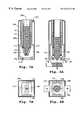
- FIGS. 5 (A) and 5 (B)are vertical and horizontal cross-sectional views, respectively, showing a magnetic pinch valve blocking the passage of reagent beads from a dispenser, in accordance with one embodiment of the present invention.
- FIGS. 6 (A) and 6 (B)are vertical and horizontal cross-sectional views, respectively, showing an electromagnet inducing the magnetic pinch valve of FIGS. 5 (A) and 5 (B) to permit the passage of reagent beads.
- FIGS. 7 (A) and 7 (B)are vertical and horizontal cross-sectional views, respectively, showing a magnetic pinch valve blocking the passage of a fluidic reagent from a dispenser, in accordance with a further embodiment of the present invention.
- FIGS. 8 (A) and 8 (B)are vertical and horizontal cross-sectional views, respectively, showing an electromagnet inducing the magnetic pinch valve of FIGS. 7 (A) and 7 (B) to permit the passage of an aliquot of fluidic reagent.
- FIG. 9 (A)is a side cross-sectional view showing a spring-biased lever blocking the passage of reagent-carrying ampules from a dispenser, in accordance with one embodiment of the present invention.
- FIG. 9 (B)is a side cross-sectional view showing a rod-like actuator deflecting the spring-biased lever of FIG. 9 (A), so that a single reagent-carrying ampule can fall from the dispenser into an underlying guide or funnel member.
- FIG. 10is a perspective view of the reagent storage and dispensing system of the present invention in the context of a larger system for loading microcard wells with reagent-carrying beads.
- the systemgenerally includes a movable table or platform assembly, denoted as 12 , disposed under an addressable array of reagent dispensers, as at 16 , equipped to serially dispense a plurality of reagents.
- addressable arrayrefers to an array having a known reagent associated with a known location (address) in the array.
- Platform assembly 12includes an upper support 22 mounted on a lower support 26 .
- Lower support 26is movable such that a fixed (i.e., constant) target or reference region thereof, e.g., as indicated at 26 a in the exploded view of FIG. 3, can be positioned below any selected dispenser of array 16 .
- Upper support 22is movable such that any selected (i.e., variable) target site of a receptacle-holding area thereof, visible as stippled region 22 a in the embodiment of FIG. 3, can be positioned over the fixed target region of lower support 26 .
- the fixed target region of the lower supportis positioned under a dispenser holding a desired reagent.
- a selected target site of the upper support's receptacle-holding areais positioned over the lower support's fixed target region.
- a particular receptacle held in a specific place on the receptacle-holding areasuch as a well of multiwell plate 36 , will be situated over the selected target site.
- Dispensed reagentthen, will fall toward the selected target site, landing in the receptacle. This procedure can be repeated to load other selected receptacles with desired reagents.
- the upper and lower supportswhich can be xy positioners, e.g., stages, tables or similar devices, are adapted for variable positioning along respective, generally horizontal planes. Such positioning can be effected using automated means, e.g., motorized assemblies, or it can be manually effected.
- each of two xy stagesis disposed in mechanical communication with a respective computer-controlled stepper motor (not shown) via a respective screw arrangement.
- Suitable xy stages and controllersare available commercially, for example, from NSK Inc. of Japan.
- a control computerintegrates the operation of the stages, for example through a program written in an event driven language such as LABVIEW® or LABWINDOWS® (National Instruments Corp., Austin, Tex.).
- the LABVIEW softwareprovides a high level graphical programming environment for controlling instruments.
- U.S. Pat. Nos. 4,901,221; 4,914,568; 5,291,587; 5,301,301; 5,301,336; and 5,481,741(each expressly incorporated herein by reference) disclose various aspects of the LABVIEW graphical programming and development system.
- the graphical programming environment disclosed in these patentsallows a user to define programs or routines by block diagrams, or “virtual instruments.” As this is done, machine language instructions are automatically constructed which characterize an execution procedure corresponding to the displayed procedure.
- Interface cards for communicating the computer with the motor controllersare also available commercially, e.g., from National Instruments Corp.
- the receptacle-holding area of the upper supportis adapted to removably support a plurality of receptacles for receiving respective reagents from the dispenser array.
- meansare provided for maintaining each receptacle in a desired location while the support is moved from one place to another.
- a slightly recessed trough-like regioncan extend below the uppermost surface of the support, into which the receptacles can be placed.
- mechanical holding meanssuch as clips, brackets, bumpers, framing, VELCRO®, or the like
- magnetic holding meanssuch as magnetic strips on the holding-area surface and a magnetically attractable undersurface on the receptacles, or the like, can be employed to maintain the containers in place.
- the receptaclesare provided as an array of spaced-apart receiving wells, such as wells 32 , formed in a tray or plate 36 .
- Each of wells 32has an opening at its upper end, permitting the well to receive and hold a reagent dispensed from above.
- a spring-loaded plate holder(not shown), attached to the upper surface of support 22 on opposing sides of holding area 22 a , prevents plate 36 from sliding across upper support 22 as it is moved.
- lower support 26is provided with a fixed (constant) reference or target region, such as area 26 a visible in FIG. 3 .
- the fixed target regionis a specific portion of the lower support (i) that is positionable under any dispenser of the dispenser array, and (ii) over which any selected (variable) site of the receptacle-holding area can be positioned.
- placement of the fixed target regionwill be determined by the presence of one or more elements, discussed below, each having a position and/or operational range of motion that is substantially fixed above a particular area of the lower support's upper surface.
- the fixed target regioncan lie under a radiation beam, such as beam 38 in FIGS.
- the fixed target regioncan be located below a guide or funnel member, as at 40 in FIGS. 2-3, for channeling reagent dispensed from an overhead dispenser to a selected site on the receptacle holding area.
- the fixed target regioncan be positioned in the vicinity of a release mechanism or actuator, as at 44 in FIGS. 2-3, for causing a selected reagent dispenser to dispense a desired reagent. Where more than one of the above components are employed, they will typically all be located in the general area at or above the fixed target region. Details of such components are discussed more fully below.
- each reagent dispensertakes the form of an elongated container, such as cylindrical or tubular container 42 shown poised above array 16 in FIG. 1 .
- the containerscan be formed, for example, of plastic, glass, and/or metal, or other material.
- each containeris a rigid cylinder formed of a metal or metal alloy (e.g., aluminum, an aluminum alloy, or stainless steel), intended for repeated uses.
- each containeris constructed of a relatively inexpensive material, such as glass or plastic that can be readily disposed of after its contents (reagent) have been exhausted.
- each containerBy configuring each container with a sufficiently narrow diameter, a high density of such containers can be achieved.
- various embodimentscontemplate from about 2 to 8 containers per cm 2 , on average, or higher.
- One preferred embodimentcontemplates an average density of between about 3-6 containers per cm 2 ; and most preferably between about 4-5 containers per cm 2 .
- a plurality of substantially like containers, each having a diameter of less than 1 cmare disposed with substantially parallel longitudinal axes and at closely spaced positions defining an array.
- an array of such containers, each having an outer diameter of about 4 mmare arranged with a center-to-center spacing between adjacent containers of about 4.50 mm.
- Each containeris provided with a passageway configured to receive and hold a respective reagent.
- a longitudinally extending lumendenoted as 42 a , holds a plurality of reagent-containing ampules, such as 50.
- the passagewaycan be of any horizontal cross-section, such as circular, oval, polygonal, or other cross-section.
- the exposed inner sidewalls of the passagewayscan be covered with a substantially inert lining material.
- a rack or framegenerally denoted as 46 , provides a plurality of holding cells, each being configured to support one reagent container therein.
- container 42can be inserted into one of holding cells 52 of frame 46 by lowering it in the direction of the darkened arrow.
- the rackcan have any number of holding cells.
- the number of different reagents held in the rackdetermines the number of holding cells. That is, there can be a one-to-one correspondence between the number of holding cells and the number of different reagents. For situations requiring a relatively large quantity of a particular reagent, other embodiments provide such reagent in two or more is holding cells of the array.
- Rack 46can have tens, hundreds, thousands, tens of thousands, or hundreds of thousands of holding cells.
- rackis formed with 10,000 holding cells, each removably supporting a respective reagent container in a substantially upright fashion.
- any combination of up to 10,000 different reagentscan be dispensed into the wells of a multi-well tray.
- a plurality of such rackscan be utilized, for example, in an “assembly line” type arrangement.
- three 10,000 cell rackscan be arranged at respective locations along an automated system, each capable of dispensing up to 10,000 different reagents.
- each reagent stored and dispensed in accordance with the teachings of the inventionis not critical, provided only that it is compatible with the storage and dispensing means.
- the reagentwhich can be a single substance or a grouping of different substances, can be provided, for example, as a solid, liquid, powder, emulsion, suspension or substantially any combination thereof.
- a coating materialis applied to a reagent core to form particulates, pills, beads or tablets.
- the coatingcan be dissolvable or swellable to permit access to the reagent under controllable conditions (e.g., upon exposure to a particular solvent).
- a plurality of bead-like particlesact as solid supports for the reagents.
- reagentscan be synthesized on the beads, or absorbed thereto.
- a slurry or dispersioncomprised of a reagent and binding material is used to form a plurality of beadlike particles, with each individual bead having a substantially homogenous consistency.
- a plurality of different reagentscan be formed into respective collections or groups of reagent beads, or “lots.” For example, 10,000 different reagents can be formed into 10,000 different bead lots, with each lot comprised of a plurality of substantially like beads carrying a respective reagent. Beads from each lot can then be loaded into respective dispensers of the dispenser array.
- a plurality of bead lotsare formed, wherein each bead includes a reagent core covered with a coating material, such as a gelatin, having well-defined physical and chemical properties.
- a coating materialsuch as a gelatin, having well-defined physical and chemical properties.
- all beads in all lotsbear substantially the same outer coating (i.e., a “generic” coating).
- the coating materialis chosen so that any residues are innocuous to the system.
- the beadscan be formed with a diameter slightly less than that of one of the passageways of the dispenser array, so that the beads can be stacked in each container, one on top of the other, for gravity-fed dispensing.
- beads having a diameter of between about 3.50-3.90 mm, and preferably about 3.70 mmcan be stacked in a container having a passageway with a diameter of about 4 mm.
- the beadscan be relatively small, e.g., each having a diameter of less than about 1 mm. In one preferred embodiment, each bead has a diameter of between about 275-325 cm, and preferably about 300 ⁇ m.
- a plurality of such beadscan be placed in a capsule or ampule to be dispensed as a unit. For example, hundreds or thousands of beads from the same or substantially identical lots can be packed into plastic ampules.
- FIG. 4shows reagent-carrying beads 62 disposed in bulletshaped ampules 50 .
- the various passageways in the dispenser arraycan be loaded with a plurality of such ampules, each containing beads from respective lots. As best seen in FIG. 4, the ampules can be dimensioned to move downward through the passageways under the force of gravity in a substantially single-file fashion.
- the ampulescan be provided with a cover member over an upper opening thereof.
- the cover membercan be, for example, a removable cap or dome having an open end configured to fit snugly about the upper region of an ampule.
- a frangible sheet-like film or membranesuch as membranes 66 in FIG. 4, can be applied to an upper rim or lip surrounding the upper opening of each ampule. Access to the beads can be gained, for example, by removing or rupturing the membrane cover.
- the cover over each ampuleforms a substantially airtight seal, protecting the reagent contents of the ampule from the ambient atmosphere.
- the sealcan be effected, for example, using conventional adhesives or by heating-sealing techniques.
- the sealed ampulescan further contain an inert gas, such as nitrogen or the like.
- the reagent in each dispenserincludes components useful for real time fluorescence-based measurements of nucleic acid amplification products (such as PCR) as described, for example, in PCT Publication WO 95/30139 and U.S. patent application Ser. No. 08/235,411, each of which is expressly incorporated herein by reference.
- each containerholds an analyte-specific reagent effective to react with a selected analyte that may be present in a sample.
- the analyte-specific reagentcan include first and second oligonucleotide primers having sequences effective to hybridize to opposite end regions of complementary strands of a selected polynucleotide analyte segment, for amplifying the segment by primer-initiated polymerase chain reaction.
- the analyte-specific detection reagentcan further include a fluorescer-quencher oligonucleotide capable of hybridizing to the analyte segment in a region downstream of one of the primers, for producing a detectable fluorescent signal when the analyte is present in the sample.
- each containercan be formed with window regions through which the tracking numbers on the ampules can be observed.
- the window regionscan be of a transparent material, such as glass or plastic, or they can be openings or notches formed in the sidewalls of the containers.
- each tracking numberis provided in a machine-readable format, such as a bar code.
- a machine-readable formatsuch as a bar code.
- An operatorcan manually scan the bar codes, or they can be scanned in an automated fashion using robots.
- a robotpicks up a container from a tray of reagent tubes and wands a bar code to learn and/or confirm the identity of the reagent held therein.
- a control computerinstructs the robot to place the tube in a designated holding cell of a rack.
- Controllable dispensing of each reagentis provided by a gate mechanism located at a lower outlet region of each dispenser.
- Each gate mechanismis independently operable between (i) an opened condition permitting passage of a respective reagent through the outlet region, and (ii) a closed condition whereat such passage is blocked.
- the particular construction of the gate mechanismis not critical, provided only that it is capable of retaining the reagent held in the respective container until such time that it is desired to dispense the reagent.
- each gate mechanismis preferably operable on an individual basis, so that the various reagents can be dispensed one at a time.
- each gate mechanismincludes a magnetic pinch valve having first and second magnets that are pivotally mounted in facing relation at a respective container outlet region.
- the pinch valve magnetshave lower, confronting north and south pole regions that are urged toward one another by magnetic forces, thereby normally disposing the gate mechanism in a “closed” condition. Additional structure may be included to supplement or enhance such normal positioning of the pivotal magnets.
- FIGS. 5 and 6show one particular embodiment of a magnetic pinch valve that is especially useful for dispensing reagent-carrying beads.
- a supportive insert or plugsuch as 170
- Frictional engagement of the insert's outer sidewall with the inner sidewall of a respective holding cellcan hold the insert in place.
- Adhesives or other retaining meansmay be employed to ensure the long-term placement of each insert.
- the lower end of an elongated container 142containing reagent beads 188 , rests on an upper, inwardly flanged portion of insert 170 b .
- Insert 170provides pivot points, denoted as 174 and 176 , on opposing inner sidewall portions to which respective permanent magnets 178 , 180 pivotally attach at their midregions, e.g., by way of pivot pins.
- each pivotal magnet 178 , 180is substantially C-shaped in horizontal cross-section. Pivotal magnets 178 , 180 are oriented such that their upper and lower end regions are of opposite polarity.
- a third permanent magnet, denoted as 184is fixedly positioned along a sidewall portion of insert 170 , above pivot points 174 , 176 .
- this stationary magnet 184is disposed adjacent an upper region of one of the pivotal magnets, 178 or 180 ; and the other end of magnet 184 is disposed adjacent an upper region of the other pivotal magnet.
- Stationary magnet 184is oriented such that the polarity of each such end is opposite that of the upper region of the pivotal magnet adjacent thereto. Accordingly, in the normal state, the upper region of each pivotal magnet 178 , 180 is attracted to an adjacent portion of the sidewall-mounted magnet 184 and, at the same time, the confronting north and south pole regions of the pivotal magnets are attracted toward one another.
- magnets 178 , 180pivot about their respective pivot points 174 , 176 so that their lower north and south pole regions swing toward one another; thereby assuming the closed condition, as shown in FIGS. 5 (A) and 5 (B).
- the outlet regionis constricted such that the reagent beads 188 are not able to fall out.
- Electromagnet 192is used as the release mechanism. Electromagnet 192 has spaced-apart south and north pole portions disposed to attract the opposing north and south pole lower regions of pivotal magnets 178 , 180 , respectively, in a direction away from one another.
- electromagnet 192The magnetic force generated upon activating electromagnet 192 is sufficient to overcome the previously-described normal closing force, thereby swinging the lower regions of pivotal magnets 178 , 180 apart so that one of the beads 188 can fall through a central opening 170 a at the bottom of insert 170 . As best seen in FIG. 6 (A), upon swinging the lower regions of pivotal magnets 178 , 180 apart, the upper regions swing toward one another, thereby blocking the passage of any additional beads 188 . Once a bead has been dispensed, electromagnet 192 can be deactivated, permitting the gate mechanism to return to the closed position, as shown in FIGS. 5 (A)- 5 (B). Electromagnet 192 can then be moved to another container for dispensing another reagent. It should be appreciated that this arrangement allows for the realization of controllable, singlebead dispensing.
- FIGS. 7 and 8show an embodiment of a pinch valve especially useful for dispensing a fluidic reagent.
- two substantially planar, permanent magnets 278 , 280attach at their uppermost ends to a support member 270 , for swinging motion about respective pivotal connections 274 , 276 .
- the pivotal connections 274 , 276are disposed on opposing sides of a lowermost opening of elongated container 242 .
- Support member 270is fixed to a lower end region of container 242 .
- annular cavity 287extends upwardly from a lowermost rim or lip of container 242 , circumscribing longitudinal passageway 242 a .
- An upstanding cylindrical collar 270 aformed at the top of support member 270 , is configured to fit snugly into cavity 287 . Collar 270 a can be maintained in cavity 287 by frictional forces and/or adhesive agents.
- a plate 272is secured against a lowermost end of holding cell 252 to provide a lower foundation for supporting the container and gate assembly therein.
- Gasket members 279 , 281are affixed to opposite inner sidewall portions of support member 270 .
- Gasket members 279 , 281provide opposing planar surfaces positioned for sliding, substantially fluid tight, contact with the lateral side-edges of pivotal magnets 278 , 280 .
- the opposing planar surfaces of gasket members 279 , 281can be formed of a hydrophobic material, and/or treated to exhibit hydrophobic characteristics, to discourage undesired leakage of the liquid reagent 288 .
- pivotal magnets 278 , 280are oriented such that they having lower end regions of opposite polarity. So arranged, the lower ends of pivotal magnets 278 , 280 are normally attracted such that they swing toward one another and make contact, establishing a substantially fluid-tight seal (i.e., a “closed” position). In this regard, one or both magnets 278 , 280 can bear a polymeric coating (not shown) along the region of contact to assist in the formation of the fluid-tight seal.
- Electromagnet 292has spaced-apart south and north pole portions disposed to attract the opposing north and south pole lower regions of pivotal magnets 278 , 280 , respectively, in a direction away from one another, The magnetic force generated upon activating electromagnet 292 is sufficient to overcome the previously-described normal closing force, thereby swinging the lower regions of pivotal magnets 278 , 280 apart so that an aliquot of fluidic reagent 288 can fall through a central opening 272 a in plate 272 .
- electromagnet 292The duration of activation of electromagnet 292 can be used to gauge the amount of liquid reagent dispensed.
- electromagnet 292When electromagnet 292 is turned off, the normal attraction between the opposing lower end regions of magnets 278 , 280 returns the valve to a closed position.
- each gate mechanismis a resiliently deflectable lever having a protrusion that normally extends into a respective outlet region.
- an elongated leverindicated generally by the reference numeral 302 , extends longitudinally along the outer sidewall of container 342 , proximate the container's lower outlet region.
- Upper and lower nubs or protrusionsdenoted respectively as 302 b and 302 c , project outwardly from one side of lever 302 , towards container 342 .
- Container 342in turn, is provided with upper and lower bores, indicated respectively as 342 b and 342 c , that extend fully through its sidewall at locations adjacent to lever 302 . More particularly, each of bores 342 b , 342 c is positioned in alignment with a respective one of protrusions 302 b , 302 c , and is configured to removably receive such protrusion therein.
- a resilient spring membersuch as leaf spring 351
- leaf spring 351is secured at one of its ends to a support structure 353 that is fixedly positioned near the lower outlet region of container 342 .
- the other end of leaf spring 351is disposed to act against a side of lever 302 , opposite container 342 .
- Leaf spring 351provides a normal biasing force, along the direction “F,” that presses the lower end region of lever 302 against container 342 .
- lower protrusion 302 cextends through lower bore 342 c and into passageway 342 a at the container's lower outlet region, as shown in FIG. 9 (A).
- lower protrusion 302 cblocks the egression of any reagent-carrying ampules 388 a - 388 c .
- Upper protrusion 302 bis positioned outside of passageway 342 a in the normal, closed position.
- a release mechanismis moved to a position under the outlet region of a selected container.
- the release mechanismis operable to overcome the closing force that normally prevents the egression of ampules.
- an elongated rod 372can be employed as the release mechanism.
- Rod 372is adapted for reciprocal linear motion between (i) a retracted position, whereat rod 372 is positionable below a selected lever, such as lever 302 in FIG. 9 (A), to (ii) an extended position, whereat a rounded-head portion of rod, denoted at 372 a , can abut and press against a lower, outwardly-angled cam surface of lever, as at 302 a in FIG. 9 (B), thereby deflecting lever 302 away from container 342 .
- Such motion of rod 372can be effected, for example, by providing rod at the end region of a movable plunger extending from a conventional solenoid assembly.
- lever 302when lever 302 is deflected in the manner just described, lower protrusion 302 c is withdrawn from passageway 342 a , permitting the bottommost reagent-carrying ampule 388 a to fall from the container's lower outlet region. Also during such deflection, upper protrusion 302 b is received within upper bore 342 b such that it extends into passageway 342 a , preventing the egression of any remaining ampules 388 b - 388 c . Upon returning rod 372 to its retracted position, lever 302 reassumes its normally closed position, as in FIG. 9 (A), preventing the passage of any ampules. It should be appreciated that this arrangement permits controllable, single-ampule dispensing.
- the release mechanismoperates according to magnetic principles.
- the lower end of the resiliently deflectable lever and the upper head portion of reciprocally movable rodare magnetically polarized, or polarizable, to exhibit the same polarity (e.g., both being “N”).
- the levercan be deflected by moving the rod into proximity with the lever's lower end, so that the like magnetic pole portions repel one another.
- contact between the rod and the leveris not required in this embodiment.
- the magnetic repulsionis sufficient to deflect the lever away from the container, thereby permitting a reagent-carrying ampule to fall from the container's lower outlet region.
- any of the above-described release mechanismscan be adapted for variable positioning along a generally horizontal plane under the dispenser array by mounting it to the upper surface of the lower xy stage.
- a mounting assemblysuch as bracket 51 of FIGS. 1-3, can be used to hold the release mechanism.
- one end of bracket 51is affixed to the upper surface of lower xy stage 26 .
- the other (free) end of bracket 51extends into the region between the platform assembly 12 and the dispenser array 16 , whereat the release mechanism is supported, as schematically indicated at 44 .
- a detection assemblycan be provided for detecting the passage of reagent into a receptacle from a selected overhead dispenser.
- the region between a radiation source or emitter, such as laser 37 , and a radiation sensor, as at 39defines a detection zone.
- both laser 37 and sensor 39are fixedly positioned at respective locations on the upper surface of the lower xy stage 26 , on opposing sides of upper xy stage 22 .
- This constructionpermits movement of the detection zone along a generally horizontal plane under dispenser array 16 with movement of the lower xy stage 26 .
- a narrow-width beamindicated at 38 , can be directed from laser 37 along the detection zone and detected by sensor 39 .
- An interruption in the beam 38indicates the passage of a reagent from a dispenser above the detection zone.
- Lasers and sensorssuitable for use in practicing the invention, are available commercially, for example, from Edmund Scientific (Barrington, N.J.).
- beam 38can also be employed to confirm the identity of a dispensed reagent.
- beam 38can “double” as a bar-code scanner.
- each reagent-carrying ampulebears a bar code that is unique to the particular type of reagent held therein.
- the bar codeis read and the information is passed on to the control computer. The computer can then positively identify the dispensed reagent, and take appropriate corrective measures in the event of a dispensing error.
- a guide or funnel membercan be provided in the region between the dispenser array and the platform assembly for channeling reagent dispensed from an overhead dispenser to a selected site on the receptacle-holding area of the upper xy stage.
- a guide memberindicated schematically at 40
- This constructionpermits movement of the guide member 40 along a generally horizontal plane under the dispenser array 16 with movement of the lower xy stage 26 .
- guide member 40will be positioned under a selected dispenser of array 16 .
- a selected receptaclesuch as a particular well of multi-well plate 36 , will be positioned under the guide member by appropriately moving the upper xy stage 22 . Such positioning of the guide member and the receptacle will preferably occur simultaneously.
- a dispensed reagentthen, will fall through a central, vertically extending channel of guide member 40 on its way from the selected dispenser to the selected receptacle.
- a guide memberin one particular embodiment, shown in FIGS. 9 (A) and 9 (B), includes (i) an upper opening 340 a , (ii) a lower opening 340 c , smaller than the upper opening 340 a , and (iii) a conical or funnel-shaped portion 340 b , between the upper and lower openings. Also in this embodiment, it should be noted that the guide member 340 and reciprocally-movable rod 372 are conveniently provided together in a common housing.
- the fixed target regionis primarily a reference point that, when positioned under a selected dispenser, facilitates the proper and simultaneous positioning of one or more additional components thereunder.
- each of the following elementsis positioned at an appropriate location with respect to a selected container, as described, upon moving the fixed target region 26 a to a location under such container:
- radiation beam 38is located under the selected container so that any reagent dispensed from the container will break the beam;
- guide or funnel member 40is disposed with its upper, large opening axially aligned with the lower outlet region of the selected container so that dispensed reagent will fall therein;
- release mechanism 44is positioned proximate a normally closed gate mechanism at the lower outlet region of the selected container.
- a selected well of multi-well plate 36supported at the receptacle-holding area of the upper xy stage 22 , can be moved to a position over the fixed target region while the fixed target region is being moved under the selected receptacle as just described. In this way, the receptacle, too, can be quickly and accurately positioned to receive a dispensed reagent.
- operation of the various components and sub-assemblies described abovecan be controlled and orchestrated using the LABVIEW® or LABWINDOWS® software from National Instruments (Austin, Tex.) by techniques known in the art.
- an array of holding cells 52 in rack 46are loaded with respective containers 42 , each holding a particular reagent.
- a data set or tableis created comprised of values identifying each location or address of the holding-cell matrix with its particular resident reagent.
- the data setis stored electronically on a drive unit accessible to a control computer.
- the reagentsare maintained in rack 46 until dispensed, e.g., as follows.
- Multi-well plate 36is placed on receptacle-holding area 22 a of upper xy stage 22 .
- a plurality of reagents, stored in rack 46are selected for dispensing into chosen wells 32 of plate 36 , and this information is fed to the control computer.
- the computeraccesses the data set of location information to determine which containers hold the selected reagents, and a loading sequence is constructed and held in memory.
- the computersignals the motor controller to move lower xy stage 26 to a location whereat its fixed target region 26 a is disposed under the first container of the loading sequence.
- upper xy stage 22positions a selected target region of the receptacle-holding area 22 a , underlying a chosen well of multi-plate 36 , over the fixed target region 26 a .
- these stepsserve to position radiation beam 38 , guide member 40 , and release mechanism 44 at appropriate respective locations proximate a lower outlet region of the container, as well as to position the chosen well of plate 36 under the container.
- the computerthen signals activation of release mechanism 44 , causing the gate mechanism at the lower outlet region of the container to open and dispense an aliquot of its respective reagent into the chosen well of plate 36 .
- a correctly dispensed substancewill briefly prevent radiation beam 38 from reaching sensor 39 , indicating successful dispensing.
- the dispensing system of the present inventionis utilized as a sub-assembly in a larger system for loading an array of very small wells in a microcard with respective reagents.
- a 384 -well platedenoted as 436 , serves as a source of reagent for serially loading target 384 -well microcards, such as 441 , supported for movement on a carousel assembly 449 .
- the wells of both the plate and the microcardsare disposed in 16 ⁇ 24 arrays, spaced about 4.5 mm center-to-center.
- the wells of the platehowever, have a greater diameter than the wells of the microcards.
- each well of the platecan be configured with a diameter of about 3 mm, while each well of the microcards can be formed with a diameter of about 1 mm.
- each well of the multi-well plate 436is loaded with a respective reagent-carrying ampule, in accordance with the foregoing detailed description.
- a robotsuch as 443 , then moves the ampule-loaded plate, in the direction of darkened arrow “P,” to a pick-and-place unit 445 .
- Pick-and-place unit 445simultaneously retrieves a reagent bead from each ampule in the plate, and retains the beads at spaced-apart locations defining an array corresponding to the plate and microcard arrays.
- Pick-and-place unit 445then rotates about its central axis to position the retained beads over the wells of a microcard supported on the carousel at a location directly adjacent thereto, at which point it releases the beads.
- a bead distributor, such as 447interposed between pickand-place unit 445 and the target microcard, separately channels each released bead into its designated well.
- the loaded microcard wellscan then be used to carry out a desired assay or reaction, such as real-time PCR.
- micro-card loading systemAdditional details of the micro-card loading system are provided in co-pending application Atty. Docket No. 0550-0076/4424, filed concurrently herewith and expressly incorporated herein by reference.
Landscapes
- Chemical & Material Sciences (AREA)
- General Health & Medical Sciences (AREA)
- Immunology (AREA)
- General Physics & Mathematics (AREA)
- Pathology (AREA)
- Physics & Mathematics (AREA)
- Health & Medical Sciences (AREA)
- Life Sciences & Earth Sciences (AREA)
- Analytical Chemistry (AREA)
- Biochemistry (AREA)
- Organic Chemistry (AREA)
- Chemical Kinetics & Catalysis (AREA)
- Robotics (AREA)
- Engineering & Computer Science (AREA)
- Automatic Analysis And Handling Materials Therefor (AREA)
- Separation By Low-Temperature Treatments (AREA)
- Pharmaceuticals Containing Other Organic And Inorganic Compounds (AREA)
- Medical Preparation Storing Or Oral Administration Devices (AREA)
- Investigating Or Analysing Biological Materials (AREA)
- Feeding, Discharge, Calcimining, Fusing, And Gas-Generation Devices (AREA)
- Apparatus Associated With Microorganisms And Enzymes (AREA)
- Investigating Or Analysing Materials By The Use Of Chemical Reactions (AREA)
Abstract
Description
Claims (30)
Priority Applications (13)
| Application Number | Priority Date | Filing Date | Title |
|---|---|---|---|
| US09/251,232US6432719B1 (en) | 1999-02-16 | 1999-02-16 | Matrix storage and dispensing system |
| EP02013541AEP1254703A3 (en) | 1999-02-16 | 2000-02-15 | Matrix storage and dispensing system |
| AU29952/00AAU746802B2 (en) | 1999-02-16 | 2000-02-15 | Matrix storage and dispensing system |
| DE60000874TDE60000874T2 (en) | 1999-02-16 | 2000-02-15 | MATRIX SYSTEM FOR STORAGE AND DELIVERY |
| CA002361275ACA2361275C (en) | 1999-02-16 | 2000-02-15 | Matrix storage and dispensing system |
| PCT/US2000/003841WO2000048735A2 (en) | 1999-02-16 | 2000-02-15 | Matrix storage and dispensing system |
| AT00908647TATE228393T1 (en) | 1999-02-16 | 2000-02-15 | MATRIX SYSTEM FOR STORAGE AND DISPENSING |
| JP2000599509AJP3844967B2 (en) | 1999-02-16 | 2000-02-15 | Matrix storage and distribution system |
| EP00908647AEP1171230B1 (en) | 1999-02-16 | 2000-02-15 | Matrix storage and dispensing system |
| US09/955,554US7101510B2 (en) | 1999-02-16 | 2001-09-18 | Matrix storage and dispensing system |
| US10/488,437US20050013734A1 (en) | 1999-02-16 | 2002-09-09 | Matrix storage and retrieval system |
| JP2005295743AJP2006047320A (en) | 1999-02-16 | 2005-10-07 | Matrix storage and distribution system |
| US11/436,296US7361309B2 (en) | 1999-02-16 | 2006-05-18 | Matrix storage and dispensing system |
Applications Claiming Priority (1)
| Application Number | Priority Date | Filing Date | Title |
|---|---|---|---|
| US09/251,232US6432719B1 (en) | 1999-02-16 | 1999-02-16 | Matrix storage and dispensing system |
Related Child Applications (1)
| Application Number | Title | Priority Date | Filing Date |
|---|---|---|---|
| US09/955,554ContinuationUS7101510B2 (en) | 1999-02-16 | 2001-09-18 | Matrix storage and dispensing system |
Publications (1)
| Publication Number | Publication Date |
|---|---|
| US6432719B1true US6432719B1 (en) | 2002-08-13 |
Family
ID=22951044
Family Applications (1)
| Application Number | Title | Priority Date | Filing Date |
|---|---|---|---|
| US09/251,232Expired - LifetimeUS6432719B1 (en) | 1999-02-16 | 1999-02-16 | Matrix storage and dispensing system |
Country Status (8)
| Country | Link |
|---|---|
| US (1) | US6432719B1 (en) |
| EP (2) | EP1171230B1 (en) |
| JP (2) | JP3844967B2 (en) |
| AT (1) | ATE228393T1 (en) |
| AU (1) | AU746802B2 (en) |
| CA (1) | CA2361275C (en) |
| DE (1) | DE60000874T2 (en) |
| WO (1) | WO2000048735A2 (en) |
Cited By (33)
| Publication number | Priority date | Publication date | Assignee | Title |
|---|---|---|---|---|
| US20020015666A1 (en)* | 1999-02-16 | 2002-02-07 | Pe Corporation (Ny) | Matrix storage and dispensing system |
| US20030021734A1 (en)* | 1999-02-16 | 2003-01-30 | Vann Charles S. | Bead dispensing system |
| US20030113233A1 (en)* | 2001-10-26 | 2003-06-19 | Elizabeth Nanthakumar | Resin dispensing device |
| US20040146434A1 (en)* | 2002-11-04 | 2004-07-29 | Transform Pharmaceuticals, Inc. | Methods of manipulating small amounts of solids |
| US6815198B2 (en)* | 2000-04-27 | 2004-11-09 | Hitachi Electronics Engineering Co., Ltd. | Apparatus for automated preparation of DNA samples and reactor for preparing DNA samples |
| US20040224339A1 (en)* | 2003-03-31 | 2004-11-11 | Canon Kabushiki Kaisha | Biochemical reaction cartridge |
| US20040258573A1 (en)* | 2003-06-18 | 2004-12-23 | Rainer Treptow | System for proportioning sample liquid |
| US20050035143A1 (en)* | 2003-08-15 | 2005-02-17 | Peter Massaro | Method and apparatus for handling small volume fluid samples |
| US20050100943A1 (en)* | 2000-04-11 | 2005-05-12 | Hideki Kambara | Method of producing probe arrays for biological materials using fine particles |
| US20050186578A1 (en)* | 2004-02-20 | 2005-08-25 | Sven Bulow | Chamber array arrangement |
| US20050226771A1 (en)* | 2003-09-19 | 2005-10-13 | Lehto Dennis A | High speed microplate transfer |
| US20050233472A1 (en)* | 2003-09-19 | 2005-10-20 | Kao H P | Spotting high density plate using a banded format |
| US20060063159A1 (en)* | 2004-09-22 | 2006-03-23 | Applera Corporation | Post-synthesis processing system for supported oligonucleotides, and method |
| US20060088448A1 (en)* | 2004-07-27 | 2006-04-27 | Protedyne Corporation | Method and apparatus for applying a pressure differential to a multi-well plate |
| US20060108197A1 (en)* | 2003-01-06 | 2006-05-25 | Toshio Okuyama | Device for discharge rod-like product whose one end is larger sized |
| US20070207450A1 (en)* | 2003-06-05 | 2007-09-06 | Bioprocessors Corp. | System and method for process automation |
| US20070258862A1 (en)* | 2006-05-02 | 2007-11-08 | Applera Corporation | Variable volume dispenser and method |
| US20080000892A1 (en)* | 2006-06-26 | 2008-01-03 | Applera Corporation | Heated cover methods and technology |
| US20080006202A1 (en)* | 2006-06-26 | 2008-01-10 | Applera Corporation | Compressible transparent sealing for open microplates |
| US7396512B2 (en) | 2003-11-04 | 2008-07-08 | Drummond Scientific Company | Automatic precision non-contact open-loop fluid dispensing |
| US20080182340A1 (en)* | 2007-01-26 | 2008-07-31 | Lemmo Anthony V | Non-contact positive dispense solid powder sampling apparatus and method |
| US20080269076A1 (en)* | 2005-05-06 | 2008-10-30 | Applera Corporation | Multiple Capillary Device and Method for Synthesis and Dispensing |
| US20090086198A1 (en)* | 2007-10-01 | 2009-04-02 | Walter Gotschy | Micro Cuvette Assembly and Use Thereof |
| US20100011889A1 (en)* | 2008-07-16 | 2010-01-21 | Biodot, Inc. | Handheld powder handling devices and related methods |
| US8040619B2 (en) | 2003-09-19 | 2011-10-18 | Applied Biosystems, Llc | Optical camera alignment |
| WO2012006706A3 (en)* | 2010-07-14 | 2012-06-28 | Tecnotok Indústria De Máquinas Ltda | Metering device |
| US9857367B2 (en) | 2009-07-29 | 2018-01-02 | Dynex Technologies, Inc. | Sample plate systems and methods |
| US10307724B2 (en) | 2015-07-02 | 2019-06-04 | Centrillion Technology Holdings Corporation | Systems and methods to dispense and mix reagents |
| US10376888B2 (en) | 2014-07-03 | 2019-08-13 | Centrillion Technology Holdings Corporation | Device for storage and dispensing of reagents |
| US20200315320A1 (en)* | 2019-04-05 | 2020-10-08 | L'oreal R&I Rio | Bead assembly for custom formulation systems |
| US20210039087A1 (en)* | 2017-10-03 | 2021-02-11 | Qiagen Healthcare Biotechnologies Systems Limited | Device and method for storing nucleic acids |
| US20230094031A1 (en)* | 2021-09-28 | 2023-03-30 | Mikron Corporation Denver | Lyophilized bead handling |
| US12252344B2 (en)* | 2022-12-14 | 2025-03-18 | Mecalux, S.A. | Pallet stacking system on a structure, pallet rack or similar, and related methods |
Families Citing this family (14)
| Publication number | Priority date | Publication date | Assignee | Title |
|---|---|---|---|---|
| US20030054543A1 (en)* | 1997-06-16 | 2003-03-20 | Lafferty William Michael | Device for moving a selected station of a holding plate to a predetermined location for interaction with a probe |
| US20020102598A1 (en)* | 1997-06-16 | 2002-08-01 | Lafferty William Michael | Positioning system for moving a selected station of a holding plate to a predetermined location for interaction with a probe |
| US6387330B1 (en)* | 2000-04-12 | 2002-05-14 | George Steven Bova | Method and apparatus for storing and dispensing reagents |
| US6613284B2 (en)* | 2001-02-01 | 2003-09-02 | V&P Scientific, Inc. | Microarrayer |
| US6943036B2 (en) | 2001-04-30 | 2005-09-13 | Agilent Technologies, Inc. | Error detection in chemical array fabrication |
| US7584240B2 (en) | 2001-11-07 | 2009-09-01 | Genvault Corporation | Automated biological sample archive for storage, retrieval and analysis of large numbers of samples for remote clients |
| US20030143329A1 (en)* | 2002-01-30 | 2003-07-31 | Shchegrova Svetlana V. | Error correction in array fabrication |
| DE10347311A1 (en)* | 2003-10-08 | 2005-05-12 | Ehrfeld Mikrotechnik Ag | Method and device for carrying out reactions |
| DE602005016402D1 (en) | 2004-05-24 | 2009-10-15 | Genvault Corp | STABLE STORAGE OF PROTEIN AND STABLE STORAGE OF NUCLEIC ACID IN RECYCLABLE FORM |
| US8283165B2 (en) | 2008-09-12 | 2012-10-09 | Genvault Corporation | Matrices and media for storage and stabilization of biomolecules |
| US9523701B2 (en) | 2009-07-29 | 2016-12-20 | Dynex Technologies, Inc. | Sample plate systems and methods |
| KR20130111899A (en)* | 2012-04-02 | 2013-10-11 | (주)제이브이엠 | Injection and related products dispensing apparatus |
| WO2014094062A1 (en)* | 2012-12-21 | 2014-06-26 | Leica Biosystems Melbourne Pty Ltd | Method of producing a reagent on-board an instrument |
| FR3057559B1 (en)* | 2016-10-13 | 2018-11-16 | Diagnostica Stago | DEVICE FOR DISPENSING BALLS, IN PARTICULAR BALLS FOR ANALYSIS CUPES |
Citations (40)
| Publication number | Priority date | Publication date | Assignee | Title |
|---|---|---|---|---|
| US3568735A (en)* | 1968-06-26 | 1971-03-09 | Cooke Eng Co | Laboratory microtitration dispensing apparatus |
| US3843053A (en) | 1973-03-29 | 1974-10-22 | Kontes Glass Co | Spotter for use in thin layer chromatography and method of forming drops therewith |
| US3974854A (en)* | 1972-09-07 | 1976-08-17 | Kurpanek W H | Valve particularly adapted for utilization in controlling the flow of blood |
| US4101284A (en) | 1977-10-25 | 1978-07-18 | Abbott Laboratories | Multiple bead dispenser for diagnostic assay |
| US4272510A (en)* | 1976-04-26 | 1981-06-09 | Smith Kendall O | Magnetic attraction transfer process for use in solid phase radioimmunoassays and in other assay methods |
| US4415098A (en) | 1981-06-15 | 1983-11-15 | Abbott Laboratories | Single bead dispenser |
| US4444336A (en) | 1980-08-27 | 1984-04-24 | Burns, Philp & Company, Ltd. | Dispensing unit |
| US4593728A (en) | 1982-11-20 | 1986-06-10 | Whitehead Thomas P | Dispensing device and recording apparatus |
| US4605408A (en)* | 1983-03-30 | 1986-08-12 | Universite Pierre Et Marie Curie Paris Vi | Artificial cardiac valve with active opening |
| US4649116A (en)* | 1983-10-27 | 1987-03-10 | Institut Pasteur | Magnetic means for withdrawing magnetic gel beads from an assay fluid |
| US4648529A (en) | 1985-06-12 | 1987-03-10 | Cetus Corporation | Dispensing apparatus for storing, draining and dispensing beads |
| US4681742A (en) | 1984-10-01 | 1987-07-21 | Cetus Corporation | Assay tray |
| US4699884A (en) | 1984-02-29 | 1987-10-13 | Gerhard Noss | Process and apparatus for the simultaneous application of a multiplicity of liquid samples to an object stage |
| US4937048A (en)* | 1983-01-31 | 1990-06-26 | Olympus Optical Company Limited | Carrier transporting apparatus and carrier container for use in an immunological analysis |
| US4952518A (en) | 1984-10-01 | 1990-08-28 | Cetus Corporation | Automated assay machine and assay tray |
| US4979955A (en)* | 1988-06-06 | 1990-12-25 | Smith Robert M | Power assisted prosthetic heart valve |
| US5011779A (en) | 1988-01-21 | 1991-04-30 | Long Island Jewish Medical Center | Apparatus for rapid deposition of test samples on an absorbent support |
| US5046539A (en) | 1989-05-26 | 1991-09-10 | The Rockefeller University | Automatic fluid dispenser for multi-welled dish |
| US5382512A (en) | 1993-08-23 | 1995-01-17 | Chiron Corporation | Assay device with captured particle reagent |
| US5445934A (en) | 1989-06-07 | 1995-08-29 | Affymax Technologies N.V. | Array of oligonucleotides on a solid substrate |
| WO1995035505A1 (en) | 1994-06-17 | 1995-12-28 | The Board Of Trustees Of The Leland Stanford Junior University | Method and apparatus for fabricating microarrays of biological samples |
| US5508200A (en) | 1992-10-19 | 1996-04-16 | Tiffany; Thomas | Method and apparatus for conducting multiple chemical assays |
| US5525302A (en)* | 1991-02-01 | 1996-06-11 | Astle; Thomas W. | Method and device for simultaneously transferring plural samples |
| US5571258A (en) | 1995-07-13 | 1996-11-05 | Pearson; Walter G. | Semi-automated medication dispenser |
| US5616299A (en) | 1995-06-06 | 1997-04-01 | Pharmacia Biotech, Inc. | Dispenser for dried biological reagent spheres |
| US5649576A (en)* | 1996-02-26 | 1997-07-22 | Pharmacopeia, Inc. | Partitioning device |
| US5677195A (en) | 1991-11-22 | 1997-10-14 | Affymax Technologies N.V. | Combinatorial strategies for polymer synthesis |
| WO1997040383A1 (en) | 1996-04-24 | 1997-10-30 | Glaxo Group Limited | Systems and methods for arraying beads |
| US5685459A (en)* | 1994-07-07 | 1997-11-11 | The Boc Group Plc | Liquid dispensing apparatus |
| WO1997044134A1 (en) | 1996-05-17 | 1997-11-27 | Incyte Pharmaceuticals, Inc. | Jet droplet device and method |
| WO1998008092A1 (en) | 1996-08-21 | 1998-02-26 | Smithkline Beecham Corporation | Rapid process for arraying and synthesizing bead-based combinatorial libraries |
| US5722470A (en) | 1995-11-09 | 1998-03-03 | Glaxo Group Limited | Bead dispensing device and methods |
| WO1998017383A1 (en) | 1996-10-21 | 1998-04-30 | Smithkline Beecham Plc | Apparatus and method for distributing beads |
| US5770860A (en) | 1996-07-12 | 1998-06-23 | Franzen; Jochen | Method for loading sample supports for mass spectrometers |
| US5773296A (en) | 1996-06-28 | 1998-06-30 | Dpc Cirrus, Inc. | Bead dispenser and bead dispenser system for immunoassay analysis |
| US5788814A (en) | 1996-04-09 | 1998-08-04 | David Sarnoff Research Center | Chucks and methods for positioning multiple objects on a substrate |
| WO1998038122A1 (en) | 1997-02-26 | 1998-09-03 | Sarnoff Corporation | Bead dispersement devices |
| US5846595A (en) | 1996-04-09 | 1998-12-08 | Sarnoff Corporation | Method of making pharmaceutical using electrostatic chuck |
| US5935859A (en)* | 1997-01-17 | 1999-08-10 | Smithkline Beecham Corporation | Apparatus and process for arraying beads |
| US5978251A (en)* | 1997-11-14 | 1999-11-02 | Ramtron International Corporation | Plate line driver circuit for a 1T/1C ferroelectric memory |
Family Cites Families (9)
| Publication number | Priority date | Publication date | Assignee | Title |
|---|---|---|---|---|
| GB2099803B (en)* | 1981-05-20 | 1984-12-05 | Goshe Dr Karabi | Tablet dispenser |
| US5306510A (en)* | 1988-01-14 | 1994-04-26 | Cyberlab, Inc. | Automated pipetting system |
| FI80152C (en)* | 1988-04-15 | 1990-04-10 | Kone Oy | Valve system e.g. for analyzer |
| DE69124556T2 (en)* | 1990-09-11 | 1997-09-11 | Prince Technologies B V | Method and device for introducing at least one volume of liquid into a tube, in particular for capillary electrophoresis systems and method and device for separating and / or analyzing a fluid material |
| KR19990008052A (en)* | 1995-04-25 | 1999-01-25 | 마이클 피 노바 | Remotely programmable matrix with storage device and uses thereof |
| US5812410A (en)* | 1995-12-14 | 1998-09-22 | Rx Excel, Inc. | System for dispensing drugs |
| FR2747900B1 (en)* | 1996-04-26 | 1998-06-26 | Fluidelec Sa | SYSTEM FOR STORING AND DISTRIBUTING OBJECTS OF VARIOUS SHAPES AND DIMENSIONS |
| EP0931259B1 (en)* | 1996-10-07 | 2006-11-29 | Discovery Partners International, Inc. | System for synthesizing a library of compounds and use thereof |
| US6045755A (en)* | 1997-03-10 | 2000-04-04 | Trega Biosciences,, Inc. | Apparatus and method for combinatorial chemistry synthesis |
- 1999
- 1999-02-16USUS09/251,232patent/US6432719B1/ennot_activeExpired - Lifetime
- 2000
- 2000-02-15DEDE60000874Tpatent/DE60000874T2/ennot_activeExpired - Lifetime
- 2000-02-15ATAT00908647Tpatent/ATE228393T1/ennot_activeIP Right Cessation
- 2000-02-15JPJP2000599509Apatent/JP3844967B2/ennot_activeExpired - Fee Related
- 2000-02-15WOPCT/US2000/003841patent/WO2000048735A2/enactiveIP Right Grant
- 2000-02-15AUAU29952/00Apatent/AU746802B2/ennot_activeCeased
- 2000-02-15EPEP00908647Apatent/EP1171230B1/ennot_activeExpired - Lifetime
- 2000-02-15CACA002361275Apatent/CA2361275C/ennot_activeExpired - Fee Related
- 2000-02-15EPEP02013541Apatent/EP1254703A3/ennot_activeWithdrawn
- 2005
- 2005-10-07JPJP2005295743Apatent/JP2006047320A/enactivePending
Patent Citations (41)
| Publication number | Priority date | Publication date | Assignee | Title |
|---|---|---|---|---|
| US3568735A (en)* | 1968-06-26 | 1971-03-09 | Cooke Eng Co | Laboratory microtitration dispensing apparatus |
| US3974854A (en)* | 1972-09-07 | 1976-08-17 | Kurpanek W H | Valve particularly adapted for utilization in controlling the flow of blood |
| US3843053A (en) | 1973-03-29 | 1974-10-22 | Kontes Glass Co | Spotter for use in thin layer chromatography and method of forming drops therewith |
| US4272510A (en)* | 1976-04-26 | 1981-06-09 | Smith Kendall O | Magnetic attraction transfer process for use in solid phase radioimmunoassays and in other assay methods |
| US4101284A (en) | 1977-10-25 | 1978-07-18 | Abbott Laboratories | Multiple bead dispenser for diagnostic assay |
| US4444336A (en) | 1980-08-27 | 1984-04-24 | Burns, Philp & Company, Ltd. | Dispensing unit |
| US4415098A (en) | 1981-06-15 | 1983-11-15 | Abbott Laboratories | Single bead dispenser |
| US4593728A (en) | 1982-11-20 | 1986-06-10 | Whitehead Thomas P | Dispensing device and recording apparatus |
| US4937048A (en)* | 1983-01-31 | 1990-06-26 | Olympus Optical Company Limited | Carrier transporting apparatus and carrier container for use in an immunological analysis |
| US4605408A (en)* | 1983-03-30 | 1986-08-12 | Universite Pierre Et Marie Curie Paris Vi | Artificial cardiac valve with active opening |
| US4649116A (en)* | 1983-10-27 | 1987-03-10 | Institut Pasteur | Magnetic means for withdrawing magnetic gel beads from an assay fluid |
| US4699884A (en) | 1984-02-29 | 1987-10-13 | Gerhard Noss | Process and apparatus for the simultaneous application of a multiplicity of liquid samples to an object stage |
| US4952518A (en) | 1984-10-01 | 1990-08-28 | Cetus Corporation | Automated assay machine and assay tray |
| US4681742A (en) | 1984-10-01 | 1987-07-21 | Cetus Corporation | Assay tray |
| US4648529A (en) | 1985-06-12 | 1987-03-10 | Cetus Corporation | Dispensing apparatus for storing, draining and dispensing beads |
| US5011779A (en) | 1988-01-21 | 1991-04-30 | Long Island Jewish Medical Center | Apparatus for rapid deposition of test samples on an absorbent support |
| US4979955A (en)* | 1988-06-06 | 1990-12-25 | Smith Robert M | Power assisted prosthetic heart valve |
| US5046539A (en) | 1989-05-26 | 1991-09-10 | The Rockefeller University | Automatic fluid dispenser for multi-welled dish |
| US5445934A (en) | 1989-06-07 | 1995-08-29 | Affymax Technologies N.V. | Array of oligonucleotides on a solid substrate |
| US5525302A (en)* | 1991-02-01 | 1996-06-11 | Astle; Thomas W. | Method and device for simultaneously transferring plural samples |
| US5677195A (en) | 1991-11-22 | 1997-10-14 | Affymax Technologies N.V. | Combinatorial strategies for polymer synthesis |
| US5508200A (en) | 1992-10-19 | 1996-04-16 | Tiffany; Thomas | Method and apparatus for conducting multiple chemical assays |
| US5382512A (en) | 1993-08-23 | 1995-01-17 | Chiron Corporation | Assay device with captured particle reagent |
| WO1995035505A1 (en) | 1994-06-17 | 1995-12-28 | The Board Of Trustees Of The Leland Stanford Junior University | Method and apparatus for fabricating microarrays of biological samples |
| US5685459A (en)* | 1994-07-07 | 1997-11-11 | The Boc Group Plc | Liquid dispensing apparatus |
| US5616299A (en) | 1995-06-06 | 1997-04-01 | Pharmacia Biotech, Inc. | Dispenser for dried biological reagent spheres |
| US5571258A (en) | 1995-07-13 | 1996-11-05 | Pearson; Walter G. | Semi-automated medication dispenser |
| US5722470A (en) | 1995-11-09 | 1998-03-03 | Glaxo Group Limited | Bead dispensing device and methods |
| US5649576A (en)* | 1996-02-26 | 1997-07-22 | Pharmacopeia, Inc. | Partitioning device |
| US5788814A (en) | 1996-04-09 | 1998-08-04 | David Sarnoff Research Center | Chucks and methods for positioning multiple objects on a substrate |
| US5846595A (en) | 1996-04-09 | 1998-12-08 | Sarnoff Corporation | Method of making pharmaceutical using electrostatic chuck |
| WO1997040383A1 (en) | 1996-04-24 | 1997-10-30 | Glaxo Group Limited | Systems and methods for arraying beads |
| US6074609A (en)* | 1996-04-24 | 2000-06-13 | Glaxo Wellcome Inc. | Systems for arraying beads |
| WO1997044134A1 (en) | 1996-05-17 | 1997-11-27 | Incyte Pharmaceuticals, Inc. | Jet droplet device and method |
| US5773296A (en) | 1996-06-28 | 1998-06-30 | Dpc Cirrus, Inc. | Bead dispenser and bead dispenser system for immunoassay analysis |
| US5770860A (en) | 1996-07-12 | 1998-06-23 | Franzen; Jochen | Method for loading sample supports for mass spectrometers |
| WO1998008092A1 (en) | 1996-08-21 | 1998-02-26 | Smithkline Beecham Corporation | Rapid process for arraying and synthesizing bead-based combinatorial libraries |
| WO1998017383A1 (en) | 1996-10-21 | 1998-04-30 | Smithkline Beecham Plc | Apparatus and method for distributing beads |
| US5935859A (en)* | 1997-01-17 | 1999-08-10 | Smithkline Beecham Corporation | Apparatus and process for arraying beads |
| WO1998038122A1 (en) | 1997-02-26 | 1998-09-03 | Sarnoff Corporation | Bead dispersement devices |
| US5978251A (en)* | 1997-11-14 | 1999-11-02 | Ramtron International Corporation | Plate line driver circuit for a 1T/1C ferroelectric memory |
Non-Patent Citations (7)
| Title |
|---|
| Brussolo, J.S., and Dewitt, S.H., "Automated Sample Handling Systems," NetSci Articles 1(5):1-10 (1995). |
| Castellino, A.M., "When the Chips are Down," Genome Research 7:943-946 (1997). |
| Editorial, "Getting hip to the chip," Nature Genetics 18(3):195-197 (1998). |
| Fodor, S.P.A., et al., "Light-directed Spatially Addressable Parallel Chemical Synthesis," Science 251: 767-773 (1991). |
| Haystack(TM) brochure, The Automation Partnership, First Edition: Oct. 1995. |
| Haystack™ brochure, The Automation Partnership, First Edition: Oct. 1995. |
| Lemmo, A.V., et al., "Characterization of an Inkjet Chemical Microdispenser for Combinatorial Library Synthesis," Analytical Chemistry 69(4):543-551 (1997). |
Cited By (57)
| Publication number | Priority date | Publication date | Assignee | Title |
|---|---|---|---|---|
| US20050013734A1 (en)* | 1999-02-16 | 2005-01-20 | Vann Charles S. | Matrix storage and retrieval system |
| US20030021734A1 (en)* | 1999-02-16 | 2003-01-30 | Vann Charles S. | Bead dispensing system |
| US20060210434A1 (en)* | 1999-02-16 | 2006-09-21 | Applera Corporation | Matrix storage and dispensing system |
| US20020015666A1 (en)* | 1999-02-16 | 2002-02-07 | Pe Corporation (Ny) | Matrix storage and dispensing system |
| US7347975B2 (en)* | 1999-02-16 | 2008-03-25 | Applera Corporation | Bead dispensing system |
| US20040086426A1 (en)* | 1999-02-16 | 2004-05-06 | Applera Corporation | Bead dispensing system |
| US7361309B2 (en)* | 1999-02-16 | 2008-04-22 | Applera Corporation | Matrix storage and dispensing system |
| US7101510B2 (en)* | 1999-02-16 | 2006-09-05 | Applera Corporation | Matrix storage and dispensing system |
| US7384606B2 (en) | 1999-02-16 | 2008-06-10 | Applera Corporation | Bead dispensing system |
| US20060275818A1 (en)* | 1999-04-12 | 2006-12-07 | Hideki Kambara | Method of producing probe arrays for biological materials using fine particles |
| US7670992B2 (en) | 1999-04-12 | 2010-03-02 | Hitachi Chemical Co., Ltd. | Method of producing probe arrays for biological materials using fine particles |
| US20050100943A1 (en)* | 2000-04-11 | 2005-05-12 | Hideki Kambara | Method of producing probe arrays for biological materials using fine particles |
| US6815198B2 (en)* | 2000-04-27 | 2004-11-09 | Hitachi Electronics Engineering Co., Ltd. | Apparatus for automated preparation of DNA samples and reactor for preparing DNA samples |
| WO2003022437A1 (en)* | 2001-09-07 | 2003-03-20 | Applera Corporation | Storage and retrieval system______________________________ |
| US20030124735A1 (en)* | 2001-10-26 | 2003-07-03 | Sequenom, Inc. | Method and apparatus for parallel dispensing of defined volumes of solid particles |
| US20030113233A1 (en)* | 2001-10-26 | 2003-06-19 | Elizabeth Nanthakumar | Resin dispensing device |
| US7159740B2 (en)* | 2001-10-26 | 2007-01-09 | Sequenom, Inc. | Method and apparatus for parallel dispensing of defined volumes of solid particles |
| US7449342B2 (en)* | 2002-11-04 | 2008-11-11 | Transform Pharmaceuticals, Inc. | Methods of manipulating small amounts of solids |
| US20080253935A1 (en)* | 2002-11-04 | 2008-10-16 | Nathan Kane | Methods of manipulating small amounts of solids |
| US20040146434A1 (en)* | 2002-11-04 | 2004-07-29 | Transform Pharmaceuticals, Inc. | Methods of manipulating small amounts of solids |
| US20060108197A1 (en)* | 2003-01-06 | 2006-05-25 | Toshio Okuyama | Device for discharge rod-like product whose one end is larger sized |
| US7225913B2 (en)* | 2003-01-06 | 2007-06-05 | Fujirebio Inc. | Device for discharge rod-like product having one end that is larger sized |
| US20040224339A1 (en)* | 2003-03-31 | 2004-11-11 | Canon Kabushiki Kaisha | Biochemical reaction cartridge |
| US20070207450A1 (en)* | 2003-06-05 | 2007-09-06 | Bioprocessors Corp. | System and method for process automation |
| US20040258573A1 (en)* | 2003-06-18 | 2004-12-23 | Rainer Treptow | System for proportioning sample liquid |
| US7097070B2 (en) | 2003-08-15 | 2006-08-29 | Protedyne Corporation | Method and apparatus for handling small volume fluid samples |
| US20050035143A1 (en)* | 2003-08-15 | 2005-02-17 | Peter Massaro | Method and apparatus for handling small volume fluid samples |
| US20050226771A1 (en)* | 2003-09-19 | 2005-10-13 | Lehto Dennis A | High speed microplate transfer |
| US8638509B2 (en) | 2003-09-19 | 2014-01-28 | Applied Biosystems, Llc | Optical camera alignment |
| US20050233472A1 (en)* | 2003-09-19 | 2005-10-20 | Kao H P | Spotting high density plate using a banded format |
| US8040619B2 (en) | 2003-09-19 | 2011-10-18 | Applied Biosystems, Llc | Optical camera alignment |
| US7396512B2 (en) | 2003-11-04 | 2008-07-08 | Drummond Scientific Company | Automatic precision non-contact open-loop fluid dispensing |
| US20050186578A1 (en)* | 2004-02-20 | 2005-08-25 | Sven Bulow | Chamber array arrangement |
| US20060088448A1 (en)* | 2004-07-27 | 2006-04-27 | Protedyne Corporation | Method and apparatus for applying a pressure differential to a multi-well plate |
| US7700369B2 (en)* | 2004-07-27 | 2010-04-20 | Protedyne Corporation | Method and apparatus for applying a pressure differential to a multi-well plate |
| US20060063159A1 (en)* | 2004-09-22 | 2006-03-23 | Applera Corporation | Post-synthesis processing system for supported oligonucleotides, and method |
| US20080269076A1 (en)* | 2005-05-06 | 2008-10-30 | Applera Corporation | Multiple Capillary Device and Method for Synthesis and Dispensing |
| US20070258862A1 (en)* | 2006-05-02 | 2007-11-08 | Applera Corporation | Variable volume dispenser and method |
| US20080000892A1 (en)* | 2006-06-26 | 2008-01-03 | Applera Corporation | Heated cover methods and technology |
| US20110164862A1 (en)* | 2006-06-26 | 2011-07-07 | Life Technologies Corporation | Heated cover methods and technology |
| US20080006202A1 (en)* | 2006-06-26 | 2008-01-10 | Applera Corporation | Compressible transparent sealing for open microplates |
| US20080182340A1 (en)* | 2007-01-26 | 2008-07-31 | Lemmo Anthony V | Non-contact positive dispense solid powder sampling apparatus and method |
| US20090086198A1 (en)* | 2007-10-01 | 2009-04-02 | Walter Gotschy | Micro Cuvette Assembly and Use Thereof |
| US8605279B2 (en)* | 2007-10-01 | 2013-12-10 | Tecan Trading Ag | Micro cuvette assembly and method for examining biological samples |
| US8692988B2 (en) | 2007-10-01 | 2014-04-08 | Tecan Trading Ag | Micro cuvette assembly for examining biological samples |
| US20100011889A1 (en)* | 2008-07-16 | 2010-01-21 | Biodot, Inc. | Handheld powder handling devices and related methods |
| US10969386B2 (en) | 2009-07-29 | 2021-04-06 | Dynex Technologies, Inc. | Sample plate systems and methods |
| US9857367B2 (en) | 2009-07-29 | 2018-01-02 | Dynex Technologies, Inc. | Sample plate systems and methods |
| WO2012006706A3 (en)* | 2010-07-14 | 2012-06-28 | Tecnotok Indústria De Máquinas Ltda | Metering device |
| US10376888B2 (en) | 2014-07-03 | 2019-08-13 | Centrillion Technology Holdings Corporation | Device for storage and dispensing of reagents |
| US10307724B2 (en) | 2015-07-02 | 2019-06-04 | Centrillion Technology Holdings Corporation | Systems and methods to dispense and mix reagents |
| US20210039087A1 (en)* | 2017-10-03 | 2021-02-11 | Qiagen Healthcare Biotechnologies Systems Limited | Device and method for storing nucleic acids |
| US20200315320A1 (en)* | 2019-04-05 | 2020-10-08 | L'oreal R&I Rio | Bead assembly for custom formulation systems |
| US11160353B2 (en)* | 2019-04-05 | 2021-11-02 | L'oreal | Bead assembly for custom formulation systems |
| US20230094031A1 (en)* | 2021-09-28 | 2023-03-30 | Mikron Corporation Denver | Lyophilized bead handling |
| US12275545B2 (en)* | 2021-09-28 | 2025-04-15 | Mikron Corporation Denver | Lyophilized bead handling |
| US12252344B2 (en)* | 2022-12-14 | 2025-03-18 | Mecalux, S.A. | Pallet stacking system on a structure, pallet rack or similar, and related methods |
Also Published As
| Publication number | Publication date |
|---|---|
| EP1171230A2 (en) | 2002-01-16 |
| WO2000048735A2 (en) | 2000-08-24 |
| EP1254703A3 (en) | 2004-01-02 |
| JP3844967B2 (en) | 2006-11-15 |
| JP2002537043A (en) | 2002-11-05 |
| ATE228393T1 (en) | 2002-12-15 |
| WO2000048735A3 (en) | 2000-12-28 |
| DE60000874T2 (en) | 2003-08-28 |
| EP1254703A2 (en) | 2002-11-06 |
| AU746802B2 (en) | 2002-05-02 |
| JP2006047320A (en) | 2006-02-16 |
| CA2361275C (en) | 2005-09-06 |
| CA2361275A1 (en) | 2000-08-24 |
| EP1171230B1 (en) | 2002-11-27 |
| AU2995200A (en) | 2000-09-04 |
| DE60000874D1 (en) | 2003-01-09 |
Similar Documents
| Publication | Publication Date | Title |
|---|---|---|
| US6432719B1 (en) | Matrix storage and dispensing system | |
| US7361309B2 (en) | Matrix storage and dispensing system | |
| CA2474263C (en) | Parallel chemistry reactor with interchangeable vessel carrying inserts | |
| US7390458B2 (en) | High throughput processing system and method of using | |
| EP0479448A2 (en) | Magnetic separation device | |
| US20010019845A1 (en) | Metering head for parallel processing of a plurality of fluid samples | |
| US8142719B2 (en) | Analysis device | |
| US6039211A (en) | Position triggered dispenser and methods | |
| WO1998040159A2 (en) | Apparatus and method for combinatorial chemistry synthesis | |
| EP2172780A1 (en) | Apparatus for automatically performing analyses | |
| WO2006017764A2 (en) | Object storage devices, systems, and related methods | |
| WO1999015905A1 (en) | Systems and methods for handling and manipulating multi-well plates | |
| WO2000066467A1 (en) | Plate stacker apparatus | |
| WO2005119269A1 (en) | Pipetting system with selective pipette tip loading | |
| WO2007124346A2 (en) | Micro-drop detection and detachment | |
| EP1508028A2 (en) | Integrated sample processing platform | |
| US20050233437A1 (en) | Integrated sample processing platform | |
| US20050032241A1 (en) | Reagent dispenser and dispensing method | |
| AU2008202418A1 (en) | High throughput processing system and method of using | |
| Wendel | Development of Automation in Sample Management |
Legal Events
| Date | Code | Title | Description |
|---|---|---|---|
| AS | Assignment | Owner name:PERKIN-ELMER CORPORATION, THE, A CORP. OF THE NEW Free format text:ASSIGNMENT OF ASSIGNORS INTEREST;ASSIGNORS:VANN, CHARLES S.;COX, DAVID M.;REEL/FRAME:009904/0255 Effective date:19990407 | |
| AS | Assignment | Owner name:PE CORPORATION (NY), CALIFORNIA Free format text:ASSIGNMENT OF ASSIGNORS INTEREST;ASSIGNOR:PERKIN-ELMER CORPORATION, THE;REEL/FRAME:011595/0295 Effective date:20000522 | |
| STCF | Information on status: patent grant | Free format text:PATENTED CASE | |
| AS | Assignment | Owner name:APPLERA CORPORATION, CALIFORNIA Free format text:ASSIGNMENT OF ASSIGNORS INTEREST;ASSIGNOR:PE CORPORATION (NY);REEL/FRAME:013563/0534 Effective date:20020628 | |
| FPAY | Fee payment | Year of fee payment:4 | |
| AS | Assignment | Owner name:BANK OF AMERICA, N.A, AS COLLATERAL AGENT, WASHING Free format text:SECURITY AGREEMENT;ASSIGNOR:APPLIED BIOSYSTEMS, LLC;REEL/FRAME:021976/0001 Effective date:20081121 Owner name:BANK OF AMERICA, N.A, AS COLLATERAL AGENT,WASHINGT Free format text:SECURITY AGREEMENT;ASSIGNOR:APPLIED BIOSYSTEMS, LLC;REEL/FRAME:021976/0001 Effective date:20081121 | |
| AS | Assignment | Owner name:APPLIED BIOSYSTEMS INC., CALIFORNIA Free format text:CHANGE OF NAME;ASSIGNOR:APPLERA CORPORATION;REEL/FRAME:023639/0617 Effective date:20080630 | |
| AS | Assignment | Owner name:APPLIED BIOSYSTEMS, LLC, CALIFORNIA Free format text:MERGER;ASSIGNOR:ATOM ACQUISITION, LLC & APPLIED BIOSYSTEMS INC.;REEL/FRAME:023649/0795 Effective date:20081121 Owner name:APPLIED BIOSYSTEMS, INC., CALIFORNIA Free format text:MERGER;ASSIGNOR:ATOM ACQUISITION CORPORATION;REEL/FRAME:023649/0788 Effective date:20081121 | |
| FPAY | Fee payment | Year of fee payment:8 | |
| AS | Assignment | Owner name:APPLIED BIOSYSTEMS INC.,CALIFORNIA Free format text:CHANGE OF NAME;ASSIGNOR:APPLERA CORPORATION;REEL/FRAME:023994/0538 Effective date:20080701 Owner name:APPLIED BIOSYSTEMS, LLC,CALIFORNIA Free format text:MERGER;ASSIGNOR:APPLIED BIOSYSTEMS INC.;REEL/FRAME:023994/0587 Effective date:20081121 Owner name:APPLIED BIOSYSTEMS INC., CALIFORNIA Free format text:CHANGE OF NAME;ASSIGNOR:APPLERA CORPORATION;REEL/FRAME:023994/0538 Effective date:20080701 Owner name:APPLIED BIOSYSTEMS, LLC, CALIFORNIA Free format text:MERGER;ASSIGNOR:APPLIED BIOSYSTEMS INC.;REEL/FRAME:023994/0587 Effective date:20081121 | |
| AS | Assignment | Owner name:APPLIED BIOSYSTEMS, INC., CALIFORNIA Free format text:LIEN RELEASE;ASSIGNOR:BANK OF AMERICA, N.A.;REEL/FRAME:030182/0677 Effective date:20100528 | |
| FPAY | Fee payment | Year of fee payment:12 | |
| AS | Assignment | Owner name:APPLIED BIOSYSTEMS, LLC, CALIFORNIA Free format text:CORRECTIVE ASSIGNMENT TO CORRECT THE RECEIVING PARTY NAME PREVIOUSLY RECORDED AT REEL: 030182 FRAME: 0687. ASSIGNOR(S) HEREBY CONFIRMS THE RELEASE OF SECURITY INTEREST.;ASSIGNOR:BANK OF AMERICA, N.A.;REEL/FRAME:037999/0887 Effective date:20100528 Owner name:APPLIED BIOSYSTEMS, LLC, CALIFORNIA Free format text:CORRECTIVE ASSIGNMENT TO CORRECT THE RECEIVING PARTY NAME PREVIOUSLY RECORDED AT REEL: 030182 FRAME: 0677. ASSIGNOR(S) HEREBY CONFIRMS THE RELEASE OF SECURITY INTEREST.;ASSIGNOR:BANK OF AMERICA, N.A.;REEL/FRAME:037999/0887 Effective date:20100528 |