US6432129B2 - Stent delivery system - Google Patents
Stent delivery systemDownload PDFInfo
- Publication number
- US6432129B2 US6432129B2US09/510,427US51042700AUS6432129B2US 6432129 B2US6432129 B2US 6432129B2US 51042700 AUS51042700 AUS 51042700AUS 6432129 B2US6432129 B2US 6432129B2
- Authority
- US
- United States
- Prior art keywords
- stent
- balloon
- delivery system
- catheter
- inflated state
- Prior art date
- Legal status (The legal status is an assumption and is not a legal conclusion. Google has not performed a legal analysis and makes no representation as to the accuracy of the status listed.)
- Expired - Lifetime
Links
Images

Classifications
- A—HUMAN NECESSITIES
- A61—MEDICAL OR VETERINARY SCIENCE; HYGIENE
- A61F—FILTERS IMPLANTABLE INTO BLOOD VESSELS; PROSTHESES; DEVICES PROVIDING PATENCY TO, OR PREVENTING COLLAPSING OF, TUBULAR STRUCTURES OF THE BODY, e.g. STENTS; ORTHOPAEDIC, NURSING OR CONTRACEPTIVE DEVICES; FOMENTATION; TREATMENT OR PROTECTION OF EYES OR EARS; BANDAGES, DRESSINGS OR ABSORBENT PADS; FIRST-AID KITS
- A61F2/00—Filters implantable into blood vessels; Prostheses, i.e. artificial substitutes or replacements for parts of the body; Appliances for connecting them with the body; Devices providing patency to, or preventing collapsing of, tubular structures of the body, e.g. stents
- A61F2/95—Instruments specially adapted for placement or removal of stents or stent-grafts
- A61F2/958—Inflatable balloons for placing stents or stent-grafts
- A61F2002/9583—Means for holding the stent on the balloon, e.g. using protrusions, adhesives or an outer sleeve
Definitions
- the patentrelates to a delivery system in which a catheter carries a stent on its distal end portion.
- the stentmay be held in place around the catheter prior to and during percutaneous delivery by means of one and preferably two end sleeves, or the stent may be crimped to hold it in place.
- the stentmay be self-expanding, such as a NITINOL shape memory stent, or it may be expandable by means of an inflatable portion of the catheter, such as a balloon.
- the inflatable portion or balloonis configured to have rounded ends, with the end sleeves overlying the ends of the balloon and shaped correspondingly.
- a stentis a generally cylindrical prosthesis introduced via a catheter into a lumen of a body vessel in a configuration having a generally reduced diameter and then expanded to the diameter of the vessel. In its expanded configuration, the stent supports and reinforces the vessel walls while maintaining the vessel in an open, unobstructed condition.
- Self-expanding and inflation expandable stentsare well known and widely available in a variety of designs and configurations.
- Self-expanding stentsmust be maintained under positive external pressure in order to maintain their reduced diameter configuration during delivery of the stent to its deployment site.
- Inflation expandable stentsare crimped to their reduced diameter about the delivery catheter, then maneuvered to the deployment site and expanded to the vessel diameter by fluid inflation of a balloon positioned between the stent and the delivery catheter.
- the present inventionis particularly concerned with delivery and deployment of inflation expandable stents, although it is generally applicable to self-expanding stents when used with balloon catheters.
- the stentIn advancing an inflation expandable stent through a body vessel to the deployment site, there are a number of important considerations.
- the stentmust be able to securely maintain its axial position on the delivery catheter without translocating proximally or distally and especially without becoming separated from the catheter.
- the stent, particularly its distal and proximal ends,must be protected to prevent distortion of the stent and to prevent abrasion and/or reduce trauma of the vessel walls.
- Inflation expandable stent delivery and deployment assembliesare known which utilize restraining means that overlie the stent during delivery.
- U.S. Pat. No. 4,950,227 to Savin et al.relates to an inflation expandable stent delivery system in which a sleeve overlaps the distal or proximal margin (or both) of the stent during delivery. During inflation of the stent at the deployment site, the stent margins are freed of the protective sleeve(s).
- U.S. Pat. No. 5,403,341 to Solarrelates to a stent delivery and deployment assembly which uses retaining sheaths positioned about opposite ends of the compressed stent.
- the retaining sheaths of Solarare adapted to tear under pressure as the stent is radially expanded, thus releasing the stent from engagement with the sheaths.
- U.S. Pat. No. 5,108,416 to Ryan et al.describes a stent introducer system which uses one or two flexible end caps and an annular socket surrounding the balloon to position the stent during introduction to the deployment site. The content of all of these patents is incorporated herein by reference.
- the balloonis constructed and arranged to include a stent mounting region located between two end cones.
- the design of such a balloonusually has end cones oriented in a standard uniform 45 degree angular cone extending from the catheter shaft to the stent mounting region of the balloon.
- a prior stent delivery catheter having a balloon with cone shaped endsis shown in FIG. 4 .
- end cone shapeprovides the ends of a stent delivery balloon with expansion characteristics which are well known to those of ordinary skill in the art and described in greater detail below.
- a balloon having such cone shaped endsmay not be ideal for use with a stent delivery system which utilizes socks, sheathes or sleeves as shown in FIG. 1 to retain the stent on the balloon.
- the sleevesmay not uniformly release the stent or the stent may fail to release at all when the balloon is inflated under low pressure, such as a pressure value between approximately 4 to 10 ATM.
- the failure to release the stentis due to an insufficient increase in length of the cone shaped ends when the balloon is inflated under low pressure. While it may be possible to use higher pressure, such as a pressure value between approximately 10 to 18 ATM to further expand the balloon ends, this may be undesirable as such increased pressure may cause the balloon and/or vessel to distort or rupture.
- the present inventionovercomes these problems by providing an inflatable portion, balloon or other type of expandable device, which has rounded ends as opposed to the more common cone shaped ends described above. Relative to the 45 degree angle oriented cone shaped ends of previous balloons, the rounded ends of the present balloon provide additional length to the balloon when it is inflated. As a result the present stent delivery system has improved capability to more effectively remove the sleeves, socks, etc from the stent.
- a stent delivery systemIn order to safely and effectively advance a stent delivery catheter through the tortious and narrow confines of various bodily vessels, it is well known that it is desirable to have a stent delivery system with a reduced profile prior to delivery of the stent. However, in order to remove the catheter from the body and minimize damage to any bodily vessels through which the catheter may be drawn, it is also desirable to provide a stent delivery system with a reduced profile subsequent to stent delivery.
- the present inventionprovides a stent delivery system having an inflatable portion or balloon which has rounded ends rather than the more common conical shaped ends.
- Balloon ends which are roundedprovide increased end length when the balloon is inflated.
- the present balloon endsare hemispherical.
- the hemispherical ends of the balloonprovide at least an 11 percent increase in end length when the balloon is inflated under low pressure between approximately 4 to 10 ATM. This increase in end length is in comparison to a similar balloon of like material, inflated under the same pressure, but having coned shape or conical ends, where the conical ends are uniformly disposed about the longitudinal axis of the catheter at an angle of approximately 45 degrees.
- the increased length of the rounded balloon ends in the inflated stateprovides the present invention with superior ability to retract the retaining sleeves from the stent margins when the balloon is inflated to low pressure.
- the present inventionincludes retaining sleeves which overlie the rounded ends of the balloon. Subsequent to stent delivery and deflation of the balloon, the rounded balloon ends and the correspondingly shaped retaining sleeves cooperatively function to compress the balloon ends. This feature provides the balloon with a more collapsed configuration than the balloon would otherwise have relying on deflation alone, and provides the delivery catheter with the desired low profile for withdrawal as described above.
- the unique configuration of the balloon ends and retaining sleeves of the present inventionprovides an improvement over the prior art by providing a stent delivery system which requires no lubrication between the balloon or stent surfaces, and the inside surfaces of the retaining sleeves.
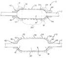
- FIG. 1is a side perspective view of the present stent delivery system shown prior to stent delivery;
- FIG. 2is a side perspective view of the present stent delivery system shown with the inflatable portion in the inflated state during stent delivery;
- FIG. 3is a side perspective view of the present stent delivery system shown subsequent to stent delivery and deflation of the inflatable portion.
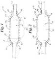
- FIG. 4is a side perspective view of a prior art balloon having cone shaped ends of 45 degree orientation.
- FIG. 5is a side perspective view of a balloon having hemispherical ends.
- FIG. 1shows an embodiment of the present stent delivery system.
- a stent delivery catheterindicated generally at 10 , includes an elongated shaft 12 having an inflatable portion 14 .
- the inflatable portionmay be a balloon or other inflatable device separate from the catheter shaft.
- the balloonmay be attached to the catheter shaft using retaining rings disposed about the ends of the balloon, bonding or welding the balloon to the catheter shaft, or otherwise attaching the balloon and the catheter shaft together.
- the inflatable portion or balloonmay be composed of any thermoplastic polymer or polymers, alone or in combination, in single or multiple layers.
- inflatable portion 14is divided into three portions: a proximal end 16 , a distal end 18 and an elongated body portion 20 which defines the area of the balloon which is between the proximal and distal ends.
- the ends of the balloonhave a rounded construction.
- proximal end 16 and distal end 18are hemispherical in shape.
- the hemispherical shape of the balloon endsprovide an increased length to the ends of at least 11 percent, when compared to a similar balloon equipped with conical ends.
- the increased length of the rounded endsis best explained by an understanding of FIGS. 4 and 5.
- FIG. 4shows a standard prior art balloon 100 , in the inflated state, equipped with ends 102 , 104 which are cone shaped.
- the balloon shownhas a catheter shaft 105 .
- the cone ends 102 , 104form a 45 degree angle with the catheter shaft as shown.
- Vertical base lines 106 , and horizontal base lines 108form a 90 degree angle at their intersection and are depicted in order to illustrate that an equilateral triangle is formed between a given vertical base line, horizontal base line, and the hypotenuse (i.e. each surface of the cone shaped ends 102 , 104 ).
- both vertical base lines 106 and horizontal base lines 108are all given a theoretical length of 1 mm, then as a function of the Pythagorean theorem the respective surfaces of the cone shaped ends 102 , 104 will have a length equivalent to the square root of 2 mm.
- the formula and applicationare as follows:
- FIG. 5the inflatable portion or balloon 14 , as used in the present stent delivery system is shown.
- balloon 14has proximal and distal hemispherical shaped ends 16 , 18 .
- vertical base lines 126 and horizontal base lines 128are given a theoretical length of 1 mm.
- Vertical base lines 126 , and horizontal base lines 128form a 90 degree angle at their intersection and are depicted in order to illustrate that an quarter of a circle is formed between a given vertical base line, horizontal base line, and each surface of the cone shaped ends 16 , 18 .
- the length of each surface of the ends 16 , 18can be determined by applying the formula for the circumference of a circle, and then dividing the result by 4 (i.e 1 ⁇ 4 of the resulting value for each quarter circle).
- the present balloonwill have a ends which provide longer length in the inflated state then compared to a balloon having cone shaped ends oriented at 45 degree angles where both balloons have equivalent base lengths.
- the longer length of balloon ends 16 , 18 when in the inflated stateprovides the present inventive stent delivery system with the capability to draw a stent completely away from a pair of stent retaining sleeves disposed about the margins of the stent as described in detail below.
- the present stent delivery systemcan deliver a stent with improved safety and consistency.
- Balloon 14may be composed of any thermoplastic polymer, or polymers, suitable for use as a medical balloon.
- thermoplastic polymersinclude, but are not limited to: polyethylene teraphtholate (PET), polybutylene teraphtholate (PBT), PEBAXTM, NylonTM, polyurethane, polyester-polyether block copolymer such as ARNITELTM, polyolefin and polyolefin compounds.
- PETpolyethylene teraphtholate
- PBTpolybutylene teraphtholate
- PEBAXTMpolyethylene teraphtholate
- NylonTMpolyurethane
- polyester-polyether block copolymersuch as ARNITELTM
- polyolefin and polyolefin compoundspolyolefin compounds.
- the present balloonmay be manufactured by any means appropriate for manufacture a medical balloon. One such approach involves forming a balloon by stretching and blowing of the balloon from a segment of extrude
- a balloon preformprepared by joining three segments of tubing end-to-end via the use of heat or adhesives.
- proximal end 16 , and distal end 18could be joined to the body portion 20 in the manner described.
- the endsare made from a first polymer material, and the body portion made from a second polymer material.
- Other combinationsmay be possible.
- the balloonmay also be constructed through the well known process of extruding the balloon material into a preform and conventionally blowing the balloon.
- the balloon materialmay be extruded uniformly or may be extruded in sequential segments and subsequently bonded together. All of the methods for constructing the present balloon are discussed in detail in U.S. patent application Ser. No. 09/076252 the entire contents of which are hereby incorporated by reference.
- a stentis shown disposed about body portion 20 .
- the stentmay be self-expanding, such as a NITINOL shape memory stent, or it may be expandable by inflating inflatable portion 14 .
- Stent 30is further characterized as having margins or edges 32 , 34 .
- the margins of the stentmay be of a predetermined length.
- Overlying each of the stent margins 32 , 34is a respective stent retaining sleeve 42 , 44 .
- the stent retaining sleevesare preferably composed of a thermoplastic polymer or polymers characterized as having elastomeric qualities, which may be different or of the same composition as the inflatable portion 14 as described above.
- Each of the stent retaining sleeveshave a catheter attachment portion 46 , 48 and a margin retaining portion 52 , 54 .
- the catheter attachment portions 46 , 48may be attached to the catheter in a variety of manners.
- the catheter attachment portions and the cathetermay be chemically bonded, heat sealed, welded (lap welded, butt welded, laser welded, etc.) or otherwise bonded together.
- Devicessuch as retaining collars or bands may also be disposed around the catheter attachment portions to hold them against the catheter shaft.
- Other methods of attaching stent retaining sleeves to a catheteras may be known to one of ordinary skill in the art may also be employed.
- the margin retaining portions 52 , 54When the inflatable portion or balloon is in the non-inflated state the margin retaining portions 52 , 54 , of the stent retaining sleeves, extend from the catheter shaft and respectively overlie balloon ends 16 and 18 as well as stent margins 32 and 34 as shown in FIG. 1 .
- margin retaining portions 52 , 54When balloon 14 is inflated margin retaining portions 52 , 54 are drawn away from stent margins 32 , 34 , as shown in FIG. 2 .
- ends 16 , 18having a hemispherical shape, the cones will have a sufficient length to allow the margin retaining portions 52 , 54 to be drawn well away from the stent margins 32 , 34 , thereby freeing the stent for delivery when balloon 14 is in the fully inflated state as may be seen in FIG. 2 .
- the stent retaining sleeveswill assist in reducing the radial diameter of the inflatable portion.
- the balloon 14is reduced in diameter by deflation or evacuation of the inflation fluid.
- the elastomeric nature of stent retaining sleeves 42 , 44causes the margin retaining portions 52 , 54 to radially collapse rounded ends 16 , 18 of balloon 14 .
- the rounded shape of ends 16 , 18provides an increased area for margin retaining portions 52 , 54 to press upon, thus providing the present invention with improved collapsibility than compared to a balloon having cone shaped ends and correspondingly shaped sleeves.
- balloon 14will have a profile of sufficiently reduced nature to allow the stent delivery system to be safely and effectively withdrawn from the stent, vessel and subsequent guiding catheter.
Landscapes
- Health & Medical Sciences (AREA)
- Engineering & Computer Science (AREA)
- Biomedical Technology (AREA)
- Cardiology (AREA)
- Oral & Maxillofacial Surgery (AREA)
- Transplantation (AREA)
- Heart & Thoracic Surgery (AREA)
- Vascular Medicine (AREA)
- Life Sciences & Earth Sciences (AREA)
- Animal Behavior & Ethology (AREA)
- General Health & Medical Sciences (AREA)
- Public Health (AREA)
- Veterinary Medicine (AREA)
- Media Introduction/Drainage Providing Device (AREA)
Abstract
Description

Claims (13)
Priority Applications (2)
| Application Number | Priority Date | Filing Date | Title |
|---|---|---|---|
| US09/510,427US6432129B2 (en) | 2000-02-22 | 2000-02-22 | Stent delivery system |
| PCT/US2001/003315WO2001062186A1 (en) | 2000-02-22 | 2001-02-01 | Stent delivery system |
Applications Claiming Priority (1)
| Application Number | Priority Date | Filing Date | Title |
|---|---|---|---|
| US09/510,427US6432129B2 (en) | 2000-02-22 | 2000-02-22 | Stent delivery system |
Publications (2)
| Publication Number | Publication Date |
|---|---|
| US20010027337A1 US20010027337A1 (en) | 2001-10-04 |
| US6432129B2true US6432129B2 (en) | 2002-08-13 |
Family
ID=24030694
Family Applications (1)
| Application Number | Title | Priority Date | Filing Date |
|---|---|---|---|
| US09/510,427Expired - LifetimeUS6432129B2 (en) | 2000-02-22 | 2000-02-22 | Stent delivery system |
Country Status (2)
| Country | Link |
|---|---|
| US (1) | US6432129B2 (en) |
| WO (1) | WO2001062186A1 (en) |
Cited By (46)
| Publication number | Priority date | Publication date | Assignee | Title |
|---|---|---|---|---|
| US6733521B2 (en) | 2001-04-11 | 2004-05-11 | Trivascular, Inc. | Delivery system and method for endovascular graft |
| US20040113731A1 (en)* | 2002-10-09 | 2004-06-17 | David Moyer | Electromagnetic valve system |
| US6761733B2 (en) | 2001-04-11 | 2004-07-13 | Trivascular, Inc. | Delivery system and method for bifurcated endovascular graft |
| US6790224B2 (en)* | 2002-02-04 | 2004-09-14 | Scimed Life Systems, Inc. | Medical devices |
| US20040260379A1 (en)* | 2003-06-23 | 2004-12-23 | Jagger Karl A. | Asymmetric stent delivery system with proximal edge protection and method of manufacture thereof |
| US20060079955A1 (en)* | 2004-10-07 | 2006-04-13 | Scimed Life Systems, Inc. | Non-shortening helical stent |
| US7066951B2 (en) | 2000-02-02 | 2006-06-27 | Trivascular, Inc. | Delivery system and method for expandable intracorporeal device |
| US7122050B2 (en) | 1998-09-30 | 2006-10-17 | Bard Peripheral Vascular, Inc. | Delivery mechanism for implantable stent |
| US20060235501A1 (en)* | 2003-05-23 | 2006-10-19 | Keiji Igaki | Stent supplying device |
| US20070043381A1 (en)* | 2005-08-19 | 2007-02-22 | Icon Medical Corp. | Medical device deployment instrument |
| US20070276468A1 (en)* | 2005-05-24 | 2007-11-29 | Inspiremd Ltd. | Bifurcated stent assemblies |
| US20080172082A1 (en)* | 2006-10-18 | 2008-07-17 | Inspiremd Ltd. | In vivo filter assembly |
| US20090312831A1 (en)* | 2008-06-11 | 2009-12-17 | C. R. Bard, Inc. | Catheter delivery device |
| US20090312830A1 (en)* | 2008-06-17 | 2009-12-17 | Mcnulty Sean | Balloon arc profile control |
| US7651521B2 (en) | 2004-03-02 | 2010-01-26 | Cardiomind, Inc. | Corewire actuated delivery system with fixed distal stent-carrying extension |
| US20100036477A1 (en)* | 2008-08-06 | 2010-02-11 | Boston Scientific Scimed, Inc. | Stent edge protection and methods |
| US7771463B2 (en) | 2003-03-26 | 2010-08-10 | Ton Dai T | Twist-down implant delivery technologies |
| US20100204772A1 (en)* | 2006-10-18 | 2010-08-12 | Asher Holzer | Filter Assemblies |
| US7785361B2 (en) | 2003-03-26 | 2010-08-31 | Julian Nikolchev | Implant delivery technologies |
| US20100241214A1 (en)* | 2006-11-22 | 2010-09-23 | Inspiremd Ltd. | Optimized stent jacket |
| US20100324651A1 (en)* | 2006-10-18 | 2010-12-23 | Asher Holzer | Knitted Stent Jackets |
| US20100324664A1 (en)* | 2006-10-18 | 2010-12-23 | Asher Holzer | Bifurcated Stent Assemblies |
| US20100331956A1 (en)* | 2002-07-22 | 2010-12-30 | Armstrong Joseph R | Endoluminal expansion system |
| US7862602B2 (en) | 2005-11-02 | 2011-01-04 | Biosensors International Group, Ltd | Indirect-release electrolytic implant delivery systems |
| US8016869B2 (en) | 2003-03-26 | 2011-09-13 | Biosensors International Group, Ltd. | Guidewire-less stent delivery methods |
| US8025692B2 (en) | 2001-10-02 | 2011-09-27 | Angiomed Gmbh & Co. Medizintechnik Kg | Stent delivery system |
| US8066755B2 (en) | 2007-09-26 | 2011-11-29 | Trivascular, Inc. | System and method of pivoted stent deployment |
| US8075606B2 (en) | 2001-07-06 | 2011-12-13 | Angiomed Gmbh & Co. Medizintechnik Kg | Delivery system having a rapid pusher assembly for self-expanding stent, and stent exchange configuration |
| US8083789B2 (en) | 2007-11-16 | 2011-12-27 | Trivascular, Inc. | Securement assembly and method for expandable endovascular device |
| US8226701B2 (en) | 2007-09-26 | 2012-07-24 | Trivascular, Inc. | Stent and delivery system for deployment thereof |
| US8241346B2 (en) | 2001-12-20 | 2012-08-14 | Trivascular, Inc. | Endovascular graft and method of delivery |
| US8328861B2 (en) | 2007-11-16 | 2012-12-11 | Trivascular, Inc. | Delivery system and method for bifurcated graft |
| US8475515B2 (en) | 2003-01-15 | 2013-07-02 | Angiomed GmbH & Co., Medizinitechnik KG | Trans-luminal surgical device |
| US8652193B2 (en) | 2005-05-09 | 2014-02-18 | Angiomed Gmbh & Co. Medizintechnik Kg | Implant delivery device |
| US8657870B2 (en) | 2009-06-26 | 2014-02-25 | Biosensors International Group, Ltd. | Implant delivery apparatus and methods with electrolytic release |
| US8663309B2 (en) | 2007-09-26 | 2014-03-04 | Trivascular, Inc. | Asymmetric stent apparatus and method |
| US8956376B2 (en) | 2011-06-30 | 2015-02-17 | The Spectranetics Corporation | Reentry catheter and method thereof |
| US8992595B2 (en) | 2012-04-04 | 2015-03-31 | Trivascular, Inc. | Durable stent graft with tapered struts and stable delivery methods and devices |
| US8998936B2 (en) | 2011-06-30 | 2015-04-07 | The Spectranetics Corporation | Reentry catheter and method thereof |
| US20150245936A1 (en)* | 2009-03-25 | 2015-09-03 | Svelte Medical Systems, Inc. | Stent Delivery Catheter With Balloon Control Bands |
| US9498363B2 (en) | 2012-04-06 | 2016-11-22 | Trivascular, Inc. | Delivery catheter for endovascular device |
| US9814862B2 (en) | 2011-06-30 | 2017-11-14 | The Spectranetics Corporation | Reentry catheter and method thereof |
| US10058440B2 (en) | 2005-05-24 | 2018-08-28 | Inspiremd, Ltd. | Carotid stent apparatus and methods for treatment via body lumens |
| US10159557B2 (en) | 2007-10-04 | 2018-12-25 | Trivascular, Inc. | Modular vascular graft for low profile percutaneous delivery |
| US10583020B2 (en) | 2015-05-27 | 2020-03-10 | Trivascular, Inc. | Balloon assisted endoluminal prosthesis deployment |
| US11931276B2 (en) | 2008-06-11 | 2024-03-19 | C. R. Bard, Inc. | Catheter delivery device |
Families Citing this family (16)
| Publication number | Priority date | Publication date | Assignee | Title |
|---|---|---|---|---|
| US7128756B2 (en) | 2002-05-08 | 2006-10-31 | Abbott Laboratories | Endoprosthesis having foot extensions |
| EP1542616B1 (en) | 2002-09-20 | 2015-04-22 | Endologix, Inc. | Stent-graft with positioning anchor |
| US7625398B2 (en) | 2003-05-06 | 2009-12-01 | Abbott Laboratories | Endoprosthesis having foot extensions |
| US7625401B2 (en) | 2003-05-06 | 2009-12-01 | Abbott Laboratories | Endoprosthesis having foot extensions |
| US8048145B2 (en) | 2004-07-22 | 2011-11-01 | Endologix, Inc. | Graft systems having filling structures supported by scaffolds and methods for their use |
| EP2364676B1 (en)* | 2005-06-30 | 2018-12-19 | Abbott Laboratories | Endoprosthesis having foot extensions |
| JP2009500121A (en) | 2005-07-07 | 2009-01-08 | ネリックス・インコーポレーテッド | System and method for treatment of an intraluminal aneurysm |
| EP2278939B1 (en) | 2008-04-25 | 2021-04-14 | Endologix LLC | Stent graft delivery system |
| EP2299931B1 (en) | 2008-06-04 | 2020-01-08 | Endologix, Inc. | Sealing apparatus |
| US20110276078A1 (en) | 2009-12-30 | 2011-11-10 | Nellix, Inc. | Filling structure for a graft system and methods of use |
| US8801768B2 (en) | 2011-01-21 | 2014-08-12 | Endologix, Inc. | Graft systems having semi-permeable filling structures and methods for their use |
| EP2693980B1 (en) | 2011-04-06 | 2022-07-13 | Endologix LLC | System for endovascular aneurysm treatment |
| US11701127B2 (en) | 2012-03-06 | 2023-07-18 | Accumed Radial Systems, Llc | Hemostasis apparatus and method |
| BR112015022688B1 (en) | 2013-03-14 | 2020-10-06 | Endologix, Inc. | METHOD FOR FORMING A MATERIAL IN SITU THROUGH INCREASING THE VOLUME OF AN EXPANDABLE MEMBER OF A MEDICAL DEVICE |
| WO2015157181A1 (en)* | 2014-04-08 | 2015-10-15 | Stryker Corporation | Implant delivery system |
| CA3075636A1 (en) | 2017-10-04 | 2019-04-11 | Zorion Medical, Inc. | Delivery balloon with retractable retention cuffs |
Citations (8)
| Publication number | Priority date | Publication date | Assignee | Title |
|---|---|---|---|---|
| US4444188A (en)* | 1980-08-15 | 1984-04-24 | Seymour Bazell | Balloon catheter |
| US4950227A (en) | 1988-11-07 | 1990-08-21 | Boston Scientific Corporation | Stent delivery system |
| US5108416A (en)* | 1990-02-13 | 1992-04-28 | C. R. Bard, Inc. | Stent introducer system |
| US5403341A (en) | 1994-01-24 | 1995-04-04 | Solar; Ronald J. | Parallel flow endovascular stent and deployment apparatus therefore |
| WO1996003092A1 (en) | 1994-07-28 | 1996-02-08 | Brun, Heidi, M. | A flexible expandable stent |
| US5653736A (en) | 1995-01-19 | 1997-08-05 | Cordis Corporation | Carrier balloon for a stent assembly with radiation-shielding capabilities |
| US5772674A (en)* | 1997-03-31 | 1998-06-30 | Nakhjavan; Fred K. | Catheter for removal of clots in blood vessels |
| US5810871A (en)* | 1997-04-29 | 1998-09-22 | Medtronic, Inc. | Stent delivery system |
- 2000
- 2000-02-22USUS09/510,427patent/US6432129B2/ennot_activeExpired - Lifetime
- 2001
- 2001-02-01WOPCT/US2001/003315patent/WO2001062186A1/enactiveApplication Filing
Patent Citations (8)
| Publication number | Priority date | Publication date | Assignee | Title |
|---|---|---|---|---|
| US4444188A (en)* | 1980-08-15 | 1984-04-24 | Seymour Bazell | Balloon catheter |
| US4950227A (en) | 1988-11-07 | 1990-08-21 | Boston Scientific Corporation | Stent delivery system |
| US5108416A (en)* | 1990-02-13 | 1992-04-28 | C. R. Bard, Inc. | Stent introducer system |
| US5403341A (en) | 1994-01-24 | 1995-04-04 | Solar; Ronald J. | Parallel flow endovascular stent and deployment apparatus therefore |
| WO1996003092A1 (en) | 1994-07-28 | 1996-02-08 | Brun, Heidi, M. | A flexible expandable stent |
| US5653736A (en) | 1995-01-19 | 1997-08-05 | Cordis Corporation | Carrier balloon for a stent assembly with radiation-shielding capabilities |
| US5772674A (en)* | 1997-03-31 | 1998-06-30 | Nakhjavan; Fred K. | Catheter for removal of clots in blood vessels |
| US5810871A (en)* | 1997-04-29 | 1998-09-22 | Medtronic, Inc. | Stent delivery system |
Cited By (82)
| Publication number | Priority date | Publication date | Assignee | Title |
|---|---|---|---|---|
| US8852266B2 (en) | 1998-09-30 | 2014-10-07 | Bard Peripheral Vascular, Inc. | Delivery mechanism for implantable stent |
| US7122050B2 (en) | 1998-09-30 | 2006-10-17 | Bard Peripheral Vascular, Inc. | Delivery mechanism for implantable stent |
| US7338518B2 (en) | 2000-02-02 | 2008-03-04 | Boston Scientific Santa Rosa Corp. | Delivery system and method for expandable intracorporeal device |
| US7066951B2 (en) | 2000-02-02 | 2006-06-27 | Trivascular, Inc. | Delivery system and method for expandable intracorporeal device |
| US6761733B2 (en) | 2001-04-11 | 2004-07-13 | Trivascular, Inc. | Delivery system and method for bifurcated endovascular graft |
| US6733521B2 (en) | 2001-04-11 | 2004-05-11 | Trivascular, Inc. | Delivery system and method for endovascular graft |
| US8075606B2 (en) | 2001-07-06 | 2011-12-13 | Angiomed Gmbh & Co. Medizintechnik Kg | Delivery system having a rapid pusher assembly for self-expanding stent, and stent exchange configuration |
| US8025692B2 (en) | 2001-10-02 | 2011-09-27 | Angiomed Gmbh & Co. Medizintechnik Kg | Stent delivery system |
| US8241346B2 (en) | 2001-12-20 | 2012-08-14 | Trivascular, Inc. | Endovascular graft and method of delivery |
| US8864814B2 (en) | 2001-12-20 | 2014-10-21 | Trivascular, Inc. | Method of delivering advanced endovascular graft and system |
| US6790224B2 (en)* | 2002-02-04 | 2004-09-14 | Scimed Life Systems, Inc. | Medical devices |
| US8177832B2 (en) | 2002-07-22 | 2012-05-15 | W. L. Gore & Associates, Inc. | Endoluminal expansion system |
| US20100331956A1 (en)* | 2002-07-22 | 2010-12-30 | Armstrong Joseph R | Endoluminal expansion system |
| US20040113731A1 (en)* | 2002-10-09 | 2004-06-17 | David Moyer | Electromagnetic valve system |
| US8568467B2 (en) | 2003-01-15 | 2013-10-29 | Angiomed Gmbh & Co. Medizintechnik Kg | Trans-luminal surgical device |
| US8475515B2 (en) | 2003-01-15 | 2013-07-02 | Angiomed GmbH & Co., Medizinitechnik KG | Trans-luminal surgical device |
| US7785361B2 (en) | 2003-03-26 | 2010-08-31 | Julian Nikolchev | Implant delivery technologies |
| US8016869B2 (en) | 2003-03-26 | 2011-09-13 | Biosensors International Group, Ltd. | Guidewire-less stent delivery methods |
| US7771463B2 (en) | 2003-03-26 | 2010-08-10 | Ton Dai T | Twist-down implant delivery technologies |
| US20060235501A1 (en)* | 2003-05-23 | 2006-10-19 | Keiji Igaki | Stent supplying device |
| US8784466B2 (en)* | 2003-05-23 | 2014-07-22 | Kabushikikaisha Igaki Iryo Sekkei | Stent delivery system |
| US8318078B2 (en) | 2003-06-23 | 2012-11-27 | Boston Scientific Scimed, Inc. | Asymmetric stent delivery system with proximal edge protection and method of manufacture thereof |
| US20040260379A1 (en)* | 2003-06-23 | 2004-12-23 | Jagger Karl A. | Asymmetric stent delivery system with proximal edge protection and method of manufacture thereof |
| US7651521B2 (en) | 2004-03-02 | 2010-01-26 | Cardiomind, Inc. | Corewire actuated delivery system with fixed distal stent-carrying extension |
| US20060079955A1 (en)* | 2004-10-07 | 2006-04-13 | Scimed Life Systems, Inc. | Non-shortening helical stent |
| US7914570B2 (en) | 2004-10-07 | 2011-03-29 | Boston Scientific Scimed, Inc. | Non-shortening helical stent |
| US8652193B2 (en) | 2005-05-09 | 2014-02-18 | Angiomed Gmbh & Co. Medizintechnik Kg | Implant delivery device |
| US8961586B2 (en) | 2005-05-24 | 2015-02-24 | Inspiremd Ltd. | Bifurcated stent assemblies |
| US10058440B2 (en) | 2005-05-24 | 2018-08-28 | Inspiremd, Ltd. | Carotid stent apparatus and methods for treatment via body lumens |
| US10070977B2 (en) | 2005-05-24 | 2018-09-11 | Inspire M.D. Ltd | Stent apparatuses for treatment via body lumens and methods of use |
| US10932926B2 (en) | 2005-05-24 | 2021-03-02 | Inspiremd Ltd. | Stent assembly and methods for treatment via body lumens |
| US20070276468A1 (en)* | 2005-05-24 | 2007-11-29 | Inspiremd Ltd. | Bifurcated stent assemblies |
| US20070043381A1 (en)* | 2005-08-19 | 2007-02-22 | Icon Medical Corp. | Medical device deployment instrument |
| US7862602B2 (en) | 2005-11-02 | 2011-01-04 | Biosensors International Group, Ltd | Indirect-release electrolytic implant delivery systems |
| US8900285B2 (en) | 2005-11-02 | 2014-12-02 | Biosensors International Group, Ltd. | Covering electrolytic restraint implant delivery systems |
| US8974509B2 (en) | 2005-11-02 | 2015-03-10 | Biosensors International Group, Ltd. | Pass-through restraint electrolytic implant delivery systems |
| US8579954B2 (en) | 2005-11-02 | 2013-11-12 | Biosensors International Group, Ltd. | Untwisting restraint implant delivery system |
| US8273116B2 (en) | 2005-11-02 | 2012-09-25 | Biosensors International Group, Ltd. | Indirect-release electrolytic implant delivery systems |
| US20100324651A1 (en)* | 2006-10-18 | 2010-12-23 | Asher Holzer | Knitted Stent Jackets |
| US9132261B2 (en) | 2006-10-18 | 2015-09-15 | Inspiremd, Ltd. | In vivo filter assembly |
| US10137015B2 (en) | 2006-10-18 | 2018-11-27 | Inspiremd Ltd. | Knitted stent jackets |
| US20080172082A1 (en)* | 2006-10-18 | 2008-07-17 | Inspiremd Ltd. | In vivo filter assembly |
| US20100204772A1 (en)* | 2006-10-18 | 2010-08-12 | Asher Holzer | Filter Assemblies |
| US20100324664A1 (en)* | 2006-10-18 | 2010-12-23 | Asher Holzer | Bifurcated Stent Assemblies |
| US8043323B2 (en) | 2006-10-18 | 2011-10-25 | Inspiremd Ltd. | In vivo filter assembly |
| US9526644B2 (en) | 2006-11-22 | 2016-12-27 | Inspiremd, Ltd. | Optimized drug-eluting stent assembly methods |
| US10406008B2 (en) | 2006-11-22 | 2019-09-10 | Inspiremd, Ltd. | Optimized stent jacket having single fiber mesh |
| US9782281B2 (en) | 2006-11-22 | 2017-10-10 | Inspiremd, Ltd. | Stent-mesh assembly and methods |
| US20100241214A1 (en)* | 2006-11-22 | 2010-09-23 | Inspiremd Ltd. | Optimized stent jacket |
| US11051959B2 (en) | 2006-11-22 | 2021-07-06 | Inspiremd, Ltd. | Intravascular aneurysm treatment device and methods |
| US10406006B2 (en) | 2006-11-22 | 2019-09-10 | Inspiremd, Ltd. | Methods of providing optimized drug-eluting stent assemblies |
| US10070976B2 (en) | 2006-11-22 | 2018-09-11 | Inspiremd Ltd. | Optimized stent jacket |
| US9132003B2 (en) | 2006-11-22 | 2015-09-15 | Inspiremd, Ltd. | Optimized drug-eluting stent assembly |
| US8066755B2 (en) | 2007-09-26 | 2011-11-29 | Trivascular, Inc. | System and method of pivoted stent deployment |
| US8226701B2 (en) | 2007-09-26 | 2012-07-24 | Trivascular, Inc. | Stent and delivery system for deployment thereof |
| US8663309B2 (en) | 2007-09-26 | 2014-03-04 | Trivascular, Inc. | Asymmetric stent apparatus and method |
| US12016766B2 (en) | 2007-10-04 | 2024-06-25 | Trivascular, Inc. | Modular vascular graft for low profile percutaneous delivery |
| US10159557B2 (en) | 2007-10-04 | 2018-12-25 | Trivascular, Inc. | Modular vascular graft for low profile percutaneous delivery |
| US10682222B2 (en) | 2007-10-04 | 2020-06-16 | Trivascular, Inc. | Modular vascular graft for low profile percutaneous delivery |
| US8328861B2 (en) | 2007-11-16 | 2012-12-11 | Trivascular, Inc. | Delivery system and method for bifurcated graft |
| US8083789B2 (en) | 2007-11-16 | 2011-12-27 | Trivascular, Inc. | Securement assembly and method for expandable endovascular device |
| US11931276B2 (en) | 2008-06-11 | 2024-03-19 | C. R. Bard, Inc. | Catheter delivery device |
| US11109990B2 (en) | 2008-06-11 | 2021-09-07 | C. R. Bard, Inc. | Catheter delivery device |
| US20090312831A1 (en)* | 2008-06-11 | 2009-12-17 | C. R. Bard, Inc. | Catheter delivery device |
| US9750625B2 (en) | 2008-06-11 | 2017-09-05 | C.R. Bard, Inc. | Catheter delivery device |
| US20090312830A1 (en)* | 2008-06-17 | 2009-12-17 | Mcnulty Sean | Balloon arc profile control |
| US20100036477A1 (en)* | 2008-08-06 | 2010-02-11 | Boston Scientific Scimed, Inc. | Stent edge protection and methods |
| US8715331B2 (en) | 2008-08-06 | 2014-05-06 | Boston Scientific Scimed, Inc. | Stent edge protection and methods |
| US9387103B2 (en)* | 2009-03-25 | 2016-07-12 | Svelte Medical Systems, Inc. | Stent delivery catheter with balloon control bands |
| US20150245936A1 (en)* | 2009-03-25 | 2015-09-03 | Svelte Medical Systems, Inc. | Stent Delivery Catheter With Balloon Control Bands |
| US8657870B2 (en) | 2009-06-26 | 2014-02-25 | Biosensors International Group, Ltd. | Implant delivery apparatus and methods with electrolytic release |
| US8956376B2 (en) | 2011-06-30 | 2015-02-17 | The Spectranetics Corporation | Reentry catheter and method thereof |
| US10183151B2 (en) | 2011-06-30 | 2019-01-22 | Spectranetics Corporation | Reentry catheter and method thereof |
| US10603467B2 (en) | 2011-06-30 | 2020-03-31 | The Spectranetics Corporation | Reentry catheter and method thereof |
| US9814862B2 (en) | 2011-06-30 | 2017-11-14 | The Spectranetics Corporation | Reentry catheter and method thereof |
| US10709872B2 (en) | 2011-06-30 | 2020-07-14 | The Spectranetics Corporation | Reentry catheter and method thereof |
| US9775969B2 (en) | 2011-06-30 | 2017-10-03 | The Spectranetics Corporation | Reentry catheter and method thereof |
| US9408998B2 (en) | 2011-06-30 | 2016-08-09 | The Spectranetics Corporation | Reentry catheter and method thereof |
| US8998936B2 (en) | 2011-06-30 | 2015-04-07 | The Spectranetics Corporation | Reentry catheter and method thereof |
| US8992595B2 (en) | 2012-04-04 | 2015-03-31 | Trivascular, Inc. | Durable stent graft with tapered struts and stable delivery methods and devices |
| US9498363B2 (en) | 2012-04-06 | 2016-11-22 | Trivascular, Inc. | Delivery catheter for endovascular device |
| US10583020B2 (en) | 2015-05-27 | 2020-03-10 | Trivascular, Inc. | Balloon assisted endoluminal prosthesis deployment |
Also Published As
| Publication number | Publication date |
|---|---|
| WO2001062186A1 (en) | 2001-08-30 |
| US20010027337A1 (en) | 2001-10-04 |
Similar Documents
| Publication | Publication Date | Title |
|---|---|---|
| US6432129B2 (en) | Stent delivery system | |
| US6432080B2 (en) | Stent securement by balloon modification | |
| US20060161240A1 (en) | Catheter for controlled stent delivery | |
| US6432130B1 (en) | Fully sheathed balloon expandable stent delivery system | |
| US6387118B1 (en) | Non-crimped stent delivery system | |
| US6733520B2 (en) | Sandwich striped sleeve for stent delivery | |
| US6530948B1 (en) | Segmented balloon delivery system | |
| US6881216B2 (en) | Balloon catheter with stent securement means | |
| JP3968444B2 (en) | Stent delivery mechanism with stent fixation device | |
| US6478814B2 (en) | Stent securement sleeves and optional coatings and methods of use | |
| US20020120321A1 (en) | Stent retention mechanism | |
| US8206431B2 (en) | Stent body sock | |
| US20020072789A1 (en) | Soc lubricant filler port | |
| JPH10507667A (en) | Balloon expandable stent / graft delivery device | |
| EP1152711A1 (en) | Bifurcation stent delivery system | |
| CN117100470A (en) | Vascular stent | |
| US20060229701A1 (en) | Apparatus for use with expandable stents |
Legal Events
| Date | Code | Title | Description |
|---|---|---|---|
| AS | Assignment | Owner name:SCIMED LIFE SYSTEMS, INC., MINNESOTA Free format text:ASSIGNMENT OF ASSIGNORS INTEREST;ASSIGNOR:DI CAPRIO, FERNANDO;REEL/FRAME:010631/0261 Effective date:20000119 | |
| AS | Assignment | Owner name:SCIMED LIFE SYSTEMS, INC., MINNESOTA Free format text:ASSIGNMENT OF ASSIGNORS INTEREST;ASSIGNOR:DICAPRIO, FERNANDO;REEL/FRAME:010883/0157 Effective date:20000508 | |
| STCF | Information on status: patent grant | Free format text:PATENTED CASE | |
| FPAY | Fee payment | Year of fee payment:4 | |
| AS | Assignment | Owner name:BOSTON SCIENTIFIC SCIMED, INC., MINNESOTA Free format text:CHANGE OF NAME;ASSIGNOR:SCIMED LIFE SYSTEMS, INC.;REEL/FRAME:018505/0868 Effective date:20050101 Owner name:BOSTON SCIENTIFIC SCIMED, INC.,MINNESOTA Free format text:CHANGE OF NAME;ASSIGNOR:SCIMED LIFE SYSTEMS, INC.;REEL/FRAME:018505/0868 Effective date:20050101 | |
| FPAY | Fee payment | Year of fee payment:8 | |
| FPAY | Fee payment | Year of fee payment:12 |