US6431505B2 - IV pole - Google Patents
IV poleDownload PDFInfo
- Publication number
- US6431505B2 US6431505B2US09/816,581US81658101AUS6431505B2US 6431505 B2US6431505 B2US 6431505B2US 81658101 AUS81658101 AUS 81658101AUS 6431505 B2US6431505 B2US 6431505B2
- Authority
- US
- United States
- Prior art keywords
- pole
- plunger
- recited
- holding device
- collar
- Prior art date
- Legal status (The legal status is an assumption and is not a legal conclusion. Google has not performed a legal analysis and makes no representation as to the accuracy of the status listed.)
- Expired - Lifetime
Links
Images


Classifications
- A—HUMAN NECESSITIES
- A61—MEDICAL OR VETERINARY SCIENCE; HYGIENE
- A61M—DEVICES FOR INTRODUCING MEDIA INTO, OR ONTO, THE BODY; DEVICES FOR TRANSDUCING BODY MEDIA OR FOR TAKING MEDIA FROM THE BODY; DEVICES FOR PRODUCING OR ENDING SLEEP OR STUPOR
- A61M5/00—Devices for bringing media into the body in a subcutaneous, intra-vascular or intramuscular way; Accessories therefor, e.g. filling or cleaning devices, arm-rests
- A61M5/14—Infusion devices, e.g. infusing by gravity; Blood infusion; Accessories therefor
- A61M5/1414—Hanging-up devices
- A61M5/1415—Stands, brackets or the like for supporting infusion accessories
- A—HUMAN NECESSITIES
- A61—MEDICAL OR VETERINARY SCIENCE; HYGIENE
- A61G—TRANSPORT, PERSONAL CONVEYANCES, OR ACCOMMODATION SPECIALLY ADAPTED FOR PATIENTS OR DISABLED PERSONS; OPERATING TABLES OR CHAIRS; CHAIRS FOR DENTISTRY; FUNERAL DEVICES
- A61G7/00—Beds specially adapted for nursing; Devices for lifting patients or disabled persons
- A61G7/05—Parts, details or accessories of beds
- A61G7/0503—Holders, support devices for receptacles, e.g. for drainage or urine bags
- A—HUMAN NECESSITIES
- A61—MEDICAL OR VETERINARY SCIENCE; HYGIENE
- A61G—TRANSPORT, PERSONAL CONVEYANCES, OR ACCOMMODATION SPECIALLY ADAPTED FOR PATIENTS OR DISABLED PERSONS; OPERATING TABLES OR CHAIRS; CHAIRS FOR DENTISTRY; FUNERAL DEVICES
- A61G1/00—Stretchers
Definitions
- This inventionrelates to an IV pole and, more particularly, to an IV pole with a holding assembly that safely secures intravenous fluid containers to the top of the IV pole.
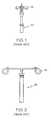
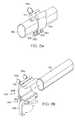
- FIGS. 1 and 2Two common types of IV support arms or brackets used to support or hang IV containers from a conventional IV pole 10 are illustrated by FIGS. 1 and 2.
- the first common bracket-typeis a hook assembly 12 , such as disclosed by U.S. Pat. Nos. 5,095,418, and 5,407,163.
- the second common bracket-typeis a looped wire assembly 14 , such as disclosed by U.S. Pat. Nos. 5,135,191, and 5,772,162, and as shown by FIG. 2
- the IV pole 10is mounted directly to an emergency stretcher.
- having one of the above-mentioned common bracket-types 12 or 14may cause the IV pole 10 to snag on an obstruction due to the protruding and/or hooked shape.
- a delay in evacuating a patient carried on the emergency stretchermay ensue if it is necessary to unhooking the bracket from the obstruction.
- catching the bracket on an obstructionmay result in damaging the IV fluid container hung thereon.
- having one of the mentioned bracket-typesmay cause physically injury to an inattentive technician, such as for example, by being caught in the eye with the bracket due to the bracket's protruding shape.
- an IV polewith a holding assembly that secures intravenous fluid containers thereon, and which minimizes the chances of the IV pole snagging on an obstruction.
- an IV polecomprising a holding assembly at a first end and a docking assembly at a second end.
- the holding assemblycomprises a head and a plunger.
- the head on an upper portionincludes at least two opposed upwardly extending projections.
- the projectionsare shaped and sized such that IV fluid containers may be hung thereon.
- a guide holeis provided by the head in the area of the upper portion between the projections.
- a lower portion of the plungeris mounted axially and slidably within the guide hole, wherein the plunger is movable between an extended position and a retracted position that secures the IV fluid containers to the IV pole.
- the smooth profile of the head and plungergreatly reduces the risk of the IV pole getting snagged on an obstruction or causing injury to rescue personnel.
- the docking assemblypermits the IV pole to be removably secured to a docking port provided to a structural member of a structure supporting a patient. Additionally, the docking assembly permits the IV pole to be lowered to a stowed position, if desired.
- an upper portion of the plungerIn the extended position, an upper portion of the plunger is held a distance above the height of the projections to allow IV fluid containers to be hung upon the projections. Pushing downwardly on the plunger's upper portion vertically moves the plunger within the guide hole to place the plunger in a retracted position. In the retracted position, the underside of the plunger's upper portion is proximate to the projections such that removal of IV fluid containers hung on the projections is prevented.
- Various mechanismssuch as a spring or a diaphragm, may be used to maintain and/or move the plunger to the extended and retracted positions. Accordingly, in certain embodiments of the invention, the plunger may be manually and/or automatically moveable between the retracted and extended positions.
- a holding devicefor securing at least one intravenous fluid supply to a fixture.
- the holding devicecomprises a head having a proximate end portion configured to support the at least one intravenous fluid supply, and a distal end portion configured to be mounted to the fixture.
- the headdefines an internal chamber and a guide hole provided in the proximate end portion, wherein the chamber is in communication with the guide hole.
- the holding devicefurther comprises a plunger having a cap portion. The plunger slidably mounts within the chamber and extends through the guide hole.
- the plungeris operable between an extended position in which the cap potion of the plunger extends a distance above the proximate end portion of the head and a retracted position in which the cap portion secures the at least one intravenous fluid supply to the holding device.
- an IV polefor supporting fluid containers above a structure.
- the IV polecomprises an elongated pole having a first end and a second end, and a holding device mounted to the first end.
- the holding devicehas upwardly extending projections and a plunger with a cap portion.
- the plungeris movable between an extended position, in which the cap portion is a distance from the projection such that the fluid containers may be hung upon the projections, and a retracted position in which the cap portion is in close proximity to the projections such that the hung fluid containers are releasably secure upon the projections.
- the IV polefurther comprises a support mounted at the second end for holding the IV pole in an upright condition.
- an IV polefor supporting fluid containers above a structure.
- the IV polecomprises an elongated pole having a first end and a second, a collar with an integral dovetail base, a docking port provided to the structure and having an oppositely shaped channel configured to slidably receive the dovetail base of the collar.
- the collarreleasably secured to the docking port.
- the IV polefurther comprises a mounting plug having first and second ends, the first end of the mounting plug mounted to the first end of the pole, the second end of the mounting plug rotatably mounted to the collar such that the IV pole is movable between an upright condition and a stowed condition.
- FIG. 1is a perspective view of a first-type prior art holding assembly
- FIG. 2is side view of a second-type prior art holding assembly
- FIG. 3is front view of an embodiment of a holding assembly of an IV pole according to the present invention shown in an open position;
- FIG. 4is front view of the holding assembly of FIG. 3, partially cut away to show the internal components, and in a closed position;
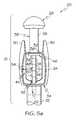
- FIGS. 5 a and 5 bare back and side views, respectively, illustrating other embodiments of a holding assembly of an IV pole according to the present invention, and partially cut-away showing their internal components;
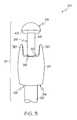
- FIG. 6is a front view of a holding assembly of an IV pole according to the present invention in a closed position
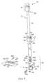
- FIG. 7is a perspective view, partially exploded, of an IV pole according to the present invention in an upright position
- FIG. 8is a perspective view of the IV pole of FIG. 7 shown in a stowed position
- FIGS. 9 a and 9 bare perspective views of docking port/clamping arrangements of an IV pole according to the present invention.
- FIG. 10is a perspective view of another embodiment of an IV pole according to the present invention.
- FIG. 11is a perspective view of still another embodiment of an IV pole according to the present invention.
- a first embodiment of the holding device 21includes a head 24 , and a plunger 26 with a cap portion 28 .
- the head 24includes at least a pair of projections 30 opposed two each other and integrally formed with the head 24 .
- the pair of projections 30extends upwardly from a land area 32 of the head 24 and are shaped and sized to provide attachment points such that conventional IV fluid containers may be hung thereon.
- the head 24further includes a butt portion 34 by which the head 24 mounts to the pole 22 with a tube and butt engagement, as illustrated by FIG. 4 .
- the head 24may mount to the pole 22 with a male and female engagement, wherein a male extension of the head 24 maybe inserted into the inner diameter of the pole 22 .
- a plunger guide hole 36is formed within the land area 32 of the head 24 between the projections 30 .
- a stem portion 38 of the plunger 26is slidably mounted within the plunger guide hole 36 , wherein the plunger is movable between an extended position, illustrate by FIG. 3, and a retracted position, illustrated by FIG. 4 .
- the cap portion 28 of the plunger 26In the extended position, the cap portion 28 of the plunger 26 is held a distance above the height of the projections 30 to allow IV fluid containers to be hung upon the projections. Pushing downwardly on the cap portion 28 , vertically moves the stem portion 38 of the plunger 26 within the plunger guide hole 36 to place the plunger in the retracted position. In the retracted position, a seating surface 40 of the cap portion 28 is proximate to the projections 30 such that removal of IV fluid containers hung on the projections is substantially prevented. It is to be appreciated that the holding device 21 provides for a safer holding arrangement due to the holding device's smooth circumferential profile and the protected vertical attachment points, which minimizes the chance of the upper portion of the IV pole 20 getting snagged on an obstacle during transport.
- Various actuator mechanismsmay be used to maintain and/or move the plunger 26 of the holding device 21 to the extended and retracted positions.
- the plunger 26is conventionally mounted at an end to a flexible membrane 42 .
- the flexible membrane 42is housed within a chamber 44 of the head 24 that is in communication with the plunger guide hole 36 .
- the membrane 42is flexibly deformable to an up position (not shown) and a down position as illustrated, which maintains the plunger 26 in the retracted position. Deforming the membrane 42 to the up position maintains the plunger 26 in the extended position illustrated by FIG. 3 . Manually pushing or pulling on the cap portion 26 deforms the membrane 42 , and situates the plunger 26 in the retracted and extended position, respectively.
- FIGS. 5 a , 5 b , and 6a pop-up feature for the plunger 26 will be described.
- the major difference between these embodimentsis the manner by which the plunger 26 is retained or latched in the retracted position by an engagement member. It is to be appreciated that for other embodiments other latching methods may be used.
- FIGS. 5 a , 5 b , and 6the same features that were mentioned in regards to the embodiment of FIGS. 3 and 4, are labeled with like numbers, and for convenience, only the differences in this embodiment will be discussed.
- the plunger 26is part of a spring-loaded plunger subassembly.
- the plunger 26is mounted to a plate portion 46 of a guide rod 48 and is slidable with the guide rod against the bias of a guide rod spring 50 .
- the plate portion 46in addition to supporting the plunger 26 , is sized such that it acts as stop preventing the stem portion 38 of the plunger 26 to exit completely from at least the plunger guide hole 36 , which is best shown by FIG. 5 a .
- the guide rod spring 50is sized such that it is accommodated in chamber 44 and retained on the guide rod 48 between the plate portion 46 and a guide rod hole 52 .
- the guide rod spring 50is accommodated in a recess provided in the butt portion 34 of the head 24 such that the plate portion 46 of the guide rod 52 retracts in close proximity to the butt portion 34 within the chamber 44 .
- the guide rod hole 52is provided in the butt portion 34 of the head 24 in axial alignment with the plunger guide hole 36 .
- the guide rod 48extends from the guide rod-hole 52 coaxially through the spring 50 to the plunger 26 . With the plunger 26 in the extended position, a portion of the guide rod 48 remains positioned in the guide rod hole 52 , which is illustrated by the dashed-lines in FIG. 5 a.
- the plunger 26 and guide rod 48are slidably movable against the bias of the guide rod spring 50 .
- manually compressing the guide rod spring 50by pushing on the cap portion 28 of the plunger 26 , engages the plate portion 46 of the guide rod 48 with a latching projection 54 provided on the interior surface of a push-button 56 .
- the push-button 56is mounted pivotally to the head 24 and biased against a spring (not shown) toward a retaining position.
- the latching projection 54includes a sloping ridge 58 and an undercut 60 .
- the sloping ridge 58is angled such that the plate portion 46 of the guide rod 48 may slide over and slightly move the latching projection 54 away as the guide rod spring 50 is compressed with minimal resistance.
- the push-button 56retains the plunger 26 in the retracted position with the plate portion 46 engaged by the undercut 60 as illustrated by FIG. 6 .
- the undercut 60 of the latching projection 54moves away from the plate portion 46 , releasing the plunger to pop-up to the extended position.
- a thumb depression 62may be provided to the exterior surface of the push button 56 for more convenient gripping.
- the plate portion 46 of the guide rod 48is provided with a perimeter groove 64 .
- the latching projection 54 of the push-buttonis accommodated in a horizontal through-bore 66 that opens in the cavity 44 of head 24 .
- the latch projection 54is biased against a spring 68 , which maintains the latching projection 54 engaged in the groove 64 of the plate portion 46 holding the plunger 26 in the illustrated retracted position. Accordingly, pressing the push-button moves the latching projection 54 from the retaining position to a release position, which by releasing the guide rod spring 50 permits the plunger 26 to pop-up to the extended position as illustrated by FIG. 6 .
- the cap portion 28 of the plunger 26is held a length above the height of the projections 30 to allow IV fluid containers to be hung upon the projections.
- Pushing down on the cap 28will place the plunger 26 in the retracted position (FIG. 6) with the latching projection 54 of the push-button 56 releasably engaging the plate portion 46 of the guide rod 48 , thereby resetting the pop-up feature of the holding device 21 .
- the cap portion 28In the retracted position, the cap portion 28 either rests or is proximate to the projections 30 securing the IV fluid containers therein. Pressing the push-button, releases the latching projection 54 thereby springing the plunger 26 , by the spring 50 expanding, to the extended position.
- the holding device 21is provided at the end 23 of the elongated pole 22 .
- the elongated pole 22comprises an inner tube 70 , an outer tube 72 , a manually operable adjusting sleeve 74 , and a socket assembly 76 located at the lower end of the outer tube 72 .
- the outside diameter of the inner tube 70is slightly smaller than the inside diameter of the outer tube 72 thereby permitting the inner tube to slide freely within the outer tube.
- the adjustable sleeve 74 at a lower portion 78is mounted over the upper end of the outer tube 72 .
- An upper portion 80 of the adjustable sleeve 74is flexible along a portion of its circumference due to a slit 82 defining the upper portion into a pair of flexible radial arms 84 and 86 .
- a lever 88is pivotally mounted to the free ends of the arms 84 , 86 and is used to releasably secure the inner tube 70 in place when located in a first position substantially parallel to the outer tube 72 .
- Rotating the lever 88 back down to the first positiondraws the arms 84 and 86 of the sleeve 74 closer together thereby squeezing the inner diameter of the upper portion 80 of the sleeve 74 tightly against the outer circumference of the inner tube 70 securing the tube in place.
- the adjustable sleeve 74is used to releasably secure the inner tube 70 in a selected vertical position with respect to the outer tube 72 .
- the socket assembly 76which supports the pole 22 by its lower end in at least an upright condition, comprises a mounting plug 90 , and a generally cylindrical collar 92 with preferably an integral dovetail base 94 .
- a mounting plug 90for example a stand, may be used to support the IV pole 20 in the upright condition.
- the collar 92has a cutout 96 extending into it from its upper edge diametrically across the collar.
- the cutout 96is generally concave in shape and defines a pair of opposed walls 98 .
- a bolt 100is disposed in a pair of first holes 102 provided in the opposed walls 98 at a location above the bottom of the cutout such that the shank of the bolt extends approximately diametrically across the collar at approximately the midsection of the cutout.
- the mounting plug 90has near its center a radially outwardly projecting annular flange 104 . Extending upwardly from the annular flange 104 is a very short cylindrical stub 106 having an outside diameter substantially equal to the inside diameter of the lower end of the outer tube 72 . The stub 106 is disposed within the lower end of outer tube 72 such that the flange 104 is disposed against the lower end of the outer tube 72 .
- the mounting plug 90also includes an elongate projection 108 that extends downwardly from the flange 104 .
- the projectionis generally rectangular, and has a width that is slightly less than the distance between the opposed walls 98 of the collar 92 .
- the outer edges 110 of the projection 108is slightly rounded, and the projection 108 has a lengthwise slot 112 opening transversely through it such that the shank of the bolt 100 is slidably received within the slot.
- a first securing pin 114 ais disposed in a second pair of holes 116 . It is to be appreciated that the hole 116 on the unshown side is the same.
- the holes 116are provided in the opposed walls 98 in a location below the first pair of holes 102 and above the bottom of the cutout 92 such that the shank of the pin 114 a may pass through the slot 112 of the plug 90 with the flange 104 resting against the upper edge of the collar 92 . Accordingly, cooperation of bolt 100 , the pin 114 a , and slot 112 prevents rotation of the outer tube 72 .
- the dovetail base 94releasably mounts to a docking port 118 by sliding the collar 92 into an oppositely shaped mounting socket 120 .
- the docking port 118is mounted directly to a structural member 122 , such as a side rail 125 of a stretcher or emergency cot, as illustrated in FIG. 8 .
- a support bracket 124that easily clips onto the side rail 125 with a flexible C-clamp portion 127 may be used to provide extra support for the IV pole 20 when folded down parallel to the structural member in a stowed condition.
- FIGS. 9 a and 9 bembodiments of removably providing the docking port 118 to the structural member 112 according to the present invention are shown.
- the docking port 118is provided integral to an O-type clamping arrangement 126 .
- the O-type clamping arrangement 126is formed of two halves 128 and 130 that interlock via a tongue and groove fitting 132 , and held tightly on the structural member 112 by a pair of bolts 134 .
- the advantage of this type of arrangementis the docking port 118 may be retrofitted and provided semi-permanently to structural members 112 of a structure, such as for example, various emergency cots, stretchers, vehicles, crash carts, hospital beds, and the like.
- the docking port 118is provided integral to a C-type clamp device 136 that permits the docking port 118 to be slidably engaged onto the structural member 112 .
- Moving a handle 138 from a first position, shown by FIG. 9 b , to a second position, indicated by a dashed-line,will cause a holding surface 140 of the C-type clamp device 136 to lift and to contact firmly against the structural member 112 thereby releasably securing the docking port 118 in place.
- An upper portion 142 of the C-type clamp 136pivots relative to a lower portion 144 such that the C-type clamp may be easily removed from the structural member by positioning the handle 138 in the first position and pivoting the first portion 142 away from the structural member 112 relative to the lower portion 144 .
- the advantage of such a clamping deviceis that the docking port may be easily and conveniently provided to and repositioned on structural members of various types of emergency cots, stretcher, crash carts, transport vehicles, hospital bed and the like.
- FIG. 10another embodiment of an IV pole 20 according to the present invention is shown.
- the dovetail support assembly 76is provided such that the docking port 118 as previously mentioned releasably secures the IV pole 20 to the structural member 112 .
- the support member 146provides an integral cross bracket portion 148 which mat be used to hang intravenous fluid containers and other medical equipment.
- a tubular bar 150is provided which spans between two structural members 112 a and 112 b , as illustrated by FIG. 11 .
- a dovetail support assembly 76is provided at each end of the bar 150 in the same manner as explained above such that the ends of the bar 150 may by releasably secured in docking ports 118 a and 118 b provided on the structural members 112 a and 112 b.
Landscapes
- Health & Medical Sciences (AREA)
- Life Sciences & Earth Sciences (AREA)
- Veterinary Medicine (AREA)
- Public Health (AREA)
- General Health & Medical Sciences (AREA)
- Animal Behavior & Ethology (AREA)
- Biomedical Technology (AREA)
- Hematology (AREA)
- Heart & Thoracic Surgery (AREA)
- Anesthesiology (AREA)
- Engineering & Computer Science (AREA)
- Vascular Medicine (AREA)
- Nursing (AREA)
- Infusion, Injection, And Reservoir Apparatuses (AREA)
- Medical Preparation Storing Or Oral Administration Devices (AREA)
- Emergency Lowering Means (AREA)
- Luminescent Compositions (AREA)
- Photoreceptors In Electrophotography (AREA)
Abstract
Description
Claims (20)
Priority Applications (1)
| Application Number | Priority Date | Filing Date | Title |
|---|---|---|---|
| US09/816,581US6431505B2 (en) | 2000-03-23 | 2001-03-23 | IV pole |
Applications Claiming Priority (2)
| Application Number | Priority Date | Filing Date | Title |
|---|---|---|---|
| US19158300P | 2000-03-23 | 2000-03-23 | |
| US09/816,581US6431505B2 (en) | 2000-03-23 | 2001-03-23 | IV pole |
Publications (2)
| Publication Number | Publication Date |
|---|---|
| US20020011543A1 US20020011543A1 (en) | 2002-01-31 |
| US6431505B2true US6431505B2 (en) | 2002-08-13 |
Family
ID=22706061
Family Applications (1)
| Application Number | Title | Priority Date | Filing Date |
|---|---|---|---|
| US09/816,581Expired - LifetimeUS6431505B2 (en) | 2000-03-23 | 2001-03-23 | IV pole |
Country Status (7)
| Country | Link |
|---|---|
| US (1) | US6431505B2 (en) |
| EP (1) | EP1265660B1 (en) |
| AT (1) | ATE311215T1 (en) |
| AU (2) | AU2001245964B2 (en) |
| CA (1) | CA2404089A1 (en) |
| DE (1) | DE60115399D1 (en) |
| WO (1) | WO2001070306A2 (en) |
Cited By (21)
| Publication number | Priority date | Publication date | Assignee | Title |
|---|---|---|---|---|
| US20040075228A1 (en)* | 2002-10-16 | 2004-04-22 | Duffey Charles T. | Method and apparatus for linking an ambulatory IV rack and a medical patient carrier |
| US6896231B1 (en)* | 2003-01-23 | 2005-05-24 | Thomas E. Sullivan, Sr. | Articulated drink holder assembly for disabled persons |
| US20060043244A1 (en)* | 2004-04-15 | 2006-03-02 | Graham Mark A | Transferable patient care equipment support |
| US20070018058A1 (en)* | 2003-10-13 | 2007-01-25 | Graham Mark A | Equipment support having rotatable bumpers and hooks |
| US20070221796A1 (en)* | 2006-03-25 | 2007-09-27 | Silverman Jeffrey M | Infusion stand |
| US20100006711A1 (en)* | 2008-07-14 | 2010-01-14 | Harvey Roth | Fluid bag stand |
| US7731136B1 (en) | 2007-03-19 | 2010-06-08 | Cory Chisolm | Combined IV bag and oxygen supporting pole and associated method |
| US20100146702A1 (en)* | 2008-09-08 | 2010-06-17 | Impact Instrumentation, Inc. | Litter attachment bracket |
| US20110238018A1 (en)* | 2010-03-24 | 2011-09-29 | Mckenzie-Butler Karen | Intravenous Line Preparation Device |
| US20120241571A1 (en)* | 2009-09-11 | 2012-09-27 | Thornhill Scientific Inc. | Connector system for medical device |
| WO2013078481A1 (en) | 2011-11-27 | 2013-05-30 | Stryker Corporation | Pole and topper for mobile medical device |
| US20130145554A1 (en)* | 2011-12-08 | 2013-06-13 | North American Rescue, Llc | Portable iv pole and litter |
| US8567730B1 (en) | 2012-09-05 | 2013-10-29 | Cherie Stevenson | Collapsible intravenous fluid pole system |
| US8739335B1 (en)* | 2012-07-17 | 2014-06-03 | Johnathan D. Hoggatt | Tactical stretcher and convertible first aid table with detachable IV pole |
| US20150297826A1 (en)* | 2014-04-18 | 2015-10-22 | Regents Of The University Of Minnesota | Intravenous line lifter devices, systems and methods |
| US20160317392A1 (en)* | 2015-03-30 | 2016-11-03 | Covidien Lp | Enteral feeding bag and pump support |
| US20160324701A1 (en)* | 2014-01-13 | 2016-11-10 | Ferno-Washington, Inc. | Accessory clamp for emergency cots |
| WO2016179444A1 (en)* | 2015-05-06 | 2016-11-10 | Eric Smeed | Modular critical care adaptor for litters |
| US10716720B1 (en)* | 2014-05-30 | 2020-07-21 | Harken, Incorporated | Patient transport system |
| US10799404B2 (en)* | 2018-11-30 | 2020-10-13 | United States Of America, As Represented By The Secretary Of The Navy | Clamp mechanism for litter |
| USD1034973S1 (en) | 2022-03-11 | 2024-07-09 | Yajun Hu | IV pole |
Families Citing this family (12)
| Publication number | Priority date | Publication date | Assignee | Title |
|---|---|---|---|---|
| US7458743B2 (en) | 2000-09-25 | 2008-12-02 | The United States Of America As Represented By The Secretary Of The Army | Critical care platform for litters |
| US6842922B2 (en) | 2000-09-25 | 2005-01-18 | The United States Of America As Represented By The Secretary Of The Army | Critical care platform for litters |
| US8438673B2 (en)* | 2006-07-22 | 2013-05-14 | Frederica Fay Bell | Removable and interchangeable soap dish and/or other bathroom fixtures assembly |
| CA2685542C (en)* | 2006-12-21 | 2015-08-11 | Jocelyn Cote | Medical support system |
| CA2719687A1 (en) | 2010-11-01 | 2012-05-01 | 2240978 Ontario Inc. | Carrier for patient fluids |
| US10582981B2 (en) | 2016-02-02 | 2020-03-10 | Stryker Corporation | Accessory support and coupling systems for an accessory support |
| US10369063B2 (en) | 2017-03-30 | 2019-08-06 | Stryker Corporation | Patient transport apparatus with adjustable handles |
| WO2021062558A1 (en) | 2019-10-02 | 2021-04-08 | Technologies Cgc Inc. | Coupling systems |
| CA3155032A1 (en)* | 2019-10-16 | 2021-04-22 | Carl BOUCHARD | Mounting apparatus for securing equipment to a patient transport system |
| EP4110256A4 (en) | 2020-02-28 | 2024-03-27 | Technologies CGC Inc. | Coupling systems for releasably coupling equipment to a patient transport system |
| CA3177448A1 (en) | 2020-05-25 | 2021-12-02 | Technologies Cgc Inc. | Support systems for supporting equipment |
| CA3199389A1 (en) | 2022-05-13 | 2023-11-13 | Technologies Cgc Inc. | Coupling device and base member for coupling device |
Citations (19)
| Publication number | Priority date | Publication date | Assignee | Title |
|---|---|---|---|---|
| US3835486A (en)* | 1972-08-14 | 1974-09-17 | Inter Royal Corp | Telescoping novel stand assembly |
| US4113222A (en)* | 1977-05-31 | 1978-09-12 | Frinzel Jerry C | Intravenous pole |
| US4211380A (en) | 1978-09-28 | 1980-07-08 | Baxter Travenol Laboratories, Inc. | Universal hospital bracket |
| US4262872A (en)* | 1979-02-28 | 1981-04-21 | American Hospital Supply Corporation | Collapsible pole assembly |
| US4541596A (en) | 1982-09-13 | 1985-09-17 | Price Ronald K | Portable intravenous pole for use in an emergency |
| US4592527A (en)* | 1980-11-17 | 1986-06-03 | Karapita Alexander D | Overhead trolley |
| US4744536A (en)* | 1986-06-25 | 1988-05-17 | Icu Medical, Inc. | Collapsable pole and stand combination |
| US4961557A (en) | 1989-08-02 | 1990-10-09 | Garvin Henry M | I.V. bag stabilizer |
| US5016307A (en) | 1990-03-23 | 1991-05-21 | Linda Rebar | Integral stretcher and intravenous fluid carrier/gravity dependent drainage support |
| US5078349A (en) | 1990-04-16 | 1992-01-07 | Midmark Corporation | Locking mechanism for an IV pole |
| US5094418A (en) | 1990-09-07 | 1992-03-10 | Stryker Corporation | IV pole |
| US5135191A (en) | 1991-05-09 | 1992-08-04 | Jagco Corporation | Medical support system |
| US5149036A (en)* | 1991-08-29 | 1992-09-22 | Sheehan Gerald F | Device for attaching an IV pole to a hospital bed or the like |
| US5319816A (en)* | 1992-12-07 | 1994-06-14 | Hill-Rom Company, Inc. | IV rack transferrable from an IV stand to a hospital bed |
| US5407163A (en) | 1993-11-19 | 1995-04-18 | Hill-Rom Company, Inc. | Sliding IV pole |
| US5772162A (en) | 1996-10-16 | 1998-06-30 | Lin; Chin-Liang | Drop-bottle stand |
| US6202659B1 (en)* | 1999-11-25 | 2001-03-20 | Chen-Hsiung Lin | Sunshade device |
| US6224561B1 (en)* | 1997-09-26 | 2001-05-01 | Edwards Lifesciences Corporation | Closed one-handed blood sampling system |
| US6231016B1 (en)* | 1999-06-09 | 2001-05-15 | Beth A. Slone | Medical support carrier |
Family Cites Families (2)
| Publication number | Priority date | Publication date | Assignee | Title |
|---|---|---|---|---|
| DE108199C (en)* | ||||
| JPH0731537B2 (en) | 1987-09-11 | 1995-04-10 | 株式会社日立製作所 | Multiplex controller |
- 2001
- 2001-03-23WOPCT/US2001/009407patent/WO2001070306A2/enactiveIP Right Grant
- 2001-03-23EPEP01918949Apatent/EP1265660B1/ennot_activeExpired - Lifetime
- 2001-03-23AUAU2001245964Apatent/AU2001245964B2/ennot_activeCeased
- 2001-03-23ATAT01918949Tpatent/ATE311215T1/ennot_activeIP Right Cessation
- 2001-03-23CACA002404089Apatent/CA2404089A1/ennot_activeAbandoned
- 2001-03-23DEDE60115399Tpatent/DE60115399D1/ennot_activeExpired - Lifetime
- 2001-03-23AUAU4596401Apatent/AU4596401A/enactivePending
- 2001-03-23USUS09/816,581patent/US6431505B2/ennot_activeExpired - Lifetime
Patent Citations (19)
| Publication number | Priority date | Publication date | Assignee | Title |
|---|---|---|---|---|
| US3835486A (en)* | 1972-08-14 | 1974-09-17 | Inter Royal Corp | Telescoping novel stand assembly |
| US4113222A (en)* | 1977-05-31 | 1978-09-12 | Frinzel Jerry C | Intravenous pole |
| US4211380A (en) | 1978-09-28 | 1980-07-08 | Baxter Travenol Laboratories, Inc. | Universal hospital bracket |
| US4262872A (en)* | 1979-02-28 | 1981-04-21 | American Hospital Supply Corporation | Collapsible pole assembly |
| US4592527A (en)* | 1980-11-17 | 1986-06-03 | Karapita Alexander D | Overhead trolley |
| US4541596A (en) | 1982-09-13 | 1985-09-17 | Price Ronald K | Portable intravenous pole for use in an emergency |
| US4744536A (en)* | 1986-06-25 | 1988-05-17 | Icu Medical, Inc. | Collapsable pole and stand combination |
| US4961557A (en) | 1989-08-02 | 1990-10-09 | Garvin Henry M | I.V. bag stabilizer |
| US5016307A (en) | 1990-03-23 | 1991-05-21 | Linda Rebar | Integral stretcher and intravenous fluid carrier/gravity dependent drainage support |
| US5078349A (en) | 1990-04-16 | 1992-01-07 | Midmark Corporation | Locking mechanism for an IV pole |
| US5094418A (en) | 1990-09-07 | 1992-03-10 | Stryker Corporation | IV pole |
| US5135191A (en) | 1991-05-09 | 1992-08-04 | Jagco Corporation | Medical support system |
| US5149036A (en)* | 1991-08-29 | 1992-09-22 | Sheehan Gerald F | Device for attaching an IV pole to a hospital bed or the like |
| US5319816A (en)* | 1992-12-07 | 1994-06-14 | Hill-Rom Company, Inc. | IV rack transferrable from an IV stand to a hospital bed |
| US5407163A (en) | 1993-11-19 | 1995-04-18 | Hill-Rom Company, Inc. | Sliding IV pole |
| US5772162A (en) | 1996-10-16 | 1998-06-30 | Lin; Chin-Liang | Drop-bottle stand |
| US6224561B1 (en)* | 1997-09-26 | 2001-05-01 | Edwards Lifesciences Corporation | Closed one-handed blood sampling system |
| US6231016B1 (en)* | 1999-06-09 | 2001-05-15 | Beth A. Slone | Medical support carrier |
| US6202659B1 (en)* | 1999-11-25 | 2001-03-20 | Chen-Hsiung Lin | Sunshade device |
Cited By (33)
| Publication number | Priority date | Publication date | Assignee | Title |
|---|---|---|---|---|
| US20040075228A1 (en)* | 2002-10-16 | 2004-04-22 | Duffey Charles T. | Method and apparatus for linking an ambulatory IV rack and a medical patient carrier |
| US6896231B1 (en)* | 2003-01-23 | 2005-05-24 | Thomas E. Sullivan, Sr. | Articulated drink holder assembly for disabled persons |
| US7849537B2 (en) | 2003-10-13 | 2010-12-14 | Hill-Rom Services, Inc. | Equipment support having rotatable bumpers and hooks |
| US20070018058A1 (en)* | 2003-10-13 | 2007-01-25 | Graham Mark A | Equipment support having rotatable bumpers and hooks |
| US20060043244A1 (en)* | 2004-04-15 | 2006-03-02 | Graham Mark A | Transferable patient care equipment support |
| US8262036B2 (en) | 2004-04-15 | 2012-09-11 | Hill-Rom Services, Inc. | Transferable patient care equipment support |
| US20070221796A1 (en)* | 2006-03-25 | 2007-09-27 | Silverman Jeffrey M | Infusion stand |
| US7624953B2 (en) | 2006-03-25 | 2009-12-01 | Silverman Jeffrey M | Infusion stand |
| US7731136B1 (en) | 2007-03-19 | 2010-06-08 | Cory Chisolm | Combined IV bag and oxygen supporting pole and associated method |
| US20100006711A1 (en)* | 2008-07-14 | 2010-01-14 | Harvey Roth | Fluid bag stand |
| US20100146702A1 (en)* | 2008-09-08 | 2010-06-17 | Impact Instrumentation, Inc. | Litter attachment bracket |
| US8443472B2 (en)* | 2008-09-08 | 2013-05-21 | Impact Instrumentation, Inc. | Litter attachment bracket |
| US20120241571A1 (en)* | 2009-09-11 | 2012-09-27 | Thornhill Scientific Inc. | Connector system for medical device |
| US20110238018A1 (en)* | 2010-03-24 | 2011-09-29 | Mckenzie-Butler Karen | Intravenous Line Preparation Device |
| WO2013078481A1 (en) | 2011-11-27 | 2013-05-30 | Stryker Corporation | Pole and topper for mobile medical device |
| AU2012340511B2 (en)* | 2011-11-27 | 2016-11-17 | Michael Graves Design Group, Inc | Pole and topper for mobile medical device |
| US9033349B2 (en) | 2011-11-27 | 2015-05-19 | Stryker Corporation | Pole and topper for mobile medical device |
| EP2782541A4 (en)* | 2011-11-27 | 2015-08-05 | Stryker Corp | AMOUNT AND OVERLAY ELEMENT FOR MOBILE MEDICAL DEVICE |
| US20130145554A1 (en)* | 2011-12-08 | 2013-06-13 | North American Rescue, Llc | Portable iv pole and litter |
| US8863333B2 (en)* | 2011-12-08 | 2014-10-21 | North American Rescue, Llc | Portable IV pole and litter |
| US8739335B1 (en)* | 2012-07-17 | 2014-06-03 | Johnathan D. Hoggatt | Tactical stretcher and convertible first aid table with detachable IV pole |
| US8567730B1 (en) | 2012-09-05 | 2013-10-29 | Cherie Stevenson | Collapsible intravenous fluid pole system |
| US20160324701A1 (en)* | 2014-01-13 | 2016-11-10 | Ferno-Washington, Inc. | Accessory clamp for emergency cots |
| US20150297826A1 (en)* | 2014-04-18 | 2015-10-22 | Regents Of The University Of Minnesota | Intravenous line lifter devices, systems and methods |
| US9511185B2 (en)* | 2014-04-18 | 2016-12-06 | Regents Of The University Of Minnesota | Intravenous line lifter devices, systems and methods |
| US10716720B1 (en)* | 2014-05-30 | 2020-07-21 | Harken, Incorporated | Patient transport system |
| US10881560B1 (en)* | 2014-05-30 | 2021-01-05 | Harken, Incorporated | Patient transport system |
| US20160317392A1 (en)* | 2015-03-30 | 2016-11-03 | Covidien Lp | Enteral feeding bag and pump support |
| US12427094B2 (en)* | 2015-03-30 | 2025-09-30 | Kpr U.S., Llc | Enteral feeding bag and pump support |
| WO2016179444A1 (en)* | 2015-05-06 | 2016-11-10 | Eric Smeed | Modular critical care adaptor for litters |
| US10729602B2 (en) | 2015-05-06 | 2020-08-04 | Smeed Technologies Llc | Modular critical care adaptor for litters |
| US10799404B2 (en)* | 2018-11-30 | 2020-10-13 | United States Of America, As Represented By The Secretary Of The Navy | Clamp mechanism for litter |
| USD1034973S1 (en) | 2022-03-11 | 2024-07-09 | Yajun Hu | IV pole |
Also Published As
| Publication number | Publication date |
|---|---|
| US20020011543A1 (en) | 2002-01-31 |
| WO2001070306A3 (en) | 2002-05-30 |
| ATE311215T1 (en) | 2005-12-15 |
| CA2404089A1 (en) | 2001-09-27 |
| WO2001070306A2 (en) | 2001-09-27 |
| AU4596401A (en) | 2001-10-03 |
| AU2001245964B2 (en) | 2005-05-12 |
| EP1265660B1 (en) | 2005-11-30 |
| EP1265660A2 (en) | 2002-12-18 |
| DE60115399D1 (en) | 2006-01-05 |
Similar Documents
| Publication | Publication Date | Title |
|---|---|---|
| US6431505B2 (en) | IV pole | |
| AU2001245964A1 (en) | IV pole | |
| US6179260B1 (en) | Device for coupling an IV stand to a patient transport | |
| US5366191A (en) | Support apparatus for a patient infusion device | |
| US5094418A (en) | IV pole | |
| US4725027A (en) | Intravenous equipment support | |
| US4966340A (en) | Wheeled stand apparatus for hanging containers of medical fluids | |
| US7717382B2 (en) | Accessory mounting systems and mounting methods thereof | |
| US5699988A (en) | Coupler clamping apparatus for interconnecting a free-standing, wheeled intravenous pole with mobile patient transfer devices | |
| TWI400102B (en) | Pinch clamp assembly for an infusion cassette | |
| CA2670197C (en) | Intravenous fluid container stand and methods for making same | |
| US20110121149A1 (en) | Clamping device | |
| AU633059B2 (en) | Expandable garment hanger | |
| US20070023587A1 (en) | I. v. support stand and clamp apparatus | |
| CA2632315A1 (en) | Pole gripping hook for medical supplies | |
| US12427094B2 (en) | Enteral feeding bag and pump support | |
| US10111793B1 (en) | IV pole stand stop | |
| CN114847993A (en) | Modular ultrasound probe management system | |
| WO2016160676A1 (en) | Enteral feeding bag and pump support | |
| AU2005201672B2 (en) | IV pole | |
| US7530519B2 (en) | Vertically adjustable device for suspending an article from a ceiling | |
| CA3196960A1 (en) | A mounting system | |
| US6039280A (en) | Monitor cable caddy | |
| CA3019469C (en) | Enteral feeding bag and pump support | |
| AU2022201068A1 (en) | A line suspension system |
Legal Events
| Date | Code | Title | Description |
|---|---|---|---|
| AS | Assignment | Owner name:FERNO-WASHINGTON, INC., OHIO Free format text:ASSIGNMENT OF ASSIGNORS INTEREST;ASSIGNORS:CHIN, ROBERT C.;CHINN, JAMES N.;REEL/FRAME:011805/0444;SIGNING DATES FROM 20010406 TO 20010412 | |
| STCF | Information on status: patent grant | Free format text:PATENTED CASE | |
| CC | Certificate of correction | ||
| AS | Assignment | Owner name:U.S. BANK NATIONAL ASSOCIATION, OHIO Free format text:SECURITY AGREEMENT;ASSIGNOR:FEMO-WASHINGTON, INC.;REEL/FRAME:014363/0213 Effective date:20030623 | |
| FPAY | Fee payment | Year of fee payment:4 | |
| FPAY | Fee payment | Year of fee payment:8 | |
| FEPP | Fee payment procedure | Free format text:PAYOR NUMBER ASSIGNED (ORIGINAL EVENT CODE: ASPN); ENTITY STATUS OF PATENT OWNER: LARGE ENTITY | |
| REMI | Maintenance fee reminder mailed | ||
| FPAY | Fee payment | Year of fee payment:12 | |
| SULP | Surcharge for late payment | Year of fee payment:11 | |
| AS | Assignment | Owner name:FERNO-WASHINGTON, INC., OHIO Free format text:RELEASE OF MORTGAGE OF INTELLECTUAL PROPERTY - PATENT REEL/FRAME NOS. 014363/0213, 018616/0238, 025956/0763 , AND 04058/0180;ASSIGNOR:U.S. BANK NATIONAL ASSOCIATION;REEL/FRAME:071272/0820 Effective date:20250505 |