US6431452B2 - Portable data collection device with variable focusing module for optic assembly - Google Patents
Portable data collection device with variable focusing module for optic assemblyDownload PDFInfo
- Publication number
- US6431452B2 US6431452B2US09/772,358US77235801AUS6431452B2US 6431452 B2US6431452 B2US 6431452B2US 77235801 AUS77235801 AUS 77235801AUS 6431452 B2US6431452 B2US 6431452B2
- Authority
- US
- United States
- Prior art keywords
- optic
- assembly
- illumination
- targeting
- data collection
- Prior art date
- Legal status (The legal status is an assumption and is not a legal conclusion. Google has not performed a legal analysis and makes no representation as to the accuracy of the status listed.)
- Expired - Lifetime
Links
Images


Classifications
- G—PHYSICS
- G06—COMPUTING OR CALCULATING; COUNTING
- G06K—GRAPHICAL DATA READING; PRESENTATION OF DATA; RECORD CARRIERS; HANDLING RECORD CARRIERS
- G06K7/00—Methods or arrangements for sensing record carriers, e.g. for reading patterns
- G06K7/10—Methods or arrangements for sensing record carriers, e.g. for reading patterns by electromagnetic radiation, e.g. optical sensing; by corpuscular radiation
- G06K7/10544—Methods or arrangements for sensing record carriers, e.g. for reading patterns by electromagnetic radiation, e.g. optical sensing; by corpuscular radiation by scanning of the records by radiation in the optical part of the electromagnetic spectrum
- G06K7/10712—Fixed beam scanning
- G06K7/10722—Photodetector array or CCD scanning
- G06K7/10732—Light sources
- G—PHYSICS
- G06—COMPUTING OR CALCULATING; COUNTING
- G06K—GRAPHICAL DATA READING; PRESENTATION OF DATA; RECORD CARRIERS; HANDLING RECORD CARRIERS
- G06K7/00—Methods or arrangements for sensing record carriers, e.g. for reading patterns
- G06K7/10—Methods or arrangements for sensing record carriers, e.g. for reading patterns by electromagnetic radiation, e.g. optical sensing; by corpuscular radiation
- G06K7/10544—Methods or arrangements for sensing record carriers, e.g. for reading patterns by electromagnetic radiation, e.g. optical sensing; by corpuscular radiation by scanning of the records by radiation in the optical part of the electromagnetic spectrum
- G06K7/10712—Fixed beam scanning
- G06K7/10722—Photodetector array or CCD scanning
Definitions
- the present inventionrelates to a portable data collection device including a two dimensional photosensor array imaging assembly and, more particularly, to a portable data collection device having a two dimensional photosensor array imaging assembly selectively actuatable to read a bar code dataform and record an image of an item of interest and further having an optic assembly with a variable focusing module to change a best focus distance of the optic assembly.
- Portable data collection devicesare widely used in manufacturing, service and package delivery industries to perform a variety of on-site data collection activities. Such portable data collection devices often include integrated bar code dataform readers adapted to read bar code dataforms affixed to products, product packaging and/or containers in warehouses, retail stores, shipping terminals, etc. for inventory control, tracking, production control and expediting, quality assurance and other purposes.
- Various bar code dataform readershave been proposed for portable data collection devices including laser scanners and one dimensional (ID) charge coupled device (CCD) imaging assemblies, both of which are capable of reading ID bar code dataforms, that is, bar codes consisting of a single row of contrasting black bars and white spaces of varying widths. Both of these readers are also capable of reading a “stacked” two dimensional (2D) bar code dataforms such as PDF417, which has row indicator patterns utilized by the reader for vertical synchronization.
- ID bar code dataform readersinclude laser scanners and one dimensional (ID) charge coupled device (CCD) imaging assemblies, both of which are capable of reading
- a two dimensional (2D) imaging based dataform readerhas been proposed in U.S. application Ser. No. 08/544,618, filed Oct. 18, 1995 and entitled “Extended Working Range Dataform Reader Including Fuzzy Logic Image Control Circuitry”, now issued as U.S. Pat. No. 5,702,059 on Dec. 30, 1997.
- the 2D dataform reader disclosed in application Ser. No. 08/544,618,includes an imaging assembly having a two dimensional array of photosensors or photodiodes adapted to read 2D bar code dataforms (e.g., PDF-417, Supercode, etc.) with vertical synchronization row indicator patterns as well as matrix dataforms (e.g., MaxiCode, Data Matrix, Code 1, etc.) which do not include vertical synchronization patterns.
- 2D bar code dataformse.g., PDF-417, Supercode, etc.
- matrix dataformse.g., MaxiCode, Data Matrix, Code 1, etc.
- the photosensorscorrespond to image pixels of a captured image frame and the terms “photosensors” and “pixels” will be used interchangeably.
- the 2D dataform reader disclosed in U.S. Pat. No. 5,703,059utilizes an open loop feedback control system including fuzzy logic circuitry to determine proper exposure time and gain parameters for a camera assembly.
- U.S. Pat. No. 5,702,059is incorporated in its entirety herein by reference.
- a portable data collection devicehaving a 2D imaging assembly that can be actuated to read bar code dataforms by depressing a trigger and, when a problem item is found, the imaging assembly can be actuated with a separate trigger to record an image of the problem item.
- a portable data collection deviceincluding an illumination assembly and a viewing assembly to assist the operator in properly aiming and positioning the portable data collection device with respect to a target object such that the target object is within a target area of the imaging assembly.
- a size of a target area of the imaging assemblyis defined by a field of view of the imaging assembly and a distance between the imaging assembly and the target object.
- the target objectmay be a dataform to be read or an item to be imaged.
- the illumination assemblywill include targeting optics which will project a “crosshair” shaped targeting beam of visible light corresponding to the field of view of the imaging assembly to aid an operator in aiming the device at the target object.
- a viewing assemblywould permit the operator to visualize the target area and the target object.
- Visualizing the target area of the image assemblywould facilitate proper alignment of the target area and the target object thus insuring that the device is properly aimed.
- visualizing the imaging target area and the target objectwould aid the operator in positioning the device relative to the target object such that the target object is encompassed within an outer perimeter of the target area.
- the delivery personupon delivery of a package, the delivery person typically uses a portable data collection device to read a bar code dataform affixed to the delivered package. Normally, the delivery person also obtains a signature of the person receiving the package. Typically, the signature of the person receiving the package is on a sheet of paper that must be filed with the package delivery records or on a signature capture digitizer pad so that the signature may electronically filed.
- a portable data collection devicehaving a 2D imaging assembly that can be actuated to read a bar code dataform by depressing one trigger and can be actuated by a separate trigger, or applications software, to record an image of a signature of a person receiving a package so that the signature can be filed electronically.
- a single triggercould be used to image and decode a dataform and capture an image of the recipient's signature. If the dataform includes encoded data regarding the position of the signature block with respect to the dataform, output data could include decoded dataform data and data representing the portion of the captured image corresponding to the signature block area.
- a portable data collection devicethat can be actuated by a single trigger to capture an image of a bar code dataform and an adjacent signature block, decode the bar code dataform, determine the position of the signature block, and output a compressed digitized representation of the portion of the image comprising the signature block for subsequent downloading to a remote device.
- optic assemblyfor focusing an image of the target area onto a two dimensional photosensor array
- optic assemblyincludes a focusing module to permit the best focusing distance of the optic assembly to be changed by the operator manually or changed automatically in response to a signal representative of the sharpness of an image of a target area.
- a portable data collection deviceincludes a two dimensional (2D) photosensor array imaging assembly selectively actuatable for reading bar code dataforms (bar code dataform reading mode) and recording an image of an item in the imaging assembly's target area (imaging mode).
- a size of the target areais dependent on a field of view of the imaging assembly and a distance between the imaging assembly and a target object, the object being either a dataform to be read or an item to be imaged.
- the portable data collection deviceincludes two trigger switches, a first trigger actuatable for reading a bar code dataform and a second trigger actuatable for recording an image of an item in the target area.
- a radio moduleis provided for transmitting an output signal to a remote device.
- an output signalis coupled to a terminal processing board for further processing and storage.
- the imaging assembly of the portable data collection device of the present inventionfurther includes control and selection circuitry which receives input signals from an operator of the portable data collection device and determines and formats an appropriate output signal.
- the output signalmay include data from a decoded dataform imaged in a captured image frame, a compressed representation of a captured image, an uncompressed representation of a captured image, or a combination of these. If the desired output signal is decoded dataform data, the selection circuitry will utilize image processing and decoding circuitry to decode the dataform.
- the selection circuitrymay output the entire frame of image data from the buffer memory or, if appropriate, invoke a compression module to compress the image to reduce the quantity of data to be transmitted by a radio module of the portable data collection device to a remote device or to be output to a terminal processing board of the portable data collection device.
- the portable data collection device of the present inventionincludes two manually activated trigger switches for controlling the selection circuitry to select between a imaging capture mode and a dataform decoding mode.
- a first trigger switch, the dataform decoding triggerinstitutes the dataform decoding mode and signals the selection circuitry to output a decoded representation of a dataform in a captured image frame.
- the second trigger switch, the imaging triggerinstitutes the imaging mode and has two operating embodiments. In the first operating embodiment of the imaging mode, depressing the imaging trigger results in the imaging assembly capturing one frame of the field of view or target area of the camera assembly. In the second operating embodiment of the imaging mode, depressing the imaging trigger results in the imaging assembly continuously capturing successive frames as long as the trigger is depressed.
- activation of the dataform reading triggerwill result in both decoded data and at least a portion of the captured image frame being output.
- This embodimentwould advantageously be employed in a situation where a dataform is associated with, for example, a signature block in proximity to the dataform wherein the dataform includes encoded data setting forth the position of the signature block with respect to some predetermined location on the dataform.
- the dataform decoding triggeris actuated, an image of the dataform and associated signature block is captured.
- the dataformis decoded and the decoded data is analyzed by the selection circuitry to determine the location of the signature block.
- the output signalincludes both the decoded data and an image of the signature block.
- the portable data collection device of the present inventionincludes a voice capture module which captures and digitizes sound received through a microphone mounted on the device during actuation of the second trigger.
- This featureenables an operator to “attach” a verbal message to the captured image.
- the digitized signal representing the captured sound portionis processed by a voice compression module prior to output to the radio module or the terminal processing board.
- the imaging assemblyincludes a board camera assembly having a photosensor array assembly including a two dimensional (2D) array of photosensors or pixels and a control and decoder board.
- the control and decoder boardincludes decoding circuitry, image compression circuitry, control and selection circuitry, serial output circuitry, exposure parameter control circuitry and image buffering circuitry including signal processing circuitry and a frame buffer memory.
- the signal processing circuitryincludes synchronization extractor circuitry and analog to digital (A/D) converter circuitry for converting a composite video signal generated by the board camera assembly to digital image data.
- the decoding circuitryincludes a decoder for decoding 1D and 2D bar code dataforms.
- the exposure parameter control circuitryincludes fuzzy logic control circuitry for controlling the frame exposure period and gain adjustment of the board camera assembly.
- the imaging assemblyfurther includes an illumination assembly for illuminating a target item in the imaging assembly target area and an optic assembly for focusing reflected light from the target area upon the 2D array of photosensors of the photosensor array assembly.
- the optic assemblyincludes a plurality of lens positioned to the front of the 2D photosensor array for focusing reflected light from the target area onto the photosensor array.
- a shroudsupports the optic assembly and shrouds ambient illumination from the photosensor array.
- the optic assemblyalso includes a variable focusing module for varying the best focus distance of the optic assembly.
- the focusing module of the present inventionpermits clear imaging of an object as near as 5.5 inches (140 mm.) from a front lens of the optic assembly to as far as 36 inches (915 mm.) from the optic assembly, that is, the focusing module provides for a best focus range of 5.5 inches to 36 inches.
- the board camera assemblyincludes the 2D photosensor array, exposure period control circuitry and gain control circuitry mounted on a printed circuit board.
- the illumination assemblyincludes an array of LED illuminators for uniformly illuminating the target area and two targeting LED illuminators for generating a cross hair illumination intensity pattern for aiming the portable data collection device appropriately.
- a lens arrayis disclosed having a first targeting optics which generates a first crosshair illumination pattern and a second targeting optics generating a second crosshair illumination pattern, the first and second illumination patterns coinciding at distance corresponding to a minimum value of the best focus range of the optic assembly, that is, at a distance approximately 5.5 inches (140 mm.) from the front lens of the optic assembly.
- a lens arrayhaving a first targeting optics which generates a half frame and a crosshair illumination pattern and a second targeting optics which generates a complementary half frame and crosshair illumination pattern. At the minimum value best focus position, the first and second illumination patterns combine to generate a full frame and single crosshair illumination pattern.
- the devicefurther includes a viewing assembly to further aid in aiming and positioning the portable data collection device with respect to a target object.
- a pivoting memberis manually pivotable into an upright position in a line of vision of the operator.
- the pivoting memberdefines an aperture. The operator holds the device at a fixed distance with respect to his or her viewing eye and looks through the aperture to view the target object.
- the apertureis sized such that when an operator viewing eye is approximately 56 millimeters (mm.) from the pivoting member, a view seen through the aperture is substantially equivalent to the target area of the imaging assembly.
- the operatormay advantageously use the aperture both for properly aiming the device at the target object and for moving the device closer to or further away from the target object so that the target object is large as possible but still is imaged within a perimeter of the target area.
- the pivoting memberis folded down out of the operator's line of vision and out of harm's way.
- the portable data collection device of the present inventionincludes pistol-grip shaped housing enclosing circuitry of the device.
- An angled snout extending from a grip portion of the housingincludes an opening through which a portion of the illumination assembly and optic assembly extend.
- a finger operated triggeris provided on a target facing surface of the housing. The trigger is depressed by an operator to actuate the imaging assembly to read a bar code dataform in the target area.
- a push button actuatorextends through an opening of the housing spaced apart from the trigger. The push button actuator is located so as to be depressible by the operator's thumb as the housing is cradled in the operator's hand. Depressing the push button actuator actuates the imaging assembly to capture an image of the target area.
- a sliderextends through a slotted opening the in the housing and is operatively connected to the focusing module. By changing position of the slider, a thickness of an optic through which reflected light passes is altered and the best focusing position of the optic assembly is correspondingly changed.
- image analysis circuitryis provided which analyzes gray scale values corresponding to a captured image frame and automatically changes the thickness of the focusing module optic to achieve the image of a target area.
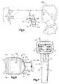
- FIG. 1is a perspective view of a portable data collection device of the present invention with a pivoting member of a viewing assembly in a folded down position;
- FIG. 1Ais a back elevation view of a portion of a housing of the portable data collection device
- FIG. 2is a perspective view of the portable data collection device with the viewing assembly pivoting member in an upright position
- FIG. 3is a sectional view of a portion of a housing of the portable data collection device with the viewing assembly pivoting member in the folded down position;
- FIG. 4is a sectional view of a portion of the housing of the portable data collection device with the viewing assembly pivoting member in the upright position;
- FIG. 5is a view, partly in side elevation and partly in section, of the portable data collection device showing use of the viewing assembly to align the device with a target object;
- FIG. 6is a top plan view of the portable data collection device
- FIG. 7is a front elevation view of the portable data collection device as seen from a plane indicated by the line 7 — 7 in FIG. 6;
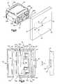
- FIG. 8is a perspective view of a modular portion of an imaging assembly of the portable data collection device of the present invention, the modular portion shown imaging a target dataform on an item;
- FIG. 9is a view of the modular portion of the imaging assembly of FIG. 8 with an upper half of a housing of the modular portion removed;
- FIG. 10is a schematic sectional view of an optic assembly of the modular portion of the imaging assembly of FIG. 8 including a focusing assembly;
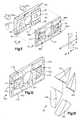
- FIG. 11is an exploded perspective view of an illumination assembly of the modular portion of the imaging assembly of the present invention.
- FIG. 12is a perspective view of a lens array or front panel of the illumination assembly of FIG. 11;
- FIG. 13is an exploded perspective view of a targeting optics of the front panel of FIG. 12;
- FIG. 14is a front elevation view of the front panel of FIG. 12;
- FIG. 15is a back elevation view of the front panel of FIG. 12;
- FIG. 16is a sectional view of the front panel of FIG. 12 as seen from a plane indicated by the line 16 — 16 in FIG. 14;
- FIG. 17is a sectional view of the front panel of FIG. 12 as seen from a plane indicated by the line 17 — 17 in FIG. 14;
- FIG. 18is a sectional view of the front panel of FIG. 12 as seen from a plane indicated by the line 18 — 18 in FIG. 14;
- FIG. 19is an exploded perspective view of an alternate embodiment of an illumination assembly of the modular portion of the imaging assembly of the present invention.
- FIG. 20is a perspective view of a lens array or front panel of the illumination assembly of FIG. 19;
- FIG. 21is an exploded perspective view of a targeting optics of the front panel of FIG. 20;
- FIG. 22is a front elevation view of the front panel of FIG. 20;
- FIG. 23is a back elevation view of the front panel of FIG. 20;
- FIG. 24is a sectional view of the front panel of FIG. 20 as seen from a plane indicated by the line 24 — 24 in FIG. 22;
- FIG. 25is a sectional view of the front panel of FIG. 20 as seen from a plane indicated by the line 25 — 25 in FIG. 22;
- FIG. 25Ais an exploded section view of a portion of the front panel shown in FIG. 25 as seen from a plane indicated by the line 25 A— 25 A in FIG. 22;
- FIG. 26is a sectional view of the front panel of FIG. 20 as seen from a plane indicated by the line 26 — 26 in FIG. 22;
- FIG. 27is a representation of a crosshair illumination pattern generated by the illumination assembly of FIG. 11 superimposed on a target object;
- FIG. 28is a representation of a separation of crosshair illumination patterns of two targeting optics of the illumination assembly of FIG. 11 caused by imaging with the portable data collection device at a distance from a target object significantly different than a best focus position or distance of an optic assembly of the device;
- FIG. 29is a representation of an angular shift of crosshair illumination patterns of two targeting optics of the illumination assembly of FIG. 11 caused by imaging with the portable data collection device tilted such that the front panel is not substantially parallel to a surface of a target object;
- FIG. 30is a representation of a crosshair and half frame illumination pattern generated by a first targeting optics of the illumination assembly of FIG. 19;
- FIG. 31is a representation of a crosshair and half frame illumination pattern generated by a second targeting optics of the illumination assembly of FIG. 19;
- FIG. 32is a representation of a crosshair and full frame illumination pattern generated by the first and second targeting optics of the illumination assembly of FIG. 19;
- FIG. 33is a representation of a matrix dataform and an associated signature block
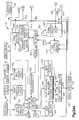
- FIG. 34Ais one portion of a block diagram of selected circuitry of the portable data collection device of the present invention.
- FIG. 34Bis a second portion of a block diagram of selected circuitry of the portable data collection device of the present invention, the second portion matching the first portion shown in FIG. 34A;
- FIG. 35is a flow chart setting forth one operating embodiment of the portable data collection device of the present invention to decode a bar code dataform and capture an image of a target area;
- FIG. 36is a flow chart setting forth a second operating embodiment of the portable data collection device of the present invention to decode a bar code dataform and capture an image of a target area;
- FIG. 37is a flowchart setting forth a third operating embodiment of the portable data collection device of the present invention wherein a captured image frame includes a dataform and a signature block as shown in FIG. 16 and in which decoded dataform data and a portion of the capture image are output;
- FIG. 38is a perspective view of a support fixture for the focusing assembly of the optic assembly of FIG. 10;
- FIG. 39is a sectional view of the focusing assembly support fixture of FIG. 38;
- FIG. 40is front elevation view of a movable wedge shaped optic of the focusing assembly of the optic assembly of FIG. 10;
- FIG. 41is top plan view of the movable wedge shaped optic of FIG. 40 as seen from the plane indicated by the line 41 — 41 in FIG. 40;
- FIG. 42is a schematic sectional view of an optic assembly of the modular portion of the imaging assembly of FIG. 8 including an alternate embodiment of a focusing assembly;
- FIG. 42Ais a side elevation view of a portion the focusing assembly of FIG. 42 as seen from a plane indicated by the line 42 A— 42 A in FIG. 42;
- FIG. 43is a schematic sectional view of an optic assembly of the modular portion of the imaging assembly of FIG. 8 including another alternate embodiment of a focusing assembly;
- FIG. 44Ais one portion of a block diagram of selected circuitry of the portable data collection device of the present invention including the focusing assembly shown in FIG. 43;
- FIG. 44Bis a second portion of a block diagram of selected circuitry of the portable data collection device of the present invention, the second portion matching the first portion shown in FIG. 44 A.
- the data collection device 10includes a housing 12 defining an interior region.
- the housing 12includes a gripping portion 14 sized to be grasped in the hand of an operator and an angled snout 16 extending from the gripping portion.
- the snout 16includes an opening through which a portion of a two dimensional (2D) photosensor array imaging assembly 18 extends.
- the imaging assembly 18includes a modular portion 20 and a control and decoder board 22 electrically coupled to the electronic circuitry in the modular portion.
- the control and decoder board 22is supported within the gripping portion 14 of the housing 12 .
- a power source 24such as a rechargeable battery for supplying operating power to the portable data collection device 10 .
- a dataform reading trigger switch or actuator 26extends through an opening in the gripping portion 14 . Also extending through an opening in the gripping portion 14 is an imaging push button trigger switch or actuator 28 .
- the dataform reading trigger 26is positioned to be depressed by an index finger of the operator while the gripping portion 14 of the housing 12 is held in the operator's hand.
- the imaging trigger 28is positioned to be depressed by a thumb of an operator while the gripping portion 14 of the housing 12 is held in the operator's hand.
- a slider 29moveable along a path of travel defined by a slotted opening 29 a in the gripping portion 14 .
- moving the slider 29causes a best focus position or distance of an optic assembly 43 of the imaging assembly 18 to change thereby allowing the operator to change a focusing range of the dataform reader 10 .
- the slider 29is positioned on the housing snout 16 to permit operation by the operator's thumb. Moving the slider 29 to an end 29 b (FIG. 1A) of the slotted opening 29 a causes the optic assembly 43 to have a best focus distance at approximately 5.5 inches (140 mm.) in front of an outwardly facing surface 90 of a forwardmost lens of the optic assembly 43 .
- the gripping portion 14also includes two small openings through which a distal portion of a red light emitting diode (LED) indicator 30 and a distal portion of a green LED indicator 32 extend.
- the housing 12includes an opening exposing a portion of a microphone 34 mounted in the housing interior region and another opening through which a radio antenna 36 extends. The interior region of the housing 12 supports the imaging assembly 18 and other electronic circuitry to be described below.
- the modular portionincludes a housing 40 which supports an illumination assembly 42 and a board camera assembly 38 .
- the housing 40includes an upper portion 39 a and a lower portion 39 b which advantageously are identically shaped and positioned symmetrically about a part line 41 .
- the board camera assembly 38includes the optic assembly 43 which focuses an image of a target area 44 onto a photosensor array 48 .
- the target area 44is defined by a field of view of the board camera assembly 38 .
- the target area 44will generally include a target object 45 such as a one or two dimensional bar code dataform or a matrix dataform to be decoded.
- the illumination assembly 42includes four illumination optic portions 88 a , 88 b , 88 c , 88 d each of which projects an even intensity distribution of illumination across the target area 44 .
- FIG. 9is a top view of the modular portion 20 with the upper portion 39 a of the housing 40 removed.
- the board camera assembly 38includes a rear printed circuit board 52 and a front printed circuit board 54 , both of which are secured in the housing 40 in slots 56 a , 56 b , 56 c , 56 d .
- a two dimensional photosensor array 48is positioned on a support 49 (FIG. 10) affixed to a front surface 54 a of the front printed circuit board 54 .
- the photosensor array 48receives reflected illumination from the target area 44 focused through an optic assembly 43 .
- the support 49surrounds the photosensor array 48 and holds a thin piece of quartz 50 in spaced apart, parallel relationship with wht photosensor array 48 .
- the quartz piece 50has a thickness of 0.6 mm. and is spaced 1.310 mm. from the photosensor array 48 .
- the quartz piece 50has an index of refraction of 1.5443.
- a shroud 58positions the optic assembly 43 with respect to the photosensor array 48 and shrouds ambient illumination from the array.
- the illumination assembly 42includes a printed circuit board 60 , a lens array 62 and two targeting LEDs 64 a , 64 b .
- the lens array 62functions as the outer or front panel of the modular portion 20 .
- the term “front panel”will be used interchangeably with the term “lens array” throughout.
- a plurality of exposure LEDs 66are disposed on the front surface of the printed circuit board 60 to direct illumination through the front panel 62 towards the target area 44 .
- the circuit board 60 and the front panel 62are secured in slots 56 e , 56 f , 56 g , 56 h in the upper and lower housing portion 39 a , 39 b . Securing the board camera assembly 38 and the illumination assembly 42 in the same housing 40 assures that illumination is properly directed onto the target area 44 .
- FIG. 10shows a cross section of the camera assembly 38 with the optic assembly 43 focusing an image of the target area 44 including an image of the target object 45 onto the photosensor array 48 .
- the performance of the portable data collection device 10is enhanced by the optic assembly 43 including a focusing assembly 800 which provides the board camera assembly 38 with an extended, variable working range.
- the focusing assembly 800is operable to vary a best focus position or distance S 2 (FIG. 10) of the optic assembly 43 .
- the best focus position S 2is a distance from an outermost optic surface 90 of a forwardmost lens 43 a of the optic assembly 43 to the target object 45 at which the best or clearest image of the target object is focused on the photosensor array 48 .
- the sharpness of the focused imagegradually degrades as the target object 45 is moved from the best focus position S 2 towards a near field cut off distance S 1 . If the target object 45 is a dataform, moving the target object 45 closer than the near field cut off distance S 1 would result in an image projected onto the photosensor array 48 that is undecodable. Similarly, the image sharpness gradually degrades as the target object 45 is moved from the best focus position S 2 towards a far field cut off distance S 3 . Assuming that the target object 45 is a dataform, moving the target object 45 further away than the far field cut off distance S 1 would result in an image projected onto the photosensor array 48 that is undecodable.
- the focusing module 800includes a focusing optic 810 comprising two wedge shaped lens 820 , 830 which are congruent in shape and supported in a lens support fixture 840 (seen in FIGS. 38 and 39 ).
- a focusing optic 810comprising two wedge shaped lens 820 , 830 which are congruent in shape and supported in a lens support fixture 840 (seen in FIGS. 38 and 39 ).
- the lens 820 , 830when viewed from above, define congruent triangles.
- the angles labeled “a” in the lens 820 , 830are both substantially 90 degree angles and the acute angle labeled “b” in lens 820 is substantially equal to the acute angle labeled “b” in lens 830 .
- the lens 820 , 830are supported by the fixture 840 such that the flat, inclined surfaces 822 , 832 of lens 820 , 830 are parallel and adjacent.
- outwardly facing flat surfaces 824 , 834are substantially parallel.
- the focusing optic 810is positioned such that it is substantially perpendicular to a central ray c (FIG. 10) of reflected light from the target area 44 which passes through lens 43 a , 43 b , 43 c , 43 d , 43 e of the optic assembly 43 .
- the lens 820 , 830are preferably fabricated from type BK7 glass having a refractive index of 1.5168. Type BK7 glass is available from Schott Glass Technologies, Inc. of Duryea, Pa.
- the focusing module 800is configured such that an effective thickness t FIG. 10) of the focusing optic 810 through which the reflected light passes may be changed by the operator of the portable data collection device 10 to vary the best focus position S 2 of the optic assembly 43 .
- the near field cut off distance S 1 and the far field cut off distance S 2will also be changed as follows:
- Thickness Best Focus Distance Near Field Cutoff Far Field Cutoff t S2 S1 S31.0 mm. 140 mm. (5.5 in.) 65 mm. (2.5 in.) 290 mm. (11.5 in.) 1.726 mm. 305 mm. (12.0 in.) 90 mm. (3.5 in.) 600 mm. (23.5 in.) 2.136 mm. 915 mm. (36.0 in.) 150 mm. (6.0 in.) Infinity
- MIN S 2The minimum value of S 2 (5.5 in. or 140 mm.) will be referred to as MIN S 2 .
- Suitable dimensions for the two lens 820 , 830 comprising the focusing optic 810are as follows:
- the distance labeled D 1corresponds to a distance between an optic surface 110 of the rearwardmost lens 43 e and the forward facing surface 824 of the lens 820 .
- a suitable distance D 1is 3.1209 mm.
- the distance labeled D 2corresponds to a distance between the rearward facing surface 834 of the lens 830 and the photosensor array 48 .
- a suitable distance D 2is 4.4000 mm.
- the thickness t of the focusing optic 810is varied by moving or sliding the lens 820 with respect to the lens 820 .
- the moveable lens 820includes a pair of projecting flanges 825 , 826 extending from top and bottom surfaces 827 , 828 of the lens 820 .
- the projecting flanges 825 , 827slidingly engage respective slots 842 , 844 of spaced apart horizontal plates 846 , 848 of the support fixture 840 .
- the slots 842 , 844function to guide the projecting flanges 825 , 827 and, therefore, the moveable lens 820 along a path of travel labeled T in FIG. 39 .
- a drive means 850is provided to move the moveable lens 820 along the path of travel T.
- the drive means 850includes a flexible belt 852 having one end 854 attached to a base surface 829 of the lens 820 .
- An opposite end 856 of the belt 852is attached to the slider 29 .
- a portion 29 d of the slider 29extends through the slotted opening 29 a in an operator facing back side of the snout 14 of the housing 12 .
- the slider 29is slidably confined between a pair of parallel ledges 29 e , 29 f (which can be seen in dashed line in FIG. 1 A and one of which can be seen in FIG. 10) which extend outwardly from the inner surface 16 a of the housing snout 16 .
- the ledges 29 e , 29 fhave peripheral lips 29 g to further confine the slider 29 .
- the belt 852moves in the same direction and the lens 820 correspondingly moves.
- the belt 852is supported by guides 858 , 860 extending from an inner surface of the housing snout 16 .
- the belt 852extends through a guide 862 defining an opening in the modular housing 20 and another guide 864 defining an opening in the shroud 58 .
- the belt 852further extends through a guide 866 in a vertical side plate 868 of the fixture 840 .
- the fixtureincludes the vertical side plate 868 and another vertical side plate 870 which function to maintain the proper spaced relation between the horizontal plates 846 , 848 .
- the fixture 840is secured to the front side 54 a of circuit board 54 by four screws 872 extending through openings in flanges 874 and through the circuit board 54 .
- the flanges 874extend from the horizontal plates 846 , 848 .
- the belt 852is flexible enough the conform to the curves defined by the guides 858 , 860 but is stiff enough to move the moveable lens 820 along its path of travel T when the slider 29 is moved along the slotted opening 29 a .
- lens 820moves along its path of travel T guided by the engagement of the projecting flanges 825 , 827 and the slots 842 , 844 of spaced apart horizontal plates 846 , 848 .
- the moveable lens 820moves the moveable optic contact surface 822 slides across the stationary optic contact surface 832 thereby varying the thickness t of focusing optic 810 , that is, varying the total distance the reflected light from the target area 44 must traverse before reaching the photosensor array 48 .
- the stationary lens 830can be thought of as a compensation lens because it causes the focusing optic 810 to have a shape of a plate of glass with two parallel faces oriented such that the faces are normal or perpendicular to the incident reflected light no matter what the position of the moveable lens 820 .
- Different positions of the moveable lens 820are shown in FIG. 10 .
- a position of the lens 820 at one end of its path of travel Tis shown. This position corresponds to a minimum thickness t of the focusing optic 810 .
- an intermediate position of the lens 820is shown corresponding to a medium thickness t of the focusing optic 810 .
- a position of the lens 820 at an opposite end of its path of travel Tis shown. This position corresponds to a maximum thickness t of the focusing optic 810 .
- the moveable lens 820is at the position which results in a minimum thickness t of the focusing optic 810 .
- the moveable lens 820is at the position labeled 820 b which results in a maximum thickness t of the focusing optic 810 .
- the resulatant focusing optic 810is equivalent to a glass plate with parallel sides and variable thickness. Since the index of refraction of the focusing optic 810 (1.5168) is greater than the index of refraction of air, inserting the optic 810 between the innermost lens 43 e of the optic assembly 43 and the photosensor array 48 will change the best focus distance S 2 . As the thickness of the focusing optic 810 increases, the best focus distance S 2 also increases. Thus, imprinted on the housing snout 16 adjacent the end 29 b of the opening 29 a is the letter “N” indicating to the operator that moving the slider 29 toward the end 29 b will cause the optic assembly 43 reduce its best focus distance S 2 .
- the opposite end 29 chas a letter “F” imprinted near it to indicate that moving the slider toward the end 29 c will increase the best focus distance S 2 . Since the focusing optic 810 is essentially a glass plate with parallel sides, the reflected light passing through the optic 810 is not subject to image shift or tilt.
- the best focus position MIN S 2is at 140 mm. (5.5 in.) from the outward facing optic surface 90 of the lens 43 a .
- the field of view or target area 44 of the optic assembly 43is generally rectangular in shape and having dimensions of approximately 82 mm. (3.2 in.) long by 62 mm. (2.4 in.) high.
- the target area of the optic assembly 43is approximately 127 mm. (5 inches) long by 95 mm. (3.75 inches) high.
- the optic assembly 43is capable of decoding a bar code dataform with narrow width bars (e.g., a bar code dataform with a minimum bar width of 0.015 in. (0.381 mm.) at the near field distance S 1 ).
- the preferred optic assembly 43includes the five lens 43 a , 43 b , 43 c , 43 d , 43 e and a metal disk 98 having a pin hole aperture 98 a which, as shown, includes eleven optic surfaces labeled 90 - 110 .
- the rear most optic surface 110 of lens 43 eis positioned 10.2 mm. to the front of the photosensor array 48 , that is, the distance labeled DT in FIG. 10 is 10.2 mm.
- the optic prescriptions for each of the optic surfacesare as follows:
- the distance between successive optical surfaces 90 - 110is as follows:
- Such an optic assemblyis available from Marshall Electronics, Inc. of Culver City, Calif.
- the illumination assembly 42must provide adequate illumination of the target area 44 during the exposure period so that enough reflected light is absorbed by the photosensor array 48 to generate a suitably bright image.
- the exposure periodis normally limited to 0.01 seconds or less to minimize the smear effect of an operator's hand jittering during a dataform reading session. Therefore, the illumination assembly 42 must provide adequate illumination to accommodate the large F# and short exposure time.
- the minimum required object field illumination for this inventionis 106 lux at the far field cut off distance S 3 .
- the printed circuit board assembly 60includes a plurality of surface mount exposure illumination LEDs 66 .
- An acrylic or polycarbonate lens array 62is positioned between the printed circuit board assembly 60 and the target area 44 for directing the illumination from the exposure LEDs 66 towards the target area 44 .
- the lens array 62is a unitary structure fabricated from the material PMMA (polymethyl methacrylate).
- PMMApolymethyl methacrylate
- the printed circuit board assembly 60includes printed conductors and a power lead 112 operative for supplying power to the illumination LEDs 66 .
- a suitable surface mount illumination LEDis produced by the MarkTech Corporation of Latham, N.Y., as Part No. MTSM735K-UR or MTSM745KA-UR.
- Each illumination LED 66provides illuminosity of 285 milli candela (mcd) over an angular illumination field of about 68 degrees.
- the small footprint of each illumination LED 66enables four LEDs to be placed in a row measuring less than 14 mm.
- the printed circuit board assembly 60includes four banks of four illumination LEDs 66 totaling sixteen illumination LEDs providing 4560 mcd of uniform illumination over the target area 44 .
- the lens array 62includes four illumination optic portions 88 a , 88 b , 88 c , 88 d each of which are aligned with a corresponding bank of illumination LEDs 66 .
- the illumination optic portions 88 a , 88 b , 88 c , 88 ddirect a 68 degree angular illumination field from each illumination LED 66 into a uniform field having an angular field of view which substantially corresponds to the angular field of view of the optic assembly 43 which defines the target area 44 (shown in FIGS. 8 and 9 ).
- each optic portionincludes four vertically oriented cylindrical entry surfaces 116 , one positioned in front of each LED 66 and a horizontally oriented cylindrical exit surface 118 positioned in front of each bank of LEDs 66 .
- the vertically oriented cylindrical entry surfaces 116define the horizontal field of illumination and the horizontally oriented cylinders 118 define the vertical field of illumination. This arrangement provides an even illumination intensity distribution across the target area 44 .
- the 4560 mcd of illumination provided by the illumination LEDs 66will provide an illumination intensity in excess of 106 lux at a distance of 8.5 inches from the outermost optic surface 90 of the optic assembly lens 43 a.
- a central opening 67 in the printed circuit board assembly 60provides an opening for the shroud 58 to extend through.
- the vertically oriented entry surfaces 716have a radius of curvature of 2.50 mm. and a height I (FIG. 35) of 4.00 mm while the horizontally oriented exit surfaces 718 have a radius of curvature of 3.00 mm. and a width J (FIG. 36) of 13.75 mm.
- suitable dimensions for the lens array 702are as follows:
- the illumination assembly 42also includes a targeting arrangement or assembly 64 to aid in aiming the device 10 at the target object 45 .
- the targeting assemblyincludes the targeting LED illuminators 64 a , 64 b , which, when energized, project illumination through apertures 68 , 70 in the printed circuit board 60 and into first and second targeting optics 72 , 74 respectively of the lens array 62 .
- the first and second targeting optics 72 , 74are mirror images of each other and are identical in configuration. Each targeting optic generates a crosshair pattern of illumination CR 1 , CR 2 (seen in FIG.
- the crosshairs CR 1 , CR 2will coincide or overlap producing a single rectangular crossing or crosshair pattern of illumination CR (FIGS. 11 and 27 ).
- the rectangular illumination pattern CRwill have a height h (18 mm.) and a width w (18 mm.) (FIG. 11 ).
- the rectangular illumination pattern CRwill not be a perfect intersecting line crosshair but rather will be characterized by an illumination intensity distribution or pattern having some visible “thickness” t (FIG. 11) but will nonetheless be suitable for aiming the device 10 .
- the first and second targeting optics 72 , 74which are identical in configuration, are shown in cross section in FIGS. 17 and 18.
- the first targeting optics 72comprises a lens with an aspherical light entry optic surface 726 and a segmented cylindrical light exit optic surface 728 .
- the second targeting optics 74comprises a lens with an aspherical light entry optic surface 730 , similar to the aspherical light entry optic surface 726 , and a segmented cylindrical light exit optic surface 732 , similar to the segmented cylindrical light exit optic surface 728 .
- the aspherical entry surfaces 726 , 730each have a diameter of 8 mm., a radius of curvature of 2.890 mm. and a conic constant of ⁇ 2.534.
- the segmented cylindrical light exit surfaces 728 , 732each have an 8.0 mm. by 8.0 mm. square shaped outer perimeter.
- the segmented cylindrical surface 728is comprised of four triangular shaped sections 740 , 742 , 744 , 746 (FIG.
- segmented cylindrical surface 732is divided into four triangular shaped sections 750 , 752 , 754 , 756 , wherein the optic surfaces of sections 740 and 750 are identical, the optic surfaces of sections 742 and 752 are identical, the optic surfaces of sections 744 and 754 are identical and the optic surfaces of sections 746 and 756 are identical.
- Upper and lower triangular sections 740 , 744comprise vertically oriented cylindrical light exit optic surfaces.
- Left and right triangular sections 742 , 746comprise horizontally oriented cylindrical light exit optic surfaces.
- upper and lower triangular sections 750 , 754comprise vertically oriented cylindrical light exit optic surfaces, while left and right triangular sections 752 , 756 comprise horizontally oriented cylindrical light exit optic surfaces.
- the vertically oriented cylindrical optic surfaces 740 , 744 , 750 , 754have a radius of curvature of 25.00 mm.
- the horizontally oriented cylindrical optic surfaceshave a radius of curvature of 25.00 mm.
- the horizontally and vertically oriented cylindrical optic surfaces 742 , 746 , 740 , 744are tipped at an angle c with respect to a longitudinal axis L—L though the lens array 62 and, therefore, is also tipped at an angle c with respect to the target area 44 .
- the tip angle c of the horizontally oriented cylindrical optic surfaces 742 , 746shifts the horizontal position of the illumination rectangle or targeting crosshair CR 1 (seen in FIG.
- a suitable tip angle of cis 9.85 degrees.
- the horizontally and vertically oriented cylindrical optic surfaces 752 , 756 , 750 , 754are also tipped at an angle c which is preferably 9.85 degrees with respect to a longitudinal axis L—L though the lens array 62 .
- the direction of tilt of the segmented cylindrical light exit surfaces 728 , 732are the same in magnitude but opposite in a direction of tilt, that is, the light exit surface 728 of the first targeting optics 72 slants downwardly to the left toward the front side 719 in FIG. 17, while the light exit surface 732 of the second targeting optics 74 slants downwardly to the right toward the front side 719 in FIG. 17 .
- FIG. 13which shows the segmented cylindrical light exit surface 732 as being comprised of four individual exploded “pieces” is only a representation to provide additional clarity as to the shape and tilt of the four light exiting surfaces 750 , 752 , 754 , 756 .
- the lens array 62is fabricated as a single piece and the targeting optics 72 , 74 and illumination optics 116 , 118 are formed in the single piece. The lens optics are not fabricated by “piecing” together individual optics. The same is true with respect to the optic “pieces” represented in FIG. 21 of the alternate embodiment of the illumination assembly 42 shown in FIGS. 19-26 to be discussed below.
- the minimum best focus distance MIN S 2is 140 mm. (5.5 inches). If the device 10 is oriented such that the lens array 72 is substantially parallel to a surface of the target object 45 (a dataform to be imaged and decoded) and positioned at the minimum best focus distance MIN S 2 from the target object 45 , then the targeting crosshairs CR 1 and CR 2 will coincide and generate the single targeting crosshair CR as shown in FIGS. 11 and 27 having an approximate height h of 18 mm . (0.7 in.) and an approximate width w of 18 mm . (0.7 in.) which corresponds to the target area 44 height of 62 mm. (2.4 in.) and a width of 82 mm. (3.2 in.) at the minimum best focus position MIN S 2 of 140 mm. (5.5 inches) in front of the optic surface 90 .
- the targeting crosshairs CR 1 and CR 2will separate horizontally as shown in FIG. 28 thereby informing the operator that the distance of the device 10 from the target object 45 is not correct for best imaging or imaging and decoding.
- the operatorwill adjust the focusing optic 810 using the slider 29 appropriately to compensate for the distance between the target object 35 and the optic assembly 43 .
- the operatorwould use his or her thumb to move the slider 29 to the “F” marked end 29 c of the slotted opening 29 a so as to increase the best focus distance S 2 from its minimum value (140 mm. or 5.5 in.) to its maximum value (915 mm. or 36.0 in.).
- the preferred mode of operationwould be to have the slider 29 at the “N” marked end 29 b of the slotted opening 29 a and adjust the device's distance from the target object 45 such that the CR 1 and CR 2 crosshairs overlap.
- the target object distancewill be 140 mm. (5.5 in.) and corresponding to the optic assembly 43 minimum best focus distance MIN S 2 140 mm. (5.5 in.).
- the lens array 702is not substantially parallel to a surface of the target object 45 , that is, the device 10 is tilted forward or backward from a position where a front surface 719 (FIGS. 12 and 17) of the lens array or front panel 72 is parallel to the target object surface, the vertical portions of the illumination patterns of CR 1 and CR 2 will be angularly shifted or displaced as shown in FIG. 49, the greater the angle of tilt of the device 10 , the greater will be the angular shifting of the vertical portions of the illumination patterns CR 1 , CR 2 .
- the portable data collection device 10also includes a viewing assembly 600 .
- the viewing assembly 600includes a pivoting member 602 which pivots between a folded down position (FIGS. 1 and 3) and an upright position (FIGS. 2 and 4 ).
- the pivoting member 602includes a rectangular opening 604 .
- the opening 604is approximately 32 mm. in the horizontal direction, labeled 606 in FIG. 2, and is approximately 24 mm. in the vertical direction, labeled 608 in FIG. 2 .
- the horizontal and vertical dimensions 606 , 608 of the opening 604are chosen such that an angle of divergence or field of view of an operator 605 looking through the opening 604 at a distance of approximately 56 mm, labeled ED in FIG.
- the ratio of the horizontal dimension 606 to the vertical dimension 609is chosen to correspond to the ratio of the horizontal dimension to the vertical dimension of the matrix of photosensors comprising the 2D photosensor array 48 .
- the pivoting member 602when in an upright position, the pivoting member 602 is in a line of vision of the operator 605 .
- a viewing area 610 through the aperture 604substantially corresponds to the target area 44 of the imaging assembly 18 .
- the pivoting member 602when in the folded down position, is received in a well or recessed area 608 defined by an upper surface of the housing snout 16 .
- an upper surface 612 (FIG. 3) of the pivoting member 602is substantially flush with the snout upper surface.
- the snout upper surface 610includes a recessed portion 614 (FIGS. 1 and 2) sized to permit an operator's finger tip to slip under a front lip 616 of the pivoting member 602 to permit the member to be popped up to the upright position from the folded down position.
- the pivoting member front lip 616 member 602fits under a slightly extending upper edge 617 of the snout upper surface to hold the pivoting member with a slight interference fit in the folded down position.
- the pivoting member 602pivots on a pair of cylindrical portions 618 which extend from sides of the pivoting member near its bottom edge.
- the cylindrical portions 618rotatably fit within corresponding cylindrical recesses in the snout 16 .
- an arcuate biasing spring 620positioned in a recessed portion 622 of the snout 16 .
- the recessed portion 622is shaped to confine the spring 620 with edge portions of the snout defining the recessed portion.
- the spring 620has a humped middle portion which biases the pivoting member 602 to either the upright position or the folded down position.
- the photosensor array 48is part of the board camera assembly 38 commercially available from such vendors as Sharp or Sony of Japan. Referring to FIGS. 17A and 17B, the camera assembly, when activated, generates a composite video signal 262 .
- the board camera assembly 38also includes a clock generator 256 , synchronization signal circuitry 258 and analog signal processing circuitry 260 for reading illumination intensity values out of each photosensor of the photosensor array 48 and generating the composite video signal 262 .
- the intensity of light incident on individual pixels or photosensors of the photosensor array 48varies somewhat uniformly from very bright (whitest areas of the image) to very dark (darkest areas of the image).
- the preferred 2D photosensor array 48comprises an interlaced 752 by 582 matrix array of photodiode photosensors or image pixels (for a total of 437,664 pixels).
- the clock generator 256coupled to a crystal oscillator and generates asynchronous clocking signals to read out charges accumulating on individual photosensors over an exposure period.
- the charges on the photosensorsare read out through CCD elements adjacent the photosensor array photosensors.
- the chargesare converted to a voltage signal 250 wherein temporal portions of the voltage signal represent the changes accumulated on each photosensor.
- One CCD elementis provided for reading out the charges on two photosensors thus two read outs of the photosensor array comprise one full image frame, the frame being comprised of two interlaced fields.
- the camera assembly 38generates the composite analog video signal 262 (FIG. 17A) corresponding to consecutive fields of the image incident on the photosensor array 48 .
- the video signal 262is termed “composite” because it includes synchronization signals generated by the synchronization signal circuitry 258 which correlate portions of the video signal to particular photosensors, interspersed among image signal portions wherein the signal magnitude represents charges on individual photosensors read out from a given row of the photosensor array 48 .
- the board camera assembly 38also includes gain control circuitry 252 for controlling amplification of the image signal 253 and exposure period control circuitry 254 for controlling a duration of an exposure period of the pixels. Both the exposure period control circuitry 254 and the gain control circuitry 252 are controlled by fuzzy logic exposure parameter control circuitry discussed with reference to FIG. 34 A.
- the synchronization signals 268 generated by synchronization signal circuitry 258 , the clock signal 270 , generated by the clock generator 256 , and the composite video signal 253are output to signal processing circuitry 264 on the control and decoder board 22 . Because the signal processing circuitry is configured to receive a composite video signal, it should be appreciated that selection of the board camera assembly 38 and its accompanying components for generating the composite video signal are not critical to the present invention.
- the video signal 262is input to the signal processing circuitry 264 along with clocking signals 268 and synchronization signals 270 .
- the signal processing circuitry 264includes synchronization extractor circuitry which receives the clocking signals 268 and the synchronization signals 270 and generates signals which are coupled to analog to digital converter circuitry (A/D converter circuitry) 272 causing the A/D converter circuitry to periodically digitize the video signal 262 .
- the A/D converter circuitry 272includes an A/D converter generating an 8 bit value representing the illumination incident on a pixel of the array.
- Direct memory access (DMA) control circuitry 275receives the synchronization signals 270 and clock signals 268 and generates address signals 276 a coupled to the frame buffer memory 274 to indicate a storage location for each value generated by the A/D converter circuitry 272 .
- DMADirect memory access
- Data signals 276 representing the values generated by the A/D converter circuitry 272are coupled to the frame buffer memory 274 .
- Control and selection circuitry 284 mounted on the control and decoder board 22 and coupled to the frame buffer memory 274receives successive image frames temporarily stored in the frame buffer memory 274 .
- Also coupled to the control and selection circuitry 284are the dataform read trigger circuit 26 a which, in turn, is coupled to the dataform reading trigger 26 and an image capture trigger circuit 28 a which, in turn, is coupled to the imaging trigger 28 .
- the dataform read trigger circuit 26 aWhen an operator institutes a dataform reading session (dataform reading mode) by depressing the dataform reading trigger 26 , the dataform read trigger circuit 26 a sends a signal to the control and selection circuitry 284 causing the control and selection circuitry to couple a captured frame from the frame buffer memory 274 to image processing and decoder circuitry 290 .
- the image processing and decoding circuitry 290includes a decoder 292 for decoding 1D and 2D dataforms in the target area 44 .
- the image processing and decoder circuitry 290operates on the stored frame of image data to extract dataform cell data (determine the black or white value of each cell of the dataform) and decode the cell data.
- Cell extractionis done in accordance with U.S. patent application Ser. No. 08/543,122 entitled, “Sub Pixel Dataform Reader With Dynamic Noise Margins”, filed Oct. 13, 1995 now issued as U.S. Pat. No. 5,979,763 on Nov. 9, 999, and assigned to the assignee of the present invention.
- the contents of application Ser. No. 08/543,122are hereby incorporated by reference.
- Decoding of the cell datais accomplished by known decoding methods for each particular dataform format.
- image compression circuitry 294Also coupled to the control and selection circuitry 284 is image compression circuitry 294 and serial output circuitry 296 .
- the control and selection circuitry 284routes data 298 representing a decoded dataform data directly from the decoding circuitry 292 to the serial output circuitry 296 .
- the decoded dataform data 298is not compressed prior to output to the serial output circuitry 296 .
- There is a possibility of error in the compression and subsequent decompression process and losing even a portion of a decoded dataform datamay result in adverse consequences such as subsequent errors in updating inventory, determining the status or tracking an item, etc.
- the decoded dataform data 298is not compressed.
- the image capture trigger circuit 28 aWhen an operator institutes an imaging session (imaging mode) by depressing the imaging trigger 28 , the image capture trigger circuit 28 a sends a signal to the control and selection circuitry 284 causing the selection circuitry to couple a captured frame from the frame buffer memory 274 to image compression circuitry 294 to be compressed before being output to the serial output circuitry 296 or directly to the serial output circuitry 296 without being compressed.
- control and selection circuitry 284will be programmed to route the data representing a captured image frame to the image compression circuitry 294 because the occurrence of one or more errors in the data representing an image is normally not a significant problem. That is, an image of an item in the target area 44 will still be recognizable and useful to supervisory personnel viewing the image reconstructed from the captured image frame data even if there is some slight distortion of the image.
- compressed image data 300is routed to the serial output circuitry 296 . If, however, a high resolution image is needed, the control and selection circuitry 284 may be appropriately programmed to route the data representing the captured frame directly to the serial output circuitry 296 .
- the image compression circuitry 294utilizes an image compression algorithm to reduce the size of a set of digital image data.
- One such algorithmis the 2D wavelet transform compression algorithm as described in “A 64 Kb/s Video Code Using the 2D Wavelet Transforms” by A. S. Lewis and G. Knowles, published in IEEE Computer Society Press, Order No. 2202.
- the HARC Wavelet Transform System utilizing such technologyis available from Houston Advance Research Center in Houston, Tex. and is capable of compressing photographic data with an image compression ratio of up to 400:1.
- the control and decoder board 22also includes a voice capture module 304 for capturing and digitizing an operator's verbal message and voice compression circuitry 306 for compressing the captured verbal message.
- the voice capture module 304is coupled to the microphone 34 and is operable by the control and selection circuitry 284 to capture and digitize audio input.
- the voice compression circuitry 306compresses a digitized voice signal.
- Data 308 representing the compressed digitized voice signalis coupled to the serial output circuitry 296 .
- the control and selection circuitry 284monitors the image capture trigger switch 28 . If the operator depresses the trigger 28 during the predetermined period, the voice capture module 304 and voice compression circuitry 306 are activated for verbal input. As long as the operator keeps the trigger depressed, the voice capture module 304 and voice compression circuitry 306 will remain activated so that the operator can speak into the microphone 34 and provide information concerning an item whose image was captured or whose dataform was read which will be transmitted and/or stored with the corresponding image or decoded dataform.
- the voice capture module 304will be used subsequent to an imaging session where the operator wants to communicate to supervisory personnel reviewing the captured image some additional information concerning the imaged item such as the item's location, a short description of the problem with the item, etc.
- the voice compression circuitry 306utilizes one of a number voice compression algorithms well known to those skilled in the art.
- Decoded dataform data 298 , compressed image data 300 and compressed digitized voice data 308are routed to the serial output circuitry 296 which assembles output data 310 for serial output through a serial output port 312 .
- the serial output port 312is coupled to an input port of a radio module 314 mounted on the control and decoder board 22 (shown schematically in FIG. 5 ).
- the radio module 314modulates and transmits the output data 310 to a remote device (not shown) where the transmitted data is demodulated.
- the demodulated output datamay be used to update inventory, and/or accounting records, update production control expediting or product tracking files, permit supervisory corrective action to remove/repair damaged items, etc.
- the control and decoder board 22further includes exposure parameters control circuitry 316 which outputs control signals 318 , 320 to the exposure period control circuitry 254 and the gain control circuitry 252 of the camera assembly 38 and a signal 322 embodying an appropriate set of reference voltages for operating the A/D converter 272 .
- the exposure parameters control circuitry 316includes fuzzy logic circuitry 324 which analyzes captured frames of data accessed from the frame buffer memory 274 .
- the fuzzy logic circuitry 324analyzes a captured frame to determines if the current exposure period of the 2D photosensor array 48 , the current amplification of the video signal 250 by the gain control circuitry 252 and the reference voltages used by the A/D converter circuitry 272 are resulting in an “acceptable” captured image frame.
- control signal 318is changed to adjust the exposure period of the 2D photosensor array 48 and/or the control signal 320 is changed to adjust the amplification of the video signal 250 and/or the signal 322 is changed to adjust the operation of the A/D converter circuitry 272 .
- another captured frameis analyzed by the fuzzy logic circuitry 324 and, if necessary, further adjustments are made in an iterative fashion until the camera assembly 32 produces an “acceptable” captured image.
- a suitable exposure parameter control circuit including fuzzy logic control circuitryis disclosed in U.S. Pat. No. 5,702,059, previously referenced
- the power source 24is coupled to the control and decoder board 22 to provide operating power to the microprocessor 266 and other circuitry mounted on the board and the radio module 314 .
- Power circuitry 326 under the control of the microprocessor 266is coupled through a lead 328 to the illumination assembly 42 and the camera assembly 38 to supply power to these components of the imaging assembly 18 .
- the flow chart shown in FIG. 35illustrates the operation of the imaging assembly 18 in the dataform decoding mode and a first operating embodiment of the imaging mode.
- a single frame of the image in the target area 44is captured, compressed and output when the operator depressed the imaging trigger 28 .
- the flow chart shown in FIG. 36illustrates the operation of the imaging assembly 18 in the dataform decoding mode and a second operating embodiment of the imaging mode. In the second operating embodiment of the imaging mode, successive frames of the image in the target area 44 are captured, compressed and output as long as the operator has the imaging trigger 28 depressed.
- the imaging assemblyis actuated in the dataform reading mode and to decode a dataform within the image area and to capture the digital image dataform selected image area such as a signature box.
- the imaging system 18determines a position of the dataform in the target area and then determines the position of the signature box.
- the digital image data corresponding to the portion of the image area including the signature boxis output in either compressed or noncompressed form through the serial output port 312 .
- the imaging modeis advantageously employed when the operator using the portable data collection device 10 notices the item 46 is damaged, out of place, incomplete, etc.
- the imaging mode of the imaging assembly 18is used to capture an image of the item 46 and, using the radio module 314 , transmit the captured image to a remote device accessible by supervisory personnel so that the problem may be ascertained by supervisory personnel and appropriate corrective action taken, e.g., deletion of item from inventory records, issuance of order to remove item from storage location and return to production facility or vendor for rework/repair, moving item to proper location, filing insurance claim, etc.
- the imaging assembly 18waits for a signal representing either actuation of the imaging trigger 28 or the dataform reading trigger 26 to commence either an image capture session or a dataform reading session.
- the signalmay be generated by the image capture trigger circuit 28 a , the dataform reading trigger circuit 26 a or by a signal generated by customer specific application software.
- the imaging assembly 18is activated and a frame of image data captured and stored in the frame buffer memory 274 .
- the fuzzy logic circuitry 324determines if the captured image frame is acceptable, that is, the image is within predetermined acceptable ranges for brightness and the magnitude of charges on the photosensors of the 2D photosensor array 48 . If the fuzzy logic circuitry 324 determines the captured frame is not acceptable, one or more of the operating parameters of the camera assembly 38 and the A/D converter circuitry 272 are modified as shown at step 406 . The loop represented by steps 402 , 404 , 406 are repeated until the captured frame is determined to be acceptable.
- the captured frameis coupled to the image processing and decoder circuitry 290 for attempted decoded of the dataform represented in the captured frame.
- the decoding circuitry 292attempts to decode the dataform represented in the captured frame.
- a determinationis made if the decoding was successful.
- the extracted decoded datais output to the serial output circuitry 296 and at step 416 , the green LED indicator 32 is energized for a predetermined time to signal the operator that the dataform 45 in the target area 44 has been successfully read. Subsequently, the imaging assembly 18 is turned off.
- the selection circuitryat energizes the red LED indicator 30 for a predetermined time to signal to the operator that the decoding was unsuccessful and that he or she should continue to point the device 10 at the dataform 45 in the target area 44 .
- the processreturns to step 402 where another image frame is capture and the remaining steps are repeated.
- the control and selection circuitry 284determines that the activation signal is from the imaging trigger 28 , the captured frame is routed to image compression circuitry 294 to compress the data in the captured frame, shown at step 418 .
- the compressed image datais output to the serial output circuitry 296 and the green LED indicator 32 is energized to signal the operator that the image in the target area 44 has been successfully captured.
- successive frames of an image of the target area 44are captured for as long as the operator maintains the imaging trigger 28 depressed.
- This operating embodimentwould be advantageous in situations where the item 46 which the operator wishes to image because of some defect, damage, etc., is very large compared to the area of the target area 44 . Therefore, capturing a single image frame and transmitting a signal corresponding to the captured frame to a remote device or supervisory review may not provide supervisory personnel with an image covering a large enough portion of the item 46 to ascertain the problem and determine appropriate corrective action.
- the operatormay move the portable data collection device 10 with respect to the item 46 to provide a video image of the complete item (or an image of as much of the item as necessary to provide for identification of the item and the item's problem).
- the processremains generally the same as the embodiment described in connection with FIG. 35 .
- the control and selection circuitry 284at step 422 , checks to see if a signal has been received from the image capture trigger circuitry 28 a indicating that the operator has released the imaging trigger 28 . If such a signal from the image capture trigger circuitry 28 a has been received, then at 424 , the control and selection circuitry 284 energizes the green LED indicator 32 for a predetermined time period to signal the operator that the image in the target area 44 has been successfully captured. Subsequently, the imaging assembly 18 is turned off.
- step 402If no signal is received from the image capture trigger circuitry 28 a indicating that the operator has released the imaging trigger 28 , then the process loops back to step 402 and successive image frames are captured, compressed and output to the serial output circuitry 296 until such time as the control and selection circuitry 284 received the signal from the image capture trigger circuitry 28 a indicating that the imaging trigger 28 has been released.
- the imaging assembly 18includes the camera assembly 38 which is electrically coupled to the control and decoder board 22 .
- the control and decoder board 22includes the microprocessor 266 and associated circuitry.
- the circuitry of the imaging assembly 18may by embodied in software resident in one or more RAM or ROM memory chips 430 (FIG. 5) mounted on the control and decoder board 22 and operated by the microprocessor 266 .
- the circuitry of the imaging assembly 18may comprise separate application-specific integrated circuitry (ASIC) mounted on the control and decoder board 22 .
- ASICapplication-specific integrated circuitry
- the dataform decoding modeis actuated to capture, compress and output an image contained within the boundary of an image area associated with a dataform.
- the desired image areamay be a signature block positioned a predetermined distance from a dataform.
- a signature block 432is associated with a 2D dataform 434 known as MaxiCode (MaxiCodeTM is a symbology standard of United Parcel Service).
- the signature block 420is positioned at a predetermined location with respect to the dataform 434 .
- the dataform 434is imprinted on a label affixed to a package to be delivered to a recipient.
- the recipientsigns his or her signature 436 within a perimeter of the signature block 420 .
- the portable data collection device imaging assembly 18is actuated with the dataform reading trigger 28 to image and decode the dataform 434 .
- the imaging assembly 18will capture an image of the target area 44 including both the dataform 434 and the signature block 420 .
- the output data sent to the serial output circuitry 296will include the decoded dataform and a compressed digital image of the image within the signature block 420 , i.e., the signature 436 .
- FIG. 37is a flowchart summarizing this third operating embodiment.
- the imaging assembly 18waits for the start of a dataform read session which is typically initiated by the operator pulling the dataform reading trigger switch 26 .
- a frame of an image of the target area 44is captured and a digital representation is stored in the frame buffer memory 274 .
- the fuzzy logic control circuitry 324determines if the captured image frame is acceptable for decoding at step 504 . If the frame is not acceptable, parameters are adjusted at step 506 .
- the decoding circuitry 292attempts to decode cell data values associated with illumination intensity data values stored in the frame buffer memory 274 .
- decode of the dataform 434occurs.
- the signature block 420is located at a predetermined position with respect to the dataform 434 , that is, the location, size and/or orientation of the signature block 420 with respect to the dataform 434 is fixed. Data representative of the predetermined position may be encoded in the dataform or may be preprogrammed into the portable data collection device's application software. Also included in the dataform are certain distinguishing features that permit locating the dataform 434 in the target area, for example, the “bulls eye” mark at the MaxiCode center.
- the compressed image data representing the signature block 420 and at least a portion of the decoded dataform dataare output to the serial output circuitry 296 , at step 518 , for subsequent transmission by the radio module 314 to a remote device.
- the green LED 32is energized for a predetermined time signaling to the operator that the dataform 434 was successfully decoded and an image of the signature block 420 was successfully captured and output, to the serial output circuitry 296 . If the captured frame is not decodeable at step 510 , the red LED 30 is energized for a predetermined time to inform the operator that the read was unsuccessful and to maintain the dataform reading trigger 26 depressed and keep the data collection device 10 aimed at the dataform 434 until a successful read is obtained.
- the predetermined positional data for a desired image areasuch as a signature block located at a predetermined position with respect to a dataform may be preprogrammed into the portable data collection device, digital image data of a portion of the desired image area may be output without the necessity of decoding the dataform.
- the location of the signature block 420can be calculated based on the pre-programmed predetermined position data and the location of the distinguishing features of the dataform.
- predetermined positional datais preprogrammed into the data collection device 10 or encoded in the dataform.
- the device 10this invention wherein only some of the codes will have associated desired image areas. Therefore, it is desirable for a dataform to include an indication as to whether there exists an associated desired image area to be captured and output.
- the indicationmay be encoded in the dataform or the dataform format itself may be the indication. For example, all MaxiCode formats may be known to have an associated desired image area which is to be captured and output.
- the blockis centered below the dataform 434 at a distance “g” from the dataform.
- the height of the blockis H and the width is W.
- the dataformis of a predetermined size having a height “Y”.
- coordinate locations of the center (x c , y c ) and the height of the dataform “Y”are determined in the pixel coordinate domain. Then, the formulas for calculating the positions of the four corners of the signature box in the pixel coordinate domain are as follows:
- FIG. 42An alternate embodiment of the focusing assembly is shown in FIG. 42 generally at 900 .
- Components that have the same structure as the corresponding components described with respect to the focusing assembly 800 disclosed abovewill be assigned reference numbers followed by a prime (′) which are the same as corresponding reference numbers in the first embodiment.
- the focusing optic 810 ′ of the focusing assembly 900is identical in structure and function as the focusing optic 810 of the focusing assembly 800 .
- the focusing assembly 900includes a focusing optic 810 ′ comprising two wedge shaped lens 820 ′, 830 ′ which are congruent in shape and supported in a lens support fixture (not shown but identical to the lens support fixture 840 of the focusing assembly 800 described above).
- the lens 820 ′is moveable with respect to the lens 830 ′ along a path of travel T′ to change the thickness t′ of the focusing optic 810 ′ as described above with respect to lens 820 , 830 in the focusing assembly 800 .
- the focusing assembly 900includes a drive assembly 960 to move the moveable lens 820 ′ along the path of travel T′.
- the drive means 960includes a rod 962 having one end 964 attached to a base surface 829 ′ of the lens 820 ′.
- An opposite end 966 of the rod 962defines a pin 968 extending vertically above and below upper and lower surfaces of the rod 962 .
- a V-shaped pivoting member 970includes an oval shaped opening 972 in an end portion of one arm 974 .
- the end portion of the arm 974is defines a slotted opening 975 as can best be seen in FIG. 42 A.
- the end portion 966 of the rod 962fits within the slotted opening 975 and pin 968 slidingly fits within the oval shaped opening 972 to pivotally secure the rod 962 to the V-shaped pivoting member 970 .
- a second arm 976 of the V-shaped pivoting member 970includes a pin 978 which slides within a slot shaped opening 979 in a rearward facing portion of a slider 980 .
- the V-shaped pivoting member 970is supported on a vertical post 982 extending from an inner surface 16 a of the housing snout 16 .
- the V-shaped pivoting member 970pivots about a pin 984 extending vertically upwardly from the post 982 .
- a portion 986 of the slider 980extends through a slotted opening 988 in a side of the snout 16 .
- the slider 980is slidably confined between a pair of parallel ledges 990 , 992 which extend outwardly from the inner surface 16 a of the housing snout 16 .
- the ledgeshave vertical lip portions 990 a , 990 b (FIG. 42A) to further confine the slider 980 .
- the V-shaped pivoting member 970pivots in a clockwise direction labeled C about the pin 984 .
- FIG. 43A second alternate embodiment of the focusing assembly is shown in FIG. 43 generally at 1000 .
- components that have the same structure as the corresponding components described with respect to the focusing assemblies 800 , 900 disclosed abovewill be assigned reference numbers followed by a double prime (′′) which are the same as corresponding reference numbers in the first embodiment.
- the focusing optic 810 ′′ of the focusing assembly 1000is identical in structure and function as the focusing optic 810 of the focusing assembly 800 .
- the focusing assembly 1000includes a focusing optic 810 ′′ comprising two wedge shaped lens 820 ′′, 830 ′′ which are congruent in shape and supported in a lens support fixture (not shown but identical to the lens support fixture 840 of the focusing assembly 800 described above).
- the lens 820 ′is moveable with respect to the lens 830 ′ along a path of travel T′′ to change the thickness t′′ of the focusing optic 810 ′ as described above with respect to lens 820 , 830 in the focusing assembly 800 .
- the focusing assembly 1000includes a drive assembly 1060 to move the moveable lens 820 ′′ along the path of travel T′′.
- the drive means 1060includes a stepper motor 1062 having a pinion gear 1064 mounted to one end of the motor shaft 1066 .
- a rack 1070is coupled to an end 829 ′′ of the moveable lens 820 ′′.
- a drive portion 1072 of the rack 1070includes linear gearing that meshes with the pinion gear 1064 of the stepper motor 1062 .
- the rack 1070slides in a grooved portion of a support 1074 extending from the modular housing 20 .
- the stepper motor 1062is configured to precisely rotate the motor shaft 1066 in either the clockwise or counterclockwise directions in increments (or steps) of 1/36 of a revolution (10 degree increments) thus providing precise control over the position of the lens 820 ′′ along its path of travel T′′.
- the stepper motor 1064is controlled by focusing circuitry 1080 mounted on the control and decoder board.
- the focusing circuitry 1080receives input from the frame buffer memory 274 an analyzes the sharpness of successive captured image frames.
- the circuitrytakes corrective action by moving actuating the stepper motor 1062 and rotating the shaft 1066 in 10 degrees increments such that the rack 1070 moves the lens 820 ′′ in a predetermined direction along its path of travel T′′.
- Captured framesare continuously analysed by the focusing circuitry, when the sharpness of a captured image frame exceeds the predetermined value, the rotation of the shaft 1066 is halted by the focusing circuitry 1080 and the lens 820 ′′ remains stationary so long as frame sharpness continues to exceed the predetermined image sharpness value.
- the focusing circuitry 1080reverses the rotation of the stepper motor shaft 1064 and moves the lens 820 ′′ in a direction toward its opposite path of travel endpoint.
- the sharpness of a captured image frameexceeds the predetermined image sharpness value, movement, rotation of the shaft 1066 is halted as explained above.
- the illumination assembly 700includes a printed circuit board assembly similar to the printed circuit board assembly 60 described above. For simplicity, the same reference numbers are used to identify components of the printed circuitry board assembly shown in FIG. 11 corresponding to the printed circuit board assembly 60 described above.
- the printed circuit board assembly 60includes a plurality of surface mount exposure illumination LEDs 66 .
- a single piece acrylic or polycarbonate lens array 802fabricated, preferably, from PMMA is positioned between the printed circuit board assembly 60 and the target area 44 (FIGS. 5 and 10) for directing the illumination from the exposure LEDs 66 towards the target area 44 .
- the lens array 802is similar to the lens array 62 but provides for generation of a targeting illumination frame pattern FR (FIG. 32) which frames or surrounds the generated illumination crosshair pattern CR discussed in connection with the lens array 702 .
- FRtargeting illumination frame pattern
- the lens array 802functions as a front panel for the modular portion 20 of the imaging assembly.
- the printed circuit board assembly 60includes printed conductors and a power lead 112 operative for supplying power to the illumination LEDs 66 .
- a suitable surface mount illumination LEDis produced by the MarkTech Corporation of Latham, N.Y., as Part No. MTSM735K-UR or MTSM745KA-UR.
- Each illumination LED 66provides illuminosity of 285 milli candela (mcd) over an angular illumination field of about 68 degrees.
- the small footprint of each illumination LED 66enables four LEDs to be placed in a row measuring less than 14 mm.
- the printed circuit board assembly 60includes four banks of four illumination LEDs 66 totaling sixteen illumination LEDs providing 4560 mcd of uniform illumination over the target area 44 .
- a central opening 67 in the printed circuit board assembly 60provides an opening for the shroud 58 to extend through.
- the lens array 802includes four illumination optic portions 808 a , 808 b , 808 c , 808 d (FIG. 39) which are identical in dimension and optic prescription to the illumination optic portions 88 a , 88 b , 88 c , 88 d of lens array 62 .
- Each of the illumination optic portions 808 a , 808 b , 808 c , 808 dare aligned with a corresponding bank of illumination LEDs 66 .
- the illumination optic portions 808 a , 808 b , 808 c , 808 ddirect a 68 degree angular illumination field from each illumination LED 66 into a uniform field having an angular field of view which substantially corresponds to the angular field of view of the optic assembly 43 which defines the target area 44 .
- each optic portioncomprises a lens including four vertically oriented cylindrical entry optic surfaces 816 extending from a back side 817 (FIG. 24) of the lens array 802 .
- One vertically oriented cylindrical entry surface 816is positioned in front of a corresponding LED 66 .
- Each optic portion 808 a , 808 b , 808 c , 808 dalso includes a horizontally oriented cylindrical optic exit surface 818 extending from a front side 819 (FIG.
- One horizontally oriented cylindrical exit optic surface 818is positioned in front of each bank of four LEDs 66 .
- the vertically oriented cylindrical entry optic surfaces 816define the horizontal field of illumination and the horizontally oriented cylinders 818 define the vertical field of illumination. This arrangement provides an even illumination intensity distribution across the target area 44 .
- the 4560 mcd of illumination provided by the illumination LEDs 66will provide an illumination intensity in excess of 106 lux when the target object 45 is at a distance of 8 . 5 inches from the optic surface 90 of the lens 43 a .
- the vertically oriented entry surfaces 816have a radius of curvature of 2.50 mm. and a height I (FIG.
- lens array 802suitable dimensions for the lens array 802 are as follows:
- the illumination assemblyalso includes a targeting arrangement or assembly to aid in aiming the device 10 at the target object 45 .
- the targeting assemblyincludes the targeting LED illuminators 64 a , 64 b , which extend into apertures 68 , 70 in the printed circuit board assembly 60 and, when energized, project illumination into first and second targeting optics 822 , 824 respectively of the lens array 62 .
- the first and second targeting optics 822 , 824are mirror images of each other and are identical in configuration.
- the targeting optic 822generates a crosshair pattern of illumination CR 1 and a half frame FR 1 pattern of illumination.
- the targeting optic 824generates a crosshair pattern of illumination CR 2 and a half frame pattern of illumination FR 2 .
- the crosshair patterns of illumination CR 1 , CR 2coincide or overlap to form a crosshair pattern of illumination CR, just like the crosshair pattern CR formed by the lens array 702 .
- FIG. 30the targeting optic 822 generates a crosshair pattern of illumination CR 1 and a half frame FR 1 pattern of illumination.
- the targeting optic 824generates a crosshair pattern of illumination CR 2 and a half frame pattern of illumination FR 2 .
- the crosshair pattern CRis characterized by a horizontal portion of width w (18 mm.), a vertical portion of height h (18 mm.) and a thickness of the pattern of illumination of t.
- the half frame patterns of illumination FR 1 , FR 2are configured as complementary halves of a rectangle which form a full frame pattern of illumination FR as shown in FIG. 32 which frames or surrounds the crosshair pattern CR
- the frame pattern of illumination FRis not a line but an illumination intensity pattern having a thickness represented in FIG. 32 by the distance labeled T.
- the frame pattern of illumination FRhas a vertical height of 60 mm. labeled H in FIG.
- the first and second targeting optics 822 , 824which are identical in configuration, are shown in cross section in FIGS. 25 and 26.
- the first targeting optics 822comprises a lens with an aspherical light entry optic surface 826 and a segmented cylindrical light exit optic surface 828 .
- the second targeting optics 824comprises a lens with an aspherical light entry optic surface 830 , similar to the aspherical light entry optic surface 826 , and a segmented cylindrical light exit optic surface 832 , similar to the segmented cylindrical light exit optic surface 828 .
- the aspherical entry surfaces 826 , 830each have a diameter of 8 mm., a radius of curvature of 2.890 mm. and a conic constant of ⁇ 2.534.
- the segmented cylindrical light exit surfaces 828 , 832each have an 8.0 mm. by 8.0 mm. square shaped outer perimeter.
- the segmented cylindrical surface 828is comprised of four triangular shaped sections 840 , 842 , 844 , 846 (FIG.
- segmented cylindrical surface 832is divided into four triangular shaped sections 850 , 852 , 854 , 856 , wherein sections 840 and 850 are identical, sections 842 and 852 are identical, sections 844 and 854 are identical and 846 and 856 are identical.
- the upper triangular section 840comprises a vertically oriented cylindrical light exit optic surface with a triangular shaped corner region 860 having a horizontally oriented cylindrical light exit optic surface (radius of curvature 25.00 mm.) in the upper left hand corner as seen in FIG. 22 .
- the vertically oriented cylindrical light exit optic surface of the upper triangular section 840(not including the corner region 860 ) is similar in optic configuration to upper triangular section 740 described above.
- the lower triangular section 844also comprises a vertically oriented cylindrical light exit optic surface with a triangular shaped corner region 864 having a horizontally oriented cylindrical light exit optic surface (radius of curvature 25.00 mm.) in the lower left hand corner as seen in FIG. 22 .
- the vertically oriented cylindrical light exit optic surface of the lower triangular section 844(not including the corner region 864 ) is similar in optic configuration to lower triangular section 744 described above.
- the right triangular section 842comprises a horizontally oriented cylindrical light exit optic surface and is similar in optic configuration to the right triangular section 742 discussed above.
- the left triangular section 846comprises a horizontally oriented cylindrical light exit optic surface with first and second triangular regions 866 , 867 .
- the horizontally oriented cylindrical light exit optic surface of the left triangular section 846(not including the corner regions 866 , 867 ) is similar in optic configuration to the left triangular section 746 discussed above.
- the triangular region 866is adjacent triangular corner region 860 and comprises a vertically oriented cylindrical light exit optic surface (radius of curvature 25.00 mm.).
- the triangular region 867is adjacent triangular corner region 864 and comprises a vertically oriented cylindrical light exit optic surface (radius of curvature 25.00 mm.).
- the upper triangular section 850comprises a vertically oriented cylindrical light exit optic surface with a triangular shaped corner region 870 having a horizontally oriented cylindrical light exit optic surface (radius of curvature 25.00 mm.) in the upper right hand corner as seen in FIG. 22 .
- the vertically oriented cylindrical light exit optic surface of the upper triangular section 850(not including the corner region 870 ) is similar in optic configuration to upper triangular section 750 described above.
- the lower triangular section 854also comprises a vertically oriented cylindrical light exit optic surface with a triangular shaped corner region 874 having a horizontally oriented cylindrical light exit optic surface (radius of curvature 25.00 mm.) in the lower right hand corner as seen in FIG. 22 .
- the vertically oriented cylindrical light exit optic surface of the lower triangular section 854(not including the corner region 874 ) is similar in optic configuration to lower triangular section 754 described above.
- the left triangular section 852comprises a horizontally oriented cylindrical light exit optic surface and is similar in optic configuration to the left triangular section 752 discussed above.
- the right triangular section 856comprises a horizontally oriented cylindrical light exit optic surface with first and second triangular regions 876 , 877 .
- the horizontally oriented cylindrical light exit optic surface of the right triangular section 856(not including the corner regions 876 , 877 ) is similar in optic configuration to the right triangular section 756 discussed above.
- the triangular region 876is adjacent triangular corner region 870 and comprises a vertically oriented cylindrical light exit optic surface (radius of curvature 25.00 mm.).
- the triangular region 877is adjacent triangular corner region 874 and comprises a vertically oriented cylindrical light exit optic surface (radius of curvature 25.00 mm.).
- the optic surfaces of the corner regions 860 , 864 , 866 , 867are tilted with respect to the optic surfaces of their corresponding triangular sections 840 , 844 , 846 such that illumination from the targeting LED 64 a is focused through the corner region optic surfaces to generate the half frame illumination pattern FRI.
- the optic surfaces of the corner regions 870 , 874 , 876 , 877are tilted with respect to their corresponding triangular sections 850 , 854 , 856 such that illumination from the targeting LED 64 b is focused through the corner region optic surfaces to generate the half frame illumination pattern FR 2 .
- the tilt angles of corner regions 860 and 866will be examined. The same tilt angles are correspondingly used for all the other corner regions and the discussion will not be repeated for each region.
- the light exit optic surfaces of the triangular sections 840 , 842 , 844 , 846 , 850 , 852 , 854 , 856have optical surfaces with the angle of tilt (9.85 degrees) discussed in detail with respect to the lens array 702 above.
- the triangular sections 840 and 846have optical surfaces with a 9.85 degree angle of tilt downwardly (as viewed in FIG. 25) toward the front side 819 of the lens array 802 .
- the corner regions 860 , 866 and the triangular sections 840 , 846are symmetric about the diagonal line 880 .
- the optical surfaces of the corner regions 860 , 866are tilted at an angle labeled d of 11.50 degrees with respect to horizontal axis (axis L—L).
- the tilt angle of the corner regionsis opposite of the tilt angle of the triangular sections 840 , 846 .
- the frame illumination pattern FRhas an approximate height h of 60 mm. (2.4 in.) and an approximate width w of 80 mm. (3.2 in.) which corresponds to the dimensions of the target area 44 at the best focus position S 2 .
- the target area 44has a height of 62 mm. (2.4 in.) and a width of 82 mm. (3.2 in.).
- the crosshair illumination pattern CRhas a height of 18 mm . and a width of 18 mm . at the minimum best focus position MIN S 2 .
Landscapes
- Physics & Mathematics (AREA)
- Electromagnetism (AREA)
- Engineering & Computer Science (AREA)
- Health & Medical Sciences (AREA)
- General Health & Medical Sciences (AREA)
- Toxicology (AREA)
- Artificial Intelligence (AREA)
- Computer Vision & Pattern Recognition (AREA)
- General Physics & Mathematics (AREA)
- Theoretical Computer Science (AREA)
- Image Input (AREA)
Abstract
Description
| Thickness | Best Focus Distance | Near Field Cutoff | Far Field Cutoff |
| t | S2 | S1 | S3 |
| 1.0 mm. | 140 mm. (5.5 in.) | 65 mm. (2.5 in.) | 290 mm. |
| (11.5 in.) | |||
| 1.726 mm. | 305 mm. (12.0 in.) | 90 mm. (3.5 in.) | 600 mm. |
| (23.5 in.) | |||
| 2.136 mm. | 915 mm. (36.0 in.) | 150 mm. (6.0 in.) | Infinity |
| Lens | Description & | Dimension | |
| 820 | Height A (FIG. 41) | 10.00 mm. | |
| 820 | Base B (FIG. 41) | 2.25 mm. | |
| 820 | Width E (FIG. 40) | 4.00 mm. | |
| 830 | Height C (FIG. 41) | 4.00 mm. | |
| 830 | Base D (FIG. 41) | 0.90 mm. | |
| 830 | Width E (FIG. 40) | 4.00 mm. | |

| Radius of | |||
| Optic Surface | Surface Curvature | Diameter | Shape |
| 90 | R = 13.52 mm. | D = 8.8 mm. | convex |
| 92 | R = 5.3 mm. | D = 8.8 mm. | concave |
| 94 | R = 12.47 mm. | D = 7 mm. | convex |
| 96 | R = 19.9 mm. | D = 7 mm. | convex |
| 98 | Pinhole diameter 0.81 mm. |
| 100 | R = 6.76 mm. | D = 7 mm. | concave |
| 102 | R = 12.47 mm. | D = 7 mm. | concave |
| 104 | R = 158.52 mm. | D = 7 mm. | convex |
| 106 | R = 6.76 mm. | D = 7 mm. | convex |
| 108 | R = 28.08 mm. | D = 7 mm. | convex |
| 110 | R = 11.26 mm. | D = 7 mm. | convex |
| Optic Surface | Distance |
| 90-92 | 0.77 mm. |
| 92-94 | 4.632 mm. |
| 94-96 | 2.32 mm. |
| 96-98 | 1.798 mm. |
| 98-100 | 0.805 mm. |
| 100-102 | 0.77 mm. |
| 102-104 | 0.327 mm. |
| 104-106 | 2.34 mm. |
| 106-108 | 0.178 mm. |
| 108-110 | 2.07 mm. |

| Label | Description | Dimension |
| A | Height of | 21.75 mm. |
| B | Width of | 39.55 mm. |
| C | Diameter of center opening | 12.00 |
| 67 of lens array 62 | ||
| D | Height between middle of | |
| vertical entry surfaces 116 | 14.13 mm. | |
| E | Thickness of | 1.95 mm. |
| Label | Description | Dimension |
| F | Maximum extension of aspheric | 1.75 mm. |
| light exit surfaces 726, 730 | ||
| from | ||
| lens array 62 | ||
| G | Distance between maximum extension | 5.25 mm. |
| of aspheric light exit surfaces | ||
| 726, 730 and center of respective | ||
| segmented light exit surfaces 728, 732 | ||
| along centerlines T-T | ||
| H | Distance between centerlines T-T | 7.80 mm. |
| and outer edge of | ||
| Label | Description | Dimension |
| A | Height of | 21.75 mm. |
| B | Width of | 39.55 mm. |
| C | Diameter of center opening | 12.00 mm. |
| 820 of lens array 802 | ||
| D | Height between middle of | 14.13 mm. |
| vertical entry surfaces 816 | ||
| E | Thickness of | 1.95 mm. |
| F | Maximum extension of aspheric | 1.75 mm. |
| light exit surfaces 726, 730 | ||
| from | ||
| G | lens array | 5.25 mm. |
| Distance between maximum extension | ||
| of aspheric light exit surfaces | ||
| 726, 730 and center of respective | ||
| segmented light exit surfaces 728, 732 | ||
| along centerlines T-T | ||
| H | Distance between centerlines T-T | 7.80 mm. |
| and outer edge of lens array 702 | ||
| I | Height of vertically oriented entry | 4.00 mm. |
| surfaces 816 | ||
| J | Width of horizontally oriented exit | 13.75 mm. |
| surfaces 718 | ||
Claims (11)
Priority Applications (1)
| Application Number | Priority Date | Filing Date | Title |
|---|---|---|---|
| US09/772,358US6431452B2 (en) | 1997-01-31 | 2001-01-30 | Portable data collection device with variable focusing module for optic assembly |
Applications Claiming Priority (4)
| Application Number | Priority Date | Filing Date | Title |
|---|---|---|---|
| US08/797,552US5949057A (en) | 1996-03-29 | 1997-01-31 | Portable data collection device with crosshair targeting illumination assembly |
| US82428897A | 1997-03-26 | 1997-03-26 | |
| US09/197,175US6179208B1 (en) | 1997-01-31 | 1998-11-20 | Portable data collection device with variable focusing module for optic assembly |
| US09/772,358US6431452B2 (en) | 1997-01-31 | 2001-01-30 | Portable data collection device with variable focusing module for optic assembly |
Related Parent Applications (3)
| Application Number | Title | Priority Date | Filing Date |
|---|---|---|---|
| US08/797,552Continuation-In-PartUS5949057A (en) | 1996-03-29 | 1997-01-31 | Portable data collection device with crosshair targeting illumination assembly |
| US82428897AContinuation-In-Part | 1997-01-31 | 1997-03-26 | |
| US09/197,175ContinuationUS6179208B1 (en) | 1997-01-31 | 1998-11-20 | Portable data collection device with variable focusing module for optic assembly |
Publications (2)
| Publication Number | Publication Date |
|---|---|
| US20010003346A1 US20010003346A1 (en) | 2001-06-14 |
| US6431452B2true US6431452B2 (en) | 2002-08-13 |
Family
ID=27121891
Family Applications (2)
| Application Number | Title | Priority Date | Filing Date |
|---|---|---|---|
| US09/197,175Expired - LifetimeUS6179208B1 (en) | 1997-01-31 | 1998-11-20 | Portable data collection device with variable focusing module for optic assembly |
| US09/772,358Expired - LifetimeUS6431452B2 (en) | 1997-01-31 | 2001-01-30 | Portable data collection device with variable focusing module for optic assembly |
Family Applications Before (1)
| Application Number | Title | Priority Date | Filing Date |
|---|---|---|---|
| US09/197,175Expired - LifetimeUS6179208B1 (en) | 1997-01-31 | 1998-11-20 | Portable data collection device with variable focusing module for optic assembly |
Country Status (1)
| Country | Link |
|---|---|
| US (2) | US6179208B1 (en) |
Cited By (76)
| Publication number | Priority date | Publication date | Assignee | Title |
|---|---|---|---|---|
| US20020016750A1 (en)* | 2000-06-20 | 2002-02-07 | Olivier Attia | System and method for scan-based input, storage and retrieval of information over an interactive communication network |
| US6598797B2 (en)* | 1998-09-11 | 2003-07-29 | Jason J. Lee | Focus and illumination analysis algorithm for imaging device |
| US20040004470A1 (en)* | 2002-06-07 | 2004-01-08 | Hitachi, Ltd. | Switching power supply device and switching power supply system |
| US6685092B2 (en)* | 2001-06-15 | 2004-02-03 | Symbol Technologies, Inc. | Molded imager optical package and miniaturized linear sensor-based code reading engines |
| US20040118918A1 (en)* | 2002-12-18 | 2004-06-24 | Paul Dvorkis | Imaging optical code reader having selectable depths of field |
| US20040240004A1 (en)* | 2003-05-30 | 2004-12-02 | Ching Chen Wen | Image sensor module |
| US20050006477A1 (en)* | 2003-07-07 | 2005-01-13 | Mehul Patel | Imaging arrangement and barcode imager for imaging an optical code or target at a plurality of focal planes |
| US20050040237A1 (en)* | 2003-08-20 | 2005-02-24 | Denso Wave Incorporated | Optical information reader and method of reading optical information |
| US20050072845A1 (en)* | 2003-10-02 | 2005-04-07 | Maiman Mitchell H. | Image capture device for and method of electro-optically reading indicia at low ambient light levels |
| US20050103846A1 (en)* | 2003-11-13 | 2005-05-19 | Metrologic Instruments, Inc. | Hand-supportable imaging-based bar code symbol reader employing a multi-mode illumination subsystem enabling narrow-area illumination for aiming at a target object and illuminating aligned 1D bar code symbols during the narrow-area image capture mode, and wide-area illumination for illuminating randomly-oriented 1D and 2D bar code symbols during the wide-area image capture mode |
| US20050125301A1 (en)* | 2003-12-04 | 2005-06-09 | Ashish Muni | System and method for on the spot purchasing by scanning barcodes from screens with a mobile device |
| US20050242189A1 (en)* | 2004-04-20 | 2005-11-03 | Michael Rohs | Visual code system for camera-equipped mobile devices and applications thereof |
| US20050248148A1 (en)* | 2004-05-06 | 2005-11-10 | Schenck Karen E | Mailing label having a signature section and method of using same |
| US20050263599A1 (en)* | 2003-11-13 | 2005-12-01 | Metrologic Instruments, Inc. | Digital imaging-based bar code symbol reading system employing a multi-mode image-processing symbol reading subsystem that switches its modes of reading during a single bar code symbol reading cycle, and within each said mode of reading, automatically applies a different image-processing based bar code symbol reading methodology |
| US20060011728A1 (en)* | 2004-07-14 | 2006-01-19 | Didier Frantz | Mobile device gateway providing access to instant information |
| US20060038017A1 (en)* | 2004-07-30 | 2006-02-23 | Symbol Technologies, Inc. | Automatic focusing system for imaging-based bar code reader |
| US20060054779A1 (en)* | 2004-08-27 | 2006-03-16 | Gregg Kricorissian | Optical image reader |
| US7055747B2 (en) | 2002-06-11 | 2006-06-06 | Hand Held Products, Inc. | Long range optical reader |
| US20060118635A1 (en)* | 2004-07-30 | 2006-06-08 | Symbol Technologies, Inc. | Aiming pattern for imaging-based bar code readers |
| US7080786B2 (en) | 1994-03-04 | 2006-07-25 | Hand Held Products, Inc. | Optical reader comprising illumination assembly and solid state image sensor |
| US7090132B2 (en) | 2002-06-11 | 2006-08-15 | Hand Held Products, Inc. | Long range optical reader |
| US7108181B1 (en)* | 2001-02-28 | 2006-09-19 | Symbol Technologies, Inc. | Good read indicator for hybrid code reader |
| US20070063050A1 (en)* | 2003-07-16 | 2007-03-22 | Scanbuy, Inc. | System and method for decoding and analyzing barcodes using a mobile device |
| US20070080229A1 (en)* | 1997-10-17 | 2007-04-12 | Longacre Andrew Jr | Bar code reading device having image processing mode |
| US7219843B2 (en)* | 2002-06-04 | 2007-05-22 | Hand Held Products, Inc. | Optical reader having a plurality of imaging modules |
| US20070164115A1 (en)* | 2006-01-17 | 2007-07-19 | Symboltechnologies, Inc. | Automatic exposure system for imaging-based bar code reader |
| US20070170259A1 (en)* | 2006-01-25 | 2007-07-26 | Laurens Nunnink | Method and apparatus for providing a focus indication for optical imaging of visual codes |
| US20070194123A1 (en)* | 2006-02-21 | 2007-08-23 | Didler Frantz | Mobile payment system using barcode capture |
| US20080023554A1 (en)* | 2006-07-31 | 2008-01-31 | David Tsi-Shi | Compact imaging lens assembly in imaging reader |
| US7347374B2 (en) | 2003-11-13 | 2008-03-25 | Metrologic Instruments, Inc. | Hand-supportable digital imaging-based bar code symbol reader employing an event-driven system control subsystem, automatic IR-based object detection, and trigger-switch activated image capture and processing subsystem |
| US20080128503A1 (en)* | 2002-01-18 | 2008-06-05 | Microscan Systems, Inc. | Method and apparatus for rapid image capture in an image system |
| US20080158678A1 (en)* | 2006-12-29 | 2008-07-03 | Cognex Corporation | Manually adjustable ruggedized focus mechanism |
| US20080169347A1 (en)* | 2007-01-11 | 2008-07-17 | Datalogic Scanning, Inc. | Methods and systems for optical code reading using virtual scan lines |
| US20080194323A1 (en)* | 2005-04-06 | 2008-08-14 | Eidgenoessische Technische Hochschule Zuerich | Method Of Executing An Application In A Mobile Device |
| WO2008027316A3 (en)* | 2006-08-31 | 2008-10-23 | Intermec Ip Corp | Auto-focusing method for an automatic data collection device |
| US20080290169A1 (en)* | 2007-05-25 | 2008-11-27 | Symbol Technologies, Inc. | Compact autofocus bar code reader with moving mirror |
| US7464877B2 (en) | 2003-11-13 | 2008-12-16 | Metrologic Instruments, Inc. | Digital imaging-based bar code symbol reading system employing image cropping pattern generator and automatic cropped image processor |
| US7513428B2 (en) | 2001-11-21 | 2009-04-07 | Metrologic Instruments, Inc. | Planar laser illumination and imaging device employing laser current modulation to generate spectral components and reduce temporal coherence of laser beam, so as to achieve a reduction in speckle-pattern noise during time-averaged detection of images of objects illuminated thereby during imaging operations |
| US7516898B2 (en) | 2000-11-24 | 2009-04-14 | Metrologic Instruments, Inc. | Digital image capturing and processing system for producing and projecting a complex of coplanar illumination and imaging planes into a 3D imaging volume and controlling illumination control parameters in said system using the detected motion and velocity of object |
| US7523863B2 (en) | 1999-06-07 | 2009-04-28 | Metrologic Instruments, Inc. | Hand-supportable LED-based planar illumination and imaging system |
| US7527202B2 (en) | 2000-06-07 | 2009-05-05 | Metrologic Instruments, Inc. | Hand-supportable planar linear illumination and imaging (PLIIM) based code symbol reading system |
| US7527200B2 (en) | 1998-03-24 | 2009-05-05 | Metrologic Instruments, Inc. | Planar laser illumination and imaging (PLIIM) systems with integrated despeckling mechanisms provided therein |
| US7546952B2 (en) | 2000-11-24 | 2009-06-16 | Metrologic Instruments, Inc. | Method of illuminating objects during digital image capture operations by mixing visible and invisible spectral illumination energy at point of sale (POS) environments |
| US20090152358A1 (en)* | 2007-12-14 | 2009-06-18 | Epshteyn Alan J | System and Method for a Barcode Reading Functionality Using an Image Capturing Device |
| US7549582B1 (en) | 2006-05-30 | 2009-06-23 | Cognex Technology And Investment Corporation | Method and apparatus for adjusting focus in a symbology reader |
| US7581681B2 (en) | 1998-03-24 | 2009-09-01 | Metrologic Instruments, Inc. | Tunnel-type digital imaging system for use within retail shopping environments such as supermarkets |
| US20090236426A1 (en)* | 2008-03-18 | 2009-09-24 | Edward Barkan | Long range imaging reader |
| US7594609B2 (en) | 2003-11-13 | 2009-09-29 | Metrologic Instruments, Inc. | Automatic digital video image capture and processing system supporting image-processing based code symbol reading during a pass-through mode of system operation at a retail point of sale (POS) station |
| US7600689B2 (en) | 1999-06-07 | 2009-10-13 | Metrologic Instruments, Inc. | Tunnel-based object identification and dimensioning system |
| US7607581B2 (en) | 2003-11-13 | 2009-10-27 | Metrologic Instruments, Inc. | Digital imaging-based code symbol reading system permitting modification of system features and functionalities |
| US7708205B2 (en) | 2003-11-13 | 2010-05-04 | Metrologic Instruments, Inc. | Digital image capture and processing system employing multi-layer software-based system architecture permitting modification and/or extension of system features and functions by way of third party code plug-ins |
| US20100133345A1 (en)* | 2008-12-02 | 2010-06-03 | Hand Held Products, Inc. | Indicia reading terminal having plurality of optical assemblies |
| US20100147956A1 (en)* | 2008-12-16 | 2010-06-17 | Hand Held Products, Inc. | Indicia reading terminal including frame processing |
| US20100176319A1 (en)* | 2009-01-12 | 2010-07-15 | Cognex Corporation | Modular focus system for image based code readers (as amended) |
| US7841533B2 (en) | 2003-11-13 | 2010-11-30 | Metrologic Instruments, Inc. | Method of capturing and processing digital images of an object within the field of view (FOV) of a hand-supportable digitial image capture and processing system |
| US20110036910A1 (en)* | 2009-08-12 | 2011-02-17 | Hand Held Products, Inc. | Indicia reading terminal operative for processing of frames having plurality of frame featurizations |
| US20110038563A1 (en)* | 2009-08-12 | 2011-02-17 | Hand Held Products, Inc. | Indicia reading terminal having multiple exposure periods and methods for same |
| US7954719B2 (en) | 2000-11-24 | 2011-06-07 | Metrologic Instruments, Inc. | Tunnel-type digital imaging-based self-checkout system for use in retail point-of-sale environments |
| US20110186639A1 (en)* | 2010-02-04 | 2011-08-04 | Metrologic Instruments, Inc. | Contact aperture for imaging apparatus |
| US8074887B2 (en)* | 2002-06-04 | 2011-12-13 | Hand Held Products, Inc. | Optical reader having a plurality of imaging modules |
| US8150163B2 (en) | 2006-04-12 | 2012-04-03 | Scanbuy, Inc. | System and method for recovering image detail from multiple image frames in real-time |
| US8302864B2 (en) | 2007-12-28 | 2012-11-06 | Cognex Corporation | Method and apparatus using aiming pattern for machine vision training |
| US8479998B2 (en) | 2011-01-31 | 2013-07-09 | Hand Held Products, Inc. | Terminal having optical imaging assembly |
| US8561903B2 (en) | 2011-01-31 | 2013-10-22 | Hand Held Products, Inc. | System operative to adaptively select an image sensor for decodable indicia reading |
| US8596542B2 (en) | 2002-06-04 | 2013-12-03 | Hand Held Products, Inc. | Apparatus operative for capture of image data |
| US8608071B2 (en) | 2011-10-17 | 2013-12-17 | Honeywell Scanning And Mobility | Optical indicia reading terminal with two image sensors |
| US8646689B2 (en) | 2007-12-28 | 2014-02-11 | Cognex Corporation | Deformable light pattern for machine vision system |
| US8743263B2 (en) | 2008-12-30 | 2014-06-03 | Datalogic Scanning Group S.R.L. | Liquid lens image capture device |
| US8978981B2 (en) | 2012-06-27 | 2015-03-17 | Honeywell International Inc. | Imaging apparatus having imaging lens |
| US20150278572A1 (en)* | 2012-12-12 | 2015-10-01 | Sony Corporation | Information processing device, program, and information processing method |
| US9746636B2 (en) | 2012-10-19 | 2017-08-29 | Cognex Corporation | Carrier frame and circuit board for an electronic device |
| US10067312B2 (en) | 2011-11-22 | 2018-09-04 | Cognex Corporation | Vision system camera with mount for multiple lens types |
| US10498934B2 (en) | 2011-11-22 | 2019-12-03 | Cognex Corporation | Camera system with exchangeable illumination assembly |
| US10949634B2 (en) | 2005-06-03 | 2021-03-16 | Hand Held Products, Inc. | Apparatus having hybrid monochrome and color image sensor array |
| US11317050B2 (en) | 2005-03-11 | 2022-04-26 | Hand Held Products, Inc. | Image reader comprising CMOS based image sensor array |
| US11366284B2 (en) | 2011-11-22 | 2022-06-21 | Cognex Corporation | Vision system camera with mount for multiple lens types and lens module for the same |
Families Citing this family (52)
| Publication number | Priority date | Publication date | Assignee | Title |
|---|---|---|---|---|
| US6179208B1 (en)* | 1997-01-31 | 2001-01-30 | Metanetics Corporation | Portable data collection device with variable focusing module for optic assembly |
| US6601768B2 (en) | 2001-03-08 | 2003-08-05 | Welch Allyn Data Collection, Inc. | Imaging module for optical reader comprising refractive diffuser |
| US20030019934A1 (en)* | 1998-07-08 | 2003-01-30 | Hand Held Products, Inc. | Optical reader aiming assembly comprising aperture |
| US6336587B1 (en)* | 1998-10-19 | 2002-01-08 | Symbol Technologies, Inc. | Optical code reader for producing video displays and measuring physical parameters of objects |
| US7270274B2 (en)* | 1999-10-04 | 2007-09-18 | Hand Held Products, Inc. | Imaging module comprising support post for optical reader |
| AU7992000A (en)* | 1999-10-04 | 2001-05-10 | Welch Allyn Data Collection, Inc. | Imaging module for optical reader |
| US6832725B2 (en) | 1999-10-04 | 2004-12-21 | Hand Held Products, Inc. | Optical reader comprising multiple color illumination |
| US6695209B1 (en)* | 1999-10-04 | 2004-02-24 | Psc Scanning, Inc. | Triggerless optical reader with signal enhancement features |
| US6912076B2 (en)* | 2000-03-17 | 2005-06-28 | Accu-Sort Systems, Inc. | Coplanar camera scanning system |
| US20090134221A1 (en)* | 2000-11-24 | 2009-05-28 | Xiaoxun Zhu | Tunnel-type digital imaging-based system for use in automated self-checkout and cashier-assisted checkout operations in retail store environments |
| US7268924B2 (en)* | 2001-01-22 | 2007-09-11 | Hand Held Products, Inc. | Optical reader having reduced parameter determination delay |
| US7270273B2 (en)* | 2001-01-22 | 2007-09-18 | Hand Held Products, Inc. | Optical reader having partial frame operating mode |
| DE60237553D1 (en)* | 2001-01-22 | 2010-10-14 | Hand Held Prod Inc | Optical reader with partial frame operating mode |
| US7331523B2 (en) | 2001-07-13 | 2008-02-19 | Hand Held Products, Inc. | Adaptive optical image reader |
| JP2005500108A (en)* | 2001-08-15 | 2005-01-06 | リライアント テクノロジーズ,インコーポレイティド | Apparatus and method for thermal excision of biological tissue |
| US7106369B2 (en)* | 2001-08-17 | 2006-09-12 | Hewlett-Packard Development Company, L.P. | Continuous audio capture in an image capturing device |
| US7748620B2 (en) | 2002-01-11 | 2010-07-06 | Hand Held Products, Inc. | Transaction terminal including imaging module |
| US7118042B2 (en)* | 2002-01-18 | 2006-10-10 | Microscan Systems Incorporated | Method and apparatus for rapid image capture in an image system |
| US6976629B2 (en)* | 2002-03-20 | 2005-12-20 | Symbol Technologies, Inc. | Image capture system and method |
| US7086596B2 (en)* | 2003-01-09 | 2006-08-08 | Hand Held Products, Inc. | Decoder board for an optical reader utilizing a plurality of imaging formats |
| JP3884996B2 (en)* | 2002-06-14 | 2007-02-21 | キヤノン株式会社 | Holding device in projection optical system, optical adjustment method using the holding device, exposure apparatus having the holding device, exposure method, and device manufacturing method |
| US7066388B2 (en)* | 2002-12-18 | 2006-06-27 | Symbol Technologies, Inc. | System and method for verifying RFID reads |
| US7097101B2 (en)* | 2003-02-13 | 2006-08-29 | Symbol Technologies, Inc. | Interface for interfacing an imaging engine to an optical code reader |
| US20060027659A1 (en)* | 2003-08-01 | 2006-02-09 | Symbol Technologies, Inc. | Integrated exit window and imaging engine |
| US7044377B2 (en)* | 2003-08-01 | 2006-05-16 | Symbol Technologies Inc. | Plug-and-play imaging and illumination engine for an optical code reader |
| US20080302873A1 (en)* | 2003-11-13 | 2008-12-11 | Metrologic Instruments, Inc. | Digital image capture and processing system supporting automatic communication interface testing/detection and system configuration parameter (SCP) programming |
| JP4169001B2 (en)* | 2004-08-19 | 2008-10-22 | 株式会社デンソーウェーブ | Optical information reader |
| EP1650489B1 (en)* | 2004-10-22 | 2007-08-22 | WERMA Signaltechnik GmbH & Co.KG | Signalling device, particularly signal column |
| US7611060B2 (en)* | 2005-03-11 | 2009-11-03 | Hand Held Products, Inc. | System and method to automatically focus an image reader |
| US7780089B2 (en) | 2005-06-03 | 2010-08-24 | Hand Held Products, Inc. | Digital picture taking optical reader having hybrid monochrome and color image sensor array |
| US20070063048A1 (en)* | 2005-09-14 | 2007-03-22 | Havens William H | Data reader apparatus having an adaptive lens |
| US7852519B2 (en) | 2007-02-05 | 2010-12-14 | Hand Held Products, Inc. | Dual-tasking decoder for improved symbol reading |
| US7918398B2 (en)* | 2007-06-04 | 2011-04-05 | Hand Held Products, Inc. | Indicia reading terminal having multiple setting imaging lens |
| US8335341B2 (en)* | 2007-09-07 | 2012-12-18 | Datalogic ADC, Inc. | Compensated virtual scan lines |
| US20090272808A1 (en)* | 2008-04-30 | 2009-11-05 | Mark Drzymala | Imaging module with optical elements of one-piece construction |
| EP2136248B1 (en)* | 2008-06-20 | 2016-11-02 | Sick Ag | Picture taking device with adaptive illumination |
| US20100096459A1 (en)* | 2008-10-16 | 2010-04-22 | Vladimir Gurevich | Electro-optical reader with extended working range |
| US8628015B2 (en)* | 2008-10-31 | 2014-01-14 | Hand Held Products, Inc. | Indicia reading terminal including frame quality evaluation processing |
| US8622304B2 (en)* | 2009-01-26 | 2014-01-07 | Symbol Technologies, Inc. | Imaging reader and method with combined image data and system data |
| US20100316291A1 (en)* | 2009-06-11 | 2010-12-16 | Shulan Deng | Imaging terminal having data compression |
| US8587595B2 (en) | 2009-10-01 | 2013-11-19 | Hand Held Products, Inc. | Low power multi-core decoder system and method |
| DE202009017346U1 (en)* | 2009-12-21 | 2011-05-12 | Sick Ag | Optics device for an optoelectronic sensor |
| US8317104B2 (en)* | 2010-08-05 | 2012-11-27 | Hand Held Products, Inc. | Image engine with integrated circuit structure for indicia reading terminal |
| US8629926B2 (en) | 2011-11-04 | 2014-01-14 | Honeywell International, Inc. | Imaging apparatus comprising image sensor array having shared global shutter circuitry |
| US8695880B2 (en)* | 2011-12-22 | 2014-04-15 | Honeywell International, Inc. | Imaging devices and methods for inhibiting or removing captured aiming pattern |
| TWM463876U (en)* | 2012-09-04 | 2013-10-21 | Riotec Co Ltd | Touch type bar-code scanner and barcode scanning device comprising same |
| US20140358684A1 (en)* | 2013-06-03 | 2014-12-04 | Cloudwear, Inc. | System for communicating primary and supplemental advertiser information using a server |
| US9679180B2 (en)* | 2014-12-23 | 2017-06-13 | Symbol Technologies, Llc | Portable data capture device |
| US10055624B2 (en)* | 2016-10-04 | 2018-08-21 | Symbol Technologies, Llc | Module and system for, and method of, directing an aiming pattern on, and illuminating, a target to be electro-optically read by image capture |
| US10515246B2 (en)* | 2017-03-10 | 2019-12-24 | Cognex Corporation | Code reader with extended reading range |
| US11120240B2 (en)* | 2019-10-03 | 2021-09-14 | Zebra Technologies Corporation | Auto-exposure region auto-correction |
| US11009786B1 (en)* | 2019-11-14 | 2021-05-18 | Hand Held Products, Inc. | Integrated illumination-aimer imaging apparatuses |
Citations (77)
| Publication number | Priority date | Publication date | Assignee | Title |
|---|---|---|---|---|
| US4210802A (en)* | 1977-07-26 | 1980-07-01 | Nippondenso Co., Ltd. | Bar code scanner |
| US4409470A (en)* | 1982-01-25 | 1983-10-11 | Symbol Technologies, Inc. | Narrow-bodied, single-and twin-windowed portable laser scanning head for reading bar code symbols |
| JPS60129897A (en) | 1983-12-19 | 1985-07-11 | Sony Corp | Miniature electronic device |
| JPS60264383A (en) | 1984-06-12 | 1985-12-27 | 日立化成工業株式会社 | Manufacture of non-oxide ceramic distributing board |
| JPS6367692A (en) | 1986-09-09 | 1988-03-26 | Nippon Denso Co Ltd | Optical information reader |
| US4734566A (en) | 1985-02-19 | 1988-03-29 | Nippondenso Co., Ltd. | Apparatus and method for recognizing optical information |
| JPS6383886A (en) | 1986-09-29 | 1988-04-14 | Matsushita Electric Ind Co Ltd | Bar code detector |
| US4766300A (en) | 1984-08-06 | 1988-08-23 | Norand Corporation | Instant portable bar code reader |
| US4835615A (en) | 1986-01-21 | 1989-05-30 | Minolta Camera Kabushiki Kaisha | Image sensor with improved response characteristics |
| US4877949A (en) | 1986-08-08 | 1989-10-31 | Norand Corporation | Hand-held instant bar code reader system with automated focus based on distance measurements |
| US4952966A (en) | 1983-01-10 | 1990-08-28 | Minolta Camera Kabushiki Kaisha | Focus detecting device for use with cameras |
| US4962432A (en) | 1988-04-30 | 1990-10-09 | Fuji Photo Film Co., Ltd. | Selective retrieval of data from microfilm images of different forms by reading a memory index form cord (bar code) recorded on each image frame |
| US4996413A (en) | 1990-02-27 | 1991-02-26 | General Electric Company | Apparatus and method for reading data from an image detector |
| US5010580A (en) | 1989-08-25 | 1991-04-23 | Hewlett-Packard Company | Method and apparatus for extracting information from forms |
| US5019699A (en) | 1988-08-31 | 1991-05-28 | Norand Corporation | Hand-held optical character reader with means for instantaneously reading information from a predetermined area at an optical sensing area |
| US5025319A (en) | 1988-07-12 | 1991-06-18 | Fuji Photo Film Co., Ltd. | Solid state image pickup device driving method utilizing an electronic shutter operation |
| JPH03198175A (en) | 1989-12-27 | 1991-08-29 | Fujikura Ltd | barcode reader |
| US5080456A (en) | 1990-02-26 | 1992-01-14 | Symbol Technologies, Inc. | Laser scanners with extended working range |
| US5083150A (en) | 1989-03-03 | 1992-01-21 | Olympus Optical Co., Ltd. | Automatic focusing apparatus |
| US5128769A (en) | 1989-07-18 | 1992-07-07 | Fuji Photo Film Co., Ltd. | Method and apparatus for controlling exposure of video camera |
| US5130520A (en) | 1982-01-25 | 1992-07-14 | Symbol Technologies, Inc. | Narrow-bodied, single- and twin-windowed portable laser scanning head for reading bar code symbols |
| US5131053A (en) | 1988-08-10 | 1992-07-14 | Caere Corporation | Optical character recognition method and apparatus |
| US5168149A (en) | 1989-10-30 | 1992-12-01 | Symbol Technologies, Inc. | Scan pattern generators for bar code symbol readers |
| US5184005A (en) | 1990-01-08 | 1993-02-02 | Nippondenso Co. Ltd. | Non-decoded type bar code reading apparatus |
| US5187356A (en) | 1981-12-28 | 1993-02-16 | Norand Corporation | Instant portable bar code reader |
| US5200597A (en) | 1991-02-07 | 1993-04-06 | Psc, Inc. | Digitally controlled system for scanning and reading bar codes |
| US5210398A (en) | 1991-06-14 | 1993-05-11 | Symbol Technologies, Inc. | Optical scanner with extended depth of focus |
| US5235167A (en) | 1988-10-21 | 1993-08-10 | Symbol Technologies, Inc. | Laser scanning system and scanning method for reading bar codes |
| US5237365A (en) | 1990-10-15 | 1993-08-17 | Olympus Optical Co., Ltd. | Exposure control apparatus for camera with shake countermeasure |
| US5243666A (en) | 1989-11-01 | 1993-09-07 | Olympus Optical Co., Ltd. | Static-image signal generation apparatus using fuzzy theory |
| US5245445A (en) | 1991-03-22 | 1993-09-14 | Ricoh Company, Ltd. | Image processing apparatus |
| JPH05242287A (en) | 1992-02-27 | 1993-09-21 | Olympus Optical Co Ltd | Color bar code recording and reproducing device |
| US5258604A (en) | 1992-01-28 | 1993-11-02 | Psc, Inc. | Bar code scanner |
| US5262871A (en) | 1989-11-13 | 1993-11-16 | Rutgers, The State University | Multiple resolution image sensor |
| US5272538A (en) | 1987-11-04 | 1993-12-21 | Canon Kabushiki Kaisha | Exposure control device |
| US5276315A (en) | 1992-05-14 | 1994-01-04 | United Parcel Service Of America, Inc. | Method and apparatus for processing low resolution images of degraded bar code symbols |
| US5278397A (en) | 1991-07-25 | 1994-01-11 | Symbol Technologies, Inc. | Multi-resolution bar code reader |
| US5291009A (en) | 1992-02-27 | 1994-03-01 | Roustaei Alexander R | Optical scanning head |
| US5293238A (en) | 1991-06-24 | 1994-03-08 | Hitachi, Ltd. | Televison camera |
| US5296690A (en) | 1991-03-28 | 1994-03-22 | Omniplanar, Inc. | System for locating and determining the orientation of bar codes in a two-dimensional image |
| US5309245A (en) | 1991-05-15 | 1994-05-03 | Ricoh Company, Ltd. | Image forming apparatus having function for forming composite image |
| US5308960A (en) | 1992-05-26 | 1994-05-03 | United Parcel Service Of America, Inc. | Combined camera system |
| US5308966A (en) | 1986-08-08 | 1994-05-03 | Norand Corporation | Hand-held instant bar code reader having automatic focus control for operation over a range of distances |
| US5315095A (en) | 1993-02-18 | 1994-05-24 | Symbol Technologies, Inc. | Beam with extended confinement for scanning purposes |
| US5314631A (en) | 1989-10-25 | 1994-05-24 | Fujitsu Limited | Stationary bar code reader which can be detected and separated into a hand-held bar code reader |
| US5319181A (en) | 1992-03-16 | 1994-06-07 | Symbol Technologies, Inc. | Method and apparatus for decoding two-dimensional bar code using CCD/CMD camera |
| JPH06162247A (en) | 1992-11-25 | 1994-06-10 | Matsushita Electric Ind Co Ltd | Bar code reader for reading 2D codes |
| US5331143A (en) | 1992-08-28 | 1994-07-19 | Symbol Technologies, Inc. | Optical scanner using an axicon and an aperture to aspherically form the scanning beam |
| US5332892A (en) | 1991-07-25 | 1994-07-26 | Symbol Technologies, Inc. | Optical systems for bar code scanners |
| US5340973A (en) | 1990-09-17 | 1994-08-23 | Metrologic Instruments, Inc. | Automatic laser scanning system and method of reading bar code symbols using same |
| US5345266A (en) | 1989-09-23 | 1994-09-06 | Vlsi Vision Limited | Matrix array image sensor chip |
| US5349172A (en) | 1992-02-27 | 1994-09-20 | Alex Roustaei | Optical scanning head |
| US5352884A (en) | 1993-04-14 | 1994-10-04 | General Electric Corporation | Method and apparatus for providing offset for light detector |
| US5354977A (en) | 1992-02-27 | 1994-10-11 | Alex Roustaei | Optical scanning head |
| US5359185A (en) | 1992-05-11 | 1994-10-25 | Norand Corporation | Chromatic ranging method and apparatus for reading optically readable information over a substantial range of distances |
| US5386271A (en) | 1991-08-30 | 1995-01-31 | Minolta Camera Kabushiki Kaisha | Centralized control system for an image forming apparatus which employs fuzzy logic to identify abnormal conditions |
| US5401949A (en) | 1991-06-12 | 1995-03-28 | American Neurologix, Inc. | Fuzzy logic barcode reader |
| US5406063A (en) | 1993-05-07 | 1995-04-11 | Telxon Corporation | Hand-held data scanner having adjustable keyboard panel |
| US5408084A (en) | 1993-02-18 | 1995-04-18 | United Parcel Service Of America, Inc. | Method and apparatus for illumination and imaging of a surface using 2-D LED array |
| US5414251A (en) | 1992-03-12 | 1995-05-09 | Norand Corporation | Reader for decoding two-dimensional optical information |
| US5418357A (en) | 1992-06-22 | 1995-05-23 | Matsushita Electric Industrial Co., Ltd. | Bar-code reader permitting selective use of a whole or a part of an image sensor |
| US5420635A (en) | 1991-08-30 | 1995-05-30 | Fuji Photo Film Co., Ltd. | Video camera, imaging method using video camera, method of operating video camera, image processing apparatus and method, and solid-state electronic imaging device |
| US5420943A (en) | 1992-04-13 | 1995-05-30 | Mak; Stephen M. | Universal computer input device |
| US5448293A (en) | 1991-04-24 | 1995-09-05 | Matsushita Electric Industrial Co., Ltd. | Television camera equipped with continuously-variable-speed electronic shutter function |
| US5468947A (en) | 1986-08-08 | 1995-11-21 | Norand Corporation | Pocket size data capture unit with processor and shell modules |
| US5479011A (en)* | 1992-12-18 | 1995-12-26 | Spectra-Physics Scanning Systems, Inc. | Variable focus optical system for data reading |
| US5478997A (en) | 1988-10-21 | 1995-12-26 | Symbol Technologies, Inc. | Symbol scanning system and method having adaptive pattern generation |
| US5484994A (en) | 1993-10-18 | 1996-01-16 | Roustaei; Alexander | Optical scanning head with improved resolution |
| US5486688A (en) | 1991-06-26 | 1996-01-23 | Asahi Kogaku Kogyo Kabushiki Kaisha | Non-scanning type optical reading apparatus having illuminating equalization filter |
| US5496992A (en) | 1994-06-21 | 1996-03-05 | Lxe, Inc. | Dual trigger multiplexed data entry terminal |
| US5504316A (en) | 1990-05-08 | 1996-04-02 | Symbol Technologies, Inc. | Laser scanning system and scanning method for reading 1-D and 2-D barcode symbols |
| US5559555A (en) | 1993-06-17 | 1996-09-24 | Sony Corporation | Apparatus for performing exposure control pertaining to the luminance level of an object |
| US5703349A (en)* | 1995-06-26 | 1997-12-30 | Metanetics Corporation | Portable data collection device with two dimensional imaging assembly |
| US5714745A (en) | 1995-12-20 | 1998-02-03 | Metanetics Corporation | Portable data collection device with color imaging assembly |
| US5717195A (en)* | 1996-03-05 | 1998-02-10 | Metanetics Corporation | Imaging based slot dataform reader |
| US6179208B1 (en)* | 1997-01-31 | 2001-01-30 | Metanetics Corporation | Portable data collection device with variable focusing module for optic assembly |
| JP3198175B2 (en) | 1992-11-28 | 2001-08-13 | アピックヤマダ株式会社 | Position shift detector |
Family Cites Families (3)
| Publication number | Priority date | Publication date | Assignee | Title |
|---|---|---|---|---|
| JPS60129891A (en) | 1983-12-19 | 1985-07-11 | Fujitsu Kiden Ltd | Information processing method using bar code symbol |
| US5309243A (en) | 1992-06-10 | 1994-05-03 | Eastman Kodak Company | Method and apparatus for extending the dynamic range of an electronic imaging system |
| US5793033A (en)* | 1996-03-29 | 1998-08-11 | Metanetics Corporation | Portable data collection device with viewing assembly |
- 1998
- 1998-11-20USUS09/197,175patent/US6179208B1/ennot_activeExpired - Lifetime
- 2001
- 2001-01-30USUS09/772,358patent/US6431452B2/ennot_activeExpired - Lifetime
Patent Citations (78)
| Publication number | Priority date | Publication date | Assignee | Title |
|---|---|---|---|---|
| US4210802A (en)* | 1977-07-26 | 1980-07-01 | Nippondenso Co., Ltd. | Bar code scanner |
| US5187356A (en) | 1981-12-28 | 1993-02-16 | Norand Corporation | Instant portable bar code reader |
| US4409470A (en)* | 1982-01-25 | 1983-10-11 | Symbol Technologies, Inc. | Narrow-bodied, single-and twin-windowed portable laser scanning head for reading bar code symbols |
| US5130520A (en) | 1982-01-25 | 1992-07-14 | Symbol Technologies, Inc. | Narrow-bodied, single- and twin-windowed portable laser scanning head for reading bar code symbols |
| US4952966A (en) | 1983-01-10 | 1990-08-28 | Minolta Camera Kabushiki Kaisha | Focus detecting device for use with cameras |
| JPS60129897A (en) | 1983-12-19 | 1985-07-11 | Sony Corp | Miniature electronic device |
| JPS60264383A (en) | 1984-06-12 | 1985-12-27 | 日立化成工業株式会社 | Manufacture of non-oxide ceramic distributing board |
| US4766300A (en) | 1984-08-06 | 1988-08-23 | Norand Corporation | Instant portable bar code reader |
| US4734566A (en) | 1985-02-19 | 1988-03-29 | Nippondenso Co., Ltd. | Apparatus and method for recognizing optical information |
| US4835615A (en) | 1986-01-21 | 1989-05-30 | Minolta Camera Kabushiki Kaisha | Image sensor with improved response characteristics |
| US4877949A (en) | 1986-08-08 | 1989-10-31 | Norand Corporation | Hand-held instant bar code reader system with automated focus based on distance measurements |
| US5468947A (en) | 1986-08-08 | 1995-11-21 | Norand Corporation | Pocket size data capture unit with processor and shell modules |
| US5308966A (en) | 1986-08-08 | 1994-05-03 | Norand Corporation | Hand-held instant bar code reader having automatic focus control for operation over a range of distances |
| JPS6367692A (en) | 1986-09-09 | 1988-03-26 | Nippon Denso Co Ltd | Optical information reader |
| JPS6383886A (en) | 1986-09-29 | 1988-04-14 | Matsushita Electric Ind Co Ltd | Bar code detector |
| US5272538A (en) | 1987-11-04 | 1993-12-21 | Canon Kabushiki Kaisha | Exposure control device |
| US4962432A (en) | 1988-04-30 | 1990-10-09 | Fuji Photo Film Co., Ltd. | Selective retrieval of data from microfilm images of different forms by reading a memory index form cord (bar code) recorded on each image frame |
| US5025319A (en) | 1988-07-12 | 1991-06-18 | Fuji Photo Film Co., Ltd. | Solid state image pickup device driving method utilizing an electronic shutter operation |
| US5131053A (en) | 1988-08-10 | 1992-07-14 | Caere Corporation | Optical character recognition method and apparatus |
| US5019699A (en) | 1988-08-31 | 1991-05-28 | Norand Corporation | Hand-held optical character reader with means for instantaneously reading information from a predetermined area at an optical sensing area |
| US5235167A (en) | 1988-10-21 | 1993-08-10 | Symbol Technologies, Inc. | Laser scanning system and scanning method for reading bar codes |
| US5478997A (en) | 1988-10-21 | 1995-12-26 | Symbol Technologies, Inc. | Symbol scanning system and method having adaptive pattern generation |
| US5083150A (en) | 1989-03-03 | 1992-01-21 | Olympus Optical Co., Ltd. | Automatic focusing apparatus |
| US5128769A (en) | 1989-07-18 | 1992-07-07 | Fuji Photo Film Co., Ltd. | Method and apparatus for controlling exposure of video camera |
| US5010580A (en) | 1989-08-25 | 1991-04-23 | Hewlett-Packard Company | Method and apparatus for extracting information from forms |
| US5345266A (en) | 1989-09-23 | 1994-09-06 | Vlsi Vision Limited | Matrix array image sensor chip |
| US5314631A (en) | 1989-10-25 | 1994-05-24 | Fujitsu Limited | Stationary bar code reader which can be detected and separated into a hand-held bar code reader |
| US5168149A (en) | 1989-10-30 | 1992-12-01 | Symbol Technologies, Inc. | Scan pattern generators for bar code symbol readers |
| US5243666A (en) | 1989-11-01 | 1993-09-07 | Olympus Optical Co., Ltd. | Static-image signal generation apparatus using fuzzy theory |
| US5262871A (en) | 1989-11-13 | 1993-11-16 | Rutgers, The State University | Multiple resolution image sensor |
| JPH03198175A (en) | 1989-12-27 | 1991-08-29 | Fujikura Ltd | barcode reader |
| US5184005A (en) | 1990-01-08 | 1993-02-02 | Nippondenso Co. Ltd. | Non-decoded type bar code reading apparatus |
| US5080456A (en) | 1990-02-26 | 1992-01-14 | Symbol Technologies, Inc. | Laser scanners with extended working range |
| US4996413A (en) | 1990-02-27 | 1991-02-26 | General Electric Company | Apparatus and method for reading data from an image detector |
| US5504316A (en) | 1990-05-08 | 1996-04-02 | Symbol Technologies, Inc. | Laser scanning system and scanning method for reading 1-D and 2-D barcode symbols |
| US5340973A (en) | 1990-09-17 | 1994-08-23 | Metrologic Instruments, Inc. | Automatic laser scanning system and method of reading bar code symbols using same |
| US5237365A (en) | 1990-10-15 | 1993-08-17 | Olympus Optical Co., Ltd. | Exposure control apparatus for camera with shake countermeasure |
| US5200597A (en) | 1991-02-07 | 1993-04-06 | Psc, Inc. | Digitally controlled system for scanning and reading bar codes |
| US5245445A (en) | 1991-03-22 | 1993-09-14 | Ricoh Company, Ltd. | Image processing apparatus |
| US5296690A (en) | 1991-03-28 | 1994-03-22 | Omniplanar, Inc. | System for locating and determining the orientation of bar codes in a two-dimensional image |
| US5448293A (en) | 1991-04-24 | 1995-09-05 | Matsushita Electric Industrial Co., Ltd. | Television camera equipped with continuously-variable-speed electronic shutter function |
| US5309245A (en) | 1991-05-15 | 1994-05-03 | Ricoh Company, Ltd. | Image forming apparatus having function for forming composite image |
| US5401949A (en) | 1991-06-12 | 1995-03-28 | American Neurologix, Inc. | Fuzzy logic barcode reader |
| US5210398A (en) | 1991-06-14 | 1993-05-11 | Symbol Technologies, Inc. | Optical scanner with extended depth of focus |
| US5293238A (en) | 1991-06-24 | 1994-03-08 | Hitachi, Ltd. | Televison camera |
| US5486688A (en) | 1991-06-26 | 1996-01-23 | Asahi Kogaku Kogyo Kabushiki Kaisha | Non-scanning type optical reading apparatus having illuminating equalization filter |
| US5332892A (en) | 1991-07-25 | 1994-07-26 | Symbol Technologies, Inc. | Optical systems for bar code scanners |
| US5278397A (en) | 1991-07-25 | 1994-01-11 | Symbol Technologies, Inc. | Multi-resolution bar code reader |
| US5420635A (en) | 1991-08-30 | 1995-05-30 | Fuji Photo Film Co., Ltd. | Video camera, imaging method using video camera, method of operating video camera, image processing apparatus and method, and solid-state electronic imaging device |
| US5386271A (en) | 1991-08-30 | 1995-01-31 | Minolta Camera Kabushiki Kaisha | Centralized control system for an image forming apparatus which employs fuzzy logic to identify abnormal conditions |
| US5258604A (en) | 1992-01-28 | 1993-11-02 | Psc, Inc. | Bar code scanner |
| JPH05242287A (en) | 1992-02-27 | 1993-09-21 | Olympus Optical Co Ltd | Color bar code recording and reproducing device |
| US5349172A (en) | 1992-02-27 | 1994-09-20 | Alex Roustaei | Optical scanning head |
| US5354977A (en) | 1992-02-27 | 1994-10-11 | Alex Roustaei | Optical scanning head |
| US5291009A (en) | 1992-02-27 | 1994-03-01 | Roustaei Alexander R | Optical scanning head |
| US5414251A (en) | 1992-03-12 | 1995-05-09 | Norand Corporation | Reader for decoding two-dimensional optical information |
| US5319181A (en) | 1992-03-16 | 1994-06-07 | Symbol Technologies, Inc. | Method and apparatus for decoding two-dimensional bar code using CCD/CMD camera |
| US5420943A (en) | 1992-04-13 | 1995-05-30 | Mak; Stephen M. | Universal computer input device |
| US5359185A (en) | 1992-05-11 | 1994-10-25 | Norand Corporation | Chromatic ranging method and apparatus for reading optically readable information over a substantial range of distances |
| US5468950A (en) | 1992-05-11 | 1995-11-21 | Norand Corporation | Chromatic ranging method and apparatus for reading optically readable information over a substantial range of distances |
| US5276315A (en) | 1992-05-14 | 1994-01-04 | United Parcel Service Of America, Inc. | Method and apparatus for processing low resolution images of degraded bar code symbols |
| US5308960A (en) | 1992-05-26 | 1994-05-03 | United Parcel Service Of America, Inc. | Combined camera system |
| US5418357A (en) | 1992-06-22 | 1995-05-23 | Matsushita Electric Industrial Co., Ltd. | Bar-code reader permitting selective use of a whole or a part of an image sensor |
| US5331143A (en) | 1992-08-28 | 1994-07-19 | Symbol Technologies, Inc. | Optical scanner using an axicon and an aperture to aspherically form the scanning beam |
| JPH06162247A (en) | 1992-11-25 | 1994-06-10 | Matsushita Electric Ind Co Ltd | Bar code reader for reading 2D codes |
| JP3198175B2 (en) | 1992-11-28 | 2001-08-13 | アピックヤマダ株式会社 | Position shift detector |
| US5479011A (en)* | 1992-12-18 | 1995-12-26 | Spectra-Physics Scanning Systems, Inc. | Variable focus optical system for data reading |
| US5408084A (en) | 1993-02-18 | 1995-04-18 | United Parcel Service Of America, Inc. | Method and apparatus for illumination and imaging of a surface using 2-D LED array |
| US5315095A (en) | 1993-02-18 | 1994-05-24 | Symbol Technologies, Inc. | Beam with extended confinement for scanning purposes |
| US5352884A (en) | 1993-04-14 | 1994-10-04 | General Electric Corporation | Method and apparatus for providing offset for light detector |
| US5406063A (en) | 1993-05-07 | 1995-04-11 | Telxon Corporation | Hand-held data scanner having adjustable keyboard panel |
| US5559555A (en) | 1993-06-17 | 1996-09-24 | Sony Corporation | Apparatus for performing exposure control pertaining to the luminance level of an object |
| US5484994A (en) | 1993-10-18 | 1996-01-16 | Roustaei; Alexander | Optical scanning head with improved resolution |
| US5496992A (en) | 1994-06-21 | 1996-03-05 | Lxe, Inc. | Dual trigger multiplexed data entry terminal |
| US5703349A (en)* | 1995-06-26 | 1997-12-30 | Metanetics Corporation | Portable data collection device with two dimensional imaging assembly |
| US5714745A (en) | 1995-12-20 | 1998-02-03 | Metanetics Corporation | Portable data collection device with color imaging assembly |
| US5717195A (en)* | 1996-03-05 | 1998-02-10 | Metanetics Corporation | Imaging based slot dataform reader |
| US6179208B1 (en)* | 1997-01-31 | 2001-01-30 | Metanetics Corporation | Portable data collection device with variable focusing module for optic assembly |
Non-Patent Citations (3)
| Title |
|---|
| PCT International Search Report dated Nov. 7, 1996 (one page). |
| PCT International Search Report dated Sep. 18, 1996 (two pages). |
| Title: Metanetics Corporation IR-2000 Hand Held Image Reader User's Guide. To the best of Applicant's knowledge, this publication was published more than one year prior to the fileing date of the above-named patent application. |
Cited By (307)
| Publication number | Priority date | Publication date | Assignee | Title |
|---|---|---|---|---|
| US8602309B2 (en) | 1994-03-04 | 2013-12-10 | Hand Held Products, Inc. | Bar code reading device for reading 1D or 2D bar code symbols |
| US7080786B2 (en) | 1994-03-04 | 2006-07-25 | Hand Held Products, Inc. | Optical reader comprising illumination assembly and solid state image sensor |
| US7398929B2 (en) | 1994-03-04 | 2008-07-15 | Hand Held Products, Inc. | Method and apparatus for reading decodable indicia |
| US7398930B2 (en) | 1994-03-04 | 2008-07-15 | Hand Held Products, Inc. | Bar code reading device having image data in plurality of different formats |
| US7124948B2 (en) | 1994-03-04 | 2006-10-24 | Hand Held Products, Inc. | Optical reader processing two-dimensional electronic representations |
| US7147159B2 (en) | 1994-03-04 | 2006-12-12 | Hand Held Products, Inc. | Optical reader having two-dimensional solid state image sensor and light generator |
| US7275694B2 (en) | 1994-03-04 | 2007-10-02 | Hand Held Products, Inc. | Portable bar code reading device generating first and second electronic representations of a substrate |
| US8397992B2 (en) | 1994-03-04 | 2013-03-19 | Hand Held Products, Inc. | Optical reader having image sensor for reading decodable indicia |
| US7546954B2 (en) | 1994-03-04 | 2009-06-16 | Hand Held Products, Inc. | Bar code reading device for reading 1D or 2D bar code symbols |
| US7387253B1 (en) | 1996-09-03 | 2008-06-17 | Hand Held Products, Inc. | Optical reader system comprising local host processor and optical reader |
| US7383998B2 (en) | 1996-09-03 | 2008-06-10 | Hand Held Products, Inc. | Optical reader system comprising host processor and optical reader |
| US8282006B2 (en) | 1997-10-17 | 2012-10-09 | Hand Held Products, Inc. | Imaging device operative for image processing |
| US20070080229A1 (en)* | 1997-10-17 | 2007-04-12 | Longacre Andrew Jr | Bar code reading device having image processing mode |
| US7523866B2 (en) | 1997-10-17 | 2009-04-28 | Hand Held Products, Inc. | Bar code reading device having image processing mode |
| US7841532B2 (en) | 1997-10-17 | 2010-11-30 | Hand Held Products, Inc. | Bar code reading device having image processing mode |
| US7527200B2 (en) | 1998-03-24 | 2009-05-05 | Metrologic Instruments, Inc. | Planar laser illumination and imaging (PLIIM) systems with integrated despeckling mechanisms provided therein |
| US7673803B2 (en) | 1998-03-24 | 2010-03-09 | Metrologic Instruments, Inc. | Planar laser illumination and imaging (PLIIM) based engine |
| US7581681B2 (en) | 1998-03-24 | 2009-09-01 | Metrologic Instruments, Inc. | Tunnel-type digital imaging system for use within retail shopping environments such as supermarkets |
| US7584893B2 (en) | 1998-03-24 | 2009-09-08 | Metrologic Instruments, Inc. | Tunnel-type digital imaging system for use within retail shopping environments such as supermarkets |
| US7832643B2 (en) | 1998-03-24 | 2010-11-16 | Metrologic Instruments, Inc. | Hand-supported planar laser illumination and imaging (PLIIM) based systems with laser despeckling mechanisms integrated therein |
| US6598797B2 (en)* | 1998-09-11 | 2003-07-29 | Jason J. Lee | Focus and illumination analysis algorithm for imaging device |
| US7644866B2 (en) | 1999-06-07 | 2010-01-12 | Metrologic Instruments, Inc. | Hand-supportable code symbol reader employing coplanar laser illumination and linear imaging |
| US7621455B2 (en) | 1999-06-07 | 2009-11-24 | Metrologic Instruments, Inc. | Hand-supportable code symbol reader employing coplanar laser illumination and linear imaging |
| US7600689B2 (en) | 1999-06-07 | 2009-10-13 | Metrologic Instruments, Inc. | Tunnel-based object identification and dimensioning system |
| US7533821B2 (en) | 1999-06-07 | 2009-05-19 | Metrologic Instruments, Inc. | Hand-supportable planar laser illumination and imaging (PLIIM) device for producing a planar laser illumination beam (PLIB) coplanar with the field of view (FOV) of a linear image detection array |
| US7523863B2 (en) | 1999-06-07 | 2009-04-28 | Metrologic Instruments, Inc. | Hand-supportable LED-based planar illumination and imaging system |
| US7527202B2 (en) | 2000-06-07 | 2009-05-05 | Metrologic Instruments, Inc. | Hand-supportable planar linear illumination and imaging (PLIIM) based code symbol reading system |
| US20020016750A1 (en)* | 2000-06-20 | 2002-02-07 | Olivier Attia | System and method for scan-based input, storage and retrieval of information over an interactive communication network |
| US7651028B2 (en) | 2000-11-24 | 2010-01-26 | Metrologic Instruments, Inc. | Intelligent system for automatically recognizing objects at a point of sale (POS) station by omni-directional imaging of the objects using a complex of coplanar illumination and imaging subsystems |
| US7578445B2 (en) | 2000-11-24 | 2009-08-25 | Metrologic Instruments, Inc. | Automatic POS-based digital image capturing and processing system employing object motion controlled area-type illumination and imaging operations |
| US7775436B2 (en) | 2000-11-24 | 2010-08-17 | Metrologic Instruments, Inc. | Method of driving a plurality of visible and invisible LEDs so as to produce an illumination beam having a dynamically managed ratio of visible to invisible (IR) spectral energy/power during object illumination and imaging operations |
| US7770796B2 (en) | 2000-11-24 | 2010-08-10 | Metrologic Instruments, Inc. | Device for producing a laser beam of reduced coherency using high-frequency modulation of the laser diode current and optical multiplexing of the output laser beam |
| US7762465B2 (en) | 2000-11-24 | 2010-07-27 | Metrologic Instruments, Inc. | Device for optically multiplexing a laser beam |
| US7731091B2 (en) | 2000-11-24 | 2010-06-08 | Metrologic Instruments, Inc. | Digital image capturing and processing system employing automatic object detection and spectral-mixing based illumination techniques |
| US7793841B2 (en) | 2000-11-24 | 2010-09-14 | Metrologic Instruments, Inc. | Laser illumination beam generation system employing despeckling of the laser beam using high-frequency modulation of the laser diode current and optical multiplexing of the component laser beams |
| US7673802B2 (en) | 2000-11-24 | 2010-03-09 | Metrologic Instruments, Inc. | Automatic POS-based digital image capturing and processing system employing a plurality of area-type illumination and imaging zones intersecting within the 3D imaging volume of the system |
| US7516898B2 (en) | 2000-11-24 | 2009-04-14 | Metrologic Instruments, Inc. | Digital image capturing and processing system for producing and projecting a complex of coplanar illumination and imaging planes into a 3D imaging volume and controlling illumination control parameters in said system using the detected motion and velocity of object |
| US7520433B2 (en) | 2000-11-24 | 2009-04-21 | Metrologic Instruments, Inc. | Method for intelligently controlling the illumination and imagine of objects as they are moved through the 3D imaging volume of a digital image capturing and processing system |
| US7527204B2 (en) | 2000-11-24 | 2009-05-05 | Metrologic Instruments, Inc. | Omni-directional digital image capturing and processing system comprising coplanar illumination and imaging stations automatically detecting object motion and velocity and adjusting exposure and/or illumination control parameters therewithin |
| US7665665B2 (en) | 2000-11-24 | 2010-02-23 | Metrologic Instruments, Inc. | Digital illumination and imaging subsystem employing despeckling mechanism employing high-frequency modulation of laser diode drive current and optical beam multiplexing techniques |
| US7806335B2 (en) | 2000-11-24 | 2010-10-05 | Metrologic Instruments, Inc. | Digital image capturing and processing system for automatically recognizing objects in a POS environment |
| US7661597B2 (en) | 2000-11-24 | 2010-02-16 | Metrologic Instruments, Inc. | Coplanar laser illumination and imaging subsystem employing spectral-mixing and despeckling of laser illumination |
| US7530497B2 (en) | 2000-11-24 | 2009-05-12 | Metrologic Instruments, Inc. | Digital image capturing and processing system employing an image capturing and processing module and an integrated electronic weigh scale module having a load cell centrally located with respect to said image capturing and processing module |
| US7533823B2 (en) | 2000-11-24 | 2009-05-19 | Metrologic Instruments, Inc. | Digital image capturing and processing system employing a plurality of coplanar illuminating and imaging stations projecting a plurality of coplanar illumination and imaging planes into a 3D imaging volume, and controlling operations therewithin using control data derived from motion data collected from the automated detection of objects passing through said 3D imaging volume |
| US7533820B2 (en) | 2000-11-24 | 2009-05-19 | Metrologic Instruments, Inc. | Digital image capturing and processing system employing coplanar illumination and imaging stations which generate coplanar illumination and imaging planes only when and where an object is being moved within the 3D imaging volume |
| US7806336B2 (en) | 2000-11-24 | 2010-10-05 | Metrologic Instruments, Inc. | Laser beam generation system employing a laser diode and high-frequency modulation circuitry mounted on a flexible circuit |
| US7661595B2 (en) | 2000-11-24 | 2010-02-16 | Metrologic Instruments, Inc. | Digital image capturing and processing system employing a plurality of area-type illuminating and imaging stations projecting a plurality of coextensive area-type illumination and imaging zones into a 3D imaging volume, and controlling operations therewithin using |
| US7815113B2 (en) | 2000-11-24 | 2010-10-19 | Metrologic Instruments, Inc. | Method of and system for returning a consumer product in a retail environment so as to prevent or reduce employee theft, as well as provide greater accountability for returned merchandise in retail store environments |
| US7658330B2 (en) | 2000-11-24 | 2010-02-09 | Metrologic Instruments, Inc. | Automatic POS-based digital image capturing and processing system employing object motion controlled area-type illumination and imaging operations |
| US7537165B2 (en) | 2000-11-24 | 2009-05-26 | Metrologic Instruments, Inc. | Omni-directional digital image capturing and processing system employing coplanar illumination and imaging planes and area-type illumination and imaging zones within the system housing |
| US7819326B2 (en) | 2000-11-24 | 2010-10-26 | Metrologic Instruments, Inc. | Network of digital image capturing systems installed at retail POS-based stations and serviced by a remote image processing server in communication therewith |
| US7540422B2 (en) | 2000-11-24 | 2009-06-02 | Metrologic Instruments, Inc. | Digital image capturing and processing system employing imaging window protection plate having an aperture pattern and being disposed over said imaging window and beneath which resides a plurality of coplanar illumination and imaging stations |
| US7878407B2 (en) | 2000-11-24 | 2011-02-01 | Metrologic Instruments, Inc. | POS-based digital image capturing and processing system employing automatic object motion detection and spectral-mixing based illumination techniques |
| US7905413B2 (en) | 2000-11-24 | 2011-03-15 | Metrologic Instruments, Inc. | Digital image capturing and processing system employing a plurality of coplanar illumination and imaging subsystems for digitally imaging objects in a 3D imaging volume, and a globally-deployed object motion detection subsystem for automatically detecting and analyzing the motion of objects passing through said 3-D imaging volume |
| US7614560B2 (en) | 2000-11-24 | 2009-11-10 | Metrologic Instruments, Inc. | Method of illuminating objects at a point of sale (POS) station by adaptively controlling the spectral composition of the wide-area illumination beam produced from an illumination subsystem within an automatic digital image capture and processing system |
| US7540424B2 (en) | 2000-11-24 | 2009-06-02 | Metrologic Instruments, Inc. | Compact bar code symbol reading system employing a complex of coplanar illumination and imaging stations for omni-directional imaging of objects within a 3D imaging volume |
| US7611062B2 (en) | 2000-11-24 | 2009-11-03 | Metrologic Instruments, Inc. | Omni-directional digital image capturing and processing system employing coplanar illumination and imaging planes and area-type illumination and imaging zones with the horizontal and vertical sections of the system housing |
| US7954719B2 (en) | 2000-11-24 | 2011-06-07 | Metrologic Instruments, Inc. | Tunnel-type digital imaging-based self-checkout system for use in retail point-of-sale environments |
| US7594608B2 (en) | 2000-11-24 | 2009-09-29 | Metrologic Instruments, Inc. | Automatic omnidirectional bar code symbol reading system employing linear-type and area-type bar code symbol reading stations within the system housing |
| US7588188B2 (en) | 2000-11-24 | 2009-09-15 | Metrologic Instruments, Inc. | Pos-based digital image capturing and processing system using automatic object detection, spectral-mixing based illumination and linear imaging techniques |
| US7584892B2 (en) | 2000-11-24 | 2009-09-08 | Metrologic Instruments, Inc. | Digital-imaging based code symbol reading system employing a plurality of coplanar illumination and imaging subsystems, each having a local object motion detection subsystem for automatic detecting objects within the 3D imaging volume, and a local control subsystem for transmitting object detection state data to a global control subsystem for managing the state of operation of said coplanar illumination and imaging subsystems |
| US8042740B2 (en) | 2000-11-24 | 2011-10-25 | Metrologic Instruments, Inc. | Method of reading bar code symbols on objects at a point-of-sale station by passing said objects through a complex of stationary coplanar illumination and imaging planes projected into a 3D imaging volume |
| US7543749B2 (en) | 2000-11-24 | 2009-06-09 | Metrologic Instruments, Inc. | Digital image capturing and processing system having a plurality of coplanar illumination and imaging subsystems, each employing a dual-type coplanar linear illumination and imaging engine that supports image-processing based object motion and velocity detection, and automatic image formation and detection along the coplanar illumination and imaging plane produced thereby |
| US7581680B2 (en) | 2000-11-24 | 2009-09-01 | Metrologic Instruments, Inc. | Omni-directional digital image capturing and processing system employing coplanar illumination and imaging stations in horizontal and vertical housing sections of the system |
| US7578442B2 (en) | 2000-11-24 | 2009-08-25 | Metrologic Instruments, Inc. | Method of and apparatus for identifying consumer products in a retail environment when bar code symbols on the products are not readable or have been removed from packaging |
| US7784695B2 (en) | 2000-11-24 | 2010-08-31 | Metrologic Instruments, Inc. | Planar laser illumination module (PLIM) employing high-frequency modulation (HFM) of the laser drive currents and optical multplexing of the output laser beams |
| US7546952B2 (en) | 2000-11-24 | 2009-06-16 | Metrologic Instruments, Inc. | Method of illuminating objects during digital image capture operations by mixing visible and invisible spectral illumination energy at point of sale (POS) environments |
| US7575169B2 (en) | 2000-11-24 | 2009-08-18 | Metrologic Instruments, Inc. | Digital image capturing and processing system for producing and projecting a plurality of coextensive area-type illumination and imaging zones into a 3D imaging volume and controlling illumination control parameters in said system using the detected motion of objects present therewithin |
| US7575170B2 (en) | 2000-11-24 | 2009-08-18 | Metrologic Instruments, Inc. | POS-based digital image capturing and processing system using automatic object detection, spectral-mixing based illumination and linear imaging techniques |
| US7571858B2 (en) | 2000-11-24 | 2009-08-11 | Metrologic Instruemtns, Inc. | POS-based digital image capturing and processing system using automatic object detection, spectral-mixing based illumination and linear imaging techniques |
| US8172141B2 (en) | 2000-11-24 | 2012-05-08 | Metrologic Instruments, Inc. | Laser beam despeckling devices |
| US7571859B2 (en) | 2000-11-24 | 2009-08-11 | Metrologic Instruments, Inc. | Digital-imaging based code symbol reading system employing a plurality of coplanar illumination and imaging subsystems, global object motion detection subsystem for automatically detecting objects within its 3D imaging volume, and global control subsystem for managing the state of operation of said coplanar illumination and imaging substems |
| US7568626B2 (en) | 2000-11-24 | 2009-08-04 | Metrologic Instruments, Inc. | Automatic POS-based digital image capturing and processing system employing a plurality of area-type illumination and imaging zones intersecting within the 3D imaging volume of the system |
| US7556199B2 (en) | 2000-11-24 | 2009-07-07 | Metrologic Instruments, Inc. | Digital image capturing and processing system employing a plurality of coplanar illuminating and imaging stations projecting a complex of coplanar illumination and imaging planes into a 3D imaging volume so as to support pass-through and presentation modes of digital imaging at a point of sale (POS) environment |
| US7559474B2 (en) | 2000-11-24 | 2009-07-14 | Metrologic Instruments, Inc. | Automatic omnidirectional bar code symbol reading system employing linear-type and area-type bar code symbol reading stations within the system housing |
| US7566008B1 (en) | 2001-02-28 | 2009-07-28 | Symbol Technologies, Inc. | Good read indicator for hybrid code reader |
| US7108181B1 (en)* | 2001-02-28 | 2006-09-19 | Symbol Technologies, Inc. | Good read indicator for hybrid code reader |
| US6685092B2 (en)* | 2001-06-15 | 2004-02-03 | Symbol Technologies, Inc. | Molded imager optical package and miniaturized linear sensor-based code reading engines |
| US7513428B2 (en) | 2001-11-21 | 2009-04-07 | Metrologic Instruments, Inc. | Planar laser illumination and imaging device employing laser current modulation to generate spectral components and reduce temporal coherence of laser beam, so as to achieve a reduction in speckle-pattern noise during time-averaged detection of images of objects illuminated thereby during imaging operations |
| US8146823B2 (en) | 2002-01-18 | 2012-04-03 | Microscan Systems, Inc. | Method and apparatus for rapid image capture in an image system |
| US20080128503A1 (en)* | 2002-01-18 | 2008-06-05 | Microscan Systems, Inc. | Method and apparatus for rapid image capture in an image system |
| US7219843B2 (en)* | 2002-06-04 | 2007-05-22 | Hand Held Products, Inc. | Optical reader having a plurality of imaging modules |
| US9224023B2 (en) | 2002-06-04 | 2015-12-29 | Hand Held Products, Inc. | Apparatus operative for capture of image data |
| US8596542B2 (en) | 2002-06-04 | 2013-12-03 | Hand Held Products, Inc. | Apparatus operative for capture of image data |
| US8074887B2 (en)* | 2002-06-04 | 2011-12-13 | Hand Held Products, Inc. | Optical reader having a plurality of imaging modules |
| US20040004470A1 (en)* | 2002-06-07 | 2004-01-08 | Hitachi, Ltd. | Switching power supply device and switching power supply system |
| US7055747B2 (en) | 2002-06-11 | 2006-06-06 | Hand Held Products, Inc. | Long range optical reader |
| US7090132B2 (en) | 2002-06-11 | 2006-08-15 | Hand Held Products, Inc. | Long range optical reader |
| US7389929B2 (en) | 2002-06-11 | 2008-06-24 | Hand Held Products, Inc. | Long range optical reader |
| US7025271B2 (en) | 2002-12-18 | 2006-04-11 | Symbol Technologies, Inc. | Imaging optical code reader having selectable depths of field |
| US20040118918A1 (en)* | 2002-12-18 | 2004-06-24 | Paul Dvorkis | Imaging optical code reader having selectable depths of field |
| WO2004057521A3 (en)* | 2002-12-18 | 2004-09-30 | Symbol Technologies Inc | Optical code reader having variable depth of field |
| US20040240004A1 (en)* | 2003-05-30 | 2004-12-02 | Ching Chen Wen | Image sensor module |
| US7090135B2 (en)* | 2003-07-07 | 2006-08-15 | Symbol Technologies, Inc. | Imaging arrangement and barcode imager for imaging an optical code or target at a plurality of focal planes |
| US20050006477A1 (en)* | 2003-07-07 | 2005-01-13 | Mehul Patel | Imaging arrangement and barcode imager for imaging an optical code or target at a plurality of focal planes |
| US20070063050A1 (en)* | 2003-07-16 | 2007-03-22 | Scanbuy, Inc. | System and method for decoding and analyzing barcodes using a mobile device |
| US7287696B2 (en) | 2003-07-16 | 2007-10-30 | Scanbuy, Inc. | System and method for decoding and analyzing barcodes using a mobile device |
| US20050040237A1 (en)* | 2003-08-20 | 2005-02-24 | Denso Wave Incorporated | Optical information reader and method of reading optical information |
| US7448549B2 (en)* | 2003-08-20 | 2008-11-11 | Denso Wave Incorporated | Optical information reader and method of reading optical information |
| US20050072845A1 (en)* | 2003-10-02 | 2005-04-07 | Maiman Mitchell H. | Image capture device for and method of electro-optically reading indicia at low ambient light levels |
| US7014114B2 (en)* | 2003-10-02 | 2006-03-21 | Symbol Technologies, Inc. | Image capture device for and method of electro-optically reading indicia at low ambient light levels |
| US7575167B2 (en) | 2003-11-13 | 2009-08-18 | Metrologic Instruments, Inc. | Method of dynamically managing system control parameters in a digital image capture and processing system |
| US8052057B2 (en) | 2003-11-13 | 2011-11-08 | Metrologic Instruments, Inc. | Method of programming the system configuration parameters of a digital image capture and processing system during the implementation of its communication interface with a host system without reading programming-type bar code symbols |
| US9785811B2 (en) | 2003-11-13 | 2017-10-10 | Metrologic Instruments, Inc. | Image capture and processing system supporting a multi-tier modular software architecture |
| US9355288B2 (en) | 2003-11-13 | 2016-05-31 | Metrologic Instruments, Inc. | Image capture and processing system supporting a multi-tier modular software architecture |
| US20050103846A1 (en)* | 2003-11-13 | 2005-05-19 | Metrologic Instruments, Inc. | Hand-supportable imaging-based bar code symbol reader employing a multi-mode illumination subsystem enabling narrow-area illumination for aiming at a target object and illuminating aligned 1D bar code symbols during the narrow-area image capture mode, and wide-area illumination for illuminating randomly-oriented 1D and 2D bar code symbols during the wide-area image capture mode |
| US7464877B2 (en) | 2003-11-13 | 2008-12-16 | Metrologic Instruments, Inc. | Digital imaging-based bar code symbol reading system employing image cropping pattern generator and automatic cropped image processor |
| US7469835B2 (en) | 2003-11-13 | 2008-12-30 | Metrologic Instruments, Inc. | Digital-imaging based code symbol reading system employing an event-driven multi-tier modular software architecture and supporting automatic operating system login and loading of code symbol reading application |
| US7484666B2 (en) | 2003-11-13 | 2009-02-03 | Metrologic Instruments, Inc. | Automatic digital-imaging based bar code symbol reading system supporting pass-through and presentation modes of system operation using automatic object direction detection and illumination control, and video image capture and processing techniques |
| US7487917B2 (en) | 2003-11-13 | 2009-02-10 | Metrologic Instruments, Inc. | Automatic digital-imaging based code symbol reading system supporting pass-through and presentation modes of system operation using automatic object direction detection, narrow-area and wide-area illumination control, and narrow-area and wide-area video image capture and processing techniques |
| US7490774B2 (en) | 2003-11-13 | 2009-02-17 | Metrologic Instruments, Inc. | Hand-supportable imaging based bar code symbol reader employing automatic light exposure measurement and illumination control subsystem integrated therein |
| US7490778B2 (en) | 2003-11-13 | 2009-02-17 | Metrologic Instruments, Inc. | Method of reading code symbols using a hand-supportable digital image capturing and processing device employing a micro-computing platform supporting an event-driven multi-tier modular software architecture |
| US7494063B2 (en) | 2003-11-13 | 2009-02-24 | Metrologic Instruments, Inc. | Automatic imaging-based code symbol reading system supporting a multi-tier modular software architecture, automatic illumination control, and video image capture and processing techniques |
| US9104930B2 (en) | 2003-11-13 | 2015-08-11 | Metrologic Instruments, Inc. | Code symbol reading system |
| US7503498B2 (en) | 2003-11-13 | 2009-03-17 | Metrologic Instruments, Inc. | Hand-supportable digital image capturing and processing system employing an area-type image sensing array exposed to illumination from an LED-based illumination array only when all sensor elements in said image-sensing array are activated and in a state of integration |
| US7503499B2 (en) | 2003-11-13 | 2009-03-17 | Metrologic Instruments, Inc. | Digital image capturing and processing system producing narrow-band illumination when image sensor elements in a state of integration, and simultaneously detecting narrow-band illumination using an area-type image sensor and independently-operated photo-detector |
| US7510122B2 (en) | 2003-11-13 | 2009-03-31 | Metrologic Instruments, Inc. | Portable digital image capturing and processing system employing an area-type image sensing array exposed to illumination produced from an LED-based illumination array and measured using a photodector operated independently from said area-type image sensing array |
| US7513430B2 (en) | 2003-11-13 | 2009-04-07 | Metrologic Instruments, Inc. | Digital image capturing and processing system employing an area-type image sensing array exposed to narrow-band illumination from a narrow-band illumination subsystem for a time duration controlled using a photodetector operated independently from said area-type image sensing array |
| US8844822B2 (en) | 2003-11-13 | 2014-09-30 | Metrologic Instruments, Inc. | Image capture and processing system supporting a multi-tier modular software architecture |
| US7407109B2 (en) | 2003-11-13 | 2008-08-05 | Metrologic Instruments, Inc. | Digital-imaging based code symbol reading system employing a micro-computing platform supporting an event-driven multi-tier modular software architecture |
| US20050103862A1 (en)* | 2003-11-13 | 2005-05-19 | Metrologic Instruments, Inc. | Hand-supportable imaging-based bar code symbol reader employing automatic object presence and range detection to control the generation of near-field and far-field wide-area illumination during bar code symbol imaging operations |
| US20050103855A1 (en)* | 2003-11-13 | 2005-05-19 | Metrologic Instruments, Inc. | Hand-supportable semi-automatic imaging-based bar code reading system wherein an led-based illumination subsystem automatically illuminates a detected target object in a narrow-area field of illumination, and illuminates the detected target object in a wide-area field of illumination upon manual activation of a trigger switch |
| US20050103849A1 (en)* | 2003-11-13 | 2005-05-19 | Xiaoxun Zhu | Automatic hand-supportable image-based bar code symbol reader having image-processing based bar code reading subsystem employing simple decode image processing operations applied in an outwardly-directed manner referenced from the center of a captured narrow-area digital image of an object bearing a 1D bar code symbol |
| US7527206B2 (en) | 2003-11-13 | 2009-05-05 | Metrologic Instruments, Inc. | Method of setting the time duration of illumination from an LED-based illumination array employed in a digital imaging-based code symbol reader, using an image-processing based illumination metering program executed therewithin |
| US8479992B2 (en) | 2003-11-13 | 2013-07-09 | Metrologic Instruments, Inc. | Optical code symbol reading system employing an acoustic-waveguide structure for coupling sonic energy, produced from an electro-transducer, to sound wave ports formed in the system housing |
| US7360706B2 (en) | 2003-11-13 | 2008-04-22 | Metrologic Instruments, Inc. | Hand-supportable imaging-based auto-discriminating 1D/2D bar code symbol reader employing a multi-mode image processing bar code symbol reading subsystem having a plurality of modes of operation which are dynamically reconfigurable in response to real-time image analysis |
| US7357325B2 (en) | 2003-11-13 | 2008-04-15 | Metrologic Instruments, Inc. | Hand-supportable imaging-based bar code symbol reader employing a CMOS-type image sensor using global exposure techniques |
| US7347374B2 (en) | 2003-11-13 | 2008-03-25 | Metrologic Instruments, Inc. | Hand-supportable digital imaging-based bar code symbol reader employing an event-driven system control subsystem, automatic IR-based object detection, and trigger-switch activated image capture and processing subsystem |
| US20050103847A1 (en)* | 2003-11-13 | 2005-05-19 | Metrologic Instruments, Inc. | Method of performing auto-discrimination of 1D/2D bar code symbologies in a semi-automatic hand-supportable imaging-based bar code symbol reader having narrow-area and wide-area image capture modes of operation |
| US7325738B2 (en) | 2003-11-13 | 2008-02-05 | Metrologic Instruments, Inc. | Method of and system for determining the lower limit of decoding resolution in an imaging-based bar code symbol reader |
| US8366005B2 (en) | 2003-11-13 | 2013-02-05 | Metrologic Instruments, Inc. | Hand-supportable digital image capture and processing system supporting a multi-tier modular software architecture |
| US7320431B2 (en) | 2003-11-13 | 2008-01-22 | Metrologic Instruments, Inc. | Digital imaging-based bar code symbol reading system employing a multi-mode illumination subsystem with far-field and near field led-based illumination arrays |
| US8317105B2 (en) | 2003-11-13 | 2012-11-27 | Metrologic Instruments, Inc. | Optical scanning system having an extended programming mode and method of unlocking restricted extended classes of features and functionalities embodied therewithin |
| US20050103864A1 (en)* | 2003-11-13 | 2005-05-19 | Metrologic Instruments, Inc. | Hand-supportable digital imaging-based bar code symbol reading system employing a method of intelligently illuminating an object so as to generate a digital image thereof which is substantially free of noise caused by specular-type reflection of illumination off said object during illumination and imaging operations |
| US7540425B2 (en) | 2003-11-13 | 2009-06-02 | Metrologic Instruments, Inc. | Method of dynamically controlling illumination and image capturing operations in a digital image capture and processing system |
| US7543752B2 (en) | 2003-11-13 | 2009-06-09 | Metrologic Instruments, Inc. | Digital image capture and processing system employing a multi-mode illumination subsystem adaptable to ambient illumination levels |
| US20050103861A1 (en)* | 2003-11-13 | 2005-05-19 | Metrologic Instruments, Inc. | Hand-supportable digital imaging-based bar code reading system wherein, during each imaging cycle, a single frame of pixel data is automatically detected by a CMOS area-type image sensing array when substantially all rows of pixels therein are in a state of integration and have a common integration time, and then pixel data is transmitted from said CMOS area-type image sensing array into a FIFO buffer, and then mapped into memory for subsequent image processing |
| US8157175B2 (en) | 2003-11-13 | 2012-04-17 | Metrologic Instruments, Inc. | Digital image capture and processing system supporting a presentation mode of system operation which employs a combination of video and snapshot modes of image detection array operation during a single cycle of system operation |
| US7546951B2 (en) | 2003-11-13 | 2009-06-16 | Meterologic Instruments, Inc. | Digital image capture and processing system employing real-time analysis of image exposure quality and the reconfiguration of system control parameters based on the results of such exposure quality analysis |
| US7299986B2 (en) | 2003-11-13 | 2007-11-27 | Metrologic Instruments, Inc. | Digital imaging-based bar code symbol driven portable data terminal system |
| US8157174B2 (en) | 2003-11-13 | 2012-04-17 | Metrologic Instruments, Inc. | Digital image capture and processing system employing an image formation and detection system having an area-type image detection array supporting single snap-shot and periodic snap-shot modes of image acquisition during object illumination and imaging operations |
| US20050103867A1 (en)* | 2003-11-13 | 2005-05-19 | Xiaoxun Zhu | Hand-supportable semi-automatic digital imaging-based bar code symbol reading system realized upon a multi-tier modular software platform |
| US20050103865A1 (en)* | 2003-11-13 | 2005-05-19 | Metrologic Instruments, Inc. | Hand-supportable imaging-based bar code symbol reader having a multi-mode bar code symbol image processor dynamically reconfigurable in response to real-time image processing operations carried out on captured images |
| US7559475B2 (en) | 2003-11-13 | 2009-07-14 | Metrologic Instruments, Inc. | Automatic digital-imaging based bar code symbol reading system supporting a pass-through mode of system operation using automatic object direction detection and illumination control, and video image capture and processing techniques |
| US7293714B2 (en) | 2003-11-13 | 2007-11-13 | Metrologic Instruments, Inc. | Hand-supportable digital imaging-based bar code symbol reading system automatically processing captured images along parallel virtual scan lines based on the maximum pixel height of the region of interest (ROI) |
| US7284705B2 (en) | 2003-11-13 | 2007-10-23 | Metrologic Instruments, Inc. | Hand-supportable semi-automatic digital imaging-based bar code symbol reading system realized upon a multi-tier modular software platform |
| US7281661B2 (en) | 2003-11-13 | 2007-10-16 | Metrologic Instruments, Inc. | Hand-supportable digital imaging-based bar code symbol reading system employing a method of intelligently illuminating an object so as to generate a digital image thereof which is substantially free of noise caused by specular-type reflection |
| US7568625B2 (en) | 2003-11-13 | 2009-08-04 | Metpologic Instruments, Inc. | Hand-supportable digital image-processing based bar code symbol reading system employing image cropping zone (ICZ) framing and post-image capture cropping |
| US7278575B2 (en) | 2003-11-13 | 2007-10-09 | Metrologic Instruments, Inc. | Hand-supportable image-based bar code symbol reader employing helically-sweeping feature-extraction analysis on a captured digital image of an object referenced from the center thereof |
| US7273180B2 (en) | 2003-11-13 | 2007-09-25 | Metrologic Instruments, Inc. | Hand-supportable imaging-based bar code symbol reader having a multi-mode bar code symbol image processor dynamically reconfigurable in response to real-time image processing operations carried out on captured images |
| US8132731B2 (en) | 2003-11-13 | 2012-03-13 | Metrologic Instruments, Inc. | Digital image capture and processing system having a printed circuit (PC) board with a light transmission aperture, wherein an image detection array is mounted on the rear side of said PC board, and a linear array of light emitting diodes (LEDS) is mounted on the front surface of said PC board, and aligned with an illumination-focusing lens structure integrated within said imaging window |
| US7270272B2 (en) | 2003-11-13 | 2007-09-18 | Metrologic Instruments, Inc. | Digital image-based bar code symbol reading system employing a multi-mode image-processing symbol reading subsystem |
| US7267282B2 (en) | 2003-11-13 | 2007-09-11 | Metrologic Instruments, Inc. | Hand-supportable imaging-based bar code symbol reader capable of exposing an automatically detected object to a field of narrow-band LED-based illumination only when substantially all rows of pixels in a CMOS image sensing array are in a state of integration |
| US8100331B2 (en) | 2003-11-13 | 2012-01-24 | Metrologic Instruments, Inc. | Digital image capture and processing system having a printed circuit (PC) board with light transmission aperture, wherein first and second field of view (FOV) folding mirrors project the FOV of a digital image detection array on the rear surface of said PC board, through said light transmission aperture |
| US7428998B2 (en) | 2003-11-13 | 2008-09-30 | Metrologic Instruments, Inc. | Automatic hand-supportable image-based bar code symbol reader having image-processing based bar code reading subsystem employing simple decode image processing operations applied in an outwardly-directed manner referenced from the center of a captured narrow-area digital image of an object bearing a 1D bar code symbol |
| US8087588B2 (en) | 2003-11-13 | 2012-01-03 | Metrologic Instruments, Inc. | Digital image capture and processing system having a single printed circuit (PC) board with a light transmission aperture, wherein a first linear array of visible light emitting diodes (LEDs) are mounted on the rear side of the PC board for producing a linear targeting illumination beam, and wherein a second linear array of visible LEDs are mounted on the front side of said PC board for producing a field of visible illumination within the field of view (FOV) of the system |
| US7255279B2 (en) | 2003-11-13 | 2007-08-14 | Metrologic Instruments, Inc. | Hand-supportable digital imaging-based bar code reading system wherein, during each imaging cycle, a single frame of pixel data is automatically detected by a CMOS area-type image sensing array when substantially all rows of pixels therein are in a state of integration and have a common integration time, and then pixel data is transmitted from said CMOS area-type image sensing array into a FIFO buffer, and then mapped into memory for subsequent image processing |
| US20050103860A1 (en)* | 2003-11-13 | 2005-05-19 | Xiaoxun Zhu | Digital imaging-based bar code symbol reading system employing an led-based multi-mode illumination subsystem with far-field and near-field led illumination arrays driven by an automatic light exposure measurement and illumination control subsystem responsive to control activation signals generated by an automatic object presence and range detection subsystem |
| US7900839B2 (en) | 2003-11-13 | 2011-03-08 | Metrologic Instruments, Inc. | Hand-supportable digital image capture and processing system having a printed circuit board with a light transmission aperture, through which the field of view (FOV) of the image detection array and visible targeting illumination beam are projected using a FOV-folding mirror |
| US7243847B2 (en) | 2003-11-13 | 2007-07-17 | Metrologic Instruments, Inc. | Digital imaging-based bar code symbol reader employing an LED-based illumination subsystem driven by an automatic light exposure measurement and illumination control subsystem |
| US7588190B2 (en) | 2003-11-13 | 2009-09-15 | Metrologic Instruments, Inc. | Digital-imaging code symbol reading system supporting automatic programming of system parameters for automatic configuration of said system in hands-on and hands-free modes of operation |
| US7240844B2 (en) | 2003-11-13 | 2007-07-10 | Metrologic Instruments, Inc. | Hand-suportable imaging-based bar code symbol reader employing an automatic light exposure measurement and illumination control subsystem for measuring illumination exposure on CMOS image sensing array and controlling LED illumination array driver circuitry |
| US8047438B2 (en) | 2003-11-13 | 2011-11-01 | Metrologic Instruments, Inc. | Digital image capture and processing system employing an image formation and detection subsystem having an area-type image detection array supporting periodic occurrance of snap-shot type image acquisition cycles at a high-repetition rate during object illumination |
| US7237722B2 (en) | 2003-11-13 | 2007-07-03 | Metrologic Instruments, Inc. | Hand-supported imaging-based bar code symbol reader employing a multi-mode image-processing based bar code reading subsystem with modular image-processing architecture |
| US7594609B2 (en) | 2003-11-13 | 2009-09-29 | Metrologic Instruments, Inc. | Automatic digital video image capture and processing system supporting image-processing based code symbol reading during a pass-through mode of system operation at a retail point of sale (POS) station |
| US7225989B2 (en) | 2003-11-13 | 2007-06-05 | Metrologic Instruments, Inc. | Method of performing auto-discrimination of 1D/2D bar code symbologies in a semi-automatic hand-supportable imaging-based bar code symbol reader having narrow-area and wide-area image capture modes of operation |
| US7604175B2 (en) | 2003-11-13 | 2009-10-20 | Metrologic Instruments, Inc. | Method of reading bar code symbols using a digital-imaging based code symbol reading system employing an event-driven multi-tier modular software architecture and supporting automatic operating system login and loading of bar code symbol reading application |
| US7607581B2 (en) | 2003-11-13 | 2009-10-27 | Metrologic Instruments, Inc. | Digital imaging-based code symbol reading system permitting modification of system features and functionalities |
| US7225988B2 (en) | 2003-11-13 | 2007-06-05 | Metrologic Instruments, Inc. | Hand-supportable imaging-based bar code symbol reader employing a tri-mode led-based illumination subsystem |
| US7611064B2 (en) | 2003-11-13 | 2009-11-03 | Metrologic Instruments, Inc. | Digital image capture and processing system having automatic illumination measurement and control capabilities realized using a photodetector operating independently of the image sensing array, and an image-processing based illumination metering program for automatically adjusting the illumination duration of the system during object illumination and imaging operations |
| US7216810B2 (en) | 2003-11-13 | 2007-05-15 | Metrologic Instruments, Inc. | Hand-supportable multi-mode digital imaging-based bar code symbol reader employing an automatic illumination and exposure control subsystem that automatically controls the operation of a multi-mode led-based illumination subsystem so that detected objects are sufficiently illuminated and good quality digital images thereof are formed and detected |
| US7213762B2 (en) | 2003-11-13 | 2007-05-08 | Metrologic Instruments, Inc. | Hand-supportable imaging-based bar code symbol reader employing a CMOS-type image sensing array in combination with a band-pass optical filter subsystem, narrow-band illumination subsystem, and automatic light exposure measurement and illumination control subsystem |
| US7624926B2 (en) | 2003-11-13 | 2009-12-01 | Metrologic Instruments, Inc. | Method of automatically reading code symbols on objects present within the field of view (FOV) of a hand-supportable digital-imaging based code symbol reader, by simultaneously projecting an image cropping zone (ICZ) framing pattern and a field of illumination within the FOV during object illumination and imaging operations |
| US7637432B2 (en) | 2003-11-13 | 2009-12-29 | Metrologic Instruments, Inc. | Automatic point-of-sale based code symbol reading system employing automatic object motion detection and illumination control, and digital video image capturing and processing techniques |
| US7637433B1 (en) | 2003-11-13 | 2009-12-29 | Metrologic Instruments, Inc. | Digital image capture and processing system employing a micro-computing platform with an event-driven multi-tier modular software architecture and supporting an image-processing based illumination metering program for automatically adjusting illumination during object illumination and imaging operations |
| US7188770B2 (en) | 2003-11-13 | 2007-03-13 | Metrologic Instruments, Inc. | Hand-supportable semi-automatic imaging-based bar code reading system wherein an led-based illumination subsystem automatically illuminates a detected target object in a narrow-area field of illumination, and illuminates the detected target object in a wide-area field of illumination upon manual activation of a trigger switch |
| US7185817B2 (en) | 2003-11-13 | 2007-03-06 | Metrologic Instruments, Inc. | Hand-supportable digital imaging-based bar codes symbol reader employing multi-mode subsystems |
| US7654461B2 (en) | 2003-11-13 | 2010-02-02 | Metrologic Instruments, Inc, | Automatically-triggered digital video imaging based code symbol reading system employing illumination and imaging subsystems controlled in response to real-time image quality analysis |
| US7178733B2 (en) | 2003-11-13 | 2007-02-20 | Metrologic Instruments, Inc. | Hand-supportable imaging-based bar code symbol reader employing automatic object presence and range detection to control the generation of near-field and far-field wide-area illumination during bar code symbol imaging operations |
| US7128266B2 (en) | 2003-11-13 | 2006-10-31 | Metrologic Instruments. Inc. | Hand-supportable digital imaging-based bar code symbol reader supporting narrow-area and wide-area modes of illumination and image capture |
| US7086595B2 (en) | 2003-11-13 | 2006-08-08 | Metrologic Instruments, Inc. | Method of and apparatus for processing captured digital images of objects within a semi-automatic hand-supportable imaging-based bar code symbol reader so as to read 1d and/or 2d bar code symbols graphically represented therein |
| US20050103857A1 (en)* | 2003-11-13 | 2005-05-19 | Metrologic Instruments, Inc. | Hand-supportable multi-mode imaging-based bar code symbol reader employing an automatic illumination and exposure control subsystem that automatically controls the operation of an LED-based multi-mode illumination subsystem so that detected objects are sufficiently illuminated and good quality digital images of detected objects are formed and detected by a multi-mode image formation and detection subsystem during illumination and imaging operations |
| US8011585B2 (en) | 2003-11-13 | 2011-09-06 | Metrologic Instruments, Inc. | Digital image capture and processing system employing a linear LED-based illumination array mounted behind an illumination-focusing lens component integrated within the imaging window of the system |
| US7997489B2 (en) | 2003-11-13 | 2011-08-16 | Metrologic Instruments, Inc. | Countertop-based digital image capture and processing system having an illumination subsystem employing a single array of LEDs disposed behind an illumination focusing lens structure integrated within the imaging window, for generating a field of visible illumination highly confined below the field |
| US7681799B2 (en) | 2003-11-13 | 2010-03-23 | Metrologic Instruments, Inc. | Method of reading code symbols using a digital image capturing and processing system employing a micro-computing platform with an event-driven multi-tier software architecture |
| US7708205B2 (en) | 2003-11-13 | 2010-05-04 | Metrologic Instruments, Inc. | Digital image capture and processing system employing multi-layer software-based system architecture permitting modification and/or extension of system features and functions by way of third party code plug-ins |
| US7712666B2 (en) | 2003-11-13 | 2010-05-11 | Metrologic Instruments, Inc. | Automatically-triggered digital video-imaging based code symbol reading system supporting dynamically controlled object illumination and digital video-imaging operations |
| US7988053B2 (en) | 2003-11-13 | 2011-08-02 | Metrologic Instruments, Inc. | Digital image capture and processing system employing an image formation and detection subsystem having image formation optics providing a field of view (FOV) on an area-type image detection array, and a multi-mode illumination subsystem having near and far field LED-based illumination arrays for illuminating near and far field portions of said FOV |
| US7980471B2 (en) | 2003-11-13 | 2011-07-19 | Metrologic Instruments, Inc. | Method of unlocking restricted extended classes of features and functionalities embodied within a digital image capture and processing system by reading feature/functionality-unlocking type code symbols |
| US7967209B2 (en) | 2003-11-13 | 2011-06-28 | Metrologic Instruments, Inc. | Method of blocking a portion of illumination rays generated by a countertop-supported digital imaging system, and preventing illumination rays from striking the eyes of the system operator or nearby consumers during operation of said countertop-supported digital image capture and processing system installed at a retail point of sale (POS) station |
| US7735737B2 (en) | 2003-11-13 | 2010-06-15 | Metrologic Instruments, Inc. | Automatically-triggered digital video-imaging based code symbol reading system supporting ambient illumination mode automatically selected by adaptive control process |
| US20050103859A1 (en)* | 2003-11-13 | 2005-05-19 | Metrologic Instruments, Inc. | Digital imaging-based bar code symbol reader employing an LED-based illumination subsystem driven by an automatic light exposure measurement and control subsystem responsive to control activation signals generated by an area-type image sensing array and an automatic object presence detection subsystem during object illumination and image capture operations |
| US7950583B2 (en) | 2003-11-13 | 2011-05-31 | Metrologic Instruments, Inc | Automatic digital video imaging based code symbol reading system employing an automatic object motion controlled illumination subsystem |
| US20050263599A1 (en)* | 2003-11-13 | 2005-12-01 | Metrologic Instruments, Inc. | Digital imaging-based bar code symbol reading system employing a multi-mode image-processing symbol reading subsystem that switches its modes of reading during a single bar code symbol reading cycle, and within each said mode of reading, automatically applies a different image-processing based bar code symbol reading methodology |
| US7770798B2 (en) | 2003-11-13 | 2010-08-10 | Metrologic Instruments, Inc. | Automatically-triggered digital video-imaging based code symbol reading system for use in a point-of-sale (POS) environment |
| US7861936B2 (en) | 2003-11-13 | 2011-01-04 | Metrologic Instruments, Inc. | digital image capturing and processing system allowing third-parties to extend the features and functions of said system, and modify the standard behavior thereof without permanently modifying the standard features and functions thereof |
| US7922089B2 (en) | 2003-11-13 | 2011-04-12 | Metrologic Instruments, Inc. | Hand-supportable digital image capture and processing system employing automatic object presence detection to control automatic generation of a linear targeting illumination beam within the field of view (FOV), and manual trigger switching to initiate illumination |
| US7854384B2 (en) | 2003-11-13 | 2010-12-21 | Metrologic Instruments, Inc. | Digital image capture and processing engine employing optical waveguide technology for collecting and guiding LED-based illumination during object illumination and image capture modes of operation |
| US7789309B2 (en) | 2003-11-13 | 2010-09-07 | Metrologic Instruments, Inc. | Automatic digital video-imaging based code symbol reading system employing illumination and imaging subsystems controlled within a control loop maintained as long as a code symbol has not been successfully read and the object is detected in the field of view of the system |
| US7845559B2 (en) | 2003-11-13 | 2010-12-07 | Metrologic Instruments, Inc. | Hand-supportable digital image capture and processing system employing visible targeting illumination beam projected from an array of visible light sources on the rear surface of a printed circuit (PC) board having a light transmission aperture, and reflected off multiple folding mirrors and projected through the light transmission aperture into a central portion of the field of view of said system |
| US20050116039A1 (en)* | 2003-11-13 | 2005-06-02 | Metrologic Instruments, Inc. | Hand-supportable image-based bar code symbol reader employing helically-sweeping feature-extraction analysis on a captured digital image of an object referenced from the center thereof |
| US20050116043A1 (en)* | 2003-11-13 | 2005-06-02 | Metrologic Instruments, Inc. | Hand-supportable imaging-based bar code symbol reader employing a CMOS-type image sensing array with a band-pass optical filter subsystem integrated within the hand-supportable housing thereof |
| US20050116044A1 (en)* | 2003-11-13 | 2005-06-02 | Metrologic Instruments, Inc. | Method of and apparatus for processing captured digital images of objects within a semi-automatic hand-supportable imaging-based bar code symbol reader so as to read 1D and/or 2D bar code symbols graphically represented therein |
| US7815121B2 (en) | 2003-11-13 | 2010-10-19 | Metrologic Instruments, Inc. | Method of modifying and/or extending the standard features and functions of a digital image capture and processing system |
| US20050103868A1 (en)* | 2003-11-13 | 2005-05-19 | Xiaoxum Zhu | Digital imaging-based bar code symbol driven portable data terminal system |
| US20050103863A1 (en)* | 2003-11-13 | 2005-05-19 | Metrologic Instruments, Inc. | Method of and system for determining the lower limit of decoding resolution in an imaging-based bar code symbol reader |
| US20050103851A1 (en)* | 2003-11-13 | 2005-05-19 | Metrologic Instruments, Inc. | Hand-supportable imaging-based bar code symbol reader employing a CMOS-type image sensor using global exposure techniques |
| US7841533B2 (en) | 2003-11-13 | 2010-11-30 | Metrologic Instruments, Inc. | Method of capturing and processing digital images of an object within the field of view (FOV) of a hand-supportable digitial image capture and processing system |
| US7845561B2 (en) | 2003-11-13 | 2010-12-07 | Metrologic Instruments, Inc. | Digital image capture and processing system supporting a periodic snapshot mode of operation wherein during each image acquisition cycle, the rows of image detection elements in the image detection array are exposed simultaneously to illumination |
| US7845563B2 (en) | 2003-11-13 | 2010-12-07 | Metrologic Instruments, Inc. | Digital image capture and processing system employing an illumination subassembly mounted about a light transmission aperture, and a field of view folding mirror disposed beneath the light transmission aperture |
| US20050125301A1 (en)* | 2003-12-04 | 2005-06-09 | Ashish Muni | System and method for on the spot purchasing by scanning barcodes from screens with a mobile device |
| US7387250B2 (en) | 2003-12-04 | 2008-06-17 | Scanbuy, Inc. | System and method for on the spot purchasing by scanning barcodes from screens with a mobile device |
| US20050242189A1 (en)* | 2004-04-20 | 2005-11-03 | Michael Rohs | Visual code system for camera-equipped mobile devices and applications thereof |
| US7946492B2 (en) | 2004-04-20 | 2011-05-24 | Michael Rohs | Methods, media, and mobile devices for providing information associated with a visual code |
| US7296747B2 (en)* | 2004-04-20 | 2007-11-20 | Michael Rohs | Visual code system for camera-equipped mobile devices and applications thereof |
| US20070205595A1 (en)* | 2004-05-06 | 2007-09-06 | U.S. Postal Service. | Mailing label having a signature section and method of using same |
| WO2005111791A1 (en)* | 2004-05-06 | 2005-11-24 | United States Postal Service | Mailing label having a signature section and method of using same |
| US20070290042A1 (en)* | 2004-05-06 | 2007-12-20 | United States Postal Service | Mailing label having a signature section and method of using same |
| US20050248148A1 (en)* | 2004-05-06 | 2005-11-10 | Schenck Karen E | Mailing label having a signature section and method of using same |
| US20060011728A1 (en)* | 2004-07-14 | 2006-01-19 | Didier Frantz | Mobile device gateway providing access to instant information |
| US20080093460A1 (en)* | 2004-07-14 | 2008-04-24 | Scanbuy, Inc. | Systems, methods, and media for providing and/or obtaining information associated with a barcode |
| US7309015B2 (en) | 2004-07-14 | 2007-12-18 | Scanbuy, Inc. | Mobile device gateway providing access to instant information |
| US20060118635A1 (en)* | 2004-07-30 | 2006-06-08 | Symbol Technologies, Inc. | Aiming pattern for imaging-based bar code readers |
| US7303131B2 (en)* | 2004-07-30 | 2007-12-04 | Symbol Technologies, Inc. | Automatic focusing system for imaging-based bar code reader |
| US7347371B2 (en)* | 2004-07-30 | 2008-03-25 | Symbol Technologies, Inc. | Aiming pattern for imaging-based bar code readers |
| US20060038017A1 (en)* | 2004-07-30 | 2006-02-23 | Symbol Technologies, Inc. | Automatic focusing system for imaging-based bar code reader |
| US7304290B2 (en) | 2004-08-27 | 2007-12-04 | Psion Teklogix Systems Inc. | Optical image reader having a replaceable optical array panel |
| US20060054779A1 (en)* | 2004-08-27 | 2006-03-16 | Gregg Kricorissian | Optical image reader |
| WO2006021086A3 (en)* | 2004-08-27 | 2007-09-20 | Psion Teklogix Systems Inc | Optical image reader |
| US11968464B2 (en) | 2005-03-11 | 2024-04-23 | Hand Held Products, Inc. | Image reader comprising CMOS based image sensor array |
| US11323650B2 (en) | 2005-03-11 | 2022-05-03 | Hand Held Products, Inc. | Image reader comprising CMOS based image sensor array |
| US11863897B2 (en) | 2005-03-11 | 2024-01-02 | Hand Held Products, Inc. | Image reader comprising CMOS based image sensor array |
| US12185006B2 (en) | 2005-03-11 | 2024-12-31 | Hand Held Products, Inc. | Image reader comprising CMOS based image sensor array |
| US12075176B2 (en) | 2005-03-11 | 2024-08-27 | Hand Held Products, Inc. | Image reader comprising CMOS based image sensor array |
| US11323649B2 (en) | 2005-03-11 | 2022-05-03 | Hand Held Products, Inc. | Image reader comprising CMOS based image sensor array |
| US11317050B2 (en) | 2005-03-11 | 2022-04-26 | Hand Held Products, Inc. | Image reader comprising CMOS based image sensor array |
| US20080194323A1 (en)* | 2005-04-06 | 2008-08-14 | Eidgenoessische Technische Hochschule Zuerich | Method Of Executing An Application In A Mobile Device |
| US8226011B2 (en)* | 2005-04-06 | 2012-07-24 | Eidgenoessische Technische Hochshcule Zuerich | Method of executing an application in a mobile device |
| US11238252B2 (en) | 2005-06-03 | 2022-02-01 | Hand Held Products, Inc. | Apparatus having hybrid monochrome and color image sensor array |
| US12321815B2 (en) | 2005-06-03 | 2025-06-03 | Hand Held Products, Inc. | Apparatus having hybrid monochrome and color image sensor array |
| US12001913B2 (en) | 2005-06-03 | 2024-06-04 | Hand Held Products, Inc. | Apparatus having hybrid monochrome and color image sensor array |
| US12001914B2 (en) | 2005-06-03 | 2024-06-04 | Hand Held Products, Inc. | Apparatus having hybrid monochrome and color image sensor array |
| US10949634B2 (en) | 2005-06-03 | 2021-03-16 | Hand Held Products, Inc. | Apparatus having hybrid monochrome and color image sensor array |
| US12020111B2 (en) | 2005-06-03 | 2024-06-25 | Hand Held Products, Inc. | Apparatus having hybrid monochrome and color image sensor array |
| US12026580B2 (en) | 2005-06-03 | 2024-07-02 | Hand Held Products, Inc. | Apparatus having hybrid monochrome and color image sensor array |
| US12236312B2 (en) | 2005-06-03 | 2025-02-25 | Hand Held Products, Inc. | Apparatus having hybrid monochrome and color image sensor array |
| US11604933B2 (en) | 2005-06-03 | 2023-03-14 | Hand Held Products, Inc. | Apparatus having hybrid monochrome and color image sensor array |
| US12073283B2 (en) | 2005-06-03 | 2024-08-27 | Hand Held Products, Inc. | Apparatus having hybrid monochrome and color image sensor array |
| US12321814B2 (en) | 2005-06-03 | 2025-06-03 | Hand Held Products, Inc. | Apparatus having hybrid monochrome and color image sensor array |
| US12321813B2 (en) | 2005-06-03 | 2025-06-03 | Hand Held Products, Inc. | Apparatus having hybrid monochrome and color image sensor array |
| US11625550B2 (en) | 2005-06-03 | 2023-04-11 | Hand Held Products, Inc. | Apparatus having hybrid monochrome and color image sensor array |
| US11238251B2 (en) | 2005-06-03 | 2022-02-01 | Hand Held Products, Inc. | Apparatus having hybrid monochrome and color image sensor array |
| US20070164115A1 (en)* | 2006-01-17 | 2007-07-19 | Symboltechnologies, Inc. | Automatic exposure system for imaging-based bar code reader |
| US20070170259A1 (en)* | 2006-01-25 | 2007-07-26 | Laurens Nunnink | Method and apparatus for providing a focus indication for optical imaging of visual codes |
| US8181878B2 (en) | 2006-01-25 | 2012-05-22 | Cognex Technology And Investment Corporation | Method and apparatus for providing a focus indication for optical imaging of visual codes |
| US8016187B2 (en) | 2006-02-21 | 2011-09-13 | Scanbury, Inc. | Mobile payment system using barcode capture |
| US20070194123A1 (en)* | 2006-02-21 | 2007-08-23 | Didler Frantz | Mobile payment system using barcode capture |
| US8150163B2 (en) | 2006-04-12 | 2012-04-03 | Scanbuy, Inc. | System and method for recovering image detail from multiple image frames in real-time |
| US7549582B1 (en) | 2006-05-30 | 2009-06-23 | Cognex Technology And Investment Corporation | Method and apparatus for adjusting focus in a symbology reader |
| US20080023554A1 (en)* | 2006-07-31 | 2008-01-31 | David Tsi-Shi | Compact imaging lens assembly in imaging reader |
| WO2008016511A3 (en)* | 2006-07-31 | 2008-08-14 | Symbol Technologies Inc | Compact imaging lens assembly in imaging reader |
| US7500612B2 (en)* | 2006-07-31 | 2009-03-10 | Symbol Technologies, Inc. | Compact imaging lens assembly in imaging reader |
| US8328099B2 (en) | 2006-08-31 | 2012-12-11 | Intermac Ip Corp. | Auto-focusing method for an automatic data collection device, such as an image acquisition device |
| US20090206158A1 (en)* | 2006-08-31 | 2009-08-20 | Serge Thuries | Auto-focusing method for an automatic data collection device, such as an image acquisition device |
| WO2008027316A3 (en)* | 2006-08-31 | 2008-10-23 | Intermec Ip Corp | Auto-focusing method for an automatic data collection device |
| US20080158678A1 (en)* | 2006-12-29 | 2008-07-03 | Cognex Corporation | Manually adjustable ruggedized focus mechanism |
| US8033670B2 (en) | 2006-12-29 | 2011-10-11 | Cognex Corporation | Manually adjustable ruggedized focus mechanism |
| US20080169347A1 (en)* | 2007-01-11 | 2008-07-17 | Datalogic Scanning, Inc. | Methods and systems for optical code reading using virtual scan lines |
| US8091788B2 (en)* | 2007-01-11 | 2012-01-10 | Datalogic Scanning, Inc. | Methods and systems for optical code reading using virtual scan lines |
| US20080290169A1 (en)* | 2007-05-25 | 2008-11-27 | Symbol Technologies, Inc. | Compact autofocus bar code reader with moving mirror |
| US7726573B2 (en)* | 2007-05-25 | 2010-06-01 | Symbol Technologies, Inc. | Compact autofocus bar code reader with moving mirror |
| US20090152358A1 (en)* | 2007-12-14 | 2009-06-18 | Epshteyn Alan J | System and Method for a Barcode Reading Functionality Using an Image Capturing Device |
| US8646689B2 (en) | 2007-12-28 | 2014-02-11 | Cognex Corporation | Deformable light pattern for machine vision system |
| US8302864B2 (en) | 2007-12-28 | 2012-11-06 | Cognex Corporation | Method and apparatus using aiming pattern for machine vision training |
| US20090236426A1 (en)* | 2008-03-18 | 2009-09-24 | Edward Barkan | Long range imaging reader |
| US8079526B2 (en)* | 2008-03-18 | 2011-12-20 | Symbol Technologies, Inc. | Long range imaging reader |
| US8783573B2 (en) | 2008-12-02 | 2014-07-22 | Hand Held Products, Inc. | Indicia reading terminal having plurality of optical assemblies |
| US20100133345A1 (en)* | 2008-12-02 | 2010-06-03 | Hand Held Products, Inc. | Indicia reading terminal having plurality of optical assemblies |
| US8083148B2 (en) | 2008-12-16 | 2011-12-27 | Hand Held Products, Inc. | Indicia reading terminal including frame processing |
| US20100147956A1 (en)* | 2008-12-16 | 2010-06-17 | Hand Held Products, Inc. | Indicia reading terminal including frame processing |
| US8646694B2 (en) | 2008-12-16 | 2014-02-11 | Hand Held Products, Inc. | Indicia reading terminal including frame processing |
| US8743263B2 (en) | 2008-12-30 | 2014-06-03 | Datalogic Scanning Group S.R.L. | Liquid lens image capture device |
| US9482793B2 (en) | 2008-12-30 | 2016-11-01 | Datalogic Ip Tech S.R.L. | Liquid lens image capture device |
| US8134116B2 (en) | 2009-01-12 | 2012-03-13 | Cognex Corporation | Modular focus system for image based code readers |
| US20100176319A1 (en)* | 2009-01-12 | 2010-07-15 | Cognex Corporation | Modular focus system for image based code readers (as amended) |
| US8803060B2 (en) | 2009-01-12 | 2014-08-12 | Cognex Corporation | Modular focus system alignment for image based readers |
| US20110038563A1 (en)* | 2009-08-12 | 2011-02-17 | Hand Held Products, Inc. | Indicia reading terminal having multiple exposure periods and methods for same |
| US20110036910A1 (en)* | 2009-08-12 | 2011-02-17 | Hand Held Products, Inc. | Indicia reading terminal operative for processing of frames having plurality of frame featurizations |
| US8373108B2 (en) | 2009-08-12 | 2013-02-12 | Hand Held Products, Inc. | Indicia reading terminal operative for processing of frames having plurality of frame featurizations |
| US8295601B2 (en) | 2009-08-12 | 2012-10-23 | Hand Held Products, Inc. | Indicia reading terminal having multiple exposure periods and methods for same |
| US20110186639A1 (en)* | 2010-02-04 | 2011-08-04 | Metrologic Instruments, Inc. | Contact aperture for imaging apparatus |
| US8479998B2 (en) | 2011-01-31 | 2013-07-09 | Hand Held Products, Inc. | Terminal having optical imaging assembly |
| US8561903B2 (en) | 2011-01-31 | 2013-10-22 | Hand Held Products, Inc. | System operative to adaptively select an image sensor for decodable indicia reading |
| US8608071B2 (en) | 2011-10-17 | 2013-12-17 | Honeywell Scanning And Mobility | Optical indicia reading terminal with two image sensors |
| US10067312B2 (en) | 2011-11-22 | 2018-09-04 | Cognex Corporation | Vision system camera with mount for multiple lens types |
| US11936964B2 (en) | 2011-11-22 | 2024-03-19 | Cognex Corporation | Camera system with exchangeable illumination assembly |
| US11115566B2 (en) | 2011-11-22 | 2021-09-07 | Cognex Corporation | Camera system with exchangeable illumination assembly |
| US10678019B2 (en) | 2011-11-22 | 2020-06-09 | Cognex Corporation | Vision system camera with mount for multiple lens types |
| US10498933B2 (en) | 2011-11-22 | 2019-12-03 | Cognex Corporation | Camera system with exchangeable illumination assembly |
| US10498934B2 (en) | 2011-11-22 | 2019-12-03 | Cognex Corporation | Camera system with exchangeable illumination assembly |
| US11921350B2 (en) | 2011-11-22 | 2024-03-05 | Cognex Corporation | Vision system camera with mount for multiple lens types and lens module for the same |
| US11366284B2 (en) | 2011-11-22 | 2022-06-21 | Cognex Corporation | Vision system camera with mount for multiple lens types and lens module for the same |
| US8978981B2 (en) | 2012-06-27 | 2015-03-17 | Honeywell International Inc. | Imaging apparatus having imaging lens |
| US10754122B2 (en) | 2012-10-19 | 2020-08-25 | Cognex Corporation | Carrier frame and circuit board for an electronic device |
| US9746636B2 (en) | 2012-10-19 | 2017-08-29 | Cognex Corporation | Carrier frame and circuit board for an electronic device |
| US9465971B2 (en)* | 2012-12-12 | 2016-10-11 | Sony Corporation | Information processing device, program, and information processing method |
| US20150278572A1 (en)* | 2012-12-12 | 2015-10-01 | Sony Corporation | Information processing device, program, and information processing method |
Also Published As
| Publication number | Publication date |
|---|---|
| US6179208B1 (en) | 2001-01-30 |
| US20010003346A1 (en) | 2001-06-14 |
Similar Documents
| Publication | Publication Date | Title |
|---|---|---|
| US6431452B2 (en) | Portable data collection device with variable focusing module for optic assembly | |
| US5949057A (en) | Portable data collection device with crosshair targeting illumination assembly | |
| US5783811A (en) | Portable data collection device with LED targeting and illumination assembly | |
| US5920061A (en) | Portable data collection device including imaging assembly with modular high density dataform reader assembly | |
| US5714745A (en) | Portable data collection device with color imaging assembly | |
| US6019286A (en) | Portable data collection device with dataform decoding and image capture capability | |
| US5992753A (en) | Hand held dataform reader utilizing binarization process for dataform and signature area capture | |
| US5818028A (en) | Portable data collection device with two dimensional imaging assembly | |
| US6000612A (en) | Portable data collection device having optical character recognition | |
| US6918538B2 (en) | Image scanning device having a system for determining distance to a target | |
| US6669093B1 (en) | Hand-held dataform reader having multiple target area illumination sources for independent reading of superimposed dataforms | |
| US6249008B1 (en) | Code reader having replaceable optics assemblies supporting multiple illuminators | |
| US5534684A (en) | Portable optical reader with motion sensing system and method | |
| US6860428B1 (en) | Optical symbologies imager | |
| US6003773A (en) | Tablet style indicia reader with system for handling multiple indicia | |
| US6609660B1 (en) | Optical device for increasing the apparent resolution of photosensor | |
| US20080239509A1 (en) | Compact imaging lens assembly for an imaging-based bar code reader | |
| US20080290171A1 (en) | Illumination apparatus for an imaging-based bar code reader | |
| US6572017B1 (en) | Optical device employing a mirror array for increasing the apparent resolution of a photosensor | |
| US20100051696A1 (en) | Illumination system for a bar code reader | |
| WO2013026180A1 (en) | Optical code symbol reading system employing axicon-generated laser aiming beam | |
| US20080030874A1 (en) | Negative spherical aberration component-based imaging lens assembly in imaging reader | |
| US10803267B2 (en) | Illuminator for a barcode scanner | |
| JP4049739B2 (en) | Hand-held code reader | |
| EP3296918B1 (en) | Reading device and portable device |
Legal Events
| Date | Code | Title | Description |
|---|---|---|---|
| AS | Assignment | Owner name:METANETICS CORPORATION, WASHINGTON Free format text:ASSIGNMENT OF ASSIGNORS INTEREST;ASSIGNOR:FENG, CHEN;REEL/FRAME:011530/0284 Effective date:19981117 | |
| STCF | Information on status: patent grant | Free format text:PATENTED CASE | |
| AS | Assignment | Owner name:JPMORGAN CHASE BANK, N.A., NEW YORK Free format text:SECURITY INTEREST;ASSIGNOR:SYMBOL TECHNOLOGIES, INC.;REEL/FRAME:016116/0203 Effective date:20041229 | |
| FPAY | Fee payment | Year of fee payment:4 | |
| FPAY | Fee payment | Year of fee payment:8 | |
| AS | Assignment | Owner name:SYMBOL TECHNOLOGIES, INC., NEW YORK Free format text:RELEASE BY SECURED PARTY;ASSIGNOR:JPMORGANCHASE BANK, N.A.;REEL/FRAME:025441/0228 Effective date:20060901 | |
| FPAY | Fee payment | Year of fee payment:12 | |
| AS | Assignment | Owner name:META HOLDING CORPORATION, FLORIDA Free format text:CHANGE OF NAME;ASSIGNOR:METANETICS CORPORATION;REEL/FRAME:032894/0467 Effective date:19951102 Owner name:TELXON CORPORATION, OHIO Free format text:MERGER;ASSIGNOR:META HOLDING CORPORATION;REEL/FRAME:032894/0502 Effective date:20000218 Owner name:SYMBOL TECHNOLOGIES, INC., NEW YORK Free format text:ASSIGNMENT OF ASSIGNORS INTEREST;ASSIGNOR:TELXON CORPORATION;REEL/FRAME:032889/0532 Effective date:20020327 | |
| AS | Assignment | Owner name:MORGAN STANLEY SENIOR FUNDING, INC. AS THE COLLATERAL AGENT, MARYLAND Free format text:SECURITY AGREEMENT;ASSIGNORS:ZIH CORP.;LASER BAND, LLC;ZEBRA ENTERPRISE SOLUTIONS CORP.;AND OTHERS;REEL/FRAME:034114/0270 Effective date:20141027 Owner name:MORGAN STANLEY SENIOR FUNDING, INC. AS THE COLLATE Free format text:SECURITY AGREEMENT;ASSIGNORS:ZIH CORP.;LASER BAND, LLC;ZEBRA ENTERPRISE SOLUTIONS CORP.;AND OTHERS;REEL/FRAME:034114/0270 Effective date:20141027 | |
| AS | Assignment | Owner name:SYMBOL TECHNOLOGIES, LLC, NEW YORK Free format text:CHANGE OF NAME;ASSIGNOR:SYMBOL TECHNOLOGIES, INC.;REEL/FRAME:036083/0640 Effective date:20150410 | |
| AS | Assignment | Owner name:SYMBOL TECHNOLOGIES, INC., NEW YORK Free format text:RELEASE BY SECURED PARTY;ASSIGNOR:MORGAN STANLEY SENIOR FUNDING, INC.;REEL/FRAME:036371/0738 Effective date:20150721 |