US6431122B1 - Wireless confinement and training system for an animal - Google Patents
Wireless confinement and training system for an animalDownload PDFInfo
- Publication number
- US6431122B1 US6431122B1US09/717,505US71750500AUS6431122B1US 6431122 B1US6431122 B1US 6431122B1US 71750500 AUS71750500 AUS 71750500AUS 6431122 B1US6431122 B1US 6431122B1
- Authority
- US
- United States
- Prior art keywords
- signal
- animal
- receiver
- assembly
- stimulation
- Prior art date
- Legal status (The legal status is an assumption and is not a legal conclusion. Google has not performed a legal analysis and makes no representation as to the accuracy of the status listed.)
- Expired - Lifetime
Links
Images


Classifications
- A—HUMAN NECESSITIES
- A01—AGRICULTURE; FORESTRY; ANIMAL HUSBANDRY; HUNTING; TRAPPING; FISHING
- A01K—ANIMAL HUSBANDRY; AVICULTURE; APICULTURE; PISCICULTURE; FISHING; REARING OR BREEDING ANIMALS, NOT OTHERWISE PROVIDED FOR; NEW BREEDS OF ANIMALS
- A01K15/00—Devices for taming animals, e.g. nose-rings or hobbles; Devices for overturning animals in general; Training or exercising equipment; Covering boxes
- A01K15/02—Training or exercising equipment, e.g. mazes or labyrinths for animals ; Electric shock devices; Toys specially adapted for animals
- A01K15/021—Electronic training devices specially adapted for dogs or cats
- A01K15/023—Anti-evasion devices
Definitions
- the present inventionrelates to an animal confinement system, and, more particularly, to a wireless confinement system for an animal.
- Pet confinement systemsoften include a radio frequency transmitter having a wire loop for transmitting the radio frequency signal.
- the wire loop antennaroughly defines the boundary in which the animal is to be confined.
- the animalwears a receiving unit that is attached to its collar. If the animal gets within a predetermined distance of the wire loop antenna, the receiver unit detects the radio frequency signal transmitted from the loop antenna, whereupon a correcting stimulus such as an electrical shock is applied to the animal.
- a correcting stimulussuch as an electrical shock is applied to the animal.
- a problemis that it is difficult and time consuming to lay the ground loop antenna. If a discontinuity in the wire loop antenna occurs, it is then necessary to locate and repair the discontinuity. Furthermore, once the wire loop antenna is laid into the ground, the boundaries of the animal's confinement area are fixed, and cannot be easily modified.
- a wireless systemto track a target, e.g., an article, animal or person.
- One such wireless systemtransmits an ultrasound signal to a receiver unit carried by the animal.
- the receiver unittransmits a radio frequency signal back to the transmitter of the ultrasound signal. Since the speed of sound is known, and radio frequency signals travel practically instantaneously at the speed of light, the transmitting unit can calculate how far away from the transmitter the receiving unit is located based upon the time interval between transmitting the ultrasound signal and receiving the radio frequency signal. If that time interval exceeds a predetermined threshold, indicating that the receiving unit is further than a threshold distance away from the transmitting unit, a second radio frequency signal is transmitted from the transmitting unit to the receiving unit. Upon receiving the second radio frequency signal, the receiving unit applies a correcting stimulus to the animal.
- the transmittermodulates transmitted electromagnetic signals to produce and transmit non-random patterns of electromagnetic energy.
- the receiverreceives the electromagnetic signals and compares the signal level of the received electromagnetic signals from the transmitter with a predetermined level. If the signal level of the received electromagnetic signals from the transmitter is less than the predetermined level, then an electronic indication of a loss of signal is produced.
- the phase of the modulation of the received electromagnetic signals from the transmitteris compared with a reference phase. If the phase of the received electromagnetic signals from the transmitter is not substantially in phase with the reference phase, then the electronic indication of a loss of phase is produced.
- the receiveralso is capable of producing a warning stimulus to the pet and a control stimulus to the pet.
- phase detection circuitrequires a large amount of output power from the transmitting unit to achieve a usable containment radius. Transmitting such a high signal level creates a potential radiation hazard for anyone in close, constant proximity to the transmitter. In order to obtain the required power, the transmitter must be supplied AC power from a household outlet. This limits the utility of the system in many ways: 1) the system is not portable, and 2) since the system is plugged into a wall outlet, much of the usable containment area is consumed by the house itself. In addition, the system is not weather resistant. Furthermore, at the receiver end of the system, using a phase detection scheme requires continuous operation, thus consuming the receiver battery more rapidly.
- a wireless animal confinement systemwhich: 1) efficiently uses both transmitter and receiver power to promote long battery life and low maintenance, 2) is portable and weather resistant to allow placement of the containment field in the exact area desired by the user, 3) contains built-in-test (BIT) circuitry to monitor the health of both the transmitter and receiver to prevent stimulation in the event of a failure in either unit, 4) has the capability to use a second handheld transmitter to support an independent training function and 5) does not subject the monitored animal to unnecessary discomfort due to unproductive corrective stimulation.
- BITbuilt-in-test
- the present inventionprovides a wireless animal confinement method and system which solves one or more the listed shortcomings of the prior methods and systems.
- a location of a containment transmitter assemblyis selected, and a receiver assembly is attached to the animal.
- the receiver assemblyis adapted to selectively provide a corrective stimulation to the animal.
- the method of the inventionincludes the steps of selecting a first distance between the containment transmitter assembly and the receiver assembly to define a first zone within which no corrective stimulation is provided to the animal by the receiver assembly; selecting a second distance between the containment transmitter assembly and the receiver assembly to define a second zone beyond the first zone within which corrective stimulation is provided to the animal by the receiver assembly; and selecting a third distance between the containment transmitter assembly and the receiver assembly to define a third zone beyond the second zone within which the animal will receive no further corrective stimulation from the receiver assembly.
- a location of a self contained, portable containment transmitter assemblyis selected, and a receiver assembly is attached to the animal.
- the receiver assemblyis adapted to selectively provide a corrective stimulation to the animal.
- the inventionselects a distance between the containment transmitter assembly and the receiver assembly to define a zone within which no corrective stimulation is provided to the animal by the receiver assembly. A second zone within which the animal will receive no further corrective stimulation from the receiver assembly is defined automatically within the system.
- the receiver unitis further responsive to a training transmitter to deliver corrective stimulation when activated. This response is independent from any signal received from the containment transmitter.
- One advantage of the inventionis that it requires much less power than other types of wireless containment system allowing for longer periods between maintenance. Another advantage is that since the system can be portable and weather resistant, the containment field can be established in a more exact and useful area.
- Another advantage of this systemis the capability to independently train the animal using the same collar used by the containment system.
- An additional advantage of the inventionis that the animal ceases receiving correction stimuli once the animal exceeds a predetermined distance from the transmitter assembly or a predetermined amount of consecutive stimulations have been applied, to thereby spare the animal from unnecessary discomfort due to unproductive corrective stimulation.
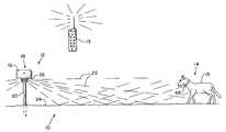
- FIG. 1is a perspective view of one embodiment of the wireless animal confinement system of the present invention
- FIG. 2is a top view of the containment transmitter assembly of FIG. 1;
- FIGS. 3A and 3Bare top views illustrating the various zones associated with the invention.
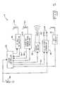
- FIG. 4is a schematic diagram of the containment transmitter assembly of FIG. 1;
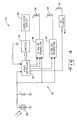
- FIG. 5is a schematic diagram of the receiver assembly of FIG. 1 .
- a wireless animal confinement system 10 of the present inventionincludes a containment transmitter assembly 12 , a training transmitter 13 , and a receiver assembly 14 shown attached to the collar of an animal 15 .
- the combination containment and training systemis useful, for example, to curb unwanted behavior (digging, barking etc.) while the animal is within a containment zone.
- containment transmitter assembly 12includes a transmitter device 16 having a solar unit 18 and being mounted on a substantially vertical post 20 .
- Solar unit 18includes a solar cell 28 connected to a storage battery 30 .
- the solar cell 28has sufficient output capability to power containment transmitter device 16 and charge the storage battery 30 simultaneously.
- the storage battery 30is capable of sourcing enough power for containment transmitter assembly 12 to permit reliable operation for extended periods when light is not available.
- the storage battery 30is a 4.5 ampere-hour battery.
- Transmitter device 16transmits signals 22 , which may be reflected off of ground surface 24 .
- Signals 22include both radio frequency (RF) reference signals (also referred to as synchronization signals) and lower frequency electromagnetic ranging signals.
- Containment transmitter assembly 12includes a audio/video display 26 for displaying information, such as a built in test status and battery charge level.
- RFradio frequency
- containment transmitter assembly 12 and receiver assembly 14cooperate to effectively divide the area surrounding containment transmitter assembly 12 into four zones: a confinement zone 100 , a low correction zone 102 , a high correction zone 104 and an outer, or OFF, zone 106 .
- zones 100 , 102 and 104are shown to be substantially circular, however, those skilled in the art will recognize that the actual shape of the perimeter of each of zones 100 , 102 and 104 will depend upon several factors, such as for example the amount and type of interference which may be experienced in the various zones, e.g., ground clutter.
- the four zones 100 , 102 , 104 and 106are defined in relation to the length of three radii, or distances, as measured from the location of containment transmitter assembly 12 : distance D 1 , distance D 2 , and distance D 3 .
- Distance D 1defines the perimeter of confinement zone 100 .
- Low correction zone 102is defined by the difference between perimeter distances D 1 and D 2 .
- High correction zone 104is defined by the difference between perimeter distances D 2 and D 3 .
- Outer zone 106is defined as any location beyond containment transmitter assembly 12 at a distance greater than distance D 3 .
- each of the distances D 1 , D 2 and D 3are defined based upon an associated signal strength of the received electromagnetic ranging signal.
- a tactile stimulatione.g., electrical shock or vibration
- animal 15will receive no further stimulation from receiver assembly 14 .
- animal 15ceases receiving correction stimuli once animal 15 exceeds the distance D 3 from the transmitter, to thereby spare animal 15 from unnecessary discomfort due to unproductive corrective stimulation.
- the animalre-enters the containment zone, no corrective stimulation is applied. This allows the animal to re-enter the desired confinement zone 100 area without being punished.
- the systemre-enables. Once the system re-enables, any attempt to exit the confinement zone 100 will result in stimulation as described previously in this paragraph.
- Both the transmitter 12 and receiver 14have built-in-test circuitry to check for internal hardware failures. If either containment transmitter assembly 12 or receiver assembly 14 suffer a hardware failure, receiver assembly 14 is structured such that animal 15 will not receive a stimulation.
- FIG. 3Billustrates a second boundary configuration that uses three zones: a confinement zone 200 , a correction zone 202 and an outer, or OFF, zone 204 .
- zones 200 and 202are shown to be substantially circular, however, those skilled in the art will recognize that the actual shape of the perimeter of each of zones 200 and 202 will depend upon several factors, such as for example the amount and type of interference which may be experienced in the various zones, e.g., ground clutter.
- the three zones 200 , 202 and 204are defined in relation to the length of two radii, or distances, as measured from the location of containment transmitter assembly 12 : distance D 4 and distance D 5 .
- Distance D 4defines the perimeter of confinement zone 200 .
- Correction zone 202is defined by the difference between perimeter distances D 4 and D 5 .
- Outer zone 204is defined as any location beyond containment transmitter assembly 12 at a distance greater than distance D 5 .
- each of the distances D 4 and D 5are defined based upon an associated signal strength of the received electromagnetic ranging signal.
- a progressively increasing tactile stimulatione.g., electrical shock or vibration
- animal 15ceases receiving correction stimuli once animal 15 exceeds the distance D 5 from the transmitter, to thereby spare animal 15 from unnecessary discomfort due to unproductive corrective stimulation. If, after the stimulation timeout has occurred, the animal re-enters the confinement zone 200 , no corrective stimulation is applied. This allows the animal to re-enter the desired confinement zone 200 without being punished. Once within confinement zone 200 for a predetermined time, the system re-enables. Once the system re-enables any attempt to exit the confinement zone 200 will result in stimulation as described previously in this paragraph.
- both the containment transmitter assembly 12 and receiver assembly 14have built-in-test circuitry to check for internal hardware failures. If either containment transmitter assembly 12 or receiver assembly 14 suffer a hardware failure, receiver assembly 14 is structured such that animal 15 will not receive a stimulation.
- transmitter device 16includes a microcontroller 32 which controls audio/video display 26 through an encoder 34 .
- Microcontroller 32also controls a transmitter 36 which transmits radio frequency (RF) synchronization signals via an antenna 38 .
- microcontroller 32controls electromagnetic ranging signal transmitter 40 in order to cause an omnidirectional electromagnetic signal to be transmitted from an antenna 42 .
- the microcontroller 32controls a Built-In-Test (BIT) circuit 43 that monitors and reports the health of the unit via an antenna 45 .
- BITBuilt-In-Test
- the RF synchronizing signal and the electromagnetic ranging signalare sequenced to a specific timetable to allow power consuming hardware to be enabled for the minimum amount of time required.
- An example of this time sequencingis described herein.
- a 114 milliscecond (ms) 16.529 kilohertz (kHz) electromagnetic ranging signal pulseis sent, followed by a 20 ms wide FM coded 27 megahertz (MHz) synchronization signal pulse sent 32 ms after the start of the ranging signal.
- These signalsare sent in bursts at a rate of approximately 4 bursts per second (every 0.25 seconds), which is the response latency of the system. Both signals are approximately omnidirectional.
- Transmitter 36transmits the 27 MHz synchronization signal to qualify/correlate the 16.529 kHz electromagnetic ranging signal pulse.
- the synchronization signalis uniquely coded with the Electronic ID of the system so that adjacent systems will not false alarm or interfere.
- the BIT circuitry 43monitors the output of the 16.529 kHz signal to verify that it is transmitted. If the BIT circuitry 43 does not receive a valid indication that the 16.529 kHz ranging signal is being sent, containment transmitter assembly 12 suspends transmission of the 27 MHz synchronization reference signal. The absence of the 27 MHz synchronization signal at the receiver prohibits activation of the stimulation circuitry.
- the approximately 4 burst per second transmit ratecould be staggered slightly for differently coded reference signals to help eliminate transmission collisions for co-located systems.
- the 27 MHz synchronization signaluses about 26 milliamps of current peak with the resulting average transmit current being approximately 2.1 milliamps.
- the 16.529 kHz electromagnetic ranging signaluses a peak current of approximately 9.2 milliamps with an average transmit current being approximately 4.3 milliaiips. With the remaining circuitry using an additional 500 microamps the total average current drain of the containment transmitter assembly 12 is 7.0 milliamps.
- using a solar array with 50 milliamp output capability along with a storage battery 30 of sufficient capacitywill permit containment transmitter assembly 12 to run continuously without interruption with a minimum of available sun light.
- receiver assembly 14includes an antenna 44 , a radio frequency receiver 46 , a microcontroller 48 , an antenna 52 , a superheterodyne narrow band receiver 54 , an audio driver 58 , a high voltage generator 60 , a BIT Circuit 61 and a battery 66 .
- the RF synchronization signal emitted by antenna 38 of containment transmitter assembly 12is received by antenna 44 of receiver assembly 14 .
- Receiver 46processes the RF synchronization signals received by antenna 44 that are on the frequency of the radio frequency signals produced by transmitter 36 , which is preferably 27 MHz.
- Receiver 46then sends the received data stream to microcontroller 48 on a data line 50 .
- the microcontroller 48then does the final processing on the signal to determine that a RF synchronization signal of the frequency of interest has been received.
- Antenna 52 of receiver assembly 14receives the electromagnetic ranging signal emitted by transmitter 40 .
- superheterodyne narrow band receiver 54sends a signal on data line 56 indicating to microcontroller 48 that an electromagnetic ranging signal within the narrow band of receiver 54 has been received.
- This narrow bandincludes the frequency of 16.529 kHz.
- each of antenna 44 and antenna 52is an omnidirectional antenna, and can be for example, a ferrite core or triplexer antenna.
- Microcontroller 48selectively turns on an audio driver 58 and/or a high voltage generator 60 dependent upon the detected signal strength of the received electromagnetic ranging signals, as described in more detail below.
- Audio driver 58drives a speaker 62 which emits an audible warning signal to the animal.
- high voltage generator 60Based on the control signals supplied by microcontroller 48 via conductor 63 , high voltage generator 60 selectively produces a voltage difference between probes 64 in order to apply an electrical stimulus to the animal when probes 64 are in contact with the body of animal 15 .
- receiver assembly 14can be attached to the dog's collar such that probes 64 are pressed or biased against the dogs fur and/or skin.
- Microcontroller 48 , audio driver 58 and high voltage generator 60are all powered by battery 66 , which may be a replaceable lithium battery with a capacity of 1400 milliamp hours.
- containment transmitter assembly 12is initialized to establish the desired containment radius D 1 /D 4 , which in turn is used to define the size of confinement zone 100 / 200 .
- the output power of the 16.529 kHz electromagnetic ranging signalis adjusted to provide the desired containment radius.
- the containment radius D 1 /D 4could be set at the receiver. This would be accomplished by having the transmitter output the ranging signal at a constant level which would yield the maximum containment radius for the system. The receiver would then be taken to a distance (D 1 /D 4 ) where the desired containment radius is to be set.
- the receiverwould then be put in a calibration mode and would sample the signal to noise ratio (SNR) at that point and store this value in memory. The receiver would then compare all future received ranging signals to this SNR value. If the SNR is greater than the stored value the receiver would assume it is inside the containment radius. If the SNR is below the stored value, the receiver would assume it is outside of the containment radius and tone/stimulate accordingly.
- SNRsignal to noise ratio
- Receiver assembly 14can use a 1400 milliamp-hour replaceable lithium battery 66 as its power source.
- Receiver 54can use a micropower 16 kHz current starved CMOS inverter amplifier, with a micropower MOSFET mixer to provide a 150 hertz center intermediate frequency (IF).
- the IFuses a micropower active filter op amp to provide the 10 hertz final bandwidth for optimum sensitivity and interference rejection.
- Total quiescent current for receiver 54is approximately 100 microamps.
- the 27 MHz reference receiver 46is time synchronized to the 27 MHz transmitter 36 and only powers up when a transmission is anticipated. This architecture minimizes the “on time” for 27 MHz receiver 46 and greatly reduces power consumption for the unit.
- receiver 46When receiver 46 is initially synchronized to transmitter 36 , receiver 46 is powered continuously until the 27 MHz synchronization signal is acquired. Once acquired, receiver 46 is powered up only once every 250 milliseconds to re-synchronize the anticipated reference radio signal. If the synchronization signal is lost for any reason, receiver 46 stays on to re-acquire it. With a peak current draw of 4 milliamps, the average reference receiver current is 450 microamps. Since microcontroller 48 uses a 32 kHz local oscillator clock, microcontroller current drain is only 10 microamps, with total quiescent current being 560 microamps. This yields approximately 90 days of continuous operation for receiver assembly 14 .
- receiver assembly 14After the FM coded 27 MHz synchronization signal is received by receiver assembly 14 , receiver assembly 14 then determines if the 16.529 kHz electromagnetic ranging pulse is present. If not present, the microcontroller determines that the receiver assembly 14 , and thus animal 15 , is out of the confinement zone and initiates a warning tone along with the lowest level tactile stimulation. This process is repeated with the tactile stimulation level increasing up to the maximum level unless the unit detects the presence of the 16.529 kHz ranging signal at the appropriate time in 4 successive windows. Once four successive decodes of the 16.529 kHz ranging signal are detected stimulation is stopped. Once twenty successive decodes of the 16.529 kHz ranging signal are detected the tactile stimulation level is reset to the lowest level. This sequencing allows the animal to re-enter the containment zone without receiving a correction.
- the confinement system 10operates in a manner to ensure that unproductive and/or unwarranted corrective signals are not applied to the animal.
- System 10is designed so that if a hardware failure occurs at either the transmitter or receiver, no false shock signal can be discerned with an uncorrelated 16.529 kHz electromagnetic signal reception.
- Such uncorrelated electromagnetic pulse receptionmay be from any of several high amplitude broad noise sources, e.g., car ignitions, televisions, appliances, etc.
- a time based filtering algorithmallows very tight windowing for anticipated electromagnetic ranging pulses, and ensures that the uncorrelated electromagnetic pulse reception is not regarded as an electromagnetic ranging signal emitted by containment transmitter assembly 12 .
- the receiver assembly 14is designed to accept signals from the separate and portable training transmitter 13 .
- Training transmitter 13can be a handheld transmitter operating at 27 MHz and capable of transmitting different data packets corresponding to different commands, such as those available from Innotek, Inc.
- the receiver assembly 14processes these commands received from training transmitter 13 and performs the desired action. These actions consist of applying different levels of tactile stimulation with or without an accompanying tone. Also, the unit may emit a tone without tactile stimulation.
- Receiver assembly 14is designed to work with the containment transmitter assembly 12 enabled alone, the training transmitter 13 enabled alone or both transmitters 12 , 13 enabled at the same time. When both transmitters 12 , 13 are enabled, an additional command sent from training transmitter 13 is a containment field disable command which can temporarily or permanently disable processing of the containment transmitter 12 signals within receiver assembly 14 .
- containment transmitter assembly 12has been described as transmitting a radio frequency synchronization (reference) signal and an electromagnetic ranging signal.
- the method and system of the present inventioncan be carried out with other types of signals which propagate through air, so long as the synchronization signal and the ranging signal are distinguishable and have signal strengths which permit different signal propagation distances.
- the radio frequency synchronization signalis transmitted during the electromagnetic ranging signal.
- the electromagnetic ranging signalcan also be transmitted before or after the radio frequency synchronization signal.
- the preferred tactile stimulus applied to the animalhas been described herein as an electrical shock.
- the stimuluscan also be any other type of unpleasant sensation or irritant, such as an audible tone, a smell, a spray, or a sensation caused by a mechanical device.
Landscapes
- Life Sciences & Earth Sciences (AREA)
- Environmental Sciences (AREA)
- Health & Medical Sciences (AREA)
- General Health & Medical Sciences (AREA)
- Physical Education & Sports Medicine (AREA)
- Animal Behavior & Ethology (AREA)
- Zoology (AREA)
- Animal Husbandry (AREA)
- Biodiversity & Conservation Biology (AREA)
- Catching Or Destruction (AREA)
Abstract
Description
Claims (35)
Priority Applications (1)
| Application Number | Priority Date | Filing Date | Title |
|---|---|---|---|
| US09/717,505US6431122B1 (en) | 2000-11-21 | 2000-11-21 | Wireless confinement and training system for an animal |
Applications Claiming Priority (1)
| Application Number | Priority Date | Filing Date | Title |
|---|---|---|---|
| US09/717,505US6431122B1 (en) | 2000-11-21 | 2000-11-21 | Wireless confinement and training system for an animal |
Publications (1)
| Publication Number | Publication Date |
|---|---|
| US6431122B1true US6431122B1 (en) | 2002-08-13 |
Family
ID=24882292
Family Applications (1)
| Application Number | Title | Priority Date | Filing Date |
|---|---|---|---|
| US09/717,505Expired - LifetimeUS6431122B1 (en) | 2000-11-21 | 2000-11-21 | Wireless confinement and training system for an animal |
Country Status (1)
| Country | Link |
|---|---|
| US (1) | US6431122B1 (en) |
Cited By (59)
| Publication number | Priority date | Publication date | Assignee | Title |
|---|---|---|---|---|
| US6581546B1 (en)* | 2002-02-14 | 2003-06-24 | Waters Instruments, Inc. | Animal containment system having a dynamically changing perimeter |
| US20040021574A1 (en)* | 2002-07-31 | 2004-02-05 | Radio Systems Corporation | Method and apparatus for testing an electronic pet containment transmitter |
| US20040066298A1 (en)* | 2002-06-28 | 2004-04-08 | Agri-Tech Electronics Lc | Animal control apparatus with ultrasonic link |
| US6774769B2 (en)* | 2001-05-23 | 2004-08-10 | Sanyo Seimitsu Corporation | Vibrating alert device |
| US20040216689A1 (en)* | 1999-11-10 | 2004-11-04 | Marshall Patrick T. | Apparatus and method for rotating avian enclosures |
| US6825768B2 (en)* | 2001-06-14 | 2004-11-30 | Dogwatch, Inc. | Adaptive pet containment system and method |
| US6830014B1 (en) | 2003-08-05 | 2004-12-14 | Tom Lalor | Animal collar |
| US20050065670A1 (en)* | 2003-08-13 | 2005-03-24 | Helmut Tripmaker | System and method for exchanging programs in aircraft computers |
| US20050061259A1 (en)* | 2003-08-05 | 2005-03-24 | Tom Lalor | Animal collar |
| US20050120978A1 (en)* | 2003-11-18 | 2005-06-09 | Tom Lalor | Automated animal return system |
| US20050235925A1 (en)* | 2003-11-18 | 2005-10-27 | Tom Lalor | Automated animal return system |
| US20050263100A1 (en)* | 2004-06-01 | 2005-12-01 | Kover Joseph Jr | Collarless pet containment system |
| US20060061469A1 (en)* | 2004-09-21 | 2006-03-23 | Skyfence Inc. | Positioning system that uses signals from a point source |
| US7046152B1 (en) | 2003-12-10 | 2006-05-16 | Innotek, Inc. | Method and apparatus for communicating control signals |
| US20060112905A1 (en)* | 2003-08-05 | 2006-06-01 | Tom Lalor | Animal collar |
| US7068174B1 (en) | 2003-12-10 | 2006-06-27 | Innotek, Inc. | Method and apparatus for communicating an animal control signal |
| US20060169222A1 (en)* | 2005-01-28 | 2006-08-03 | Gerig Duane A | Receiver collar |
| US7117822B1 (en) | 2003-12-10 | 2006-10-10 | Innotek, Inc. | Method and apparatus for communicating a randomized signal |
| WO2006053193A3 (en)* | 2004-11-10 | 2007-01-18 | Garden Guardian Inc | A device and method for controlling animal behavior |
| US7174855B2 (en) | 2004-05-06 | 2007-02-13 | Innotek, Inc. | Rising stimulation modification |
| US20070181078A1 (en)* | 2006-02-06 | 2007-08-09 | Mcfarland Scott A | Signal and protocol for remote dog trainer signaling with forward error correction |
| US20070186870A1 (en)* | 2006-01-24 | 2007-08-16 | Michael Westrick | Wireless confinement and training system for an animal |
| US20080180213A1 (en)* | 2006-11-07 | 2008-07-31 | Flax Stephen W | Digital Intercom Based Data Management System |
| US20080180256A1 (en)* | 2007-01-24 | 2008-07-31 | Richard Christian Caldwell | Method and remote motion-activated training apparatus to stop dogs from digging |
| US20080245316A1 (en)* | 2003-12-10 | 2008-10-09 | Radio Systems Corporation | Method and Apparatus for Varying Animal Correction Signals |
| US20090013939A1 (en)* | 2007-07-13 | 2009-01-15 | Whitlock International, L.L.C. | Apparatus and method for restricting movement of an animal into or out of a defined area |
| US20090119962A1 (en)* | 2007-11-13 | 2009-05-14 | Bruce De La Cruz | Methods and apparatuses for the display of promotional images |
| US20090199786A1 (en)* | 2008-02-13 | 2009-08-13 | Tom Lalor | Remote Control System for Controlling a Remote Animal Collar |
| US20090249677A1 (en)* | 2008-02-13 | 2009-10-08 | Tom Lalor | Remote control system for controlling a remote animal collar |
| US20090278669A1 (en)* | 2005-07-08 | 2009-11-12 | Martetschlaeger Stefan | Device for Protecting a Photovoltaic Plant Against Rodent Bite Damage |
| US7801575B1 (en)* | 2010-03-19 | 2010-09-21 | Callaway Golf Company | Method and system for shot tracking |
| US7911186B1 (en)* | 2010-04-07 | 2011-03-22 | Callaway Golf Company | Method and system for shot tracking |
| US7915865B1 (en)* | 2010-04-28 | 2011-03-29 | Callaway Golf Company | Method and system for shot tracking |
| US20110151986A1 (en)* | 2009-12-17 | 2011-06-23 | Callaway Golf Company | Method and system for shot tracking |
| US20110234410A1 (en)* | 2010-03-25 | 2011-09-29 | Groh William S | Solar Powered Animal Containment/Repellent System |
| US20120000431A1 (en)* | 2010-07-05 | 2012-01-05 | Kamran Khoshkish | Electronic Pet Containment System |
| US20130092099A1 (en)* | 2011-10-18 | 2013-04-18 | Titan Pet Products, Inc. | Systems and methods for animal containment and premises monitoring |
| US9247714B1 (en)* | 2014-09-15 | 2016-02-02 | Shawn Tait | Animal deterrent and training device and method thereof |
| US20160205899A1 (en)* | 2010-02-01 | 2016-07-21 | Perimeter Technologies, Inc. | Time of flight animal monitoring |
| WO2017072749A1 (en)* | 2015-10-26 | 2017-05-04 | Sion Ltd. | System and method for animal control |
| US10154651B2 (en) | 2011-12-05 | 2018-12-18 | Radio Systems Corporation | Integrated dog tracking and stimulus delivery system |
| US10231440B2 (en) | 2015-06-16 | 2019-03-19 | Radio Systems Corporation | RF beacon proximity determination enhancement |
| US10433526B2 (en)* | 2018-02-22 | 2019-10-08 | Jollee, LLC | Pet location monitoring and deterrent system |
| US10514439B2 (en) | 2017-12-15 | 2019-12-24 | Radio Systems Corporation | Location based wireless pet containment system using single base unit |
| US10613559B2 (en) | 2016-07-14 | 2020-04-07 | Radio Systems Corporation | Apparatus, systems and methods for generating voltage excitation waveforms |
| US10645908B2 (en) | 2015-06-16 | 2020-05-12 | Radio Systems Corporation | Systems and methods for providing a sound masking environment |
| US10674709B2 (en) | 2011-12-05 | 2020-06-09 | Radio Systems Corporation | Piezoelectric detection coupling of a bark collar |
| US10842128B2 (en) | 2017-12-12 | 2020-11-24 | Radio Systems Corporation | Method and apparatus for applying, monitoring, and adjusting a stimulus to a pet |
| US10986813B2 (en) | 2017-12-12 | 2021-04-27 | Radio Systems Corporation | Method and apparatus for applying, monitoring, and adjusting a stimulus to a pet |
| US11109182B2 (en) | 2017-02-27 | 2021-08-31 | Radio Systems Corporation | Threshold barrier system |
| US11166435B2 (en)* | 2019-05-28 | 2021-11-09 | WAGZ, Inc. | Methods and systems for deterring animals to approach or enter identified zones |
| US11238889B2 (en) | 2019-07-25 | 2022-02-01 | Radio Systems Corporation | Systems and methods for remote multi-directional bark deterrence |
| US11372077B2 (en) | 2017-12-15 | 2022-06-28 | Radio Systems Corporation | Location based wireless pet containment system using single base unit |
| US11394196B2 (en) | 2017-11-10 | 2022-07-19 | Radio Systems Corporation | Interactive application to protect pet containment systems from external surge damage |
| US11470814B2 (en) | 2011-12-05 | 2022-10-18 | Radio Systems Corporation | Piezoelectric detection coupling of a bark collar |
| US11490597B2 (en) | 2020-07-04 | 2022-11-08 | Radio Systems Corporation | Systems, methods, and apparatus for establishing keep out zones within wireless containment regions |
| US11553692B2 (en) | 2011-12-05 | 2023-01-17 | Radio Systems Corporation | Piezoelectric detection coupling of a bark collar |
| US12171192B1 (en) | 2022-02-14 | 2024-12-24 | GPSip, Inc. | Graphical shepherding |
| US12292527B2 (en) | 2013-03-15 | 2025-05-06 | Radio Systems Corporation | Integrated apparatus and method to combine a wireless fence collar with GPS tracking capability |
Citations (19)
| Publication number | Priority date | Publication date | Assignee | Title |
|---|---|---|---|---|
| US4898120A (en)* | 1988-06-16 | 1990-02-06 | Torrington Product Ventures, Inc. | Animal training and restraining system |
| US4967695A (en) | 1989-06-23 | 1990-11-06 | Invisible Fence Company, Inc. | System for controlling the movement of an animal |
| US5067441A (en)* | 1990-12-10 | 1991-11-26 | Torrington Product Ventures, Inc. | Electronic assembly for restricting animals to defined areas |
| US5381129A (en) | 1994-03-23 | 1995-01-10 | Radio Systems, Inc. | Wireless pet containment system |
| US5425330A (en) | 1993-08-19 | 1995-06-20 | Invisible Fence Company, Inc. | Animal control device |
| US5435271A (en) | 1993-08-19 | 1995-07-25 | Invisible Fence Company, Inc. | Multi-channel animal control device with external data communication |
| US5460124A (en) | 1993-07-15 | 1995-10-24 | Perimeter Technologies Incorporated | Receiver for an electronic animal confinement system |
| US5559498A (en)* | 1994-12-30 | 1996-09-24 | Innotek Inc. | Combination confinement and remote training system |
| US5576694A (en) | 1995-05-24 | 1996-11-19 | Invisible Fence Company, Inc. | Electronic animal control system with masking signal generator |
| US5606936A (en)* | 1995-04-25 | 1997-03-04 | Davis; James E. | Animal restraining system |
| US5642690A (en)* | 1986-01-21 | 1997-07-01 | Industrial Automation Technologies, Inc. | Animal containment system |
| US5852403A (en) | 1994-03-23 | 1998-12-22 | Radio Systems Corporation | Wireless pet containment system |
| US5872516A (en)* | 1994-02-22 | 1999-02-16 | Bonge, Jr.; Nicholas J. | Ultrasonic transceiver and remote controlled devices for pets |
| US5913284A (en)* | 1996-02-27 | 1999-06-22 | Innotek, Inc. | Stimulation device and technique |
| US6019066A (en)* | 1998-03-16 | 2000-02-01 | Taylor; Todd T. | Animal confinement/training system |
| US6114957A (en)* | 1998-02-19 | 2000-09-05 | Innotek Pet Products, Inc. | Pet locator system |
| US6163261A (en)* | 1999-06-01 | 2000-12-19 | Innotek Pet Products, Inc. | Wireless pet confinement system |
| US6232880B1 (en)* | 1999-07-14 | 2001-05-15 | The United States Of America As Represented By The Secretary Of Agriculture | Animal control system using global positioning and instrumental animal conditioning |
| US6271757B1 (en)* | 1997-12-19 | 2001-08-07 | Invisible Fence, Inc. | Satellite animal containment system with programmable Boundaries |
- 2000
- 2000-11-21USUS09/717,505patent/US6431122B1/ennot_activeExpired - Lifetime
Patent Citations (20)
| Publication number | Priority date | Publication date | Assignee | Title |
|---|---|---|---|---|
| US5642690A (en)* | 1986-01-21 | 1997-07-01 | Industrial Automation Technologies, Inc. | Animal containment system |
| US4898120A (en)* | 1988-06-16 | 1990-02-06 | Torrington Product Ventures, Inc. | Animal training and restraining system |
| US4967695A (en) | 1989-06-23 | 1990-11-06 | Invisible Fence Company, Inc. | System for controlling the movement of an animal |
| US5067441A (en)* | 1990-12-10 | 1991-11-26 | Torrington Product Ventures, Inc. | Electronic assembly for restricting animals to defined areas |
| US5460124A (en) | 1993-07-15 | 1995-10-24 | Perimeter Technologies Incorporated | Receiver for an electronic animal confinement system |
| US5682839A (en) | 1993-07-15 | 1997-11-04 | Perimeter Technologies Incorporated | Electronic animal confinement system |
| US5435271A (en) | 1993-08-19 | 1995-07-25 | Invisible Fence Company, Inc. | Multi-channel animal control device with external data communication |
| US5425330A (en) | 1993-08-19 | 1995-06-20 | Invisible Fence Company, Inc. | Animal control device |
| US5872516A (en)* | 1994-02-22 | 1999-02-16 | Bonge, Jr.; Nicholas J. | Ultrasonic transceiver and remote controlled devices for pets |
| US5381129A (en) | 1994-03-23 | 1995-01-10 | Radio Systems, Inc. | Wireless pet containment system |
| US5852403A (en) | 1994-03-23 | 1998-12-22 | Radio Systems Corporation | Wireless pet containment system |
| US5559498A (en)* | 1994-12-30 | 1996-09-24 | Innotek Inc. | Combination confinement and remote training system |
| US5606936A (en)* | 1995-04-25 | 1997-03-04 | Davis; James E. | Animal restraining system |
| US5576694A (en) | 1995-05-24 | 1996-11-19 | Invisible Fence Company, Inc. | Electronic animal control system with masking signal generator |
| US5913284A (en)* | 1996-02-27 | 1999-06-22 | Innotek, Inc. | Stimulation device and technique |
| US6271757B1 (en)* | 1997-12-19 | 2001-08-07 | Invisible Fence, Inc. | Satellite animal containment system with programmable Boundaries |
| US6114957A (en)* | 1998-02-19 | 2000-09-05 | Innotek Pet Products, Inc. | Pet locator system |
| US6019066A (en)* | 1998-03-16 | 2000-02-01 | Taylor; Todd T. | Animal confinement/training system |
| US6163261A (en)* | 1999-06-01 | 2000-12-19 | Innotek Pet Products, Inc. | Wireless pet confinement system |
| US6232880B1 (en)* | 1999-07-14 | 2001-05-15 | The United States Of America As Represented By The Secretary Of Agriculture | Animal control system using global positioning and instrumental animal conditioning |
Cited By (93)
| Publication number | Priority date | Publication date | Assignee | Title |
|---|---|---|---|---|
| US20040216689A1 (en)* | 1999-11-10 | 2004-11-04 | Marshall Patrick T. | Apparatus and method for rotating avian enclosures |
| US7066109B2 (en)* | 1999-11-10 | 2006-06-27 | Birdquest, Llc | Apparatus and method for rotating avian enclosures |
| US6774769B2 (en)* | 2001-05-23 | 2004-08-10 | Sanyo Seimitsu Corporation | Vibrating alert device |
| US6825768B2 (en)* | 2001-06-14 | 2004-11-30 | Dogwatch, Inc. | Adaptive pet containment system and method |
| WO2003069363A3 (en)* | 2002-02-14 | 2004-02-12 | Waters Instr Inc | Animal containment system having a dynamically changing perimeter |
| US6581546B1 (en)* | 2002-02-14 | 2003-06-24 | Waters Instruments, Inc. | Animal containment system having a dynamically changing perimeter |
| US6956483B2 (en)* | 2002-06-28 | 2005-10-18 | Agri-Tech Electronics Lc | Animal control apparatus with ultrasonic link |
| US20040066298A1 (en)* | 2002-06-28 | 2004-04-08 | Agri-Tech Electronics Lc | Animal control apparatus with ultrasonic link |
| US20040021574A1 (en)* | 2002-07-31 | 2004-02-05 | Radio Systems Corporation | Method and apparatus for testing an electronic pet containment transmitter |
| US6838991B2 (en)* | 2002-07-31 | 2005-01-04 | Radio Systems Corporation | Method and apparatus for testing an electronic pet containment transmitter |
| US20050061259A1 (en)* | 2003-08-05 | 2005-03-24 | Tom Lalor | Animal collar |
| US7267082B2 (en) | 2003-08-05 | 2007-09-11 | Tom Lalor | Animal collar |
| US7562640B2 (en) | 2003-08-05 | 2009-07-21 | Tom Lalor | Animal collar |
| US7243617B2 (en) | 2003-08-05 | 2007-07-17 | Tom Lalor | Animal collar |
| US20060112905A1 (en)* | 2003-08-05 | 2006-06-01 | Tom Lalor | Animal collar |
| US20080210176A1 (en)* | 2003-08-05 | 2008-09-04 | Tom Lalor | Animal collar |
| US6830014B1 (en) | 2003-08-05 | 2004-12-14 | Tom Lalor | Animal collar |
| US20050065670A1 (en)* | 2003-08-13 | 2005-03-24 | Helmut Tripmaker | System and method for exchanging programs in aircraft computers |
| US20050120978A1 (en)* | 2003-11-18 | 2005-06-09 | Tom Lalor | Automated animal return system |
| US20090025651A1 (en)* | 2003-11-18 | 2009-01-29 | Tom Lalor | Automated animal return system |
| US20050235925A1 (en)* | 2003-11-18 | 2005-10-27 | Tom Lalor | Automated animal return system |
| US8342135B2 (en) | 2003-12-10 | 2013-01-01 | Radio Systems Corporation | Method and apparatus for varying animal correction signals |
| US7117822B1 (en) | 2003-12-10 | 2006-10-10 | Innotek, Inc. | Method and apparatus for communicating a randomized signal |
| US7495570B1 (en) | 2003-12-10 | 2009-02-24 | Innotek, Inc. | Transmitter apparatus |
| US7204204B1 (en) | 2003-12-10 | 2007-04-17 | Innotek, Inc. | Method for creating an avoidance zone |
| US20080245316A1 (en)* | 2003-12-10 | 2008-10-09 | Radio Systems Corporation | Method and Apparatus for Varying Animal Correction Signals |
| US7068174B1 (en) | 2003-12-10 | 2006-06-27 | Innotek, Inc. | Method and apparatus for communicating an animal control signal |
| US7278376B1 (en)* | 2003-12-10 | 2007-10-09 | Innotek, Inc. | Method of transmitting a signal for controlling an animal |
| US7046152B1 (en) | 2003-12-10 | 2006-05-16 | Innotek, Inc. | Method and apparatus for communicating control signals |
| US7174855B2 (en) | 2004-05-06 | 2007-02-13 | Innotek, Inc. | Rising stimulation modification |
| US20070101948A1 (en)* | 2004-05-06 | 2007-05-10 | Innotek, Inc. | Rising stimulation modification |
| US20070101949A1 (en)* | 2004-05-06 | 2007-05-10 | Innotek, Inc. | Rising stimulation modification |
| US7360505B2 (en) | 2004-05-06 | 2008-04-22 | Innotek, Inc. | Rising stimulation modification |
| US7343879B2 (en) | 2004-05-06 | 2008-03-18 | Innotek, Inc. | Rising stimulation modification |
| US20050263100A1 (en)* | 2004-06-01 | 2005-12-01 | Kover Joseph Jr | Collarless pet containment system |
| US20060061469A1 (en)* | 2004-09-21 | 2006-03-23 | Skyfence Inc. | Positioning system that uses signals from a point source |
| US20080314334A1 (en)* | 2004-11-10 | 2008-12-25 | Garden Guardian, Inc. | Device and Method for Controlling Animal Behavior |
| WO2006053193A3 (en)* | 2004-11-10 | 2007-01-18 | Garden Guardian Inc | A device and method for controlling animal behavior |
| US20060169222A1 (en)* | 2005-01-28 | 2006-08-03 | Gerig Duane A | Receiver collar |
| US20070137589A1 (en)* | 2005-01-28 | 2007-06-21 | Innotek, Inc. | Receiver collar |
| US7345588B2 (en)* | 2005-01-28 | 2008-03-18 | Innotek, Inc. | Receiver collar |
| US7394390B2 (en)* | 2005-01-28 | 2008-07-01 | Radio Systems Corporation | Receiver collar |
| US20090278669A1 (en)* | 2005-07-08 | 2009-11-12 | Martetschlaeger Stefan | Device for Protecting a Photovoltaic Plant Against Rodent Bite Damage |
| US8081065B2 (en)* | 2005-07-08 | 2011-12-20 | Fronius International Gmbh | Device for protecting a photovoltaic plant against rodent bite damage |
| US20070186870A1 (en)* | 2006-01-24 | 2007-08-16 | Michael Westrick | Wireless confinement and training system for an animal |
| US7647545B2 (en)* | 2006-02-06 | 2010-01-12 | Radio Systems Corporation | Signal and protocol for remote dog trainer signaling with a forward error correction |
| US20070181078A1 (en)* | 2006-02-06 | 2007-08-09 | Mcfarland Scott A | Signal and protocol for remote dog trainer signaling with forward error correction |
| US20080180213A1 (en)* | 2006-11-07 | 2008-07-31 | Flax Stephen W | Digital Intercom Based Data Management System |
| US20080180218A1 (en)* | 2006-11-07 | 2008-07-31 | Flax Stephen W | Bi-Modal Remote Identification System |
| US20080180256A1 (en)* | 2007-01-24 | 2008-07-31 | Richard Christian Caldwell | Method and remote motion-activated training apparatus to stop dogs from digging |
| US20090013939A1 (en)* | 2007-07-13 | 2009-01-15 | Whitlock International, L.L.C. | Apparatus and method for restricting movement of an animal into or out of a defined area |
| US20090119962A1 (en)* | 2007-11-13 | 2009-05-14 | Bruce De La Cruz | Methods and apparatuses for the display of promotional images |
| US20090249677A1 (en)* | 2008-02-13 | 2009-10-08 | Tom Lalor | Remote control system for controlling a remote animal collar |
| US20090199786A1 (en)* | 2008-02-13 | 2009-08-13 | Tom Lalor | Remote Control System for Controlling a Remote Animal Collar |
| US8336245B2 (en) | 2008-02-13 | 2012-12-25 | Alpine Trust | Remote control system for controlling a remote animal collar |
| US8365684B2 (en)* | 2008-02-13 | 2013-02-05 | Apline Trust | Remote control system for controlling a remote animal collar |
| US20110151986A1 (en)* | 2009-12-17 | 2011-06-23 | Callaway Golf Company | Method and system for shot tracking |
| US9730430B2 (en)* | 2010-02-01 | 2017-08-15 | Perimeter Technologies Inc | Time of flight animal monitoring |
| US20160205899A1 (en)* | 2010-02-01 | 2016-07-21 | Perimeter Technologies, Inc. | Time of flight animal monitoring |
| US7801575B1 (en)* | 2010-03-19 | 2010-09-21 | Callaway Golf Company | Method and system for shot tracking |
| US7853211B1 (en)* | 2010-03-19 | 2010-12-14 | Callaway Golf Company | Method and system for shot tracking |
| US20110234410A1 (en)* | 2010-03-25 | 2011-09-29 | Groh William S | Solar Powered Animal Containment/Repellent System |
| WO2011119568A1 (en)* | 2010-03-25 | 2011-09-29 | Radio Systems Corporation | Solar powered animal containment/repellant system |
| US7911186B1 (en)* | 2010-04-07 | 2011-03-22 | Callaway Golf Company | Method and system for shot tracking |
| US8120332B2 (en)* | 2010-04-28 | 2012-02-21 | Callaway Golf Company | Method and system for shot tracking |
| US7915865B1 (en)* | 2010-04-28 | 2011-03-29 | Callaway Golf Company | Method and system for shot tracking |
| US20120000431A1 (en)* | 2010-07-05 | 2012-01-05 | Kamran Khoshkish | Electronic Pet Containment System |
| US20130092099A1 (en)* | 2011-10-18 | 2013-04-18 | Titan Pet Products, Inc. | Systems and methods for animal containment and premises monitoring |
| US10674709B2 (en) | 2011-12-05 | 2020-06-09 | Radio Systems Corporation | Piezoelectric detection coupling of a bark collar |
| US10154651B2 (en) | 2011-12-05 | 2018-12-18 | Radio Systems Corporation | Integrated dog tracking and stimulus delivery system |
| US11553692B2 (en) | 2011-12-05 | 2023-01-17 | Radio Systems Corporation | Piezoelectric detection coupling of a bark collar |
| US11470814B2 (en) | 2011-12-05 | 2022-10-18 | Radio Systems Corporation | Piezoelectric detection coupling of a bark collar |
| US12292527B2 (en) | 2013-03-15 | 2025-05-06 | Radio Systems Corporation | Integrated apparatus and method to combine a wireless fence collar with GPS tracking capability |
| US9247714B1 (en)* | 2014-09-15 | 2016-02-02 | Shawn Tait | Animal deterrent and training device and method thereof |
| US10231440B2 (en) | 2015-06-16 | 2019-03-19 | Radio Systems Corporation | RF beacon proximity determination enhancement |
| US12089565B2 (en) | 2015-06-16 | 2024-09-17 | Radio Systems Corporation | Systems and methods for monitoring a subject in a premise |
| US10645908B2 (en) | 2015-06-16 | 2020-05-12 | Radio Systems Corporation | Systems and methods for providing a sound masking environment |
| US10357022B2 (en)* | 2015-10-26 | 2019-07-23 | Sionet Ltd. | System and method for animal control |
| WO2017072749A1 (en)* | 2015-10-26 | 2017-05-04 | Sion Ltd. | System and method for animal control |
| US10613559B2 (en) | 2016-07-14 | 2020-04-07 | Radio Systems Corporation | Apparatus, systems and methods for generating voltage excitation waveforms |
| US11109182B2 (en) | 2017-02-27 | 2021-08-31 | Radio Systems Corporation | Threshold barrier system |
| US11394196B2 (en) | 2017-11-10 | 2022-07-19 | Radio Systems Corporation | Interactive application to protect pet containment systems from external surge damage |
| US10842128B2 (en) | 2017-12-12 | 2020-11-24 | Radio Systems Corporation | Method and apparatus for applying, monitoring, and adjusting a stimulus to a pet |
| US10986813B2 (en) | 2017-12-12 | 2021-04-27 | Radio Systems Corporation | Method and apparatus for applying, monitoring, and adjusting a stimulus to a pet |
| US11372077B2 (en) | 2017-12-15 | 2022-06-28 | Radio Systems Corporation | Location based wireless pet containment system using single base unit |
| US10514439B2 (en) | 2017-12-15 | 2019-12-24 | Radio Systems Corporation | Location based wireless pet containment system using single base unit |
| US12044791B2 (en) | 2017-12-15 | 2024-07-23 | Radio Systems Corporation | Location based wireless pet containment system using single base unit |
| US10955521B2 (en) | 2017-12-15 | 2021-03-23 | Radio Systems Corporation | Location based wireless pet containment system using single base unit |
| US10433526B2 (en)* | 2018-02-22 | 2019-10-08 | Jollee, LLC | Pet location monitoring and deterrent system |
| US11166435B2 (en)* | 2019-05-28 | 2021-11-09 | WAGZ, Inc. | Methods and systems for deterring animals to approach or enter identified zones |
| US11238889B2 (en) | 2019-07-25 | 2022-02-01 | Radio Systems Corporation | Systems and methods for remote multi-directional bark deterrence |
| US11490597B2 (en) | 2020-07-04 | 2022-11-08 | Radio Systems Corporation | Systems, methods, and apparatus for establishing keep out zones within wireless containment regions |
| US12171192B1 (en) | 2022-02-14 | 2024-12-24 | GPSip, Inc. | Graphical shepherding |
Similar Documents
| Publication | Publication Date | Title |
|---|---|---|
| US6431122B1 (en) | Wireless confinement and training system for an animal | |
| US6163261A (en) | Wireless pet confinement system | |
| US7421979B2 (en) | Electronic fence capable of guiding animals to return | |
| US8297233B2 (en) | Radial-shape wireless dog fence system and method | |
| CA1339752C (en) | Animal training and restraining system | |
| US5565850A (en) | Electronic confinement system for animals using modulated radio waves | |
| US5868103A (en) | Method and apparatus for controlling an animal | |
| US5799618A (en) | Combination confinement system and bark inhibitor | |
| WO2007019206A2 (en) | Pet confinement system using ultra wideband | |
| US7081821B2 (en) | Electronic fence system and controlling method thereof | |
| US6561137B2 (en) | Portable electronic multi-sensory animal containment and tracking device | |
| US6114957A (en) | Pet locator system | |
| US7477155B2 (en) | Animal containment system with monitor | |
| US6079367A (en) | Animal training apparatus and method | |
| US6230661B1 (en) | External battery arrangement for electronic containment systems | |
| US7360505B2 (en) | Rising stimulation modification | |
| JP2010516248A (en) | Animal electron confinement system to determine approach direction | |
| US5170149A (en) | Confinement arrangement for animals | |
| WO1996030882A1 (en) | Wireless pet containment system | |
| US5610588A (en) | Electronic confinement system for animals using modulated radio waves | |
| RU2503436C1 (en) | Method for space orientation, navigation and information in individuals suffering visual dysfunctions and system for implementation thereof | |
| US9877892B2 (en) | System and method for titrating in vivo cellular reaction and gene expression using varying oscillation frequencies | |
| CN208047707U (en) | GPS pet fence training aids | |
| US6147610A (en) | External deterrent arrangement for electronic containment systems | |
| RU2792365C1 (en) | Personal wearable siren (pws) |
Legal Events
| Date | Code | Title | Description |
|---|---|---|---|
| AS | Assignment | Owner name:INNOTEK, INC., INDIANA Free format text:ASSIGNMENT OF ASSIGNORS INTEREST;ASSIGNORS:WESTRICK, MICHAEL D.;MADDOX, SCOTT E.;JOHNSON, PETER F.;AND OTHERS;REEL/FRAME:011320/0083 Effective date:20001120 | |
| STCF | Information on status: patent grant | Free format text:PATENTED CASE | |
| AS | Assignment | Owner name:NATIONAL CITY BANK, OHIO Free format text:SECURITY AGREEMENT;ASSIGNOR:INNOTEK, INC.;REEL/FRAME:016580/0060 Effective date:20010125 | |
| FPAY | Fee payment | Year of fee payment:4 | |
| SULP | Surcharge for late payment | ||
| AS | Assignment | Owner name:FIFTH THIRD BANK, AS ADMINISTRATIVE AGENT,OHIO Free format text:SECURITY INTEREST;ASSIGNOR:INNOTEK, INC.;REEL/FRAME:018291/0913 Effective date:20060915 Owner name:FIFTH THIRD BANK, AS ADMINISTRATIVE AGENT, OHIO Free format text:SECURITY INTEREST;ASSIGNOR:INNOTEK, INC.;REEL/FRAME:018291/0913 Effective date:20060915 | |
| AS | Assignment | Owner name:INNOTEK, INC., INDIANA Free format text:RELEASE OF ASSIGNMENT;ASSIGNOR:NATIONAL CITY BANK;REEL/FRAME:018323/0501 Effective date:20060915 | |
| AS | Assignment | Owner name:INNOTEK, INC., INDIANA Free format text:RELEASE OF SECURITY AGREEMENT RECORDED ON SEPTEMBER 23, 2005 AT REEL/FRAME NO. 016580/0060;ASSIGNOR:NATIONAL CITY BANK;REEL/FRAME:018303/0629 Effective date:20060914 | |
| FPAY | Fee payment | Year of fee payment:8 | |
| FEPP | Fee payment procedure | Free format text:PAT HOLDER NO LONGER CLAIMS SMALL ENTITY STATUS, ENTITY STATUS SET TO UNDISCOUNTED (ORIGINAL EVENT CODE: STOL); ENTITY STATUS OF PATENT OWNER: LARGE ENTITY | |
| AS | Assignment | Owner name:THE BANK OF NEW YORK MELLON TRUST COMPANY, N.A., F Free format text:SECURITY AGREEMENT;ASSIGNORS:RADIO SYSTEMS CORPORATION;INNOTEK, INC.;INVISIBLE FENCE, INC.;REEL/FRAME:029308/0434 Effective date:20121023 Owner name:THE BANK OF NEW YORK MELLON TRUST COMPANY, N.A., F Free format text:SECURITY AGREEMENT;ASSIGNORS:RADIO SYSTEMS CORPORATION;INNOTEK, INC.;INVISIBLE FENCE, INC.;REEL/FRAME:029308/0001 Effective date:20121023 | |
| FPAY | Fee payment | Year of fee payment:12 | |
| AS | Assignment | Owner name:THE BANK OF NEW YORK MELLON TRUST COMPANY, N.A., F Free format text:CORRECTIVE ASSIGNMENT TO CORRECT THE ASSIGNMENT DOCUMENT WHICH INCORRECTLY IDENTIFIED PATENT APP. NO. 13/302,477 PREVIOUSLY RECORDED ON REEL 029308 FRAME 0001. ASSIGNOR(S) HEREBY CONFIRMS THE SECURITY INTEREST;ASSIGNORS:RADIO SYSTEMS CORPORATION;INVISIBLE FENCE, INC.;INNOTEK, INC.;REEL/FRAME:037127/0491 Effective date:20150929 | |
| AS | Assignment | Owner name:THE BANK OF NEW YORK MELLON TRUST COMPANY, N.A., F Free format text:CORRECTIVE ASSIGNMENT TO CORRECT THE INCORRECT PATENT NO. 7814565 PREVIOUSLY RECORDED AT REEL: 029308 FRAME: 0001. ASSIGNOR(S) HEREBY CONFIRMS THE SECURITY AGREEMENT;ASSIGNORS:RADIO SYSTEMS CORPORATION;INNOTEK, INC.;INVISIBLE FENCE, INC.;REEL/FRAME:038332/0343 Effective date:20121023 | |
| AS | Assignment | Owner name:THE BANK OF NEW YORK MELLON TRUST COMPANY, N.A., F Free format text:CORRECTIVE ASSIGNMENT TO CORRECT THE INCORRECT PATENT NO. 7814565 PREVIOUSLY RECORDED AT REEL: 037127 FRAME: 0491. ASSIGNOR(S) HEREBY CONFIRMS THE SECURITY INTEREST;ASSIGNORS:RADIO SYSTEMS CORPORATION;INVISIBLE FENCE, INC.;INNOTEK, INC.;REEL/FRAME:038601/0757 Effective date:20150929 | |
| AS | Assignment | Owner name:FIFTH THIRD BANK, AS ADMINISTRATIVE AGENT, OHIO Free format text:SECURITY AGREEMENT;ASSIGNOR:INNOTEK, INC.;REEL/FRAME:042409/0945 Effective date:20170502 | |
| AS | Assignment | Owner name:INVISIBLE FENCE, INC., TENNESSEE Free format text:RELEASE BY SECURED PARTY;ASSIGNOR:THE BANK OF NEW YORK MELLON TRUST COMPANY, N.A.;REEL/FRAME:043038/0291 Effective date:20170502 Owner name:RADIO SYSTEMS CORPORATION, TENNESSEE Free format text:RELEASE BY SECURED PARTY;ASSIGNOR:THE BANK OF NEW YORK MELLON TRUST COMPANY, N.A.;REEL/FRAME:043038/0291 Effective date:20170502 Owner name:INNOTEK, INC., TENNESSEE Free format text:RELEASE BY SECURED PARTY;ASSIGNOR:THE BANK OF NEW YORK MELLON TRUST COMPANY, N.A.;REEL/FRAME:043038/0291 Effective date:20170502 | |
| AS | Assignment | Owner name:RADIO SYSTEMS CORPORATION, TENNESSEE Free format text:ASSIGNMENT OF ASSIGNORS INTEREST;ASSIGNOR:INNOTEK, INC.;REEL/FRAME:052926/0847 Effective date:20200610 | |
| AS | Assignment | Owner name:FIFTH THIRD BANK, N.A., AS COLLATERAL AGENT, OHIO Free format text:SECURITY AGREEMENT;ASSIGNORS:RADIO SYSTEMS CORPORATION;INNOTEK, INC.;REEL/FRAME:053116/0599 Effective date:20200701 Owner name:WILMINGTON TRUST, NATIONAL ASSOCIATION, MINNESOTA Free format text:NOTICE OF CONFIRMATION OF GRANT OF SECURITY INTEREST IN PATENTS;ASSIGNORS:INNOTEK, INC.;RADIO SYSTEMS CORPORATION;REEL/FRAME:053117/0189 Effective date:20200701 | |
| AS | Assignment | Owner name:PREMIER PET PRODUCTS, LLC, TENNESSEE Free format text:RELEASE OF SECURITY INTEREST IN PATENTS;ASSIGNOR:FIFTH THIRD BANK;REEL/FRAME:053122/0268 Effective date:20200701 Owner name:PREMIER PET PRODUCTS, LLC, TENNESSEE Free format text:RELEASE OF SECURITY INTEREST IN PATENTS;ASSIGNOR:FIFTH THIRD BANK;REEL/FRAME:053122/0453 Effective date:20200701 Owner name:INNOTEK, INC., TENNESSEE Free format text:RELEASE OF SECURITY INTEREST IN PATENTS;ASSIGNOR:FIFTH THIRD BANK;REEL/FRAME:053122/0268 Effective date:20200701 Owner name:INNOTEK, INC., TENNESSEE Free format text:RELEASE OF SECURITY INTEREST IN PATENTS;ASSIGNOR:FIFTH THIRD BANK;REEL/FRAME:053122/0378 Effective date:20200701 Owner name:INVISIBLE FENCE, INC., TENNESSEE Free format text:RELEASE OF SECURITY INTEREST IN PATENTS;ASSIGNOR:FIFTH THIRD BANK;REEL/FRAME:053122/0453 Effective date:20200701 Owner name:RADIO SYSTEMS CORPORATION, TENNESSEE Free format text:RELEASE OF SECURITY INTEREST IN PATENTS;ASSIGNOR:FIFTH THIRD BANK;REEL/FRAME:053122/0268 Effective date:20200701 Owner name:INVISIBLE FENCE, INC., TENNESSEE Free format text:RELEASE OF SECURITY INTEREST IN PATENTS;ASSIGNOR:FIFTH THIRD BANK;REEL/FRAME:053122/0378 Effective date:20200701 Owner name:PREMIER PET PRODUCTS, LLC, TENNESSEE Free format text:RELEASE OF SECURITY INTEREST IN PATENTS;ASSIGNOR:FIFTH THIRD BANK;REEL/FRAME:053122/0344 Effective date:20200701 Owner name:RADIO SYSTEMS CORPORATION, TENNESSEE Free format text:RELEASE OF SECURITY INTEREST IN PATENTS;ASSIGNOR:FIFTH THIRD BANK;REEL/FRAME:053122/0453 Effective date:20200701 Owner name:RADIO SYSTEMS CORPORATION, TENNESSEE Free format text:RELEASE OF SECURITY INTEREST IN PATENTS;ASSIGNOR:FIFTH THIRD BANK;REEL/FRAME:053122/0378 Effective date:20200701 Owner name:INNOTEK, INC., TENNESSEE Free format text:RELEASE OF SECURITY INTEREST IN PATENTS;ASSIGNOR:FIFTH THIRD BANK;REEL/FRAME:053122/0453 Effective date:20200701 Owner name:INVISIBLE FENCE, INC., TENNESSEE Free format text:RELEASE OF SECURITY INTEREST IN PATENTS;ASSIGNOR:FIFTH THIRD BANK;REEL/FRAME:053122/0344 Effective date:20200701 Owner name:PREMIER PET PRODUCTS, LLC, TENNESSEE Free format text:RELEASE OF SECURITY INTEREST IN PATENTS;ASSIGNOR:FIFTH THIRD BANK;REEL/FRAME:053122/0378 Effective date:20200701 Owner name:INNOTEK, INC., TENNESSEE Free format text:RELEASE OF SECURITY INTEREST IN PATENTS;ASSIGNOR:FIFTH THIRD BANK;REEL/FRAME:053122/0344 Effective date:20200701 Owner name:RADIO SYSTEMS CORPORATION, TENNESSEE Free format text:RELEASE OF SECURITY INTEREST IN PATENTS;ASSIGNOR:FIFTH THIRD BANK;REEL/FRAME:053122/0344 Effective date:20200701 Owner name:INVISIBLE FENCE, INC., TENNESSEE Free format text:RELEASE OF SECURITY INTEREST IN PATENTS;ASSIGNOR:FIFTH THIRD BANK;REEL/FRAME:053122/0268 Effective date:20200701 Owner name:INNOTEK, INC., TENNESSEE Free format text:RELEASE OF SECURITY INTEREST IN PATENTS - ABL;ASSIGNOR:FIFTH THIRD BANK;REEL/FRAME:053122/0711 Effective date:20200701 | |
| AS | Assignment | Owner name:BANK OF MONTREAL, ILLINOIS Free format text:TERM LOAN NOTICE AND CONFIRMATION OF GRANT OF SECURITY INTEREST IN PATENTS;ASSIGNOR:RADIO SYSTEMS CORPORATION;REEL/FRAME:058313/0755 Effective date:20211119 | |
| AS | Assignment | Owner name:RADIO SYSTEMS CORPORATION, TENNESSEE Free format text:RELEASE BY SECURED PARTY;ASSIGNOR:BANK OF MONTREAL;REEL/FRAME:069175/0464 Effective date:20241009 Owner name:RADIO SYSTEMS CORPORATION, TENNESSEE Free format text:RELEASE BY SECURED PARTY;ASSIGNOR:WILMINGTON TRUST, NATIONAL ASSOCIATION;REEL/FRAME:069175/0425 Effective date:20241009 |