US6431073B1 - Device, system and method for on-line explosive deslagging - Google Patents
Device, system and method for on-line explosive deslaggingDownload PDFInfo
- Publication number
- US6431073B1 US6431073B1US09/341,395US34139599AUS6431073B1US 6431073 B1US6431073 B1US 6431073B1US 34139599 AUS34139599 AUS 34139599AUS 6431073 B1US6431073 B1US 6431073B1
- Authority
- US
- United States
- Prior art keywords
- explosive
- coolant
- envelope
- cooling
- pipe
- Prior art date
- Legal status (The legal status is an assumption and is not a legal conclusion. Google has not performed a legal analysis and makes no representation as to the accuracy of the status listed.)
- Expired - Lifetime
Links
- 239000002360explosiveSubstances0.000titleclaimsabstractdescription167
- 238000000034methodMethods0.000titleclaimsabstractdescription33
- 239000002826coolantSubstances0.000claimsabstractdescription106
- 238000005474detonationMethods0.000claimsabstractdescription36
- 238000001816coolingMethods0.000claimsdescription38
- 239000003999initiatorSubstances0.000claimsdescription19
- 230000002708enhancing effectEffects0.000claimsdescription2
- 230000003213activating effectEffects0.000claims3
- 230000004913activationEffects0.000claims2
- 238000004140cleaningMethods0.000abstractdescription23
- XLYOFNOQVPJJNP-UHFFFAOYSA-NwaterSubstancesOXLYOFNOQVPJJNP-UHFFFAOYSA-N0.000abstractdescription21
- 239000002893slagSubstances0.000abstractdescription14
- 239000000446fuelSubstances0.000abstractdescription5
- 238000004880explosionMethods0.000description12
- WABPQHHGFIMREM-UHFFFAOYSA-Nlead(0)Chemical compound[Pb]WABPQHHGFIMREM-UHFFFAOYSA-N0.000description10
- 239000012528membraneSubstances0.000description9
- 238000013459approachMethods0.000description7
- 239000000463materialSubstances0.000description7
- 230000035939shockEffects0.000description6
- 238000013519translationMethods0.000description5
- 230000015572biosynthetic processEffects0.000description4
- 230000006378damageEffects0.000description4
- 238000012986modificationMethods0.000description4
- 230000004048modificationEffects0.000description4
- 238000002360preparation methodMethods0.000description4
- 238000009825accumulationMethods0.000description3
- 230000002028prematureEffects0.000description3
- 238000005422blastingMethods0.000description2
- 239000011449brickSubstances0.000description2
- 239000012809cooling fluidSubstances0.000description2
- 239000000498cooling waterSubstances0.000description2
- 239000012530fluidSubstances0.000description2
- 239000007788liquidSubstances0.000description2
- 238000006467substitution reactionMethods0.000description2
- 241000689227Cora <basidiomycete fungus>Species0.000description1
- 208000027418Wounds and injuryDiseases0.000description1
- 230000004308accommodationEffects0.000description1
- 238000009835boilingMethods0.000description1
- 230000000295complement effectEffects0.000description1
- 230000001934delayEffects0.000description1
- 238000007599dischargingMethods0.000description1
- 238000010438heat treatmentMethods0.000description1
- 238000002347injectionMethods0.000description1
- 239000007924injectionSubstances0.000description1
- 208000014674injuryDiseases0.000description1
- 238000003780insertionMethods0.000description1
- 230000037431insertionEffects0.000description1
- 238000005304joiningMethods0.000description1
- 238000004519manufacturing processMethods0.000description1
- 238000009527percussionMethods0.000description1
- 239000000843powderSubstances0.000description1
- 238000009877renderingMethods0.000description1
- 238000000926separation methodMethods0.000description1
- 239000007787solidSubstances0.000description1
- 239000000126substanceSubstances0.000description1
- 239000002023woodSubstances0.000description1
Images


Classifications
- F—MECHANICAL ENGINEERING; LIGHTING; HEATING; WEAPONS; BLASTING
- F28—HEAT EXCHANGE IN GENERAL
- F28G—CLEANING OF INTERNAL OR EXTERNAL SURFACES OF HEAT-EXCHANGE OR HEAT-TRANSFER CONDUITS, e.g. WATER TUBES OR BOILERS
- F28G7/00—Cleaning by vibration or pressure waves
- B—PERFORMING OPERATIONS; TRANSPORTING
- B08—CLEANING
- B08B—CLEANING IN GENERAL; PREVENTION OF FOULING IN GENERAL
- B08B7/00—Cleaning by methods not provided for in a single other subclass or a single group in this subclass
- B08B7/0007—Cleaning by methods not provided for in a single other subclass or a single group in this subclass by explosions
- B—PERFORMING OPERATIONS; TRANSPORTING
- B08—CLEANING
- B08B—CLEANING IN GENERAL; PREVENTION OF FOULING IN GENERAL
- B08B9/00—Cleaning hollow articles by methods or apparatus specially adapted thereto
- B08B9/08—Cleaning containers, e.g. tanks
- F—MECHANICAL ENGINEERING; LIGHTING; HEATING; WEAPONS; BLASTING
- F22—STEAM GENERATION
- F22B—METHODS OF STEAM GENERATION; STEAM BOILERS
- F22B37/00—Component parts or details of steam boilers
- F22B37/02—Component parts or details of steam boilers applicable to more than one kind or type of steam boiler
- F22B37/48—Devices or arrangements for removing water, minerals or sludge from boilers ; Arrangement of cleaning apparatus in boilers; Combinations thereof with boilers
- F22B37/486—Devices for removing water, minerals or sludge from boilers
- F—MECHANICAL ENGINEERING; LIGHTING; HEATING; WEAPONS; BLASTING
- F22—STEAM GENERATION
- F22B—METHODS OF STEAM GENERATION; STEAM BOILERS
- F22B37/00—Component parts or details of steam boilers
- F22B37/02—Component parts or details of steam boilers applicable to more than one kind or type of steam boiler
- F22B37/56—Boiler cleaning control devices, e.g. for ascertaining proper duration of boiler blow-down
- F—MECHANICAL ENGINEERING; LIGHTING; HEATING; WEAPONS; BLASTING
- F23—COMBUSTION APPARATUS; COMBUSTION PROCESSES
- F23J—REMOVAL OR TREATMENT OF COMBUSTION PRODUCTS OR COMBUSTION RESIDUES; FLUES
- F23J3/00—Removing solid residues from passages or chambers beyond the fire, e.g. from flues by soot blowers
- F23J3/02—Cleaning furnace tubes; Cleaning flues or chimneys
- F23J3/023—Cleaning furnace tubes; Cleaning flues or chimneys cleaning the fireside of watertubes in boilers
- F—MECHANICAL ENGINEERING; LIGHTING; HEATING; WEAPONS; BLASTING
- F27—FURNACES; KILNS; OVENS; RETORTS
- F27D—DETAILS OR ACCESSORIES OF FURNACES, KILNS, OVENS OR RETORTS, IN SO FAR AS THEY ARE OF KINDS OCCURRING IN MORE THAN ONE KIND OF FURNACE
- F27D1/00—Casings; Linings; Walls; Roofs
- F27D1/12—Casings; Linings; Walls; Roofs incorporating cooling arrangements
- F—MECHANICAL ENGINEERING; LIGHTING; HEATING; WEAPONS; BLASTING
- F27—FURNACES; KILNS; OVENS; RETORTS
- F27D—DETAILS OR ACCESSORIES OF FURNACES, KILNS, OVENS OR RETORTS, IN SO FAR AS THEY ARE OF KINDS OCCURRING IN MORE THAN ONE KIND OF FURNACE
- F27D1/00—Casings; Linings; Walls; Roofs
- F27D1/16—Making or repairing linings ; Increasing the durability of linings; Breaking away linings
- F27D1/1694—Breaking away the lining or removing parts thereof
- F—MECHANICAL ENGINEERING; LIGHTING; HEATING; WEAPONS; BLASTING
- F27—FURNACES; KILNS; OVENS; RETORTS
- F27D—DETAILS OR ACCESSORIES OF FURNACES, KILNS, OVENS OR RETORTS, IN SO FAR AS THEY ARE OF KINDS OCCURRING IN MORE THAN ONE KIND OF FURNACE
- F27D25/00—Devices or methods for removing incrustations, e.g. slag, metal deposits, dust; Devices or methods for preventing the adherence of slag
- F27D25/006—Devices or methods for removing incrustations, e.g. slag, metal deposits, dust; Devices or methods for preventing the adherence of slag using explosives
- F—MECHANICAL ENGINEERING; LIGHTING; HEATING; WEAPONS; BLASTING
- F28—HEAT EXCHANGE IN GENERAL
- F28G—CLEANING OF INTERNAL OR EXTERNAL SURFACES OF HEAT-EXCHANGE OR HEAT-TRANSFER CONDUITS, e.g. WATER TUBES OR BOILERS
- F28G7/00—Cleaning by vibration or pressure waves
- F28G7/005—Cleaning by vibration or pressure waves by explosions or detonations; by pressure waves generated by combustion processes
- F—MECHANICAL ENGINEERING; LIGHTING; HEATING; WEAPONS; BLASTING
- F27—FURNACES; KILNS; OVENS; RETORTS
- F27D—DETAILS OR ACCESSORIES OF FURNACES, KILNS, OVENS OR RETORTS, IN SO FAR AS THEY ARE OF KINDS OCCURRING IN MORE THAN ONE KIND OF FURNACE
- F27D9/00—Cooling of furnaces or of charges therein
Definitions
- This disclosurerelates generally to the field of boiler/furnace deslagging, and particularly, discloses a device, system and method allowing on-line, explosives-based deslagging.
- a variety of devices and methodsare used to clean slag and similar deposits from boilers, furnaces, and similar heat exchange devices. Some of these rely on chemicals or fluids that interact with and erode deposits. Water cannons, steam cleaners, pressurized air, and similar approaches are also used. Some approaches also make use of temperature variations. And, of course, various types of explosive, creating strong shock waves to blast slag deposits off of the boiler, are also very commonly used for deslagging.
- U.S. Pat. Nos. 5,307,743 and 5,196,648disclose, respectively, an apparatus and method for deslagging wherein the explosive is placed into a series of hollow, flexible tubes, and detonated in a timed sequence. The geometric configuration of the explosive placement, and the timing, are chosen to optimize the deslagging process.
- U.S. Pat. No. 5,211,135discloses a plurality of loop clusters of detonating cord placed about boiler tubing panels. These are again geometrically positioned, and detonated with certain timed delays, to optimize effectiveness.
- U.S. Pat. No. 5,056,587similarly discloses placement of explosive cora about the tubing panels at preselected, appropriately spaced locations, and detonation at preselected intervals, once again, to optimize the vibratory pattern of the tubing for slag separation.
- U.S. Pat. No. 2,840,365appears to disclose a method for introducing a tube into “a hot space such as an oven or a slag pocket for an oven” prior to the formation of deposits in the hot space; continuously feeding a coolant through the tube during the formation of deposits in the hot space, and, when it is time to break the deposits, inserting an explosive into the tube after the formation of the deposits while the tube is still somewhat cooled, and detonating the explosive before it has a chance to heat up and undesirably self-detonate.
- a hot spacesuch as an oven or a slag pocket for an oven
- the hot space according to this patentmust be thoroughly prepared and preconfigured, in advance, for the application of this method, and the tubes that contain the coolant and later the explosive, as well as the coolant feeding and discharge system, must be in place on a more or less permanent basis.
- the tubesare “inserted before the deposits begin to form or before they are formed sufficiently to cover the points where one wishes to insert the tubes” and are “cooled by the passage of a cooling fluid . . . therethrough during operation.” (col. 2, lines 26-29 and col. 1, lines 44-51) It is necessary “to provide sealable holes in several bricks for allowing the tube . . . to be inserted, or . . .
- the tubesmust be cooled whenever the hot space is in operation to prevent the tubes from burning and the water from boiling. (see, e.g., col. 3 lines 14-16 and col. 1, lines 44-51)
- this inventioncannot simply be brought onto the site of a hot space after deposits have formed and then used at will to detonate the deposits while the hot space is still hot. Rather, the tubes must be in place and continuously cooled essentially throughout the entire operation of the hot space and the accumulation of deposits. And, significant accommodations and preparation such as tube openings and supports, the tubes themselves, and coolant supply and drainage infrastructure, must be permanently established for the associated hot space.
- the pre-placement of the tubes as discussed aboveconstrains the placement of the explosive when the time for detonation arrives.
- the explosivesmust be placed into the tubes in their preexisting location. There is no way to simply approach the hot space after the slag accumulation, freely choose any desired location within the hot space for detonation, move an explosive to that location in an unhurried manner, and then freely and safely detonate the explosive at will.
- this inventiondoes not appear to be usable across the board with any form of hot space device, but only with a limited type of hot space device that can be readily preconfigured to support the disclosed horizontal tubing structure as disclosed.
- a “blasting hole”must be created within the subject hot space before the invention can be used. (translation of page 2, second full paragraph) Such holes are “drilled at the time of need or made prior to the formation of the solid mass.” (translation of paragraph beginning on page 1 and ending on page 2) Since the device for implementing the process of the invention “includes at least a tube that permits feeding the cooling fluid into the bottom of the blasting hole” (translation of page 2, fourth full paragraph) and, in one form of implementation, “a retaining plate . . .
- the blast holeis substantially vertical in it orientation, or at least has a significant enough vertical component to enable water to effectively accumulate and pool within the blast hole.
- the subject hot spacemust be preconfigured with a blast hole or holes (with implicitly at least a substantial vertical component) before this invention can be used, it is again not possible to simply approach an unprepared hot space at will after deposits have accumulated, and detonate at will. Since the coolant and the explosive must be contained within the blast holes, it is not possible to freely move and position the explosive wherever desired within the hot space. The explosives can only be positioned and detonated within the blast holes pre-drilled for that purpose. Due to the at least partially vertical orientation of the blast holes, the angle of approach for introducing the coolant and the explosive is necessarily constrained. Also, while it is not clear from the disclosure how the blast holes are initially drilled, it appears that at least some amount of boiler shutdown and/or disruption would be required to introduce these blast holes.
- This inventionenables explosives to be used for cleaning slag from a hot, on-line boiler, furnace, or similar fuel-burning or incineration device, by delivering a coolant to the explosive which maintains the temperature of the explosive well below what is required for detonation.
- the explosivewhile it is being cooled, is delivered to its desired position inside the hot boiler without detonation. It is then detonated in a controlled manner, at the time desired.
- the preferred embodiment disclosed hereinuses a perforated or semi-permeable membrane which envelopes the explosive and the cap or similar device used to detonate the explosive.
- a liquid coolantsuch as ordinary water, is delivered at a fairly constant flow rate into the interior of the envelope, thereby cooling the external surface of the explosive and maintaining the explosive well below detonation temperature.
- Coolant within the membranein turn flows out of the membrane at a fairly constant rate, through perforations or microscopic apertures in the membrane.
- cooler coolantconstantly flows into the membrane while hotter coolant that has been heated by the boiler flows out of the membrane, and the explosive is maintained at a temperature well below that needed for detonation. Coolant flow rates typical of the preferred embodiment run between 20 and 80 gallons per minute.
- This coolant flowis initiated as the explosive is first being placed into the hot boiler. Once the explosive has been moved into the proper position and its temperature maintained at a low level, the explosive is detonated as desired, thereby separating the slag from, and thus cleaning, the boiler.
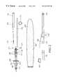
- FIG. 1depicts the preferred embodiment of a device, system and method used to perform on-line cleaning of a fuel-burning facility.
- FIG. 2depicts the device in its disassembled (preassembly) state, and is used to illustrate the method by which this device is assembled for use.
- FIG. 3illustrates the use of the assembled cleaning device to clean an on-line fuel burning or incineration facility.
- FIG. 4depicts an alternative preferred embodiment of this invention, which reduces coolant weight and enhances control over coolant flow, and which utilizes remote detonation.
- FIG. 1depicts the basic tool used for on-line cleaning of a fuel-burning facility such as a boiler, furnace, or similar heat exchange device, or an incineration device, and the discussion following outlines the associated method for such on-line cleaning.
- a fuel-burning facilitysuch as a boiler, furnace, or similar heat exchange device, or an incineration device
- the cleaning of the fuel burning and/or incineration facilityis carried out in the usual manner by means of an explosive device 101 , such as but not limited to an explosive stick or other explosive device or configuration, placed appropriately inside the facility, and then detonated such that the shock waves from the explosion will cause slag and similar deposits to dislodge from the walls, tubing, etc. of the facility.
- This explosive device 101is detonated by a standard explosive cap 102 or similar detonating device, which causes controlled detonation at the desired instant, based on a signal sent from a standard initiator 103 , by a qualified operator.
- a cooling envelope 104which completely envelopes the explosive. During operation, this envelope will have pumped into it a coolant, such as ordinary water, that will maintain the explosive device 101 in a cooled-down state until it is ready for detonation. Because of the direct contact between the coolant and the explosive device 101 , this device is ideally made of a plastic or similar waterproof housing that contains the actual explosive powder or other explosive material.
- This cooling envelope 104is a semi-permeable membrane that allows water to flow out of it at a fairly controlled rate. It can have a series of small perforations punched into it, or can be constructed of any semi-permeable membrane material appropriate to its coolant-delivery function as will outlined herein. This semi-permeability characteristic is illustrated by the series of small dots 105 scattered throughout the envelope 104 as depicted in FIG. 1 .
- the envelope 104is attached to a coolant delivery pipe 106 via an envelope connector 107 .
- the envelope connector 107is cone-shaped apparatus permanently affixed to the coolant delivery pipe 106 , and it further comprises a standard threading 108 .
- the envelope itself, at this open end,is fitted and permanently affixed to complementary threading (not shown) that is easily screwed into and fitted with the threading 108 of the connector 107 . While FIG.
- the coolant delivery pipe 106in the region where said pipe resides within the envelope 104 , further contains a number of coolant delivery apertures 109 , twin ring holders 110 , and an optional butt plate 111 .
- the explosive device 101 with cap 102is affixed to one end of an exposive connector (broomstick) 112 with explosive-to-broomstick attachment means 113 such as duct tape, wire, rope, or any other means that provides a secure attachment.
- the other end of the broomstickis slid through the twin ring holders 110 until it abuts the butt plate 111 , as shown.
- the broomstickmay be further secured by means of, for example, a bolt 114 and wingnut 115 running through both the broomstick 112 and the pipe 106 as depicted. While the rings 110 , butt plate 111 , and nut and bolt 115 and 114 provide one way to secure the broomstick 112 to the pipe 106 , many other ways to secure the broomstick 112 to the pipe 106 can also be devised by someone of ordinary skill, all of which are contemplated within the scope of this disclosure and its related claims.
- the length of the broomstick 112may vary, though for optimum effectiveness, it should maintain the explosive 101 at approximately two or more feet from the end of the pipe 106 that contains the coolant delivery apertures 109 , which, since it is desirable to reuse the pipe 106 and its components, will minimize any possible damage to the pipe 106 and said components when the explosive is detonated, and will also reduce any shock waves sent back down the pipe to the operator of this invention.
- a coolantsuch as water under pressure entering the left side of the pipe 106 as depicted in FIG. 1 will travel through the pipe and exit the pipe through the coolant delivery apertures 109 in a manner illustrated by the directional flow arrows 116 .
- the coolantUpon exiting the pipe 106 through the apertures 109 , the coolant then enters the inside of the envelope 104 and begins to fill up and expand the envelope. As the coolant fills the envelope, it will come into contact with and cool the explosive device 101 .
- the envelope 104is semi-permeable ( 105 )
- waterwill also exit the envelope as the envelope becomes full as shown by the directional arrows 116 a , and so the entry under pressure of new water into the pipe 106 combined with the exit of water through the semipermeable ( 105 ) envelope 104 , will deliver a continuous and stable flow of coolant to the explosive device 101 .
- the entire cooling and cleaning delivery assembly 11 disclosed thus far,is in turn connected to a coolant supply and explosive positioning system 12 as follows.
- a hose 121 with water service(for example, but not limited to, a standard 3/4′′ Chicago firehose and water service) is attached to a hydraulic tube 122 (e.g. pipe) using any suitable hose attachment fitting 123 .
- the coolantpreferable ordinary water, runs under pressure through the hose as indicated by the directional flow arrow 120 .
- the end of the tube 122 opposite the hose 121contains attachment means 124 such as screw threading, which complements and joins with similar threading 117 on the pipe 106 .
- any means known to someone of ordinary skill for joining the tube 122 and pipe 106 in the manner suggested by the arrow 125 in FIG. 1, such that coolant can run from the hose 121 through the tube 122 , into the pipe 106 , and finally into the envelope 104is acceptable and contemplated by this disclosure and its associated claims.
- detonationis achieved by electrically connecting the explosive cap 102 to the initiator 103 .
- Thisis achieved by connecting the initiator 103 to a lead wire pair 126 , in turn connecting to a second lead wire pair 118 , in turn connecting to a cap wire pair 119 .
- This cap wire pair 119is finally connected to the cap 102 .
- the lead wire pair 126enters the tube 122 from the initiator 103 through a lead wire entry port 127 as shown, and then runs through the inside of the tube 122 , and out the far end of the tube.
- This entry port 127can be constructed in any manner obvious to someone of ordinary skill, so long as it enables the wire 126 to enter the tube 122 and averts any significant coolant leakage.)
- the second lead wire pair 118runs through the inside of the pipe 106 , and the cap wire pair 119 is enclosed within the envelope 104 as shown. Thus, when the initiator 103 is activated by the operator, an electrical current flows straight to the cap 102 , detonating the explosive 101 .
- FIG. 1thus depicts electronic detonation of the cap and explosive via a hard wire signal connection
- any alternative means of detonationknown to someone of ordinary skill could also be employed, and is encompassed by this disclosure and its associated claims.
- detonation by a remote control signal connection between the initiator and capwhich will be further discussed in FIG. 4
- eliminating the need for the wires 126 , 118 , and 119is very much an alternative preferred embodiment for detonation.
- non-electronic shocki.e. percussion
- heat-sensitive detonationcan also be used within the spirit and scope of this disclosure and its associated claims.
- the preferred coolantis ordinary water. This is less expensive than any other coolant, it performs the necessary cooling properly, and it is readily available at any site which has a pressurized water supply that may be delivered into this system. Notwithstanding this preference for ordinary water as the coolant, this disclosure contemplates that many other coolants known to someone of ordinary skill can also be used for this purpose as well, and all such coolants are regarded to be within the scope of the claims.
- FIG. 2shows the preferred embodiment of FIG. 1 in preassembly state, disassembled into its primary components.
- the explosive 101is attached to the cap 102 , with the cap in turn connected to the one end of the cap wire pair 119 .
- This assemblyis attached to one end of the broomstick 112 using the explosive-to-broomstick attachment means 113 such as duct tape, wire, rope, etc., or any other approach known to someone of ordinary skill, as earlier depicted in FIG. 1 .
- the other end of the broomstick 112is slid into the twin ring holders 110 of the pipe 106 until it abuts the butt plate 111 , also as earlier shown in FIG. 1 .
- the bolt 114 and nut 115may be used to further secure the broomstick 112 to the pipe 106 .
- the second lead wire pair 118is attached to the remaining end of the cap wire pair 119 to provide an electrical connection therebetween.
- the right-hand side (in FIG. 2) of lead wire pair 126is attached to the remaining end of the second lead wire pair 118 providing an electrical connection therebetween.
- the pipe 106is then attached to one end of the hydraulic tube 122 as also discussed in connection with FIG. 1, and the hose 121 is hooked to the other end of the tube 122 , completing all coolant delivery connections.
- the initiator 103is attached to the remaining end of the lead wire pair 126 forming an electrical connection therebetween, and completing the electrical connection from the initiator 103 to the cap 102 .
- the on-line cleaning deviceis fully assembled into the configuration shown in FIG. 1 .
- FIG. 3now depicts the usage of this fully assembled on-line cleaning device, to clean a fuel burning facility 31 such as a boiler, furnace, scrubber, incinerator, etc., and indeed any fuel-burning or refuse-burning device for which cleaning by explosives is suitable.
- a fuel burning facility 31such as a boiler, furnace, scrubber, incinerator, etc.
- any fuel-burning or refuse-burning device for which cleaning by explosivesis suitable.
- the entire cooling and cleaning delivery assembly 11is placed into the on-line facility 31 through an entry port 32 such as a manway, handway, portal, or other similar means of entry, while the coolant supply and explosive positioning system 12 remains outside of said facility.
- an entry port 32such as a manway, handway, portal, or other similar means of entry
- the pipe 106 or tube 122is rested against the bottom of the entry port 32 at the point designated by 33 . Because the coolant pumped through the envelope 104 introduces a fair amount of weight into assembly 11 (with some weight also added to the system 12 ), a downward force designated by 34 is exerted to the system 12 , with the point 33 acting as the fulcrum.
- the operatorpositions the explosive 101 to the position desired. It is further possible to place a fulcrum fitting device (not shown) at location 33 , so as to provide a stable fulcrum and also protect the bottom of the port 32 from the significant weight pressure that will be exerted at the fulcrum.
- a fulcrum fitting device(not shown) at location 33 , so as to provide a stable fulcrum and also protect the bottom of the port 32 from the significant weight pressure that will be exerted at the fulcrum.
- new (cooler) coolantis constantly flowing into the system while older (hotter) coolant which has been heated by the on-line facility exits via the semipermeable envelope 104 , so that this continued flow of coolant into the system maintains the explosive 101 in a cool state.
- the initiator 103is activated to initiate the explosion. This explosion creates a shock wave in region 35 , which thereby cleans and deslags that region of the boiler or similar facility, while the boiler/facility is still hot
- the explosive 101 , cap 102 , cap wire 119 , broomstick 112 , and broomstick attachment means 113are all destroyed by the explosion, as is the envelope 104 .
- the envelope 104which is for a single use only, should be fabricated from a material that is inexpensive, yet durable enough to maintain physical integrity while water is being pumped into it under pressure.
- this envelope 104must be semipermeable ( 105 ), which can be achieved, for example, by using any appropriate membrane which in essence acts as a filter, either with a limited number of macroscopic puncture holes, or a large number of fine, microscopic holes.
- all other componentsparticularly the pipe 106 and all of its components 107 , 108 , 109 , 110 , 111 , and 118 , as well as the bolt 114 and nut 115 , are reusable, and so should be designed from materials that provide proper durability in the vicinity of the explosion.
- the length of the broomstick 112determines the distance of the pipe 106 and its said components from the explosion, and that approximately two feet or more is a desirable distance to impose between the explosive 101 and any said component of the pipe 106 .
- coolant filling the envelope 104adds significant weight to the right of the fulcrum 33 in FIG. 3, the materials used to construct the cleaning delivery assembly 11 should be as lightweight as possible so long as they can endure both the heat of the furnace and the explosion (the envelope 104 should be as light as possible yet resistant to any possible heat damage), while to counterbalance the weight of 11 , the coolant supply and explosive positioning system 12 may be constructed of heavier materials, and may optionally include added weight simply for ballast. Water weight can also be counterbalanced by lengthening the system 12 so that force 34 can be applied farther from the fulcrum 33 .
- system 12is shown here as embodying a single tube 122 , it is obvious that this assembly can also be designed to employ a plurality of tubes attached to one another, and can also be designed so as to telescope from a shorter tube into a longer tube. All such variations, and others that may be obvious to someone of ordinary skill, are fully contemplated by this disclosure and included within the scope of its associated claims.
- FIG. 4depicts an alternative preferred embodiment of this invention with reduced coolant weight and enhanced control over coolant flow, and remote detonation.
- the cap 102now detonates the explosive 101 by a remote control, wireless signal connection 401 sent from the initiator 103 to the cap 102 .
- FIG. 4further shows a modified envelope 104 ′, which is narrower where the coolant first enters from the pipe 106 and wider in the region 402 of the explosive 101 . Additionally, this envelope is impermeable in the region where coolant first enters the pipe, and permeable ( 105 ) only in the region near the explosive 101 . This modification achieves two results.
- a main object of this inventionis to cool the explosive 101 so that it can be introduced into an on-line fuel-burning facility, it is desirable to make the region of the envelope 104 ′ where the explosive is not present as narrow as possible, thus reducing the water weight in this region and making it easier to achieve a proper weight balance about the fulcrum, as discussed in connection with FIG. 3 .
- a greater volume of coolantwill reside in precisely the area that it is needed to cool the explosive 101 , thus enhancing cooling efficiency.
- the impermeability of the entry region and midsection of the envelope 104 ′will enable all newly-introduced coolant to reach the explosive before that coolant is allowed to exit the envelope 104 ′ from its permeable ( 105 ) section 402 .
- the coolant in the permeable region of the envelopewill typically have been in the envelope longest, and will therefore be the hottest.
- the hotter coolant leaving the systemis precisely the coolant that should be leaving, while the cooler coolant cannot exit the system until it has travelled through the entire system and thus become hotter and therefore ready to leave.
Landscapes
- Engineering & Computer Science (AREA)
- Mechanical Engineering (AREA)
- General Engineering & Computer Science (AREA)
- Chemical & Material Sciences (AREA)
- Combustion & Propulsion (AREA)
- Physics & Mathematics (AREA)
- Thermal Sciences (AREA)
- Heat-Exchange Devices With Radiators And Conduit Assemblies (AREA)
- Cleaning In General (AREA)
- Cleaning By Liquid Or Steam (AREA)
Abstract
Description
Claims (18)
Priority Applications (7)
| Application Number | Priority Date | Filing Date | Title |
|---|---|---|---|
| US09/341,395US6431073B1 (en) | 1998-01-14 | 1998-01-14 | Device, system and method for on-line explosive deslagging |
| US09/769,845US20010007247A1 (en) | 1997-01-17 | 2001-01-25 | Device, system and method for on-line explosive deslagging |
| US10/063,533US6644201B2 (en) | 1997-01-17 | 2002-05-02 | Device, system and method for on-line explosive deslagging |
| US10/064,730US6604468B2 (en) | 1997-01-17 | 2002-08-12 | Device, system and method for on-line explosive deslagging |
| US10/604,631US20040107858A1 (en) | 1997-01-17 | 2003-08-06 | Device, System and Method for On-Line Explosive Deslagging |
| US10/710,209US20040216698A1 (en) | 1997-01-17 | 2004-06-25 | Device, system and method for on-line explosive deslagging |
| US11/162,334US7395760B2 (en) | 1997-01-17 | 2005-09-07 | Device, system and method for on-line explosive deslagging |
Applications Claiming Priority (2)
| Application Number | Priority Date | Filing Date | Title |
|---|---|---|---|
| US09/341,395US6431073B1 (en) | 1998-01-14 | 1998-01-14 | Device, system and method for on-line explosive deslagging |
| PCT/US1998/000718WO1998031975A1 (en) | 1997-01-17 | 1998-01-14 | Device, system and method for on-line explosive deslagging |
Related Parent Applications (5)
| Application Number | Title | Priority Date | Filing Date |
|---|---|---|---|
| US08/786,096ContinuationUS5769034A (en) | 1997-01-17 | 1997-01-17 | Device, system and method for on-line explosive deslagging |
| US08/786,096A-371-Of-InternationalUS5769034A (en) | 1997-01-17 | 1997-01-17 | Device, system and method for on-line explosive deslagging |
| PCT/US1998/000718A-371-Of-InternationalWO1998031975A1 (en) | 1997-01-17 | 1998-01-14 | Device, system and method for on-line explosive deslagging |
| PCT/US1998/000718ContinuationWO1998031975A1 (en) | 1997-01-17 | 1998-01-14 | Device, system and method for on-line explosive deslagging |
| US08786096Continuation | 1998-01-14 |
Related Child Applications (2)
| Application Number | Title | Priority Date | Filing Date |
|---|---|---|---|
| US09/394,377Continuation-In-PartUS6321690B1 (en) | 1997-01-17 | 1999-09-10 | Device, system and method for on-line explosive deslagging |
| US10/064,730ContinuationUS6604468B2 (en) | 1997-01-17 | 2002-08-12 | Device, system and method for on-line explosive deslagging |
Publications (1)
| Publication Number | Publication Date |
|---|---|
| US6431073B1true US6431073B1 (en) | 2002-08-13 |
Family
ID=23337367
Family Applications (4)
| Application Number | Title | Priority Date | Filing Date |
|---|---|---|---|
| US09/341,395Expired - LifetimeUS6431073B1 (en) | 1997-01-17 | 1998-01-14 | Device, system and method for on-line explosive deslagging |
| US10/064,730Expired - LifetimeUS6604468B2 (en) | 1997-01-17 | 2002-08-12 | Device, system and method for on-line explosive deslagging |
| US10/604,631AbandonedUS20040107858A1 (en) | 1997-01-17 | 2003-08-06 | Device, System and Method for On-Line Explosive Deslagging |
| US11/162,334Expired - Fee RelatedUS7395760B2 (en) | 1997-01-17 | 2005-09-07 | Device, system and method for on-line explosive deslagging |
Family Applications After (3)
| Application Number | Title | Priority Date | Filing Date |
|---|---|---|---|
| US10/064,730Expired - LifetimeUS6604468B2 (en) | 1997-01-17 | 2002-08-12 | Device, system and method for on-line explosive deslagging |
| US10/604,631AbandonedUS20040107858A1 (en) | 1997-01-17 | 2003-08-06 | Device, System and Method for On-Line Explosive Deslagging |
| US11/162,334Expired - Fee RelatedUS7395760B2 (en) | 1997-01-17 | 2005-09-07 | Device, system and method for on-line explosive deslagging |
Country Status (1)
| Country | Link |
|---|---|
| US (4) | US6431073B1 (en) |
Cited By (16)
| Publication number | Priority date | Publication date | Assignee | Title |
|---|---|---|---|---|
| US6530325B2 (en)* | 2001-07-11 | 2003-03-11 | Shapiro Brothers, Inc. | Method of scrapping steel structures |
| US6604468B2 (en)* | 1997-01-17 | 2003-08-12 | North American Industrial Services, Inc. | Device, system and method for on-line explosive deslagging |
| US6644201B2 (en) | 1997-01-17 | 2003-11-11 | Northamerican Industrial Services, Inc. | Device, system and method for on-line explosive deslagging |
| US20040112306A1 (en)* | 2001-04-12 | 2004-06-17 | Hans Ruegg | Method for cleaning combustion devices |
| US6755156B1 (en)* | 1999-09-13 | 2004-06-29 | Northamerican Industrial Services, Inc. | Device, system and method for on-line explosive deslagging |
| US20050125931A1 (en)* | 2003-12-11 | 2005-06-16 | Chenevert Blake C. | Detonative cleaning apparatus |
| US20060272684A1 (en)* | 2005-06-01 | 2006-12-07 | Steur Frans Jr | Method of and apparatus for cleaning fouling in heat exchangers, waste-heat boilers and combustion chamgers |
| US20150343501A1 (en)* | 2012-12-20 | 2015-12-03 | Bang & Clean Gmbh | Device and method for cleaning combustion devices |
| US9541282B2 (en) | 2014-03-10 | 2017-01-10 | International Paper Company | Boiler system controlling fuel to a furnace based on temperature of a structure in a superheater section |
| US9671183B2 (en) | 2007-12-17 | 2017-06-06 | International Paper Company | Controlling cooling flow in a sootblower based on lance tube temperature |
| US9915589B2 (en) | 2014-07-25 | 2018-03-13 | International Paper Company | System and method for determining a location of fouling on boiler heat transfer surface |
| US9927231B2 (en)* | 2014-07-25 | 2018-03-27 | Integrated Test & Measurement (ITM), LLC | System and methods for detecting, monitoring, and removing deposits on boiler heat exchanger surfaces using vibrational analysis |
| US10060688B2 (en) | 2014-07-25 | 2018-08-28 | Integrated Test & Measurement (ITM) | System and methods for detecting, monitoring, and removing deposits on boiler heat exchanger surfaces using vibrational analysis |
| JP2021032422A (en)* | 2019-08-16 | 2021-03-01 | 三菱パワー株式会社 | Cleaning method inside the piping, piping structure and boiler |
| CN113122665A (en)* | 2021-04-16 | 2021-07-16 | 广东韶钢松山股份有限公司 | Method for treating dead iron layer of hearth after blast furnace shutdown |
| US12345410B2 (en) | 2020-05-01 | 2025-07-01 | International Paper Company | System and methods for controlling operation of a recovery boiler to reduce fouling |
Families Citing this family (6)
| Publication number | Priority date | Publication date | Assignee | Title |
|---|---|---|---|---|
| US7360508B2 (en)* | 2004-06-14 | 2008-04-22 | Diamond Power International, Inc. | Detonation / deflagration sootblower |
| US20080271685A1 (en) | 2007-05-04 | 2008-11-06 | Lupkes Kirk R | Detonative cleaning apparatus |
| US20090277479A1 (en)* | 2008-05-09 | 2009-11-12 | Lupkes Kirk R | Detonative Cleaning Apparatus |
| US20110139185A1 (en)* | 2009-12-16 | 2011-06-16 | General Electric Company | Systems and Methods for Phasing Multiple Impulse Cleaning Devices |
| CA2932398C (en) | 2013-12-02 | 2019-03-05 | Austin Star Detonator Company | Method and apparatus for wireless blasting |
| US9751090B2 (en)* | 2015-06-01 | 2017-09-05 | US Nitro Blasting & Environmental, LLC | Methods for cleaning precipitators |
Citations (26)
| Publication number | Priority date | Publication date | Assignee | Title |
|---|---|---|---|---|
| BE538867A (en) | ||||
| US2840365A (en) | 1954-06-11 | 1958-06-24 | Springit Nv | Method of breaking formation of solid deposits |
| GB823353A (en) | 1956-09-07 | 1959-11-11 | Du Pont | Improvements in or relating to the purging of electric furnaces |
| LU41977A1 (en) | 1962-06-30 | 1962-08-30 | ||
| US3053525A (en) | 1957-09-30 | 1962-09-11 | Siderurgie Fse Inst Rech | Porous refractory concrete element |
| US3552259A (en) | 1968-07-19 | 1971-01-05 | Commerican Solvents Corp | Process and apparatus for preparing detonating and deflagrating fuse and product |
| AU2082270A (en) | 1970-10-07 | 1972-04-13 | Monzino Riotinto Of Australia Limited | Cooling of lances |
| US4166418A (en) | 1977-05-23 | 1979-09-04 | Austin Powder Company | Time delay primer and method of making same |
| US4167139A (en) | 1977-05-23 | 1979-09-11 | Austin Powder Company | Time delay primer and method of using same |
| US4354294A (en) | 1980-09-10 | 1982-10-19 | White Consolidated Industries, Inc. | Rotary wall deslagger |
| US4462319A (en) | 1982-10-27 | 1984-07-31 | Detector Electronics Corp. | Method and apparatus for safely controlling explosions in black liquor recovery boilers |
| US4545411A (en) | 1983-09-19 | 1985-10-08 | Nalco Chemical Company | Method and apparatus for reducing boiler sootblowing requirements |
| FR2567426A1 (en) | 1984-07-13 | 1986-01-17 | Maurel Robert | Method for the removal of solid residues deposited on walls by the use of a detonating fuse |
| US4639381A (en) | 1983-09-19 | 1987-01-27 | Nalco Chemical Company | Method for reducing fireside tube deposition and boiler sootblowing requirements |
| US5056587A (en) | 1990-09-07 | 1991-10-15 | Halliburton Company | Method for deslagging a boiler |
| US5113802A (en) | 1991-03-26 | 1992-05-19 | Union Camp Corporation | Method and apparatus for removing deposit from recovery boilers |
| US5193491A (en) | 1991-04-01 | 1993-03-16 | Delaware Capital Formation, Inc. | Cleaning system for boiler |
| US5196698A (en)* | 1991-11-01 | 1993-03-23 | Baker Hughes Corporation | Method and apparatus for nuclear logging using lithium detector assemblies |
| US5196648A (en) | 1991-05-30 | 1993-03-23 | Jet Research Center, Inc. | Method for deslagging a cyclone furnace |
| US5211135A (en) | 1992-04-23 | 1993-05-18 | Correia Paul A | Apparatus and method of deslagging a boiler with an explosive blastwave and kinetic energy |
| JPH06147775A (en) | 1991-12-13 | 1994-05-27 | Nippon Steel Corp | Method for partial cooling of high-temperature and large-sized steel structure |
| JPH06313532A (en) | 1993-04-30 | 1994-11-08 | Shinagawa Refract Co Ltd | Structure of side wall of incinerating furnace and brick for side wall of incinerating furnace |
| US5494004A (en) | 1994-09-23 | 1996-02-27 | Lockheed Corporation | On line pulsed detonation/deflagration soot blower |
| US5517950A (en) | 1993-05-26 | 1996-05-21 | Kendrick; William E. | System for slag removal and the like |
| US5665933A (en)* | 1992-03-11 | 1997-09-09 | B Omentum Leasing Ab | Device for cladding tubes by means of an explosive process |
| US5769034A (en) | 1997-01-17 | 1998-06-23 | Zilka; Frank | Device, system and method for on-line explosive deslagging |
Family Cites Families (9)
| Publication number | Priority date | Publication date | Assignee | Title |
|---|---|---|---|---|
| JPS5334700B2 (en) | 1972-06-22 | 1978-09-21 | ||
| US4756248A (en) | 1987-09-28 | 1988-07-12 | Morton Thiokol, Inc. | Low mass grain support system for solid propellant rocket motors |
| JP2951390B2 (en) | 1990-10-19 | 1999-09-20 | 株式会社カコー | Water-cooled explosion tube |
| JP2787177B2 (en) | 1992-04-30 | 1998-08-13 | 新日本製鐵株式会社 | Explosive loading bag in blasting equipment |
| US6321690B1 (en)* | 1997-01-17 | 2001-11-27 | North American Industrial Services, Inc. | Device, system and method for on-line explosive deslagging |
| US6431073B1 (en)* | 1998-01-14 | 2002-08-13 | North American Industrial Services, Inc. | Device, system and method for on-line explosive deslagging |
| JPH10253059A (en) | 1997-03-11 | 1998-09-25 | Nikko Co | Method for manufacturing circuit board for explosive ignition heating tool |
| NO307717B1 (en)* | 1997-09-12 | 2000-05-15 | Dyno Ind Asa | Method of charging and sensitizing a slurry explosive in a borehole |
| DE50201779D1 (en) | 2001-04-12 | 2005-01-20 | Bang & Clean Gmbh Wohlen | METHOD AND DEVICE FOR CLEANING COMBUSTION FACILITIES |
- 1998
- 1998-01-14USUS09/341,395patent/US6431073B1/ennot_activeExpired - Lifetime
- 2002
- 2002-08-12USUS10/064,730patent/US6604468B2/ennot_activeExpired - Lifetime
- 2003
- 2003-08-06USUS10/604,631patent/US20040107858A1/ennot_activeAbandoned
- 2005
- 2005-09-07USUS11/162,334patent/US7395760B2/ennot_activeExpired - Fee Related
Patent Citations (28)
| Publication number | Priority date | Publication date | Assignee | Title |
|---|---|---|---|---|
| BE538867A (en) | ||||
| US2840365A (en) | 1954-06-11 | 1958-06-24 | Springit Nv | Method of breaking formation of solid deposits |
| GB823353A (en) | 1956-09-07 | 1959-11-11 | Du Pont | Improvements in or relating to the purging of electric furnaces |
| US3053525A (en) | 1957-09-30 | 1962-09-11 | Siderurgie Fse Inst Rech | Porous refractory concrete element |
| LU41977A1 (en) | 1962-06-30 | 1962-08-30 | ||
| US3552259A (en) | 1968-07-19 | 1971-01-05 | Commerican Solvents Corp | Process and apparatus for preparing detonating and deflagrating fuse and product |
| AU2082270A (en) | 1970-10-07 | 1972-04-13 | Monzino Riotinto Of Australia Limited | Cooling of lances |
| US4166418A (en) | 1977-05-23 | 1979-09-04 | Austin Powder Company | Time delay primer and method of making same |
| US4167139A (en) | 1977-05-23 | 1979-09-11 | Austin Powder Company | Time delay primer and method of using same |
| US4354294A (en) | 1980-09-10 | 1982-10-19 | White Consolidated Industries, Inc. | Rotary wall deslagger |
| US4462319A (en) | 1982-10-27 | 1984-07-31 | Detector Electronics Corp. | Method and apparatus for safely controlling explosions in black liquor recovery boilers |
| US4545411A (en) | 1983-09-19 | 1985-10-08 | Nalco Chemical Company | Method and apparatus for reducing boiler sootblowing requirements |
| US4639381A (en) | 1983-09-19 | 1987-01-27 | Nalco Chemical Company | Method for reducing fireside tube deposition and boiler sootblowing requirements |
| FR2567426A1 (en) | 1984-07-13 | 1986-01-17 | Maurel Robert | Method for the removal of solid residues deposited on walls by the use of a detonating fuse |
| US5056587A (en) | 1990-09-07 | 1991-10-15 | Halliburton Company | Method for deslagging a boiler |
| US5113802A (en) | 1991-03-26 | 1992-05-19 | Union Camp Corporation | Method and apparatus for removing deposit from recovery boilers |
| US5279676A (en) | 1991-04-01 | 1994-01-18 | Delaware Capital Formation, Inc. | Method for cleaning a boiler |
| US5193491A (en) | 1991-04-01 | 1993-03-16 | Delaware Capital Formation, Inc. | Cleaning system for boiler |
| US5307743A (en) | 1991-05-30 | 1994-05-03 | Halliburton Company | Apparatus for deslagging a cyclone furnace |
| US5196648A (en) | 1991-05-30 | 1993-03-23 | Jet Research Center, Inc. | Method for deslagging a cyclone furnace |
| US5196698A (en)* | 1991-11-01 | 1993-03-23 | Baker Hughes Corporation | Method and apparatus for nuclear logging using lithium detector assemblies |
| JPH06147775A (en) | 1991-12-13 | 1994-05-27 | Nippon Steel Corp | Method for partial cooling of high-temperature and large-sized steel structure |
| US5665933A (en)* | 1992-03-11 | 1997-09-09 | B Omentum Leasing Ab | Device for cladding tubes by means of an explosive process |
| US5211135A (en) | 1992-04-23 | 1993-05-18 | Correia Paul A | Apparatus and method of deslagging a boiler with an explosive blastwave and kinetic energy |
| JPH06313532A (en) | 1993-04-30 | 1994-11-08 | Shinagawa Refract Co Ltd | Structure of side wall of incinerating furnace and brick for side wall of incinerating furnace |
| US5517950A (en) | 1993-05-26 | 1996-05-21 | Kendrick; William E. | System for slag removal and the like |
| US5494004A (en) | 1994-09-23 | 1996-02-27 | Lockheed Corporation | On line pulsed detonation/deflagration soot blower |
| US5769034A (en) | 1997-01-17 | 1998-06-23 | Zilka; Frank | Device, system and method for on-line explosive deslagging |
Non-Patent Citations (6)
| Title |
|---|
| Database WPI, Section Ch, Week 9426, Derwent Publications Ltd., London, GB; Class M24, AN 94-211580, XP002061357 & JP 06 147 775 (Nippon Steel Corp.), May 27, 1994. |
| Database WPI, Section Ch, Week 9504, Derwent Publications Ltd., London, GB; Class J09, AN 95-027953, XP002061356 & JP 06 313 532 (Shingawaw Fire Brick), Nov. 8, 1994. |
| English-language translation of Cite No. 1. |
| English-language translation of Cite No. 3. |
| Jendersie, H.: Untersuchungen zum Konturenspregen beim untertagigen Abau. Neue Bergbautechnik 3 (1973) H. 3 (Cited as footnote 18 in Cite No. 1). |
| VBB publication No. 541 070 8 (GDR, 1980), pp. 344-352 & 407. |
Cited By (28)
| Publication number | Priority date | Publication date | Assignee | Title |
|---|---|---|---|---|
| US6604468B2 (en)* | 1997-01-17 | 2003-08-12 | North American Industrial Services, Inc. | Device, system and method for on-line explosive deslagging |
| US6644201B2 (en) | 1997-01-17 | 2003-11-11 | Northamerican Industrial Services, Inc. | Device, system and method for on-line explosive deslagging |
| US20040107858A1 (en)* | 1997-01-17 | 2004-06-10 | Northamerican Industrial Services, Inc. | Device, System and Method for On-Line Explosive Deslagging |
| US20040216698A1 (en)* | 1997-01-17 | 2004-11-04 | Northamerican Industrial Services | Device, system and method for on-line explosive deslagging |
| US20060027191A1 (en)* | 1997-01-17 | 2006-02-09 | Northamerican Industrial Services, Inc. | Device, System and Method for On-Line Explosive Deslagging |
| US7395760B2 (en) | 1997-01-17 | 2008-07-08 | Northamerican Industrial Services, Inc. | Device, system and method for on-line explosive deslagging |
| US6755156B1 (en)* | 1999-09-13 | 2004-06-29 | Northamerican Industrial Services, Inc. | Device, system and method for on-line explosive deslagging |
| US20040112306A1 (en)* | 2001-04-12 | 2004-06-17 | Hans Ruegg | Method for cleaning combustion devices |
| US6935281B2 (en)* | 2001-04-12 | 2005-08-30 | Bang & Clean Gmbh | Method for cleaning combustion devices |
| US6530325B2 (en)* | 2001-07-11 | 2003-03-11 | Shapiro Brothers, Inc. | Method of scrapping steel structures |
| US7442034B2 (en)* | 2003-12-11 | 2008-10-28 | Shocksystem, Inc. | Detonative cleaning apparatus |
| US20050125931A1 (en)* | 2003-12-11 | 2005-06-16 | Chenevert Blake C. | Detonative cleaning apparatus |
| US7959432B2 (en)* | 2005-06-01 | 2011-06-14 | Frans Steur, Senior | Method of and apparatus for cleaning fouling in heat exchangers, waste-heat boilers and combustion chambers |
| US20110114035A1 (en)* | 2005-06-01 | 2011-05-19 | Steur Jr Frans | Method of and apparatus for cleaning fouling in heat exchangers, waste-heat boilers and combustion chambers |
| US20060272684A1 (en)* | 2005-06-01 | 2006-12-07 | Steur Frans Jr | Method of and apparatus for cleaning fouling in heat exchangers, waste-heat boilers and combustion chamgers |
| US9671183B2 (en) | 2007-12-17 | 2017-06-06 | International Paper Company | Controlling cooling flow in a sootblower based on lance tube temperature |
| US20150343501A1 (en)* | 2012-12-20 | 2015-12-03 | Bang & Clean Gmbh | Device and method for cleaning combustion devices |
| US9636717B2 (en)* | 2012-12-20 | 2017-05-02 | Bang & Clean Gmbh | Device and method for cleaning combustion devices |
| US9541282B2 (en) | 2014-03-10 | 2017-01-10 | International Paper Company | Boiler system controlling fuel to a furnace based on temperature of a structure in a superheater section |
| US9915589B2 (en) | 2014-07-25 | 2018-03-13 | International Paper Company | System and method for determining a location of fouling on boiler heat transfer surface |
| US9927231B2 (en)* | 2014-07-25 | 2018-03-27 | Integrated Test & Measurement (ITM), LLC | System and methods for detecting, monitoring, and removing deposits on boiler heat exchanger surfaces using vibrational analysis |
| US20180195860A1 (en)* | 2014-07-25 | 2018-07-12 | Integrated Test & Measurement (ITM), LLC | System and methods for detecting, monitoring, and removing deposits on boiler heat exchanger surfaces using vibrational analysis |
| US10060688B2 (en) | 2014-07-25 | 2018-08-28 | Integrated Test & Measurement (ITM) | System and methods for detecting, monitoring, and removing deposits on boiler heat exchanger surfaces using vibrational analysis |
| US10094660B2 (en)* | 2014-07-25 | 2018-10-09 | Integrated Test & Measurement (ITM), LLC | System and methods for detecting, monitoring, and removing deposits on boiler heat exchanger surfaces using vibrational analysis |
| US10724858B2 (en)* | 2014-07-25 | 2020-07-28 | Integrated Test & Measurement (ITM), LLC | System and methods for detecting, monitoring, and removing deposits on boiler heat exchanger surfaces using vibrational analysis |
| JP2021032422A (en)* | 2019-08-16 | 2021-03-01 | 三菱パワー株式会社 | Cleaning method inside the piping, piping structure and boiler |
| US12345410B2 (en) | 2020-05-01 | 2025-07-01 | International Paper Company | System and methods for controlling operation of a recovery boiler to reduce fouling |
| CN113122665A (en)* | 2021-04-16 | 2021-07-16 | 广东韶钢松山股份有限公司 | Method for treating dead iron layer of hearth after blast furnace shutdown |
Also Published As
| Publication number | Publication date |
|---|---|
| US20060027191A1 (en) | 2006-02-09 |
| US20040107858A1 (en) | 2004-06-10 |
| US20020178957A1 (en) | 2002-12-05 |
| US6604468B2 (en) | 2003-08-12 |
| US7395760B2 (en) | 2008-07-08 |
Similar Documents
| Publication | Publication Date | Title |
|---|---|---|
| EP0974035B1 (en) | Device, system and method for on-line explosive deslagging | |
| US6431073B1 (en) | Device, system and method for on-line explosive deslagging | |
| US6321690B1 (en) | Device, system and method for on-line explosive deslagging | |
| US6755156B1 (en) | Device, system and method for on-line explosive deslagging | |
| HK1025146B (en) | Device, system and method for on-line explosive deslagging | |
| MXPA99006728A (en) | Device, system and method for on-line explosive deslagging | |
| CH694381A5 (en) | Explosion based cleaning system for hot installations, e.g. ovens or boilers, includes cooling device for the explosion device to allow cleaning during installation operation |
Legal Events
| Date | Code | Title | Description |
|---|---|---|---|
| AS | Assignment | Owner name:NORTH AMERICAN INDUSTRIAL SERVICES, INC., NEW YORK Free format text:ASSIGNMENT OF ASSIGNORS INTEREST;ASSIGNORS:ZILKA, FRANCIS;ZILKA, TIMOTHY;PROUTY, KURT;AND OTHERS;REEL/FRAME:010146/0416 Effective date:19990526 | |
| STCF | Information on status: patent grant | Free format text:PATENTED CASE | |
| FPAY | Fee payment | Year of fee payment:4 | |
| FPAY | Fee payment | Year of fee payment:8 | |
| AS | Assignment | Owner name:FIRST NIAGARA BANK, N.A. AS AGENT, NEW YORK Free format text:SECURITY INTEREST;ASSIGNOR:NORTH AMERICAN INDUSTRIAL SERVICES, INC.;REEL/FRAME:027611/0674 Effective date:20111019 | |
| FPAY | Fee payment | Year of fee payment:12 | |
| AS | Assignment | Owner name:NORTH AMERICAN INDUSTRIAL SERVICES, INC., NEW YORK Free format text:TERMINATION AND RELEASE OF PATENT SECURITY AGREEMENT AT REEL/FRAME NO. 27611/0674;ASSIGNOR:FIRST NIAGARA BANK, N.A.;REEL/FRAME:039070/0265 Effective date:20160617 Owner name:BNP PARIBAS, AS ADMINISTRATIVE AGENT, NEW YORK Free format text:GRANT OF PATENT SECURITY INTEREST;ASSIGNOR:NORTH AMERICAN INDUSTRIAL SERVICES, INC.;REEL/FRAME:039139/0565 Effective date:20160617 | |
| AS | Assignment | Owner name:NORTH AMERICAN INDUSTRIAL SERVICES, INC., NEW YORK Free format text:RELEASE BY SECURED PARTY;ASSIGNOR:FIRST NIAGARA BANK, N.A. AS AGENT;REEL/FRAME:038976/0012 Effective date:20160617 | |
| AS | Assignment | Owner name:NORTH AMERICAN INDUSTRIAL SERVICES, INC., TEXAS Free format text:RELEASE OF PATENT SECURITY INTEREST;ASSIGNOR:BNP PARIBAS, AS ADMINISTRATIVE AGENT;REEL/FRAME:057318/0954 Effective date:20210813 |