US6430125B1 - Methods and apparatus for detecting and correcting magnification error in a multi-beam optical disk drive - Google Patents
Methods and apparatus for detecting and correcting magnification error in a multi-beam optical disk driveDownload PDFInfo
- Publication number
- US6430125B1 US6430125B1US09/037,471US3747198AUS6430125B1US 6430125 B1US6430125 B1US 6430125B1US 3747198 AUS3747198 AUS 3747198AUS 6430125 B1US6430125 B1US 6430125B1
- Authority
- US
- United States
- Prior art keywords
- optical
- optical disk
- magnification error
- writing
- magnification
- Prior art date
- Legal status (The legal status is an assumption and is not a legal conclusion. Google has not performed a legal analysis and makes no representation as to the accuracy of the status listed.)
- Expired - Lifetime
Links
- 230000003287optical effectEffects0.000titleclaimsabstractdescription229
- 238000000034methodMethods0.000titleclaimsabstractdescription48
- 239000000758substrateSubstances0.000claimsdescription9
- 230000002596correlated effectEffects0.000claimsdescription7
- 230000000875corresponding effectEffects0.000claimsdescription7
- 238000012937correctionMethods0.000description15
- 238000005516engineering processMethods0.000description6
- 238000013461designMethods0.000description5
- 238000001514detection methodMethods0.000description4
- 230000007246mechanismEffects0.000description4
- 238000002310reflectometryMethods0.000description4
- 238000003860storageMethods0.000description4
- 230000000694effectsEffects0.000description3
- 238000004519manufacturing processMethods0.000description3
- 238000004458analytical methodMethods0.000description2
- 230000008859changeEffects0.000description2
- 238000009826distributionMethods0.000description2
- 238000005286illuminationMethods0.000description2
- 238000003384imaging methodMethods0.000description2
- 239000000463materialSubstances0.000description2
- 229920000642polymerPolymers0.000description2
- 230000008569processEffects0.000description2
- 230000004044responseEffects0.000description2
- 238000012546transferMethods0.000description2
- 238000013459approachMethods0.000description1
- 201000009310astigmatismDiseases0.000description1
- 238000013500data storageMethods0.000description1
- 230000001419dependent effectEffects0.000description1
- 238000010586diagramMethods0.000description1
- PCHJSUWPFVWCPO-UHFFFAOYSA-NgoldChemical compound[Au]PCHJSUWPFVWCPO-UHFFFAOYSA-N0.000description1
- 239000010931goldSubstances0.000description1
- 229910052737goldInorganic materials0.000description1
- 230000014759maintenance of locationEffects0.000description1
- 229920000620organic polymerPolymers0.000description1
- 239000000126substanceSubstances0.000description1
- 125000000391vinyl groupChemical group[H]C([*])=C([H])[H]0.000description1
- 229920002554vinyl polymerPolymers0.000description1
Images


Classifications
- G—PHYSICS
- G11—INFORMATION STORAGE
- G11B—INFORMATION STORAGE BASED ON RELATIVE MOVEMENT BETWEEN RECORD CARRIER AND TRANSDUCER
- G11B7/00—Recording or reproducing by optical means, e.g. recording using a thermal beam of optical radiation by modifying optical properties or the physical structure, reproducing using an optical beam at lower power by sensing optical properties; Record carriers therefor
- G11B7/12—Heads, e.g. forming of the optical beam spot or modulation of the optical beam
- G11B7/135—Means for guiding the beam from the source to the record carrier or from the record carrier to the detector
- G11B7/1398—Means for shaping the cross-section of the beam, e.g. into circular or elliptical cross-section
- G—PHYSICS
- G11—INFORMATION STORAGE
- G11B—INFORMATION STORAGE BASED ON RELATIVE MOVEMENT BETWEEN RECORD CARRIER AND TRANSDUCER
- G11B7/00—Recording or reproducing by optical means, e.g. recording using a thermal beam of optical radiation by modifying optical properties or the physical structure, reproducing using an optical beam at lower power by sensing optical properties; Record carriers therefor
- G11B7/08—Disposition or mounting of heads or light sources relatively to record carriers
- G11B7/09—Disposition or mounting of heads or light sources relatively to record carriers with provision for moving the light beam or focus plane for the purpose of maintaining alignment of the light beam relative to the record carrier during transducing operation, e.g. to compensate for surface irregularities of the latter or for track following
- G11B7/0943—Methods and circuits for performing mathematical operations on individual detector segment outputs
- G—PHYSICS
- G11—INFORMATION STORAGE
- G11B—INFORMATION STORAGE BASED ON RELATIVE MOVEMENT BETWEEN RECORD CARRIER AND TRANSDUCER
- G11B7/00—Recording or reproducing by optical means, e.g. recording using a thermal beam of optical radiation by modifying optical properties or the physical structure, reproducing using an optical beam at lower power by sensing optical properties; Record carriers therefor
- G11B7/08—Disposition or mounting of heads or light sources relatively to record carriers
- G11B7/09—Disposition or mounting of heads or light sources relatively to record carriers with provision for moving the light beam or focus plane for the purpose of maintaining alignment of the light beam relative to the record carrier during transducing operation, e.g. to compensate for surface irregularities of the latter or for track following
- G11B7/0945—Methods for initialising servos, start-up sequences
- G—PHYSICS
- G11—INFORMATION STORAGE
- G11B—INFORMATION STORAGE BASED ON RELATIVE MOVEMENT BETWEEN RECORD CARRIER AND TRANSDUCER
- G11B7/00—Recording or reproducing by optical means, e.g. recording using a thermal beam of optical radiation by modifying optical properties or the physical structure, reproducing using an optical beam at lower power by sensing optical properties; Record carriers therefor
- G11B7/12—Heads, e.g. forming of the optical beam spot or modulation of the optical beam
- G11B7/13—Optical detectors therefor
- G11B7/131—Arrangement of detectors in a multiple array
- G—PHYSICS
- G11—INFORMATION STORAGE
- G11B—INFORMATION STORAGE BASED ON RELATIVE MOVEMENT BETWEEN RECORD CARRIER AND TRANSDUCER
- G11B7/00—Recording or reproducing by optical means, e.g. recording using a thermal beam of optical radiation by modifying optical properties or the physical structure, reproducing using an optical beam at lower power by sensing optical properties; Record carriers therefor
- G11B7/12—Heads, e.g. forming of the optical beam spot or modulation of the optical beam
- G11B7/135—Means for guiding the beam from the source to the record carrier or from the record carrier to the detector
- G11B7/1356—Double or multiple prisms, i.e. having two or more prisms in cooperation
- G—PHYSICS
- G11—INFORMATION STORAGE
- G11B—INFORMATION STORAGE BASED ON RELATIVE MOVEMENT BETWEEN RECORD CARRIER AND TRANSDUCER
- G11B7/00—Recording or reproducing by optical means, e.g. recording using a thermal beam of optical radiation by modifying optical properties or the physical structure, reproducing using an optical beam at lower power by sensing optical properties; Record carriers therefor
- G11B7/12—Heads, e.g. forming of the optical beam spot or modulation of the optical beam
- G11B7/135—Means for guiding the beam from the source to the record carrier or from the record carrier to the detector
- G11B7/1359—Single prisms
- G—PHYSICS
- G11—INFORMATION STORAGE
- G11B—INFORMATION STORAGE BASED ON RELATIVE MOVEMENT BETWEEN RECORD CARRIER AND TRANSDUCER
- G11B7/00—Recording or reproducing by optical means, e.g. recording using a thermal beam of optical radiation by modifying optical properties or the physical structure, reproducing using an optical beam at lower power by sensing optical properties; Record carriers therefor
- G11B7/12—Heads, e.g. forming of the optical beam spot or modulation of the optical beam
- G11B7/135—Means for guiding the beam from the source to the record carrier or from the record carrier to the detector
- G11B7/1372—Lenses
- G11B7/1378—Separate aberration correction lenses; Cylindrical lenses to generate astigmatism; Beam expanders
- G—PHYSICS
- G11—INFORMATION STORAGE
- G11B—INFORMATION STORAGE BASED ON RELATIVE MOVEMENT BETWEEN RECORD CARRIER AND TRANSDUCER
- G11B7/00—Recording or reproducing by optical means, e.g. recording using a thermal beam of optical radiation by modifying optical properties or the physical structure, reproducing using an optical beam at lower power by sensing optical properties; Record carriers therefor
- G11B7/12—Heads, e.g. forming of the optical beam spot or modulation of the optical beam
- G11B7/135—Means for guiding the beam from the source to the record carrier or from the record carrier to the detector
- G11B7/1395—Beam splitters or combiners
- G—PHYSICS
- G11—INFORMATION STORAGE
- G11B—INFORMATION STORAGE BASED ON RELATIVE MOVEMENT BETWEEN RECORD CARRIER AND TRANSDUCER
- G11B7/00—Recording or reproducing by optical means, e.g. recording using a thermal beam of optical radiation by modifying optical properties or the physical structure, reproducing using an optical beam at lower power by sensing optical properties; Record carriers therefor
- G11B7/12—Heads, e.g. forming of the optical beam spot or modulation of the optical beam
- G11B7/14—Heads, e.g. forming of the optical beam spot or modulation of the optical beam specially adapted to record on, or to reproduce from, more than one track simultaneously
- G—PHYSICS
- G11—INFORMATION STORAGE
- G11B—INFORMATION STORAGE BASED ON RELATIVE MOVEMENT BETWEEN RECORD CARRIER AND TRANSDUCER
- G11B7/00—Recording or reproducing by optical means, e.g. recording using a thermal beam of optical radiation by modifying optical properties or the physical structure, reproducing using an optical beam at lower power by sensing optical properties; Record carriers therefor
- G11B7/12—Heads, e.g. forming of the optical beam spot or modulation of the optical beam
- G11B7/135—Means for guiding the beam from the source to the record carrier or from the record carrier to the detector
- G11B7/1372—Lenses
- G11B2007/13727—Compound lenses, i.e. two or more lenses co-operating to perform a function, e.g. compound objective lens including a solid immersion lens, positive and negative lenses either bonded together or with adjustable spacing
- G—PHYSICS
- G11—INFORMATION STORAGE
- G11B—INFORMATION STORAGE BASED ON RELATIVE MOVEMENT BETWEEN RECORD CARRIER AND TRANSDUCER
- G11B7/00—Recording or reproducing by optical means, e.g. recording using a thermal beam of optical radiation by modifying optical properties or the physical structure, reproducing using an optical beam at lower power by sensing optical properties; Record carriers therefor
- G11B7/004—Recording, reproducing or erasing methods; Read, write or erase circuits therefor
- G11B7/005—Reproducing
- G—PHYSICS
- G11—INFORMATION STORAGE
- G11B—INFORMATION STORAGE BASED ON RELATIVE MOVEMENT BETWEEN RECORD CARRIER AND TRANSDUCER
- G11B7/00—Recording or reproducing by optical means, e.g. recording using a thermal beam of optical radiation by modifying optical properties or the physical structure, reproducing using an optical beam at lower power by sensing optical properties; Record carriers therefor
- G11B7/08—Disposition or mounting of heads or light sources relatively to record carriers
- G11B7/09—Disposition or mounting of heads or light sources relatively to record carriers with provision for moving the light beam or focus plane for the purpose of maintaining alignment of the light beam relative to the record carrier during transducing operation, e.g. to compensate for surface irregularities of the latter or for track following
- G11B7/0901—Disposition or mounting of heads or light sources relatively to record carriers with provision for moving the light beam or focus plane for the purpose of maintaining alignment of the light beam relative to the record carrier during transducing operation, e.g. to compensate for surface irregularities of the latter or for track following for track following only
- G11B7/0903—Multi-beam tracking systems
Definitions
- the present inventionrelates to optical disk drives that use multiple beams to simultaneously read or write multiple tracks of an optical disk. More specifically, the present invention provides a multi-beam optical system that detects and corrects for magnification errors and variations in track pitch while simultaneously reading or writing multiple tracks of an optical disk.
- CD-ROMCompact Disk
- DVDDigital Versatile Disk
- An optical diskis made of a transparent disk or substrate in which data, in the form of a serial bit-stream, is encoded as a series of pits in a reflective surface within the disk. The pits are arranged along a spiral or circular track. Data is read from the optical disk by focusing a low power laser beam onto a track on the disk and detecting the light reflected from the surface of the disk. By rotating the optical disk, the light reflected from the surface of the disk is modulated by the pattern of the pits rotating into and out of the laser's field of illumination. Optical and imaging systems detect the modulated, reflected, laser light and produce an electrical signal which may be decoded to recover the digital data stored on the optical disk.
- Datais typically recorded on writable optical disks by using a higher power laser than is used for reading.
- the media for use with optical disk writerstypically includes a recording layer, made of a material that changes its optical characteristics in response to the presence of the beam from the high power laser.
- the high power laseris used to create “pits” in the recording layer which have a different reflectivity than surrounding areas of the disk, and which can be read using a lower power reading beam.
- a laser having a power output between the low power used for reading and the high power used for writingmay be used to erase data.
- some systemsemploy a laser which outputs a different wavelength of light to erase data from the optical media. The methods used to write and erase optical disks depend on the type of recordable media being used.
- the optical systemsinclude an optical head which may be positioned to read or write data on any disk track.
- Processor-driven servo mechanismsare provided for focusing the optical system and for keeping the optical head positioned over the track, despite disk warpage or eccentricity.
- the maximum data transfer rate for an optical disk reader or writeris typically determined by the rate at which the pits on the disk (or the correct positions for pits to be written) pass by the optical head.
- the linear density of the bits and the track pitch (distance between tracks)are fixed by the specification of the particular optical disk format. For example, CD disks employ a track pitch of 1.5 ⁇ m ( ⁇ 0.1 ⁇ m), while DVD employs a track pitch only about one-half as wide.
- a cost effective alternative to increasing the disk rotational speed to provide faster optical disk drivesis to read or write multiple data tracks simultaneously. If, for example, seven tracks could be read or written simultaneously, an optical disk drive which rotates the disk at 8 ⁇ standard speed would provide performance equivalent to a 56 ⁇ optical disk drive.
- a data trackis a portion of the spiral data track of a typical optical disk, and follows the spiral for one rotation of the disk.
- a drive capable of reading multiple data tracks simultaneouslywill read multiple portions of the spiral data track at once.
- a data trackwould refer to one such circular track.
- a data trackwould refer to one of the concentric spiral tracks.
- CD-RecordableCD-R
- DVD-R and DVD-RAMwhich will probably replace CD-R over the next few years.
- Other formatsmay include header information that describes the track pitch.
- Manufacturing tolerancesmay lead to minor differences in magnification of an optical head, leading to minor differences in the spacing of the beams between systems. Additionally, there is some variation in the track pitch allowed in the specifications for commonly used optical disk formats, such as CD-ROM, CD-R, DVD, DVD-R and DVD-RAM formats.
- a multi-beam optical disk drivemust be able to detect and correct for these magnification errors and track pitch variations to insure that the beams used to read from and write to the disk are properly aligned with the tracks.
- thisis accomplished by detecting a magnification error, and then using that information to vary the optical power or magnification of the optical system. Accordingly, the reading or writing beams of the system may be focused onto the disk to adjust the spacing between the beams, so they are aligned with the tracks on the optical disk.
- a first embodiment of a magnification correction system built in accordance with the principles of the present inventionuses a movable lens arrangement to adjust the magnification of the system.
- An alternative embodimentuses one or more prisms to build an anamorphic variable power optical system that adjusts the spacing of the beams by rotating a prism.
- Another alternative embodimentuses a lens with a curvature that varies along its length to correct magnification errors.
- the optical headmay be moved laterally with respect to the tracks to compensate for the magnification and track pitch variation effects.
- Magnification errorsmay also be corrected by changing the effective distance between the laser diodes and, optionaly, or the spacing between photodetectors used to image the multiple data tracks. This is done by adjusting the position of the array of laser diodes and photodetector elements, relative to the radial direction of the optical disk, so that the beams align with the tracks of the optical disk.
- the track pitchis determined using track pitch information recorded on the disk; in other embodiments, an initial calibration step may be employed wherein the track pitch is computed by a track counting method or by analyzing the jitter rate obtained in reading block header (or other pre-recorded) data from the disk.
- Any of the foregoing methodsmay be used to provide continuous correction of magnification errors, thereby enabling the beams of a multi-beam optical disk drive to remain aligned with the tracks of an optical disk.
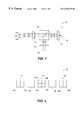
- FIG. 1is a simplified view of an optical head for use in a multi-beam optical disk drive
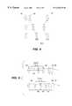
- FIGS. 2A-2Cillustrate alignment of the light beams generated by the laser diodes with the tracks of the optical disk when the system is in alignment, and when there are over-magnification and under-magnification errors, respectively;
- FIG. 3shows an optical sensor used for detecting the degree of magnification error
- FIG. 4shows an embodiment of a variable power optical system
- FIG. 5shows an alternative embodiment of a variable power optical system
- FIGS. 6A-6Billustrate the use of prisms in an anamorphic variable power optical system
- FIG. 7is an illustrative embodiment of a cylindrical lens for use in an alternative embodiment for correcting magnification errors
- FIGS. 8A-8Billustrate correction of magnification errors by rotating the array of laser diodes that generates the writing beams
- FIGS. 9A-9Billustrate correction of magnification errors by rotating the array of photodetector elements that receives the beams reflected from the surface of the optical disk.
- FIG. 10illustrates an alternative detector suitable for use in the present invention.
- FIG. 11shows an illustrative lookup table of magnification error correlated to track position.
- FIG. 1a simplified diagram of an optical head 10 for a multi-beam optical disk drive constructed in accordance with the present invention is described.
- Individual components of optical head 10may comprise elements used in conventional CD-R or DVD-RAM drives.
- a plurality of laser diodes 12 a - 12 egenerate a plurality of light beams which may be used to simultaneously read multiple tracks, or individually modulated to write data on multiple tracks, of optical disk 18 .
- the beamsare collimated by collimator lens 14 , and are focussed onto a surface of optical disk 18 by objective 16 .
- Optical disk 18contains a data layer (not shown) in which the data is recorded, typically in the form of “pits”, having a reflectivity different than the surrounding areas of optical disk 18 .
- This difference in reflectivityis typically achieved by using a data layer comprising a layer of an organic polymer dye disposed in front of a thin reflective film (typically gold).
- the light beamsheat the polymer dye to a predetermined temperature, causing the opacity of the dye to change, and altering the reflectivity of the data layer.
- some recordable optical disksuse physical or chemical properties of the data layer material, such as its magnetic properties, or its ability to polarize incident light, to record the data.
- optical disk 18is preferably pre-formatted, as are most commercially available recordable optical disk types.
- the block headers and tracksare already laid out on optical disk 18 and contain clocking and timecode information.
- the beams used for writingmust be aligned with the pre-formatted tracks.
- the diskis not pre-formatted, then it is sufficient only to maintain the track pitch of the multiple tracks being written within the specification of the appropriate disk type. If the disk is being read, the beams used for reading must be aligned with the tracks.
- the beamsare reflected off of the data layer of optical disk 18 , and are directed toward optical sensor 22 by beam splitter 20 , which may be a half-silvered mirror.
- Lens 24may be provided to further focus the reflected light from the surface of optical disk 18 on to optical sensor 22 .
- Optical sensor 22may be used to detect the focus, tracking, and magnification error of the beams which are used to write to optical disk 18 . Additionally, optical sensor 22 may be used to read data from optical disk 18 when the power of the beams is lowered to permit reading.
- optical head of FIG. 1is intended to be illustrative, not limiting. It is to be understood that many variations and embellishments of the basic optical head are possible.
- beam splitter 20may be a holographic element or half-silvered mirror.
- Several possible configurations of optical heads usable for reading and writing optical disksare discussed in The Compact Disc Handbook , Pohlmann, K., 2d. ed., A-R Editions, 1992.
- the principles of the present inventionare not limited to an optical head as disclosed in FIG. 1, but are easily adaptable to a wide variety of optical head designs, if modified as described hereinafter.
- FIGS. 2A-2Cshow the pre-formatted tracks on optical disk 18 , with the spots projected by the plurality of beams.
- spots 30 a - 30 eprojected by laser diodes 12 a - 12 e , respectively, are aligned with pre-formatted tracks 32 a - 32 e , respectively, so the tracks may be read or written simultaneously.
- the magnification of the optical system which focuses the beams onto the diskmay vary slightly.
- magnification errorThis misalignment is hereinafter referred to as “magnification error.”
- the spacing between spots 30 a - 30 eis greater than the spacing between tracks 32 a - 32 e , so the optical system provides too much magnification.
- FIG. 2Cshows the situation where too little magnification is provided by the system, thereby causing the spacing of spots 30 a - 30 e to be less than the spacing between tracks 32 a - 32 e . Similar errors could also result from variations in the track pitch of optical disk 18 . To permit simultaneous reading or writing of multiple tracks, these magnification errors must be corrected.
- FIG. 3shows a detailed view of optical sensor 22 of FIG. 1 .
- Optical sensor 22includes photodetector elements 34 - 38 , which may be used for reading data from the tracks when the beams are set to a power level appropriate for reading.
- photodetector elements 34 - 38When data is being written to optical disk 18 , light reflected from the pre-formatted tracks of optical disk 18 will be projected onto photodetector elements 34 - 38 .
- Photodetector elements 37 and 38illustratively the outermost elements of the array, further comprise two segments 37 a , 37 b and 38 a , 38 b , respectively, per element.
- a signal proportional to the magnification errorcan be generated by subtracting the sum of the signals from the innermost segments of photodetector elements 37 and 38 from the sum of the signals from the outermost segments of photodetector elements 37 and 38 , in accordance with equation (1):
- photodetector element 34may optionally be configured as a quadrant detector, for use in detecting focus errors using the well-known astigmatism method, using equation (2):
- photodetector elements 37 and 38may be employed to compute a tracking error.
- the sum of the left-hand segments of photodetector elements 37 and 38is subtracted from the sum of the right-hand segments of photodetector elements 37 and 38 , in accordance with equation (3):
- a signal indicative of the tracking errorcould be generated by subtracting the sum of the signals from the left-hand quadrants ( 34 a , 34 c ) of photodetector 34 from the sum of the signals from the right-hand quadrants ( 34 b , 34 d ) of photodetector element 34 .
- the number and configuration of the 15 photo-detector elements shown in FIG. 3must match the number and configuration of the beams used in the multi-beam system. It will further be evident that the detectors shown with reference to FIG. 3 are illustrative. In particular, the magnification error may be computed with any of the detector elements, including the quadrants of photodetector element 34 .
- magnification errormay be most easily and accurately measured using the signals generated by the outermost pair of elements, where the effect of the magnification error is expected to be the largest.
- focus error signal and tracking error signalmay be computed using alternative arrangements, without departing from the principle of the present invention.
- optical disksmay include the track pitch information in a header area of the optical disk. This information is read when the optical disk is inserted into the disk drive, and may be used to adjust the degree of magnification provided by the optical system as described hereinbelow.
- a calibration stepmay be performed when the optical disk is first inserted in the optical disk drive.
- the optical disk driveis programmed to provide a magnification of the optical system that corresponds to a nominal track pitch for a preselected optical disk type.
- the optical diskis scanned and a lookup table of magnification error is generated that is correlated to track position using, for example, track counting or jitter analysis methods.
- the lookup table created during the calibration stepmay be continuously or periodically consulted when simultaneously reading or writing multiple tracks to the optical disk to vary the degree of magnification correction based on local track pitch.
- the lookup table valuesare generated whenever a new optical disk is inserted into the optical disk drive to account for local variations in track pitch, and may be periodically updated during the reading or writing process.
- the lookup table valuesare based on the actual track pitch measured on the optical disk, for example, as a function of radial location on the disk.
- optical head 10is located at a first position, at which the block header (or previously written data) is read.
- Optical head 10is then moved to a second position a known distance from the first position, and the block header information for that track is read. While the optical head is being moved between the first and second positions, the number of tracks crossed are counted. From this information, the actual track pitch of the optical disk may be computed as the known distance divided by the number of tracks skipped.
- the track pitchmay be calculated by determining the number of data blocks that fit into a known number of tracks. Since the length of a data block along the spiral track is known, the length of the spiral portion of the track between the two blocks may be determined from the difference in block numbers read from the block header data. This difference may then be compared to the difference computed for an optical disk having a nominal track pitch, to estimate the actual track pitch of the disk.
- the ratio of the actual track pitch to the nominal track pitchyields the magnification error, which may then be used to adjust the optical system, as described hereinafter.
- the foregoing processmay be repeated along the radius of the disk, thus generating a table of track pitch correlated to track position.
- Lookup table 62contains multiple rows, with each row having a track position and its corresponding magnification error.
- Track positions 1 - 4( 63 a , 64 a , 65 a , 66 a ) have corresponding magnification errors 63 b , 64 b , 65 b and 66 b .
- lookup table 62can contain additional rows and columns, such as columns for the actual and nominal track pitch.
- a table of magnification correctionsis generated, correlated to disk location, that provides the lowest jitter rate, i.e., the lowest error correction rate for the data signals, when reading block header data, or previously written tracks of the optical disk.
- block header information or other datais read from several tracks, and the degree of magnification provided by the optical system is dithered. This in turn effects the quality of the track signals for the data being read, as reflected in the error rate, for example, as determined by conventional ECC circuitry.
- the degree of magnification that produces the lowest error rateis then selected for use in reading data from, or writing data to, the optical disk. position and its corresponding magnification error.
- Track positions 1 - 4( 63 a , 64 a , 65 a , 66 a ) have corresponding magnification errors 63 b , 64 b , 65 b and 66 b .
- lookup table 62can contain additional rows and columns, such as columns for the actual and nominal track pitch.
- optical head 10 of FIG. 1is provided with a capability to vary its optical power or magnification.
- a magnification correction mechanismpreferably disposed in the optical path between laser diodes 12 a - 12 e and optical disk 18 , and more preferably, in the optical path before collimating lens 14 , would enable correction of the spacing of the beams before they are projected onto optical disk 18 .
- FIGS. 4 and 5show two illustrative methods of providing a variable power optical system.
- lens 40remains stationary while a servo system moves lens 42 axially to vary the power of the optical system responsive to the magnification error signal generated by optical sensor 22 .
- Moving lens 42causes a shift in the image plane, so lens 44 must be moved towards or away from lens 42 to counteract the image plane shift.
- the position of lens 44is expected to be a nonlinear function of the position of lens 42 .
- variable power optical systemscomprising a series of alternately fixed lenses 46 and movable lenses 48 .
- Movable lenses 48are linked together, and move axially as a unit to vary the power of the optical system. Some shifting of the image plane occurs as the power is varied, but over small ranges of power change, the image plane shift is small. Additional lenses may be added to reduce image plane shift.
- FIGS. 6A and 6BYet another embodiment of a magnification error correction mechanism of the present invention is shown in FIGS. 6A and 6B.
- prism 50may be inserted into the optical path between laser diodes 12 a - 12 e and optical disk 18 .
- Prism 50may be used as an anamorphic lens, wherein the prism magnifies the beams in a single dimension. This may be used, for example, to reduce the width of the beam spacing from w 1 , to w 2 .
- the power of prism 50is determined by the angle of its faces with respect to the optical path, its power may be varied by rotating prism 50 about a line parallel to its axis, thereby compensating for the magnification errors. This may be accomplished by using a servo system (not shown) to rotate prism 50 responsive to the magnification error signal produced by optical sensor 22 .
- prism 50also causes an angular deviation of the incident light that is a function of the angle of the prism faces with respect to the light.
- a second prismmay be used to eliminate or reduce the angular deviation.
- the angular deviation introduced by prism 52may be counteracted.
- the light exiting prism 54 in the embodiment of FIG. 6Bhas a lateral offset retative to the rays entering prism 52 .
- Relatively small offsetsmay be insignificant, depending upon the size of the detector elements used for imaging the multiple tracks. Larger offsets may appear as tracking errors, and may be compensated for using any of a number of well-known methods for correcting tracking errors. For example, a larger tracking error may be corrected by using optical sensor 22 to generate a tracking error signal as described hereinabove with respect to FIG. 3 .
- Optical head 10may then be moved by a servo system (not shown) responsive to the tracking error signal to compensate for the tracking error.
- Cylindrical lens 56has a radius of curvature that varies along a length of the lens. Cylindrical lens 56 is positioned in the optical path such that its flat face is perpendicular to the optical path and its axis is perpendicular to the line of the laser diodes. Like the prisms of the embodiments of FIGS. 6A and 6B, a cylindrical lens provides magnification in only a single dimension, wherein the degree of magnification is determined by the radius of the curved surface of the lens. By using a lens in which the curvature varies along its length, the horizontal magnification of the images may be controlled through vertical movement of the variable radius cylindrical lens. A servo system (not shown) may be used to move the lens vertically in response to the magnification error signal generated by optical sensor 22 .
- the systems for correcting magnification errors discussed hereinaboveoperate by changing the magnification or optical power of optical head 10 , of FIG. 1 .
- an optical disk readermay compensate for the magnification error by effectively changing the spacing of the laser diodes 12 a — 12 e and, optionally, the spacing of the photodetector elements 34 - 38 , of FIG. 1 .
- An embodiment of such a magnification error compensation systemis described with respect to FIGS. 8A and 8B.
- laser diodes 12 a - 12 ecomprise a rotatable substrate on which the laser-emitting portions are mounted.
- the substratemay be rotated, or pivoted, to a particular orientation angle responsive to the magnification error signal.
- the effective spacing of laser diodes 12 a - 12 eis dependent on the rotation angle ⁇ , and is given by:
- dis the inter-diode spacing
- d′is the effective inter-diode spacing
- laser diodes 12 a - 12 eare oriented at a 45° angle relative to the direction of track image motion, thus the effective inter-diode spacing is equal to d ⁇ cos(45°), or about 71% of d.
- a servo systemmay rotate the array of laser diodes so that they have a larger angle relative to the tracks, as is shown in FIG. 8 B. This rotation effectively increases the inter-diode spacing between laser diodes 12 a - 12 e , as shown by d′′.
- photodetectors 34 - 38may be initially oriented at a 45° 0 angle relative to the direction of track image motion, in alignment with the laser diodes 12 a - 12 e of FIG. 8 A.
- the individual photodetector elements 34 - 38may be replaced by detector 60 .
- Detector 60preferably includes multiple pixels 61 that are employed to image each track. Track detection methods may be used to determine which of the pixels 61 correspond to the beams reflected from the disk, independent of the beam spacing. Thus, when magnification error correction causes the spacings between beams reflected onto detector 60 to vary, the outputs of pixels 61 may be re-ordered to maintain proper alignment.
- Electronic track detector apparatus and methods suitable for this purposeare described in commonly assigned U.S. Pat. Nos. 5,701,283, 5,652,746, 5,627,805, and 5,598,393, which are incorporated herein by reference.
Landscapes
- Physics & Mathematics (AREA)
- Optics & Photonics (AREA)
- Mathematical Physics (AREA)
- Optical Head (AREA)
- Optical Recording Or Reproduction (AREA)
Abstract
Description
Claims (30)
Priority Applications (6)
| Application Number | Priority Date | Filing Date | Title |
|---|---|---|---|
| US09/037,471US6430125B1 (en) | 1996-07-03 | 1998-03-10 | Methods and apparatus for detecting and correcting magnification error in a multi-beam optical disk drive |
| EP99914498AEP1062664A1 (en) | 1998-03-10 | 1999-03-09 | Methods and apparatus for detecting and correcting magnification error in a multi-beam optical disk drive |
| CA002321061ACA2321061A1 (en) | 1998-03-10 | 1999-03-09 | Methods and apparatus for detecting and correcting magnification error in a multi-beam optical disk drive |
| PCT/EP1999/001522WO1999046769A1 (en) | 1998-03-10 | 1999-03-09 | Methods and apparatus for detecting and correcting magnification error in a multi-beam optical disk drive |
| JP2000536073AJP2002507040A (en) | 1998-03-10 | 1999-03-09 | Method and apparatus for detecting and correcting magnification errors in a multi-beam optical disk drive |
| AU33296/99AAU3329699A (en) | 1998-03-10 | 1999-03-09 | Methods and apparatus for detecting and correcting magnification error in a multi-beam optical disk drive |
Applications Claiming Priority (2)
| Application Number | Priority Date | Filing Date | Title |
|---|---|---|---|
| US08/675,526US5729512A (en) | 1996-07-03 | 1996-07-03 | Magnification and tracking error correction system for multiple track optical disk reader |
| US09/037,471US6430125B1 (en) | 1996-07-03 | 1998-03-10 | Methods and apparatus for detecting and correcting magnification error in a multi-beam optical disk drive |
Related Parent Applications (1)
| Application Number | Title | Priority Date | Filing Date |
|---|---|---|---|
| US08/675,526Continuation-In-PartUS5729512A (en) | 1996-07-03 | 1996-07-03 | Magnification and tracking error correction system for multiple track optical disk reader |
Publications (1)
| Publication Number | Publication Date |
|---|---|
| US6430125B1true US6430125B1 (en) | 2002-08-06 |
Family
ID=21894522
Family Applications (1)
| Application Number | Title | Priority Date | Filing Date |
|---|---|---|---|
| US09/037,471Expired - LifetimeUS6430125B1 (en) | 1996-07-03 | 1998-03-10 | Methods and apparatus for detecting and correcting magnification error in a multi-beam optical disk drive |
Country Status (6)
| Country | Link |
|---|---|
| US (1) | US6430125B1 (en) |
| EP (1) | EP1062664A1 (en) |
| JP (1) | JP2002507040A (en) |
| AU (1) | AU3329699A (en) |
| CA (1) | CA2321061A1 (en) |
| WO (1) | WO1999046769A1 (en) |
Cited By (11)
| Publication number | Priority date | Publication date | Assignee | Title |
|---|---|---|---|---|
| US20030090972A1 (en)* | 2001-11-09 | 2003-05-15 | Yuji Handa | Method of controlling data writing velocity and optical disk player |
| US20030223325A1 (en)* | 2002-06-03 | 2003-12-04 | Takeshi Shimano | Optical reproducing apparatus |
| US20040075476A1 (en)* | 2001-02-02 | 2004-04-22 | Fabienne Dreville | Method and device for generating a synchronisation variable and the corresponding integrated circuit and digital disc drive |
| US20050276297A1 (en)* | 2004-05-14 | 2005-12-15 | Sony Corporation | Optical pickup and optical disk apparatus |
| US20050286096A1 (en)* | 2004-06-24 | 2005-12-29 | Daewoo Electronics Corporation | Apparatus and method for compensating for pixel distortion in reproduction of hologram data |
| US20060133232A1 (en)* | 2004-12-20 | 2006-06-22 | Doug Carson & Associates, Inc. | Radial separation distance determination for a data storage medium |
| US20080198466A1 (en)* | 2007-02-21 | 2008-08-21 | Michael Plotkin | Method and apparatus for controlling multiple beam spacing |
| US20080221813A1 (en)* | 2005-05-18 | 2008-09-11 | Koninklijke Philips Electronics, N.V. | Jitter-Based Calibration Procedure With Improved Resolution For Optical Disc Drives |
| US7430154B2 (en) | 2002-08-23 | 2008-09-30 | Dell Products L.P. | Removable storage media drive feature enabling self test without presence of removable media |
| US20110144469A1 (en)* | 2008-05-07 | 2011-06-16 | Patraicia Connolly | Bacterial/Cellular Recognition Impedance Algorithm |
| CN113744766A (en)* | 2020-05-29 | 2021-12-03 | 华为技术有限公司 | Data reading and writing device and data reading and writing method |
Families Citing this family (10)
| Publication number | Priority date | Publication date | Assignee | Title |
|---|---|---|---|---|
| US20030206503A1 (en)* | 1999-12-15 | 2003-11-06 | Kosoburd Tatiana Tania | Multi-element detector and multi-channel signal conditioner for use reading multiple tracks of optical disks having diverse formats |
| WO2001045095A2 (en)* | 1999-12-15 | 2001-06-21 | Zen Research (Ireland), Ltd. | Multi-element detector for use reading multiple tracks of optical disks having diverse formats |
| JP4483021B2 (en)* | 2000-04-19 | 2010-06-16 | ソニー株式会社 | Anamorphic prism, optical head, and optical recording / reproducing apparatus |
| EP1282837A1 (en)* | 2000-05-15 | 2003-02-12 | Lüscher, Ursula | Device, method and computer programme product for the transmission of data |
| WO2005024798A2 (en)* | 2003-09-11 | 2005-03-17 | Koninklijke Philips Electronics N.V. | Tracking method, recording means and a recorder for an optical disc |
| EP1803121A1 (en)* | 2004-10-15 | 2007-07-04 | Koninklijke Philips Electronics N.V. | Multi-dimensional optical scanner |
| WO2006076151A2 (en) | 2004-12-21 | 2006-07-20 | Carnegie Mellon University | Lithography and associated methods, devices, and systems |
| US20060140077A1 (en)* | 2004-12-28 | 2006-06-29 | Quantum Corporation | Focalizer alignment |
| CN101273410A (en)* | 2005-09-29 | 2008-09-24 | 皇家飞利浦电子股份有限公司 | Method and system to improve playability of optical record medium |
| TW200832388A (en)* | 2006-09-20 | 2008-08-01 | Koninkl Philips Electronics Nv | A system and method for determining the position of a plurality of laser spots on an optical disc |
Citations (30)
| Publication number | Priority date | Publication date | Assignee | Title |
|---|---|---|---|---|
| DE2543276A1 (en) | 1975-09-27 | 1977-03-31 | Licentia Gmbh | Reproduction system for data carried on tapes - has monochromatic light source and pick-up units for optical signals to be converted to audio output |
| US4272651A (en) | 1978-04-28 | 1981-06-09 | Matsushita Electric Industrial Co., Ltd. | Optical system having diode laser light source |
| US4459690A (en) | 1981-07-30 | 1984-07-10 | Rca Corporation | Multi-beam optical record and playback apparatus having an improved beam splitter |
| US4536866A (en) | 1978-11-30 | 1985-08-20 | Videonics Of Hawaii, Inc. | Information retrieval system and apparatus |
| US4578786A (en)* | 1984-07-06 | 1986-03-25 | Storage Technology Partners Ii | Track pitch calibration system for use in optical storage devices |
| US4768184A (en)* | 1987-01-23 | 1988-08-30 | General Electric Company | Apparatus and method for minimizing magnification distortion in multi-track optical recording |
| DE3804701A1 (en) | 1987-03-20 | 1988-09-29 | Hitachi Ltd | MULTIPLE-LIGHT SPOT CONTROL DEVICE |
| US4875076A (en) | 1987-06-15 | 1989-10-17 | Canon Kabushiki Kaisha | Exposure apparatus |
| JPH02158931A (en) | 1988-12-12 | 1990-06-19 | Asaka Co Ltd | Multibeam optical disk recording and reproducing device |
| US4953152A (en)* | 1987-01-09 | 1990-08-28 | Hitachi, Ltd. | Mastering machine for making an on-land recording master disk with two beam alignment servo loops |
| EP0441435A1 (en) | 1990-02-06 | 1991-08-14 | Koninklijke Philips Electronics N.V. | Optical scanning device using a plurality of scanning spots |
| US5144616A (en)* | 1989-03-14 | 1992-09-01 | Fuji Xerox Co., Ltd. | Laser diode and multibeam optical head using the laser diode |
| WO1993003481A1 (en) | 1991-07-29 | 1993-02-18 | Lasor Limited | Optical recording apparatus |
| EP0545526A1 (en) | 1991-12-03 | 1993-06-09 | Pioneer Electronic Corporation | Optical pickup apparatus |
| US5283778A (en) | 1991-11-12 | 1994-02-01 | Pioneer Electronic Corporation | Pickup device |
| JPH0696467A (en) | 1992-09-14 | 1994-04-08 | Asahi Optical Co Ltd | Optical recording and reproducing device |
| US5309205A (en) | 1991-09-17 | 1994-05-03 | Kabushiki Kaisha Toshiba | Image forming apparatus having magnification error compensation |
| WO1994019796A1 (en) | 1993-02-17 | 1994-09-01 | Photonics Research Incorporated | Multiple beam optical memory system |
| US5479387A (en)* | 1992-09-24 | 1995-12-26 | Sony Corporation | Optical head including multiple photo detectors for reading signals and error signals for servoing from both a read-only recording medium and a magneto-optical recording medium |
| US5483511A (en) | 1993-02-17 | 1996-01-09 | Vixel Corporation | Multiple beam optical memory system with solid-state lasers |
| US5493553A (en) | 1992-12-22 | 1996-02-20 | Thomson Csf | Method and apparatus for preventing cross-talk during reproduction of data recorded on a high density recording medium |
| US5573492A (en) | 1994-12-28 | 1996-11-12 | Olympus America Inc. | Digitally measuring scopes using a high resolution encoder |
| US5594711A (en) | 1993-11-26 | 1997-01-14 | Canon Kabushiki Kaisha | Optical recording and reproducing apparatus using a plurality of light spots for recording and reproducing |
| US5602383A (en) | 1994-05-17 | 1997-02-11 | Seiko Epson Corporation | Optical apparatus for optically reading and recording information |
| US5729512A (en)* | 1996-07-03 | 1998-03-17 | Zen Research N.V. | Magnification and tracking error correction system for multiple track optical disk reader |
| US5808983A (en)* | 1995-06-16 | 1998-09-15 | Sony Corporation | Recording/reproducing apparatus and method for determining and generating a focus offset valve to focus at an optical storage medium |
| US5815473A (en)* | 1995-04-11 | 1998-09-29 | Ricoh Company, Ltd. | Optical pickup device for detecting tracking error of optical disks with different track pitches |
| US5909418A (en)* | 1994-08-26 | 1999-06-01 | Nippon Conlux Co., Ltd. | Optical information recording device and method for detecting and verifying recorded information |
| US5923632A (en)* | 1994-12-28 | 1999-07-13 | Sony Corporation | Optical pick-up device for a multi-layer recording medium with a photodetector arrangement for focusing and tracking control |
| US5959953A (en)* | 1996-07-03 | 1999-09-28 | Zen Research Nv | Methods and apparatus for performing cross-talk correction in a multi-track optical disk reader based on magnification error |
- 1998
- 1998-03-10USUS09/037,471patent/US6430125B1/ennot_activeExpired - Lifetime
- 1999
- 1999-03-09AUAU33296/99Apatent/AU3329699A/ennot_activeAbandoned
- 1999-03-09CACA002321061Apatent/CA2321061A1/ennot_activeAbandoned
- 1999-03-09EPEP99914498Apatent/EP1062664A1/ennot_activeCeased
- 1999-03-09WOPCT/EP1999/001522patent/WO1999046769A1/ennot_activeApplication Discontinuation
- 1999-03-09JPJP2000536073Apatent/JP2002507040A/enactivePending
Patent Citations (34)
| Publication number | Priority date | Publication date | Assignee | Title |
|---|---|---|---|---|
| DE2543276A1 (en) | 1975-09-27 | 1977-03-31 | Licentia Gmbh | Reproduction system for data carried on tapes - has monochromatic light source and pick-up units for optical signals to be converted to audio output |
| US4272651A (en) | 1978-04-28 | 1981-06-09 | Matsushita Electric Industrial Co., Ltd. | Optical system having diode laser light source |
| US4536866A (en) | 1978-11-30 | 1985-08-20 | Videonics Of Hawaii, Inc. | Information retrieval system and apparatus |
| US4459690A (en) | 1981-07-30 | 1984-07-10 | Rca Corporation | Multi-beam optical record and playback apparatus having an improved beam splitter |
| US4578786A (en)* | 1984-07-06 | 1986-03-25 | Storage Technology Partners Ii | Track pitch calibration system for use in optical storage devices |
| US4953152A (en)* | 1987-01-09 | 1990-08-28 | Hitachi, Ltd. | Mastering machine for making an on-land recording master disk with two beam alignment servo loops |
| US4768184A (en)* | 1987-01-23 | 1988-08-30 | General Electric Company | Apparatus and method for minimizing magnification distortion in multi-track optical recording |
| US4969137A (en) | 1987-03-20 | 1990-11-06 | Hitachi, Ltd. | Optical recording and reproducing apparatus having a multi-spot positioning control mechanism |
| DE3804701A1 (en) | 1987-03-20 | 1988-09-29 | Hitachi Ltd | MULTIPLE-LIGHT SPOT CONTROL DEVICE |
| US4875076A (en) | 1987-06-15 | 1989-10-17 | Canon Kabushiki Kaisha | Exposure apparatus |
| JPH02158931A (en) | 1988-12-12 | 1990-06-19 | Asaka Co Ltd | Multibeam optical disk recording and reproducing device |
| US5144616A (en)* | 1989-03-14 | 1992-09-01 | Fuji Xerox Co., Ltd. | Laser diode and multibeam optical head using the laser diode |
| EP0441435A1 (en) | 1990-02-06 | 1991-08-14 | Koninklijke Philips Electronics N.V. | Optical scanning device using a plurality of scanning spots |
| US5854780A (en)* | 1990-02-06 | 1998-12-29 | U.S. Philips Corporation | Optical scanning device using a plurality of scanning spots |
| WO1993003481A1 (en) | 1991-07-29 | 1993-02-18 | Lasor Limited | Optical recording apparatus |
| US5309205A (en) | 1991-09-17 | 1994-05-03 | Kabushiki Kaisha Toshiba | Image forming apparatus having magnification error compensation |
| US5283778A (en) | 1991-11-12 | 1994-02-01 | Pioneer Electronic Corporation | Pickup device |
| EP0545526A1 (en) | 1991-12-03 | 1993-06-09 | Pioneer Electronic Corporation | Optical pickup apparatus |
| JPH0696467A (en) | 1992-09-14 | 1994-04-08 | Asahi Optical Co Ltd | Optical recording and reproducing device |
| US5479387A (en)* | 1992-09-24 | 1995-12-26 | Sony Corporation | Optical head including multiple photo detectors for reading signals and error signals for servoing from both a read-only recording medium and a magneto-optical recording medium |
| US5493553A (en) | 1992-12-22 | 1996-02-20 | Thomson Csf | Method and apparatus for preventing cross-talk during reproduction of data recorded on a high density recording medium |
| US5808986A (en)* | 1993-02-17 | 1998-09-15 | Vixel Corporation | Multiple beam optical memory system with solid-state lasers |
| US5526182A (en)* | 1993-02-17 | 1996-06-11 | Vixel Corporation | Multiple beam optical memory system |
| US5483511A (en) | 1993-02-17 | 1996-01-09 | Vixel Corporation | Multiple beam optical memory system with solid-state lasers |
| WO1994019796A1 (en) | 1993-02-17 | 1994-09-01 | Photonics Research Incorporated | Multiple beam optical memory system |
| US5594711A (en) | 1993-11-26 | 1997-01-14 | Canon Kabushiki Kaisha | Optical recording and reproducing apparatus using a plurality of light spots for recording and reproducing |
| US5602383A (en) | 1994-05-17 | 1997-02-11 | Seiko Epson Corporation | Optical apparatus for optically reading and recording information |
| US5909418A (en)* | 1994-08-26 | 1999-06-01 | Nippon Conlux Co., Ltd. | Optical information recording device and method for detecting and verifying recorded information |
| US5573492A (en) | 1994-12-28 | 1996-11-12 | Olympus America Inc. | Digitally measuring scopes using a high resolution encoder |
| US5923632A (en)* | 1994-12-28 | 1999-07-13 | Sony Corporation | Optical pick-up device for a multi-layer recording medium with a photodetector arrangement for focusing and tracking control |
| US5815473A (en)* | 1995-04-11 | 1998-09-29 | Ricoh Company, Ltd. | Optical pickup device for detecting tracking error of optical disks with different track pitches |
| US5808983A (en)* | 1995-06-16 | 1998-09-15 | Sony Corporation | Recording/reproducing apparatus and method for determining and generating a focus offset valve to focus at an optical storage medium |
| US5729512A (en)* | 1996-07-03 | 1998-03-17 | Zen Research N.V. | Magnification and tracking error correction system for multiple track optical disk reader |
| US5959953A (en)* | 1996-07-03 | 1999-09-28 | Zen Research Nv | Methods and apparatus for performing cross-talk correction in a multi-track optical disk reader based on magnification error |
Non-Patent Citations (2)
| Title |
|---|
| Smith, W.J., "Anamorphic Systems," Modern Optical Engineering, Jan. 1, 1966, pp. 239-241. |
| Smith, W.J., "Variable Power (Zoom) Systems," Modern Optical Engineering, Jan. 1, 1966, pp. 241-245. |
Cited By (22)
| Publication number | Priority date | Publication date | Assignee | Title |
|---|---|---|---|---|
| US20040075476A1 (en)* | 2001-02-02 | 2004-04-22 | Fabienne Dreville | Method and device for generating a synchronisation variable and the corresponding integrated circuit and digital disc drive |
| US7219297B2 (en)* | 2001-02-02 | 2007-05-15 | Stmicroelectronics Sa | Method and device for generating a synchronization variable and the corresponding integrated circuit and digital disc drive |
| US20030090972A1 (en)* | 2001-11-09 | 2003-05-15 | Yuji Handa | Method of controlling data writing velocity and optical disk player |
| US7023783B2 (en)* | 2001-11-09 | 2006-04-04 | Shinano Kenshi Kabushiki Kaisha | Method of controlling data writing velocity and optical disk player |
| US20030223325A1 (en)* | 2002-06-03 | 2003-12-04 | Takeshi Shimano | Optical reproducing apparatus |
| US7215609B2 (en)* | 2002-06-03 | 2007-05-08 | Hitachi, Ltd. | Optical reproducing apparatus |
| US20080320337A1 (en)* | 2002-08-23 | 2008-12-25 | Dell Products L.P. | Removable Storage Media Drive Feature Enabling Self Test Without Presence of Removable Media |
| US7430154B2 (en) | 2002-08-23 | 2008-09-30 | Dell Products L.P. | Removable storage media drive feature enabling self test without presence of removable media |
| US7969827B2 (en) | 2002-08-23 | 2011-06-28 | Dell Products L.P. | Removable storage media drive feature enabling self test without presence of removable media |
| US20050276297A1 (en)* | 2004-05-14 | 2005-12-15 | Sony Corporation | Optical pickup and optical disk apparatus |
| USRE45496E1 (en)* | 2004-06-24 | 2015-04-28 | Maple Vision Technologies Inc. | Apparatus and method for compensating for pixel distortion in reproduction of hologram data |
| US20050286096A1 (en)* | 2004-06-24 | 2005-12-29 | Daewoo Electronics Corporation | Apparatus and method for compensating for pixel distortion in reproduction of hologram data |
| US7656564B2 (en)* | 2004-06-24 | 2010-02-02 | Daewoo Electronics Corporation | Apparatus and method for compensating for pixel distortion in reproduction of hologram data |
| US20060133232A1 (en)* | 2004-12-20 | 2006-06-22 | Doug Carson & Associates, Inc. | Radial separation distance determination for a data storage medium |
| US7590039B2 (en)* | 2004-12-20 | 2009-09-15 | Doug Carson & Associates, Inc. | Radial separation distance determination for a data storage medium |
| US20080221813A1 (en)* | 2005-05-18 | 2008-09-11 | Koninklijke Philips Electronics, N.V. | Jitter-Based Calibration Procedure With Improved Resolution For Optical Disc Drives |
| US8885239B2 (en) | 2007-02-21 | 2014-11-11 | Hewlett-Packard Development Company, L.P. | Method and apparatus for controlling multiple beam spacing |
| US20150010316A1 (en)* | 2007-02-21 | 2015-01-08 | Hewlett-Packard Development Company, L.P. | Method and Apparatus for Controlling Multiple Beam Spacing |
| US20080198466A1 (en)* | 2007-02-21 | 2008-08-21 | Michael Plotkin | Method and apparatus for controlling multiple beam spacing |
| US10108104B2 (en)* | 2007-02-21 | 2018-10-23 | Hewlett-Packard Development Company, L.P. | Method and apparatus for controlling multiple beam spacing |
| US20110144469A1 (en)* | 2008-05-07 | 2011-06-16 | Patraicia Connolly | Bacterial/Cellular Recognition Impedance Algorithm |
| CN113744766A (en)* | 2020-05-29 | 2021-12-03 | 华为技术有限公司 | Data reading and writing device and data reading and writing method |
Also Published As
| Publication number | Publication date |
|---|---|
| AU3329699A (en) | 1999-09-27 |
| WO1999046769A1 (en) | 1999-09-16 |
| EP1062664A1 (en) | 2000-12-27 |
| CA2321061A1 (en) | 1999-09-16 |
| JP2002507040A (en) | 2002-03-05 |
Similar Documents
| Publication | Publication Date | Title |
|---|---|---|
| US6430125B1 (en) | Methods and apparatus for detecting and correcting magnification error in a multi-beam optical disk drive | |
| US5959953A (en) | Methods and apparatus for performing cross-talk correction in a multi-track optical disk reader based on magnification error | |
| EP0752701B1 (en) | An optical information recording medium and an optical information recording/reproducing device | |
| JP4714200B2 (en) | Method and apparatus for generating a focus error signal in a multi-beam optical disc drive | |
| US6487147B2 (en) | Optical information recording medium and an optical information recording/reproduction device | |
| US20070230296A1 (en) | Multilayer record carrier and method of manufacturing thereof and recording thereon, with reduced transmission differences in the upper layer | |
| US5138598A (en) | Optical disk having relatively wide ram tracks and relatively narrow rom tracks | |
| US6791924B2 (en) | Erasable digital video disk with reference clock track | |
| KR100454452B1 (en) | Optical data recording/reading medium and recording method | |
| US6940805B2 (en) | Methods and apparatus for cross-talk and jitter reduction in multi-beam optical disks | |
| US6449225B1 (en) | Method and apparatus for reading multiple tracks of an optical disk | |
| US6744706B2 (en) | Optical system with tracking controller | |
| JPH01220222A (en) | Reproducing device for optical recording medium |
Legal Events
| Date | Code | Title | Description |
|---|---|---|---|
| AS | Assignment | Owner name:ZEN RESEARCH N.V., NETHERLANDS ANTILLES Free format text:ASSIGNMENT OF ASSIGNORS INTEREST;ASSIGNORS:ALON, AMIR;FINKELSTEIN, JACOB;REEL/FRAME:009277/0387;SIGNING DATES FROM 19980414 TO 19980518 | |
| AS | Assignment | Owner name:ZEN RESEARCH(IRELAND), LTD., IRELAND Free format text:ASSIGNMENT OF ASSIGNORS INTEREST;ASSIGNOR:ZEN RESEARCH N.V.;REEL/FRAME:011473/0649 Effective date:20000928 | |
| STCF | Information on status: patent grant | Free format text:PATENTED CASE | |
| AS | Assignment | Owner name:BLACK VALLEY LIMITED, IRELAND Free format text:CHANGE OF NAME;ASSIGNOR:ZEN RESEARCH (IRELAND) LIMITED;REEL/FRAME:015653/0444 Effective date:20030324 | |
| AS | Assignment | Owner name:DRAGSHOLM WIRELESS HOLDINGS LLC, NEVADA Free format text:ASSIGNMENT OF ASSIGNORS INTEREST;ASSIGNOR:BLACK VALLEY LIMITED;REEL/FRAME:015711/0768 Effective date:20050104 | |
| FEPP | Fee payment procedure | Free format text:PAT HOLDER NO LONGER CLAIMS SMALL ENTITY STATUS, ENTITY STATUS SET TO UNDISCOUNTED (ORIGINAL EVENT CODE: STOL); ENTITY STATUS OF PATENT OWNER: LARGE ENTITY | |
| REFU | Refund | Free format text:REFUND - SURCHARGE, PETITION TO ACCEPT PYMT AFTER EXP, UNINTENTIONAL (ORIGINAL EVENT CODE: R2551); ENTITY STATUS OF PATENT OWNER: LARGE ENTITY | |
| FPAY | Fee payment | Year of fee payment:4 | |
| FEPP | Fee payment procedure | Free format text:PAYOR NUMBER ASSIGNED (ORIGINAL EVENT CODE: ASPN); ENTITY STATUS OF PATENT OWNER: LARGE ENTITY | |
| FPAY | Fee payment | Year of fee payment:8 | |
| FPAY | Fee payment | Year of fee payment:12 | |
| AS | Assignment | Owner name:XYLON LLC, NEVADA Free format text:MERGER;ASSIGNOR:DRAGSHOLM WIRELESS HOLDINGS LLC;REEL/FRAME:036645/0281 Effective date:20150813 |