US6430008B1 - Measurement of tape position error - Google Patents
Measurement of tape position errorDownload PDFInfo
- Publication number
- US6430008B1 US6430008B1US09/539,913US53991300AUS6430008B1US 6430008 B1US6430008 B1US 6430008B1US 53991300 AUS53991300 AUS 53991300AUS 6430008 B1US6430008 B1US 6430008B1
- Authority
- US
- United States
- Prior art keywords
- servo
- read
- module
- tape
- offset
- Prior art date
- Legal status (The legal status is an assumption and is not a legal conclusion. Google has not performed a legal analysis and makes no representation as to the accuracy of the status listed.)
- Expired - Lifetime
Links
- 238000005259measurementMethods0.000titledescription2
- 238000000034methodMethods0.000claimsdescription14
- 238000004891communicationMethods0.000claimsdescription4
- 230000004044responseEffects0.000claimsdescription2
- 238000004364calculation methodMethods0.000abstractdescription11
- 238000010586diagramMethods0.000description26
- 238000012937correctionMethods0.000description15
- 238000006073displacement reactionMethods0.000description15
- 230000007704transitionEffects0.000description14
- 238000004519manufacturing processMethods0.000description3
- 239000010409thin filmSubstances0.000description3
- 230000008859changeEffects0.000description2
- 238000010276constructionMethods0.000description2
- 238000013461designMethods0.000description2
- 238000001514detection methodMethods0.000description2
- 230000005540biological transmissionEffects0.000description1
- 239000000872bufferSubstances0.000description1
- 230000001419dependent effectEffects0.000description1
- 238000003708edge detectionMethods0.000description1
- 238000005516engineering processMethods0.000description1
- 230000006870functionEffects0.000description1
- 238000012986modificationMethods0.000description1
- 230000004048modificationEffects0.000description1
- 230000008569processEffects0.000description1
Images


Classifications
- G—PHYSICS
- G11—INFORMATION STORAGE
- G11B—INFORMATION STORAGE BASED ON RELATIVE MOVEMENT BETWEEN RECORD CARRIER AND TRANSDUCER
- G11B5/00—Recording by magnetisation or demagnetisation of a record carrier; Reproducing by magnetic means; Record carriers therefor
- G11B5/48—Disposition or mounting of heads or head supports relative to record carriers ; arrangements of heads, e.g. for scanning the record carrier to increase the relative speed
- G11B5/58—Disposition or mounting of heads or head supports relative to record carriers ; arrangements of heads, e.g. for scanning the record carrier to increase the relative speed with provision for moving the head for the purpose of maintaining alignment of the head relative to the record carrier during transducing operation, e.g. to compensate for surface irregularities of the latter or for track following
- G11B5/584—Disposition or mounting of heads or head supports relative to record carriers ; arrangements of heads, e.g. for scanning the record carrier to increase the relative speed with provision for moving the head for the purpose of maintaining alignment of the head relative to the record carrier during transducing operation, e.g. to compensate for surface irregularities of the latter or for track following for track following on tapes
Definitions
- the present inventionrelates to determining tape position error caused by tape skew and module misalignment and to repositioning the tape to minimize write element position error.
- Magnetic tapeis commonly used to store voice and data information due to its reliability, cost efficiency, and ease of use. Magnetic tape may be made more useful and cost-effective by increasing the areal density of information stored on the magnetic tape. This has generally been accomplished by including more data tracks on a given width of tape. While allowing more data to be stored, the increase in the density of data tracks requires a narrowing of the width of the data tracks, a narrowing of the spacing between data tracks, or both. As the data tracks are more closely spaced, positioning of the tape with respect to the tape head becomes more critical to reduce the possibility of errors introduced while reading or writing.
- Tape headsgenerally include read elements for reading data from the magnetic tape and write elements for writing data to the magnetic tape.
- read elementsmay be formed in a read module with one read element for each data track that is to be simultaneously read.
- write elementsare manufactured into a write module, with one write element for each data track to be simultaneously written .
- Thin film construction techniquesare used to achieve the small geometries required to produce read elements and write elements capable of accessing densely packed data tracks. Using thin film technology, spacing between read elements or write elements within a module can be preciously maintained.
- a typical tape headmay include a sandwich of one write module between two read modules.
- servo stripes or tracksmay be used to provide a reference point .
- One or more servo stripesmay be used depending upon the number of data tracks which are placed upon the tape.
- Servo read elements in the read modulessense tracking patterns on the servo stripe and produce signals which are received by a control system. The control system moves the head to keep the servo signals at nominal magnitude. The nominal signal occurs when the servo read element is located in a certain position relative to the servo stripe.
- the servo stripemay also contain features, such as synchronization fields, which indicate the beginning of a servo frame at the same location in each servo stripe across the width of the tape.
- the tapemay be skewed at a skew angle relative to the tape head.
- Tape skewcauses several difficulties.
- a second difficultyresults because the servo read elements are not vertically aligned with the write elements. Centering one or more servo stripes across servo read elements in a single read module will result in the data tracks not being aligned over the top of write elements due to the skew angle.
- Another object of the present inventionis to provide for determining the skew of magnetic tape relative to servo readers.
- Still another object of the present inventionis to provide for positioning write elements to compensate for tape skew.
- Yet another object of the present inventionis to provide for determining offset between modules in a multiple module tape head.
- a further object of the present inventionis to provide for positioning write elements to compensate for offset between modules in a multiple module tape head.
- a systemfor measuring position error of a magnetic tape.
- the tapehas data tracks and servo stripes across the tape width.
- Each servo stripehas a periodically spaced sequence of synchronization fields and tracking patterns aligned with similar patterns in other servo stripes across the width of the tape.
- the systemincludes a multiple module tape head with at least one read module and at least one write module.
- a read moduleincludes at least two servo read elements for detecting the synchronization fields.
- the systemalso includes a head control which can detect the presence of a synchronization field passing a first servo element and the presence of a corresponding synchronization field passing a second servo read element. The elapsed time between the detected synchronization fields is determined.
- the tape skewis found based on the determined elapsed time, the distance between the servo read elements, and the tape speed.
- a second read moduleincludes a servo read element aligned with a servo read element in the first read module such that both servo read elements read the same particular servo stripe.
- the head controldetects a tracking pattern on the servo stripe passing the first read module servo read element and determines a first offset as the tape offset relative to the first read module servo read element.
- a second tracking patternis detected from the servo stripe passing the second read module servo read element and a second offset is determined as the tape offset relative to the second read module servo read element.
- the offset of the second read module relative to the first read moduleis determined based on the skew, the first offset, and the second offset.
- the head controllerestimates the offset of each write module relative to the first read module based on the determined offset between the first read module and the second read module and the distance between the first read module and the write module.
- the write moduleincludes at least one servo read element aligned with a servo read element in a read module such that both read elements read a particular servo stripe.
- the head control logicdetects a first tracking pattern on the servo stripe passing the read module servo read element and determines a first offset as the tape offset relative to the read module servo read element.
- a second tracking patternis detected on the servo stripe passing the write module servo read element and a second offset is determined as the tape offset relative to the write module servo read element.
- the offset of the write module relative to the read moduleis determined based on the skew, the first offset, and the second offset.
- a tape deck for accessing a magnetic tapeis also provided.
- the tape deckincludes means for positioning the tape head across the width of the magnetic tape in response to a positioning signal.
- the head controlgenerates the positioning signal based on the determined skew.
- the positioning signalis also based on the offset between read modules or on the offset between one or more write modules and a read module.
- a method for determining position error of a magnetic tapeincludes detecting the presence of a synchronization field passing a first servo read element in a read module. The presence of a corresponding synchronization field passing a second servo read element in the read module is also detected. An elapsed time between the detected synchronization fields is determined. The tape skew is found based on the determined elapsed time and the tape speed.
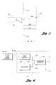
- FIG. 1is a diagram illustrating a tape with no skew traveling across a read-write-read head with no module offsets
- FIG. 2is a diagram illustrating skewed tape traveling across a read-write-read head with no module offsets
- FIG. 3is a diagram illustrating skew calculation according to an embodiment of the present invention.
- FIG. 4is a diagram illustrating the trigonometric relationships associated with the tape elapsed distance
- FIG. 5is a diagram illustrating the trigonometric relationships associated with the skew angle
- FIG. 6is a block diagram of a system for determining the start of a synchronization field on a servo stripe according to an embodiment of the present invention
- FIG. 7is a signal diagram illustrating signals associated with synchronization field detection according to an embodiment of the present invention.
- FIG. 8is a block diagram of a system for determining tape skew according to an embodiment of the present invention.
- FIG. 9is a block diagram illustrating skewed tape traveling across a read-write-read head having module offsets
- FIG. 10is a diagram illustrating module offset calculation according to an embodiment of the present invention.
- FIG. 11is a diagram illustrating the trigonometric relationships associated with the offset between read modules
- FIG. 12is a diagram illustrating the trigonometric relationships associated with positioning the write module to compensate for the offset between read modules
- FIG. 13is a block diagram of a system for determining module offset according to an embodiment of the present invention.
- FIG. 14is a diagram illustrating skewed tape traveling across a read-write-read head having module offsets wherein the write module includes servo read elements according to an embodiment of the present invention.
- FIG. 15is a diagram illustrating write module offset calculation according to an embodiment of the present invention wherein the write module includes a servo read element.
- a tape deckshown generally by 20 , includes tape head 22 for accessing magnetic tape 24 .
- Tape head 22is positioned relative to tape 24 by head position servo 26 .
- Tape 24includes a plurality of data tracks 28 spaced across the width of tape 24 . Tape 24 also includes at least two servo stripes 30 written along the length of tape 24 . Each servo stripe 30 may include periodically spaced features such as synchronization field 32 and tracking pattern 33 . Tape 24 travels across tape head 22 in either tape direction 34 with tape velocity 36 . Only a portion of each data track 28 and servo stripe 30 are shown and only an outline for a portion of tape 24 is provided to permit the details of tape head 22 to be seen.
- Tape head 22 in FIG. 1includes one write module 38 between two read modules 40 to form a read-write-read head.
- Write module 38includes a plurality of write elements 42 constructed to lie along write element axis 44 .
- Write elements 42are magnetic circuits which induce field patterns in data tracks 28 as tape 24 moves past a gap in write element 42 .
- Read module 40is manufactured to have a plurality of read elements 46 constructed along read element axis 48 .
- Read module 40also includes at least two servo read elements 50 aligned with read element axis 48 .
- Read elements 46 and servo read elements 50sense field patterns written onto data tracks 28 and servo strips 30 respectively by detecting changes in inductance or magnetoresistance induced by the field patterns. It will be recognized by one of ordinary skill in the art that the present invention does not depend on the design and construction of write elements 42 , read elements 46 , or servo read elements 50 .
- data track axis 52 running through the center of data track 28is perpendicular to write element axis 44 and read element axis 48 . Also, data track axis 52 passes through the center of each write element 42 and read element 46 which access data track 28 .
- Servo read element 50is positioned to read tracking pattern 33 on servo stripe 30 .
- Head control 54in communication with each servo read element 50 detects tracking pattern 33 and determines the offset of tape 24 relative to tape head 22 in the direction normal to tape direction 34 . If head control 54 detects that servo stripe 30 is not centered on servo read element 50 , head control 54 generates positioning signal 56 causing head position servo 26 to move tape head 22 relative to tape 24 until servo stripe 30 is centered across servo read element 50 . This centers data track 28 across write element 42 and read elements 46 operative to access data track 28 .
- tracking patterns 33are known in the art of magnetic tape recording.
- One techniqueis to write a frequency on servo stripe 30 and erase portions of the background frequency to produce a checkerboard pattern.
- the strength of the background frequency signalwill be at half the strength of the background signal read from servo stripe 30 not part of tracking pattern 33 .
- the background signalwill be relative stronger during one portion of tracking pattern 33 and relatively weaker during another portion of tracking pattern 33 .
- the offset of servo stripe 30 relative to servo read element 50can be determined. This technique is more fully described in U.S. Pat. No. 5,898,533 titled “Tape Servo Pattern With Embedded Servo Track Number Identification” to J. Mantey et al., which is incorporated by reference herein.
- Head position servo 26provides a means for positioning tape head 22 across the width of tape 24 .
- Head position servo 26may include an electric actuator, a hydraulic actuator, a pneumatic actuator, a magnetic actuator, or the like. Force may be transferred through a variety of transmission systems including gear trains, screws, levers, cabling, and belts.
- a voice coil motoris used to position tape head 22 . It is understood by one of ordinary skill in the art that any means to position tape head 22 relative to tape 24 falls within the spirit and scope of the present invention.
- Skew angle 70can be defined as the angle from write element normal 72 to data track axis 52 .
- Write element normal 72is normal to write element axis 44 and passes through the center of write element 42 used to write data track 28 upon which data track axis 52 is centered.
- skew angle 70can be found by sensing corresponding synchronization fields 32 at two servo read elements 50 spaced apart by distance h SS .
- tape head 22can be positioned relative to tape 24 so that data track 28 is centered on write element 42 .
- skew angle 70is also the angle from servo read element normal 80 to servo stripe axis 82 .
- Servo read element normal 80is aligned normal to read element axis 48 through the center of servo read element 50 .
- Servo stripe axis 82is aligned along the center of servo stripe 30 .
- skew angle 70is positive if rotation from servo read element normal 80 to servo stripe axis 82 is counterclockwise.
- Head control 54receives first servo read signal 84 from a first servo read element 50 and receives second servo read signal 86 from a second servo read element 50 ′. Due to skew angle 70 , the change in first servo read signal 84 due to synchronization field 32 will occur at a different time than the change in second servo read signal 86 due to the corresponding synchronization field 32 ′. Using logic described with regard to FIGS. 4-8 below, head control 54 determines the elapsed time, t SS , between detecting synchronization field 32 passing a first servo read element 50 and the corresponding synchronization field 32 ′ passing a second servo read element 50 ′ separated by distance h SS . Let t 50 be the time that synchronization field 32 is detected by servo reader 50 and let t 50′ be the time that synchronization field 32 ′ is detected by servo reader 50 ′. The elapsed time is then given by Equation 1:
- the elapsed timecan be multiplied by tape velocity 36 , v, to give the elapsed displacement, d SS , in a direction parallel to servo stripe axis 82 , between synchronization fields 32 , 32 ′ received by servo read elements 50 , 50 ′, as given by Equation 2:
- the angle ⁇is from read element axis 48 to synchronization field axis 88 between common points on servo stripes 30 .
- the angle ⁇is positive if rotation from read element axis 48 to synchronization field axis 88 is counterclockwise.
- t SS and vcan each be positive or negative.
- d SS and ⁇can be of either sign in accordance with Equations 1 through 3.
- d WRis negative as shown, and thus equal to ⁇ l RW for the illustrated example.
- skew angle 70is positive and offset distance d C is negative, indicating that tape head 22 should be lowered to align write element 42 over data track 28 as shown by 28 ′.
- Equation 6d C ⁇ d WR h SS ⁇ v ⁇ ( t 50 - t 50 ′ ) ( 6 )
- Equations 1 through 6hold for positive or negative velocities. This means that, with the proper sign for d WR , read elements 46 that either lead or follow write elements 42 may be used to compute the offset distance.
- Head control 54includes data qualifier 100 which receives servo read signal 84 , 86 from servo read element 50 , 50 ′.
- the output of data qualifier 100discrete signal 102 , is a square wave having a period equal to the period of sinusoidal servo read signal 84 , 86 .
- Data qualifier 100may also be referred to as a zero crossing detector as is known in the art of data read channels.
- Transition detector 104accepts discrete signal 102 and clock signal 106 from oscillator 108 and produces transition signal 110 .
- Transition signal 110is a short pulse indicating that the front edge of synchronization field 32 has been received by servo read element 50 , 50 ′.
- Data qualifier 100 , transition detector 104 , and oscillator 108are collectively referred to as pulse circuit 112 .
- FIG. 7a signal diagram illustrating signals associated with synchronization field detection according to an embodiment of the present invention is shown. With continuing reference to FIG. 6, the operation of pulse circuit 112 will be further described.
- Servo read signal 84 , 86is a sinusoid at a first frequency when servo read element 50 , 50 ′ is in region 120 just prior to synchronization field 32 and region 122 just after synchronization field 32 .
- Synchronization field 32produces a second frequency sinusoid, shown in FIG. 5 as having a frequency twice as large as the signals produced by regions 120 , 122 .
- Data qualifier 100generates discrete signal 102 .
- Discrete signal 102is a binary signal having two transitions for each period in servo read signal 84 , 86 .
- Transition detector 104includes a counter which counts periods of clock signal 106 occurring between adjacent transitions of discrete signal 102 , indicated by counter value 124 .
- Transition detector 104outputs a pulse on transition signal 110 when a sequence of counter values 124 falls beneath a threshold.
- each period of servo read signal 84 , 86 resulting from synchronization field 32is eight periods of clock signal 106 and each period of servo read signal 84 , 86 in regions 120 , 122 adjacent to synchronization field 32 has a period corresponding to a value of sixteen for counter value 124 .
- Transition detector 104outputs a pulse on transition signal 110 following the third consecutive value for counter value 124 that is less than five. The operation of pulse circuit 112 is further described in U.S. Pat. No.
- Head control 54includes pulse circuit 112 receiving first servo read signal 84 from first servo read element 50 .
- Head control 54includes pulse circuit 112 ′ receiving second servo read signal 86 from second servo read element 50 ′.
- First counter 130is a free-running counter with a count output that can be stored in first latch 132 when the enable input for first latch 132 is asserted.
- second counter 134is a free-running counter with a count output that can be stored in second latch 136 when the enable for second latch 136 is asserted.
- Counters 130 , 134 and latches 132 , 136are clocked by oscillator 138 which may be the same as oscillator 108 .
- Transition signal 110 from pulse circuit 112 operating on first servo read signal 84is connected to the reset of first counter 130 and the enable of second latch 136 .
- transition signal 110 ′ from pulse circuit 112 ′ operating on second servo read signal 86is connected to the reset of second counter 134 and the enable of first latch 132 .
- Pulse circuits 112 , 112 ′, counters 130 , 134 , latches 132 , 136 , and oscillator 138comprise elapsed time circuit 142 .
- Processor 140waits for an asserted pulse on both transition signals 110 , 110 ′. Processor 140 then selects the smaller value between the counts held in first latch 132 and second latch 136 . This value is the number of periods produced by oscillator 138 between when each of synchronization fields 32 , 32 ′ were detected by servo read elements 50 . Processor 140 divides this count by the frequency of oscillator 138 to determine the magnitude of the elapsed time, t SS . The sign of the elapsed time is determined by which latch 132 , 136 holds the smaller value. If latch 132 holds the smaller value, synchronization field 32 was detected by servo read element 50 before synchronization field 32 was detected by servo read element 50 ′.
- processor 140calculates the correction distance, d C .
- Processor 140outputs positioning signal 56 to head position servo 26 based on correction distance d C .
- FIG. 9a diagram illustrating skewed tape traveling over a read-write-read head having module offsets is shown.
- tape head 22may be constructed with modules 38 , 40 being offset from one another in a direction parallel to axes 44 , 48 .
- Such an offset between two read modules 40spaced a distance of l RR′ in the direction of write element normal 72 , is shown by displacement o RR′ .
- the offset between read modules 40can be determined if skew angle 70 is known, as described with regard to FIGS. 10-12 below.
- Head control 54receives signals from servo read element 50 on a first read module 40 and servo read element 50 ′ on a second read module 40 ′.
- Servo read elements 50 , 50 ′are positioned to read the same servo stripe 30 .
- Head control 54detects tracking pattern 33 by reading first tracking pattern signal 150 produced by servo read element 50 .
- head control 54determines the displacement, indicated by x 1 , from the center of servo read element 50 to servo stripe axis 82 .
- head control 54determines the displacement, indicated by x 2 , from the center of servo read element 50 ′ to servo stripe axis 82 .
- Servo read element 50 ′′represents the location of servo read element 50 ′ projected along line 154 parallel to servo stripe axis 82 from head axis 48 ′ onto head axis 48 .
- the offset from 50 ′′ to 50 ′is represented by d V in accordance with Equation 7:
- d RR′is positive as shown and, thus, equal to l RR′ for the illustrated example.
- the servo read element offset, o RR ′, from servo read element 50 to servo read element 50 ′ in the direction parallel to read axes 48 , 48 ′,is represented by the sum of three displacements illustrated on read axis 48 .
- Head control 54may use offset o RR ′ to more accurately position write element 42 relative to write track 28 if it is assumed that the ratio of the offset between write module 38 and read module 40 to the offset between read modules 40 , 40 ′ is in proportion to the ratio of the distance between write axis 44 and servo read axis 48 to the distance between servo read axes 48 and 48 ′.
- Head control 54calculates correction displacement d C by summing the corrections due to skew as described with regard to Equation 5 above and due to the estimated offset of write module 38 relative to read module 40 .
- Head control 54then generates positioning signal 56 based on correction displacement d C for head position servo 26 .
- Head position servo 26responds to positioning signal 56 by moving tape head 22 relative to tape 24 as indicated by data track 28 ′, thus moving data track axis 52 to 52 ′ centered on write element 42 .
- Elapsed time circuit 142accepts first servo read signal 84 and second servo read signal 86 from servo read elements 50 and produces a count proportional to the difference in time between when corresponding synchronization fields 32 cross servo read elements 50 .
- Processor 140uses the count produced by elapsed time circuit 142 and the proper sign to calculate skew angle 70 . A discussion of skew angle calculation is provided with regard to FIGS. 2-8 above.
- Each position circuit 160accepts tracking pattern signal 150 , 152 from servo read element 50 , 50 ′ and determines the offset of tape 24 relative to servo read element 50 , 50 ′.
- Position circuit 160Implementations for position circuit 160 are well known to one of ordinary skill in the art. One implementation that may be used for position circuit 160 is described in U.S. Pat. No. 5,898,533 titled “Tape Servo Pattern With Embedded Servo Track Number Identification” to J. Mantey et al., which is incorporated by reference herein. Processor 140 then calculates correction displacement d C as described with regard to FIGS. 10-12 above. Processor 140 generates positioning signal 56 based on correction displacement d C for use by head position servo 26 .
- FIG. 14a diagram illustrating skewed tape traveling across a read-write-read head having module offsets wherein the write module includes servo read elements according to an embodiment of the present invention is shown.
- Write module 38is constructed to include one or more servo read elements 50 centered on write element axis 44 .
- the offset of write module 38 relative to read module 40 in a direction parallel with write element axis 44can be directly determined as described with regards to FIG. 15 below.
- Write modules including servo read elementsare known to those skilled in the art of tape head design.
- FIG. 15a diagram illustrating write module offset calculation according to an embodiment of the present invention wherein the write module includes a servo read element is shown.
- Calculating the offset for tape head 22 to align data track 28 over write head 42is similar to the calculations described with regards to FIGS. 9-12 above.
- Servo read element 50 in read module 40 and servo read element 50 ′ in write module 38are positioned to read the same servo stripe 30 .
- Head control 54detects tracking pattern 33 passing by servo read element 50 based on first tracking pattern signal 150 received from servo read element 50 .
- Head control 54determines the offset from servo read element 50 to servo stripe axis 82 , indicated by x 1 , based on first tracking pattern signal 150 .
- head control 54detects tracking pattern 33 passing by servo read element 50 ′ using second tracking pattern signal 170 from servo read element 50 ′. Head control 54 determines the offset from servo read element 50 ′ to servo stripe axis 82 , indicated by x 3 , based on second tracking pattern signal 170 .
- the displacements x 1 and x 3are measured parallel to the read and write head axes 48 and 44 , respectively, with the positive direction being toward the top of the figure.
- x 1is positive and X 3 is negative.
- Servo element 50 ′′represents the location of servo read element 50 ′ projected along a line parallel to servo stripe axis 82 from write head axis 44 onto read head axis 48 .
- the offset from 50 ′′ to 50 ′is represented by d W in accordance with Equation 10:
- d RWis positive as shown and, thus, equal to l RW for the illustrated example.
- the offset from servo read element 50 to servo read element 50 ′ in the direction parallel to head axis 48 , 44is o RW .
- Skew angle ⁇ 70 and offsets x 1 and x 3are functions of time and are primarily dependent of the position and skew of tape 24 at the time of measurement. Typically, it is not possible to operate servo read element 50 ′ on write module 38 at the same time write element 42 is in operation. Therefore, write head offset o RW may be estimated during a drive calibration process. Once measured, o RW is maintained in memory within head control 54 and used when needed to produce positioning signal 56 .
- Head control 54can calculate correction distance, d C , required to move write element 42 over data track 28 .
- the correction distance d Cis the sum of the correction due to skew angle 70 , as described with regard to FIG. 3 above, and the correction due to the offset of write module 38 with respect to read module 40 .
- An expression for the correction distanceis provided in Equation 12:
- head position servo 26receives positioning signal 56 and moves head 22 relative to tape 24 to better position write element 42 over data track 28 as indicated by 28 ′.
- the system illustrated in FIG. 13may be used to calculate the correction distance described in FIG. 15 with minor modifications.
- servo read element 50 ′ producing second tracking pattern signal 170replaces servo read element 50 ′ producing second tracking pattern signal 152 .
- processor 140is modified to carry out the calculations described with regard to Equations 10-12 above.
Landscapes
- Adjustment Of The Magnetic Head Position Track Following On Tapes (AREA)
Abstract
Description


Claims (12)
Priority Applications (3)
| Application Number | Priority Date | Filing Date | Title |
|---|---|---|---|
| US09/539,913US6430008B1 (en) | 2000-03-30 | 2000-03-30 | Measurement of tape position error |
| PCT/US2001/009557WO2001075874A2 (en) | 2000-03-30 | 2001-03-23 | Measurement of tape position error |
| AU2001252962AAU2001252962A1 (en) | 2000-03-30 | 2001-03-23 | Measurement of tape position error |
Applications Claiming Priority (1)
| Application Number | Priority Date | Filing Date | Title |
|---|---|---|---|
| US09/539,913US6430008B1 (en) | 2000-03-30 | 2000-03-30 | Measurement of tape position error |
Publications (1)
| Publication Number | Publication Date |
|---|---|
| US6430008B1true US6430008B1 (en) | 2002-08-06 |
Family
ID=24153165
Family Applications (1)
| Application Number | Title | Priority Date | Filing Date |
|---|---|---|---|
| US09/539,913Expired - LifetimeUS6430008B1 (en) | 2000-03-30 | 2000-03-30 | Measurement of tape position error |
Country Status (3)
| Country | Link |
|---|---|
| US (1) | US6430008B1 (en) |
| AU (1) | AU2001252962A1 (en) |
| WO (1) | WO2001075874A2 (en) |
Cited By (39)
| Publication number | Priority date | Publication date | Assignee | Title |
|---|---|---|---|---|
| US20020097518A1 (en)* | 2000-12-12 | 2002-07-25 | Storage Technology Corporation | Track position error determination |
| US20030043498A1 (en)* | 2001-09-05 | 2003-03-06 | Robert Johnson | Magnetic servo of a recording head |
| US6700729B1 (en)* | 2000-10-17 | 2004-03-02 | Hewlett-Packard Development Company | Alignment marks for tape head positioning |
| EP1489600A1 (en) | 2003-06-18 | 2004-12-22 | Hewlett-Packard Development Company, L.P. | Head-track alignment |
| US20050012771A1 (en)* | 2003-07-16 | 2005-01-20 | Leung Sui-Hing | Method and apparatus related to informative data associated with graphical image data |
| US6906888B1 (en)* | 2002-05-20 | 2005-06-14 | Storage Technology Corporation | Method for write track placement correction |
| US20070285831A1 (en)* | 2006-06-08 | 2007-12-13 | Quantum Corporation, A Delaware Corporation | Azimuth Compensation Using Combination Bump Pes Detection |
| US20080068751A1 (en)* | 2006-09-19 | 2008-03-20 | International Business Machines Corporation | Low Track Pitch Write Module And Bidirectional Tape Head |
| US20080068750A1 (en)* | 2006-09-19 | 2008-03-20 | International Business Machines Corporation | Planar Write Module And Hybrid Planar Write-Vertical Read Bidirectional Tape Head |
| US20080068752A1 (en)* | 2006-09-19 | 2008-03-20 | International Business Machines Corporation | Planar Bidirectional Tape Head With Planar Read And Write Elements |
| US20080189214A1 (en)* | 2006-10-17 | 2008-08-07 | Clay Von Mueller | Pin block replacement |
| US20080288403A1 (en)* | 2007-05-18 | 2008-11-20 | Clay Von Mueller | Pin encryption device security |
| US20090141405A1 (en)* | 2007-12-04 | 2009-06-04 | Sun Microsystems, Inc. | Transducer positioning assembly |
| US20090213489A1 (en)* | 2008-02-25 | 2009-08-27 | International Business Machines Corporation | Method and system for servo stripe width detection and compensation |
| US20090268339A1 (en)* | 2008-04-29 | 2009-10-29 | Sun Microsystems, Inc. | Technique for signal and transducer alignment in a tape drive |
| US20090316296A1 (en)* | 2008-06-18 | 2009-12-24 | Giovanni Cherubini | Servo control in tape drives |
| US7725726B2 (en) | 1996-02-15 | 2010-05-25 | Semtek Innovative Solutions Corporation | Method and apparatus for securing and authenticating encoded data and documents containing such data |
| US7740173B2 (en) | 2004-09-07 | 2010-06-22 | Semtek Innovative Solutions Corporation | Transparently securing transactional data |
| US20100315739A1 (en)* | 2009-06-10 | 2010-12-16 | International Business Machines Corporation | Apparatus and method to adjust the orientation of a read head to correct for dynamic skew |
| US7957088B1 (en)* | 2010-03-02 | 2011-06-07 | International Business Machines Corporation | Track compensation and skew compensation for drives having flangeless rollers and systems thereof |
| US7961421B1 (en)* | 2010-03-02 | 2011-06-14 | International Business Machines Corporation | Servo band identification and initial skew estimation in drives having flangeless rollers and systems thereof |
| US8144940B2 (en) | 2008-08-07 | 2012-03-27 | Clay Von Mueller | System and method for authentication of data |
| US8251283B1 (en) | 2009-05-08 | 2012-08-28 | Oberon Labs, LLC | Token authentication using spatial characteristics |
| CN102725792A (en)* | 2010-01-28 | 2012-10-10 | 国际商业机器公司 | Method and apparatus for operating a storage device |
| US20120268842A1 (en)* | 2009-12-21 | 2012-10-25 | International Business Machines Corporation | Method and apparatus for operating a storage device |
| US8355982B2 (en) | 2007-08-16 | 2013-01-15 | Verifone, Inc. | Metrics systems and methods for token transactions |
| US8595490B2 (en) | 2006-10-17 | 2013-11-26 | Verifone, Inc. | System and method for secure transaction |
| US8638523B2 (en)* | 2012-07-02 | 2014-01-28 | International Business Machines Corporation | Enabling partial write during a tape skew |
| US20140204483A1 (en)* | 2011-09-29 | 2014-07-24 | International Business Machines Corporation | Servo control |
| US8824083B1 (en)* | 2013-07-31 | 2014-09-02 | Oracle International Corporation | Calibration system for limiting tape head assembly positioning errors during data writing and reading of tape in tape drive |
| US8891198B2 (en) | 2012-07-27 | 2014-11-18 | International Business Machines Corporation | Method and apparatus for operating a tape storage device |
| US9218839B2 (en) | 2012-04-27 | 2015-12-22 | Globalfoundries Inc. | Operating a tape storage device |
| US9361617B2 (en) | 2008-06-17 | 2016-06-07 | Verifone, Inc. | Variable-length cipher system and method |
| US9390759B2 (en) | 2014-04-16 | 2016-07-12 | International Business Machines Corporation | Skew estimation for a tape storage device |
| US10008226B1 (en) | 2017-06-28 | 2018-06-26 | International Business Machines Corporation | Dynamic head offset selection for tape drive |
| US11145323B1 (en)* | 2020-11-30 | 2021-10-12 | International Business Machines Corporation | Accurate skew determination for magnetic tapes experiencing the effects of tape dimensional instability |
| US11557319B1 (en)* | 2021-08-24 | 2023-01-17 | Seagate Technology Llc | Read offset calibration for error recovery |
| US11568895B1 (en) | 2021-09-03 | 2023-01-31 | Seagate Technology Llc | Read offset calibration for error recovery |
| US20240386911A1 (en)* | 2021-11-05 | 2024-11-21 | Sony Group Corporation | Servo reproduction apparatus, servo reproduction head, reproduction head, and method of producing a magnetic tape |
Families Citing this family (4)
| Publication number | Priority date | Publication date | Assignee | Title |
|---|---|---|---|---|
| US10297280B1 (en) | 2018-07-24 | 2019-05-21 | International Business Machines Corporation | Compensation for nonlinearity in servo patterns |
| US10366716B1 (en) | 2018-07-24 | 2019-07-30 | International Business Machines Corporation | Characterization of nonlinearity in servo patterns |
| US11676626B1 (en) | 2022-03-11 | 2023-06-13 | Western Digital Technologies, Inc. | Tape head having joined modules |
| US11545184B1 (en) | 2022-03-28 | 2023-01-03 | Western Digital Technologies, Inc. | Joined multi-module tape recording head |
Citations (7)
| Publication number | Priority date | Publication date | Assignee | Title |
|---|---|---|---|---|
| US3678220A (en) | 1971-05-26 | 1972-07-18 | Ibm | Angulated positioning marks for moving web |
| US4258398A (en) | 1979-10-12 | 1981-03-24 | Eastman Kodak Company | Apparatus for preventing flutter and skew in electrical signals |
| US4392163A (en) | 1979-09-28 | 1983-07-05 | U.S. Philips Corporation | Magnetic tape recording and/or reproducing apparatus with automatic head positioning |
| US4506309A (en) | 1982-12-17 | 1985-03-19 | Pericomp Corporation | Tape drive calibration meter |
| EP0420374A2 (en) | 1989-09-27 | 1991-04-03 | Archive Corporation | Method to compensate for tape slope and head azimuth errors |
| US5898533A (en) | 1997-02-21 | 1999-04-27 | Storage Technology Corporation | Tape servo pattern with embedded servo track number identification |
| US5973869A (en) | 1997-02-21 | 1999-10-26 | Storage Technology Corporation | Servo frame edge detection for tape servo pattern with synchronization field |
- 2000
- 2000-03-30USUS09/539,913patent/US6430008B1/ennot_activeExpired - Lifetime
- 2001
- 2001-03-23WOPCT/US2001/009557patent/WO2001075874A2/enactiveApplication Filing
- 2001-03-23AUAU2001252962Apatent/AU2001252962A1/ennot_activeAbandoned
Patent Citations (7)
| Publication number | Priority date | Publication date | Assignee | Title |
|---|---|---|---|---|
| US3678220A (en) | 1971-05-26 | 1972-07-18 | Ibm | Angulated positioning marks for moving web |
| US4392163A (en) | 1979-09-28 | 1983-07-05 | U.S. Philips Corporation | Magnetic tape recording and/or reproducing apparatus with automatic head positioning |
| US4258398A (en) | 1979-10-12 | 1981-03-24 | Eastman Kodak Company | Apparatus for preventing flutter and skew in electrical signals |
| US4506309A (en) | 1982-12-17 | 1985-03-19 | Pericomp Corporation | Tape drive calibration meter |
| EP0420374A2 (en) | 1989-09-27 | 1991-04-03 | Archive Corporation | Method to compensate for tape slope and head azimuth errors |
| US5898533A (en) | 1997-02-21 | 1999-04-27 | Storage Technology Corporation | Tape servo pattern with embedded servo track number identification |
| US5973869A (en) | 1997-02-21 | 1999-10-26 | Storage Technology Corporation | Servo frame edge detection for tape servo pattern with synchronization field |
Cited By (69)
| Publication number | Priority date | Publication date | Assignee | Title |
|---|---|---|---|---|
| US7725726B2 (en) | 1996-02-15 | 2010-05-25 | Semtek Innovative Solutions Corporation | Method and apparatus for securing and authenticating encoded data and documents containing such data |
| US6898045B2 (en)* | 2000-10-17 | 2005-05-24 | Hewlett-Packard Development Company, L.P. | Media with pre-recorded alignment transitions |
| US6700729B1 (en)* | 2000-10-17 | 2004-03-02 | Hewlett-Packard Development Company | Alignment marks for tape head positioning |
| US20040109257A1 (en)* | 2000-10-17 | 2004-06-10 | Beck Patricia A. | Media with pre-recorded alignment transitions |
| US6768606B2 (en)* | 2000-12-12 | 2004-07-27 | Storage Technology Corporation | Track position error determination |
| US20020097518A1 (en)* | 2000-12-12 | 2002-07-25 | Storage Technology Corporation | Track position error determination |
| US6856484B2 (en)* | 2001-09-05 | 2005-02-15 | Quantum Corporation | Magnetic servo of a recording head |
| US20030043498A1 (en)* | 2001-09-05 | 2003-03-06 | Robert Johnson | Magnetic servo of a recording head |
| US6906888B1 (en)* | 2002-05-20 | 2005-06-14 | Storage Technology Corporation | Method for write track placement correction |
| US20040257694A1 (en)* | 2003-06-18 | 2004-12-23 | Knowles Vernon L. | Head-track alignment |
| US6937425B2 (en) | 2003-06-18 | 2005-08-30 | Hewlett-Packard Development Company, L.P. | Head-track alignment |
| EP1489600A1 (en) | 2003-06-18 | 2004-12-22 | Hewlett-Packard Development Company, L.P. | Head-track alignment |
| US20050012771A1 (en)* | 2003-07-16 | 2005-01-20 | Leung Sui-Hing | Method and apparatus related to informative data associated with graphical image data |
| US6942312B2 (en)* | 2003-07-16 | 2005-09-13 | Hewlett-Packard Development Company, L.P. | Method and apparatus related to informative data associated with graphical image data |
| US8249993B2 (en) | 2004-09-07 | 2012-08-21 | Verifone, Inc. | Transparently securing data for transmission on financial networks |
| US7740173B2 (en) | 2004-09-07 | 2010-06-22 | Semtek Innovative Solutions Corporation | Transparently securing transactional data |
| US7436621B2 (en)* | 2006-06-08 | 2008-10-14 | Quantum Corporation | Azimuth compensation using combination bump pes detection |
| US20070285831A1 (en)* | 2006-06-08 | 2007-12-13 | Quantum Corporation, A Delaware Corporation | Azimuth Compensation Using Combination Bump Pes Detection |
| US20100110586A1 (en)* | 2006-09-19 | 2010-05-06 | International Business Machines Corporation | Planar Bidirectional Tape Head With Planar Read And Write Elements |
| US20080068752A1 (en)* | 2006-09-19 | 2008-03-20 | International Business Machines Corporation | Planar Bidirectional Tape Head With Planar Read And Write Elements |
| US8760803B2 (en)* | 2006-09-19 | 2014-06-24 | International Business Machines Corporation | Low track pitch write module and bidirectional tape head |
| US20080068751A1 (en)* | 2006-09-19 | 2008-03-20 | International Business Machines Corporation | Low Track Pitch Write Module And Bidirectional Tape Head |
| US8139318B2 (en) | 2006-09-19 | 2012-03-20 | International Business Machines Corporation | Planar bidirectional tape head with planar read and write elements |
| US8130467B2 (en) | 2006-09-19 | 2012-03-06 | International Business Machines Corporation | Planar write module and hybrid planar write-vertical read bidirectional tape head |
| US20110222187A1 (en)* | 2006-09-19 | 2011-09-15 | International Business Machines Corporation | Low Track Pitch Write Module And Bidirectional Tape Head |
| US7978429B2 (en)* | 2006-09-19 | 2011-07-12 | International Business Machines Corporation | Low track pitch write module and bidirectional tape head |
| US20100110587A1 (en)* | 2006-09-19 | 2010-05-06 | International Business Machines Corporation | Planar Write Module And Hybrid Planar Write-Vertical Read Bidirectional Tape Head |
| US20080068750A1 (en)* | 2006-09-19 | 2008-03-20 | International Business Machines Corporation | Planar Write Module And Hybrid Planar Write-Vertical Read Bidirectional Tape Head |
| US8595490B2 (en) | 2006-10-17 | 2013-11-26 | Verifone, Inc. | System and method for secure transaction |
| US8769275B2 (en) | 2006-10-17 | 2014-07-01 | Verifone, Inc. | Batch settlement transactions system and method |
| US9818108B2 (en) | 2006-10-17 | 2017-11-14 | Verifone, Inc. | System and method for updating a transactional device |
| US9123042B2 (en) | 2006-10-17 | 2015-09-01 | Verifone, Inc. | Pin block replacement |
| US20080189214A1 (en)* | 2006-10-17 | 2008-08-07 | Clay Von Mueller | Pin block replacement |
| US9141953B2 (en) | 2006-10-17 | 2015-09-22 | Verifone, Inc. | Personal token read system and method |
| US20080288403A1 (en)* | 2007-05-18 | 2008-11-20 | Clay Von Mueller | Pin encryption device security |
| US8355982B2 (en) | 2007-08-16 | 2013-01-15 | Verifone, Inc. | Metrics systems and methods for token transactions |
| US7706101B2 (en) | 2007-12-04 | 2010-04-27 | Sun Microsystems, Inc. | Transducer positioning assembly |
| US20090141405A1 (en)* | 2007-12-04 | 2009-06-04 | Sun Microsystems, Inc. | Transducer positioning assembly |
| US20090213489A1 (en)* | 2008-02-25 | 2009-08-27 | International Business Machines Corporation | Method and system for servo stripe width detection and compensation |
| US7724466B2 (en) | 2008-02-25 | 2010-05-25 | International Business Machines Corporation | Method and system for servo stripe width detection and compensation |
| US20090268339A1 (en)* | 2008-04-29 | 2009-10-29 | Sun Microsystems, Inc. | Technique for signal and transducer alignment in a tape drive |
| US7660069B2 (en)* | 2008-04-29 | 2010-02-09 | Sun Microsystems, Inc. | Technique for signal and transducer alignment in a tape drive |
| US9361617B2 (en) | 2008-06-17 | 2016-06-07 | Verifone, Inc. | Variable-length cipher system and method |
| US20090316296A1 (en)* | 2008-06-18 | 2009-12-24 | Giovanni Cherubini | Servo control in tape drives |
| US7876521B2 (en) | 2008-06-18 | 2011-01-25 | International Business Machines Corporation | Servo control in tape drives |
| US8144940B2 (en) | 2008-08-07 | 2012-03-27 | Clay Von Mueller | System and method for authentication of data |
| US8251283B1 (en) | 2009-05-08 | 2012-08-28 | Oberon Labs, LLC | Token authentication using spatial characteristics |
| US7948706B2 (en) | 2009-06-10 | 2011-05-24 | International Business Machines Corporation | Apparatus and method to adjust the orientation of a read head to correct for dynamic skew |
| US20100315739A1 (en)* | 2009-06-10 | 2010-12-16 | International Business Machines Corporation | Apparatus and method to adjust the orientation of a read head to correct for dynamic skew |
| DE112010004916B4 (en) | 2009-12-21 | 2025-08-21 | International Business Machines Corporation | Method and device for operating a storage unit |
| US8643975B2 (en)* | 2009-12-21 | 2014-02-04 | International Business Machines Corporation | Method and apparatus for operating a storage device |
| US20120268842A1 (en)* | 2009-12-21 | 2012-10-25 | International Business Machines Corporation | Method and apparatus for operating a storage device |
| DE112011100370B4 (en) | 2010-01-28 | 2022-02-10 | International Business Machines Corporation | Method and device for operating a memory unit |
| CN102725792A (en)* | 2010-01-28 | 2012-10-10 | 国际商业机器公司 | Method and apparatus for operating a storage device |
| CN102725792B (en)* | 2010-01-28 | 2015-04-08 | 国际商业机器公司 | Method and apparatus for operating a storage device |
| US7957088B1 (en)* | 2010-03-02 | 2011-06-07 | International Business Machines Corporation | Track compensation and skew compensation for drives having flangeless rollers and systems thereof |
| US7961421B1 (en)* | 2010-03-02 | 2011-06-14 | International Business Machines Corporation | Servo band identification and initial skew estimation in drives having flangeless rollers and systems thereof |
| US9251828B2 (en)* | 2011-09-29 | 2016-02-02 | International Business Machines Corporation | Servo control |
| US20140204483A1 (en)* | 2011-09-29 | 2014-07-24 | International Business Machines Corporation | Servo control |
| US9218839B2 (en) | 2012-04-27 | 2015-12-22 | Globalfoundries Inc. | Operating a tape storage device |
| US8638523B2 (en)* | 2012-07-02 | 2014-01-28 | International Business Machines Corporation | Enabling partial write during a tape skew |
| US8891198B2 (en) | 2012-07-27 | 2014-11-18 | International Business Machines Corporation | Method and apparatus for operating a tape storage device |
| US8824083B1 (en)* | 2013-07-31 | 2014-09-02 | Oracle International Corporation | Calibration system for limiting tape head assembly positioning errors during data writing and reading of tape in tape drive |
| US9390759B2 (en) | 2014-04-16 | 2016-07-12 | International Business Machines Corporation | Skew estimation for a tape storage device |
| US10008226B1 (en) | 2017-06-28 | 2018-06-26 | International Business Machines Corporation | Dynamic head offset selection for tape drive |
| US11145323B1 (en)* | 2020-11-30 | 2021-10-12 | International Business Machines Corporation | Accurate skew determination for magnetic tapes experiencing the effects of tape dimensional instability |
| US11557319B1 (en)* | 2021-08-24 | 2023-01-17 | Seagate Technology Llc | Read offset calibration for error recovery |
| US11568895B1 (en) | 2021-09-03 | 2023-01-31 | Seagate Technology Llc | Read offset calibration for error recovery |
| US20240386911A1 (en)* | 2021-11-05 | 2024-11-21 | Sony Group Corporation | Servo reproduction apparatus, servo reproduction head, reproduction head, and method of producing a magnetic tape |
Also Published As
| Publication number | Publication date |
|---|---|
| AU2001252962A1 (en) | 2001-10-15 |
| WO2001075874A3 (en) | 2002-01-03 |
| WO2001075874A2 (en) | 2001-10-11 |
Similar Documents
| Publication | Publication Date | Title |
|---|---|---|
| US6430008B1 (en) | Measurement of tape position error | |
| US6236525B1 (en) | Tape head with pattern timing for servo writing application | |
| KR100620829B1 (en) | Method and system for transverse position recovery of servo system with respect to longitudinal servo band of magnetic tape | |
| EP0940807B1 (en) | Linear speed measurement independent of lateral position in linear tape systems | |
| US7489465B2 (en) | Apparatus, system, and method for timing based servo tape formating | |
| US4588882A (en) | Skew detection system for optically read data | |
| US7102847B2 (en) | Identification of laterally positioned servo bands employing differentiating characteristics of servo patterns | |
| US6744594B2 (en) | Servo write head with gaps for writing high and low frequency transitions | |
| US7724466B2 (en) | Method and system for servo stripe width detection and compensation | |
| US7684143B2 (en) | Apparatus, system, and method for limiting frame spacing error during timing-based servo pattern fabrication | |
| US5946159A (en) | Servo edge correction using edge samples taken by independently positioned servo elements | |
| US7903368B2 (en) | Tape cartridge having tape media with longitudinally shifted servo pattern for increased sampling rate | |
| US7403350B2 (en) | Multiple servo sensor configuration for magnetic tape timing based servo | |
| US6710967B2 (en) | High frequency and low frequency servo pattern | |
| US3678220A (en) | Angulated positioning marks for moving web | |
| US6512651B1 (en) | Helical scan tape track following | |
| US7920356B2 (en) | Method and system for providing a longitudinally shifted servo pattern for increased sampling rate | |
| US6768606B2 (en) | Track position error determination | |
| US6023385A (en) | Tape servo pattern with enhanced synchronization properties | |
| US20060044671A1 (en) | Servo head with varying write gap width | |
| US7289289B2 (en) | Recording servo stripes onto a servo track | |
| US6903895B2 (en) | Tape drive servo operation by use of servo pattern width measurements | |
| US5973869A (en) | Servo frame edge detection for tape servo pattern with synchronization field | |
| EP0538835B1 (en) | Recording and reproducing apparatus | |
| JP4072964B2 (en) | Linear data storage tape, separate servo band writing method, servo pattern writer, magnetic tape cartridge, servo tape, to identify transversely arranged servo bands that use servo pattern differentiation characteristics Reader and magnetic tape drive |
Legal Events
| Date | Code | Title | Description |
|---|---|---|---|
| AS | Assignment | Owner name:STORAGE TECHNOLOGY CORPORATION, COLORADO Free format text:INVALID ASSIGNMENT;ASSIGNORS:TRABERT, STEVEN G.;MANTEY, JOHN P.;REEL/FRAME:011968/0869;SIGNING DATES FROM 20000321 TO 20000330 Owner name:STORAGE TECHNOLOGY CORPORATION, COLORADO Free format text:ASSIGNMENT OF ASSIGNORS INTEREST;ASSIGNORS:TRABERT, STEVEN G.;MANTEY, JOHN P.;REEL/FRAME:011970/0156;SIGNING DATES FROM 20000321 TO 20000330 | |
| STCF | Information on status: patent grant | Free format text:PATENTED CASE | |
| FPAY | Fee payment | Year of fee payment:4 | |
| FPAY | Fee payment | Year of fee payment:8 | |
| FPAY | Fee payment | Year of fee payment:12 | |
| AS | Assignment | Owner name:ORACLE AMERICA, INC., CALIFORNIA Free format text:MERGER AND CHANGE OF NAME;ASSIGNORS:SUN MICROSYSTEMS, INC.;ORACLE USA, INC.;ORACLE AMERICA, INC.;REEL/FRAME:037692/0970 Effective date:20100212 Owner name:SUN MICROSYSTEMS, INC., CALIFORNIA Free format text:MERGER;ASSIGNOR:STORAGE TECHNOLOGY CORPORATION;REEL/FRAME:037695/0339 Effective date:20061222 |