US6429857B1 - Apparatus and method to improve resolution of infrared touch systems - Google Patents
Apparatus and method to improve resolution of infrared touch systemsDownload PDFInfo
- Publication number
- US6429857B1 US6429857B1US09/728,999US72899900AUS6429857B1US 6429857 B1US6429857 B1US 6429857B1US 72899900 AUS72899900 AUS 72899900AUS 6429857 B1US6429857 B1US 6429857B1
- Authority
- US
- United States
- Prior art keywords
- infrared
- touch
- axis
- transmitters
- coordinate
- Prior art date
- Legal status (The legal status is an assumption and is not a legal conclusion. Google has not performed a legal analysis and makes no representation as to the accuracy of the status listed.)
- Expired - Lifetime
Links
Images


Classifications
- G—PHYSICS
- G06—COMPUTING OR CALCULATING; COUNTING
- G06F—ELECTRIC DIGITAL DATA PROCESSING
- G06F3/00—Input arrangements for transferring data to be processed into a form capable of being handled by the computer; Output arrangements for transferring data from processing unit to output unit, e.g. interface arrangements
- G06F3/01—Input arrangements or combined input and output arrangements for interaction between user and computer
- G06F3/03—Arrangements for converting the position or the displacement of a member into a coded form
- G06F3/041—Digitisers, e.g. for touch screens or touch pads, characterised by the transducing means
- G06F3/042—Digitisers, e.g. for touch screens or touch pads, characterised by the transducing means by opto-electronic means
- G06F3/0421—Digitisers, e.g. for touch screens or touch pads, characterised by the transducing means by opto-electronic means by interrupting or reflecting a light beam, e.g. optical touch-screen
Definitions
- This inventiongenerally relates to infrared (“IR”) enabled touch systems or touch screens. More particularly, the present invention is directed to an inventive system and method to improve the resolution of IR touch systems.
- the system and methodprovide a higher resolution for determining the location of a touch on the screen through the use of on-axis and off-axis IR transmitter-receiver detection.
- the touch locationis determined by a multiple-step process of first identifying a coarse touch location and then determining a finer location for the touch within the coarse location area.
- the increased resolution of touch locationis achievable with the inventive system and method without the need for an increased density of IR transmitters and receivers or the need for increased processor speed.
- Touch systemsare becoming more prevalent in everyday activities. In addition to touch systems being used in money access centers, lobby directories, museum and entertainment kiosks, and automobile positioning system displays, miniaturized touch systems have become the technology medium of choice for pocket diaries and organizers. While IR touch systems may be used in these applications, in order to be successful in these and other emerging markets, the determination of touch location in touch systems, including IR touch systems, must be made quickly, accurately and precisely. This is especially the case for pocket diaries which may use a relatively small point stylus or pointer as the user's means of identifying a desired operation or system selection.
- IR transmitterstypically light emitting diodes (“LEDs”)
- IR receiverstypically phototransistors (“photos”).
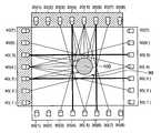
- FIG. 1An example illustration of a prior art touch screen is shown in FIG. 1.
- a set of n IR receivers 30 ( 1 ) to 30 (n) and another set of m IR receivers 50 ( 1 ) to 50 (m),are positioned along the opposite edges of the touch screen 11 such that each receiver 30 (i) and 50 (i) is aligned on-axis with an opposing transmitter, respectively 20 (i) and 40 (i).
- the number of transmitters used along the screen perimeterequals the number of receivers positioned along the opposing screen edge, because the transmitters are each aligned on-axis with a receiver.
- the typical touch screen 11creates a Cartesian coordinate grid of x-coordinate transmitter-receiver pairs, for example x-coordinate pair 20 ( 1 ) and 30 ( 1 ), and y-coordinate transmitter-receiver pairs, for example y-coordinate pair 40 ( 3 ) and 50 ( 3 ).
- the detection patternis accordingly an orthogonal grid of x and y coordinates.
- the location of a touchis determined by scanning the x-coordinate pairs and y-coordinate pairs and identifying which transmitter-receiver pairs show a blockage of IR light.
- the scanning processentails activation of each receiver 30 (i) and 50 (i) and activating, or flashing, the opposing transmitter respectively 20 (i) and 40 (i), detecting whether the transmitter 20 (i) and 40 (i) IR signal is received by the respective on-axis receiver 30 (i) or 50 (i), and then deactivating each receiver 30 (i) and 50 (i).
- This receiver activation, on-axis transmitter flash, receiver deactivation processis repeated for each on-axis transmitter-receiver pair until all transmitter-receiver pairs are scanned.
- the accuracy and precision of the location of a touch for a conventional touch systemis dependent upon the density or number of transmitters and receivers positioned along the perimeter of the screen 11 .
- One problem with such an orthogonal detection pattern, as illustrated in FIG. 1,is that if a touch diameter 95 is less than the spacing of adjacent transmitters and adjacent receivers, a touch may go undetected as being in an area where no beam crosses.
- the time period required to make the touch location determinationis dependent upon the speed of the processor used to activate and flash the transmitters and receivers, and to detect whether the emitted IR signal is received by the receiver. Obviously, unless the processing capability of the system is increased, as more transmitter-receiver pairs are included in the touch system, the time to identify a touch location will increase along with the time period to scan the complete set of transmitter-receiver pairs.
- IR transmitters and receivers, or system optoelectronicscomprise a significant portion of the overall cost of an IR touch system
- an increase in the number of optoelectronic deviceswould result in a dramatic increase in the overall system cost.
- processor electronicsare another significant portion of the cost of an IR touch system
- an increase in processing speed to maintain a maximum time period for touch identificationwould likewise cause a substantial increase in the system cost.
- one device described in Japanese Patent Application No. TOKKAI HEI 11-232024 for an Optical Position Detection Deviceprovides for the detection of two or more adjacent phototransistors within the range of light emitted from an opposing light emitting diode.
- the object of the Alpine systemis to eliminate the restrictions of the prior art with respect to the number, position and placement of LEDs and phototransistors that would allow for possible improvements in position detection accuracy. While apparently describing detection of LED output through the use of off-axis phototransistors, the Alpine system does not appear to describe or disclose any method for efficiently scanning the LED-phototransistor pairs.
- the device operation descriptionappears to call for the sequential cycling all LEDs and detecting multiple phototransistors for each of the LEDs activated.
- Such a devicewould require significantly increased computer processing capability to handle the increased information provided from detecting multiple phototransistors for every LED, and cycling through each LED along the perimeter of the touch screen.
- IR touch systemthat has an improved resolution capability for accurately and precisely identifying the location of a touch, but that does not require significantly more IR transmitters and receivers, and does not require significantly increased computer processing requirements to control the transmitter and receivers and process the data resulting from the scanning operation.
- Such a system or methoddoes not currently exist, but would greatly extend the utility and capability of IR touch screen systems.
- an object of the present inventionto provide an improved resolution infrared touch system and method that provides an accurate and precise determination of the location of a touch without increasing the number of touch screen IR transmitters or IR receivers. It is a further object of the present invention that the improved touch position resolution does not necessitate extended or higher speed processing requirements to maintain system resolution and speed of operation.
- the present inventionprovides an infrared touch system having increased resolution for determining position of a touch on a touch screen, the infrared touch system comprising a first plurality of infrared transmitters positioned along a first edge of the touch screen, each infrared transmitter of the first plurality of infrared transmitters controllably emitting a cone of infrared light; a first plurality of infrared receivers positioned along a second edge of the touch screen directly opposite from the first plurality of transmitters, whereby each receiver of the first plurality of infrared receivers is aligned on-axis with one infrared transmitter of the first plurality of transmitters and is off-axis to each of the other first plurality of transmitters; a second plurality of infrared transmitters positioned along a third edge of the touch screen, the third edge being approximately perpendicular to the first and second edge of the touch screen, each infrared transmitter of the second plurality of
- FIG. 1is an overhead view of an illustration of a conventional prior art touch screen system
- FIG. 2is an overhead view of an illustration of the present inventive touch system showing an example IR transmitter light cone transmitted to multiple IR receivers;
- FIG. 3is an overhead view of an illustration of the present inventive touch system showing an example of a single IR receiver receiving light from multiple IR transmitters;
- FIG. 4is an overhead view of an illustration of the present inventive touch system showing an example of the multiple triangulation points available for determining touch location through the use of on-axis and off-axis detection;
- FIG. 5is an overhead view of an illustration of a step in the present inventive touch system method for improved resolution of touch location showing an example of a first coarse on-axis scan;
- FIG. 6is an overhead view of an illustration of a step in the present inventive touch system method for improved resolution of touch location showing an example of a second fine on-axis and off-axis scan;
- FIG. 7is an overhead view of an illustration of the present inventive touch system method for improved resolution of touch location showing an example of the interdependence between the coarse y-coordinate touch position and the x-coordinates of the transmitter-receiver off-axis pairs to activate to refine the y-coordinate touch position;
- FIG. 8is a schematic illustration of an embodiment of the present inventive touch system showing at least one processor communicating with a touch screen and preprogrammed read-only memory.
- the present inventionis directed to an infrared (“IR”) touch system that provides increased resolution for determining the location of a touch on the touch system screen using both on-axis and off-axis detection.
- the present inventionalso is directed to a method for determining the location of a touch on the touch system screen using on-axis and off-axis detection, along with a multi-step coarse scan of the IR transmitter-receiver pairs and a fine scan of selected transmitter-receiver pairs.
- the inventive methodalso uses the fact that for a given x or y touch position, the selection of the alternate axis transmitter-receiver pairs to refine the touch location is dependent upon the touch location. In other words, the selection of the y-coordinate transmitter-receiver pairs to refine an x position are determinable from the x coarse position, and the x-coordinate transmitter-receiver pairs are determinable from the y coarse position.
- the conventional touch systemincludes, as illustrated in FIG. 1, a touch screen or panel 11 , a first set of n IR transmitters 20 ( 1 ) through 20 (n), typically LEDs, positioned along a first edge of the touch screen 11 , a first set of n IR receivers 30 ( 1 ) through 30 (n), typically phototransistors, positioned along a second edge of the touch screen 11 , a second set of m IR transmitters 40 ( 1 ) through 40 (m) positioned along a third edge of the touch screen 11 , and a second set of m IR receivers 50 ( 1 ) through 50 (m) positioned along a fourth edge of the touch screen 11 .
- a first set of n IR transmitters 20 ( 1 ) through 20 (n)typically LEDs
- a first set of n IR receivers 30typically phototransistors
- the scan for a touch on the touch screen 11comprises, using the x direction for example, the activation of a receiver 30 ( 4 ), flashing the on-axis opposing transmitter 20 ( 4 ), and then deactivating or turning off the receiver 30 ( 4 ).
- This sequenceis repeated for each of the transmitter-receiver pairs 20 (i)- 30 (i) along the x direction, and the transmitter-receiver pairs 40 (i)- 50 (i) along the y direction. If a touch exists between a fired x direction transmitter 20 ( 4 ) and its opposing receiver 30 ( 4 ), the transmitter 20 ( 4 ) flash or beam will be blocked and not received by the opposing receiver 30 ( 4 ), thereby indicating a touch at that x position. Similarly, if a touch exists between a fired y direction transmitter 40 (m ⁇ 1) and its opposing receiver 50 (m ⁇ 1), the transmitter 40 (m ⁇ 1) flash or beam will be blocked and a touch is indicated in that y position.
- the coordinates of a touchare calculated using this on-axis detection as the average of the x and y coordinates of the first and last broken beams.
- the x and y touch locationsare estimated to be:
- the possible estimated touch x coordinatesare x 1 , x 1 + ⁇ x/2, x 2 , x 2 + ⁇ x/2, x 3 , . . . x i ⁇ x/2, x i , x i + ⁇ x/2, x n , where n is the number of transmitter-receiver pairs along one pair of opposing edges of the touch screen 11 .
- the possible estimated y coordinateswould be the same except using the y coordinate positions. From this sequence of potential coordinates, the resolution of determining the touch location is accordingly ⁇ x/2 and ⁇ y/2.
- the IR light emitted from a transmitter 20 (i), 40 (i)forms a cone and not a single beam. That is, as shown in FIG. 2, the IR light transmitted from a transmitter 20 ( 3 ) is capable of being received by a group of adjacent receivers 30 ( 1 ), 30 ( 2 ), 30 ( 3 ), 30 ( 4 ) and 30 ( 5 ). Although the FIG. 2 embodiment shows a group of five adjacent receivers capable of detecting an IR transmission from transmitter 20 ( 3 ), the number of receivers within the cone of IR light is determined by the characteristics of the touch screen system 10 .
- the number of receivers 30 (i) capable of detecting IR light from an IR transmitter 20 (i)may be two, three, four or more than five adjacent units.
- a receiver 30 (i)may be within the cone of IR light emitted by a transmitter 20 (i), there may not be sufficient IR light at the edges of the cone to be reliably detected, or be detectable by the receiver 30 (i).
- IR transmittersmay have wider or narrower cones of IR light based upon the specifications of the particular transmitter.
- One such characteristic of the transmitter, and of the receiver,is the aperture sensitivity of the optoelectronic unit.
- the greater the separation between the transmitters and opposing receiversthe greater the number of receivers that will be capable of receiving IR light from a transmitter because the width of the cone expands the further the opposing edge is from the transmitter.
- the receiver 30 ( 3 )is on-axis with the transmitter 20 ( 3 ), and is off-axis with the four receivers 30 ( 1 ), 30 ( 2 ), 30 ( 4 ) and 30 ( 5 ).
- the receiver 30 ( 4 )Taken from the view of an activated receiver 30 ( 4 ), as shown in FIG. 3, while the IR beam from an off-axis transmitter 20 ( 3 ) is detectable by the receiver 30 ( 4 ), that same receiver 30 ( 4 ) can also detect an IR transmission from other transmitters, including the on-axis transmitter 20 ( 4 ) and other off-axis transmitters 20 ( 2 ), 20 ( 5 ) and 20 ( 6 ).
- FIG. 4shows the higher resolution potential detection pattern for a preferred embodiment of the present invention.
- each x and y transmitter 20 (i), 40 (i)is activated and, using for example, transmitter 20 ( 3 ), the IR light cone is capable of being detected by its respective on-axis receiver 30 ( 3 ) in addition to the two off-axis receivers 30 ( 2 ) and 30 ( 4 ) being adjacent to the on-axis receiver 30 ( 3 ), as well as being detected by the next two off-axis receivers 30 ( 1 ) and 30 ( 5 ), being adjacent to the two receivers 30 ( 2 ) and 30 ( 4 ).
- the off-axis transmitter-receiver pairs used for touch detectionare
- the number of potential detection coordinates, or the detection pattern on the touch screen 11is substantially greater than the number of potential detection coordinates using only on-axis detection as in the FIG. 1 prior art system.
- the detection pattern for the present inventionhas a much higher resolution than a conventional on-axis detection, the number of optoelectronic devices used in both systems are the same or substantially the same. From a different perspective, in another preferred embodiment of the present invention, the number of optoelectronic devices required for a touch system may be reduced without sacrificing touch location resolution over the resolution resulting with use of a conventional on-axis detection system.
- FIG. 4also shows that the present invention is capable of sensing a touch having a diameter that is less than the spacing between adjacent optoelectronic devices. This may be compared with the FIG. 1 conventional orthogonal detection grid in which as noted above, if a touch diameter 95 , for example a narrow stylus or pointer, is less than the spacing between adjacent transmitters and adjacent receivers, the touch potentially could go undetected.
- a touch diameter 95for example a narrow stylus or pointer
- the FIG. 4 detection patternshows all potential detection coordinates for an embodiment of the present invention.
- the touch system processormay not be efficient, or feasible for the touch system processor to scan every transmitter and receiver and maintain a desired system response time.
- the present inventionprovides a method of scanning the optoelectronic devices using both an on-axis and off-axis scan, such that the speed and efficiency of locating a touch is significantly improved.
- a two step scanning operationmay be used to quickly identify and refine the location of a touch on the touch screen 11 .
- a first “coarse” scan of the touch screen 11may be executed by activating and detecting only the on-axis transmitter-receiver pairs. Then, a second “fine” scan of only the area identified by the coarse scan may be completed using both the on-axis and off-axis transmitter receiver pairs.
- the first coarse scan of this preferred embodiment of the inventive methodis illustrated in FIG. 5 .
- the coarse scanincludes the sequential activation of each of the receivers 20 ( 1 ) through 20 ( 8 ), and 40 ( 1 ) through 40 ( 7 ) along both edges of the touch screen 11 and flashing each of the respectively corresponding on-axis transmitters 30 ( 1 ) through 30 ( 8 ), and 50 ( 1 ) through 50 ( 7 ).
- FIG. 5 preferred embodimentis shown using 8 x-axis transmitter-receiver pairs and 7 y-axis transmitter-receiver pairs, in other preferred embodiments more or less transmitter-receiver pairs could be used along either the x or y axes.
- This step of the inventive method, illustrated in FIG. 5,is similar to a conventional touch system detection previously illustrated in FIG. 1 .
- the IR beams from the transmitters 20 ( 5 ) and 40 ( 4 )are blocked and the respective opposing receivers 30 ( 5 ) and 50 ( 4 ) accordingly do not detect any on-axis IR beam.
- the last detected on-axis beams, shown in FIG. 5 by the transmitter-receiver pairs 20 ( 4 )- 30 ( 4 ) and 20 ( 6 )- 30 ( 6 ), and 40 ( 3 )- 50 ( 3 ) and 40 ( 5 )- 50 ( 5 )define a coarse area 99 containing the detected touch.
- FIG. 5 embodimentshows only an on-axis detection grid
- some off-axis transmitter-receiver pairsmay be used to refine the coarse scan as long as the overall speed and efficiency of the touch system detection is not degraded.
- a second fine scan of the coarse touch area 99may be executed using both on-axis and off-axis transmitter-receiver pairs.
- the off-axis transmitter-receiver pairs activated for the fine scanwould, in one preferred embodiment, be those pairs whose IR beam intersects the coarse touch area 99 .
- FIG. 6illustrates, for a preferred embodiment of the inventive touch system detection method, a detection pattern generated for such a fine scan. The detection pattern shown in FIG. 6 is generated by activating, similar to the FIG.
- the receiver 30 ( 5 )that is on-axis with a transmitter 20 ( 5 ), as well as two receivers 30 ( 4 ) and 30 ( 6 ) next to the on-axis receiver 30 ( 5 ), and the two receivers 30 ( 3 ) and 30 ( 7 ) respectively adjacent to receivers 30 ( 4 ) and 30 ( 6 ).
- the reactivation of the on-axis receivermay be eliminated to reduce the processor detection requirements.
- the selection of the transmitter-receiver pairs that have IR beams that intersect the coarse touch area 99is dependent upon the optoelectronic device characteristics, including the transmitter and receiver aperture sensitivity, and the IR cone provided by the transmitter.
- the transmitter IR conemay be detectable by three receivers, and in another preferred embodiment using a different transmitter or receiver spacing, the transmitter IR cone may be detectable by five or more receivers.
- the transmitter IR cone characteristics and number of IR receivers reliably capable of detecting the IR coneare accordingly known and defined.
- the detectable IR beams which may used in the fine scanmay be predetermined for the specific touch system 10 , for example as shown in one embodiment in FIG.
- the predetermination of potential IR off-axis beamsmay be tabulated as a function of coarse on-axis grid location.
- the tabulated datamay then be maintained in a processor read only memory (“ROM”) 17 and accessed by the system processor 15 as a function of and after identifying the coarse on-axis touch location.
- ROMread only memory
- the system processingmay be separated into multiple processors 15 and 16 , also shown in FIG. 8, for the separate tasks of controlling the activation of the transmitters and receivers as well as the table lookup and calculations of touch location.
- the present inventive methodprovides increased resolution of touch location through use of on-axis and off-axis detection without the need for scanning every receiver for each transmitter. That is, the inventive method provides a first quick scan of the on-axis transmitter-receiver pairs, followed by activating and scanning selected transmitter-receiver pairs whose IR beams intersect the identified coarse touch area.
- the inventive methodprovides a first quick scan of the on-axis transmitter-receiver pairs, followed by activating and scanning selected transmitter-receiver pairs whose IR beams intersect the identified coarse touch area.
- the selected pairsare as follows: for transmitter 20 ( 5 ), receivers 30 ( 3 ), 30 ( 4 ), 30 ( 5 ), 30 ( 6 ) and 30 ( 7 ) are activated and detected; for transmitters 20 ( 3 ) and 20 ( 7 ), receiver 30 ( 5 ) is activated; for transmitter 20 ( 4 ), receivers 30 ( 4 ), 30 ( 5 ) and 30 ( 6 ) are activated; and for transmitter 20 ( 6 ), receivers 30 ( 4 ), 30 ( 5 ) and 30 ( 6 ) are activated.
- These transmitter-receiver pairshave IR beams which cross through the coarse touch area 99 .
- the remaining transmitter-receiver pairsare not activated or detected, thereby reducing the processing requirements for the second fine scan, and reducing the time period to determine accurately and with higher resolution the location of a touch 100 .
- the y-axis transmitter-receiver pairs activated, for this FIG. 5 preferred embodiment,are similar to the above described pairs, selecting the particular pairs whose beams intersect the coarse touch area 99 .
- a touch 100has an x-axis coarse location between the x-axis transmitters 20 ( 1 ) and 20 ( 4 ) (being the last two detected on-axis beams), and a y-axis estimated center of touch 100 shown as line A—A. Both of these estimated touch locations were determined from a first coarse on-axis scan of the transmitters and opposing receivers.
- y-coordinate transmitter-receiver pairs 40 ( 2 )- 50 ( 2 ) and 40 ( 5 )- 50 ( 5 )are the last detected beams before the blocked beams between transmitter-receiver pairs 40 ( 3 )- 50 ( 3 ) and 40 ( 4 )- 50 ( 4 ).
- the determination of a refined x coordinate for touch 100may be accomplished by activating particular x-axis transmitter-receiver pairs that cross between the last two detected on-axis beams (x-axis transmitters 20 ( 1 ) and 20 ( 4 ) as shown in the FIG. 7 example) in the area of the touch 100 , and in particular that cross the coarse y-axis line A—A.
- the x-axis transmitter-receiver pairs that may be activatedmay be determined as a function of the y-axis coarse touch location.
- the coarse y touch locationmay be used to select the alternate axis (x-axis) pairs to activate, and similarly, the coarse x touch location may be used to select the alternate axis (y-axis) pairs to activate.
- This interdependenceresults because the IR beams are simply lines. More specifically, the x coordinate of any portion of the beam may be easily calculated at any y coordinate from the slope (angle) of the beam and the x-intercept of the IR beam at the receiver. In equation form,
- x iis the x coordinate of a beam at y i ; m is the slope or angle of the IR beam; and x 0 is the x coordinate at the IR receiver.
- the slope, m, or angle of the IR beam between any transmitter-receiver pairmay be easily calculated or determined because the position of each transmitter and receiver pair on the edge of the touch screen 11 is known for a given touch system 10 , and as noted, the beams are simply lines connecting the transmitter and respective receiver.
- the y coordinate of any portion of the beammay be easily calculated at any x coordinate from the slope (angle) of the beam and the y-intercept of the IR beam at the receiver, or in equation form,
- y iis the y coordinate of a beam at x i ; m is the slope or angle of the IR beam; and y 0 is the y coordinate at the IR receiver.
- the alternate axis (x-axis) transmitter-receiver pairs that may activated and detected to refine the x-coordinate of the touch 100and the calculation of a refined x-coordinate can, in a preferred embodiment, be determined as a function of the y-coordinate of line A—A.
- a refined calculation of the touch x-coordinate coordinatemay use the average of the last unbroken beams for transmitter-receiver pairs 20 ( 3 )- 30 ( 1 ) and 20 ( 8 )- 30 ( 4 ) at the estimated y-axis line A—A.
- the x-coordinates of beams 20 ( 3 )- 30 ( 1 ) and 20 ( 8 )- 30 ( 4 ) at line A—Amay be calculated from the above x-axis equation.
- a refined x-coordinate calculationmay alternatively use the average of the last broken IR beams for IR optoelectronic pairs 20 ( 2 )- 30 ( 2 ) and 20 ( 4 )- 30 ( 3 ) at line A—A.
- a refined x-coordinatecould be calculated as the average of the above described “last unbroken” average and “last broken” average.
- the x-coordinates of the known transmitter-receiver beamsmay be predetermined as a function of selected coarse y-axis positions or coordinates and stored as data tables as a function of coarse y-axis coordinates. As shown in the FIG. 8 schematic, the tabulated data may then be maintained in processor ROM 17 and accessed by the touch system processor 15 after identifying the coarse x-axis and y-axis touch locations.
- the y-axiscould be similarly refined by using the y-axis transmitter-receiver pairs and IR beams generated across the touch screen 11 .
- the calculation and determination of the alternate axis transmitter-receiver pairsmay be accomplished by computation of the triangulation equations for given transmitter beam characteristics, or by a table lookup developed from precalculation of the equations. Accordingly, it is intended to be and understood that the following claims should be construed to include other variants and embodiments of the invention which may be made by those skilled in the art as being within the true spirit and scope of the present invention.
Landscapes
- Engineering & Computer Science (AREA)
- General Engineering & Computer Science (AREA)
- Theoretical Computer Science (AREA)
- Human Computer Interaction (AREA)
- Physics & Mathematics (AREA)
- General Physics & Mathematics (AREA)
- Position Input By Displaying (AREA)
- Length Measuring Devices By Optical Means (AREA)
- Switches That Are Operated By Magnetic Or Electric Fields (AREA)
Abstract
Description
Claims (11)
Priority Applications (1)
| Application Number | Priority Date | Filing Date | Title |
|---|---|---|---|
| US09/728,999US6429857B1 (en) | 1999-12-02 | 2000-12-04 | Apparatus and method to improve resolution of infrared touch systems |
Applications Claiming Priority (2)
| Application Number | Priority Date | Filing Date | Title |
|---|---|---|---|
| US16850999P | 1999-12-02 | 1999-12-02 | |
| US09/728,999US6429857B1 (en) | 1999-12-02 | 2000-12-04 | Apparatus and method to improve resolution of infrared touch systems |
Publications (2)
| Publication Number | Publication Date |
|---|---|
| US20020067348A1 US20020067348A1 (en) | 2002-06-06 |
| US6429857B1true US6429857B1 (en) | 2002-08-06 |
Family
ID=22611790
Family Applications (1)
| Application Number | Title | Priority Date | Filing Date |
|---|---|---|---|
| US09/728,999Expired - LifetimeUS6429857B1 (en) | 1999-12-02 | 2000-12-04 | Apparatus and method to improve resolution of infrared touch systems |
Country Status (9)
| Country | Link |
|---|---|
| US (1) | US6429857B1 (en) |
| EP (1) | EP1234225B1 (en) |
| JP (1) | JP4604234B2 (en) |
| CN (1) | CN1255714C (en) |
| AT (1) | ATE532124T1 (en) |
| AU (1) | AU772853B2 (en) |
| CA (1) | CA2393164C (en) |
| MX (1) | MXPA02005431A (en) |
| WO (1) | WO2001040922A2 (en) |
Cited By (154)
| Publication number | Priority date | Publication date | Assignee | Title |
|---|---|---|---|---|
| US20030156332A1 (en)* | 2001-02-28 | 2003-08-21 | Japan Aviation Electronics Industry, Limited | Optical touch panel |
| US20030184574A1 (en)* | 2002-02-12 | 2003-10-02 | Phillips James V. | Touch screen interface with haptic feedback device |
| US6690363B2 (en)* | 2000-06-19 | 2004-02-10 | Next Holdings Limited | Touch panel display system |
| US6707448B1 (en)* | 1999-06-07 | 2004-03-16 | Kabushiki Kaisha Tokai-Rika-Denki-Seisakusho | Touch control position determining method control pad |
| WO2004059570A1 (en)* | 2002-12-27 | 2004-07-15 | Wai Ho | Interactive ir electronic white board |
| US20040263482A1 (en)* | 2001-11-02 | 2004-12-30 | Magnus Goertz | On a substrate formed or resting display arrangement |
| US6864882B2 (en)* | 2000-05-24 | 2005-03-08 | Next Holdings Limited | Protected touch panel display system |
| US20050057522A1 (en)* | 2001-03-07 | 2005-03-17 | Franc Godler | Large touch-sensitive area with time-controlled and location-controlled emitter and receiver modules |
| US20060001653A1 (en)* | 2004-06-30 | 2006-01-05 | National Semiconductor Corporation | Apparatus and method for a folded optical element waveguide for use with light based touch screens |
| US20060188198A1 (en)* | 2004-12-09 | 2006-08-24 | Rpo Pty Limited | Optical power distribution devices |
| US20060221065A1 (en)* | 2005-04-04 | 2006-10-05 | Hong Yee P | System and method for constructing optical devices using fold-up portions extended from a substrate |
| US20060285727A1 (en)* | 2005-06-21 | 2006-12-21 | International Business Machines Corporation | Infrared signature capture device |
| US20070109278A1 (en)* | 2005-11-11 | 2007-05-17 | Samsung Electronics Co., Ltd. | Input apparatus and method using optical sensing, and portable terminal using the same |
| CN1325929C (en)* | 2003-11-17 | 2007-07-11 | 中国农业大学 | Infrared positioning system and method |
| US20070273560A1 (en)* | 2006-05-25 | 2007-11-29 | Cypress Semiconductor Corporation | Low pin count solution using capacitance sensing matrix for keyboard architecture |
| US20080088593A1 (en)* | 2006-10-12 | 2008-04-17 | Disney Enterprises, Inc. | Multi-user touch screen |
| US20080117176A1 (en)* | 2006-11-20 | 2008-05-22 | Hon Hai Precision Industry Co., Ltd. | Electronic devices having a touch screen and method for starting the electronic devices |
| US20080158144A1 (en)* | 2004-03-18 | 2008-07-03 | Koninklijke Philips Electronics, N.V. | Scanning Display Apparatus |
| US20080266266A1 (en)* | 2007-04-25 | 2008-10-30 | Tyco Electronics Corporation | Touchscreen for detecting multiple touches |
| US20080309631A1 (en)* | 2007-06-13 | 2008-12-18 | Apple Inc. | Integrated multi-touch surface having varying sensor granularity |
| US20090066671A1 (en)* | 2007-09-10 | 2009-03-12 | Chul Kweon | Touch screen using infrared camera hardly affected by external distrubance light |
| RU2353003C1 (en)* | 2007-06-18 | 2009-04-20 | Валерий Константинович Любезнов | Method for detector ray sensitivity adjusting in optoelectronic touch panel (versions) and system therefor |
| RU2353002C2 (en)* | 2007-04-02 | 2009-04-20 | Валерий Константинович Любезнов | Method for high-resolution optoelectronic touch screen testing (versions) for touch-point and system therefor (versions) |
| US20090167724A1 (en)* | 2007-12-28 | 2009-07-02 | International Business Machines Corporation | Optical Touch Panel |
| US20090189878A1 (en)* | 2004-04-29 | 2009-07-30 | Neonode Inc. | Light-based touch screen |
| US20100060896A1 (en)* | 2006-06-28 | 2010-03-11 | Koninklijke Philips Electronics N.V. | Method and apparatus for object learning and recognition based on optical parameters |
| RU2387020C2 (en)* | 2007-07-09 | 2010-04-20 | Валерий Константинович Любезнов | Method for production of adaptive optoelectronic sensor panel (versions) and system for its realisation |
| US20100238139A1 (en)* | 2009-02-15 | 2010-09-23 | Neonode Inc. | Optical touch screen systems using wide light beams |
| US20100238138A1 (en)* | 2009-02-15 | 2010-09-23 | Neonode Inc. | Optical touch screen systems using reflected light |
| US20100245117A1 (en)* | 2007-11-07 | 2010-09-30 | Cedes Ag | System for detecting an object in a monitoring area |
| US20100259507A1 (en)* | 2009-04-09 | 2010-10-14 | Meng-Shin Yen | Optical touch apparatus and operating method thereof |
| US20100271335A1 (en)* | 2008-01-25 | 2010-10-28 | Toshimitsu Gotoh | Display device having optical sensors |
| US20100289755A1 (en)* | 2009-05-15 | 2010-11-18 | Honh Kong Applied Science and Technology Research Institute Co., Ltd. | Touch-Sensing Liquid Crystal Display |
| US20110043485A1 (en)* | 2007-07-06 | 2011-02-24 | Neonode Inc. | Scanning of a touch screen |
| US20110068256A1 (en)* | 2009-09-18 | 2011-03-24 | Won-Ki Hong | Touch Sensing Apparatus Having a Simplified Structure and Reduced Manufacturing Cost |
| US20110115726A1 (en)* | 2009-11-13 | 2011-05-19 | Samsung Electronics Co., Ltd | Touch sensing apparatus and method of driving the same |
| US20110157096A1 (en)* | 2008-08-07 | 2011-06-30 | Owen Drumm | Method and Apparatus For Detecting A Multitouch Event In An Optical Touch-Sensitive Device |
| US20110157095A1 (en)* | 2008-08-07 | 2011-06-30 | Owen Drumm | Optical Control System With Feedback Control |
| US20110163998A1 (en)* | 2002-11-04 | 2011-07-07 | Neonode, Inc. | Light-based touch screen with shift-aligned emitter and receiver lenses |
| US20110167628A1 (en)* | 2002-12-10 | 2011-07-14 | Neonode, Inc. | Component bonding using a capillary effect |
| US20110169781A1 (en)* | 2002-11-04 | 2011-07-14 | Neonode, Inc. | Touch screen calibration and update methods |
| US20110169780A1 (en)* | 2002-12-10 | 2011-07-14 | Neonode, Inc. | Methods for determining a touch location on a touch screen |
| US20110169782A1 (en)* | 2002-12-10 | 2011-07-14 | Neonode, Inc. | Optical touch screen using a mirror image for determining three-dimensional position information |
| US20110175852A1 (en)* | 2002-11-04 | 2011-07-21 | Neonode, Inc. | Light-based touch screen using elliptical and parabolic reflectors |
| US20110181491A1 (en)* | 2010-01-27 | 2011-07-28 | Hong Fu Jin Precision Industry (Shenzhen) Co., Ltd. | Electronic device with double display screens |
| US20110181552A1 (en)* | 2002-11-04 | 2011-07-28 | Neonode, Inc. | Pressure-sensitive touch screen |
| US20110210946A1 (en)* | 2002-12-10 | 2011-09-01 | Neonode, Inc. | Light-based touch screen using elongated light guides |
| US20110234537A1 (en)* | 2010-03-24 | 2011-09-29 | Jin-Hwan Kim | Object-sensing device |
| US8040321B2 (en) | 2006-07-10 | 2011-10-18 | Cypress Semiconductor Corporation | Touch-sensor with shared capacitive sensors |
| US20110261020A1 (en)* | 2009-11-18 | 2011-10-27 | Lg Display Co., Ltd. | Touch panel, method for driving touch panel, and display apparatus having touch panel |
| US8055022B2 (en) | 2000-07-05 | 2011-11-08 | Smart Technologies Ulc | Passive touch system and method of detecting user input |
| US8058937B2 (en) | 2007-01-30 | 2011-11-15 | Cypress Semiconductor Corporation | Setting a discharge rate and a charge rate of a relaxation oscillator circuit |
| US8089462B2 (en) | 2004-01-02 | 2012-01-03 | Smart Technologies Ulc | Pointer tracking across multiple overlapping coordinate input sub-regions defining a generally contiguous input region |
| US8094137B2 (en) | 2007-07-23 | 2012-01-10 | Smart Technologies Ulc | System and method of detecting contact on a display |
| US8115753B2 (en) | 2007-04-11 | 2012-02-14 | Next Holdings Limited | Touch screen system with hover and click input methods |
| US8120596B2 (en) | 2004-05-21 | 2012-02-21 | Smart Technologies Ulc | Tiled touch system |
| US8149221B2 (en) | 2004-05-07 | 2012-04-03 | Next Holdings Limited | Touch panel display system with illumination and detection provided from a single edge |
| RU2447481C2 (en)* | 2007-10-04 | 2012-04-10 | Валерий Константинович Любезнов | Method for determining position of touching screen of sensor system (versions) and optoelectronic sensor system for realising said method |
| US20120104227A1 (en)* | 2010-11-03 | 2012-05-03 | Toshiba Tec Kabushiki Kaisha | Coordinate recognizing apparatus and control method therefor |
| US8228304B2 (en) | 2002-11-15 | 2012-07-24 | Smart Technologies Ulc | Size/scale orientation determination of a pointer in a camera-based touch system |
| US20120188205A1 (en)* | 2001-11-02 | 2012-07-26 | Neonode, Inc. | Asic controller for light-based touch screen |
| US20120191993A1 (en)* | 2011-01-21 | 2012-07-26 | Research In Motion Limited | System and method for reducing power consumption in an electronic device having a touch-sensitive display |
| US20120212457A1 (en)* | 2008-08-07 | 2012-08-23 | Rapt Ip Limited | Detecting Multitouch Events in an Optical Touch-Sensitive Device Using Line Images |
| US20120218230A1 (en)* | 2009-11-05 | 2012-08-30 | Shanghai Jingyan Electronic Technology Co., Ltd. | Infrared touch screen device and multipoint locating method thereof |
| US8258986B2 (en) | 2007-07-03 | 2012-09-04 | Cypress Semiconductor Corporation | Capacitive-matrix keyboard with multiple touch detection |
| US8264468B1 (en) | 2007-06-19 | 2012-09-11 | Imaging Systems Technology, Inc. | Touch system for blue screen |
| US8274496B2 (en) | 2004-04-29 | 2012-09-25 | Smart Technologies Ulc | Dual mode touch systems |
| US8289299B2 (en) | 2003-02-14 | 2012-10-16 | Next Holdings Limited | Touch screen signal processing |
| US8325134B2 (en) | 2003-09-16 | 2012-12-04 | Smart Technologies Ulc | Gesture recognition method and touch system incorporating the same |
| US8330730B1 (en) | 2007-09-04 | 2012-12-11 | Imaging Systems Technology, Inc. | Calibrating of interactive touch system for image compositing |
| US8339378B2 (en) | 2008-11-05 | 2012-12-25 | Smart Technologies Ulc | Interactive input system with multi-angle reflector |
| US8373679B2 (en) | 2009-10-12 | 2013-02-12 | Garmin International, Inc. | Infrared touchscreen electronics |
| US20130038578A1 (en)* | 2010-01-23 | 2013-02-14 | Wei-Young Liang | Electronic reader device and graphical user interface control method thereof |
| US8384693B2 (en) | 2007-08-30 | 2013-02-26 | Next Holdings Limited | Low profile touch panel systems |
| US8405637B2 (en) | 2008-01-07 | 2013-03-26 | Next Holdings Limited | Optical position sensing system and optical position sensor assembly with convex imaging window |
| US8416217B1 (en) | 2002-11-04 | 2013-04-09 | Neonode Inc. | Light-based finger gesture user interface |
| US8432377B2 (en) | 2007-08-30 | 2013-04-30 | Next Holdings Limited | Optical touchscreen with improved illumination |
| US20130112880A1 (en)* | 2010-07-26 | 2013-05-09 | Sharp Kabushiki Kaisha | Display device |
| US20130120320A1 (en)* | 2010-07-21 | 2013-05-16 | Jianjun Liu | Touch screen and multi-channel sampling method thereof |
| US20130127746A1 (en)* | 2011-11-17 | 2013-05-23 | Novatek Microelectronics Corp. | Method for controlling touch panel |
| US8456418B2 (en) | 2003-10-09 | 2013-06-04 | Smart Technologies Ulc | Apparatus for determining the location of a pointer within a region of interest |
| US8456451B2 (en) | 2003-03-11 | 2013-06-04 | Smart Technologies Ulc | System and method for differentiating between pointers used to contact touch surface |
| US8456447B2 (en) | 2003-02-14 | 2013-06-04 | Next Holdings Limited | Touch screen signal processing |
| US8461512B2 (en) | 2008-08-07 | 2013-06-11 | Rapt Ip Limited | Optical control system with modulated emitters |
| US8508508B2 (en) | 2003-02-14 | 2013-08-13 | Next Holdings Limited | Touch screen signal processing with single-point calibration |
| CN101901055B (en)* | 2009-05-25 | 2013-08-21 | 瑞鼎科技股份有限公司 | Information input device and electronic device |
| US8553014B2 (en)* | 2008-06-19 | 2013-10-08 | Neonode Inc. | Optical touch screen systems using total internal reflection |
| AU2013207572B2 (en)* | 2012-03-11 | 2014-02-20 | Neonode Inc. | Optical touch screen using total internal reflection |
| TWI427577B (en)* | 2010-03-29 | 2014-02-21 | Hon Hai Prec Ind Co Ltd | Electronic device with double display screens and control method thereof |
| US20140055416A1 (en)* | 2012-08-23 | 2014-02-27 | Pixart Imaging Inc. | Optical Touch System and Operation Method Thereof |
| US20140146020A1 (en)* | 2011-07-01 | 2014-05-29 | Rndplus Co.,Ltd. | Multitouch recognizing device |
| US8775023B2 (en) | 2009-02-15 | 2014-07-08 | Neanode Inc. | Light-based touch controls on a steering wheel and dashboard |
| US8786577B2 (en) | 2010-11-03 | 2014-07-22 | Toshiba Tec Kabushiki Kaisha | Apparatus and method for recognizing coordinates |
| US8902193B2 (en) | 2008-05-09 | 2014-12-02 | Smart Technologies Ulc | Interactive input system and bezel therefor |
| US20140375612A1 (en)* | 2007-01-03 | 2014-12-25 | Apple Inc. | Simultaneous sensing arrangement |
| US20150042582A1 (en)* | 2012-03-26 | 2015-02-12 | Rndplus Co., Ltd. | Multi-touch screen device |
| US8959435B2 (en) | 2011-08-23 | 2015-02-17 | Garmin Switzerland Gmbh | System and methods for detecting debris on a touchscreen system display screen |
| US8976124B1 (en)* | 2007-05-07 | 2015-03-10 | Cypress Semiconductor Corporation | Reducing sleep current in a capacitance sensing system |
| US9052777B2 (en) | 2001-11-02 | 2015-06-09 | Neonode Inc. | Optical elements with alternating reflective lens facets |
| US9063614B2 (en) | 2009-02-15 | 2015-06-23 | Neonode Inc. | Optical touch screens |
| US9092093B2 (en) | 2012-11-27 | 2015-07-28 | Neonode Inc. | Steering wheel user interface |
| US9092092B2 (en) | 2008-08-07 | 2015-07-28 | Rapt Ip Limited | Detecting multitouch events in an optical touch-sensitive device using touch event templates |
| US9152284B1 (en) | 2006-03-30 | 2015-10-06 | Cypress Semiconductor Corporation | Apparatus and method for reducing average scan rate to detect a conductive object on a sensing device |
| US9158416B2 (en) | 2009-02-15 | 2015-10-13 | Neonode Inc. | Resilient light-based touch surface |
| US9164654B2 (en) | 2002-12-10 | 2015-10-20 | Neonode Inc. | User interface for mobile computer unit |
| US9207800B1 (en) | 2014-09-23 | 2015-12-08 | Neonode Inc. | Integrated light guide and touch screen frame and multi-touch determination method |
| US9229575B2 (en) | 2011-10-20 | 2016-01-05 | Garmin International, Inc. | Adaptive touchscreen system |
| AU2015101688B4 (en)* | 2014-12-04 | 2016-02-11 | Apple Inc. | Coarse scan and targeted active mode scan for touch |
| US9304575B2 (en) | 2013-11-26 | 2016-04-05 | Apple Inc. | Reducing touch sensor panel power consumption |
| US9417728B2 (en) | 2009-07-28 | 2016-08-16 | Parade Technologies, Ltd. | Predictive touch surface scanning |
| US9442607B2 (en) | 2006-12-04 | 2016-09-13 | Smart Technologies Inc. | Interactive input system and method |
| US9524060B2 (en) | 2012-07-13 | 2016-12-20 | Rapt Ip Limited | Low power operation of an optical touch-sensitive device for detecting multitouch events |
| US9606663B2 (en) | 2008-09-10 | 2017-03-28 | Apple Inc. | Multiple stimulation phase determination |
| US9626040B2 (en) | 2012-05-23 | 2017-04-18 | Flatfrog Laboratories Ab | Touch-sensitive apparatus with improved spatial resolution |
| US9678602B2 (en) | 2012-05-23 | 2017-06-13 | Flatfrog Laboratories Ab | Touch-sensitive apparatus with improved spatial resolution |
| RU2623889C1 (en)* | 2016-05-05 | 2017-06-29 | Юрий Михайлович Пшеницин | Device for entering information |
| US9715306B2 (en) | 2008-09-10 | 2017-07-25 | Apple Inc. | Single chip multi-stimulus sensor controller |
| US9778794B2 (en) | 2001-11-02 | 2017-10-03 | Neonode Inc. | Light-based touch screen |
| EP2443481A4 (en)* | 2009-06-18 | 2017-11-01 | Baanto International Ltd. | Systems and methods for sensing and tracking radiation blocking objects on a surface |
| US9874978B2 (en) | 2013-07-12 | 2018-01-23 | Flatfrog Laboratories Ab | Partial detect mode |
| US9990084B2 (en) | 2007-06-13 | 2018-06-05 | Apple Inc. | Touch detection using multiple simultaneous stimulation signals |
| US10019113B2 (en) | 2013-04-11 | 2018-07-10 | Flatfrog Laboratories Ab | Tomographic processing for touch detection |
| US10042476B2 (en) | 2008-09-10 | 2018-08-07 | Apple Inc. | Channel scan architecture for multiple stimulus multi-touch sensor panels |
| US10126882B2 (en) | 2014-01-16 | 2018-11-13 | Flatfrog Laboratories Ab | TIR-based optical touch systems of projection-type |
| US10146376B2 (en) | 2014-01-16 | 2018-12-04 | Flatfrog Laboratories Ab | Light coupling in TIR-based optical touch systems |
| US10161886B2 (en) | 2014-06-27 | 2018-12-25 | Flatfrog Laboratories Ab | Detection of surface contamination |
| US10168835B2 (en) | 2012-05-23 | 2019-01-01 | Flatfrog Laboratories Ab | Spatial resolution in touch displays |
| US10203815B2 (en) | 2013-03-14 | 2019-02-12 | Apple Inc. | Application-based touch sensitivity |
| US10282035B2 (en) | 2016-12-07 | 2019-05-07 | Flatfrog Laboratories Ab | Touch device |
| US10282034B2 (en) | 2012-10-14 | 2019-05-07 | Neonode Inc. | Touch sensitive curved and flexible displays |
| US10318074B2 (en) | 2015-01-30 | 2019-06-11 | Flatfrog Laboratories Ab | Touch-sensing OLED display with tilted emitters |
| US10401546B2 (en) | 2015-03-02 | 2019-09-03 | Flatfrog Laboratories Ab | Optical component for light coupling |
| US10437389B2 (en) | 2017-03-28 | 2019-10-08 | Flatfrog Laboratories Ab | Touch sensing apparatus and method for assembly |
| US10474249B2 (en) | 2008-12-05 | 2019-11-12 | Flatfrog Laboratories Ab | Touch sensing apparatus and method of operating the same |
| US10481737B2 (en) | 2017-03-22 | 2019-11-19 | Flatfrog Laboratories Ab | Pen differentiation for touch display |
| US10496227B2 (en) | 2015-02-09 | 2019-12-03 | Flatfrog Laboratories Ab | Optical touch system comprising means for projecting and detecting light beams above and inside a transmissive panel |
| US10761657B2 (en) | 2016-11-24 | 2020-09-01 | Flatfrog Laboratories Ab | Automatic optimisation of touch signal |
| US11182023B2 (en) | 2015-01-28 | 2021-11-23 | Flatfrog Laboratories Ab | Dynamic touch quarantine frames |
| US11256371B2 (en) | 2017-09-01 | 2022-02-22 | Flatfrog Laboratories Ab | Optical component |
| US11301089B2 (en) | 2015-12-09 | 2022-04-12 | Flatfrog Laboratories Ab | Stylus identification |
| US11379048B2 (en) | 2012-10-14 | 2022-07-05 | Neonode Inc. | Contactless control panel |
| US11429230B2 (en) | 2018-11-28 | 2022-08-30 | Neonode Inc | Motorist user interface sensor |
| WO2022186731A2 (en) | 2021-03-05 | 2022-09-09 | Lyubeznov Valery Konstantinovich | Method for receiving and detecting optical scanning signal (options) and device for its implementation |
| US11474644B2 (en) | 2017-02-06 | 2022-10-18 | Flatfrog Laboratories Ab | Optical coupling in touch-sensing systems |
| US11567610B2 (en) | 2018-03-05 | 2023-01-31 | Flatfrog Laboratories Ab | Detection line broadening |
| US11669210B2 (en) | 2020-09-30 | 2023-06-06 | Neonode Inc. | Optical touch sensor |
| US11733808B2 (en) | 2012-10-14 | 2023-08-22 | Neonode, Inc. | Object detector based on reflected light |
| US11842014B2 (en) | 2019-12-31 | 2023-12-12 | Neonode Inc. | Contactless touch input system |
| US11893189B2 (en) | 2020-02-10 | 2024-02-06 | Flatfrog Laboratories Ab | Touch-sensing apparatus |
| US11943563B2 (en) | 2019-01-25 | 2024-03-26 | FlatFrog Laboratories, AB | Videoconferencing terminal and method of operating the same |
| US12032817B2 (en) | 2012-11-27 | 2024-07-09 | Neonode Inc. | Vehicle user interface |
| US12055969B2 (en) | 2018-10-20 | 2024-08-06 | Flatfrog Laboratories Ab | Frame for a touch-sensitive device and tool therefor |
| US12056316B2 (en) | 2019-11-25 | 2024-08-06 | Flatfrog Laboratories Ab | Touch-sensing apparatus |
| US12282653B2 (en) | 2020-02-08 | 2025-04-22 | Flatfrog Laboratories Ab | Touch apparatus with low latency interactions |
Families Citing this family (74)
| Publication number | Priority date | Publication date | Assignee | Title |
|---|---|---|---|---|
| WO2003063069A2 (en)* | 2002-01-24 | 2003-07-31 | Kaiser Electronics, A Rockwell-Collins Co. | Touch screen |
| KR100621367B1 (en)* | 2002-09-10 | 2006-09-07 | 삼성전자주식회사 | Input panel device of electronic device |
| CN100421064C (en)* | 2003-12-19 | 2008-09-24 | 升达科技股份有限公司 | Touch device, control method and electronic device adopting touch device |
| US8599140B2 (en)* | 2004-11-17 | 2013-12-03 | International Business Machines Corporation | Providing a frustrated total internal reflection touch interface |
| JP4564904B2 (en)* | 2005-08-29 | 2010-10-20 | パイオニア株式会社 | Coordinate position detection apparatus, control method therefor, and control program |
| CN100338565C (en)* | 2005-12-29 | 2007-09-19 | 广东威创日新电子有限公司 | Infrared touch device |
| CN100589070C (en)* | 2006-07-27 | 2010-02-10 | 广东威创视讯科技股份有限公司 | Anti-interference infrared touch device and positioning method |
| US8547114B2 (en) | 2006-11-14 | 2013-10-01 | Cypress Semiconductor Corporation | Capacitance to code converter with sigma-delta modulator |
| ATE475135T1 (en)* | 2007-01-29 | 2010-08-15 | Koninkl Philips Electronics Nv | METHOD AND SYSTEM FOR FINDING AN OBJECT ON A SURFACE |
| CN100593772C (en)* | 2007-02-02 | 2010-03-10 | 贺伟 | Infrared transmitting and receiving circuit board unit and infrared touch screen using the circuit board unit |
| WO2008148307A1 (en)* | 2007-06-04 | 2008-12-11 | Beijing Irtouch Systems Co., Ltd. | Method for identifying multiple touch points on an infrared touch screen |
| WO2009004561A2 (en)* | 2007-07-02 | 2009-01-08 | Koninklijke Philips Electronics N.V. | Display apparatus |
| US8570053B1 (en) | 2007-07-03 | 2013-10-29 | Cypress Semiconductor Corporation | Capacitive field sensor with sigma-delta modulator |
| US8169238B1 (en) | 2007-07-03 | 2012-05-01 | Cypress Semiconductor Corporation | Capacitance to frequency converter |
| US8525798B2 (en) | 2008-01-28 | 2013-09-03 | Cypress Semiconductor Corporation | Touch sensing |
| US8319505B1 (en) | 2008-10-24 | 2012-11-27 | Cypress Semiconductor Corporation | Methods and circuits for measuring mutual and self capacitance |
| US8358142B2 (en) | 2008-02-27 | 2013-01-22 | Cypress Semiconductor Corporation | Methods and circuits for measuring mutual and self capacitance |
| US9104273B1 (en) | 2008-02-29 | 2015-08-11 | Cypress Semiconductor Corporation | Multi-touch sensing method |
| TW201013492A (en)* | 2008-06-23 | 2010-04-01 | Flatfrog Lab Ab | Determining the location of one or more objects on a touch surface |
| TW201005606A (en)* | 2008-06-23 | 2010-02-01 | Flatfrog Lab Ab | Detecting the locations of a plurality of objects on a touch surface |
| TW201007530A (en)* | 2008-06-23 | 2010-02-16 | Flatfrog Lab Ab | Detecting the location of an object on a touch surface |
| TW201001258A (en)* | 2008-06-23 | 2010-01-01 | Flatfrog Lab Ab | Determining the location of one or more objects on a touch surface |
| WO2010006885A2 (en)* | 2008-06-23 | 2010-01-21 | Flatfrog Laboratories Ab | Detecting the location of an object on a touch surface |
| US8321174B1 (en) | 2008-09-26 | 2012-11-27 | Cypress Semiconductor Corporation | System and method to measure capacitance of capacitive sensor array |
| CN101727246B (en)* | 2008-10-13 | 2012-08-29 | 鸿富锦精密工业(深圳)有限公司 | Electronic device with infrared touch function and control method thereof |
| CN101739179B (en)* | 2008-11-07 | 2011-12-21 | 鸿富锦精密工业(深圳)有限公司 | Electronic device with infrared touch function and control method thereof |
| WO2010081702A2 (en) | 2009-01-14 | 2010-07-22 | Citron Gmbh | Multitouch control panel |
| US20100277436A1 (en)* | 2009-04-29 | 2010-11-04 | Hong Kong Applied Science And Technology Research Institute Co., Ltd. | Sensing System for a Touch Sensitive Device |
| TW201044234A (en)* | 2009-06-08 | 2010-12-16 | Chunghwa Picture Tubes Ltd | Method of scanning touch panel |
| CN101930327B (en)* | 2009-06-22 | 2012-12-26 | 联咏科技股份有限公司 | Coordinate algorithm and position sensing system of touch panel |
| JP2011081740A (en)* | 2009-10-09 | 2011-04-21 | Fujitsu Component Ltd | Optical touch panel |
| JP5368577B2 (en)* | 2009-10-19 | 2013-12-18 | パイオニア株式会社 | Coordinate position detection device, method thereof, and display device |
| US8659561B2 (en)* | 2009-12-18 | 2014-02-25 | Lg Display Co., Ltd. | Display device including optical sensing frame and method of sensing touch |
| CN102129328A (en)* | 2010-01-16 | 2011-07-20 | 鸿富锦精密工业(深圳)有限公司 | Infrared touch screen |
| CN102129327A (en)* | 2010-01-20 | 2011-07-20 | 鸿友科技股份有限公司 | High-efficiency infrared touch panel device |
| CA2793524A1 (en)* | 2010-03-24 | 2011-09-29 | Neonode Inc. | Lens arrangement for light-based touch screen |
| CN101930322B (en)* | 2010-03-26 | 2012-05-23 | 深圳市天时通科技有限公司 | Identification method capable of simultaneously identifying a plurality of contacts of touch screen |
| JP4633855B1 (en)* | 2010-03-30 | 2011-02-16 | Smk株式会社 | Touch panel input position output method |
| US20110248960A1 (en)* | 2010-04-08 | 2011-10-13 | Qualcomm Mems Technologies, Inc. | Holographic touchscreen |
| CN102236473B (en)* | 2010-04-23 | 2013-07-17 | 太瀚科技股份有限公司 | Input device and position scanning method |
| CN101968699B (en)* | 2010-08-13 | 2012-12-26 | 广东威创视讯科技股份有限公司 | Infrared touch screen positioning device and method |
| CN101916152B (en)* | 2010-08-31 | 2012-12-26 | 广东威创视讯科技股份有限公司 | Multi-touch infrared positioning device and method |
| CN102446030A (en)* | 2010-10-08 | 2012-05-09 | 联胜(中国)科技有限公司 | Touch control panel and method for controlling same |
| CN102467297A (en)* | 2010-11-11 | 2012-05-23 | 富泰华工业(深圳)有限公司 | Electronic device with text input function and method |
| US20120127120A1 (en)* | 2010-11-22 | 2012-05-24 | Himax Technologies Limited | Touch device and touch position locating method thereof |
| CN102004586B (en)* | 2010-11-23 | 2013-01-09 | 广东威创视讯科技股份有限公司 | Touch point positioning device and method |
| KR101018292B1 (en) | 2010-11-26 | 2011-03-04 | 한국과학기술연구원 | Optical recognition user input device and user input recognition method |
| DE102010053684A1 (en)* | 2010-12-08 | 2012-06-14 | Trw Automotive Electronics & Components Gmbh | Method for determining a position of a touch on a capacitive sensor field |
| KR101351421B1 (en) | 2010-12-16 | 2014-01-14 | 엘지디스플레이 주식회사 | Optical Touch Input Device and Driving Method for the same |
| US20130285966A1 (en)* | 2010-12-28 | 2013-10-31 | Sharp Kabushiki Kaisha | Display apparatus |
| FR2970096B1 (en)* | 2010-12-31 | 2013-07-12 | H2I Technologies | OPTOELECTRONIC DEVICE AND METHOD FOR DETERMINING A BIDIMENSIONAL POSITION |
| FR2970095B1 (en)* | 2010-12-31 | 2013-01-18 | H2I Technologies | DEVICE FOR DETECTING AN ANGULAR DIRECTION IN WHICH IS AN OBJECT |
| CN103019460B (en)* | 2011-09-28 | 2017-03-01 | 上海优熠电子科技有限公司 | Bilateral combination type touch screen |
| US9019240B2 (en) | 2011-09-29 | 2015-04-28 | Qualcomm Mems Technologies, Inc. | Optical touch device with pixilated light-turning features |
| CN102426500B (en)* | 2011-11-16 | 2014-01-01 | 合肥工业大学 | An infrared multi-touch system |
| KR101160086B1 (en)* | 2012-01-04 | 2012-06-26 | 김길선 | Infrared rays touch screen apparatus capable of detecting touch coordinate about first direction and second direction orthogonal to each other |
| US9229567B2 (en) | 2012-01-27 | 2016-01-05 | Blackberry Limited | Electronic device including touch-sensitive display |
| EP2620843A1 (en)* | 2012-01-27 | 2013-07-31 | Research In Motion Limited | Electronic device including touch-sensitive display |
| CN103376474B (en)* | 2012-04-20 | 2017-01-18 | 东莞巨扬电器有限公司 | Detection device and implementation mode thereof |
| CN103389832A (en)* | 2012-05-09 | 2013-11-13 | 奇鋐科技股份有限公司 | Touch panel detection device |
| JP5943699B2 (en)* | 2012-05-11 | 2016-07-05 | スタンレー電気株式会社 | Optical touch panel |
| US20130335378A1 (en)* | 2012-06-18 | 2013-12-19 | Tzyy-Pyng Lin | Touch device |
| CN103513826A (en)* | 2012-06-29 | 2014-01-15 | 北京汇冠新技术股份有限公司 | Infrared touch screen scanning method |
| FR2993067B1 (en)* | 2012-07-06 | 2014-07-18 | Ece | DEVICE AND METHOD FOR INFRARED DETECTION WITH PREFIGIBLE MULTITOUCHER TOUCH CONTROL |
| CN103853391B (en)* | 2012-12-05 | 2016-12-21 | 北京汇冠新技术股份有限公司 | A kind of method improving infrared touch panel touch precision |
| CN103164086B (en)* | 2013-03-15 | 2016-05-25 | 创维光电科技(深圳)有限公司 | A kind of touch display methods, device and infrared touch panel based on infrared touch panel |
| JP6197492B2 (en)* | 2013-08-29 | 2017-09-20 | コニカミノルタ株式会社 | Touch panel input device, touch panel input device control method, and touch panel input device control program |
| CN105183244B (en)* | 2015-10-23 | 2018-07-31 | 浪潮(北京)电子信息产业有限公司 | A kind of more real point recognizers of server touch screen |
| CN106020565A (en)* | 2016-04-20 | 2016-10-12 | 广州华欣电子科技有限公司 | Double-side infrared touch screen and infrared touch screen scanning method |
| CN105955553B (en)* | 2016-06-20 | 2019-12-13 | 青岛海信电器股份有限公司 | Infrared touch screen scanning method and device |
| CN106814920A (en)* | 2016-12-29 | 2017-06-09 | 北京汇冠触摸技术有限公司 | A kind of heuristic fast scanning method and system for infrared screen |
| JP6951940B2 (en)* | 2017-10-26 | 2021-10-20 | 東芝テック株式会社 | Content display control device and its information processing program |
| CN109358774B (en)* | 2018-11-15 | 2021-06-22 | 广州华欣电子科技有限公司 | Infrared touch screen scanning method, device, equipment and medium |
| CN115599245A (en)* | 2022-10-25 | 2023-01-13 | 深圳市鸿合创新信息技术有限责任公司(Cn) | A real touch point recognition method for an infrared touch screen and an infrared touch screen |
Citations (7)
| Publication number | Priority date | Publication date | Assignee | Title |
|---|---|---|---|---|
| US4301447A (en) | 1979-12-12 | 1981-11-17 | Sperry Corporation | Scan control for light beam position indicator |
| GB2133537A (en) | 1982-12-16 | 1984-07-25 | Glyben Automation Limited | Position detector system |
| US4855590A (en)* | 1987-06-25 | 1989-08-08 | Amp Incorporated | Infrared touch input device having ambient compensation |
| EP0601651A1 (en) | 1992-12-10 | 1994-06-15 | Koninklijke Philips Electronics N.V. | Optical touch tablet based on sector cross bearing |
| US5414413A (en)* | 1988-06-14 | 1995-05-09 | Sony Corporation | Touch panel apparatus |
| US5635724A (en)* | 1995-06-07 | 1997-06-03 | Intecolor | Method and apparatus for detecting the location of an object on a surface |
| JPH11232024A (en) | 1998-02-13 | 1999-08-27 | Alpine Electron Inc | Optical position detector |
Family Cites Families (1)
| Publication number | Priority date | Publication date | Assignee | Title |
|---|---|---|---|---|
| JPS61245228A (en)* | 1985-04-23 | 1986-10-31 | Arupain Kk | Position detecting method for optical touch panel |
- 2000
- 2000-12-04MXMXPA02005431Apatent/MXPA02005431A/enactiveIP Right Grant
- 2000-12-04WOPCT/US2000/032780patent/WO2001040922A2/enactiveIP Right Grant
- 2000-12-04CNCN00818786.XApatent/CN1255714C/ennot_activeExpired - Lifetime
- 2000-12-04CACA002393164Apatent/CA2393164C/ennot_activeExpired - Fee Related
- 2000-12-04USUS09/728,999patent/US6429857B1/ennot_activeExpired - Lifetime
- 2000-12-04EPEP00993284Apatent/EP1234225B1/ennot_activeExpired - Lifetime
- 2000-12-04ATAT00993284Tpatent/ATE532124T1/enactive
- 2000-12-04JPJP2001541919Apatent/JP4604234B2/ennot_activeExpired - Fee Related
- 2000-12-04AUAU29060/01Apatent/AU772853B2/ennot_activeCeased
Patent Citations (7)
| Publication number | Priority date | Publication date | Assignee | Title |
|---|---|---|---|---|
| US4301447A (en) | 1979-12-12 | 1981-11-17 | Sperry Corporation | Scan control for light beam position indicator |
| GB2133537A (en) | 1982-12-16 | 1984-07-25 | Glyben Automation Limited | Position detector system |
| US4855590A (en)* | 1987-06-25 | 1989-08-08 | Amp Incorporated | Infrared touch input device having ambient compensation |
| US5414413A (en)* | 1988-06-14 | 1995-05-09 | Sony Corporation | Touch panel apparatus |
| EP0601651A1 (en) | 1992-12-10 | 1994-06-15 | Koninklijke Philips Electronics N.V. | Optical touch tablet based on sector cross bearing |
| US5635724A (en)* | 1995-06-07 | 1997-06-03 | Intecolor | Method and apparatus for detecting the location of an object on a surface |
| JPH11232024A (en) | 1998-02-13 | 1999-08-27 | Alpine Electron Inc | Optical position detector |
Cited By (280)
| Publication number | Priority date | Publication date | Assignee | Title |
|---|---|---|---|---|
| US6707448B1 (en)* | 1999-06-07 | 2004-03-16 | Kabushiki Kaisha Tokai-Rika-Denki-Seisakusho | Touch control position determining method control pad |
| US6864882B2 (en)* | 2000-05-24 | 2005-03-08 | Next Holdings Limited | Protected touch panel display system |
| US6690363B2 (en)* | 2000-06-19 | 2004-02-10 | Next Holdings Limited | Touch panel display system |
| US8378986B2 (en) | 2000-07-05 | 2013-02-19 | Smart Technologies Ulc | Passive touch system and method of detecting user input |
| US8203535B2 (en) | 2000-07-05 | 2012-06-19 | Smart Technologies Ulc | Passive touch system and method of detecting user input |
| US8055022B2 (en) | 2000-07-05 | 2011-11-08 | Smart Technologies Ulc | Passive touch system and method of detecting user input |
| US20030156332A1 (en)* | 2001-02-28 | 2003-08-21 | Japan Aviation Electronics Industry, Limited | Optical touch panel |
| US6836367B2 (en)* | 2001-02-28 | 2004-12-28 | Japan Aviation Electronics Industry, Limited | Optical touch panel |
| US20050057522A1 (en)* | 2001-03-07 | 2005-03-17 | Franc Godler | Large touch-sensitive area with time-controlled and location-controlled emitter and receiver modules |
| US20120188205A1 (en)* | 2001-11-02 | 2012-07-26 | Neonode, Inc. | Asic controller for light-based touch screen |
| US8692806B2 (en) | 2001-11-02 | 2014-04-08 | Neonode Inc. | On a substrate formed or resting display arrangement |
| US9052777B2 (en) | 2001-11-02 | 2015-06-09 | Neonode Inc. | Optical elements with alternating reflective lens facets |
| US9684413B2 (en) | 2001-11-02 | 2017-06-20 | Neonode Inc. | Light-based touch screen |
| US9778794B2 (en) | 2001-11-02 | 2017-10-03 | Neonode Inc. | Light-based touch screen |
| US9035917B2 (en) | 2001-11-02 | 2015-05-19 | Neonode Inc. | ASIC controller for light-based sensor |
| US8068101B2 (en)* | 2001-11-02 | 2011-11-29 | Neonode Inc. | On a substrate formed or resting display arrangement |
| US20040263482A1 (en)* | 2001-11-02 | 2004-12-30 | Magnus Goertz | On a substrate formed or resting display arrangement |
| US20110134064A1 (en)* | 2001-11-02 | 2011-06-09 | Neonode, Inc. | On a substrate formed or resting display arrangement |
| US7880732B2 (en)* | 2001-11-02 | 2011-02-01 | Neonode Inc. | Touch screen for mobile telephone |
| US20110007032A1 (en)* | 2001-11-02 | 2011-01-13 | Neonode, Inc. | On a substrate formed or resting display arrangement |
| US8674966B2 (en)* | 2001-11-02 | 2014-03-18 | Neonode Inc. | ASIC controller for light-based touch screen |
| US20030184574A1 (en)* | 2002-02-12 | 2003-10-02 | Phillips James V. | Touch screen interface with haptic feedback device |
| US9262074B2 (en) | 2002-11-04 | 2016-02-16 | Neonode, Inc. | Finger gesture user interface |
| US9471170B2 (en) | 2002-11-04 | 2016-10-18 | Neonode Inc. | Light-based touch screen with shift-aligned emitter and receiver lenses |
| US9052771B2 (en) | 2002-11-04 | 2015-06-09 | Neonode Inc. | Touch screen calibration and update methods |
| US20110181552A1 (en)* | 2002-11-04 | 2011-07-28 | Neonode, Inc. | Pressure-sensitive touch screen |
| US8416217B1 (en) | 2002-11-04 | 2013-04-09 | Neonode Inc. | Light-based finger gesture user interface |
| US8884926B1 (en) | 2002-11-04 | 2014-11-11 | Neonode Inc. | Light-based finger gesture user interface |
| US8587562B2 (en) | 2002-11-04 | 2013-11-19 | Neonode Inc. | Light-based touch screen using elliptical and parabolic reflectors |
| US20110175852A1 (en)* | 2002-11-04 | 2011-07-21 | Neonode, Inc. | Light-based touch screen using elliptical and parabolic reflectors |
| US8896575B2 (en) | 2002-11-04 | 2014-11-25 | Neonode Inc. | Pressure-sensitive touch screen |
| US20110169781A1 (en)* | 2002-11-04 | 2011-07-14 | Neonode, Inc. | Touch screen calibration and update methods |
| US8810551B2 (en) | 2002-11-04 | 2014-08-19 | Neonode Inc. | Finger gesture user interface |
| US20110163998A1 (en)* | 2002-11-04 | 2011-07-07 | Neonode, Inc. | Light-based touch screen with shift-aligned emitter and receiver lenses |
| US8228304B2 (en) | 2002-11-15 | 2012-07-24 | Smart Technologies Ulc | Size/scale orientation determination of a pointer in a camera-based touch system |
| US20110169780A1 (en)* | 2002-12-10 | 2011-07-14 | Neonode, Inc. | Methods for determining a touch location on a touch screen |
| US9389730B2 (en) | 2002-12-10 | 2016-07-12 | Neonode Inc. | Light-based touch screen using elongated light guides |
| US9164654B2 (en) | 2002-12-10 | 2015-10-20 | Neonode Inc. | User interface for mobile computer unit |
| US8902196B2 (en) | 2002-12-10 | 2014-12-02 | Neonode Inc. | Methods for determining a touch location on a touch screen |
| US20110169782A1 (en)* | 2002-12-10 | 2011-07-14 | Neonode, Inc. | Optical touch screen using a mirror image for determining three-dimensional position information |
| US9195344B2 (en) | 2002-12-10 | 2015-11-24 | Neonode Inc. | Optical surface using a reflected image for determining three-dimensional position information |
| US20110167628A1 (en)* | 2002-12-10 | 2011-07-14 | Neonode, Inc. | Component bonding using a capillary effect |
| US20110210946A1 (en)* | 2002-12-10 | 2011-09-01 | Neonode, Inc. | Light-based touch screen using elongated light guides |
| US8403203B2 (en) | 2002-12-10 | 2013-03-26 | Neonoda Inc. | Component bonding using a capillary effect |
| US7429706B2 (en)* | 2002-12-27 | 2008-09-30 | Wai Ho | Interactive IR electronic white board |
| WO2004059570A1 (en)* | 2002-12-27 | 2004-07-15 | Wai Ho | Interactive ir electronic white board |
| US20060097989A1 (en)* | 2002-12-27 | 2006-05-11 | Wai Ho | Interactive ir electronic white board |
| US8466885B2 (en) | 2003-02-14 | 2013-06-18 | Next Holdings Limited | Touch screen signal processing |
| US8508508B2 (en) | 2003-02-14 | 2013-08-13 | Next Holdings Limited | Touch screen signal processing with single-point calibration |
| US8289299B2 (en) | 2003-02-14 | 2012-10-16 | Next Holdings Limited | Touch screen signal processing |
| US8456447B2 (en) | 2003-02-14 | 2013-06-04 | Next Holdings Limited | Touch screen signal processing |
| US8456451B2 (en) | 2003-03-11 | 2013-06-04 | Smart Technologies Ulc | System and method for differentiating between pointers used to contact touch surface |
| US8325134B2 (en) | 2003-09-16 | 2012-12-04 | Smart Technologies Ulc | Gesture recognition method and touch system incorporating the same |
| US8456418B2 (en) | 2003-10-09 | 2013-06-04 | Smart Technologies Ulc | Apparatus for determining the location of a pointer within a region of interest |
| CN1325929C (en)* | 2003-11-17 | 2007-07-11 | 中国农业大学 | Infrared positioning system and method |
| US8089462B2 (en) | 2004-01-02 | 2012-01-03 | Smart Technologies Ulc | Pointer tracking across multiple overlapping coordinate input sub-regions defining a generally contiguous input region |
| US8576172B2 (en) | 2004-01-02 | 2013-11-05 | Smart Technologies Ulc | Pointer tracking across multiple overlapping coordinate input sub-regions defining a generally contiguous input region |
| US8681132B2 (en)* | 2004-03-18 | 2014-03-25 | Koninklijke Philips N.V. | Scanning display apparatus |
| US20080158144A1 (en)* | 2004-03-18 | 2008-07-03 | Koninklijke Philips Electronics, N.V. | Scanning Display Apparatus |
| US20090189878A1 (en)* | 2004-04-29 | 2009-07-30 | Neonode Inc. | Light-based touch screen |
| US8274496B2 (en) | 2004-04-29 | 2012-09-25 | Smart Technologies Ulc | Dual mode touch systems |
| US8339379B2 (en) | 2004-04-29 | 2012-12-25 | Neonode Inc. | Light-based touch screen |
| US8149221B2 (en) | 2004-05-07 | 2012-04-03 | Next Holdings Limited | Touch panel display system with illumination and detection provided from a single edge |
| US8120596B2 (en) | 2004-05-21 | 2012-02-21 | Smart Technologies Ulc | Tiled touch system |
| US8184108B2 (en)* | 2004-06-30 | 2012-05-22 | Poa Sana Liquidating Trust | Apparatus and method for a folded optical element waveguide for use with light based touch screens |
| US20060001653A1 (en)* | 2004-06-30 | 2006-01-05 | National Semiconductor Corporation | Apparatus and method for a folded optical element waveguide for use with light based touch screens |
| US20060188198A1 (en)* | 2004-12-09 | 2006-08-24 | Rpo Pty Limited | Optical power distribution devices |
| US7421167B2 (en) | 2004-12-09 | 2008-09-02 | Rpo Pty Limited | Optical power distribution devices |
| US20060221065A1 (en)* | 2005-04-04 | 2006-10-05 | Hong Yee P | System and method for constructing optical devices using fold-up portions extended from a substrate |
| US7463248B2 (en)* | 2005-04-04 | 2008-12-09 | Avago Technologies Ecbu Ip (Singapore) Pte. Ltd. | System and method for constructing optical devices using fold-up portions extended from a substrate |
| US20060285727A1 (en)* | 2005-06-21 | 2006-12-21 | International Business Machines Corporation | Infrared signature capture device |
| US20070109278A1 (en)* | 2005-11-11 | 2007-05-17 | Samsung Electronics Co., Ltd. | Input apparatus and method using optical sensing, and portable terminal using the same |
| US7961176B2 (en)* | 2005-11-11 | 2011-06-14 | Samsung Electronics Co., Ltd | Input apparatus and method using optical sensing, and portable terminal using the same |
| US9152284B1 (en) | 2006-03-30 | 2015-10-06 | Cypress Semiconductor Corporation | Apparatus and method for reducing average scan rate to detect a conductive object on a sensing device |
| US8482437B1 (en) | 2006-05-25 | 2013-07-09 | Cypress Semiconductor Corporation | Capacitance sensing matrix for keyboard architecture |
| US20070273560A1 (en)* | 2006-05-25 | 2007-11-29 | Cypress Semiconductor Corporation | Low pin count solution using capacitance sensing matrix for keyboard architecture |
| US8059015B2 (en) | 2006-05-25 | 2011-11-15 | Cypress Semiconductor Corporation | Capacitance sensing matrix for keyboard architecture |
| US9019133B1 (en) | 2006-05-25 | 2015-04-28 | Cypress Semiconductor Corporation | Low pin count solution using capacitance sensing matrix for keyboard architecture |
| US8237685B2 (en)* | 2006-06-28 | 2012-08-07 | Koninklijke Philips Electronics N.V. | Method and apparatus for object learning and recognition based on optical parameters |
| US20100060896A1 (en)* | 2006-06-28 | 2010-03-11 | Koninklijke Philips Electronics N.V. | Method and apparatus for object learning and recognition based on optical parameters |
| US8040321B2 (en) | 2006-07-10 | 2011-10-18 | Cypress Semiconductor Corporation | Touch-sensor with shared capacitive sensors |
| US20080088593A1 (en)* | 2006-10-12 | 2008-04-17 | Disney Enterprises, Inc. | Multi-user touch screen |
| US8022941B2 (en) | 2006-10-12 | 2011-09-20 | Disney Enterprises, Inc. | Multi-user touch screen |
| US20080117176A1 (en)* | 2006-11-20 | 2008-05-22 | Hon Hai Precision Industry Co., Ltd. | Electronic devices having a touch screen and method for starting the electronic devices |
| US9442607B2 (en) | 2006-12-04 | 2016-09-13 | Smart Technologies Inc. | Interactive input system and method |
| US10871850B2 (en) | 2007-01-03 | 2020-12-22 | Apple Inc. | Simultaneous sensing arrangement |
| US20210109640A1 (en)* | 2007-01-03 | 2021-04-15 | Apple Inc. | Simultaneous sensing arrangement |
| US11675454B2 (en)* | 2007-01-03 | 2023-06-13 | Apple Inc. | Simultaneous sensing arrangement |
| US9552115B2 (en)* | 2007-01-03 | 2017-01-24 | Apple Inc. | Simultaneous sensing arrangement |
| US20140375612A1 (en)* | 2007-01-03 | 2014-12-25 | Apple Inc. | Simultaneous sensing arrangement |
| US8058937B2 (en) | 2007-01-30 | 2011-11-15 | Cypress Semiconductor Corporation | Setting a discharge rate and a charge rate of a relaxation oscillator circuit |
| RU2353002C2 (en)* | 2007-04-02 | 2009-04-20 | Валерий Константинович Любезнов | Method for high-resolution optoelectronic touch screen testing (versions) for touch-point and system therefor (versions) |
| US8115753B2 (en) | 2007-04-11 | 2012-02-14 | Next Holdings Limited | Touch screen system with hover and click input methods |
| US9454266B2 (en) | 2007-04-25 | 2016-09-27 | Elo Touch Solutions, Inc. | Touchscreen for detecting multiple touches |
| US8243048B2 (en) | 2007-04-25 | 2012-08-14 | Elo Touch Solutions, Inc. | Touchscreen for detecting multiple touches |
| US10289250B2 (en) | 2007-04-25 | 2019-05-14 | Elo Touch Solutions, Inc. | Touchscreen for detecting multiple touches |
| US20080266266A1 (en)* | 2007-04-25 | 2008-10-30 | Tyco Electronics Corporation | Touchscreen for detecting multiple touches |
| US10788937B2 (en) | 2007-05-07 | 2020-09-29 | Cypress Semiconductor Corporation | Reducing sleep current in a capacitance sensing system |
| US9575606B1 (en) | 2007-05-07 | 2017-02-21 | Cypress Semiconductor Corporation | Reducing sleep current in a capacitance sensing system |
| US8976124B1 (en)* | 2007-05-07 | 2015-03-10 | Cypress Semiconductor Corporation | Reducing sleep current in a capacitance sensing system |
| US12181943B2 (en) | 2007-05-07 | 2024-12-31 | Cypress Semiconductor Corporation | Reducing sleep current in a capacitance sensing system |
| US11775109B2 (en) | 2007-06-13 | 2023-10-03 | Apple Inc. | Touch detection using multiple simultaneous stimulation signals |
| US9990084B2 (en) | 2007-06-13 | 2018-06-05 | Apple Inc. | Touch detection using multiple simultaneous stimulation signals |
| US20080309631A1 (en)* | 2007-06-13 | 2008-12-18 | Apple Inc. | Integrated multi-touch surface having varying sensor granularity |
| US11106308B2 (en) | 2007-06-13 | 2021-08-31 | Apple Inc. | Touch detection using multiple simultaneous stimulation signals |
| US10747355B2 (en) | 2007-06-13 | 2020-08-18 | Apple Inc. | Touch detection using multiple simultaneous stimulation signals |
| US10642330B2 (en) | 2007-06-13 | 2020-05-05 | Apple Inc. | Intergrated multi-touch surface having varying sensor granularity |
| US9772667B2 (en)* | 2007-06-13 | 2017-09-26 | Apple Inc. | Integrated multi-touch surface having varying sensor granularity |
| US9870041B2 (en) | 2007-06-13 | 2018-01-16 | Apple Inc. | Integrated multi-touch surface having varying sensor granularity |
| US10025366B2 (en) | 2007-06-13 | 2018-07-17 | Apple Inc. | Intergrated multi-touch surface having varying sensor granularity |
| RU2353003C1 (en)* | 2007-06-18 | 2009-04-20 | Валерий Константинович Любезнов | Method for detector ray sensitivity adjusting in optoelectronic touch panel (versions) and system therefor |
| US8264468B1 (en) | 2007-06-19 | 2012-09-11 | Imaging Systems Technology, Inc. | Touch system for blue screen |
| US8258986B2 (en) | 2007-07-03 | 2012-09-04 | Cypress Semiconductor Corporation | Capacitive-matrix keyboard with multiple touch detection |
| US20110043485A1 (en)* | 2007-07-06 | 2011-02-24 | Neonode Inc. | Scanning of a touch screen |
| US8471830B2 (en)* | 2007-07-06 | 2013-06-25 | Neonode Inc. | Scanning of a touch screen |
| RU2387020C2 (en)* | 2007-07-09 | 2010-04-20 | Валерий Константинович Любезнов | Method for production of adaptive optoelectronic sensor panel (versions) and system for its realisation |
| US8094137B2 (en) | 2007-07-23 | 2012-01-10 | Smart Technologies Ulc | System and method of detecting contact on a display |
| US8432377B2 (en) | 2007-08-30 | 2013-04-30 | Next Holdings Limited | Optical touchscreen with improved illumination |
| US8384693B2 (en) | 2007-08-30 | 2013-02-26 | Next Holdings Limited | Low profile touch panel systems |
| US8330730B1 (en) | 2007-09-04 | 2012-12-11 | Imaging Systems Technology, Inc. | Calibrating of interactive touch system for image compositing |
| US8139046B2 (en)* | 2007-09-10 | 2012-03-20 | Combustec Co., Ltd | Touch screen using infrared camera hardly affected by external disturbance light |
| US20090066671A1 (en)* | 2007-09-10 | 2009-03-12 | Chul Kweon | Touch screen using infrared camera hardly affected by external distrubance light |
| RU2447481C2 (en)* | 2007-10-04 | 2012-04-10 | Валерий Константинович Любезнов | Method for determining position of touching screen of sensor system (versions) and optoelectronic sensor system for realising said method |
| US20100245117A1 (en)* | 2007-11-07 | 2010-09-30 | Cedes Ag | System for detecting an object in a monitoring area |
| US20090167724A1 (en)* | 2007-12-28 | 2009-07-02 | International Business Machines Corporation | Optical Touch Panel |
| US8451235B2 (en)* | 2007-12-28 | 2013-05-28 | International Business Machines Corporation | Optical touch panel |
| US8405637B2 (en) | 2008-01-07 | 2013-03-26 | Next Holdings Limited | Optical position sensing system and optical position sensor assembly with convex imaging window |
| US8405636B2 (en) | 2008-01-07 | 2013-03-26 | Next Holdings Limited | Optical position sensing system and optical position sensor assembly |
| US20100271335A1 (en)* | 2008-01-25 | 2010-10-28 | Toshimitsu Gotoh | Display device having optical sensors |
| US8902193B2 (en) | 2008-05-09 | 2014-12-02 | Smart Technologies Ulc | Interactive input system and bezel therefor |
| US8553014B2 (en)* | 2008-06-19 | 2013-10-08 | Neonode Inc. | Optical touch screen systems using total internal reflection |
| US9411430B2 (en) | 2008-06-19 | 2016-08-09 | Neonode Inc. | Optical touch screen using total internal reflection |
| US9086762B2 (en) | 2008-08-07 | 2015-07-21 | Rapt Ip Limited | Optical control system with modulated emitters |
| US8461512B2 (en) | 2008-08-07 | 2013-06-11 | Rapt Ip Limited | Optical control system with modulated emitters |
| US20110157095A1 (en)* | 2008-08-07 | 2011-06-30 | Owen Drumm | Optical Control System With Feedback Control |
| US8723840B2 (en)* | 2008-08-07 | 2014-05-13 | Rapt Ip Limited | Method and apparatus for detecting a multitouch event in an optical touch-sensitive device |
| US9552104B2 (en) | 2008-08-07 | 2017-01-24 | Rapt Ip Limited | Detecting multitouch events in an optical touch-sensitive device using touch event templates |
| US8426799B2 (en) | 2008-08-07 | 2013-04-23 | Rapt Ip Limited | Optical control system with feedback control |
| US8723839B2 (en) | 2008-08-07 | 2014-05-13 | Rapt Ip Limited | Method and apparatus for detecting a multitouch event in an optical touch-sensitive device |
| US10795506B2 (en)* | 2008-08-07 | 2020-10-06 | Rapt Ip Limited | Detecting multitouch events in an optical touch- sensitive device using touch event templates |
| US20110157096A1 (en)* | 2008-08-07 | 2011-06-30 | Owen Drumm | Method and Apparatus For Detecting A Multitouch Event In An Optical Touch-Sensitive Device |
| US9063615B2 (en)* | 2008-08-07 | 2015-06-23 | Rapt Ip Limited | Detecting multitouch events in an optical touch-sensitive device using line images |
| US8350831B2 (en)* | 2008-08-07 | 2013-01-08 | Rapt Ip Limited | Method and apparatus for detecting a multitouch event in an optical touch-sensitive device |
| US9335864B2 (en) | 2008-08-07 | 2016-05-10 | Rapt Ip Limited | Method and apparatus for detecting a multitouch event in an optical touch-sensitive device |
| US20130127789A1 (en)* | 2008-08-07 | 2013-05-23 | Owen Drumm | Method and apparatus for detecting a multitouch event in an optical touch-sensitive device |
| US10067609B2 (en) | 2008-08-07 | 2018-09-04 | Rapt Ip Limited | Detecting multitouch events in an optical touch-sensitive device using touch event templates |
| US20120212458A1 (en)* | 2008-08-07 | 2012-08-23 | Rapt Ip Limited | Detecting Multitouch Events in an Optical Touch-Sensitive Device by Combining Beam Information |
| US9092092B2 (en) | 2008-08-07 | 2015-07-28 | Rapt Ip Limited | Detecting multitouch events in an optical touch-sensitive device using touch event templates |
| US8531435B2 (en)* | 2008-08-07 | 2013-09-10 | Rapt Ip Limited | Detecting multitouch events in an optical touch-sensitive device by combining beam information |
| US20190163325A1 (en)* | 2008-08-07 | 2019-05-30 | Rapt Ip Limited | Detecting multitouch events in an optical touch-sensitive device using touch event templates |
| US20120212457A1 (en)* | 2008-08-07 | 2012-08-23 | Rapt Ip Limited | Detecting Multitouch Events in an Optical Touch-Sensitive Device Using Line Images |
| US9715306B2 (en) | 2008-09-10 | 2017-07-25 | Apple Inc. | Single chip multi-stimulus sensor controller |
| US10042476B2 (en) | 2008-09-10 | 2018-08-07 | Apple Inc. | Channel scan architecture for multiple stimulus multi-touch sensor panels |
| US9606663B2 (en) | 2008-09-10 | 2017-03-28 | Apple Inc. | Multiple stimulation phase determination |
| US10042472B2 (en) | 2008-09-10 | 2018-08-07 | Apple Inc. | Single-chip multi-stimulus sensor controller |
| US8339378B2 (en) | 2008-11-05 | 2012-12-25 | Smart Technologies Ulc | Interactive input system with multi-angle reflector |
| US10474249B2 (en) | 2008-12-05 | 2019-11-12 | Flatfrog Laboratories Ab | Touch sensing apparatus and method of operating the same |
| US8918252B2 (en) | 2009-02-15 | 2014-12-23 | Neonode Inc. | Light-based touch controls on a steering wheel |
| AU2010213918B2 (en)* | 2009-02-15 | 2013-09-19 | Neonode Inc. | Light-based touch screen |
| US9158416B2 (en) | 2009-02-15 | 2015-10-13 | Neonode Inc. | Resilient light-based touch surface |
| US9063614B2 (en) | 2009-02-15 | 2015-06-23 | Neonode Inc. | Optical touch screens |
| US10007422B2 (en) | 2009-02-15 | 2018-06-26 | Neonode Inc. | Light-based controls in a toroidal steering wheel |
| CN102317893A (en)* | 2009-02-15 | 2012-01-11 | 内奥诺德公司 | light based touch screen |
| US9811163B2 (en) | 2009-02-15 | 2017-11-07 | Neonode Inc. | Elastic touch input surface |
| US9213443B2 (en)* | 2009-02-15 | 2015-12-15 | Neonode Inc. | Optical touch screen systems using reflected light |
| US20100238139A1 (en)* | 2009-02-15 | 2010-09-23 | Neonode Inc. | Optical touch screen systems using wide light beams |
| US9389710B2 (en) | 2009-02-15 | 2016-07-12 | Neonode Inc. | Light-based controls on a toroidal steering wheel |
| CN102317893B (en)* | 2009-02-15 | 2015-04-01 | 内奥诺德公司 | Light-based touch screen |
| US8775023B2 (en) | 2009-02-15 | 2014-07-08 | Neanode Inc. | Light-based touch controls on a steering wheel and dashboard |
| US9678601B2 (en) | 2009-02-15 | 2017-06-13 | Neonode Inc. | Optical touch screens |
| US20100238138A1 (en)* | 2009-02-15 | 2010-09-23 | Neonode Inc. | Optical touch screen systems using reflected light |
| US20100259507A1 (en)* | 2009-04-09 | 2010-10-14 | Meng-Shin Yen | Optical touch apparatus and operating method thereof |
| US20100289755A1 (en)* | 2009-05-15 | 2010-11-18 | Honh Kong Applied Science and Technology Research Institute Co., Ltd. | Touch-Sensing Liquid Crystal Display |
| CN101901055B (en)* | 2009-05-25 | 2013-08-21 | 瑞鼎科技股份有限公司 | Information input device and electronic device |
| US10627973B2 (en) | 2009-06-18 | 2020-04-21 | Baanto International Ltd. | Systems and sensors for sensing and tracking radiation blocking objects on a surface |
| EP2443481A4 (en)* | 2009-06-18 | 2017-11-01 | Baanto International Ltd. | Systems and methods for sensing and tracking radiation blocking objects on a surface |
| US9417728B2 (en) | 2009-07-28 | 2016-08-16 | Parade Technologies, Ltd. | Predictive touch surface scanning |
| US20110068256A1 (en)* | 2009-09-18 | 2011-03-24 | Won-Ki Hong | Touch Sensing Apparatus Having a Simplified Structure and Reduced Manufacturing Cost |
| US8373679B2 (en) | 2009-10-12 | 2013-02-12 | Garmin International, Inc. | Infrared touchscreen electronics |
| US20120218230A1 (en)* | 2009-11-05 | 2012-08-30 | Shanghai Jingyan Electronic Technology Co., Ltd. | Infrared touch screen device and multipoint locating method thereof |
| US20110115726A1 (en)* | 2009-11-13 | 2011-05-19 | Samsung Electronics Co., Ltd | Touch sensing apparatus and method of driving the same |
| US8456449B2 (en) | 2009-11-13 | 2013-06-04 | Samsung Display Co., Ltd. | Touch sensing apparatus and method of driving the same |
| US9158415B2 (en)* | 2009-11-18 | 2015-10-13 | Lg Electronics Inc. | Touch panel, method for driving touch panel, and display apparatus having touch panel |
| US20110261020A1 (en)* | 2009-11-18 | 2011-10-27 | Lg Display Co., Ltd. | Touch panel, method for driving touch panel, and display apparatus having touch panel |
| US20130038578A1 (en)* | 2010-01-23 | 2013-02-14 | Wei-Young Liang | Electronic reader device and graphical user interface control method thereof |
| US8913038B2 (en)* | 2010-01-23 | 2014-12-16 | Hon Hai Precision Industry Co., Ltd. | Electronic device and electronic reader device with a proximity sensing button |
| US20110181491A1 (en)* | 2010-01-27 | 2011-07-28 | Hong Fu Jin Precision Industry (Shenzhen) Co., Ltd. | Electronic device with double display screens |
| US9019238B2 (en) | 2010-03-24 | 2015-04-28 | Samsung Display Co., Ltd. | Object-sensing device |
| US20110234537A1 (en)* | 2010-03-24 | 2011-09-29 | Jin-Hwan Kim | Object-sensing device |
| TWI427577B (en)* | 2010-03-29 | 2014-02-21 | Hon Hai Prec Ind Co Ltd | Electronic device with double display screens and control method thereof |
| US20130120320A1 (en)* | 2010-07-21 | 2013-05-16 | Jianjun Liu | Touch screen and multi-channel sampling method thereof |
| US9395846B2 (en)* | 2010-07-21 | 2016-07-19 | Beijing Irtouch Systems Co., Ltd | Touch screen having a filter for filtering interfering light signals |
| US8816285B2 (en)* | 2010-07-26 | 2014-08-26 | Sharp Kabushiki Kaisha | Display device |
| US20130112880A1 (en)* | 2010-07-26 | 2013-05-09 | Sharp Kabushiki Kaisha | Display device |
| US8766155B2 (en)* | 2010-11-03 | 2014-07-01 | Toshiba Tec Kabushiki Kaisha | Coordinate recognizing apparatus and control method therefor |
| US20120104227A1 (en)* | 2010-11-03 | 2012-05-03 | Toshiba Tec Kabushiki Kaisha | Coordinate recognizing apparatus and control method therefor |
| US8786577B2 (en) | 2010-11-03 | 2014-07-22 | Toshiba Tec Kabushiki Kaisha | Apparatus and method for recognizing coordinates |
| US9230507B2 (en) | 2011-01-21 | 2016-01-05 | Blackberry Limited | System and method for transitioning an electronic device from a first power mode to a second power mode |
| US20120191993A1 (en)* | 2011-01-21 | 2012-07-26 | Research In Motion Limited | System and method for reducing power consumption in an electronic device having a touch-sensitive display |
| US8635560B2 (en)* | 2011-01-21 | 2014-01-21 | Blackberry Limited | System and method for reducing power consumption in an electronic device having a touch-sensitive display |
| US20140146020A1 (en)* | 2011-07-01 | 2014-05-29 | Rndplus Co.,Ltd. | Multitouch recognizing device |
| US9292132B2 (en)* | 2011-07-01 | 2016-03-22 | Rndplus Co., Ltd. | Multitouch recognizing device |
| US8959435B2 (en) | 2011-08-23 | 2015-02-17 | Garmin Switzerland Gmbh | System and methods for detecting debris on a touchscreen system display screen |
| US9229575B2 (en) | 2011-10-20 | 2016-01-05 | Garmin International, Inc. | Adaptive touchscreen system |
| US9323389B2 (en) | 2011-10-20 | 2016-04-26 | Garmin International, Inc. | Adaptive touchscreen system |
| US20130127746A1 (en)* | 2011-11-17 | 2013-05-23 | Novatek Microelectronics Corp. | Method for controlling touch panel |
| AU2013207572B2 (en)* | 2012-03-11 | 2014-02-20 | Neonode Inc. | Optical touch screen using total internal reflection |
| US20150042582A1 (en)* | 2012-03-26 | 2015-02-12 | Rndplus Co., Ltd. | Multi-touch screen device |
| US9671882B2 (en)* | 2012-03-26 | 2017-06-06 | Rndplus Co., Ltd. | Multi-touch screen device |
| US10001881B2 (en) | 2012-05-23 | 2018-06-19 | Flatfrog Laboratories Ab | Touch-sensitive apparatus with improved spatial resolution |
| US9678602B2 (en) | 2012-05-23 | 2017-06-13 | Flatfrog Laboratories Ab | Touch-sensitive apparatus with improved spatial resolution |
| US9626040B2 (en) | 2012-05-23 | 2017-04-18 | Flatfrog Laboratories Ab | Touch-sensitive apparatus with improved spatial resolution |
| US10168835B2 (en) | 2012-05-23 | 2019-01-01 | Flatfrog Laboratories Ab | Spatial resolution in touch displays |
| US9916041B2 (en) | 2012-07-13 | 2018-03-13 | Rapt Ip Limited | Low power operation of an optical touch-sensitive device for detecting multitouch events |
| US9524060B2 (en) | 2012-07-13 | 2016-12-20 | Rapt Ip Limited | Low power operation of an optical touch-sensitive device for detecting multitouch events |
| US20140055416A1 (en)* | 2012-08-23 | 2014-02-27 | Pixart Imaging Inc. | Optical Touch System and Operation Method Thereof |
| US11733808B2 (en) | 2012-10-14 | 2023-08-22 | Neonode, Inc. | Object detector based on reflected light |
| US11379048B2 (en) | 2012-10-14 | 2022-07-05 | Neonode Inc. | Contactless control panel |
| US10282034B2 (en) | 2012-10-14 | 2019-05-07 | Neonode Inc. | Touch sensitive curved and flexible displays |
| US11714509B2 (en) | 2012-10-14 | 2023-08-01 | Neonode Inc. | Multi-plane reflective sensor |
| US10949027B2 (en) | 2012-10-14 | 2021-03-16 | Neonode Inc. | Interactive virtual display |
| US11650727B2 (en) | 2012-11-27 | 2023-05-16 | Neonode Inc. | Vehicle user interface |
| US10719218B2 (en) | 2012-11-27 | 2020-07-21 | Neonode Inc. | Vehicle user interface |
| US9710144B2 (en) | 2012-11-27 | 2017-07-18 | Neonode Inc. | User interface for curved input device |
| US9092093B2 (en) | 2012-11-27 | 2015-07-28 | Neonode Inc. | Steering wheel user interface |
| US10254943B2 (en) | 2012-11-27 | 2019-04-09 | Neonode Inc. | Autonomous drive user interface |
| US12032817B2 (en) | 2012-11-27 | 2024-07-09 | Neonode Inc. | Vehicle user interface |
| US10203815B2 (en) | 2013-03-14 | 2019-02-12 | Apple Inc. | Application-based touch sensitivity |
| US10019113B2 (en) | 2013-04-11 | 2018-07-10 | Flatfrog Laboratories Ab | Tomographic processing for touch detection |
| US9874978B2 (en) | 2013-07-12 | 2018-01-23 | Flatfrog Laboratories Ab | Partial detect mode |
| US10318086B2 (en) | 2013-11-26 | 2019-06-11 | Apple Inc. | Reducing touch sensor panel power consumption |
| US9830034B2 (en) | 2013-11-26 | 2017-11-28 | Apple Inc. | Reducing touch sensor panel power consumption |
| US9304575B2 (en) | 2013-11-26 | 2016-04-05 | Apple Inc. | Reducing touch sensor panel power consumption |
| US10126882B2 (en) | 2014-01-16 | 2018-11-13 | Flatfrog Laboratories Ab | TIR-based optical touch systems of projection-type |
| US10146376B2 (en) | 2014-01-16 | 2018-12-04 | Flatfrog Laboratories Ab | Light coupling in TIR-based optical touch systems |
| US10161886B2 (en) | 2014-06-27 | 2018-12-25 | Flatfrog Laboratories Ab | Detection of surface contamination |
| US9207800B1 (en) | 2014-09-23 | 2015-12-08 | Neonode Inc. | Integrated light guide and touch screen frame and multi-touch determination method |
| US9645679B2 (en) | 2014-09-23 | 2017-05-09 | Neonode Inc. | Integrated light guide and touch screen frame |
| AU2015101688B4 (en)* | 2014-12-04 | 2016-02-11 | Apple Inc. | Coarse scan and targeted active mode scan for touch |
| US11182023B2 (en) | 2015-01-28 | 2021-11-23 | Flatfrog Laboratories Ab | Dynamic touch quarantine frames |
| US10318074B2 (en) | 2015-01-30 | 2019-06-11 | Flatfrog Laboratories Ab | Touch-sensing OLED display with tilted emitters |
| US10496227B2 (en) | 2015-02-09 | 2019-12-03 | Flatfrog Laboratories Ab | Optical touch system comprising means for projecting and detecting light beams above and inside a transmissive panel |
| US11029783B2 (en) | 2015-02-09 | 2021-06-08 | Flatfrog Laboratories Ab | Optical touch system comprising means for projecting and detecting light beams above and inside a transmissive panel |
| US10401546B2 (en) | 2015-03-02 | 2019-09-03 | Flatfrog Laboratories Ab | Optical component for light coupling |
| US11301089B2 (en) | 2015-12-09 | 2022-04-12 | Flatfrog Laboratories Ab | Stylus identification |
| RU2623889C1 (en)* | 2016-05-05 | 2017-06-29 | Юрий Михайлович Пшеницин | Device for entering information |
| US10761657B2 (en) | 2016-11-24 | 2020-09-01 | Flatfrog Laboratories Ab | Automatic optimisation of touch signal |
| US12189906B2 (en) | 2016-12-07 | 2025-01-07 | Flatfrog Laboratories Ab | Touch device |
| US11579731B2 (en) | 2016-12-07 | 2023-02-14 | Flatfrog Laboratories Ab | Touch device |
| US10282035B2 (en) | 2016-12-07 | 2019-05-07 | Flatfrog Laboratories Ab | Touch device |
| US11281335B2 (en) | 2016-12-07 | 2022-03-22 | Flatfrog Laboratories Ab | Touch device |
| US10775935B2 (en) | 2016-12-07 | 2020-09-15 | Flatfrog Laboratories Ab | Touch device |
| US12175044B2 (en) | 2017-02-06 | 2024-12-24 | Flatfrog Laboratories Ab | Optical coupling in touch-sensing systems |
| US11740741B2 (en) | 2017-02-06 | 2023-08-29 | Flatfrog Laboratories Ab | Optical coupling in touch-sensing systems |
| US11474644B2 (en) | 2017-02-06 | 2022-10-18 | Flatfrog Laboratories Ab | Optical coupling in touch-sensing systems |
| US11099688B2 (en) | 2017-03-22 | 2021-08-24 | Flatfrog Laboratories Ab | Eraser for touch displays |
| US10481737B2 (en) | 2017-03-22 | 2019-11-19 | Flatfrog Laboratories Ab | Pen differentiation for touch display |
| US10606414B2 (en) | 2017-03-22 | 2020-03-31 | Flatfrog Laboratories Ab | Eraser for touch displays |
| US11016605B2 (en) | 2017-03-22 | 2021-05-25 | Flatfrog Laboratories Ab | Pen differentiation for touch displays |
| US10606416B2 (en) | 2017-03-28 | 2020-03-31 | Flatfrog Laboratories Ab | Touch sensing apparatus and method for assembly |
| US10739916B2 (en) | 2017-03-28 | 2020-08-11 | Flatfrog Laboratories Ab | Touch sensing apparatus and method for assembly |
| US11281338B2 (en) | 2017-03-28 | 2022-03-22 | Flatfrog Laboratories Ab | Touch sensing apparatus and method for assembly |
| US10437389B2 (en) | 2017-03-28 | 2019-10-08 | Flatfrog Laboratories Ab | Touch sensing apparatus and method for assembly |
| US11269460B2 (en) | 2017-03-28 | 2022-03-08 | Flatfrog Laboratories Ab | Touch sensing apparatus and method for assembly |
| US10845923B2 (en) | 2017-03-28 | 2020-11-24 | Flatfrog Laboratories Ab | Touch sensing apparatus and method for assembly |
| US11650699B2 (en) | 2017-09-01 | 2023-05-16 | Flatfrog Laboratories Ab | Optical component |
| US12086362B2 (en) | 2017-09-01 | 2024-09-10 | Flatfrog Laboratories Ab | Optical component |
| US11256371B2 (en) | 2017-09-01 | 2022-02-22 | Flatfrog Laboratories Ab | Optical component |
| US11567610B2 (en) | 2018-03-05 | 2023-01-31 | Flatfrog Laboratories Ab | Detection line broadening |
| US12055969B2 (en) | 2018-10-20 | 2024-08-06 | Flatfrog Laboratories Ab | Frame for a touch-sensitive device and tool therefor |
| US11429230B2 (en) | 2018-11-28 | 2022-08-30 | Neonode Inc | Motorist user interface sensor |
| US11943563B2 (en) | 2019-01-25 | 2024-03-26 | FlatFrog Laboratories, AB | Videoconferencing terminal and method of operating the same |
| US12056316B2 (en) | 2019-11-25 | 2024-08-06 | Flatfrog Laboratories Ab | Touch-sensing apparatus |
| US11842014B2 (en) | 2019-12-31 | 2023-12-12 | Neonode Inc. | Contactless touch input system |
| US12299238B2 (en) | 2019-12-31 | 2025-05-13 | Neonode Inc. | Contactless touch input system |
| US12282653B2 (en) | 2020-02-08 | 2025-04-22 | Flatfrog Laboratories Ab | Touch apparatus with low latency interactions |
| US11893189B2 (en) | 2020-02-10 | 2024-02-06 | Flatfrog Laboratories Ab | Touch-sensing apparatus |
| US12147630B2 (en) | 2020-09-30 | 2024-11-19 | Neonode Inc. | Optical touch sensor |
| US11669210B2 (en) | 2020-09-30 | 2023-06-06 | Neonode Inc. | Optical touch sensor |
| WO2022186731A2 (en) | 2021-03-05 | 2022-09-09 | Lyubeznov Valery Konstantinovich | Method for receiving and detecting optical scanning signal (options) and device for its implementation |
Also Published As
| Publication number | Publication date |
|---|---|
| WO2001040922A2 (en) | 2001-06-07 |
| JP2003515837A (en) | 2003-05-07 |
| AU2906001A (en) | 2001-06-12 |
| CA2393164A1 (en) | 2001-06-07 |
| CN1433557A (en) | 2003-07-30 |
| AU772853B2 (en) | 2004-05-06 |
| US20020067348A1 (en) | 2002-06-06 |
| EP1234225B1 (en) | 2011-11-02 |
| CN1255714C (en) | 2006-05-10 |
| ATE532124T1 (en) | 2011-11-15 |
| CA2393164C (en) | 2008-04-01 |
| MXPA02005431A (en) | 2003-02-12 |
| WO2001040922A3 (en) | 2002-01-17 |
| JP4604234B2 (en) | 2011-01-05 |
| EP1234225A2 (en) | 2002-08-28 |
Similar Documents
| Publication | Publication Date | Title |
|---|---|---|
| US6429857B1 (en) | Apparatus and method to improve resolution of infrared touch systems | |
| KR100734894B1 (en) | Quasi-three-dimensional methods and devices for exploring and placing interactions between user objects and virtual input devices | |
| US6710770B2 (en) | Quasi-three-dimensional method and apparatus to detect and localize interaction of user-object and virtual transfer device | |
| US7432893B2 (en) | Input device based on frustrated total internal reflection | |
| EP2353069B1 (en) | Stereo optical sensors for resolving multi-touch in a touch detection system | |
| US7903097B2 (en) | Coordinate position detecting apparatus and control method thereof | |
| US4933544A (en) | Touch entry apparatus for cathode ray tube with non-perpendicular detection beams | |
| US4712100A (en) | Coordinate inputting apparatus using multiple sensors | |
| US20100201637A1 (en) | Touch screen display system | |
| JPH06214707A (en) | Data input device by touch tablet | |
| JPH01314324A (en) | Touch panel device | |
| JP2012522298A (en) | Apparatus and method for multi-touch optical touch panel (multi-touch optical touch panel) | |
| JP2001228971A (en) | Touch panel system to be operated at plural indicating positions | |
| US6125191A (en) | Object detecting system for vehicle | |
| JP4856804B2 (en) | Menu display control apparatus, information processing apparatus, electronic blackboard system, menu display system control method, information processing system control method, and computer-readable recording medium storing a program for causing a computer to execute these methods | |
| US4880967A (en) | Coordinate vector method for optical input device | |
| US5583538A (en) | Image display apparatus | |
| US20110304586A1 (en) | Infrared type handwriting input apparatus and scanning method | |
| JP2001175416A (en) | Method for detecting coordinate position and display device using the same | |
| RU2278423C1 (en) | Device for interactive localization of objects | |
| US20240329780A1 (en) | Location sensing method, location sensing device, and input terminal apparatus | |
| JP2002163071A (en) | Photo detector | |
| JP2000267798A (en) | Coordinate input / detection device | |
| JP2655494B2 (en) | Position information input method and device | |
| WO2024027158A1 (en) | Photosensitive recognition circuit, photosensitive positioning method, and display device |
Legal Events
| Date | Code | Title | Description |
|---|---|---|---|
| AS | Assignment | Owner name:ELO TOUCHSYSTEMS, INC., A TENNESSEE CORPORATION, C Free format text:ASSIGNMENT OF ASSIGNORS INTEREST;ASSIGNORS:MASTERS, TIMOTHY E.;KNETSCHE, ROBERT W.;GRICE, HENRY A., JR.;AND OTHERS;REEL/FRAME:013035/0562;SIGNING DATES FROM 20020610 TO 20020612 | |
| STCF | Information on status: patent grant | Free format text:PATENTED CASE | |
| AS | Assignment | Owner name:TYCO ELECTRONICS CORPORATION, PENNSYLVANIA Free format text:ASSIGNMENT OF ASSIGNORS INTEREST;ASSIGNOR:ELO TOUCHSYSTEMS, INC.;REEL/FRAME:017105/0022 Effective date:20051221 | |
| FPAY | Fee payment | Year of fee payment:4 | |
| FPAY | Fee payment | Year of fee payment:8 | |
| AS | Assignment | Owner name:ELO TOUCH SOLUTIONS, INC., CALIFORNIA Free format text:ASSIGNMENT OF ASSIGNORS INTEREST;ASSIGNOR:TYCO ELECTRONICS CORPORATION;REEL/FRAME:028357/0655 Effective date:20120601 | |
| AS | Assignment | Owner name:CREDIT SUISSE AG, NEW YORK Free format text:PATENT SECURITY AGREEMENT (FIRST LIEN);ASSIGNOR:ELO TOUCH SOLUTIONS, INC.;REEL/FRAME:028486/0917 Effective date:20120601 | |
| AS | Assignment | Owner name:CREDIT SUISSE AG, NEW YORK Free format text:PATENT SECURITY AGREEMENT (SECOND LIEN);ASSIGNOR:ELO TOUCH SOLUTIONS, INC.;REEL/FRAME:028486/0941 Effective date:20120601 | |
| FPAY | Fee payment | Year of fee payment:12 | |
| AS | Assignment | Owner name:JPMORGAN CHASE BANK, N.A., AS COLLATERAL AGENT, NEW YORK Free format text:SECURITY AGREEMENT;ASSIGNOR:ELO TOUCH SOLUTIONS, INC.;REEL/FRAME:044652/0421 Effective date:20171031 Owner name:JPMORGAN CHASE BANK, N.A., AS COLLATERAL AGENT, NE Free format text:SECURITY AGREEMENT;ASSIGNOR:ELO TOUCH SOLUTIONS, INC.;REEL/FRAME:044652/0421 Effective date:20171031 | |
| AS | Assignment | Owner name:ELO TOUCH SOLUTIONS, INC., CALIFORNIA Free format text:RELEASE BY SECURED PARTY;ASSIGNOR:CREDIT SUISSE AG, AS COLLATERAL AGENT;REEL/FRAME:044346/0810 Effective date:20171031 Owner name:ELO TOUCH SOLUTIONS, INC., CALIFORNIA Free format text:RELEASE BY SECURED PARTY;ASSIGNOR:CREDIT SUISSE AG, AS COLLATERAL AGENT;REEL/FRAME:044346/0790 Effective date:20171031 | |
| AS | Assignment | Owner name:ELO TOUCH SOLUTIONS, INC., DELAWARE Free format text:RELEASE BY SECURED PARTY;ASSIGNOR:JPMORGAN CHASE BANK, N.A.;REEL/FRAME:047909/0833 Effective date:20181214 | |
| AS | Assignment | Owner name:GOLDMAN SACHS BANK USA, AS COLLATERAL AGENT, NEW JERSEY Free format text:SECURITY INTEREST;ASSIGNOR:ELO TOUCH SOLUTIONS, INC.;REEL/FRAME:047956/0114 Effective date:20181214 Owner name:GOLDMAN SACHS BANK USA, AS COLLATERAL AGENT, NEW J Free format text:SECURITY INTEREST;ASSIGNOR:ELO TOUCH SOLUTIONS, INC.;REEL/FRAME:047956/0114 Effective date:20181214 | |
| AS | Assignment | Owner name:ELO TOUCH SOLUTIONS, INC., TENNESSEE Free format text:RELEASE OF SECURITY INTERESTS (FIRST LIEN) IN PATENTS;ASSIGNOR:GOLDMAN SACHS BANK USA;REEL/FRAME:070670/0714 Effective date:20250327 |