US6429632B1 - Efficient CMOS DC-DC converters based on switched capacitor power supplies with inductive current limiters - Google Patents
Efficient CMOS DC-DC converters based on switched capacitor power supplies with inductive current limitersDownload PDFInfo
- Publication number
- US6429632B1 US6429632B1US09/502,827US50282700AUS6429632B1US 6429632 B1US6429632 B1US 6429632B1US 50282700 AUS50282700 AUS 50282700AUS 6429632 B1US6429632 B1US 6429632B1
- Authority
- US
- United States
- Prior art keywords
- capacitor
- switch
- converter
- charging
- inductor
- Prior art date
- Legal status (The legal status is an assumption and is not a legal conclusion. Google has not performed a legal analysis and makes no representation as to the accuracy of the status listed.)
- Expired - Lifetime
Links
- 239000003990capacitorSubstances0.000titleclaimsabstractdescription205
- 230000001939inductive effectEffects0.000titleclaimsdescription24
- 238000000034methodMethods0.000claimsabstractdescription24
- 238000006243chemical reactionMethods0.000claimsabstract3
- 238000012546transferMethods0.000claimsdescription80
- 230000004044responseEffects0.000claimsdescription6
- 230000008878couplingEffects0.000claims28
- 238000010168coupling processMethods0.000claims28
- 238000005859coupling reactionMethods0.000claims28
- 239000000654additiveSubstances0.000claims2
- 230000000996additive effectEffects0.000claims2
- 230000007704transitionEffects0.000claims2
- 238000004519manufacturing processMethods0.000abstractdescription5
- 238000006842Henry reactionMethods0.000abstractdescription3
- 239000000696magnetic materialSubstances0.000description19
- 238000010586diagramMethods0.000description17
- 239000000758substrateSubstances0.000description17
- 239000004065semiconductorSubstances0.000description10
- XUIMIQQOPSSXEZ-UHFFFAOYSA-NSiliconChemical compound[Si]XUIMIQQOPSSXEZ-UHFFFAOYSA-N0.000description6
- 230000008901benefitEffects0.000description6
- 230000008859changeEffects0.000description6
- 239000000463materialSubstances0.000description6
- 229910052710siliconInorganic materials0.000description6
- 239000010703siliconSubstances0.000description6
- RYGMFSIKBFXOCR-UHFFFAOYSA-NCopperChemical compound[Cu]RYGMFSIKBFXOCR-UHFFFAOYSA-N0.000description5
- 229910045601alloyInorganic materials0.000description5
- 239000000956alloySubstances0.000description5
- 229910052782aluminiumInorganic materials0.000description5
- XAGFODPZIPBFFR-UHFFFAOYSA-NaluminiumChemical compound[Al]XAGFODPZIPBFFR-UHFFFAOYSA-N0.000description5
- 229910052802copperInorganic materials0.000description5
- 239000010949copperSubstances0.000description5
- PCHJSUWPFVWCPO-UHFFFAOYSA-NgoldChemical compound[Au]PCHJSUWPFVWCPO-UHFFFAOYSA-N0.000description5
- 229910052737goldInorganic materials0.000description5
- 239000010931goldSubstances0.000description5
- BQCADISMDOOEFD-UHFFFAOYSA-NSilverChemical compound[Ag]BQCADISMDOOEFD-UHFFFAOYSA-N0.000description4
- 230000005291magnetic effectEffects0.000description4
- 229910052709silverInorganic materials0.000description4
- 239000004332silverSubstances0.000description4
- JBRZTFJDHDCESZ-UHFFFAOYSA-NAsGaChemical compound[As]#[Ga]JBRZTFJDHDCESZ-UHFFFAOYSA-N0.000description3
- 229910001218Gallium arsenideInorganic materials0.000description3
- XEEYBQQBJWHFJM-UHFFFAOYSA-NIronChemical compound[Fe]XEEYBQQBJWHFJM-UHFFFAOYSA-N0.000description3
- VYPSYNLAJGMNEJ-UHFFFAOYSA-NSilicium dioxideChemical compoundO=[Si]=OVYPSYNLAJGMNEJ-UHFFFAOYSA-N0.000description3
- 239000004020conductorSubstances0.000description3
- 238000013461designMethods0.000description3
- 238000005516engineering processMethods0.000description3
- 229910052751metalInorganic materials0.000description3
- 239000002184metalSubstances0.000description3
- 229910000881Cu alloyInorganic materials0.000description2
- 238000005229chemical vapour depositionMethods0.000description2
- 238000004891communicationMethods0.000description2
- 230000007423decreaseEffects0.000description2
- 230000004907fluxEffects0.000description2
- 229910052732germaniumInorganic materials0.000description2
- GNPVGFCGXDBREM-UHFFFAOYSA-Ngermanium atomChemical compound[Ge]GNPVGFCGXDBREM-UHFFFAOYSA-N0.000description2
- 239000012212insulatorSubstances0.000description2
- 229910052742ironInorganic materials0.000description2
- 150000002739metalsChemical class0.000description2
- 230000005012migrationEffects0.000description2
- 238000013508migrationMethods0.000description2
- 230000004048modificationEffects0.000description2
- 238000012986modificationMethods0.000description2
- 230000035699permeabilityEffects0.000description2
- 230000008569processEffects0.000description2
- 238000012545processingMethods0.000description2
- 238000005086pumpingMethods0.000description2
- 230000008672reprogrammingEffects0.000description2
- 229910001030Iron–nickel alloyInorganic materials0.000description1
- 239000004642PolyimideSubstances0.000description1
- 230000004075alterationEffects0.000description1
- 230000003466anti-cipated effectEffects0.000description1
- 238000013459approachMethods0.000description1
- 238000003491arrayMethods0.000description1
- 230000004888barrier functionEffects0.000description1
- 238000000151depositionMethods0.000description1
- 230000008021depositionEffects0.000description1
- 238000005530etchingMethods0.000description1
- 239000002360explosiveSubstances0.000description1
- 239000003302ferromagnetic materialSubstances0.000description1
- 230000006870functionEffects0.000description1
- 238000009499grossingMethods0.000description1
- 230000020169heat generationEffects0.000description1
- UCNNJGDEJXIUCC-UHFFFAOYSA-Lhydroxy(oxo)iron;ironChemical compound[Fe].O[Fe]=O.O[Fe]=OUCNNJGDEJXIUCC-UHFFFAOYSA-L0.000description1
- 230000006872improvementEffects0.000description1
- 239000012535impuritySubstances0.000description1
- 238000010348incorporationMethods0.000description1
- 239000011810insulating materialSubstances0.000description1
- 230000010354integrationEffects0.000description1
- 238000001465metallisationMethods0.000description1
- 229910052759nickelInorganic materials0.000description1
- 238000004806packaging method and processMethods0.000description1
- 230000002093peripheral effectEffects0.000description1
- 229920000052poly(p-xylylene)Polymers0.000description1
- 229920001721polyimidePolymers0.000description1
- 230000008707rearrangementEffects0.000description1
- 230000009467reductionEffects0.000description1
- 230000003014reinforcing effectEffects0.000description1
- 229910052594sapphireInorganic materials0.000description1
- 239000010980sapphireSubstances0.000description1
- 235000012239silicon dioxideNutrition0.000description1
- 239000000377silicon dioxideSubstances0.000description1
- 229910052814silicon oxideInorganic materials0.000description1
- 238000006467substitution reactionMethods0.000description1
Images


Classifications
- H—ELECTRICITY
- H02—GENERATION; CONVERSION OR DISTRIBUTION OF ELECTRIC POWER
- H02M—APPARATUS FOR CONVERSION BETWEEN AC AND AC, BETWEEN AC AND DC, OR BETWEEN DC AND DC, AND FOR USE WITH MAINS OR SIMILAR POWER SUPPLY SYSTEMS; CONVERSION OF DC OR AC INPUT POWER INTO SURGE OUTPUT POWER; CONTROL OR REGULATION THEREOF
- H02M3/00—Conversion of DC power input into DC power output
- H02M3/02—Conversion of DC power input into DC power output without intermediate conversion into AC
- H02M3/04—Conversion of DC power input into DC power output without intermediate conversion into AC by static converters
- H02M3/10—Conversion of DC power input into DC power output without intermediate conversion into AC by static converters using discharge tubes with control electrode or semiconductor devices with control electrode
- H02M3/145—Conversion of DC power input into DC power output without intermediate conversion into AC by static converters using discharge tubes with control electrode or semiconductor devices with control electrode using devices of a triode or transistor type requiring continuous application of a control signal
- H02M3/155—Conversion of DC power input into DC power output without intermediate conversion into AC by static converters using discharge tubes with control electrode or semiconductor devices with control electrode using devices of a triode or transistor type requiring continuous application of a control signal using semiconductor devices only
- H02M3/156—Conversion of DC power input into DC power output without intermediate conversion into AC by static converters using discharge tubes with control electrode or semiconductor devices with control electrode using devices of a triode or transistor type requiring continuous application of a control signal using semiconductor devices only with automatic control of output voltage or current, e.g. switching regulators
- H02M3/158—Conversion of DC power input into DC power output without intermediate conversion into AC by static converters using discharge tubes with control electrode or semiconductor devices with control electrode using devices of a triode or transistor type requiring continuous application of a control signal using semiconductor devices only with automatic control of output voltage or current, e.g. switching regulators including plural semiconductor devices as final control devices for a single load
- H—ELECTRICITY
- H02—GENERATION; CONVERSION OR DISTRIBUTION OF ELECTRIC POWER
- H02M—APPARATUS FOR CONVERSION BETWEEN AC AND AC, BETWEEN AC AND DC, OR BETWEEN DC AND DC, AND FOR USE WITH MAINS OR SIMILAR POWER SUPPLY SYSTEMS; CONVERSION OF DC OR AC INPUT POWER INTO SURGE OUTPUT POWER; CONTROL OR REGULATION THEREOF
- H02M3/00—Conversion of DC power input into DC power output
- H02M3/02—Conversion of DC power input into DC power output without intermediate conversion into AC
- H02M3/04—Conversion of DC power input into DC power output without intermediate conversion into AC by static converters
- H02M3/06—Conversion of DC power input into DC power output without intermediate conversion into AC by static converters using resistors or capacitors, e.g. potential divider
- H02M3/07—Conversion of DC power input into DC power output without intermediate conversion into AC by static converters using resistors or capacitors, e.g. potential divider using capacitors charged and discharged alternately by semiconductor devices with control electrode, e.g. charge pumps
- H—ELECTRICITY
- H02—GENERATION; CONVERSION OR DISTRIBUTION OF ELECTRIC POWER
- H02M—APPARATUS FOR CONVERSION BETWEEN AC AND AC, BETWEEN AC AND DC, OR BETWEEN DC AND DC, AND FOR USE WITH MAINS OR SIMILAR POWER SUPPLY SYSTEMS; CONVERSION OF DC OR AC INPUT POWER INTO SURGE OUTPUT POWER; CONTROL OR REGULATION THEREOF
- H02M1/00—Details of apparatus for conversion
- H02M1/0003—Details of control, feedback or regulation circuits
- H02M1/0029—Circuits or arrangements for limiting the slope of switching signals, e.g. slew rate
- H—ELECTRICITY
- H02—GENERATION; CONVERSION OR DISTRIBUTION OF ELECTRIC POWER
- H02M—APPARATUS FOR CONVERSION BETWEEN AC AND AC, BETWEEN AC AND DC, OR BETWEEN DC AND DC, AND FOR USE WITH MAINS OR SIMILAR POWER SUPPLY SYSTEMS; CONVERSION OF DC OR AC INPUT POWER INTO SURGE OUTPUT POWER; CONTROL OR REGULATION THEREOF
- H02M3/00—Conversion of DC power input into DC power output
- H02M3/02—Conversion of DC power input into DC power output without intermediate conversion into AC
- H02M3/04—Conversion of DC power input into DC power output without intermediate conversion into AC by static converters
- H02M3/06—Conversion of DC power input into DC power output without intermediate conversion into AC by static converters using resistors or capacitors, e.g. potential divider
- H02M3/07—Conversion of DC power input into DC power output without intermediate conversion into AC by static converters using resistors or capacitors, e.g. potential divider using capacitors charged and discharged alternately by semiconductor devices with control electrode, e.g. charge pumps
- H02M3/073—Charge pumps of the Schenkel-type
- H02M3/077—Charge pumps of the Schenkel-type with parallel connected charge pump stages
Definitions
- the present inventionrelates to the field of electronic systems which require power at more than one voltage, and more particularly, to a DC to DC power converter utilizing switched capacitors and inductive current limiters to achieve high efficiency.
- DC to DC power convertersare used to produce output voltages different from the standard input voltage. These converters are available in step-down configurations that reduce the voltage relative to the input, step-up configurations that increase the voltage relative to the input, and inverter configurations that reverse the polarity of the input voltage (e.g. +5V input results in ⁇ 5V output) and may be combined with either step-up or step-down configurations.
- DC to DC convertersFor computer system applications, DC to DC converters often operate in a low voltage, high-frequency switched environment.
- batteriesare the main power source for these portable devices, low-voltage circuitry is used to reduce power consumption and extend battery life. Battery energy is further saved by using a distributed power supply system with a switched controller which turns the individual converters on and off as they are needed.
- Miniaturized electronicswhich typically operate at frequencies in the range of 100 MHz or more, such as semiconductor integrated-circuit devices, save significant amounts of space and weight in portable systems. These devices also can operate at low voltage and power consumption levels. In addition, improved thermal management and higher power densities as compared to conventional electronics makes integrated-circuit devices a natural choice for portable systems.
- Inductorsare commonly used in the forward, buck (step-down) and boost (step-up) converters shown in FIGS. 1 ( a ), 1 ( b ) and 1 ( c ), respectively (discussed below in more detail). Because conventional converters require inductors with an inductive value on the order of 1 micro-Henry (1 ⁇ 10 ⁇ 6 H), the inductor used is typically bulky and expensive, and is attached externally to the semiconductor chip which contains the remainder of the converter circuit. Inductors capable of integration on a semiconductor chip are available, but only for lower inductance values. Therefore, there is a need for converter circuits that use low-inductance-value integrated inductors permitting inclusion of all converter components in a single semiconductor chip.
- an inverting charge pump 50operates by charging a “pump” capacitor 58 during a clock's first half-cycle, or “pumping phase,” to the level of a source voltage 54 via amplifier 56 .
- the pump capacitor 58is disconnected from the source 54 and connected, with its polarity switched, to a second “reservoir” capacitor 68 , thereby “pumping” charge to the reservoir capacitor 68 and providing an output V BB which is approximately the negative of the input voltage.
- a step-up converteris produced.
- the pump capacitoris charged to the level of the source voltage.
- the pump capacitor's positive sideis disconnected from the source, and its negative side, which had been connected to ground during the first half-cycle, is connected to the source.
- the positive sidenow at twice the source voltage, is connected to the reservoir capacitor, thus charging it to twice the source voltage.
- This ‘doubled’ voltage at the reservoir capacitoris then used as a power supply to components requiring the doubled voltage.
- Charge pumpsare limited in their voltage ranges and ability to supply large currents. Large currents are required to reprogram electrically-erasable programmable read-only memory (EEPROM) arrays, making charge pumps unsuitable for these increasingly popular devices.
- EEPROMelectrically-erasable programmable read-only memory
- Conventional forward, buck, and boost convertersrequire large-inductance inductors and/or transformers which are difficult or impossible to fabricate on integrated circuits, increasing the size of the converter.
- efficiencyis also an important aspect of DC to DC converter performance. All DC to DC converters will dissipate a portion of the input energy in the circuit components, for example some energy is dissipated as heat in each resistor. Greater component losses result in reduced efficiency of the converter. In general, greater current magnitudes over time in the circuit result in greater losses in circuit components and hence lesser efficiency. Also, the use of multiple clocks for switching transistors also dissipates energy and reduces efficiency.
- the present inventionprovides a novel class of DC to DC converters based on switched capacitors suitable for use in portable electronic devices that offers improved efficiency, smaller size, and other advantages over conventional converters.
- CMOS transistors or diodeson an integrated-circuit chip and using inductors to limit charging currents.
- the inductorscan be fabricated directly on the CMOS integrated circuit or alternatively could be small inductors incorporated in the packaging.
- the high-frequency operation (100 MHz or greater) of the converter circuitpermits the use of inductors with a low inductance value on the order of 100 nH (100 ⁇ 10 ⁇ 9 Henrys) capable of fabrication directly on an integrated-circuit (IC) chip.
- CMOS integrated componentsallows the entire converter to be formed on a single IC chip, saving significant space within the portable system.
- the output current of the converteris not so limited as in prior designs, allowing the provision of a high output current for EEPROM reprogramming.
- the present inventionalso provides reduced fluctuations in the power supply output voltage (ripple voltage) when several circuits are used in parallel to charge a single capacitor.
- an embodiment of the present inventionallows some transistor switches to be replaced with diodes to simplify the circuit and improve efficiency by removing the necessity for multiple switching clocks.
- FIG. 1 ( a )shows a schematic diagram of a prior art single-ended forward converter
- FIG. 1 ( b )shows a schematic diagram of a prior art buck (step-down) converter circuit
- FIG. 1 ( c )shows a schematic diagram of a prior art boost (step-up) converter circuit
- FIG. 2shows a schematic diagram of a prior art charge pump circuit
- FIG. 3 ( a )illustrates an exploded perspective view of an integrated circuit solenoidal inductor which may be used in the present invention
- FIG. 3 ( b )illustrates a fragmentary vertical cross-sectional view of the integrated circuit solenoidal inductor of FIG. 3 ( a );
- FIG. 3 ( c )illustrates a top view of an integrated circuit spiral inductor which may be used in the present invention
- FIG. 3 ( d )illustrates a fragmentary vertical cross-sectional view of the integrated circuit spiral inductor of FIG. 3 ( c );
- FIG. 3 ( e )illustrates a fragmentary vertical cross-sectional view of an alternate arrangement of an integrated circuit spiral inductor which may be used in the present invention
- FIG. 4 ( a )shows a schematic diagram of a positive output DC to DC converter formed in accordance with a first embodiment of the present invention
- FIG. 4 ( b )shows a schematic diagram of a negative output DC to DC converter formed in accordance with a second embodiment of the present invention
- FIG. 5shows a schematic diagram of the positive output DC to DC converter of FIG. 4 ( a ) with transistors used for the switches;
- FIG. 6shows a schematic diagram of the positive output DC to DC converter of FIG. 4 ( a ) with diodes and transistors used for the switches;
- FIG. 7shows a schematic diagram of the negative output DC to DC converter of FIG. 4 ( b ) with transistors used for the switches;
- FIG. 8shows a schematic diagram of the negative output DC to DC converter of FIG. 4 ( b ) with diodes and transistors used for the switches;
- FIG. 9is a block diagram of a processor-based system including a DC to DC converter formed in accordance with the present invention.
- FIG. 10is a phase/clock timing diagram for the DC to DC converters shown in FIGS. 5 and 7;
- FIG. 11is a phase/clock timing diagram for the DC to DC converters shown in FIGS. 6 and 8;
- FIG. 12shows a schematic diagram of a positive output DC to DC converter formed in accordance with a third embodiment of the present invention using several DC to DC converter circuits connected in parallel;
- FIG. 13is a phase/clock diagram for the DC to DC converter of FIG. 12 .
- waferand “substrate” are used interchangeably and are to be understood as including silicon, silicon-on-insulator (SOI) or silicon-on-sapphire (SOS) technology, doped and undoped semiconductors, epitaxial layers of silicon supported by a base semiconductor foundation, and other semiconductor structures.
- SOIsilicon-on-insulator
- SOSsilicon-on-sapphire
- doped and undoped semiconductorsepitaxial layers of silicon supported by a base semiconductor foundation, and other semiconductor structures.
- previous process stepsmay have been utilized to form regions or junctions in the base semiconductor structure or foundation.
- the embodiments described hereinare generally directed toward a +5V or lower input digital system based on one micron (1 ⁇ 10 ⁇ 6 meters) technology, the inventive concepts are equally applicable to integrated circuit technologies with other dimensions and power supply voltages.
- FIGS. 1 ( a )-( c )illustrate three types of typical DC to DC power supply converters used in electronic devices as a source of DC power.
- FIG. 1 ( a )shows a single ended forward converter 10 in which the input DC power 12 is chopped by a control circuit 14 at a control transistor 16 to form a series of DC pulses which can be stepped up or down using a transformer 18 and then rectified by first and second rectifiers 22 and 24 .
- An inductor 26 and capacitor 28are used to smooth out ripples in the output voltage, which is used to power a load 32 .
- FIG. 1 ( b )shows a typical buck converter 20 .
- a control transistor 34is in series with the load 32 and the input voltage can only be stepped down.
- the control circuit 14 and the control transistor 34chop the input DC power 12 , and the chopped voltage is filtered by inductor 26 , which operates as a choke, and capacitor 28 .
- the diode 36clamps the chopped voltage to maintain positive polarity.
- FIG. 1 ( c )shows a typical boost converter 30 .
- a control transistor 16is connected to the input DC power 12 with an inductor 42 , and when the input voltage is chopped by the control circuit 14 , an alternating flyback voltage is generated. This flyback voltage is higher than the input voltage when rectified by diode 44 and filtered by the capacitor 28 .
- This boost converter 30can only step up the output voltage to power the load 32 .
- An alternate means known in the art of providing a limited range of voltages used in electronic equipmentis the charge pump circuit 50 , illustrated in FIG. 2 .
- An oscillator or ring oscillator circuit 54drives the charge pump capacitor 58 through an amplifier 56 .
- the capacitor 58charges through the diode 62 to a ground potential.
- the capacitor 58is driven to a negative voltage and the diode 66 conducts, charging the output capacitor 68 to a negative output voltage, V BB .
- This output V BBis used as a back bias power supply or to convert logic pulses to current pulses for phase-locked loop (PLL) circuits.
- PLLphase-locked loop
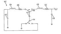
- FIG. 4 ( a )shows a first embodiment of the invention in which a switched capacitor 412 is arranged in a positive-output boost converter configuration (discussed below in more detail). This configuration is used to step up the voltage level of source 402 while preserving the polarity of the input DC power source (e.g., +5V input is stepped up to +9V output).
- the present inventionis not limited to boost converters or non-inverting converters.
- FIG. 4 ( b )shows a second embodiment of the invention in which a switched capacitor is arranged in a negative output (inverting) buck converter configuration in which the output voltage is lesser in magnitude and reversed in polarity (e.g., +5V input is stepped down and inverted to ⁇ 3.3V output relative to the voltage level of DC source 402 ).
- the switched capacitor design common to all embodiments of the present inventioncan also be used in other configurations allowing any combination of voltage level and polarity output relative to a voltage level and polarity of a DC source.
- DC power source 402is connected through an inductor 404 having an associated inductive resistance 406 to one pole of switch 408 .
- Switch 408connects inductor 404 to capacitor 412 or alternately connects capacitor 412 to an output filter including inductor 418 having an associated resistance 422 and, between resistance 422 and ground, capacitor 424 .
- Switch 414connects the opposite plate of capacitor 412 to ground or alternately to DC power source 402 .
- Switches 408 and 414alternate between states at a frequency of about 100 MHz or more.
- the output voltage V outis the potential difference across the capacitor 424 and is used to power an external electronic component.
- the capacitor 412is charged through inductor 404 and associated resistance 406 by DC power source 402 when switches 408 and 414 are set to connect these components through to ground potential in the manner illustrated in FIG. 4 ( a ). Thereafter, switches 408 and 414 change to a “transfer” state to connect DC power source 402 directly to the lower plate of capacitor 412 while the upper plate of capacitor 412 is connected to capacitor 424 through inductor 418 and associated resistance 422 , thereby charging capacitor 424 to the output voltage V out .
- the output voltage V outis approximately doubled from the input voltage at DC power source 402 , as the voltage from source 402 adds to the voltage previously stored on capacitor 412 to charge capacitor 424 .
- the inductor 418 , associated resistance 422 and capacitor 424also act as an output filter smoothing out any ripples in the output voltage V out .
- switches 408 and 414are set to change states when the inductor 404 current reaches zero and the voltage across the capacitor 412 is at a maximum, no stored energy will be lost in the inductor 404 .
- a low-inductance inductor of approximately 100 nHcan be used for inductor 404 with high frequency switches 408 , 414 operating at 100 MHz or more to minimize energy loss and improve the efficiency of the converter.
- FIG. 4 ( b )shows a schematic diagram of a negative output DC converter 450 .
- DC power source 402is connected through inductor 404 having associated resistance 406 to one pole of switch 432 .
- An upper plate of capacitor 412is also connected to switch 432 and the lower plate is connected to switch 434 .
- Switch 432connects inductor 404 to capacitor 412 or alternately connects capacitor 412 to ground.
- Switch 434connects the capacitor 412 to ground or alternately connects capacitor 412 to an output filter including an inductor 418 , associated resistance 422 and a capacitor 438 .
- Capacitor 438is connected between resistance 422 and ground.
- the output voltage V outis the potential difference across the capacitor 438 and is used to power an external electronic component.
- the negative output DC converter 450 shown in FIG. 4 ( b )operates to produce an output voltage V out reversed in polarity relative to the voltage of the input DC source 402 .
- capacitor 412is charged through the inductor 404 and associated resistance 406 by DC power source 402 when switches 432 and 434 are set to connect these components through to a ground potential. Thereafter, switches 432 and 434 change to a transfer state to connect the upper plate of capacitor 412 directly to a ground potential and the lower plate of capacitor 412 to the output filter including capacitor 438 , inductor 418 and associated resistance 422 . This causes capacitor 438 to charge to a voltage which is opposite in polarity to the source voltage 402 , i.e.
- the output voltage V outsmoothed by the output filter, is thus reversed in polarity from the input voltage to the converter from source 402 .
- the frequency of the switches 432 , 434is set according to the inductance value of the inductor 404 to minimize energy loss and improve efficiency.
- the switches 408 and 414 in FIG. 4 ( a ) and switches 432 and 434 in FIG. 4 ( b )change states in response to external clock signals generated by an external controller which is analogous to the control circuit 14 in the conventional boost converter 30 shown in FIG. 1 ( c ).
- the clock signalsare sent to each switch periodically in accordance with a clock frequency of a constant value.
- the inductance value of the inductors 404 , 418 required in the present inventionis significantly lower than conventional converters which generally operate at a lower frequency. Inductance values on the order of micro Henrys (1 ⁇ 10 ⁇ 6 H) or higher are required for conventional forward, buck, or boost converters. Such large inductors and/or transformers (for forward converters) are not compatible with CMOS integrated circuit processing. However, due to its high frequency operation, the present invention requires inductance values on the order of 100 nH (100 ⁇ 10 ⁇ 9 H), a difference of a factor often, which may be fabricated directly on a CMOS integrated circuit.
- FIGS. 5 and 6show schematic diagrams of two different specific implementations of the positive output converter depicted in FIG. 4 ( a ).
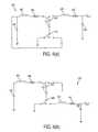
- FIG. 5shows a DC to DC converter 500 which is essentially the same as that depicted in FIG. 4 ( a ), but with transistors 458 , 462 , 464 , 466 used as the switches 408 , 414 of FIG. 4 ( a ).
- Switches 458 , 462 , 464 , and 466change states according to a three component clocking scheme represented by clock signals ⁇ 1 , ⁇ 2 , ⁇ 3 , the timing of which is shown in FIG. 10 .
- the implementation shown in FIG. 5requires multiple clocks, increasing circuit complexity and consuming circuit power, hence reducing the efficiency of the converter.
- Diode 456is a clamping diode which provides a closed path for any residual currents in inductor 404 and prevents large negative voltages at the switch 458 when the switch 458 turns off. Also, if the inductors 404 and 418 are integrated inductors, such as those illustrated in FIGS. 3 ( a )-( e ), the entire converter 500 shown in FIG. 5 may be fabricated on a single integrated circuit chip.
- FIG. 6shows a modification of the output DC boost converter of FIG. 5, where switches 458 and 462 of FIG. 5 have been replaced with diodes 472 and 474 .
- Diodesare simpler devices than transistors, requiring no clock input, and thus dissipate minimal energy.
- a voltage dropoccurs across all diodes, robbing the circuit of some efficiency.
- a voltage drop of 0.7Vis assumed to occur across each integrated circuit diode 472 , 474 .
- Diode 456provides a closed path for any residual inductor currents and prevents large negative voltages at switch 472 . Also, if the inductors 404 and 418 are integrated inductors, such as those illustrated in FIGS. 3 ( a )-( e ), the entire converter 600 shown in FIG. 6 may be fabricated on a single integrated circuit chip.
- FIG. 7shows a negative output DC converter 700 similar to that depicted in FIG. 4 ( b ), described above, with transistors 484 , 485 , 486 and 487 used as switches.
- Switches 484 , 485 , 486 and 487change states according to a clocking scheme represented by clock signals ⁇ 1 , ⁇ 2 , ⁇ 3 , the timing of which is shown in FIG. 10 .
- DC power source 402charges capacitor 412 through inductor 404 during the charging phase, and capacitor 438 is charged through inductor 418 to output voltage V out during the transfer phase.
- Diode 456provides a closed path for any residual inductor currents and prevents large negative voltages at switch 484 .
- the entire converter 700requires multiple clocks with clocking scheme shown in FIG. 10, increasing circuit complexity and consuming circuit power, hence somewhat reducing the efficiency of the converter. If the inductors 404 and 418 are integrated inductors, such as those illustrated in FIGS. 3 ( a )-( e ), the entire converter 700 may be fabricated on a single integrated circuit chip.
- FIG. 8shows a modification of the DC to DC converter of FIG. 7, where switches 485 and 487 of FIG. 7 have been replaced with diodes 488 and 492 .
- Diodesare simpler devices than transistors, requiring no clock input, and thus dissipate minimal energy. However, a voltage drop occurs across all diodes, robbing the circuit of some efficiency. For the present invention, a voltage drop of 0.7V is assumed to occur across each diode 488 , 492 .
- Diode 456provides a closed path for any residual inductor currents and prevents large negative voltages at switch 489 .
- the converter 800 shown in FIG. 8, however,is less complex and does not require multiple clocks to generate extra clock signals.
- the inductors 404 and 418are integrated inductors, such as those illustrated in FIGS. 3 ( a )-( e ), the entire converter 800 shown in FIG. 8 may be fabricated on a single integrated circuit chip.
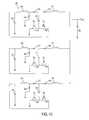
- FIG. 12Another embodiment of the present invention, illustrated in FIG. 12, provides reduced fluctuations in the power supply output voltage (ripple voltage) when several DC converter circuits (constructed as described above) are used in parallel to charge a single capacitor.
- a plurality (three shown) of DC converters 600 of FIG. 6could be connected in parallel, as shown in FIG. 12, each containing all of the components of converter 600 except for the output capacitor 926 and ground.
- the clocking scheme of the switchesmust be coordinated as shown in FIG. 13, i.e. the first parallel circuit is clocked by ⁇ 4 , the second parallel circuit is clocked by ⁇ 5 , and the third parallel circuit is clocked by ⁇ 6 , as shown in FIG. 12 .
- each circuitcharges output capacitor 926 at different time periods, thus reducing voltage fluctuations (ripple voltage) at the output V out .
- FIGS. 3 ( a ) and 3 ( b )show a first integrated circuit inductor which may be used for inductors 404 , 418 in the present invention
- FIGS. 3 ( c ) and 3 ( d )show a second integrated circuit inductor which may be used in the present invention
- FIG. 3 ( e )shows an alternate embodiment of the second integrated circuit inductor of FIGS. 3 ( c ) and 3 ( d ).
- these IC inductorswhich can be directly fabricated in an IC chip, offer additional space and power density advantages over discrete inductors externally mounted to an IC chip.
- FIG. 3 ( a )shows an exploded perspective view of a first integrated inductor formed from a solenoidal inductor pattern 100 .
- Solenoidal pattern 100is made up of three vertically stacked open conductive patterns 103 , 106 and 109 coupled together by conductive segments 112 and 115 .
- each of the three open conductive patterns 103 , 106 , 109is an open rectangle.
- the present inventionis not limited to a particular open pattern shape. Any shape or shapes that can be combined to form a device in which the voltage across the device is proportional to the derivative of the current passing through the device is suitable for use in connection with the present invention.
- Open conductive patterns 103 , 106 and 109are fabricated from a conductive material.
- open conductive patterns 103 , 106 and 109are fabricated from copper.
- theyarc formed from gold, aluminum, silver, or an alloy of copper, gold, aluminum, or silver, or any combination of metals or alloys capable of conducting electric current.
- open conductive patterns 103 , 106 and 109each have a cross-sectional area which varies directly with the current-carrying capacity and varies inversely with the resistance. In other words, as the cross-sectional area decreases, the resistance increases and the current carrying capacity of the open conductive patterns 103 , 106 , and 109 decreases.
- the cross sectional area of each pattern 103 , 106 , 109is selected to ensure that it is capable of carrying the anticipated operating current.
- open conductive pattern 103is coupled to open conductive pattern 106 by conductive segment 112 , which is perpendicular to both open conductive patterns 103 and 106 .
- open conductive patterns 106 and 109are coupled by conductive segment 115 , which is perpendicular to both open conductive patterns 106 and 109 .
- Each of the open conductive patterns 103 , 106 , and 109 shown in FIG. 3 ( a )can be fabricated from a different material.
- open conductive pattern 103can be fabricated from aluminum
- pattern 106can be fabricated from copper
- pattern 109from gold. This provides some flexibility for the inductor designer to control inductor characteristics, such as controlling heat generation by incorporating higher conductivity material into specific sections of the inductor.
- the designeris able to control the location of particular materials to limit impurity migration, such as to avoid the incorporation of a barrier layer to protect a substrate from copper migration by instead locating any copper sufficiently far from the substrate.
- FIG. 3 ( b )shows a side view of a cross-sectional slice of solenoid inductor 100 fabricated on a substrate 203 .
- the fabricated structure 200includes magnetic material layers 206 , 212 , 221 , 233 , open inductor patterns 103 , 106 , 109 , and conductive segments 112 , 115 .
- Each of the layers, patterns and/or segmentsmay be produced by chemical vapor deposition (CVD) or other processes for metallization, metal layering, and/or etching as is known in the art.
- Substrate 203is preferably a semiconductor, such as silicon.
- substrate 203is gallium arsenide, germanium, or some other substrate material suitable for use in the manufacturing of integrated circuits.
- FIGS. 3 ( c ) and 3 ( d )depict a second integrated inductor with square spiral inductor pattern 140 which may be used as inductor 404 , 418 in the invention.
- a first integrated inductor with a square spiral pattern 140is shown in FIG. 3 ( c ).
- the pattern 140need not be limited to a square spiral, but may instead be a circular spiral, polygonal spiral, or any contiguous open pattern fabricated from a conductive material.
- the square spiral inductor pattern 140is preferred because it is easy to manufacture.
- Pattern 140is also preferably fabricated from a high-conductivity material such as copper, but may alternatively be formed from other conducting materials, such as gold, aluminum, silver, or an alloy of copper, gold, aluminum, or silver, or any combination of metals or alloys capable of conducting electric current.
- a high-conductivity materialsuch as copper
- other conducting materialssuch as gold, aluminum, silver, or an alloy of copper, gold, aluminum, or silver, or any combination of metals or alloys capable of conducting electric current.
- FIG. 3 ( d )shows a fragmentary vertical cross-sectional view of a second integrated inductor structure 300 using the square spiral inductor pattern 140 .
- the square spiral inductor pattern 140 of FIG. 3 ( c )is included in the integrated inductor structure 300 as the square cross-sectional areas 230 in FIG. 3 ( d ).
- integrated inductor structure 300is coupled to conducting path 220 through vias 240 to peripheral connection 210 .
- Inductor structure 300is composed of several layers fabricated on substrate 302 and includes magnetic material layer 304 , insulating layer 306 , inductor pattern 230 , second insulating layer 308 , and second magnetic material layer 312 . Each layer is formed on the layer below it through deposition or other processes known in the art.
- Insulating layers 306 and 308may be formed from inorganic silicon oxide film, silicon dioxide, or other inorganic insulating materials known in the art. In alternate embodiments designed for a low temperature processing environment, insulating layers 306 and 308 may be organic insulators, such as parylene and polyimide.
- Substrate 302is preferably a semiconductor, such as silicon.
- substrate 302is gallium arsenide, germanium, or some other substrate material suitable for use in the manufacturing of integrated circuits.
- Inductors intended for use in circuits fabricated on a silicon substrateusually operate at a slightly lower frequency, hence requiring slightly larger inductance values, than inductors intended for use in circuits fabricated on a gallium arsenide substrate.
- a larger inductance valueis usually realized in silicon by having the inductor occupy a larger surface area. Rather than increasing the inductance value by occupying a larger surface area, a larger inductance value is here achieved by adding layers of magnetic material 304 and 312 to the inductor. Magnetic material layers 304 and 312 allow the inductor to store a larger amount of energy in a smaller space, increasing the inductance value.
- Magnetic material layers 304 and 312may be formed from a magnetic material selected according to the inductance requirement.
- a high permeability ferromagnetic materialsuch as pure iron or a NiFe alloy is selected.
- a high permeability alloyis an alloy of 81% Ni and 19% Fe.
- Electrically non-conducting films, such as a magnetic oxide film,may also be suitable for use in the present invention.
- the thickness of the magnetic material layers 304 and 312 and the magnetic properties of the magnetic materialdefine the inductance value of the inductor structure 300 .
- magnetic material layers 304 and 312confine the magnetic flux and noise radiated by current flowing in inductor pattern 230 to the area bounded by the outer surfaces of layers 304 and 312 .
- Double inductor structure 301includes base structure 305 , first sandwich structure 310 , second sandwich structure 315 , and conducting path 320 .
- Base structure 305includes substrate 325 , magnetic material layer 330 , and insulating layer 335 .
- Sandwich structure 310includes inductor pattern 340 , insulating layer 345 , magnetic material layer 350 , and insulating layer 355 .
- Second sandwich structure 315includes inductor pattern 360 , insulating layer 365 , magnetic material layer 370 , and insulating layer 375 .
- Conducting path 320couples sandwich structure 310 to second sandwich structure 315 , and serially connects inductor pattern 340 to inductor pattern 360 .
- a current flowing in the serially connected inductor patternscreates a reinforcing magnetic field in magnetic material layer 350 .
- Magnetic material layers 330 and 370are located below inductor pattern 340 and above inductor pattern 360 , respectively. Magnetic material layers 330 and 370 confine the magnetic flux and noise radiated by a current flowing in inductor patterns 340 and 360 to the area bounded by the outer surfaces of magnetic material layers 330 and 370 .
- FIG. 9illustrates a processor-based system 90 , e.g. a computer system, which utilizes the DC—DC converter of the present invention.
- the processor-based system 90comprises a processor 94 , a memory circuit 96 , and an input/output (I/O) device 92 .
- I/Oinput/output
- One or more of the components of the processor-based system 90for example, one or more of the processor 94 and memory circuit 96 , also includes a DC power source 97 connected to a ground potential and to a DC to DC converter 98 constructed in accordance with the present invention (see FIGS. 4-8 and 12 ).
- the memory circuit 96contains one or more of a random access memory (RAM), for example a DRAM, SRAM, SDRAM, or other type of RAM known in the art, or a read only memory (ROM), for example an EPROM, and EEPROM, flash memory, or other type of ROM known in the art.
- RAMrandom access memory
- ROMread only memory
- the processor 94may be an embedded-memory processor in which the memory circuit 96 is included on the same IC chip as the processor 94 .
- the DC to DC converter 98may also be included on the same IC chip as either or both of the processor 94 and memory circuit 96 .
- the present inventionprovides a DC—DC converter with inductive current limiters to improve efficiency as well as conserve valuable space using integrated components, including integrated inductors. These improvements remove the need for bulky conventional inductors and improve power densities and thermal properties of the resulting device while simplifying the circuit and allowing higher output currents, which can be used, for example, for EEPROM reprogramming. Low voltage and low power consumption of the converter permits its implementation in battery-powered portable electronics.
Landscapes
- Engineering & Computer Science (AREA)
- Power Engineering (AREA)
- Dc-Dc Converters (AREA)
Abstract
Description
Claims (108)
Priority Applications (1)
| Application Number | Priority Date | Filing Date | Title |
|---|---|---|---|
| US09/502,827US6429632B1 (en) | 2000-02-11 | 2000-02-11 | Efficient CMOS DC-DC converters based on switched capacitor power supplies with inductive current limiters |
Applications Claiming Priority (1)
| Application Number | Priority Date | Filing Date | Title |
|---|---|---|---|
| US09/502,827US6429632B1 (en) | 2000-02-11 | 2000-02-11 | Efficient CMOS DC-DC converters based on switched capacitor power supplies with inductive current limiters |
Publications (1)
| Publication Number | Publication Date |
|---|---|
| US6429632B1true US6429632B1 (en) | 2002-08-06 |
Family
ID=23999584
Family Applications (1)
| Application Number | Title | Priority Date | Filing Date |
|---|---|---|---|
| US09/502,827Expired - LifetimeUS6429632B1 (en) | 2000-02-11 | 2000-02-11 | Efficient CMOS DC-DC converters based on switched capacitor power supplies with inductive current limiters |
Country Status (1)
| Country | Link |
|---|---|
| US (1) | US6429632B1 (en) |
Cited By (98)
| Publication number | Priority date | Publication date | Assignee | Title |
|---|---|---|---|---|
| US20020143509A1 (en)* | 2001-03-28 | 2002-10-03 | Gauthier Claude R. | Low-complexity, high accuracy model of a CPU anti-resonance system |
| US20030210023A1 (en)* | 2002-05-10 | 2003-11-13 | Satoru Kurotsu | Power circuit |
| US6653196B2 (en)* | 1999-02-26 | 2003-11-25 | Micron Technology, Inc. | Open pattern inductor |
| US20040222773A1 (en)* | 2003-05-05 | 2004-11-11 | Gardner Donald S. | Fully integrated DC-to-DC regulator utilizing on-chip inductors with high frequency magnetic materials |
| US20050052220A1 (en)* | 2003-09-08 | 2005-03-10 | Burgener Mark L. | Low noise charge pump method and apparatus |
| US20050193358A1 (en)* | 2002-12-13 | 2005-09-01 | Xilinx, Inc. | Reconfiguration of a programmable logic device using internal control |
| US20050213280A1 (en)* | 2004-03-25 | 2005-09-29 | Integral Wave Technologies, Inc. | Trench capacitor power supply system and method |
| US20060010333A1 (en)* | 2004-07-09 | 2006-01-12 | Sean Rhodes | Multi-output power supply device for power sequencing |
| US20060091871A1 (en)* | 2002-05-24 | 2006-05-04 | Siamak Abedinpour | Integrated zvs synchronous buck dc-dc converter with adaptive control |
| US20060101295A1 (en)* | 2004-11-08 | 2006-05-11 | Samsung Electronics Co., Ltd. | Computer for decreasing noise and a control method and medium for decreasing noise thereof |
| US20060133121A1 (en)* | 2003-06-11 | 2006-06-22 | Koninklijke Philips Electronics N.V. | Control system for a voltage converter |
| US20060153495A1 (en)* | 2004-12-06 | 2006-07-13 | John Wynne | Galvanically isolated signal conditioning system |
| US20060177013A1 (en)* | 2005-02-07 | 2006-08-10 | Heine Frifeldt | Form-based user interface for controlling messaging |
| US7102339B1 (en) | 2003-01-21 | 2006-09-05 | Microsemi, Inc. | Method and apparatus to switch operating modes in a PFM converter |
| US7102340B1 (en) | 2003-01-21 | 2006-09-05 | Microsemi Corporation | Dual-mode PFM boost converter |
| US20060280655A1 (en)* | 2005-06-08 | 2006-12-14 | California Institute Of Technology | Intravascular diagnostic and therapeutic sampling device |
| US7190210B2 (en) | 2004-03-25 | 2007-03-13 | Integral Wave Technologies, Inc. | Switched-capacitor power supply system and method |
| US20070183174A1 (en)* | 2006-01-27 | 2007-08-09 | International Rectifier Corporation | High voltage gate driver ic (hvic) with internal charge pumping voltage source |
| US20080001659A1 (en)* | 2006-06-30 | 2008-01-03 | Nokia Corporation | Passive amplification of signals |
| US20080003971A1 (en)* | 2006-06-30 | 2008-01-03 | Nokia Corporation | Multi-function passive frequency mixer |
| US20080003973A1 (en)* | 2006-06-30 | 2008-01-03 | Nokia Corporation | Multi-function passive frequency mixer |
| US7414460B1 (en) | 2006-03-31 | 2008-08-19 | Integrated Device Technology, Inc. | System and method for integrated circuit charge recycling |
| WO2009074820A1 (en)* | 2007-12-13 | 2009-06-18 | University Court Of The University Of Aberdeen | Power converter |
| US20090160422A1 (en)* | 2007-12-20 | 2009-06-25 | Microsemi Corporation | Boost converter with adaptive coil peak current |
| US20090230934A1 (en)* | 2008-03-12 | 2009-09-17 | Sony Ericsson Mobile Communications Ab | Switched mode voltage converter with low-current mode and methods of performing voltage conversion with low-current mode |
| US20100033226A1 (en)* | 2008-07-18 | 2010-02-11 | Tae Youn Kim | Level shifter with output spike reduction |
| US20100052565A1 (en)* | 2008-08-29 | 2010-03-04 | Toshiba Lighting & Technology Corporation | Led lighting device and lighting equipment |
| WO2010029345A1 (en)* | 2008-09-09 | 2010-03-18 | University Court Of The University Of Aberdeen | Power converter |
| US20100211132A1 (en)* | 2009-02-17 | 2010-08-19 | Boston Scientific Neuromodulation Corporation | Selectable Boost Converter and Charge Pump for Compliance Voltage Generation in an Implantable Stimulator Device |
| CN101882869A (en)* | 2010-06-21 | 2010-11-10 | 华南理工大学 | High Gain Boost Converter with LC Switching Network |
| US20110018618A1 (en)* | 2009-07-22 | 2011-01-27 | Green Solution Technology Co., Ltd. | Charge pump circuit |
| US20110101789A1 (en)* | 2008-12-01 | 2011-05-05 | Salter Jr Thomas Steven | Rf power harvesting circuit |
| US20110238203A1 (en)* | 2010-03-23 | 2011-09-29 | Qualcomm Incorporated | Method and Apparatus to Provide a Clock Signal to a Charge Pump |
| EP2448099A1 (en)* | 2010-10-28 | 2012-05-02 | Flextronics International Kft. | Voltage converter |
| US20120105026A1 (en)* | 2010-10-29 | 2012-05-03 | Hsiang-Yu Lee | Safe electric power regulating circuit |
| US20120199172A1 (en)* | 2010-03-15 | 2012-08-09 | Tigo Energy, Inc. | Systems and Methods to Provide Enhanced Diode Bypass Paths |
| US20120261767A1 (en)* | 2011-04-14 | 2012-10-18 | Intersil Americas Inc. | Method and structure for reducing gate leakage current and positive bias temperature instability drift |
| US8362813B2 (en) | 2011-03-24 | 2013-01-29 | Pericom Semiconductor Corp. | Re-driver with pre-emphasis injected through a transformer and tuned by an L-C tank |
| US20130038305A1 (en)* | 2010-04-28 | 2013-02-14 | St-Ericsson Sa | Direct Current Voltage Conversion Circuit |
| US8536636B2 (en) | 2007-04-26 | 2013-09-17 | Peregrine Semiconductor Corporation | Tuning capacitance to enhance FET stack voltage withstand |
| US8559907B2 (en) | 2004-06-23 | 2013-10-15 | Peregrine Semiconductor Corporation | Integrated RF front end with stacked transistor switch |
| US8583111B2 (en) | 2001-10-10 | 2013-11-12 | Peregrine Semiconductor Corporation | Switch circuit and method of switching radio frequency signals |
| US8669804B2 (en) | 2008-02-28 | 2014-03-11 | Peregrine Semiconductor Corporation | Devices and methods for improving voltage handling and/or bi-directionality of stacks of elements when connected between terminals |
| US8686787B2 (en) | 2011-05-11 | 2014-04-01 | Peregrine Semiconductor Corporation | High voltage ring pump with inverter stages and voltage boosting stages |
| WO2012125339A3 (en)* | 2011-03-16 | 2014-04-24 | Deere & Company | System for controlling rotary electric machines to reduce current ripple on direct current bus |
| US8742502B2 (en) | 2005-07-11 | 2014-06-03 | Peregrine Semiconductor Corporation | Method and apparatus for use in improving linearity of MOSFETs using an accumulated charge sink-harmonic wrinkle reduction |
| US20140266109A1 (en)* | 2013-03-14 | 2014-09-18 | Cirrus Logic, Inc. | Systems and methods for reducing voltage ringing in a power converter |
| US8954902B2 (en) | 2005-07-11 | 2015-02-10 | Peregrine Semiconductor Corporation | Method and apparatus improving gate oxide reliability by controlling accumulated charge |
| US8994452B2 (en) | 2008-07-18 | 2015-03-31 | Peregrine Semiconductor Corporation | Low-noise high efficiency bias generation circuits and method |
| US9035627B2 (en) | 2012-06-13 | 2015-05-19 | Intel Mobile Communications GmbH | Switched mode power supply employing first and second feedback signals and a method of operating thereof |
| US9048730B2 (en) | 2012-06-13 | 2015-06-02 | Intel Mobile Communications GmbH | Switched mode power supply and a method for operating a switched mode power supply |
| US9118241B2 (en)* | 2012-06-13 | 2015-08-25 | Intel Deutschland Gmbh | Switched-mode power supply and a two-phase DC to DC converter having switches and a filter that deliver current from a node among converter stages |
| US9130564B2 (en) | 2005-07-11 | 2015-09-08 | Peregrine Semiconductor Corporation | Method and apparatus for use in improving linearity of MOSFETs using an accumulated charge sink |
| US9264053B2 (en) | 2011-01-18 | 2016-02-16 | Peregrine Semiconductor Corporation | Variable frequency charge pump |
| US9312761B2 (en) | 2014-02-12 | 2016-04-12 | International Business Machines Corporation | Three-D power converter in three distinct strata |
| US9324885B2 (en) | 2009-10-02 | 2016-04-26 | Tigo Energy, Inc. | Systems and methods to provide enhanced diode bypass paths |
| US9385607B2 (en) | 2010-10-29 | 2016-07-05 | Superc-Touch Corporation | Safe electric power regulating circuit |
| US9419565B2 (en) | 2013-03-14 | 2016-08-16 | Peregrine Semiconductor Corporation | Hot carrier injection compensation |
| US9543842B2 (en) | 2011-06-23 | 2017-01-10 | University Court Of The University Of Aberdeen | Converter for transferring power between DC systems |
| US20170047914A1 (en)* | 2015-08-12 | 2017-02-16 | International Business Machines Corporation | Pulse generator with switched capacitors |
| FR3040113A1 (en)* | 2015-08-10 | 2017-02-17 | Commissariat Energie Atomique | DC-DC CONVERTER |
| US9590674B2 (en) | 2012-12-14 | 2017-03-07 | Peregrine Semiconductor Corporation | Semiconductor devices with switchable ground-body connection |
| US9660590B2 (en) | 2008-07-18 | 2017-05-23 | Peregrine Semiconductor Corporation | Low-noise high efficiency bias generation circuits and method |
| US9680374B2 (en) | 2014-05-27 | 2017-06-13 | Marcus Allen Smith | DC to DC boost converter utilizing storage capacitors charged by parallel inductor |
| US20170184639A1 (en)* | 2015-12-23 | 2017-06-29 | Intel IP Corporation | Apparatuses, methods, and systems for detection of a current level |
| WO2017196826A1 (en)* | 2016-05-09 | 2017-11-16 | Peregrine Semiconductor Corporation | Power converter |
| US9831857B2 (en) | 2015-03-11 | 2017-11-28 | Peregrine Semiconductor Corporation | Power splitter with programmable output phase shift |
| DE102016217040A1 (en) | 2016-09-07 | 2018-03-08 | Brusa Elektronik Ag | High performance charge pump with inductive elements |
| US9948281B2 (en) | 2016-09-02 | 2018-04-17 | Peregrine Semiconductor Corporation | Positive logic digitally tunable capacitor |
| US10063149B2 (en) | 2016-11-23 | 2018-08-28 | Apple Inc. | Multi-phase switching power converter module stack |
| US10236872B1 (en) | 2018-03-28 | 2019-03-19 | Psemi Corporation | AC coupling modules for bias ladders |
| US20190372454A1 (en)* | 2017-12-20 | 2019-12-05 | Infineon Technologies Austria Ag | Switched Capacitor Converter Topology Using a Compensation Inductor for Charge Transfer |
| US10505530B2 (en) | 2018-03-28 | 2019-12-10 | Psemi Corporation | Positive logic switch with selectable DC blocking circuit |
| WO2020036687A1 (en)* | 2018-08-13 | 2020-02-20 | Intel Corporation | Multi-terminal inductors for voltage regulators |
| US10680512B2 (en) | 2017-07-19 | 2020-06-09 | Infineon Technologies Austria Ag | Switched-capacitor converters with capacitor pre-charging |
| US10693367B1 (en)* | 2019-02-19 | 2020-06-23 | Rolls-Royce North American Technologies, Inc. | Pre-charging circuit for power converters |
| US10804892B2 (en) | 2005-07-11 | 2020-10-13 | Psemi Corporation | Circuit and method for controlling charge injection in radio frequency switches |
| US10886911B2 (en) | 2018-03-28 | 2021-01-05 | Psemi Corporation | Stacked FET switch bias ladders |
| US10917007B2 (en) | 2011-05-05 | 2021-02-09 | Psemi Corporation | Power converter with modular stages connected by floating terminals |
| US11011633B2 (en) | 2005-07-11 | 2021-05-18 | Psemi Corporation | Method and apparatus for use in improving linearity of MOSFETs using an accumulated charge sink-harmonic wrinkle reduction |
| US11190097B2 (en) | 2019-09-09 | 2021-11-30 | Samsung Electronics Co., Ltd. | Voltage converter |
| US11211861B2 (en) | 2011-05-05 | 2021-12-28 | Psemi Corporation | DC-DC converter with modular stages |
| USRE48965E1 (en) | 2005-07-11 | 2022-03-08 | Psemi Corporation | Method and apparatus improving gate oxide reliability by controlling accumulated charge |
| US11303205B2 (en) | 2011-05-05 | 2022-04-12 | Psemi Corporation | Power converters with modular stages |
| US11316424B2 (en) | 2011-05-05 | 2022-04-26 | Psemi Corporation | Dies with switches for operating a switched-capacitor power converter |
| US11374400B2 (en) | 2020-12-01 | 2022-06-28 | Rolls-Royce Singapore Pte. Ltd. | Topology of a solid state power controller with two mid-capacitors |
| CN114999553A (en)* | 2022-05-06 | 2022-09-02 | 长江先进存储产业创新中心有限责任公司 | Storage system, forming method and control method of storage system |
| US11476849B2 (en) | 2020-01-06 | 2022-10-18 | Psemi Corporation | High power positive logic switch |
| US11502597B2 (en)* | 2020-01-08 | 2022-11-15 | Infineon Technologies Austria Ag | Startup of a voltage converter |
| US20240022164A1 (en)* | 2022-07-18 | 2024-01-18 | Skyworks Solutions, Inc. | Voltage generator with low clock feedthrough |
| US11901817B2 (en) | 2013-03-15 | 2024-02-13 | Psemi Corporation | Protection of switched capacitor power converter |
| US12107495B2 (en) | 2015-07-08 | 2024-10-01 | Psemi Corporation | Switched-capacitor power converters |
| US12176815B2 (en) | 2011-12-19 | 2024-12-24 | Psemi Corporation | Switched-capacitor circuit control in power converters |
| US12212232B2 (en) | 2013-03-15 | 2025-01-28 | Psemi Corporation | Power supply for gate driver in switched-capacitor circuit |
| US12237765B2 (en) | 2015-03-13 | 2025-02-25 | Psemi Corporation | DC-DC transformer with inductor for the facilitation of adiabatic inter-capacitor charge transport |
| USRE50353E1 (en)* | 2018-02-13 | 2025-03-25 | Lion Semiconductor Inc. | Circuits and methods for hybrid 3:1 voltage regulators |
| US12383745B2 (en) | 2019-09-06 | 2025-08-12 | Boston Scientific Neuromodulation Corporation | Management of compliance voltage for a stimulator device |
| US12438135B2 (en) | 2011-10-18 | 2025-10-07 | Psemi Corporation | Multilayer power, converter with devices having reduced lateral current |
Citations (9)
| Publication number | Priority date | Publication date | Assignee | Title |
|---|---|---|---|---|
| US4636930A (en)* | 1985-10-01 | 1987-01-13 | Maxim Integrated Products, Inc. | Integrated dual charge pump power supply and RS-232 transmitter/receiver |
| US4999761A (en) | 1985-10-01 | 1991-03-12 | Maxim Integrated Products | Integrated dual charge pump power supply and RS-232 transmitter/receiver |
| US5396527A (en)* | 1992-07-17 | 1995-03-07 | Massachusetts Institute Of Technology | Recovered energy logic circuits |
| US5400235A (en) | 1992-08-07 | 1995-03-21 | International Business Machines Corp. | High frequency energy saving DC to DC power converter |
| US5485365A (en)* | 1991-01-29 | 1996-01-16 | Dan-Harry; Dawari D. | High frequency, high density power conversion system |
| US5680300A (en) | 1995-12-22 | 1997-10-21 | Analog Devices, Inc. | Regulated charge pump DC/DC converter |
| US5736842A (en)* | 1996-07-11 | 1998-04-07 | Delta Electronics, Inc. | Technique for reducing rectifier reverse-recovery-related losses in high-voltage high power converters |
| US5751561A (en)* | 1995-10-16 | 1998-05-12 | Computer Products, Inc. | Low cost AC-to-DC converter having input current with reduced harmonics |
| US5966298A (en)* | 1996-08-21 | 1999-10-12 | U.S. Philips Corporation | Electrical device with a constant voltage converter |
- 2000
- 2000-02-11USUS09/502,827patent/US6429632B1/ennot_activeExpired - Lifetime
Patent Citations (9)
| Publication number | Priority date | Publication date | Assignee | Title |
|---|---|---|---|---|
| US4636930A (en)* | 1985-10-01 | 1987-01-13 | Maxim Integrated Products, Inc. | Integrated dual charge pump power supply and RS-232 transmitter/receiver |
| US4999761A (en) | 1985-10-01 | 1991-03-12 | Maxim Integrated Products | Integrated dual charge pump power supply and RS-232 transmitter/receiver |
| US5485365A (en)* | 1991-01-29 | 1996-01-16 | Dan-Harry; Dawari D. | High frequency, high density power conversion system |
| US5396527A (en)* | 1992-07-17 | 1995-03-07 | Massachusetts Institute Of Technology | Recovered energy logic circuits |
| US5400235A (en) | 1992-08-07 | 1995-03-21 | International Business Machines Corp. | High frequency energy saving DC to DC power converter |
| US5751561A (en)* | 1995-10-16 | 1998-05-12 | Computer Products, Inc. | Low cost AC-to-DC converter having input current with reduced harmonics |
| US5680300A (en) | 1995-12-22 | 1997-10-21 | Analog Devices, Inc. | Regulated charge pump DC/DC converter |
| US5736842A (en)* | 1996-07-11 | 1998-04-07 | Delta Electronics, Inc. | Technique for reducing rectifier reverse-recovery-related losses in high-voltage high power converters |
| US5966298A (en)* | 1996-08-21 | 1999-10-12 | U.S. Philips Corporation | Electrical device with a constant voltage converter |
Non-Patent Citations (24)
| Title |
|---|
| Acik et al.; "Active Clamped ZVS Forward Converter with Soft-Switched Synchronous Rectifier for Maximum Efficiency Operation"; Proc. of 29th Annual IEEE Power Electronics Specialists Conference, Cat. No. 98CH36196, vol. 2, pp. 1237-1242, 1998, No date. |
| Berkovici et al.; "High Efficient PWM Zero-Voltage-Transition DC-DC Boost Converter"; Proc. of the 1998 IEEE International Symposium on Circuit and Systems, vol. 6, 1998, pp. 442-445, No date. |
| Dias et al.; "An Improved Self-Resonant PWM Forward Converter"; Proc of 13th Annual Power Electronics Conference and Exposition, vol. 2, pp. 620-625, 1998, No Date. |
| Djekic et al.; "High Frequency Synchronous Buck Converter for Low Voltage Applications", Proc. of 29th Annual IEEE Power Electronics Specialists Conference, 1998, pp. 1248-1254, No date. |
| Favrat, et al, "A New High Efficiency CMOS Voltage Doubler", Proc. Of the IEEE 1997 Custom Integrated Circuits Conference, pp. 259-262, 1997, No Date. |
| Favrat, et al., "A High-Efficiency CMOS Voltage Doubler", IEEE J. Solid-State Circuits, vol. 33, No. 3, pp. 410-416, Mar. 1998. |
| Gillingham; "High Speed Charge-Pump"; IBM Technical Disclosure Bulletin, vol. 27, No. 29, Feb. 1985, pp. 5407-5409. |
| Kim et al.; "An Improved Soft Switching Forward DC/DC Converter Using Energy Recovery Snubber"; Proc. of 19th International Telecommunications Energy Conference, 1997, pp. 46-49, No date. |
| Martino et al.; "An On-Chip Back-Bias Generator for MOS Dynamic Memory"; IEEE Journal of Solid-State Circuits, vol. SC-15, No. 5, Oct. 1980, pp. 820-826. |
| Matsumoto et al.; "Integration of a Power Supply for System-on-Chip"; IEICE Trans. Fundamentals, vol. E80-A, No. 2, Feb. 1997, pp. 276-282. |
| Matsuo et al.; "A Novel Soft-Switching Buck-Boost Type AC-DC Converter with High Power Efficiency, High Power Factor and Low Harmonic Distortion"; Proc. of 29th Annual IEEE Power Electronics Specialists Conference, vol. 2, 1998, pp. 1030-1035, No Date. |
| Mino et al.; "A Compact Buck-Converter Using a Thin-Film Inductor"; IEEE Power Electronics Conference and Expo., vol. 1, Part 1, Mar. 1996, pp. 422-426. |
| Mino et al.; "Switching Converter Using Thin-Film Microtransformer with Monolithically Integrated Rectifier Diodes"; IEICE Trans. Electron., vol. E80-C, No. 6, Jun. 1997; pp. 821-827. |
| Monna, et al, "Charge Pump For Optimal Dynamic Range Filters", Proc. of 1994 IEEE Int. Symposium on Circuits and Systems, vol. 5, pp. 747-750, 1994, No Date. |
| Moore; "Buck Regulator Answers Portable Challenges"; Electronic Design, vol. 46, No. 20, Sep. 1, 1998; pp. 128-134. |
| Moore; "Regulator topologies standardize battery powered systems"; Electronic Design News (European Edition); vol. 39, No. 2, pp. 59-64, Jan., 20, 1994. |
| Sherman; "DC-DC conversion techniques for noise-sensitive applications"; Electronic Design, vol. 45, Nov. 17, 1997, 7 total pages. |
| Shoyama et al.; "Voltage Resonant Buck-Boost Converter Using Multi-Layer-Winding Transformer"; Record of 20th Annual IEEE Power Electronics Specialists Conference, vol. 2, 1989, pp. 895-901, No date. |
| Sun et al.; "Forward Converter Regulator Using PWM Controlled Transformer"; Proc. of the IEEE Power Electronics Specialists Conference, 1993, pp. 1116-1122, No Date. |
| Tanzawa et al.; "A Quick Boosting Charge Pump Circuit for High Density and Low Voltage Flash Memories", 1994 Symposium on VLSI Circuits Digest of Technical Papers, pp. 65 and 66, No Date. |
| Tsukamoto et al.; "A Highly Efficient Buck Converter with Double-Anti-Crossover Synchronous Rectification Using a Newly Developed Control IC"; Proc. of 29th Annual IEEE Power Electronics Specialists Conference, 1998, pp. 1243-1247, No Date. |
| Wang, et al, "Efficiency Improvement In Charge Pump Circuits", IEEE Journal of Solid-State Circuits, vol. 32, No. 6, pp. 852-860, 1997, No Date. |
| Xi et al.; "A Zero Voltage Switching Forward Converter Topology"; Proc. of 19th International Telecommunications Energy Conference, 1997, pp. 116-123, No Date. |
| Yoon, et al, "Charge pump boosting technique for power noise immune high-speed PLL implementation", Electronics Letters, vol. 34, No. 15, pp. 1445-1446, Jul. 1998. |
Cited By (201)
| Publication number | Priority date | Publication date | Assignee | Title |
|---|---|---|---|---|
| US9929229B2 (en) | 1999-02-26 | 2018-03-27 | Micron Technology, Inc. | Process of manufacturing an open pattern inductor |
| US7091575B2 (en) | 1999-02-26 | 2006-08-15 | Micron Technology, Inc. | Open pattern inductor |
| US6653196B2 (en)* | 1999-02-26 | 2003-11-25 | Micron Technology, Inc. | Open pattern inductor |
| US20040103522A1 (en)* | 1999-02-26 | 2004-06-03 | Micron Technology, Inc. | Open pattern inductor |
| US7262482B2 (en) | 1999-02-26 | 2007-08-28 | Micron Technology, Inc. | Open pattern inductor |
| US7380328B2 (en) | 1999-02-26 | 2008-06-03 | Micron Technology, Inc. | Method of forming an inductor |
| US20080246578A1 (en)* | 1999-02-26 | 2008-10-09 | Micron Technology Inc. | Open pattern inductor |
| US20060012007A1 (en)* | 1999-02-26 | 2006-01-19 | Micron Technology, Inc. | Open pattern inductor |
| US8009006B2 (en) | 1999-02-26 | 2011-08-30 | Micron Technology, Inc. | Open pattern inductor |
| US6975977B2 (en)* | 2001-03-28 | 2005-12-13 | Sun Microsystems, Inc. | Low-complexity, high accuracy model of a CPU anti-resonance system |
| US20020143509A1 (en)* | 2001-03-28 | 2002-10-03 | Gauthier Claude R. | Low-complexity, high accuracy model of a CPU anti-resonance system |
| US10797694B2 (en) | 2001-10-10 | 2020-10-06 | Psemi Corporation | Switch circuit and method of switching radio frequency signals |
| US10812068B2 (en) | 2001-10-10 | 2020-10-20 | Psemi Corporation | Switch circuit and method of switching radio frequency signals |
| US9225378B2 (en) | 2001-10-10 | 2015-12-29 | Peregrine Semiconductor Corpopration | Switch circuit and method of switching radio frequency signals |
| US8583111B2 (en) | 2001-10-10 | 2013-11-12 | Peregrine Semiconductor Corporation | Switch circuit and method of switching radio frequency signals |
| US20030210023A1 (en)* | 2002-05-10 | 2003-11-13 | Satoru Kurotsu | Power circuit |
| US6801444B2 (en)* | 2002-05-10 | 2004-10-05 | Oki Electric Industry Co., Ltd. | Power circuit |
| US20060091871A1 (en)* | 2002-05-24 | 2006-05-04 | Siamak Abedinpour | Integrated zvs synchronous buck dc-dc converter with adaptive control |
| US7218085B2 (en)* | 2002-05-24 | 2007-05-15 | Arizona Board Of Regents | Integrated ZVS synchronous buck DC-DC converter with adaptive control |
| US20050193358A1 (en)* | 2002-12-13 | 2005-09-01 | Xilinx, Inc. | Reconfiguration of a programmable logic device using internal control |
| US7102339B1 (en) | 2003-01-21 | 2006-09-05 | Microsemi, Inc. | Method and apparatus to switch operating modes in a PFM converter |
| US7102340B1 (en) | 2003-01-21 | 2006-09-05 | Microsemi Corporation | Dual-mode PFM boost converter |
| US20050200338A1 (en)* | 2003-05-05 | 2005-09-15 | Gardner Donald S. | Fully integrated DC-to-DC regulator utilizing on-chip inductors with high frequency magnetic materials |
| WO2004099960A1 (en)* | 2003-05-05 | 2004-11-18 | Intel Corporation | Fully integrated dc-dc converter utilizing on-chip high frequency inductors |
| US20040222773A1 (en)* | 2003-05-05 | 2004-11-11 | Gardner Donald S. | Fully integrated DC-to-DC regulator utilizing on-chip inductors with high frequency magnetic materials |
| US7202648B2 (en)* | 2003-05-05 | 2007-04-10 | Intel Corporation | Fully integrated DC-to-DC regulator utilizing on-chip inductors with high frequency magnetic materials |
| US20060133121A1 (en)* | 2003-06-11 | 2006-06-22 | Koninklijke Philips Electronics N.V. | Control system for a voltage converter |
| US7120038B2 (en)* | 2003-06-11 | 2006-10-10 | Koninklijke Philips Electronics N.V. | Control system for a voltage converter |
| US9190902B2 (en)* | 2003-09-08 | 2015-11-17 | Peregrine Semiconductor Corporation | Low noise charge pump method and apparatus |
| US10965276B2 (en) | 2003-09-08 | 2021-03-30 | Psemi Corporation | Low noise charge pump method and apparatus |
| US20050052220A1 (en)* | 2003-09-08 | 2005-03-10 | Burgener Mark L. | Low noise charge pump method and apparatus |
| US20100214010A1 (en)* | 2003-09-08 | 2010-08-26 | Burgener Mark L | Low noise charge pump method and apparatus |
| US7719343B2 (en)* | 2003-09-08 | 2010-05-18 | Peregrine Semiconductor Corporation | Low noise charge pump method and apparatus |
| US8378736B2 (en) | 2003-09-08 | 2013-02-19 | Peregrine Semiconductor Corporation | Low noise charge pump method and apparatus |
| US20050213280A1 (en)* | 2004-03-25 | 2005-09-29 | Integral Wave Technologies, Inc. | Trench capacitor power supply system and method |
| US7190210B2 (en) | 2004-03-25 | 2007-03-13 | Integral Wave Technologies, Inc. | Switched-capacitor power supply system and method |
| US7239194B2 (en) | 2004-03-25 | 2007-07-03 | Integral Wave Technologies, Inc. | Trench capacitor power supply system and method |
| US8649754B2 (en) | 2004-06-23 | 2014-02-11 | Peregrine Semiconductor Corporation | Integrated RF front end with stacked transistor switch |
| US9369087B2 (en) | 2004-06-23 | 2016-06-14 | Peregrine Semiconductor Corporation | Integrated RF front end with stacked transistor switch |
| US9680416B2 (en) | 2004-06-23 | 2017-06-13 | Peregrine Semiconductor Corporation | Integrated RF front end with stacked transistor switch |
| US8559907B2 (en) | 2004-06-23 | 2013-10-15 | Peregrine Semiconductor Corporation | Integrated RF front end with stacked transistor switch |
| US20060010333A1 (en)* | 2004-07-09 | 2006-01-12 | Sean Rhodes | Multi-output power supply device for power sequencing |
| US7456525B2 (en) | 2004-07-09 | 2008-11-25 | Honeywell International Inc. | Multi-output power supply device for power sequencing |
| US7516338B2 (en)* | 2004-11-08 | 2009-04-07 | Samsung Electronics Co., Ltd. | Method and apparatus for temporarily decreasing an equivalent series resistance to decrease noise during a voltage change |
| US20060101295A1 (en)* | 2004-11-08 | 2006-05-11 | Samsung Electronics Co., Ltd. | Computer for decreasing noise and a control method and medium for decreasing noise thereof |
| WO2006062616A3 (en)* | 2004-12-06 | 2007-03-15 | Analog Devices Inc | Galvanically isolated signal conditioning system |
| US20060153495A1 (en)* | 2004-12-06 | 2006-07-13 | John Wynne | Galvanically isolated signal conditioning system |
| CN101102962B (en)* | 2004-12-06 | 2012-07-18 | 美国亚德诺半导体公司 | Galvanically isolated signal conditioning system |
| JP2008531297A (en)* | 2004-12-06 | 2008-08-14 | アナログ ディヴァイスィズ インク | DC-isolated signal conditioning system |
| US7288940B2 (en)* | 2004-12-06 | 2007-10-30 | Analog Devices, Inc. | Galvanically isolated signal conditioning system |
| US20060177013A1 (en)* | 2005-02-07 | 2006-08-10 | Heine Frifeldt | Form-based user interface for controlling messaging |
| US20110125136A1 (en)* | 2005-06-08 | 2011-05-26 | Morteza Gharib | Intravascular diagnostic and therapeutic sampling device |
| US20060280655A1 (en)* | 2005-06-08 | 2006-12-14 | California Institute Of Technology | Intravascular diagnostic and therapeutic sampling device |
| US10804892B2 (en) | 2005-07-11 | 2020-10-13 | Psemi Corporation | Circuit and method for controlling charge injection in radio frequency switches |
| US8742502B2 (en) | 2005-07-11 | 2014-06-03 | Peregrine Semiconductor Corporation | Method and apparatus for use in improving linearity of MOSFETs using an accumulated charge sink-harmonic wrinkle reduction |
| US11011633B2 (en) | 2005-07-11 | 2021-05-18 | Psemi Corporation | Method and apparatus for use in improving linearity of MOSFETs using an accumulated charge sink-harmonic wrinkle reduction |
| US8954902B2 (en) | 2005-07-11 | 2015-02-10 | Peregrine Semiconductor Corporation | Method and apparatus improving gate oxide reliability by controlling accumulated charge |
| US9087899B2 (en) | 2005-07-11 | 2015-07-21 | Peregrine Semiconductor Corporation | Method and apparatus for use in improving linearity of MOSFETs using an accumulated charge sink-harmonic wrinkle reduction |
| US12074217B2 (en) | 2005-07-11 | 2024-08-27 | Psemi Corporation | Method and apparatus for use in improving linearity of MOSFETs using an accumulated charge sink-harmonic wrinkle reduction |
| USRE48944E1 (en) | 2005-07-11 | 2022-02-22 | Psemi Corporation | Method and apparatus for use in improving linearity of MOSFETS using an accumulated charge sink |
| US9130564B2 (en) | 2005-07-11 | 2015-09-08 | Peregrine Semiconductor Corporation | Method and apparatus for use in improving linearity of MOSFETs using an accumulated charge sink |
| US9608619B2 (en) | 2005-07-11 | 2017-03-28 | Peregrine Semiconductor Corporation | Method and apparatus improving gate oxide reliability by controlling accumulated charge |
| USRE48965E1 (en) | 2005-07-11 | 2022-03-08 | Psemi Corporation | Method and apparatus improving gate oxide reliability by controlling accumulated charge |
| US10797691B1 (en) | 2005-07-11 | 2020-10-06 | Psemi Corporation | Method and apparatus for use in improving linearity of MOSFETs using an accumulated charge sink |
| US20070183174A1 (en)* | 2006-01-27 | 2007-08-09 | International Rectifier Corporation | High voltage gate driver ic (hvic) with internal charge pumping voltage source |
| US8054054B2 (en)* | 2006-01-27 | 2011-11-08 | International Rectifier Corporation | High voltage gate driver IC (HVIC) with internal charge pumping voltage source |
| US7414460B1 (en) | 2006-03-31 | 2008-08-19 | Integrated Device Technology, Inc. | System and method for integrated circuit charge recycling |
| US7630700B2 (en)* | 2006-06-30 | 2009-12-08 | Nokia Corporation | Multi-function passive frequency mixer |
| US7844233B2 (en) | 2006-06-30 | 2010-11-30 | Nokia Corporation | Passive amplification of signals |
| US20080003971A1 (en)* | 2006-06-30 | 2008-01-03 | Nokia Corporation | Multi-function passive frequency mixer |
| US20080003973A1 (en)* | 2006-06-30 | 2008-01-03 | Nokia Corporation | Multi-function passive frequency mixer |
| US7668527B2 (en) | 2006-06-30 | 2010-02-23 | Nokia Corporation | Multi-function passive frequency mixer |
| US20080001659A1 (en)* | 2006-06-30 | 2008-01-03 | Nokia Corporation | Passive amplification of signals |
| US10951210B2 (en) | 2007-04-26 | 2021-03-16 | Psemi Corporation | Tuning capacitance to enhance FET stack voltage withstand |
| US9177737B2 (en) | 2007-04-26 | 2015-11-03 | Peregrine Semiconductor Corporation | Tuning capacitance to enhance FET stack voltage withstand |
| US8536636B2 (en) | 2007-04-26 | 2013-09-17 | Peregrine Semiconductor Corporation | Tuning capacitance to enhance FET stack voltage withstand |
| US20120091979A1 (en)* | 2007-12-13 | 2012-04-19 | University Court Of The University Of Aberdeen | High gain dc transformer |
| WO2009074820A1 (en)* | 2007-12-13 | 2009-06-18 | University Court Of The University Of Aberdeen | Power converter |
| US20090160422A1 (en)* | 2007-12-20 | 2009-06-25 | Microsemi Corporation | Boost converter with adaptive coil peak current |
| US7906943B2 (en) | 2007-12-20 | 2011-03-15 | Microsemi Corporation | Boost converter with adaptive coil peak current |
| US11671091B2 (en) | 2008-02-28 | 2023-06-06 | Psemi Corporation | Devices and methods for improving voltage handling and/or bi-directionality of stacks of elements when connected between terminals |
| US8669804B2 (en) | 2008-02-28 | 2014-03-11 | Peregrine Semiconductor Corporation | Devices and methods for improving voltage handling and/or bi-directionality of stacks of elements when connected between terminals |
| US9106227B2 (en) | 2008-02-28 | 2015-08-11 | Peregrine Semiconductor Corporation | Devices and methods for improving voltage handling and/or bi-directionality of stacks of elements when connected between terminals |
| US11082040B2 (en) | 2008-02-28 | 2021-08-03 | Psemi Corporation | Devices and methods for improving voltage handling and/or bi-directionality of stacks of elements when connected between terminals |
| US9024700B2 (en) | 2008-02-28 | 2015-05-05 | Peregrine Semiconductor Corporation | Method and apparatus for use in digitally tuning a capacitor in an integrated circuit device |
| US12431890B2 (en) | 2008-02-28 | 2025-09-30 | Psemi Corporation | Devices and methods for improving voltage handling and/or bi-directionality of stacks of elements when connected between terminals |
| US9197194B2 (en) | 2008-02-28 | 2015-11-24 | Peregrine Semiconductor Corporation | Methods and apparatuses for use in tuning reactance in a circuit device |
| US9293262B2 (en) | 2008-02-28 | 2016-03-22 | Peregrine Semiconductor Corporation | Digitally tuned capacitors with tapered and reconfigurable quality factors |
| US7928705B2 (en)* | 2008-03-12 | 2011-04-19 | Sony Ericsson Mobile Communications Ab | Switched mode voltage converter with low-current mode and methods of performing voltage conversion with low-current mode |
| US20090230934A1 (en)* | 2008-03-12 | 2009-09-17 | Sony Ericsson Mobile Communications Ab | Switched mode voltage converter with low-current mode and methods of performing voltage conversion with low-current mode |
| US8994452B2 (en) | 2008-07-18 | 2015-03-31 | Peregrine Semiconductor Corporation | Low-noise high efficiency bias generation circuits and method |
| US9030248B2 (en) | 2008-07-18 | 2015-05-12 | Peregrine Semiconductor Corporation | Level shifter with output spike reduction |
| US20100033226A1 (en)* | 2008-07-18 | 2010-02-11 | Tae Youn Kim | Level shifter with output spike reduction |
| US9660590B2 (en) | 2008-07-18 | 2017-05-23 | Peregrine Semiconductor Corporation | Low-noise high efficiency bias generation circuits and method |
| US20100052565A1 (en)* | 2008-08-29 | 2010-03-04 | Toshiba Lighting & Technology Corporation | Led lighting device and lighting equipment |
| EP2160076A3 (en)* | 2008-08-29 | 2011-06-01 | Toshiba Lighting & Technology Corporation | LED lighting device and lighting equipment |
| US8476840B2 (en) | 2008-08-29 | 2013-07-02 | Toshiba Lighting & Technology Corporation | LED lighting device and lighting equipment |
| WO2010029345A1 (en)* | 2008-09-09 | 2010-03-18 | University Court Of The University Of Aberdeen | Power converter |
| US20110101789A1 (en)* | 2008-12-01 | 2011-05-05 | Salter Jr Thomas Steven | Rf power harvesting circuit |
| US20100211132A1 (en)* | 2009-02-17 | 2010-08-19 | Boston Scientific Neuromodulation Corporation | Selectable Boost Converter and Charge Pump for Compliance Voltage Generation in an Implantable Stimulator Device |
| US9872995B2 (en) | 2009-02-17 | 2018-01-23 | Boston Scientific Neuromodulation Corporation | Selectable boost converter and charge pump for compliance voltage generation in an implantable stimulator device |
| US9233254B2 (en)* | 2009-02-17 | 2016-01-12 | Boston Scientific Neuromodulation Corporation | Selectable boost converter and charge pump for compliance voltage generation in an implantable stimulator device |
| US10391324B2 (en) | 2009-02-17 | 2019-08-27 | Boston Scientific Neuromodulation Corporation | Selectable boost converter and charge pump for compliance voltage generation in an implantable stimulator device |
| US20110018618A1 (en)* | 2009-07-22 | 2011-01-27 | Green Solution Technology Co., Ltd. | Charge pump circuit |
| US11201494B2 (en) | 2009-10-02 | 2021-12-14 | Tigo Energy, Inc. | Systems and methods to provide enhanced diode bypass paths |
| US9324885B2 (en) | 2009-10-02 | 2016-04-26 | Tigo Energy, Inc. | Systems and methods to provide enhanced diode bypass paths |
| US10128683B2 (en) | 2009-10-02 | 2018-11-13 | Tigo Energy, Inc. | Systems and methods to provide enhanced diode bypass paths |
| US10461570B2 (en) | 2010-03-15 | 2019-10-29 | Tigo Energy, Inc. | Systems and methods to provide enhanced diode bypass paths |
| US9425783B2 (en)* | 2010-03-15 | 2016-08-23 | Tigo Energy, Inc. | Systems and methods to provide enhanced diode bypass paths |
| US20120199172A1 (en)* | 2010-03-15 | 2012-08-09 | Tigo Energy, Inc. | Systems and Methods to Provide Enhanced Diode Bypass Paths |
| US20110238203A1 (en)* | 2010-03-23 | 2011-09-29 | Qualcomm Incorporated | Method and Apparatus to Provide a Clock Signal to a Charge Pump |
| CN102834827A (en)* | 2010-03-23 | 2012-12-19 | 高通股份有限公司 | Method and apparatus to provide clock signal to charge pump |
| WO2011119645A3 (en)* | 2010-03-23 | 2012-11-08 | Qualcomm Incorporated | Method and apparatus to provide a clock signal to a charge pump |
| US8493134B2 (en) | 2010-03-23 | 2013-07-23 | Qualcomm Incorporated | Method and apparatus to provide a clock signal to a charge pump |
| US20130038305A1 (en)* | 2010-04-28 | 2013-02-14 | St-Ericsson Sa | Direct Current Voltage Conversion Circuit |
| US9071127B2 (en)* | 2010-04-28 | 2015-06-30 | St-Ericsson Sa | Direct current voltage conversion circuit having multiple operational configurations |
| CN101882869B (en)* | 2010-06-21 | 2013-01-23 | 华南理工大学 | High-gain boost converter with inductance-capacitance switching network |
| CN101882869A (en)* | 2010-06-21 | 2010-11-10 | 华南理工大学 | High Gain Boost Converter with LC Switching Network |
| EP2448099A1 (en)* | 2010-10-28 | 2012-05-02 | Flextronics International Kft. | Voltage converter |
| US8907645B2 (en)* | 2010-10-29 | 2014-12-09 | Invention Element Inc. | Safe electric power regulating circuit |
| US9385607B2 (en) | 2010-10-29 | 2016-07-05 | Superc-Touch Corporation | Safe electric power regulating circuit |
| US20120105026A1 (en)* | 2010-10-29 | 2012-05-03 | Hsiang-Yu Lee | Safe electric power regulating circuit |
| US11791723B2 (en) | 2010-12-30 | 2023-10-17 | Psemi Corporation | Switched-capacitor converter configurations with phase switches and stack switches |
| US9413362B2 (en) | 2011-01-18 | 2016-08-09 | Peregrine Semiconductor Corporation | Differential charge pump |
| US9264053B2 (en) | 2011-01-18 | 2016-02-16 | Peregrine Semiconductor Corporation | Variable frequency charge pump |
| WO2012125339A3 (en)* | 2011-03-16 | 2014-04-24 | Deere & Company | System for controlling rotary electric machines to reduce current ripple on direct current bus |
| US8362813B2 (en) | 2011-03-24 | 2013-01-29 | Pericom Semiconductor Corp. | Re-driver with pre-emphasis injected through a transformer and tuned by an L-C tank |
| US20120261767A1 (en)* | 2011-04-14 | 2012-10-18 | Intersil Americas Inc. | Method and structure for reducing gate leakage current and positive bias temperature instability drift |
| US10917007B2 (en) | 2011-05-05 | 2021-02-09 | Psemi Corporation | Power converter with modular stages connected by floating terminals |
| US11764670B2 (en) | 2011-05-05 | 2023-09-19 | Psemi Corporation | DC-DC converter with modular stages |
| US12381482B2 (en) | 2011-05-05 | 2025-08-05 | Psemi Corporation | Power converter with modular stages connected by floating terminals |
| US11211861B2 (en) | 2011-05-05 | 2021-12-28 | Psemi Corporation | DC-DC converter with modular stages |
| US12341424B2 (en) | 2011-05-05 | 2025-06-24 | Psemi Corporation | Power converters with modular stages |
| US11303205B2 (en) | 2011-05-05 | 2022-04-12 | Psemi Corporation | Power converters with modular stages |
| US11316424B2 (en) | 2011-05-05 | 2022-04-26 | Psemi Corporation | Dies with switches for operating a switched-capacitor power converter |
| US8686787B2 (en) | 2011-05-11 | 2014-04-01 | Peregrine Semiconductor Corporation | High voltage ring pump with inverter stages and voltage boosting stages |
| US9354654B2 (en) | 2011-05-11 | 2016-05-31 | Peregrine Semiconductor Corporation | High voltage ring pump with inverter stages and voltage boosting stages |
| US9543842B2 (en) | 2011-06-23 | 2017-01-10 | University Court Of The University Of Aberdeen | Converter for transferring power between DC systems |
| US12438135B2 (en) | 2011-10-18 | 2025-10-07 | Psemi Corporation | Multilayer power, converter with devices having reduced lateral current |
| US12176815B2 (en) | 2011-12-19 | 2024-12-24 | Psemi Corporation | Switched-capacitor circuit control in power converters |
| US9048730B2 (en) | 2012-06-13 | 2015-06-02 | Intel Mobile Communications GmbH | Switched mode power supply and a method for operating a switched mode power supply |
| US9035627B2 (en) | 2012-06-13 | 2015-05-19 | Intel Mobile Communications GmbH | Switched mode power supply employing first and second feedback signals and a method of operating thereof |
| US9118241B2 (en)* | 2012-06-13 | 2015-08-25 | Intel Deutschland Gmbh | Switched-mode power supply and a two-phase DC to DC converter having switches and a filter that deliver current from a node among converter stages |
| US9590674B2 (en) | 2012-12-14 | 2017-03-07 | Peregrine Semiconductor Corporation | Semiconductor devices with switchable ground-body connection |
| US20140266109A1 (en)* | 2013-03-14 | 2014-09-18 | Cirrus Logic, Inc. | Systems and methods for reducing voltage ringing in a power converter |
| US9847706B2 (en)* | 2013-03-14 | 2017-12-19 | Cirrus Logic, Inc. | Systems and methods for reducing voltage ringing in a power converter |
| US9419565B2 (en) | 2013-03-14 | 2016-08-16 | Peregrine Semiconductor Corporation | Hot carrier injection compensation |
| US11901817B2 (en) | 2013-03-15 | 2024-02-13 | Psemi Corporation | Protection of switched capacitor power converter |
| US12113438B2 (en) | 2013-03-15 | 2024-10-08 | Psemi Corporation | Protection of switched capacitor power converter |
| US12143010B2 (en) | 2013-03-15 | 2024-11-12 | Psemi Corporation | Protection of switched capacitor power converter |
| US12212232B2 (en) | 2013-03-15 | 2025-01-28 | Psemi Corporation | Power supply for gate driver in switched-capacitor circuit |
| US9312761B2 (en) | 2014-02-12 | 2016-04-12 | International Business Machines Corporation | Three-D power converter in three distinct strata |
| US9660525B2 (en) | 2014-02-12 | 2017-05-23 | International Business Machines Corporation | Three-D power converter in three distinct strata |
| US9941788B2 (en) | 2014-02-12 | 2018-04-10 | International Business Machines Corporation | Three-D power converter in three distinct strata |
| US9520779B2 (en) | 2014-02-12 | 2016-12-13 | International Business Machines Corporation | Three-D power converter in three distinct strata |
| US9680374B2 (en) | 2014-05-27 | 2017-06-13 | Marcus Allen Smith | DC to DC boost converter utilizing storage capacitors charged by parallel inductor |
| US9831857B2 (en) | 2015-03-11 | 2017-11-28 | Peregrine Semiconductor Corporation | Power splitter with programmable output phase shift |
| US12237765B2 (en) | 2015-03-13 | 2025-02-25 | Psemi Corporation | DC-DC transformer with inductor for the facilitation of adiabatic inter-capacitor charge transport |
| US12107495B2 (en) | 2015-07-08 | 2024-10-01 | Psemi Corporation | Switched-capacitor power converters |
| FR3040113A1 (en)* | 2015-08-10 | 2017-02-17 | Commissariat Energie Atomique | DC-DC CONVERTER |
| US20170047914A1 (en)* | 2015-08-12 | 2017-02-16 | International Business Machines Corporation | Pulse generator with switched capacitors |
| US20170047911A1 (en)* | 2015-08-12 | 2017-02-16 | International Business Machines Corporation | Pulse generator with switched capacitors |
| US10024889B2 (en)* | 2015-12-23 | 2018-07-17 | Intel IP Corporation | Apparatuses, methods, and systems for detection of a current level |
| CN106911249A (en)* | 2015-12-23 | 2017-06-30 | 英特尔Ip公司 | Apparatus, method and system for detecting current level |
| US20170184639A1 (en)* | 2015-12-23 | 2017-06-29 | Intel IP Corporation | Apparatuses, methods, and systems for detection of a current level |
| CN110187163B (en)* | 2015-12-23 | 2024-08-09 | 英特尔公司 | Apparatus, method and system for detecting current level |
| CN110187163A (en)* | 2015-12-23 | 2019-08-30 | 英特尔Ip公司 | For detecting the device, method and system of current level |
| CN109478845A (en)* | 2016-05-09 | 2019-03-15 | 派赛公司 | Power converter |
| WO2017196826A1 (en)* | 2016-05-09 | 2017-11-16 | Peregrine Semiconductor Corporation | Power converter |
| CN112838760A (en)* | 2016-05-09 | 2021-05-25 | 派赛公司 | Power converter |
| CN109478845B (en)* | 2016-05-09 | 2021-03-23 | 派赛公司 | Power converter |
| US9948281B2 (en) | 2016-09-02 | 2018-04-17 | Peregrine Semiconductor Corporation | Positive logic digitally tunable capacitor |
| DE102016217040A1 (en) | 2016-09-07 | 2018-03-08 | Brusa Elektronik Ag | High performance charge pump with inductive elements |
| WO2018046370A1 (en) | 2016-09-07 | 2018-03-15 | Brusa Elektronik Ag | High power charge pump with inductive elements |
| EP4300799A2 (en) | 2016-09-07 | 2024-01-03 | BRUSA Elektronik AG | High power charge pump with inductive elements |
| US10637352B2 (en) | 2016-09-07 | 2020-04-28 | Brusa Elektronik Ag | High power charge pump with inductive elements |
| US10063149B2 (en) | 2016-11-23 | 2018-08-28 | Apple Inc. | Multi-phase switching power converter module stack |
| US10680512B2 (en) | 2017-07-19 | 2020-06-09 | Infineon Technologies Austria Ag | Switched-capacitor converters with capacitor pre-charging |
| US20190372454A1 (en)* | 2017-12-20 | 2019-12-05 | Infineon Technologies Austria Ag | Switched Capacitor Converter Topology Using a Compensation Inductor for Charge Transfer |
| US10855165B2 (en)* | 2017-12-20 | 2020-12-01 | Infineon Technologies Austria Ag | Switched capacitor converter topology using a compensation inductor for charge transfer |
| USRE50353E1 (en)* | 2018-02-13 | 2025-03-25 | Lion Semiconductor Inc. | Circuits and methods for hybrid 3:1 voltage regulators |
| US10236872B1 (en) | 2018-03-28 | 2019-03-19 | Psemi Corporation | AC coupling modules for bias ladders |
| US10505530B2 (en) | 2018-03-28 | 2019-12-10 | Psemi Corporation | Positive logic switch with selectable DC blocking circuit |
| US11018662B2 (en) | 2018-03-28 | 2021-05-25 | Psemi Corporation | AC coupling modules for bias ladders |
| US10862473B2 (en) | 2018-03-28 | 2020-12-08 | Psemi Corporation | Positive logic switch with selectable DC blocking circuit |
| US11418183B2 (en) | 2018-03-28 | 2022-08-16 | Psemi Corporation | AC coupling modules for bias ladders |
| US10886911B2 (en) | 2018-03-28 | 2021-01-05 | Psemi Corporation | Stacked FET switch bias ladders |
| US11870431B2 (en) | 2018-03-28 | 2024-01-09 | Psemi Corporation | AC coupling modules for bias ladders |
| WO2020036687A1 (en)* | 2018-08-13 | 2020-02-20 | Intel Corporation | Multi-terminal inductors for voltage regulators |
| US10972001B2 (en) | 2018-08-13 | 2021-04-06 | Intel Corporation | Multi-terminal inductors for voltage regulators |
| US10693367B1 (en)* | 2019-02-19 | 2020-06-23 | Rolls-Royce North American Technologies, Inc. | Pre-charging circuit for power converters |
| US12383745B2 (en) | 2019-09-06 | 2025-08-12 | Boston Scientific Neuromodulation Corporation | Management of compliance voltage for a stimulator device |
| US11764671B2 (en) | 2019-09-09 | 2023-09-19 | Samsung Electronics Co., Ltd. | Voltage converter |
| US11190097B2 (en) | 2019-09-09 | 2021-11-30 | Samsung Electronics Co., Ltd. | Voltage converter |
| US12081211B2 (en) | 2020-01-06 | 2024-09-03 | Psemi Corporation | High power positive logic switch |
| US11476849B2 (en) | 2020-01-06 | 2022-10-18 | Psemi Corporation | High power positive logic switch |
| US11502597B2 (en)* | 2020-01-08 | 2022-11-15 | Infineon Technologies Austria Ag | Startup of a voltage converter |
| US11374400B2 (en) | 2020-12-01 | 2022-06-28 | Rolls-Royce Singapore Pte. Ltd. | Topology of a solid state power controller with two mid-capacitors |
| CN114999553A (en)* | 2022-05-06 | 2022-09-02 | 长江先进存储产业创新中心有限责任公司 | Storage system, forming method and control method of storage system |
| US12381474B2 (en)* | 2022-07-18 | 2025-08-05 | Skyworks Solutions, Inc. | Voltage generator with low clock feedthrough |
| US20240022164A1 (en)* | 2022-07-18 | 2024-01-18 | Skyworks Solutions, Inc. | Voltage generator with low clock feedthrough |
Similar Documents
| Publication | Publication Date | Title |
|---|---|---|
| US6429632B1 (en) | Efficient CMOS DC-DC converters based on switched capacitor power supplies with inductive current limiters | |
| US9564264B2 (en) | High frequency integrated point-of-load power converter with embedded inductor substrate | |
| US7791321B2 (en) | Coupled-inductor multi-phase buck converters | |
| CN105556820B (en) | Equipment, system and method for providing hybrid voltage regulator | |
| Sullivan et al. | Design of microfabricated transformers and inductors for high-frequency power conversion | |
| Katayama et al. | High-power-density MHz-switching monolithic DC-DC converter with thin-film inductor | |
| Mathúna et al. | Magnetics on silicon: An enabling technology for power supply on chip | |
| EP2652865B1 (en) | Dual-stage power conversion | |
| US10256031B2 (en) | Low-profile coupled inductors with leakage control | |
| Hayashi et al. | High-efficiency DC-DC converter chip size module with integrated soft ferrite | |
| JP7308801B2 (en) | Low spurious electric field inductor design | |
| CN104160513A (en) | Small size and fully integrated power converter with magnetics on chip | |
| US11197374B2 (en) | Integrated switched inductor power converter having first and second powertrain phases | |
| Sugahara et al. | 90% High Efficiency and 100-W/cm $^{\bm 3} $ High Power Density Integrated DC-DC Converter for Cellular Phones | |
| US20170085173A1 (en) | Three-d power converter in three distinct strata | |
| CN119422314A (en) | Charging circuit for bootstrap capacitor | |
| McLaughlin et al. | A monolithic resonant switched-capacitor voltage regulator with dual-phase merged-LC resonator | |
| US6549077B1 (en) | Integrated inductor for RF transistor | |
| Renz et al. | A 3-ratio 85% efficient resonant SC converter with on-chip coil for Li-ion battery operation | |
| Zhu et al. | A 48-V-to-1-V switching bus converter for ultra-high-current applications | |
| TW200427196A (en) | Fully integrated DC-to-DC regulator utilizing on-chip inductors with high frequency magnetic materials | |
| Ji et al. | A 12-to-1–1.8-V Hybrid DC–DC Converter With a Charge Converging Phase for Inductor Current Reduction | |
| CN112687453A (en) | Inductor apparatus and stacked power supply topology | |
| US10199152B2 (en) | Embedded thin film magnetic carrier for integrated voltage regulator | |
| CN113497555B (en) | Switching converter and method |
Legal Events
| Date | Code | Title | Description |
|---|---|---|---|
| AS | Assignment | Owner name:MICRON TECHNOLOGY, INC., IDAHO Free format text:ASSIGNMENT OF ASSIGNORS INTEREST;ASSIGNORS:FORBES, LEONARD;AHN, KIE Y.;REEL/FRAME:010565/0718 Effective date:20000125 | |
| STCF | Information on status: patent grant | Free format text:PATENTED CASE | |
| CC | Certificate of correction | ||
| FPAY | Fee payment | Year of fee payment:4 | |
| FEPP | Fee payment procedure | Free format text:PAYOR NUMBER ASSIGNED (ORIGINAL EVENT CODE: ASPN); ENTITY STATUS OF PATENT OWNER: LARGE ENTITY Free format text:PAYER NUMBER DE-ASSIGNED (ORIGINAL EVENT CODE: RMPN); ENTITY STATUS OF PATENT OWNER: LARGE ENTITY | |
| FPAY | Fee payment | Year of fee payment:8 | |
| FPAY | Fee payment | Year of fee payment:12 | |
| AS | Assignment | Owner name:U.S. BANK NATIONAL ASSOCIATION, AS COLLATERAL AGENT, CALIFORNIA Free format text:SECURITY INTEREST;ASSIGNOR:MICRON TECHNOLOGY, INC.;REEL/FRAME:038669/0001 Effective date:20160426 Owner name:U.S. BANK NATIONAL ASSOCIATION, AS COLLATERAL AGEN Free format text:SECURITY INTEREST;ASSIGNOR:MICRON TECHNOLOGY, INC.;REEL/FRAME:038669/0001 Effective date:20160426 | |
| AS | Assignment | Owner name:MORGAN STANLEY SENIOR FUNDING, INC., AS COLLATERAL AGENT, MARYLAND Free format text:PATENT SECURITY AGREEMENT;ASSIGNOR:MICRON TECHNOLOGY, INC.;REEL/FRAME:038954/0001 Effective date:20160426 Owner name:MORGAN STANLEY SENIOR FUNDING, INC., AS COLLATERAL Free format text:PATENT SECURITY AGREEMENT;ASSIGNOR:MICRON TECHNOLOGY, INC.;REEL/FRAME:038954/0001 Effective date:20160426 | |
| AS | Assignment | Owner name:U.S. BANK NATIONAL ASSOCIATION, AS COLLATERAL AGENT, CALIFORNIA Free format text:CORRECTIVE ASSIGNMENT TO CORRECT THE REPLACE ERRONEOUSLY FILED PATENT #7358718 WITH THE CORRECT PATENT #7358178 PREVIOUSLY RECORDED ON REEL 038669 FRAME 0001. ASSIGNOR(S) HEREBY CONFIRMS THE SECURITY INTEREST;ASSIGNOR:MICRON TECHNOLOGY, INC.;REEL/FRAME:043079/0001 Effective date:20160426 Owner name:U.S. BANK NATIONAL ASSOCIATION, AS COLLATERAL AGEN Free format text:CORRECTIVE ASSIGNMENT TO CORRECT THE REPLACE ERRONEOUSLY FILED PATENT #7358718 WITH THE CORRECT PATENT #7358178 PREVIOUSLY RECORDED ON REEL 038669 FRAME 0001. ASSIGNOR(S) HEREBY CONFIRMS THE SECURITY INTEREST;ASSIGNOR:MICRON TECHNOLOGY, INC.;REEL/FRAME:043079/0001 Effective date:20160426 | |
| AS | Assignment | Owner name:JPMORGAN CHASE BANK, N.A., AS COLLATERAL AGENT, ILLINOIS Free format text:SECURITY INTEREST;ASSIGNORS:MICRON TECHNOLOGY, INC.;MICRON SEMICONDUCTOR PRODUCTS, INC.;REEL/FRAME:047540/0001 Effective date:20180703 Owner name:JPMORGAN CHASE BANK, N.A., AS COLLATERAL AGENT, IL Free format text:SECURITY INTEREST;ASSIGNORS:MICRON TECHNOLOGY, INC.;MICRON SEMICONDUCTOR PRODUCTS, INC.;REEL/FRAME:047540/0001 Effective date:20180703 | |
| AS | Assignment | Owner name:MICRON TECHNOLOGY, INC., IDAHO Free format text:RELEASE BY SECURED PARTY;ASSIGNOR:U.S. BANK NATIONAL ASSOCIATION, AS COLLATERAL AGENT;REEL/FRAME:047243/0001 Effective date:20180629 | |
| AS | Assignment | Owner name:MICRON TECHNOLOGY, INC., IDAHO Free format text:RELEASE BY SECURED PARTY;ASSIGNOR:MORGAN STANLEY SENIOR FUNDING, INC., AS COLLATERAL AGENT;REEL/FRAME:050937/0001 Effective date:20190731 | |
| AS | Assignment | Owner name:MICRON TECHNOLOGY, INC., IDAHO Free format text:RELEASE BY SECURED PARTY;ASSIGNOR:JPMORGAN CHASE BANK, N.A., AS COLLATERAL AGENT;REEL/FRAME:051028/0001 Effective date:20190731 Owner name:MICRON SEMICONDUCTOR PRODUCTS, INC., IDAHO Free format text:RELEASE BY SECURED PARTY;ASSIGNOR:JPMORGAN CHASE BANK, N.A., AS COLLATERAL AGENT;REEL/FRAME:051028/0001 Effective date:20190731 |