US6428563B1 - Heat exchange catheter with improved insulated region - Google Patents
Heat exchange catheter with improved insulated regionDownload PDFInfo
- Publication number
- US6428563B1 US6428563B1US09/489,142US48914200AUS6428563B1US 6428563 B1US6428563 B1US 6428563B1US 48914200 AUS48914200 AUS 48914200AUS 6428563 B1US6428563 B1US 6428563B1
- Authority
- US
- United States
- Prior art keywords
- heat exchange
- catheter
- shaft
- region
- fluid
- Prior art date
- Legal status (The legal status is an assumption and is not a legal conclusion. Google has not performed a legal analysis and makes no representation as to the accuracy of the status listed.)
- Expired - Lifetime
Links
Images


Classifications
- A—HUMAN NECESSITIES
- A61—MEDICAL OR VETERINARY SCIENCE; HYGIENE
- A61F—FILTERS IMPLANTABLE INTO BLOOD VESSELS; PROSTHESES; DEVICES PROVIDING PATENCY TO, OR PREVENTING COLLAPSING OF, TUBULAR STRUCTURES OF THE BODY, e.g. STENTS; ORTHOPAEDIC, NURSING OR CONTRACEPTIVE DEVICES; FOMENTATION; TREATMENT OR PROTECTION OF EYES OR EARS; BANDAGES, DRESSINGS OR ABSORBENT PADS; FIRST-AID KITS
- A61F7/00—Heating or cooling appliances for medical or therapeutic treatment of the human body
- A61F7/12—Devices for heating or cooling internal body cavities
- A61F7/123—Devices for heating or cooling internal body cavities using a flexible balloon containing the thermal element
- A—HUMAN NECESSITIES
- A61—MEDICAL OR VETERINARY SCIENCE; HYGIENE
- A61F—FILTERS IMPLANTABLE INTO BLOOD VESSELS; PROSTHESES; DEVICES PROVIDING PATENCY TO, OR PREVENTING COLLAPSING OF, TUBULAR STRUCTURES OF THE BODY, e.g. STENTS; ORTHOPAEDIC, NURSING OR CONTRACEPTIVE DEVICES; FOMENTATION; TREATMENT OR PROTECTION OF EYES OR EARS; BANDAGES, DRESSINGS OR ABSORBENT PADS; FIRST-AID KITS
- A61F7/00—Heating or cooling appliances for medical or therapeutic treatment of the human body
- A61F7/12—Devices for heating or cooling internal body cavities
- A61F2007/126—Devices for heating or cooling internal body cavities for invasive application, e.g. for introducing into blood vessels
- A—HUMAN NECESSITIES
- A61—MEDICAL OR VETERINARY SCIENCE; HYGIENE
- A61M—DEVICES FOR INTRODUCING MEDIA INTO, OR ONTO, THE BODY; DEVICES FOR TRANSDUCING BODY MEDIA OR FOR TAKING MEDIA FROM THE BODY; DEVICES FOR PRODUCING OR ENDING SLEEP OR STUPOR
- A61M25/00—Catheters; Hollow probes
- A61M25/10—Balloon catheters
- A61M25/1002—Balloon catheters characterised by balloon shape
Definitions
- This inventionrelates generally to thermal probes or catheters and more particularly to probes or catheters having a) a heat transmitting core (e.g. a core comprising a heated element, a lumen for transmission of hot or cold fluid, or a circuit for the circulation of hot or cold heat transfer fluid), and b) insulation on the portion of the catheter that is inserted to insulate the heat transmitting core from the portion of the patient's body adjacent the insulation.
- a heat transmitting coree.g. a core comprising a heated element, a lumen for transmission of hot or cold fluid, or a circuit for the circulation of hot or cold heat transfer fluid
- insulationon the portion of the catheter that is inserted to insulate the heat transmitting core from the portion of the patient's body adjacent the insulation.
- the inventionalso relates to methods of use of such probes or catheters.
- a catheter or probeWhen a catheter or probe is inserted into a patient, it is generally desirable to have a catheter of the lowest possible diameter. If the probe or catheter is inserted into the body via an existing body orifice, such as the urethra or vagina, the acceptable diameter of the catheter is dictated by the diameter of the body orifice. On the other hand, if the probe or catheter is inserted into the body via a percutaneous puncture site or incision, as is the case in percutaneous vascular catheters or catheters inserted through a sheath or trocar during minimally invasive surgery, the acceptable diameter is dictated by the acceptable size of the percutaneous puncture site or incision. In such cases, a smaller puncture site or incision is generally preferable to a larger puncture site or incision.
- a catheterIn certain medical procedures, it is desirable to place a catheter into the body with a region that is at a different temperature than that of the surrounding body tissue. For example, in some medical procedures it is desirable to place a probe or catheter having a heat exchanger (e.g., a heatexchange surface or balloon) that is either hotter or colder than the surrounding blood, into a body lumen such as a blood vessel of a patient such that the heat exchanger will effect warming or cooling of either the blood flowing through the vessel or the tissues adjacent thereto such as the vessel wall.
- a heat exchangere.g., a heatexchange surface or balloon
- Heat exchanging cathetersmay be used to exchange heat with the blood, for example, to remove heat from the blood to induce whole body or regional hypothermia for the purpose of treating, or minimizing the adverse effects of certain neurological diseases or disorders such as head trauma, spinal trauma and hemorrhagic or ischemic stroke. Additionally, it is sometimes desirable to induce whole body or regional hypothermia for the purpose of facilitating or minimizing adverse effects, such as neuronal damage, of certain surgical or interventional procedures such as open heart surgery, aneurysm repair surgeries, endovascular procedures, spinal surgeries, or other surgeries where blood flow to the brain, spinal cord or vital organs may be interrupted or compromised. Hypothermia has also been found to be advantageous to protect cardiac muscle tissue during and/or after myocardial ischemia and is protective of other tissues such as kidney or liver tissue.
- Neural tissuesuch as the brain or spinal cord, is particularly subject to damage by vascular disease processes including, but not limited to ischemic or hemorrhagic stroke, blood deprivation for any reason including cardiac arrest, intracerebral or intracranial hemorrhage, and head trauma.
- damage to brain tissuemay occur because of brain ischemia, increased intracranial pressure, edema or other processes, often resulting in a loss of cerebral function and permanent neurological deficits.
- Hypothermia applied to the neural tissueis known to be very neuroprotective. Although the exact mechanism for neuroprotection is not fully understood, lowering the brain temperature is believed to effect neuroprotection through several mechanisms including, the blunting of any elevation in the concentration of neurotransmitters (e.g., glutamate) occurring after ischemic insult, reduction of cerebral metabolic rate, reduction of intracranial pressure (ICP), moderation of intracellular calcium transport/metabolism, prevention of ischemia-induced inhibitions of intracellular protein synthesis and/or reduction of free radical formation as well as other enzymatic cascades and even genetic responses including apoptosis.
- neurotransmitterse.g., glutamate
- ICPintracranial pressure
- ICPintracranial pressure
- prevention of ischemia-induced inhibitions of intracellular protein synthesis and/or reduction of free radical formation as well as other enzymatic cascades and even genetic responses including apoptosismay prevent damage to brain or other neurological tissue during surgery or as a result of stroke, intracer
- the mammalian bodygenerally functions most efficiently at normothermia. Therefore maintaining hypothermia in a portion of the body such as the brain or heart while maintaining the temperature of the rest of the body at normothermia may provide for protection of the target tissue, e.g. neuroprotection of the brain or protection of the myocardium from ischemic damage, while allowing the rest of the body to function at normothermia. Therefore a device that would facilitate the regional application of temperature exchange would be highly advantageous.
- U.S. Pat. No. 5,486,208(Ginsburg) describes an intravascular heat exchange catheter that comprises an elongate catheter shaft having a discrete heat transfer region located near its distal end.
- the catheteris inserted into a blood vessel of the patient and heat exchange fluid is circulated through the catheter shaft to the heat transfer region.
- heat transfer fluidis circulated through the catheter shaft to the heat transfer region.
- heat transfer regionheat is transferred to or from the blood that flows through the vessel past the heat transfer region of the catheter.
- the tissue perfused by the bloodmay be increased or decreased, as desired, including in some instances the entire body of the patient.
- the heat transferis intended to occur at the discrete heat transfer region
- the heated or cooled fluidis circulated through the catheter shaft proximal to the heat transfer region and no separate insulator is included to deter or prevent heat transfer from occurring between the proximal portion of the catheter shaft and the patient's blood.
- the intended site of the heat transfermay be at the heat transfer region of the catheter, some unintended heat transfer could occur between the proximal catheter shaft and the patient's blood, depending on the difference in temperature between the heat transfer fluid and the patients blood, as well as the construction of the proximal catheter shaft.
- U.S. Pat. No. 5,624,392(Saab) describes a heat transfer catheter apparatus that comprises very thin-walled, high strength thermoplastic tubular material defining a plurality of lumens. At least two of the lumens are adjacent to each other and readily inflatable under fluid pressure and readily collapsible under vacuum. Fluid connection means are provided at or proximate to the distal ends of the two adjacent lumens, to define a continuous loop fluid containment and circulation system. Heat transfer fluid from a first (inlet) lumen is passed directly to a second (outlet) lumen such that a continuous flow of heat transfer fluid through the two lumens can be established and maintained.
- a bolus of heated or cooled fluidis injected through the lumen and into the heat exchange balloon. Heat is thus added to or removed from the blood flowing past the heat exchange balloon and the thermistor or sensor is used to determine the rate of temperature change in the flowing blood.
- the patient's cardiac outputis then computed on the basis of the rate of temperature change of the flowing blood.
- the temperature exchange with the bloodis intended to occur only at the location of the heat exchange balloon, no insulator is provided on the catheter shaft proximal to the heat exchange balloon and, thus, depending on the difference in temperature between the temperature exchange fluid and the patient's blood, as well as the construction of the proximal catheter shaft, some unintended heat exchange could occur between the proximal catheter shaft and the patient s blood or tissue.
- the unintended heat transfer to the blood at locations other than at the heat exchange balloonwould affect the temperature of the blood in general, with possible adverse effects.
- thermodilution cathetermaintaining the temperature of the heat exchange fluid at a maximum difference from the blood temperature is helpful in decreasing the noise to signal ratio and increasing the accuracy of the blood flow determination using this thermodilution catheter. Preventing the loss of heat to the blood would be very helpful in accomplishing this goal.
- the desirability of providing some insulation on the exterior of the proximal shaft of a heat exchange catheteris addressed by U.S. Pat. No. 5,257,977 (Eschel), which describes a trans-urethral catheter useable to thermally treat prostate tissue.
- the cathetercomprises an elongate catheter shaft, a discrete temperature exchange region, lumens that extend through the catheter shaft for circulating of heated fluid through the temperature exchange region and an insulator formed about the catheter shaft proximal to the temperature exchange region.
- the insulatorcomprises a multiplicity of sealed enclosures that contain trapped gas to decrease heat exchange between the heated liquid that is being circulated through the catheter shaft proximal to the heat exchange region and the surrounding wall of the urethra.
- the insulator of the Eschel catheterhas a fixed diameter and results in an increase in the diameter of the proximal catheter shaft of the Eschel device.
- the present inventionprovides a heat exchange probe or catheter that generally comprises a) an elongate shaft having a proximal end and a distal end and a thermally-transmissive core; b) at least one heat exchange region formed on the elongate shaft, said heat exchange region having a tissue-contacting heat exchange surface through which heat may be exchanged between the thermally transmissive core and the adjacent body tissue (e.g., blood that flows past the heat exchange region); and c) an insulator disposed on the elongate shaft proximal to the heat exchange region, such insulator being initially disposed in a radially collapsed configuration and subsequently moveable to a radially expanded configuration. When in its radially expanded configuration, the insulator is effective to insulate the shaft to prevent exchange of heat between the thermally conductive core underneath the insulator and the patients blood or body tissue adjacent the exterior of the insulator.
- the insulatormay comprise one or more inflatable balloons or bladders disposed about the elongate shaft proximal to the heat exchange region.
- a plurality of elongate balloonsmay be disposed generally parallel to the elongate shaft so as to substantially surround the shaft and act to center the shaft between them when they are inflated.
- the insulated regionmay comprise a single large balloon that surrounds the shaft.
- the balloonmay be provided with flexible attachments or other tethers extending between the shaft surface and the interior wall of the insulation balloon so that, when the insulating balloon is fully expanded, those attachments or tethers will hold the shaft in the approximate center of the insulating balloon.
- the insulatormay comprise any suitable material, but preferably will comprise an inflatable, thin walled material that is relatively non-compliant, that is, will expand to a predictable diameter and then will not expand further, even if greater inflation pressure is applied.
- a suitable materialis polyethylene terepthalate (PET).
- PETpolyethylene terepthalate
- Blood compatible insulation fluids, such as carbon dioxide or heliummay be used to inflate the inflatable insulator, after the catheter has been inserted and advanced to its desired position within the patient's vasculature.
- the heat exchange region of the catheter or probemay be formed on the elongate shaft.
- the thermally transmissive core of the elongate shaftmay comprise one or more fluid circulation path(s) or lumen(s), whereby heated or cooled fluid may be passed into and/or extracted from the heat exchange region via the portion of the elongate shaft that is proximal to the heat exchange region.
- the thermally transmissive corecomprises one or more fluid flow lumens
- a heat exchange fluidmay be circulated into or through the heat exchange region via such lumen(s).
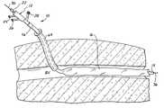
- FIG. 1is a cross section showing the catheter of the invention percutaneously inserted into a blood vessel.
- FIG. 2is a drawing of the distal portion of the catheter with a heat exchange balloon located in the left common carotid artery.
- FIG. 3is a longitudinal cross-sectional view of the proximal end of a catheter of the invention with the inflatable insulation region in a deflated condition.
- FIG. 3Ais a transverse cross-sectional view of a heat exchange fluid manifold of the catheter of the invention taken along line A—A in FIG. 3 .
- FIG. 3Bis a transverse cross-sectional view of the heat exchange fluid manifold taken along line B—B in FIG. 3 .
- FIG. 3Cis a transverse cross-sectional view of an insulation fluid manifold of the catheter of the invention taken along line C—C in FIG. 3 .
- FIG. 3Dis a transverse cross-sectional view of an inflatable insulation region of the catheter of the invention, shown uninflated, and taken along line D—D in FIG. 3 .
- FIG. 4is a longitudinal cross-sectional view of the proximal end of the catheter of the invention with the inflatable insulation region in an inflated condition.
- FIG. 4Ais a transverse cross-sectional view of the inflatable insulation region of the catheter of the invention, shown inflated, and taken along line A—A in FIG. 4 .
- FIG. 4 A′is a transverse cross-sectional view of an alternative embodiment of the inflatable region of the catheter of the invention, shown inflated, and again taken along line A—A in FIG. 4 .
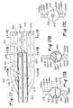
- FIG. 5is an elevational view of a heat exchange region of a catheter of the invention.
- FIG. 5Ais an elevational view of an alternative heat exchange region of the present invention.
- FIG. 6is an elevational view of a shaft portion of the catheter with the twisted heat exchange balloon seen in FIG. 5 removed.
- FIG. 7is an isolated view of the twisted heat exchange balloon of the catheter depicted in FIG. 5 .
- FIG. 8is a detailed view of a proximal section of the heat exchange region of the catheter taken within the circle 8 in FIG. 5 .
- FIG. 9is a detailed view of a distal section of the heat exchange region of the catheter taken within the circle 9 in FIG. 5 .
- FIG. 10is transverse cross-sectional view of the shaft of the catheter taken along line 10 — 10 in FIG. 6 .
- FIG. 11is a transverse cross-sectional view of the twisted heat exchange balloon taken along line 11 — 11 in FIG. 7 .
- FIG. 12is a transverse cross-sectional view of a proximal section of the heat exchange region of the catheter taken along line 12 — 12 in FIG. 5 .
- FIGS. 12A-12 care transverse cross-sectional views of the alternative heat exchange region of the catheter of FIG. 5 A.
- FIG. 13is a transverse cross-sectional view of a mid-section of the heat exchange region of the catheter taken along line 13 — 13 of FIG. 5 .
- FIG. 14is a transverse cross-sectional view of a distal section of the heat exchange region of the catheter taken along line 14 — 14 of FIG. 5 .
- FIG. 15is a schematic elevational view of a heat exchange catheter of the present invention inserted femorally and through the abdominal aorta of a patient so that a heat exchange region is located in one of the carotid arteries.
- FIG. 15Ais a detailed view of a heat exchange region of the catheter of FIG. 15 taken within the circle 15 A.
- FIG. 16is a plan view of a segment of the heat exchange region of the catheter of FIG. 15 .
- FIG. 16Ais a cross-sectional view of the heat exchange region of FIG. 16, taken along line 16 A— 16 A.
- FIG. 17is a longitudinal cross-sectional view of a proximal manifold portion of the heat exchange region of the catheter of FIG. 15 .
- FIG. 17Ais a transverse cross-sectional view of the heat exchange region taken along line 17 A— 17 A of FIG. 17 .
- FIG. 17Bis a transverse cross-sectional view of the heat exchange region taken along line 17 B— 17 B of FIG. 17 .
- FIG. 17Cis a transverse cross-sectional view of the heat exchange region taken along line 17 C— 17 C of FIG. 17 .
- FIG. 18is a longitudinal cross-sectional view of a proximal manifold portion of the heat exchange region of the catheter of FIG. 15 .
- FIG. 18Ais a transverse cross-sectional view of the heat exchange region taken along line 18 A— 18 A of FIG. 18 .
- FIG. 18Bis a transverse cross-sectional view of the heat exchange region taken along line 18 B— 18 B of FIG. 18 .
- FIG. 19is a schematic elevational view of an alternative heat exchange region suitable for use with the heat exchange catheters of the present invention.
- FIG. 20is a schematic elevational view of another alternative heat exchange region suitable for use with the heat exchange catheters of the present invention.
- the present inventionprovides a heat exchange catheter with an improved insulation region on the shaft of the catheter, which insulation region provides improved thermal insulation without significantly increasing the insertion profile of the catheter.
- the present inventionis primarily intended to be used in the bloodstream with a catheter that cools blood flowing to specific locations in the patient's body to regulate the temperature of tissue at that location, those of skill in the art will readily appreciate that various other applications for the insulation region of the present invention are possible. Indeed, the present invention may have applications beyond controlling the temperature of tissue and circulating body fluid, and the claims should not be so limited.
- a catheter of the present inventionis positioned within a patient's vasculature to exchange heat with the blood in order to regulate the overall body temperature, or to regulate the temperature of a localized region of the patient's body.
- the catheter of the present inventionmay be, for example, suitable for exchanging heat with arterial blood flowing toward the brain to cool the brain, and may thus prevent damage to brain tissue that might otherwise result from a stroke or other injury.
- the cathetermay be used to cool venous blood flowing toward the heart to cool the myocardium and prevent tissue injury that might otherwise occur following a myocardial infarct (MI) or other similar event.
- MImyocardial infarct
- an exemplary embodiment of the heat exchange catheter 10 of the inventioncomprises a proximal hub 12 , a shaft 14 , an insulating sheath 16 , a heat exchange region 18 which may be in the form of an inflatable balloon, and a distal tip 29 .
- the hub 12may include a working port 22 , an inflow port 24 , an outflow port 26 , and an inflation port 28 .
- a length of the proximal end of the catheter shaft 14is contained within the hub 12 .
- the hub 12may be sealed around the shaft 14 , such as by injection molding, or the shaft may be inserted into a bore formed through the hub.
- the hubmay be separately formed with a throughbore into which the shaft 14 inserts and is affixed with, for example, adhesives or thermal bonding.
- the shaft 14has three lumens running along its length to the distal tip 29 : a working lumen 30 , an inflow lumen 32 and an outflow lumen 34 .
- the working port 22communicates with the working lumen 30 so that the operator may insert items through the working port, through the working lumen and thus out the distal tip 29 of the catheter.
- a guide wire 36may be inserted into the working lumen 30 and out the distal tip 29 to guide the insertion of the catheter.
- the working lumen 30may be useful for injection of medicaments, insertion of a temperature probe, measurement of pressure, and the like.
- the inflow lumenis lumen 32
- the outflow lumenis 34 .
- the direction of flow of the heat exchange fluid, as described below,may be reversed if desired by reversing the flow in the inflow and outflow lumens.
- the heat exchange catheter 10 of this embodimenthas a heat exchange region 18 , preferably in the form of a balloon, that receives heat exchange fluid from the inflow lumen 32 of the shaft 14 .
- the heat exchange fluidcirculates through the balloon interior and returns proximally along the shaft 14 through the outflow lumen 34 .
- the heat exchange region 18in conjunction with a shaft 14 of the configuration of the embodiment described herein, is illustrated in greater detail in FIGS. 5 through 14.
- An inflow channel 42is formed through the inflow port 24 and hub 12 , and an opening 38 (FIG. 3A) is formed in the wall of the inflow lumen in the portion of the shaft 14 contained within the hub.
- the inflow channel 42is in fluid communication with inflow lumen 32 at the opening 38 .
- an outflow channel 44is formed through the outflow port 26 and hub 12 , and an opening 40 (FIG. 3B) is formed in the wall of the outflow lumen 34 in the portion of the shaft 14 contained within the hub.
- the outflow channel 44is in fluid communication with the outflow lumen 34 at the opening 40 .
- an inflation manifold 46is located around the catheter shaft 14 distally with respect to the hub 12 .
- An inflation channel 48extends through the inflation port 28 , and communicates with an interior space 50 of the inflation manifold 46 .
- a seal 52is formed, for example by adhesive or potting compound, between the inflation manifold 46 and a coupling end 54 provided on the proximal end of the insulating sheath 16 .
- the interior volume of the insulating sheath 16is in fluid communication with the interior space 50 of the inflation manifold 46 so that an inflation medium such as CO 2 or Helium may be introduced through the inflation port 28 via the inflation channel 48 to inflate the insulating sheath. Consequently, the insulating sheath 16 may be expanded from an uninflated state (e.g., as seen at 16 in FIG. 3) by the introduction of an inflation medium, to an inflated state, as seen at 16 in FIG. 4 .
- various meansmay be provided to center the insulated portion of the shaft within the insulation sheath.
- tethers 56may be provided to attach the inner surface of the insulation sheath 16 to the outer surface of the shaft 14 . When the insulation sheath 16 is fully inflated, these tethers 56 serve to generally center the shaft 14 within the insulating sheath. The centering function of the tethers 56 serves to maximize the overall insulating effect of the inflated sheath 16 by keeping the shaft 14 as far away from the walls of the sheath as possible, thus ensuring that the shaft will have the maximum insulated distance at all points along its length.
- the centering elements 56may be collapsible stand-offs attached to the outer surface of the shaft 14 to hold the inflated sheath 16 away from the shaft and thereby center the shaft within the insulating sheath.
- FIG. 4 A′Another method of centering the shaft 14 within the insulating sheath employs a structure with multiple thin-walled tubes surrounded by the sheath 16 , said tubes readily inflatable under pressure and collapsible under vacuum.
- This constructionis depicted in FIG. 4 A′.
- a central thin-walled tube 58 large enough to accommodate the shaft 14is surrounded by a plurality of internal tubes 60 , 61 , 62 , 63 . When all the lumens defined by the internal tubes 60 , 61 , 62 , 63 are inflated, they hold the insulating sheath 16 around the shaft 14 at a uniform distance approximately equal to the diameter of the internal lumens. In this way the shaft 14 is centered within the insulating sheath.
- any number of heat exchange probes or cathetersmay utilize the expandable insulation of this invention.
- One example of a catheter for such useis shown and described in relation to FIGS. 5 through 14 inclusive.
- the assembled catheter 10has an exemplary heat exchange region 18 in the form of a four-lumen, thin-walled balloon 70 which is attached over the distal portion of the catheter shaft 14 .
- the cross-sectional view of the four-lumen balloon 70is shown in FIG. 11 .
- the balloonhas three elongated lobes that define outer lumens 74 , 76 , 78 and are wound in a helical pattern around an inner lobe defining an inner lumen 80 .
- All four lumensare defined by the lobes of a thin walled balloon (and can be viewed as four separate balloons), and each outer lumen 74 , 76 , 78 shares a common thin wall segment 82 with the inner lumen 80 .
- both the proximal end 84 and the distal end 86 of the balloon 70are sealed around the shaft in a fluid tight seal.
- the shaft 14is at the extruded outer diameter of about 0.118 inches.
- the internal configurationis as shown for example, in cross-section 3 D or in the shaft as shown in FIG. 4 A.
- the shaft 14is necked down at 88 .
- the outer diameter of the shaft 14is reduced to about 0.10 to 0.11 inches, but the internal configuration of the lumens is maintained. Compare, for example, the shaft cross-section of FIG. 10 with the cross-section shown in FIG. 12 .
- This length of reduced diameter shaft 14remains at approximately constant diameter of about 0.10 to 0.11 inches between the necked down location at 88 and a further necked down location at 90 (FIG. 6 ).
- a proximal balloon marker band 91is attached around the shaft 14 .
- the marker bandis a radiopaque material such as a platinum or gold band or radiopaque paint, and is useful for locating the proximal end of the balloon 70 by means of fluoroscopy while the catheter is within the body of the patient.
- all four lobes of the balloon 70are reduced down and are fastened to the inner member at 84 (see FIG. 5 ).
- Thismay be accomplished by folding the balloon 70 down around the shaft 14 , placing a sleeve, for example a short length of tubing, over the balloon and inserting adhesive, for example by wicking the adhesive, around the entire inner circumference of the sleeve. This simultaneously fastens the balloon 70 down around the shaft 14 , and creates a fluid tight seal at the proximal end of the balloon.
- a series of axially-spaced windows 92 , 94 , 96is cut through the wall of the outflow lumen 34 in the shaft 14 , as seen in FIG. 6 .
- groups of slits 98 , 100 , 102are cut into the wall of the outer balloon lumens 74 , 76 , 78 , respectively.
- the outer tubes having the outer lumens 74 , 76 , 78are twined about the shaft 14 in a helical fashion, each of the outer lumens passes over a generatrix of the shaft adjacent the outflow lumen 34 of the shaft at a slightly different axial location.
- each outer lumen 74 , 76 , 78passes over the outflow lumen 34 , one of the windows 92 , 94 , 96 is registered with one of the groups of slits 98 , 100 , 102 to fluidly connect the proximal portion of the respective outer lumens 74 , 76 , 78 to the outflow lumen of the shaft 14 .
- an elongate window 92 ′may be cut through the wall of the outflow lumen 34 ′.
- an annular space 91 ′surrounds the shaft 14 ′ within the inner lobe of the balloon 70 ′ that forms the inner lumen 80 ′.
- five groups of slits 98 ′, 100 ′ and 102 ′are cut into the common wall between each of the outer balloon lumens and the inner lumen 80 ′.
- each of the outer tubespasses over the outflow lumen of the inner shaft member at a slightly different location along the length of the inner shaft.
- the elongate window 92 ′is sufficiently long that each of the outer lumens passes 74 ′, 76 ′, 78 ′ over the elongate window at a point where at least one slit from each group of the slits 98 ′, 100 ′ and 102 ′ is cut into the common wall (as depicted in the cross-sections 12 A- 12 C).
- each of the outer lumens 74 ′, 76 ′, 78 ′is in fluid connection with the outflow lumen 34 ′ over a relatively short distances of the balloon, either directly through a slit over the elongate window 92 ′, or via the annular space 91 ′.
- FIG. 5Ashows the slits in all the exterior balloon lobes as being formed along the same linear axis over the window 92 ′, but it will be readily perceived that the windows may be staggered around the balloon so that they are formed along a shorter length of the balloon, for example 2 cm. Desirably, because of the length of the window 92 ′ and the pitch of the twisted lobes, at least one of the slits in each group will be positioned directly over the window.
- the tube defining the inner lumen 80 of the four-lumen balloon 70is sealed around the shaft 14 in a fluid tight seal, as indicated in FIG. 5 at 104 .
- the outflow lumen 34is thereafter plugged as seen at 106 , and the inflow lumen is open to the inner lumen 80 . (See FIG. 13.) As shown in FIG.
- thismay be accomplished by necking down the shaft 14 to seal the outflow lumen shut at 106 , removing the wall of the inflow lumen 32 , piercing a small hole in the wall of the inner lumen at 110 , wicking UV curable adhesive into the hole and around the entire outside of the shaft, and then curing the adhesive to create a plug 111 about the wall of the shaft 14 .
- This adhesive plugserves to prevent the portion of the inner lumen proximal to the plug 111 from being in fluid communication with the inner member distal to the plug.
- the guide wire lumen 30 of the shaftmay be terminated and joined to a guide wire tube 112 at a location just distal of the necked down location 90 .
- the distal end 86 of the balloon 70 including all four lumens of the balloonis sealed down around the guide wire tube 112 in a manner similar to the way the balloon is sealed at the proximal end 84 around the shaft 14 .
- slits 116Just proximal of the seal, slits 116 (FIGS.
- a distal marker band 118is placed around the guide wire tube 112 .
- a flexible length of tube 120may be joined onto the distal end of the guide wire tube 112 to provide a flexible tip to the catheter 10 .
- the distal end 29 of the flexible tube 120is open so that a guide wire may exit the tip, or medicine or radiographic fluid may be injected distal of the catheter through the working lumen.
- the catheter 10is inserted into the patient, for example, percutaneously into a blood vessel BV by the well known Seldinger technique.
- the catheter 10may be directly inserted, or may be inserted through an introducer sheath 64 (FIG. 1 ).
- the catheteris inserted with the insulating sheath 16 in an uninflated condition (FIG. 3 ).
- the insulating sheath 16may be inflated (FIG. 4) with a suitable inflation fluid, for example with a biocompatible gas such as CO 2 or Helium.
- a suitable inflation mediumwill be any fluid that is provides adequate insulation, is non-toxic, and generally will dissolve in blood so that, should a leak occur in the insulating balloon, the escaping gas will dissolve in the blood and be expelled through the lungs and will not form harmful bubbles in the blood stream.
- the gap formed between the insulating sheath 16 and the shaft 14provides excellent thermal insulation, and the tethers 56 (FIG. 4A) or tubes 60 , 61 , 62 , 63 (FIG. 4 A′) center the shaft within the inflated insulated region.
- the inflation fluidwill be maintained within the insulating sheath 16 at relatively low pressures.
- the portion of the insulating sheath 16 that is within the introducer sheath 62 or the incisionwill not fully inflate at the relatively low pressures that are used, though the inflation medium will be permitted to pass through such narrowed regions.
- the inflation pressureshould be sufficient to fully inflate the portion of the insulating sheath that is within the blood vessel against normal blood pressures, and sufficient pressure to flow through the sheath or incision to inflate the sheath, but no greater so that if there is a rupture, only a minimal amount of inflation medium will be introduced into the blood stream.
- the inflation pressureshould be no more than 2 psi above blood pressure in the vessel in which it is located.
- the inflation sourcedesirably has a flow restrictor that limits inflow of inert gas to the interior of the insulation region to a rate similar to the rate the gas would be absorbed by the body, e.g., 2 cc/min to 3 cc/min if the inflation medium is CO 2 .
- the catheteris inserted into the body of a patient so that the balloon 70 is within a blood vessel BV.
- Heat exchange fluidis circulated into the inflow port 24 , travels down the inflow lumen 32 and into the inner lumen 80 of the four-lumen balloon 70 .
- the heat exchange fluidtravels to the distal end of the inner lumen 80 and then through the slits 116 between the inner lumen 80 and the outer lumens 74 , 76 , 78 , as depicted in FIG. 9 .
- each outer lumenis located over the portion of the shaft having a window 92 , 94 , 96 to the outflow lumen 34 and the outer balloon lumens have slits 98 , 100 , 102 that are aligned with the windows.
- the heat transfer fluidpasses through the slits 98 , 100 , 102 through the windows 92 , 94 , 96 and into the outflow lumen 34 .
- FIG. 8shows fluid passing from the lumens 74 , 76 , 78 through slits 102 and window 96 into outflow lumen 34 . From there it is circulated out of the catheter through the outflow port 26 .
- thermal insulation along that length of the catheter shaftis particularly helpful. This may be true if a regional heating or cooling effect is desired, as would be the case with regional cooling of the brain as described below, or if the tissue between the insertion point and the heat exchange region needed to be protected from temperature exchange with the shaft.
- An example of the lafter situationis where very hot fluid is transmitted to the heat exchange region, as might be the case with heated balloon angioplasty, a thermodilution procedure, or thermal ablation at the heat exchange region. In such situations, an inflatable insulation region along the catheter length would be particularly desirable.
- the heat exchange catheter 10 of the present inventionis useable to perform regional percutaneous temperature regulation (rPTRTM) (the acronym rPTR is a trademark of Radiant Medical, Inc. of Redwwod City, Calif.).
- rPTRTMregional percutaneous temperature regulation
- Such rPTRTM procedureis accomplished by percutaneously inserting the catheter 10 into a blood vessel and advancing the catheter 10 through the patient's vasculature until its heat exchange region 18 is positioned within or slightly upstream of the particular region of the body that is to be heated or cooled.
- a heated or cooled heat exchange mediumis infused through the catheter shaft 14 to the heat exchange region 18 .
- insulating sheath 16is deployed or utilized to minimize heat exchange between the catheter shaft 14 proximal to the heat exchange region 18 and the patient's blood flowing thereby. In this manner, effectve heat exchange with the patient's blood occurs only at the heat exchange region 18 of the catheter 10 .
- Such devices where the inflatable insulating sheath of this invention would be particularly advantageouswould be, for example, in heat exchange catheters intended to provide directed cooling to a patient's brain. Such a catheter might be constructed as shown in FIGS. 15-20.
- Other catheters where the inflatable insulating sheath of this invention would be particularly advantageousare disclosed in U.S. Pat. No. 5,957,963 to Dobak, III, and in WO 99/48449, both assigned to Del Mar Medical Technologies, Inc.
- the magnitude of heat exchangeis a function of the difference between the temperature of the blood flowing past the heat exchange region and the temperature of the surface of the heat exchange elements, a difference that may be described as ⁇ T. If cooled (or heated) blood is to be directed to a specific location in the patient, the greatest ⁇ T must be maintained between the heat transfer region and the blood that subsequently flows to that region.
- the heat transfer cathetermay be inserted into the leg or abdominal region and advanced through the vasculature, forexample up the aorta 124 , to the carotid artery 126 .
- This general configurationis shown if FIG. 2 .
- the heat transfer region 18is placed essentially entirely into the carotid artery. Heat transfer fluid is circulated from outside the patient, up the shaft 14 , to the heat transfer region 18 , and then back down the shaft and out of the body. The desired effect is to cool blood directed through the carotid to the brain and thus cool the brain.
- All heat transferred to the heat exchange medium in the shaft 14 from the blood in the aorta 124would affect primarily blood being carried away from the head and would not serve to cool the brain. In fact, where the operator desires to maintain normothermia in the rest of the body while cooling only the brain, this lost heat would serve to undesirably cool the rest of the body. Not only would the heat transferred in the aorta serve to cool the rest of the body and not the brain, but it would simultaneously decrease the cooling effect directed to the brain by increasing the temperature of the heat exchange fluid and thus decreasing the ⁇ T between the heat exchange region and the blood of the patient.
- An effective insulating member along the catheter shaftmay prevent undue thermal exchange between the heat exchange fluid proximal ofthe heat exchange region, and thus ensure the maximum ⁇ T between the heat exchange region and the patient's blood.
- most truly effective thermal insulation available prior to the inventionare sufficiently bulky to unacceptably increase the diameter of the catheter assembly prior to insertion so that percutaneous insertion into a small incision or through a small conduit such as a sheath trocar or body orifice, is not feasible.
- the inflatable insulation of the inventioncould be inserted in its uninflated state into a body cavity such as a blood vessel, the peritoneal cavity, the bladder or the like through an incision or conduit that is significantly smaller in diameter than the cavity, inflated after insertion, and provide effective insulation.
- the insertion channelbe it formed by a percutaneous incision or puncture or by a trocar or introducer, for example, is preferably 9 French or less in size, but may be larger, for example as large as 13 French.
- FIGS. 15-20illustrate various heat exchange regions suitable for use with catheters of the present invention.
- the heat exchange regions showncan be provided on the distal portion of a heat exchange catheter, wherein an insulating region is provided on a proximal portion, or along the entire proximal length of the catheter that is within the body.
- FIGS. 15 and 15Aillustrate a heat exchange catheter 200 inserted through one of the femoral arteries and advanced until a heat exchange region 202 is located within one of the carotid arteries of the neck.
- the catheter 200comprises the heat exchange region 202 on a distal end, an elongate insulating region 204 located proximally thereto, and an inner shaft 206 extending substantially the entire length of the catheter.
- the catheter 200passes into the body through an introducer 208 and includes a proximal hub 210 .
- the heat exchange region 202is connected to the shaft 206 , as best 20 seen in FIG. 15 A. Heat is transferred to and from the heat exchange region 202 via the shaft 206 , and the insulating region 204 helps improve the efficiency of the device by inhibiting heat transfer between the vasculature and the shaft 206 .
- FIGS. 16 and 16Aillustrate one exemplary embodiment of a heat exchange region 202 comprising a plurality of tubular members that are stacked in a helical plane. More specifically, a central tube 220 defines a central lumen 222 therewithin. A pair of smaller intermediate tubes 224 a , 224 b attaches to the exterior of the central tube 220 at diametrically opposed locations. Each of the smaller tubes 224 a , 224 b defines a fluid lumen 226 a , 226 b therewithin.
- a pair of outer tubes 228 a , 228 battaches to the exterior of the intermediate tubes 224 a , 224 b in alignment with the aligned axes of the central tube 220 and intermediate tubes 224 a , 224 b .
- Each of the outer tubes 228 a , 228 bdefines a fluid lumen 230 a , 230 b within.
- An inflow path of heat exchange mediumis provided by the central tube 220 , as described in greater detail below.
- the intermediate tubes 224 a , 224 b and outer tubes 228 a , 228 bdefine a fluid outflow path within the heat exchange region 202 .
- Heat exchange fluidis transferred into the catheter 200 through an inflow port 240 of the hub 210 , as seen FIG. 15, and is removed from the catheter 200 through an outflow port 242 .
- a working lumen port 244is also provided on the hub 210 .
- the shaft 206extends a short distance, desirably about 3 cm, within the central tube 220 and is thermally or adhesively sealed to the interior wall of the central tube as seen at 250 .
- the shaft 206includes a planar bulkhead 252 that generally evenly divides the interior space of the shaft 206 into an inflow lumen 254 and an outflow lumen 256 .
- a working or guidewire lumen 260is defined within a guidewire tube 262 that is located on one side of the shaft 206 in line with the bulkhead 252 .
- the shaft 206is formed by extrusion.
- the outflow lumen 256is sealed by a plug 264 or other similar expedient at the terminal end of the shaft 206 .
- the inflow lumen 254remains open to the central lumen 222 of heat exchange region 202 .
- the guidewire tube 262continues a short distance and is heat bonded at 270 to a guidewire extension tube 272 generally centered within the central tube 220 .
- a fluid circulation pathis illustrated by arrows in FIG. 17 and generally comprises fluid passing distally through the inflow lumen 254 and then through the entirety of the central lumen 222 .
- Fluidreturns through the lumens 226 a , 226 b , and 230 a , 230 b of the intermediate and outer tubes 224 a , 224 b , and 228 a , 228 b , respectively, and enters reservoirs 274 and 275 .
- two windowsmay be formed 276 and a counterpart not shown in FIG.
- a distal manifold of the heat exchange region 202is shown and described with respect to FIGS. 18 and 18 A- 18 B.
- the outer tubes 228 a , 228 btaper down to meet and seal against the central tube 220 which, in turn, tapers down and seals against the guidewire extension tube 272 .
- Fluid flowing distally through the central lumen 222passes radially outward through a plurality of apertures 280 provided in the central tube 220 .
- the apertures 280open to a distal reservoir 282 in fluid communication with lumens 226 a , 226 b , and a distal reservoir 281 in fluid communication with lumens 230 a , 230 b of the intermediate and outer tubes 224 a , 224 b , and 228 a , 228 b.
- heat exchange fluid introduced into the input port 240will circulates through the inflow lumen 254 , into the central lumen 222 , out through the apertures 280 , and into the distal reservoir 282 . From there, the heat exchange fluid will travel proximally through both intermediate lumens 226 a , 226 b and outer lumens 230 a , 230 b to the proximal reservoirs 274 and 275 . Fluid then passes radially inwardly through the apertures 276 and port 278 into the outflow lumen 256 . Then the fluid circulates back down the shaft 206 and out the outlet port 242 .
- the twisted ribbon configuration of FIGS. 15-18is advantageous for several reasons.
- the relatively flat ribbondoes not take up a significant cross-sectional area of a vessel into which it is inserted.
- the twisted configurationfurther prevents blockage of flow through the vessel when the heat exchange region 202 is in place.
- the helical configuration of the tubes 224 a , 224 b , 228 a , 228 balso aids to center the heat exchange region 202 within a vessel by preventing the heat exchange region from lying flat against the wall of the vessel along any significant length of the vessel. This maximizes heat exchange between the lumens and the blood flowing next to the tubes.
- the twisted ribbon configurationis ideal for maximum heat exchange and blood flow in a relatively small vessel such as the carotid artery.
- an exemplary cross-sectionhas a maximum diameter of about 5.9 mm, permitting treatment of relatively small vessels.
- FIGS. 19 and 20Other heat exchange regions suitable for use with catheters of present invention are seen in FIGS. 19 and 20.
- a flexible metal heat exchange region 300comprises a bellows configuration with a convoluted surface having heat exchange fins in the shape of annular folds.
- the annular foldsare desirably hollow and receive circulating heat exchange fluid within.
- the effectiveness of the heat exchange region 300is enhanced with the use of an insulating region 302 surrounding the catheter shaft.
- a flexible metal heat exchange region 310comprises a hollow metal element having spiral heat exchange fins on the external surface.
- a co-axial central tube(not shown) delivers heat exchange fluid into an inner space of the heat exchange region 310 .
- an insulating member 312surrounds the shaft of the exchange catheter for maximum efficiency.
- the heat transfer fluidcould be a liquid or a gas
- the heat transfer regioncould be in the forrn of a balloon, a flexible metallic member, a region with multiple discrete heat exchange members or the like, all without deviating from the spirit of this invention.
- othervariations of the embodiments describedare anticipated within the scope of the invention as claimed.
Landscapes
- Health & Medical Sciences (AREA)
- Vascular Medicine (AREA)
- Thermal Sciences (AREA)
- Engineering & Computer Science (AREA)
- Biomedical Technology (AREA)
- Heart & Thoracic Surgery (AREA)
- Physics & Mathematics (AREA)
- Life Sciences & Earth Sciences (AREA)
- Animal Behavior & Ethology (AREA)
- General Health & Medical Sciences (AREA)
- Public Health (AREA)
- Veterinary Medicine (AREA)
- Media Introduction/Drainage Providing Device (AREA)
Abstract
Description
Claims (31)
Priority Applications (9)
| Application Number | Priority Date | Filing Date | Title |
|---|---|---|---|
| US09/489,142US6428563B1 (en) | 2000-01-21 | 2000-01-21 | Heat exchange catheter with improved insulated region |
| AU2001231029AAU2001231029A1 (en) | 2000-01-21 | 2001-01-19 | Heat exchange catheter with improved insulated region |
| PCT/US2001/001966WO2001052781A1 (en) | 2000-01-21 | 2001-01-19 | Heat exchange catheter with improved insulated region |
| US09/777,612US6610083B2 (en) | 1998-08-24 | 2001-02-06 | Multiple lumen heat exchange catheters |
| US10/442,483US7566341B2 (en) | 1998-08-24 | 2003-05-21 | Multiple lumen heat exchange catheters |
| US12/511,015US8409265B2 (en) | 1998-08-24 | 2009-07-28 | Multiple lumen heat exchange catheters |
| US13/855,521US9237964B2 (en) | 1998-08-24 | 2013-04-02 | Multiple lumen heat exchange catheters |
| US14/997,520US20160199224A1 (en) | 1998-08-24 | 2016-01-16 | Multiple lumen heat exchange catheters |
| US15/683,486US20180055687A1 (en) | 1998-08-24 | 2017-08-22 | Multiple lumen heat exchange catheters |
Applications Claiming Priority (1)
| Application Number | Priority Date | Filing Date | Title |
|---|---|---|---|
| US09/489,142US6428563B1 (en) | 2000-01-21 | 2000-01-21 | Heat exchange catheter with improved insulated region |
Related Parent Applications (1)
| Application Number | Title | Priority Date | Filing Date |
|---|---|---|---|
| US09/138,830Continuation-In-PartUS6620188B1 (en) | 1993-02-10 | 1998-08-24 | Methods and apparatus for regional and whole body temperature modification |
Related Child Applications (3)
| Application Number | Title | Priority Date | Filing Date |
|---|---|---|---|
| US09/138,830Continuation-In-PartUS6620188B1 (en) | 1993-02-10 | 1998-08-24 | Methods and apparatus for regional and whole body temperature modification |
| US09/777,612Continuation-In-PartUS6610083B2 (en) | 1998-08-24 | 2001-02-06 | Multiple lumen heat exchange catheters |
| US10/442,483ContinuationUS7566341B2 (en) | 1998-08-24 | 2003-05-21 | Multiple lumen heat exchange catheters |
Publications (1)
| Publication Number | Publication Date |
|---|---|
| US6428563B1true US6428563B1 (en) | 2002-08-06 |
Family
ID=23942578
Family Applications (1)
| Application Number | Title | Priority Date | Filing Date |
|---|---|---|---|
| US09/489,142Expired - LifetimeUS6428563B1 (en) | 1998-08-24 | 2000-01-21 | Heat exchange catheter with improved insulated region |
Country Status (3)
| Country | Link |
|---|---|
| US (1) | US6428563B1 (en) |
| AU (1) | AU2001231029A1 (en) |
| WO (1) | WO2001052781A1 (en) |
Cited By (77)
| Publication number | Priority date | Publication date | Assignee | Title |
|---|---|---|---|---|
| US20030040782A1 (en)* | 2001-02-22 | 2003-02-27 | Walker Blair D. | Heat exchange catheter having a helically wrapped heat exchanger |
| US6576001B2 (en) | 2000-03-03 | 2003-06-10 | Innercool Therapies, Inc. | Lumen design for catheter |
| US6585752B2 (en) | 1998-06-23 | 2003-07-01 | Innercool Therapies, Inc. | Fever regulation method and apparatus |
| US20030125721A1 (en)* | 1998-03-31 | 2003-07-03 | Yon Steven A. | Method and device for performing cooling or cryo-therapies, for, e.g., angioplasty with reduced restenosis or pulmonary vein cell necrosis to inhibit atrial fibrillation employing tissue protection |
| US6595967B2 (en) | 2001-02-01 | 2003-07-22 | Innercool Therapies, Inc. | Collapsible guidewire lumen |
| US6602276B2 (en) | 1998-03-31 | 2003-08-05 | Innercool Therapies, Inc. | Method and device for performing cooling- or cryo-therapies for, e.g., angioplasty with reduced restenosis or pulmonary vein cell necrosis to inhibit atrial fibrillation |
| US20030226804A1 (en)* | 2002-02-28 | 2003-12-11 | Haley John W. | Wastewater trickle tower biomedia strands arrangement |
| US6676688B2 (en) | 1998-01-23 | 2004-01-13 | Innercool Therapies, Inc. | Method of making selective organ cooling catheter |
| US6685732B2 (en) | 1998-03-31 | 2004-02-03 | Innercool Therapies, Inc. | Method and device for performing cooling- or cryo-therapies for, e.g., angioplasty with reduced restenosis or pulmonary vein cell necrosis to inhibit atrial fibrillation employing microporous balloon |
| US6692488B2 (en) | 1998-01-23 | 2004-02-17 | Innercool Therapies, Inc. | Apparatus for cell necrosis |
| US6719723B2 (en) | 2000-12-06 | 2004-04-13 | Innercool Therapies, Inc. | Multipurpose catheter assembly |
| US20040087935A1 (en)* | 2002-11-01 | 2004-05-06 | Scimed Life Systems, Inc. | Electrophysiological probes having tissue insulation and /or heating device cooling apparatus |
| US6736809B2 (en)* | 2001-09-26 | 2004-05-18 | Cryocath Technologies Inc. | Method and device for treatment of aneurysms |
| US20040104512A1 (en)* | 2002-12-03 | 2004-06-03 | Scimed Life Systems, Inc. | Method for forming catheter curves |
| US20040199114A1 (en)* | 2003-04-01 | 2004-10-07 | Alsius Corporation | Intravascular heat exchange catheter with tissue preservative |
| US20040215177A1 (en)* | 2003-04-24 | 2004-10-28 | Scimed Life Systems, Inc. | Therapeutic apparatus having insulated region at the insertion area |
| US20040236394A1 (en)* | 2003-05-19 | 2004-11-25 | Xia Luo | System and method for insulating skin from intravascular heat exchange catheter |
| US20040249372A1 (en)* | 2001-09-26 | 2004-12-09 | Leonilda Capuano | Method for treatment of aneurysms |
| US20050222649A1 (en)* | 2001-09-26 | 2005-10-06 | Leonilda Capuano | Method for treatment of aneurysms |
| US7018399B2 (en) | 1998-06-23 | 2006-03-28 | Innercool Therapies, Inc. | Method of making selective organ cooling catheter |
| US20060190066A1 (en)* | 2005-02-23 | 2006-08-24 | Worthen William J | System and method for bringing hypothermia rapidly onboard |
| US7181927B2 (en) | 2005-07-01 | 2007-02-27 | Alsius Corporation | Primary heat exchanger for patient temperature control |
| US7291144B2 (en) | 1998-03-31 | 2007-11-06 | Innercool Therapies, Inc. | Method and device for performing cooling- or cryo-therapies for, e.g., angioplasty with reduced restenosis or pulmonary vein cell necrosis to inhibit atrial fibrillation |
| US20070299433A1 (en)* | 2006-06-27 | 2007-12-27 | C2 Therapeutics | Barrett's Esophagus Cryogenic Ablation System |
| US7425216B2 (en) | 2005-03-01 | 2008-09-16 | Alsius Corporation | System and method for treating cardiac arrest and myocardial infarction |
| US20080312644A1 (en)* | 2007-06-14 | 2008-12-18 | Boston Scientific Scimed, Inc. | Cryogenic balloon ablation instruments and systems |
| WO2009048390A1 (en)* | 2007-10-11 | 2009-04-16 | Milux Holding Sa | System and method for thermal treatment of hypertension, hypotension or aneurysm |
| US20090138000A1 (en)* | 2003-12-22 | 2009-05-28 | Vancelette David W | Cryosurgical devices and methods for endometrial ablation |
| US20090182400A1 (en)* | 2002-04-10 | 2009-07-16 | Zoll Circulation, Inc. | Methods and systems for reducing substance-induced renal damage |
| US20090254161A1 (en)* | 1999-12-14 | 2009-10-08 | Zoll Circulation, Inc. | Method for reducing myocardial infarct by application of intravascular hypothermia |
| US20100030307A1 (en)* | 1998-08-24 | 2010-02-04 | Zoll Circulation, Inc. | Multiple lumen heat exchange catheters |
| US7822485B2 (en) | 2006-09-25 | 2010-10-26 | Zoll Circulation, Inc. | Method and apparatus for spinal cooling |
| US7828790B2 (en) | 2004-12-03 | 2010-11-09 | Boston Scientific Scimed, Inc. | Selectively flexible catheter and method of use |
| US7857781B2 (en) | 1998-04-21 | 2010-12-28 | Zoll Circulation, Inc. | Indwelling heat exchange catheter and method of using same |
| US7867266B2 (en) | 2006-11-13 | 2011-01-11 | Zoll Circulation, Inc. | Temperature management system with assist mode for use with heart-lung machine |
| US7892270B2 (en) | 2006-11-21 | 2011-02-22 | Zoll Circulation Inc. | Temperature management system and method for burn patients |
| US7892269B2 (en) | 2005-04-18 | 2011-02-22 | Zoll Circulation, Inc. | External heat exchange pad for patient |
| US7918806B2 (en) | 2001-12-18 | 2011-04-05 | Boston Scientific Scimed, Inc. | Guide wire with adjustable flexibility |
| US7951182B2 (en) | 2005-07-14 | 2011-05-31 | Zoll Circulation, Inc. | System and method for leak detection in external cooling pad |
| US20110313496A1 (en)* | 1993-02-10 | 2011-12-22 | Zoll Circulation, Inc. | Method for Controlling a Patent's Body Temperature |
| US8128595B2 (en) | 1998-04-21 | 2012-03-06 | Zoll Circulation, Inc. | Method for a central venous line catheter having a temperature control system |
| US8353893B2 (en) | 2007-03-07 | 2013-01-15 | Zoll Circulation, Inc. | System and method for rapidly cooling cardiac arrest patient |
| US8439906B2 (en)* | 2008-05-29 | 2013-05-14 | Boston Scientific Schimed, Inc. | Regulating internal pressure of a cryotherapy balloon catheter |
| US20130238064A1 (en)* | 2000-07-25 | 2013-09-12 | Boston Scientific Scimed, Inc. | Cryotreatment device and method |
| US8888832B2 (en) | 2011-09-28 | 2014-11-18 | Zoll Circulation, Inc. | System and method for doubled use of patient temperature control catheter |
| US8956340B2 (en)* | 2012-12-13 | 2015-02-17 | University Of South Florida | Urethral catheter assembly with a guide wire |
| US9241827B2 (en) | 2012-09-28 | 2016-01-26 | Zoll Circulation, Inc. | Intravascular heat exchange catheter with multiple spaced apart discrete coolant loops |
| US9259348B2 (en) | 2011-09-28 | 2016-02-16 | Zoll Circulation, Inc. | Transatrial patient temperature control catheter |
| US9283110B2 (en) | 2011-09-20 | 2016-03-15 | Zoll Circulation, Inc. | Patient temperature control catheter with outer sleeve cooled by inner sleeve |
| US9314370B2 (en) | 2011-09-28 | 2016-04-19 | Zoll Circulation, Inc. | Self-centering patient temperature control catheter |
| US20160158489A1 (en)* | 2013-07-18 | 2016-06-09 | Zhongjun Wu | Self-expanding cannula |
| US9433528B2 (en) | 2012-09-28 | 2016-09-06 | Zoll Circulation, Inc. | Intravascular heat exchange catheter with rib cage-like coolant path |
| WO2016145214A1 (en)* | 2015-03-10 | 2016-09-15 | PAVmed Inc. | Continuous flow balloon catheter systems and methods of use |
| US9474644B2 (en) | 2014-02-07 | 2016-10-25 | Zoll Circulation, Inc. | Heat exchange system for patient temperature control with multiple coolant chambers for multiple heat exchange modalities |
| US20170119413A1 (en)* | 2015-10-30 | 2017-05-04 | Auris Surgical Robotics, Inc. | Object removal through a percutaneous suction tube |
| US9717625B2 (en) | 2012-09-28 | 2017-08-01 | Zoll Circulation, Inc. | Intravascular heat exchange catheter with non-round coiled coolant path |
| US9737692B2 (en) | 2007-05-18 | 2017-08-22 | Zoll Circulation, Inc. | System and method for effecting non-standard fluid line connections |
| US9784263B2 (en) | 2014-11-06 | 2017-10-10 | Zoll Circulation, Inc. | Heat exchange system for patient temperature control with easy loading high performance peristaltic pump |
| US9801756B2 (en) | 2012-09-28 | 2017-10-31 | Zoll Circulation, Inc. | Intravascular heat exchange catheter and system with RFID coupling |
| US10022265B2 (en) | 2015-04-01 | 2018-07-17 | Zoll Circulation, Inc. | Working fluid cassette with hinged plenum or enclosure for interfacing heat exchanger with intravascular temperature management catheter |
| US10045881B2 (en) | 2011-09-28 | 2018-08-14 | Zoll Circulation, Inc. | Patient temperature control catheter with helical heat exchange paths |
| US10500088B2 (en) | 2014-02-14 | 2019-12-10 | Zoll Circulation, Inc. | Patient heat exchange system with two and only two fluid loops |
| US10537465B2 (en) | 2015-03-31 | 2020-01-21 | Zoll Circulation, Inc. | Cold plate design in heat exchanger for intravascular temperature management catheter and/or heat exchange pad |
| US10792185B2 (en) | 2014-02-14 | 2020-10-06 | Zoll Circulation, Inc. | Fluid cassette with polymeric membranes and integral inlet and outlet tubes for patient heat exchange system |
| US11033424B2 (en) | 2014-02-14 | 2021-06-15 | Zoll Circulation, Inc. | Fluid cassette with tensioned polymeric membranes for patient heat exchange system |
| US11116657B2 (en) | 2017-02-02 | 2021-09-14 | Zoll Circulation, Inc. | Devices, systems and methods for endovascular temperature control |
| US11185440B2 (en) | 2017-02-02 | 2021-11-30 | Zoll Circulation, Inc. | Devices, systems and methods for endovascular temperature control |
| US11213423B2 (en) | 2015-03-31 | 2022-01-04 | Zoll Circulation, Inc. | Proximal mounting of temperature sensor in intravascular temperature management catheter |
| US11337851B2 (en) | 2017-02-02 | 2022-05-24 | Zoll Circulation, Inc. | Devices, systems and methods for endovascular temperature control |
| US11359620B2 (en) | 2015-04-01 | 2022-06-14 | Zoll Circulation, Inc. | Heat exchange system for patient temperature control with easy loading high performance peristaltic pump |
| US11382650B2 (en) | 2015-10-30 | 2022-07-12 | Auris Health, Inc. | Object capture with a basket |
| US11439419B2 (en) | 2019-12-31 | 2022-09-13 | Auris Health, Inc. | Advanced basket drive mode |
| US11439532B2 (en) | 2017-04-05 | 2022-09-13 | Miraki Innovation Think Tank Llc | Point of delivery cold slurry generation |
| US11446178B2 (en) | 2017-04-05 | 2022-09-20 | Miraki Innovation Think Tank Llc | Cold slurry containment |
| US11571229B2 (en) | 2015-10-30 | 2023-02-07 | Auris Health, Inc. | Basket apparatus |
| US11806484B2 (en) | 2018-01-19 | 2023-11-07 | Focalcool, Llc | Catheter with heat transfer minimizing annular space |
| US11896330B2 (en) | 2019-08-15 | 2024-02-13 | Auris Health, Inc. | Robotic medical system having multiple medical instruments |
Families Citing this family (11)
| Publication number | Priority date | Publication date | Assignee | Title |
|---|---|---|---|---|
| US6464716B1 (en) | 1998-01-23 | 2002-10-15 | Innercool Therapies, Inc. | Selective organ cooling apparatus and method |
| US6383210B1 (en) | 2000-06-02 | 2002-05-07 | Innercool Therapies, Inc. | Method for determining the effective thermal mass of a body or organ using cooling catheter |
| US6325818B1 (en) | 1999-10-07 | 2001-12-04 | Innercool Therapies, Inc. | Inflatable cooling apparatus for selective organ hypothermia |
| US7371254B2 (en) | 1998-01-23 | 2008-05-13 | Innercool Therapies, Inc. | Medical procedure |
| US6719779B2 (en) | 2000-11-07 | 2004-04-13 | Innercool Therapies, Inc. | Circulation set for temperature-controlled catheter and method of using the same |
| US6905494B2 (en) | 1998-03-31 | 2005-06-14 | Innercool Therapies, Inc. | Method and device for performing cooling- or cryo-therapies for, e.g., angioplasty with reduced restenosis or pulmonary vein cell necrosis to inhibit atrial fibrillation employing tissue protection |
| US6648906B2 (en) | 2000-04-06 | 2003-11-18 | Innercool Therapies, Inc. | Method and apparatus for regulating patient temperature by irrigating the bladder with a fluid |
| US8608696B1 (en) | 2009-02-24 | 2013-12-17 | North Carolina State University | Rapid fluid cooling devices and methods for cooling fluids |
| US8679105B2 (en)* | 2010-07-28 | 2014-03-25 | Medtronic Cryocath Lp | Device and method for pulmonary vein isolation |
| US9492633B2 (en)* | 2011-09-30 | 2016-11-15 | Zoll Circulation, Inc. | Heat exchange catheter and their methods of manufacture and use |
| US9101343B2 (en)* | 2012-08-03 | 2015-08-11 | Thach Buu Duong | Therapeutic cryoablation system |
Citations (9)
| Publication number | Priority date | Publication date | Assignee | Title |
|---|---|---|---|---|
| US5151100A (en) | 1988-10-28 | 1992-09-29 | Boston Scientific Corporation | Heating catheters |
| US5222938A (en) | 1989-09-15 | 1993-06-29 | Interventional Thermodynamics, Inc. | Method for thermal ablation of hollow body organs |
| US5486208A (en)* | 1993-02-10 | 1996-01-23 | Ginsburg; Robert | Method and apparatus for controlling a patient's body temperature by in situ blood temperature modification |
| US5624392A (en) | 1990-05-11 | 1997-04-29 | Saab; Mark A. | Heat transfer catheters and methods of making and using same |
| EP0801938A2 (en) | 1996-04-16 | 1997-10-22 | ARGOMED Ltd. | Thermal treatment apparatus |
| US5928181A (en)* | 1997-11-21 | 1999-07-27 | Advanced International Technologies, Inc. | Cardiac bypass catheter system and method of use |
| US5957963A (en)* | 1998-01-23 | 1999-09-28 | Del Mar Medical Technologies, Inc. | Selective organ hypothermia method and apparatus |
| WO1999066970A1 (en) | 1998-06-23 | 1999-12-29 | Innercool Therapies, Inc. | Selective organ cooling apparatus and method |
| US6042559A (en)* | 1998-02-24 | 2000-03-28 | Innercool Therapies, Inc. | Insulated catheter for selective organ perfusion |
Family Cites Families (3)
| Publication number | Priority date | Publication date | Assignee | Title |
|---|---|---|---|---|
| US4941475A (en) | 1988-08-30 | 1990-07-17 | Spectramed, Inc. | Thermodilution by heat exchange |
| IL93842A (en) | 1990-03-22 | 1995-10-31 | Argomed Ltd | Apparatus for localized thermal treatment of mammals |
| DE69934303T2 (en) | 1998-03-24 | 2007-07-05 | Innercool Therapies, Inc., San Diego | DEVICE FOR COOLING A SELECTED ORGAN |
- 2000
- 2000-01-21USUS09/489,142patent/US6428563B1/ennot_activeExpired - Lifetime
- 2001
- 2001-01-19AUAU2001231029Apatent/AU2001231029A1/ennot_activeAbandoned
- 2001-01-19WOPCT/US2001/001966patent/WO2001052781A1/enactiveApplication Filing
Patent Citations (10)
| Publication number | Priority date | Publication date | Assignee | Title |
|---|---|---|---|---|
| US5151100A (en) | 1988-10-28 | 1992-09-29 | Boston Scientific Corporation | Heating catheters |
| US5222938A (en) | 1989-09-15 | 1993-06-29 | Interventional Thermodynamics, Inc. | Method for thermal ablation of hollow body organs |
| US5624392A (en) | 1990-05-11 | 1997-04-29 | Saab; Mark A. | Heat transfer catheters and methods of making and using same |
| US5486208A (en)* | 1993-02-10 | 1996-01-23 | Ginsburg; Robert | Method and apparatus for controlling a patient's body temperature by in situ blood temperature modification |
| EP0801938A2 (en) | 1996-04-16 | 1997-10-22 | ARGOMED Ltd. | Thermal treatment apparatus |
| US5928181A (en)* | 1997-11-21 | 1999-07-27 | Advanced International Technologies, Inc. | Cardiac bypass catheter system and method of use |
| US5957963A (en)* | 1998-01-23 | 1999-09-28 | Del Mar Medical Technologies, Inc. | Selective organ hypothermia method and apparatus |
| US6051019A (en)* | 1998-01-23 | 2000-04-18 | Del Mar Medical Technologies, Inc. | Selective organ hypothermia method and apparatus |
| US6042559A (en)* | 1998-02-24 | 2000-03-28 | Innercool Therapies, Inc. | Insulated catheter for selective organ perfusion |
| WO1999066970A1 (en) | 1998-06-23 | 1999-12-29 | Innercool Therapies, Inc. | Selective organ cooling apparatus and method |
Cited By (133)
| Publication number | Priority date | Publication date | Assignee | Title |
|---|---|---|---|---|
| US20110313496A1 (en)* | 1993-02-10 | 2011-12-22 | Zoll Circulation, Inc. | Method for Controlling a Patent's Body Temperature |
| US20140257441A1 (en)* | 1993-02-10 | 2014-09-11 | Zoll Circulation, Inc. | Method for Controlling Patient's Body Temperature |
| US6676688B2 (en) | 1998-01-23 | 2004-01-13 | Innercool Therapies, Inc. | Method of making selective organ cooling catheter |
| US7766949B2 (en) | 1998-01-23 | 2010-08-03 | Innercool Therapies, Inc. | Fever regulation method and apparatus |
| US7094253B2 (en) | 1998-01-23 | 2006-08-22 | Innercool Therapies, Inc. | Fever regulation method and apparatus |
| US6692488B2 (en) | 1998-01-23 | 2004-02-17 | Innercool Therapies, Inc. | Apparatus for cell necrosis |
| US7001378B2 (en) | 1998-03-31 | 2006-02-21 | Innercool Therapies, Inc. | Method and device for performing cooling or cryo-therapies, for, e.g., angioplasty with reduced restenosis or pulmonary vein cell necrosis to inhibit atrial fibrillation employing tissue protection |
| US8157794B2 (en) | 1998-03-31 | 2012-04-17 | Innercool Therapies, Inc. | Method and device for performing cooling-or cryo-therapies for, e.g., angioplasty with reduced restenosis or pulmonary vein cell necrosis to inhibit atrial fibrillation |
| US6685732B2 (en) | 1998-03-31 | 2004-02-03 | Innercool Therapies, Inc. | Method and device for performing cooling- or cryo-therapies for, e.g., angioplasty with reduced restenosis or pulmonary vein cell necrosis to inhibit atrial fibrillation employing microporous balloon |
| US6602276B2 (en) | 1998-03-31 | 2003-08-05 | Innercool Therapies, Inc. | Method and device for performing cooling- or cryo-therapies for, e.g., angioplasty with reduced restenosis or pulmonary vein cell necrosis to inhibit atrial fibrillation |
| US7291144B2 (en) | 1998-03-31 | 2007-11-06 | Innercool Therapies, Inc. | Method and device for performing cooling- or cryo-therapies for, e.g., angioplasty with reduced restenosis or pulmonary vein cell necrosis to inhibit atrial fibrillation |
| US8043283B2 (en) | 1998-03-31 | 2011-10-25 | Innercool Therapies, Inc. | Method and device for performing cooling- or cryo-therapies for, e.g., angioplasty with reduced restenosis or pulmonary vein cell necrosis to inhibit atrial fibrillation |
| US7449018B2 (en) | 1998-03-31 | 2008-11-11 | Innercool Therapies, Inc. | Method and device for performing cooling- or cryo-therapies for, e.g., angioplasty with reduced restenosis or pulmonary vein cell necrosis to inhibit atrial fibrillation employing microporous balloon |
| US20030125721A1 (en)* | 1998-03-31 | 2003-07-03 | Yon Steven A. | Method and device for performing cooling or cryo-therapies, for, e.g., angioplasty with reduced restenosis or pulmonary vein cell necrosis to inhibit atrial fibrillation employing tissue protection |
| US7857781B2 (en) | 1998-04-21 | 2010-12-28 | Zoll Circulation, Inc. | Indwelling heat exchange catheter and method of using same |
| US8128595B2 (en) | 1998-04-21 | 2012-03-06 | Zoll Circulation, Inc. | Method for a central venous line catheter having a temperature control system |
| US7018399B2 (en) | 1998-06-23 | 2006-03-28 | Innercool Therapies, Inc. | Method of making selective organ cooling catheter |
| US6585752B2 (en) | 1998-06-23 | 2003-07-01 | Innercool Therapies, Inc. | Fever regulation method and apparatus |
| US8409265B2 (en) | 1998-08-24 | 2013-04-02 | Zoll Circulation, Inc. | Multiple lumen heat exchange catheters |
| US9237964B2 (en) | 1998-08-24 | 2016-01-19 | Zoll Circulation, Inc. | Multiple lumen heat exchange catheters |
| US20100030307A1 (en)* | 1998-08-24 | 2010-02-04 | Zoll Circulation, Inc. | Multiple lumen heat exchange catheters |
| US8568464B2 (en)* | 1999-12-14 | 2013-10-29 | Zoll Circulation, Inc. | Method for reducing myocardial infarct by application of intravascular hypothermia |
| US20090254161A1 (en)* | 1999-12-14 | 2009-10-08 | Zoll Circulation, Inc. | Method for reducing myocardial infarct by application of intravascular hypothermia |
| US6576001B2 (en) | 2000-03-03 | 2003-06-10 | Innercool Therapies, Inc. | Lumen design for catheter |
| US20130238064A1 (en)* | 2000-07-25 | 2013-09-12 | Boston Scientific Scimed, Inc. | Cryotreatment device and method |
| US8845707B2 (en)* | 2000-07-25 | 2014-09-30 | Boston Scientific Scimed, Inc. | Cryotreatment device and method |
| US6979345B2 (en) | 2000-12-06 | 2005-12-27 | Innercool Therapies, Inc. | Multipurpose catheter assembly |
| US6719723B2 (en) | 2000-12-06 | 2004-04-13 | Innercool Therapies, Inc. | Multipurpose catheter assembly |
| US6595967B2 (en) | 2001-02-01 | 2003-07-22 | Innercool Therapies, Inc. | Collapsible guidewire lumen |
| US20030040782A1 (en)* | 2001-02-22 | 2003-02-27 | Walker Blair D. | Heat exchange catheter having a helically wrapped heat exchanger |
| US20050222649A1 (en)* | 2001-09-26 | 2005-10-06 | Leonilda Capuano | Method for treatment of aneurysms |
| US7912554B2 (en) | 2001-09-26 | 2011-03-22 | Medtronic Cryocath Lp | Method for treatment of aneurysms |
| US6736809B2 (en)* | 2001-09-26 | 2004-05-18 | Cryocath Technologies Inc. | Method and device for treatment of aneurysms |
| US20040249372A1 (en)* | 2001-09-26 | 2004-12-09 | Leonilda Capuano | Method for treatment of aneurysms |
| US7918806B2 (en) | 2001-12-18 | 2011-04-05 | Boston Scientific Scimed, Inc. | Guide wire with adjustable flexibility |
| US20030226804A1 (en)* | 2002-02-28 | 2003-12-11 | Haley John W. | Wastewater trickle tower biomedia strands arrangement |
| US20090182400A1 (en)* | 2002-04-10 | 2009-07-16 | Zoll Circulation, Inc. | Methods and systems for reducing substance-induced renal damage |
| US20040087935A1 (en)* | 2002-11-01 | 2004-05-06 | Scimed Life Systems, Inc. | Electrophysiological probes having tissue insulation and /or heating device cooling apparatus |
| US7378048B2 (en) | 2002-12-03 | 2008-05-27 | Boston Scientific Scimed, Inc. | Method for forming catheter curves |
| US20040104512A1 (en)* | 2002-12-03 | 2004-06-03 | Scimed Life Systems, Inc. | Method for forming catheter curves |
| US20040199114A1 (en)* | 2003-04-01 | 2004-10-07 | Alsius Corporation | Intravascular heat exchange catheter with tissue preservative |
| US20040215177A1 (en)* | 2003-04-24 | 2004-10-28 | Scimed Life Systems, Inc. | Therapeutic apparatus having insulated region at the insertion area |
| US20060089631A1 (en)* | 2003-04-24 | 2006-04-27 | Swanson David K | Therapeutic apparatus having insulated region at the insertion area |
| US20080215042A1 (en)* | 2003-04-24 | 2008-09-04 | Swanson David K | Therapeutic Apparatus Having Insulated Region At The Insertion Area |
| US8870859B2 (en)* | 2003-04-24 | 2014-10-28 | Boston Scientific Scimed, Inc. | Therapeutic apparatus having insulated region at the insertion area |
| US20060089630A1 (en)* | 2003-04-24 | 2006-04-27 | Swanson David K | Therapeutic apparatus having insulated region at the insertion area |
| US7306590B2 (en)* | 2003-04-24 | 2007-12-11 | Boston Scientific Scimed, Inc. | Therapeutic apparatus having insulated region at the insertion area |
| US20140018785A1 (en)* | 2003-04-24 | 2014-01-16 | Boston Scientific Scimed, Inc. | Therapeutic apparatus having insulated region at the insertion area |
| US8535305B2 (en)* | 2003-04-24 | 2013-09-17 | Boston Scientific Scimed, Inc. | Therapeutic apparatus having insulated region at the insertion area |
| US7306589B2 (en) | 2003-04-24 | 2007-12-11 | Boston Scientific Scimed, Inc. | Therapeutic apparatus having insulated region at the insertion area |
| US20040236394A1 (en)* | 2003-05-19 | 2004-11-25 | Xia Luo | System and method for insulating skin from intravascular heat exchange catheter |
| US6872222B2 (en)* | 2003-05-19 | 2005-03-29 | Alsius Corporation | System and method for insulating skin from intravascular heat exchange catheter |
| US20090138000A1 (en)* | 2003-12-22 | 2009-05-28 | Vancelette David W | Cryosurgical devices and methods for endometrial ablation |
| US20110054393A1 (en)* | 2004-12-03 | 2011-03-03 | Boston Scientific Scimed, Inc. | Selectively Flexible Catheter and Method of Use |
| US7828790B2 (en) | 2004-12-03 | 2010-11-09 | Boston Scientific Scimed, Inc. | Selectively flexible catheter and method of use |
| US8328791B2 (en) | 2004-12-03 | 2012-12-11 | Stryker Corporation | Selectively flexible catheter and method of use |
| US20060190066A1 (en)* | 2005-02-23 | 2006-08-24 | Worthen William J | System and method for bringing hypothermia rapidly onboard |
| US7425216B2 (en) | 2005-03-01 | 2008-09-16 | Alsius Corporation | System and method for treating cardiac arrest and myocardial infarction |
| US7892269B2 (en) | 2005-04-18 | 2011-02-22 | Zoll Circulation, Inc. | External heat exchange pad for patient |
| US11547601B2 (en) | 2005-04-18 | 2023-01-10 | Zoll Circulation, Inc. | System and method for bringing hypothermia rapidly onboard |
| US7181927B2 (en) | 2005-07-01 | 2007-02-27 | Alsius Corporation | Primary heat exchanger for patient temperature control |
| US8696723B2 (en) | 2005-07-14 | 2014-04-15 | Zoll Circulation, Inc. | System and method for leak detection in external cooling pad |
| US9615966B2 (en) | 2005-07-14 | 2017-04-11 | Zoll Circulation, Inc. | System and method for leak detection in external cooling pad |
| US7951182B2 (en) | 2005-07-14 | 2011-05-31 | Zoll Circulation, Inc. | System and method for leak detection in external cooling pad |
| US20070299433A1 (en)* | 2006-06-27 | 2007-12-27 | C2 Therapeutics | Barrett's Esophagus Cryogenic Ablation System |
| US9180042B2 (en) | 2006-09-25 | 2015-11-10 | Zoll Circulation, Inc. | Method and apparatus for spinal cooling |
| US7822485B2 (en) | 2006-09-25 | 2010-10-26 | Zoll Circulation, Inc. | Method and apparatus for spinal cooling |
| US7867266B2 (en) | 2006-11-13 | 2011-01-11 | Zoll Circulation, Inc. | Temperature management system with assist mode for use with heart-lung machine |
| US7892270B2 (en) | 2006-11-21 | 2011-02-22 | Zoll Circulation Inc. | Temperature management system and method for burn patients |
| US8353893B2 (en) | 2007-03-07 | 2013-01-15 | Zoll Circulation, Inc. | System and method for rapidly cooling cardiac arrest patient |
| US9737692B2 (en) | 2007-05-18 | 2017-08-22 | Zoll Circulation, Inc. | System and method for effecting non-standard fluid line connections |
| US11717665B2 (en) | 2007-05-18 | 2023-08-08 | Zoll Circulation, Inc. | System and method for effecting non-standard fluid line connections |
| US8663211B2 (en) | 2007-06-14 | 2014-03-04 | Boston Scientific Scimed, Inc. | Cryogenic balloon ablation instruments and systems |
| US20080312644A1 (en)* | 2007-06-14 | 2008-12-18 | Boston Scientific Scimed, Inc. | Cryogenic balloon ablation instruments and systems |
| US9968482B2 (en) | 2007-10-11 | 2018-05-15 | Peter Forsell | System and method for thermal treatment of hypertension, hypotension or aneurysm |
| WO2009048390A1 (en)* | 2007-10-11 | 2009-04-16 | Milux Holding Sa | System and method for thermal treatment of hypertension, hypotension or aneurysm |
| US8715274B2 (en) | 2008-05-29 | 2014-05-06 | Boston Scientific Scimed, Inc. | Regulating internal pressure of a cryotherapy balloon catheter |
| US8439906B2 (en)* | 2008-05-29 | 2013-05-14 | Boston Scientific Schimed, Inc. | Regulating internal pressure of a cryotherapy balloon catheter |
| US9283110B2 (en) | 2011-09-20 | 2016-03-15 | Zoll Circulation, Inc. | Patient temperature control catheter with outer sleeve cooled by inner sleeve |
| US9283112B2 (en) | 2011-09-20 | 2016-03-15 | Zoll Circulation, Inc. | Patient temperature control catheter with outer sleeve cooled by inner sleeve |
| US9259348B2 (en) | 2011-09-28 | 2016-02-16 | Zoll Circulation, Inc. | Transatrial patient temperature control catheter |
| US9402764B2 (en) | 2011-09-28 | 2016-08-02 | Zoll Circulation, Inc. | Self-centering patient temperature control catheter |
| US9314370B2 (en) | 2011-09-28 | 2016-04-19 | Zoll Circulation, Inc. | Self-centering patient temperature control catheter |
| US10561526B2 (en) | 2011-09-28 | 2020-02-18 | Zoll Circulation, Inc. | Transatrial patient temperature control catheter |
| US10045881B2 (en) | 2011-09-28 | 2018-08-14 | Zoll Circulation, Inc. | Patient temperature control catheter with helical heat exchange paths |
| US12127971B2 (en) | 2011-09-28 | 2024-10-29 | Zoll Circulation, Inc. | Patient temperature control catheter with helical heat exchange paths |
| US8888832B2 (en) | 2011-09-28 | 2014-11-18 | Zoll Circulation, Inc. | System and method for doubled use of patient temperature control catheter |
| US11571332B2 (en) | 2012-09-28 | 2023-02-07 | Zoll Circulation, Inc. | Intravascular heat exchange catheter and system with RFID coupling |
| US9717625B2 (en) | 2012-09-28 | 2017-08-01 | Zoll Circulation, Inc. | Intravascular heat exchange catheter with non-round coiled coolant path |
| US10596029B2 (en) | 2012-09-28 | 2020-03-24 | Zoll Circulation, Inc. | Intravascular heat exchange catheter with rib cage-like coolant path |
| US9801756B2 (en) | 2012-09-28 | 2017-10-31 | Zoll Circulation, Inc. | Intravascular heat exchange catheter and system with RFID coupling |
| US9241827B2 (en) | 2012-09-28 | 2016-01-26 | Zoll Circulation, Inc. | Intravascular heat exchange catheter with multiple spaced apart discrete coolant loops |
| US9433528B2 (en) | 2012-09-28 | 2016-09-06 | Zoll Circulation, Inc. | Intravascular heat exchange catheter with rib cage-like coolant path |
| US8956340B2 (en)* | 2012-12-13 | 2015-02-17 | University Of South Florida | Urethral catheter assembly with a guide wire |
| US20160158489A1 (en)* | 2013-07-18 | 2016-06-09 | Zhongjun Wu | Self-expanding cannula |
| US10912920B2 (en)* | 2013-07-18 | 2021-02-09 | University Of Maryland, Baltimore | Self-expanding cannula |
| US9474644B2 (en) | 2014-02-07 | 2016-10-25 | Zoll Circulation, Inc. | Heat exchange system for patient temperature control with multiple coolant chambers for multiple heat exchange modalities |
| US10828189B2 (en) | 2014-02-07 | 2020-11-10 | Zoll Circulation Inc. | Heat exchange system for patient temperature control with multiple coolant chambers for multiple heat exchange modalities |
| US10500088B2 (en) | 2014-02-14 | 2019-12-10 | Zoll Circulation, Inc. | Patient heat exchange system with two and only two fluid loops |
| US10792185B2 (en) | 2014-02-14 | 2020-10-06 | Zoll Circulation, Inc. | Fluid cassette with polymeric membranes and integral inlet and outlet tubes for patient heat exchange system |
| US11033424B2 (en) | 2014-02-14 | 2021-06-15 | Zoll Circulation, Inc. | Fluid cassette with tensioned polymeric membranes for patient heat exchange system |
| US12427055B2 (en) | 2014-02-14 | 2025-09-30 | Zoll Circulation, Inc. | Patient heat exchange system with two and only two fluid loops |
| US11353016B2 (en) | 2014-11-06 | 2022-06-07 | Zoll Circulation, Inc. | Heat exchange system for patient temperature control with easy loading high performance peristaltic pump |
| US9784263B2 (en) | 2014-11-06 | 2017-10-10 | Zoll Circulation, Inc. | Heat exchange system for patient temperature control with easy loading high performance peristaltic pump |
| US10502200B2 (en) | 2014-11-06 | 2019-12-10 | Zoll Circulation, Inc. | Heat exchanges system for patient temperature control with easy loading high performance peristaltic pump |
| US10687883B2 (en) | 2015-03-10 | 2020-06-23 | PAVmed Inc. | Continuous flow balloon catheter systems and methods of use |
| WO2016145214A1 (en)* | 2015-03-10 | 2016-09-15 | PAVmed Inc. | Continuous flow balloon catheter systems and methods of use |
| US10213245B2 (en) | 2015-03-10 | 2019-02-26 | PAVmed Inc. | Continuous flow balloon catheter systems and methods of use |
| US10537465B2 (en) | 2015-03-31 | 2020-01-21 | Zoll Circulation, Inc. | Cold plate design in heat exchanger for intravascular temperature management catheter and/or heat exchange pad |
| US11213423B2 (en) | 2015-03-31 | 2022-01-04 | Zoll Circulation, Inc. | Proximal mounting of temperature sensor in intravascular temperature management catheter |
| US11992434B2 (en) | 2015-03-31 | 2024-05-28 | Zoll Circulation, Inc. | Cold plate design in heat exchanger for intravascular temperature management catheter and/or heat exchange pad |
| US12305631B2 (en) | 2015-04-01 | 2025-05-20 | Zoll Circulation, Inc. | Heat exchange system for patient temperature control with easy loading high performance peristaltic pump |
| US11359620B2 (en) | 2015-04-01 | 2022-06-14 | Zoll Circulation, Inc. | Heat exchange system for patient temperature control with easy loading high performance peristaltic pump |
| US11759354B2 (en) | 2015-04-01 | 2023-09-19 | Zoll Circulation, Inc. | Working fluid cassette with hinged plenum or enclosure for interfacing heat exchanger with intravascular temperature management catheter |
| US10022265B2 (en) | 2015-04-01 | 2018-07-17 | Zoll Circulation, Inc. | Working fluid cassette with hinged plenum or enclosure for interfacing heat exchanger with intravascular temperature management catheter |
| US10231793B2 (en)* | 2015-10-30 | 2019-03-19 | Auris Health, Inc. | Object removal through a percutaneous suction tube |
| US20170119413A1 (en)* | 2015-10-30 | 2017-05-04 | Auris Surgical Robotics, Inc. | Object removal through a percutaneous suction tube |
| US12433696B2 (en) | 2015-10-30 | 2025-10-07 | Auris Health, Inc. | Tool positioning for medical instruments with working channels |
| US11559360B2 (en) | 2015-10-30 | 2023-01-24 | Auris Health, Inc. | Object removal through a percutaneous suction tube |
| US11534249B2 (en) | 2015-10-30 | 2022-12-27 | Auris Health, Inc. | Process for percutaneous operations |
| US11571229B2 (en) | 2015-10-30 | 2023-02-07 | Auris Health, Inc. | Basket apparatus |
| US11382650B2 (en) | 2015-10-30 | 2022-07-12 | Auris Health, Inc. | Object capture with a basket |
| US11883323B2 (en) | 2017-02-02 | 2024-01-30 | Zoll Circulation, Inc. | Devices, systems and methods for endovascular temperature control |
| US11951035B2 (en) | 2017-02-02 | 2024-04-09 | Zoll Circulation, Inc. | Devices, systems and methods for endovascular temperature control |
| US11337851B2 (en) | 2017-02-02 | 2022-05-24 | Zoll Circulation, Inc. | Devices, systems and methods for endovascular temperature control |
| US11185440B2 (en) | 2017-02-02 | 2021-11-30 | Zoll Circulation, Inc. | Devices, systems and methods for endovascular temperature control |
| US11116657B2 (en) | 2017-02-02 | 2021-09-14 | Zoll Circulation, Inc. | Devices, systems and methods for endovascular temperature control |
| US11439532B2 (en) | 2017-04-05 | 2022-09-13 | Miraki Innovation Think Tank Llc | Point of delivery cold slurry generation |
| US11446178B2 (en) | 2017-04-05 | 2022-09-20 | Miraki Innovation Think Tank Llc | Cold slurry containment |
| US11806484B2 (en) | 2018-01-19 | 2023-11-07 | Focalcool, Llc | Catheter with heat transfer minimizing annular space |
| US11896330B2 (en) | 2019-08-15 | 2024-02-13 | Auris Health, Inc. | Robotic medical system having multiple medical instruments |
| US11439419B2 (en) | 2019-12-31 | 2022-09-13 | Auris Health, Inc. | Advanced basket drive mode |
| US12318102B2 (en) | 2019-12-31 | 2025-06-03 | Auris Health, Inc. | Advanced basket drive mode |
Also Published As
| Publication number | Publication date |
|---|---|
| AU2001231029A1 (en) | 2001-07-31 |
| WO2001052781A1 (en) | 2001-07-26 |
Similar Documents
| Publication | Publication Date | Title |
|---|---|---|
| US6428563B1 (en) | Heat exchange catheter with improved insulated region | |
| US8409265B2 (en) | Multiple lumen heat exchange catheters | |
| US6409747B1 (en) | Indwelling heat exchange catheter and method of using same | |
| US6893419B2 (en) | Indwelling heat exchange catheter and method of using same | |
| US6702840B2 (en) | Heat exchange catheter with discrete heat exchange elements | |
| US6676690B2 (en) | Inflatable heat transfer apparatus | |
| AU2001233337B2 (en) | Multiple lumen heat exchange catheters | |
| US20040167593A1 (en) | Heat exchange catheter with discrete heat exchange elements | |
| AU2001233337A1 (en) | Multiple lumen heat exchange catheters | |
| AU2006200081B2 (en) | Multiple lumen heat exchange catheters |
Legal Events
| Date | Code | Title | Description |
|---|---|---|---|
| AS | Assignment | Owner name:RADIANT MEDICAL, INC., CALIFORNIA Free format text:ASSIGNMENT OF ASSIGNORS INTEREST;ASSIGNOR:KELLER, WADE A.;REEL/FRAME:010549/0811 Effective date:20000120 | |
| AS | Assignment | Owner name:GATX VENTURES, INC., CALIFORNIA Free format text:SECURITY INTEREST;ASSIGNOR:RADIANT MEDICAL, INC.;REEL/FRAME:012232/0327 Effective date:20010928 | |
| STCF | Information on status: patent grant | Free format text:PATENTED CASE | |
| FPAY | Fee payment | Year of fee payment:4 | |
| AS | Assignment | Owner name:RADIANT MEDICAL, INC., CALIFORNIA Free format text:TERMINATION OF SECURITY INTEREST IN PATENTS (REEL/FRAME NO. 012232/0327);ASSIGNOR:GATX VENTURES, INC.;REEL/FRAME:019204/0292 Effective date:20041021 | |
| AS | Assignment | Owner name:BAY CITY CAPITAL FUND IV L.P., CALIFORNIA Free format text:SECURITY AGREEMENT;ASSIGNOR:RADIANT MEDICAL, INC.;REEL/FRAME:019254/0640 Effective date:20070430 | |
| AS | Assignment | Owner name:HORIZON TECHNOLOGY FUNDING COMPANY LLC,CONNECTICUT Free format text:SECURITY AGREEMENT;ASSIGNOR:RADIANT MEDICAL, INC.;REEL/FRAME:019353/0087 Effective date:20070430 Owner name:HORIZON TECHNOLOGY FUNDING COMPANY LLC, CONNECTICU Free format text:SECURITY AGREEMENT;ASSIGNOR:RADIANT MEDICAL, INC.;REEL/FRAME:019353/0087 Effective date:20070430 | |
| AS | Assignment | Owner name:BAY CITY CAPITAL FUND IV, L.P., CALIFORNIA Free format text:ASSIGNMENT OF ASSIGNORS INTEREST;ASSIGNOR:HORIZON TECHNOLOGY FUNDING COMPANY LLC;REEL/FRAME:019781/0792 Effective date:20070906 Owner name:BAY CITY CAPITAL FUND IV, L.P.,CALIFORNIA Free format text:ASSIGNMENT OF ASSIGNORS INTEREST;ASSIGNOR:HORIZON TECHNOLOGY FUNDING COMPANY LLC;REEL/FRAME:019781/0792 Effective date:20070906 | |
| AS | Assignment | Owner name:BAY CITY CAPITAL FUND IV L.P., CALIFORNIA Free format text:SECURITY AGREEMENT;ASSIGNOR:RADIANT MEDICAL, INC.;REEL/FRAME:019805/0575 Effective date:20070907 | |
| FEPP | Fee payment procedure | Free format text:PAT HOLDER NO LONGER CLAIMS SMALL ENTITY STATUS, ENTITY STATUS SET TO UNDISCOUNTED (ORIGINAL EVENT CODE: STOL); ENTITY STATUS OF PATENT OWNER: LARGE ENTITY | |
| AS | Assignment | Owner name:ZOLL CIRCULATION, INC., CALIFORNIA Free format text:ASSIGNMENT OF ASSIGNORS INTEREST;ASSIGNORS:RADIANT MEDICAL, INC.;BAY CITY CAPITAL FUND IV, L.P.;REEL/FRAME:020679/0246 Effective date:20070918 | |
| FPAY | Fee payment | Year of fee payment:8 | |
| FPAY | Fee payment | Year of fee payment:12 |