US6428503B1 - Surgical instrument for providing suction and irrigation - Google Patents
Surgical instrument for providing suction and irrigationDownload PDFInfo
- Publication number
- US6428503B1 US6428503B1US09/484,939US48493900AUS6428503B1US 6428503 B1US6428503 B1US 6428503B1US 48493900 AUS48493900 AUS 48493900AUS 6428503 B1US6428503 B1US 6428503B1
- Authority
- US
- United States
- Prior art keywords
- surgical tool
- mounting
- elongated housing
- surgical
- tip
- Prior art date
- Legal status (The legal status is an assumption and is not a legal conclusion. Google has not performed a legal analysis and makes no representation as to the accuracy of the status listed.)
- Expired - Lifetime
Links
- 230000002262irrigationEffects0.000titleclaimsabstractdescription12
- 238000003973irrigationMethods0.000titleclaimsabstractdescription12
- 239000004020conductorSubstances0.000claimsabstractdescription8
- 238000003466weldingMethods0.000claimsabstractdescription7
- 238000000034methodMethods0.000claimsdescription13
- 239000011810insulating materialSubstances0.000claimsdescription7
- 238000003754machiningMethods0.000claimsdescription3
- 238000001746injection mouldingMethods0.000claimsdescription2
- 238000004519manufacturing processMethods0.000claimsdescription2
- 239000002184metalSubstances0.000claimsdescription2
- 239000012530fluidSubstances0.000description6
- 238000004140cleaningMethods0.000description4
- 238000001356surgical procedureMethods0.000description4
- 238000001574biopsyMethods0.000description3
- 238000005520cutting processMethods0.000description3
- 238000009413insulationMethods0.000description3
- 229910001220stainless steelInorganic materials0.000description3
- 239000010935stainless steelSubstances0.000description3
- 239000004809TeflonSubstances0.000description2
- 229920006362Teflon®Polymers0.000description2
- 230000008901benefitEffects0.000description2
- 230000001112coagulating effectEffects0.000description2
- 238000010276constructionMethods0.000description2
- 239000003814drugSubstances0.000description2
- 229920001296polysiloxanePolymers0.000description2
- 238000005219brazingMethods0.000description1
- 230000015271coagulationEffects0.000description1
- 238000005345coagulationMethods0.000description1
- 230000008878couplingEffects0.000description1
- 238000010168coupling processMethods0.000description1
- 238000005859coupling reactionMethods0.000description1
- 238000002224dissectionMethods0.000description1
- 238000011010flushing procedureMethods0.000description1
- 210000000232gallbladderAnatomy0.000description1
- 230000009191jumpingEffects0.000description1
- 238000003698laser cuttingMethods0.000description1
- 210000004185liverAnatomy0.000description1
- 238000007726management methodMethods0.000description1
- 239000000463materialSubstances0.000description1
- 238000003801millingMethods0.000description1
- 238000012986modificationMethods0.000description1
- 230000004048modificationEffects0.000description1
- 238000005476solderingMethods0.000description1
- 238000006467substitution reactionMethods0.000description1
- BFKJFAAPBSQJPD-UHFFFAOYSA-NtetrafluoroetheneChemical compoundFC(F)=C(F)FBFKJFAAPBSQJPD-UHFFFAOYSA-N0.000description1
- XLYOFNOQVPJJNP-UHFFFAOYSA-NwaterSubstancesOXLYOFNOQVPJJNP-UHFFFAOYSA-N0.000description1
Images


Classifications
- A—HUMAN NECESSITIES
- A61—MEDICAL OR VETERINARY SCIENCE; HYGIENE
- A61B—DIAGNOSIS; SURGERY; IDENTIFICATION
- A61B18/00—Surgical instruments, devices or methods for transferring non-mechanical forms of energy to or from the body
- A61B18/04—Surgical instruments, devices or methods for transferring non-mechanical forms of energy to or from the body by heating
- A61B18/12—Surgical instruments, devices or methods for transferring non-mechanical forms of energy to or from the body by heating by passing a current through the tissue to be heated, e.g. high-frequency current
- A61B18/14—Probes or electrodes therefor
- A61B18/1482—Probes or electrodes therefor having a long rigid shaft for accessing the inner body transcutaneously in minimal invasive surgery, e.g. laparoscopy
- A—HUMAN NECESSITIES
- A61—MEDICAL OR VETERINARY SCIENCE; HYGIENE
- A61B—DIAGNOSIS; SURGERY; IDENTIFICATION
- A61B18/00—Surgical instruments, devices or methods for transferring non-mechanical forms of energy to or from the body
- A61B18/04—Surgical instruments, devices or methods for transferring non-mechanical forms of energy to or from the body by heating
- A61B18/12—Surgical instruments, devices or methods for transferring non-mechanical forms of energy to or from the body by heating by passing a current through the tissue to be heated, e.g. high-frequency current
- A61B18/14—Probes or electrodes therefor
- A61B2018/1405—Electrodes having a specific shape
- A61B2018/1417—Ball
- A—HUMAN NECESSITIES
- A61—MEDICAL OR VETERINARY SCIENCE; HYGIENE
- A61B—DIAGNOSIS; SURGERY; IDENTIFICATION
- A61B18/00—Surgical instruments, devices or methods for transferring non-mechanical forms of energy to or from the body
- A61B18/04—Surgical instruments, devices or methods for transferring non-mechanical forms of energy to or from the body by heating
- A61B18/12—Surgical instruments, devices or methods for transferring non-mechanical forms of energy to or from the body by heating by passing a current through the tissue to be heated, e.g. high-frequency current
- A61B18/14—Probes or electrodes therefor
- A61B2018/1405—Electrodes having a specific shape
- A61B2018/1422—Hook
- A—HUMAN NECESSITIES
- A61—MEDICAL OR VETERINARY SCIENCE; HYGIENE
- A61B—DIAGNOSIS; SURGERY; IDENTIFICATION
- A61B90/00—Instruments, implements or accessories specially adapted for surgery or diagnosis and not covered by any of the groups A61B1/00 - A61B50/00, e.g. for luxation treatment or for protecting wound edges
- A61B90/08—Accessories or related features not otherwise provided for
- A61B2090/0817—Spatulas or spatula like extensions
- A—HUMAN NECESSITIES
- A61—MEDICAL OR VETERINARY SCIENCE; HYGIENE
- A61B—DIAGNOSIS; SURGERY; IDENTIFICATION
- A61B2218/00—Details of surgical instruments, devices or methods for transferring non-mechanical forms of energy to or from the body
- A61B2218/001—Details of surgical instruments, devices or methods for transferring non-mechanical forms of energy to or from the body having means for irrigation and/or aspiration of substances to and/or from the surgical site
- A61B2218/002—Irrigation
- A—HUMAN NECESSITIES
- A61—MEDICAL OR VETERINARY SCIENCE; HYGIENE
- A61B—DIAGNOSIS; SURGERY; IDENTIFICATION
- A61B2218/00—Details of surgical instruments, devices or methods for transferring non-mechanical forms of energy to or from the body
- A61B2218/001—Details of surgical instruments, devices or methods for transferring non-mechanical forms of energy to or from the body having means for irrigation and/or aspiration of substances to and/or from the surgical site
- A61B2218/007—Aspiration
- A—HUMAN NECESSITIES
- A61—MEDICAL OR VETERINARY SCIENCE; HYGIENE
- A61M—DEVICES FOR INTRODUCING MEDIA INTO, OR ONTO, THE BODY; DEVICES FOR TRANSDUCING BODY MEDIA OR FOR TAKING MEDIA FROM THE BODY; DEVICES FOR PRODUCING OR ENDING SLEEP OR STUPOR
- A61M1/00—Suction or pumping devices for medical purposes; Devices for carrying-off, for treatment of, or for carrying-over, body-liquids; Drainage systems
- A61M1/84—Drainage tubes; Aspiration tips
- A61M1/85—Drainage tubes; Aspiration tips with gas or fluid supply means, e.g. for supplying rinsing fluids or anticoagulants
Definitions
- the present inventionrelates to surgical instruments and in particular, to an electrosurgical laparoscopic instrument that provides suction and irrigation.
- Surgical instrumentsare available that provide irrigation fluid and suction force to irrigate and evacuate the tissue at a surgical site or area where a surgical procedure is being performed.
- an electrosurgical laparoscopic instrument 10FIG. 1, which comprises a housing enclosure (or cannula) 12 having a distal end 16 and an electrode 18 extending from the distal end 16 .
- the housing 12forms a lumen or passageway 19 and is typically constructed of stainless steel with a Teflon shrink wrap insulation.
- the electrode 18includes an insulated electrode connector 20 that extends into the stainless steel tube housing 12 and is attached to a portion of the inner surface 22 of the housing 12 . In use, the laparoscopic instrument 10 is passed through a trocar.
- the tip of the electrode 18is used to dissect a gallbladder from the liver. Energy is applied through the surgical instrument 10 to the electrode 18 to assist in coagulation and cauterization during this dissection procedure.
- the passageway 19allows for suction/irrigation of fluids through the housing 12 , which is controlled, for example, by a trumpet valve.
- This type of electrosurgical laparoscopic instrumentis described in greater detail in U.S. Pat. No. 5,261,905, incorporated herein by reference.
- the passageway 19is obstructed by the electrode 18 or other surgical tool disposed at the distal end 16 of the instrument 10 .
- the electrode 18includes a mounting portion 24 mounted within the passageway 19 , for example, by welding to the inner surface 22 .
- the mounting of the electrode 18thus obstructs the passageway 19 and results in separate flow regions 19 a , 19 b , FIGS. 2 and 3, on either side of the mounting portion 24 of the electrode 18 .
- the surgical instrumentis unable to provide full flow of irrigating fluid during irrigation and does not provide a full passageway for suction of fluid and tissues.
- a further drawback of the obstructed passagewayis the inability to pass other surgical devices, such as, for example, a biopsy needle, through the passageway 19 at the distal end 16 of the surgical instrument 10 with the housing 12 acting as a guide.
- This capabilitywould allow other surgical procedures, such as a biopsy procedure, to be performed at the surgical site more easily and less invasively without having to remove the instrument 10 .
- the trocartypically includes a silicone seal that should fit snugly around the cannula to prevent site leakage. If the electrode 18 is welded to the outer surface of the cannula or housing 12 , the electrode 18 might damage the seal or prevent the seal from fitting snug around the smaller OD of the cannula.
- a channel or dimplecan be formed in the housing 12 to receive the electrode 18 and make the OD consistent, but this will affect the inside diameter (ID) and cause a partial obstruction within the passageway.
- a further disadvantage of this electrosurgical laparoscopic instrument 10 and other such surgical instrumentsis the attachment between the electrode 18 and the inner surface 22 of the housing 12 .
- One way of attaching the electrode 18 , FIG. 4, to the inner surface 22 of the housing 12is by laser welding the edges 26 a , 26 b of the mounting portion 24 by applying the laser generally in the direction of arrows 28 .
- the laser weldingonly welds the portions of the edges 26 a , 26 b that touch the inner surface 22 of the housing 12 .
- edges 26 a , 26 bmay have any irregularities such as a non-linear edge 30 a or a burr 30 b caused, for example, by stamping the electrode 18 , the edges 26 a , 26 b may have insufficient contact with the inner surface and may not be adequately welded. Thus, welding the electrode 18 to the inner surface 22 of the housing 12 can result in a weak attachment, possibly causing the electrode 18 to fall out, for example, during cleaning. The same problem with the strength/durability of the attachment occurs when the electrode is welded or otherwise secured to the outside surface of the housing 12 .
- a further problemoccurs as a result of the passage of electrical current through an electrode 18 that is welded to the inside or outside surface of the housing 12 .
- the gaps that form between the electrode 18 and the housing 12may cause arcing or capacitive coupling to other insulated uninsulated areas.
- Electrosurgical instrumentshave the electrode formed integrally with the housing. In these instruments, however, certain tip shapes and geometries are not possible, such as a ball-shaped tip that has a diameter larger than the wall of the cannula.
- a surgical instrumentthat provides full flow irrigation and suction, that can be properly cleaned without damaging the instrument and safely reused, and that allows passage of another instrument or pharmaceuticals through the passageway.
- an electrosurgical instrumenthaving an electrode that is mounted as part of the wall of the housing to provide a substantially unobstructed passageway, to provide a stronger attachment between the electrode and the housing, to improve electrical contact, and to provide a number of different tip shapes.
- the present inventionfeatures a surgical instrument comprising an elongated housing having a proximal end, a distal end, and a wall defining an inner lumen or passageway extending from the proximal end to the distal end.
- the surgical instrumentfurther comprises a surgical tool extending from the wall of the elongated housing at the distal end such that the lumen or passageway is substantially unobstructed at the distal end.
- the tip of the surgical toolcan have numerous different shapes including, but not limited to, a J hook, and an L hook, a spatula, a needle, and a ball. In one example, the surgical tool is bent such that the tip is positioned generally in the flow path extending from the passageway.
- the wall of the housingincludes a mounting notch at the distal end and the surgical tool includes a mounting tab that mounts within the mounting notch, for example, by laser welding outer edges of the mounting tab to inner edges of the mounting notch.
- the inner edges of the mounting notch and the outer edges of the mounting tabare preferably angled to substantially match.
- the mounting notchis generally rectangular shaped. In another embodiment, the mounting notch is generally key-shaped.
- the surgical instrumentis an electrosurgical instrument, such as an electrosurgical laparoscopic instrument, and the surgical tool acts as an electrode.
- the elongated housingis made of an electrically conductive material and an insulating material is disposed around the elongated housing.
- the surgical toolis also made of an electrically conductive material and includes an insulating material disposed around a base portion of the tool leaving the tip of the electrode exposed.
- the present inventionalso features a method of making a surgical instrument.
- the methodgenerally comprises the steps of: forming an elongated housing having proximal end, a distal end, a wall defining an inner lumen extending from the proximal end to the distal end; forming a mounting notch in the wall at the distal end of the elongated housing; forming a surgical tool having a mounting tab and a tip extending from the mounting tab; inserting the mounting tab of the surgical tool in the mounting notch in the elongated housing; and securing the mounting tab to the wall of the elongated housing and within the mounting notch.
- FIG. 1is a perspective of an electrosurgical laparoscopic instrument according to the prior art
- FIG. 2is a side view of the electrosurgical laparoscopic instrument according to the prior art
- FIG. 3is a cross-sectional view of the instrument, according to the prior art, taken along line 3 — 3 in FIG. 1;
- FIG. 4is a cross-sectional view of the instrument, according to the prior art, taken along line 4 — 4 in FIG. 2;
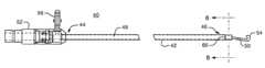
- FIG. 5is a side view of a surgical instrument, according to the present invention.
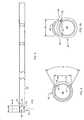
- FIG. 6is a cross-sectional view of the surgical instrument, according to the present invention, taken along line 6 — 6 in FIG. 5;
- FIG. 7is a cross-sectional view of the surgical instrument, according to the present invention, taken along line 7 — 7 in FIG. 6 ;
- FIG. 8is a side view of a housing used in the surgical instrument, according to the present invention.
- FIG. 9is a cross-sectional view of the distal end of the housing, according to the present invention, taken along line 9 — 9 in FIG. 8;
- FIG. 10is an end view of the distal end of the housing and the mounting tab of the surgical tool aligned with the mounting notch in the housing, according to the present invention.
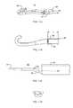
- FIGS. 11 A— 11 Dare views of a surgical tool having a tip with a J-hook shape, according to one embodiment of the present invention.
- FIG. 12is a perspective view of a surgical tool having a tip with a spatula shape, according to another embodiment of the present invention.
- FIG. 13is a perspective view of a surgical tool having a tip with an L-shape, according to a further embodiment of the present invention.
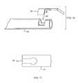
- FIG. 14is a perspective view of the surgical tool having a tip with a ball-shape, according to a further embodiment of the present invention.
- FIG. 15is a perspective view of a surgical tool having a tip with a needle shape, according to a further embodiment of the present invention.
- FIG. 16is a side view of the distal end of a housing having a key-shaped mounting notch and matching key-shaped mounting tab, according to an alternative embodiment of the present invention.
- FIG. 17is a side view of a key-shaped mounting notch, according to a further alternative embodiment.
- the surgical instrument 40includes an elongated housing 42 having a proximal end 44 , a distal end 46 , and a lumen or passageway 48 extending through the housing 42 from the proximal end 44 to the distal end 46 .
- the surgical instrument 40also includes a surgical tool 50 extending from the elongated housing 42 at the distal end 46 and a base 52 attached to the housing 42 at the proximal end 44 .
- the surgical tool 50is attached to the housing 42 such that the passageway 48 at the distal end 46 of the housing 42 is substantially unobstructed, as will be described in greater detail below.
- the surgical tool 50includes a tip 54 that performs surgical procedures at the surgical site within the patient, for example, by cutting and/or cauterizing tissue.
- the base 52is adapted to be coupled to a control valve which controls the flow of fluid and/or tissue through the passageway 48 during irrigation or suction.
- the surgical instrument 40is an electrosurgical instrument used for coagulating fluids and cauterizing tissues at the surgical site.
- the housing 42also known as a cannula
- the surgical tool 50also known as an electrode tip
- the base 52includes a conductor 56 for connecting to an external energy source to provide electric current through the housing 42 to the tip 54 of the surgical tool 50 , which acts as an electrode to coagulate and cauterize.
- a layer of insulating materialsuch as a TEFLON shrink wrap insulation, is disposed around the housing 42 and around a portion of the surgical tool 50 such that only a portion of the tip 54 becomes hot.
- the exemplary embodimentis an electrosurgical instrument, the concepts of the present invention can be applied to any type of surgical instrument.
- the surgical tool 50includes a mounting tab 60 mounted within a mounting notch 62 formed within the side wall 64 of the housing 42 at the distal end 46 .
- the mounting tab 60is laser welded to the side wall 64 of the housing 42 .
- the present inventionalso contemplates attaching or mounting the mounting tab 60 by soldering, brazing or any other method of attachment.
- the inner diameter (ID) within the housing 42is substantially uniform and substantially without any obstructions.
- the unobstructed passageway 48allows full flow of irrigation and full portability for suction of debris.
- Debrisis also less likely to become lodged or clot the end of the passageway 48 , allowing a simple cannula brush to pass through the passageway 48 for cleaning without damaging the instrument.
- the unobstructed passageway 48also allows passage of other instruments (e.g., a biopsy needle) or wound management items (e.g., anti-clot gauze) and/or the delivery of pharmaceuticals.
- Attaching the mounting tab 60 within the mounting notch 62 of the housing 42also provides a substantially uniform outer diameter (OD) such that the requisite amount of energy will travel through the surgical tool 50 for coagulating and cauterizing.
- the instrument 40can therefore be passed through a trocar without damaging the silicone seal.
- the mounting notch 62has inner edges 70 , 72 , 74 .
- the mounting notch 62is preferably formed by making a generally pie-shaped cut through the housing 42 (FIG. 9) such that the side inner edges 70 , 74 taper inwardly toward the passageway 48 .
- the mounting tab 60 , FIG. 10, on the surgical tool 50includes side outer edges 80 , 84 having a taper that matches the side inner edges 70 , 74 within the mounting notch 62 .
- the side inner edges 70 , 74 within the notch 62form an angle ⁇ of about 56° and the side outer edges 80 , 84 of the tab 60 form an angle ⁇ of about 56° to match the side inner edges 70 , 74 .
- the distance d between the side inner edges 70 , 74 of the notch 62also preferably matches the distance d between the side outer edges 80 , 84 of the tab 60 . In the example shown, the distance d is about 0.135 in.
- the length l of the notch 62 and tab 60also preferably matches and is about 0.190 in. in the exemplary embodiment.
- the tab 60is preferably dimensioned to fit in the notch 62 such that the inside and outside surfaces of the cannula remain substantially round and concentric within commercially acceptable tolerances or standards.
- the outer edges 80 , 82 , 84are easily aligned with and contact the inner edges 70 , 72 , 74 of the mounting notch 62 with substantially 100% surface contact.
- the tapering of the inner edges 70 , 72 , 74 and outer edges 80 , 82 , 84therefore increases the surface area that is in contact and improves the strength of the welded attachment.
- the close fit of the tab 60 within the notch 62also creates a closed loop circuit with no break in current or gaps that cause arcing or current jumping when used as an electrosurgical instrument.
- the surgical tool 50has a tip 54 with a J-hook shape.
- the surgical tool 50FIG. 12, includes a tip 90 having a spatula shape.
- the surgical tool 50FIG. 13, includes a tip 92 having a L-hook shape.
- the surgical tool 50FIG. 14, includes a tip 94 having a ball shape.
- the surgical tool 50FIG. 15, includes a tip 96 having a needle shape.
- the mounting tab 60is substantially the same.
- the housing 42can thus be used with different surgical tools having tips of various shapes for use in various types of surgical procedures.
- the surgical tool 50includes a bend 86 such that the tip 54 lies generally in the flow path indicated generally by arrow 88 .
- This constructionfacilitates flushing of the tip 54 of the surgical tool 50 even when the surgical tool 50 is secured to the housing 42 without obstructing the passageway 48 .
- the surgeonhas the ability to clear off the tip 54 during a procedure and can irrigate at the point of contact of a surgical site. From an ergonomic standpoint, the centering of the tip 54 allows the surgeon to more accurately pinpoint a surgical site.
- the surgical tools 50can be formed by conventional machining, such as milling or turning, by EDM machining, laser cutting, stamping, punch press, photo etch cutting, water jet cutting, metal injection molding, or any other process.
- the mounting tab 60 ′ and the mounting notch 62 ′have a matching key shape.
- This key-shaped constructionfacilitates assembly and further prevents the tab 60 ′ from detaching from the housing 42 .
- a mounting notch 62 ′′ having alternative key-shapeis shown in FIG. 17 .
- the surgical instrument of the present inventionincludes surgical tools mounted to a distal end of a housing without significantly obstructing the inner diameter of the housing nor significantly increasing the outer diameter.
- the surgical instrumentcan therefore be more easily cleaned without damaging the instrument, provides improved suction/irrigation, and allows other surgical devices or material to be passed through the passageway within the housing.
- the manner in which the surgical tools are mounted to the housing according to the present inventionalso improves the strength of the surgical tool and the electrical conductivity through the electrode when used as an electrosurgical instrument.
Landscapes
- Health & Medical Sciences (AREA)
- Surgery (AREA)
- Engineering & Computer Science (AREA)
- Life Sciences & Earth Sciences (AREA)
- Biomedical Technology (AREA)
- Otolaryngology (AREA)
- Nuclear Medicine, Radiotherapy & Molecular Imaging (AREA)
- Plasma & Fusion (AREA)
- Physics & Mathematics (AREA)
- Heart & Thoracic Surgery (AREA)
- Medical Informatics (AREA)
- Molecular Biology (AREA)
- Animal Behavior & Ethology (AREA)
- General Health & Medical Sciences (AREA)
- Public Health (AREA)
- Veterinary Medicine (AREA)
- Surgical Instruments (AREA)
Abstract
Description
This application claims the benefit of U.S. Provisional Patent Application Serial No. 60/116,537 filed Jan. 19, 1999, fully incorporated herein by reference.
The present invention relates to surgical instruments and in particular, to an electrosurgical laparoscopic instrument that provides suction and irrigation.
Surgical instruments are available that provide irrigation fluid and suction force to irrigate and evacuate the tissue at a surgical site or area where a surgical procedure is being performed. One example of such an instrument is an electrosurgicallaparoscopic instrument 10, FIG. 1, which comprises a housing enclosure (or cannula)12 having adistal end 16 and anelectrode 18 extending from thedistal end 16. Thehousing 12 forms a lumen orpassageway 19 and is typically constructed of stainless steel with a Teflon shrink wrap insulation. Theelectrode 18 includes aninsulated electrode connector 20 that extends into the stainlesssteel tube housing 12 and is attached to a portion of theinner surface 22 of thehousing 12. In use, thelaparoscopic instrument 10 is passed through a trocar.
According to one application of thisinstrument 10, the tip of theelectrode 18 is used to dissect a gallbladder from the liver. Energy is applied through thesurgical instrument 10 to theelectrode 18 to assist in coagulation and cauterization during this dissection procedure. Thepassageway 19 allows for suction/irrigation of fluids through thehousing 12, which is controlled, for example, by a trumpet valve. This type of electrosurgical laparoscopic instrument is described in greater detail in U.S. Pat. No. 5,261,905, incorporated herein by reference.
One problem with this type of electrosurgicallaparoscopic instrument 10 as well as other surgical instruments that provide suction/irrigation is that thepassageway 19 is obstructed by theelectrode 18 or other surgical tool disposed at thedistal end 16 of theinstrument 10. In the electrosurgicallaparoscopic instrument 10, theelectrode 18 includes amounting portion 24 mounted within thepassageway 19, for example, by welding to theinner surface 22. The mounting of theelectrode 18 thus obstructs thepassageway 19 and results inseparate flow regions mounting portion 24 of theelectrode 18. As a result, the surgical instrument is unable to provide full flow of irrigating fluid during irrigation and does not provide a full passageway for suction of fluid and tissues.
Another drawback of mounting theelectrode 18 or other type of tool to theinner surface 22 within thepassageway 19 of thehousing 12 is the difficulty involved in cleaning the instrument. Tissue and other debris will often become lodged against themounting portion 24 of theelectrode 18 or other tool located within thepassageway 19. Proper cleaning of surgical instruments is important to allow the instruments to be reused safely. The rigid tools commonly used to free debris and clear the passageways within the instruments often cause damage to the instruments. For example, the insulation around thehousing 12 may break or become damaged, resulting in an unsafe electrosurgical instrument that cannot be reused or repaired.
A further drawback of the obstructed passageway is the inability to pass other surgical devices, such as, for example, a biopsy needle, through thepassageway 19 at thedistal end 16 of thesurgical instrument 10 with thehousing 12 acting as a guide. This capability would allow other surgical procedures, such as a biopsy procedure, to be performed at the surgical site more easily and less invasively without having to remove theinstrument 10.
One attempt at solving this problem might be to weld theelectrode 18 or tool to the outside of thehousing 12. However, this increases the diameter unevenly and creates two outside diameters (ODs) on the cannula orhousing 12, making it difficult to pass the cannula or housing12 through a trocar. Further, the trocar typically includes a silicone seal that should fit snugly around the cannula to prevent site leakage. If theelectrode 18 is welded to the outer surface of the cannula orhousing 12, theelectrode 18 might damage the seal or prevent the seal from fitting snug around the smaller OD of the cannula. A channel or dimple can be formed in thehousing 12 to receive theelectrode 18 and make the OD consistent, but this will affect the inside diameter (ID) and cause a partial obstruction within the passageway.
A further disadvantage of this electrosurgicallaparoscopic instrument 10 and other such surgical instruments is the attachment between theelectrode 18 and theinner surface 22 of thehousing 12. One way of attaching theelectrode 18, FIG. 4, to theinner surface 22 of thehousing 12 is by laser welding theedges mounting portion 24 by applying the laser generally in the direction ofarrows 28. The laser welding, however, only welds the portions of theedges inner surface 22 of thehousing 12. If theedges non-linear edge 30aor aburr 30bcaused, for example, by stamping theelectrode 18, theedges electrode 18 to theinner surface 22 of thehousing 12 can result in a weak attachment, possibly causing theelectrode 18 to fall out, for example, during cleaning. The same problem with the strength/durability of the attachment occurs when the electrode is welded or otherwise secured to the outside surface of thehousing 12.
A further problem occurs as a result of the passage of electrical current through anelectrode 18 that is welded to the inside or outside surface of thehousing 12. The gaps that form between theelectrode 18 and thehousing 12 may cause arcing or capacitive coupling to other insulated uninsulated areas.
Some electrosurgical instruments have the electrode formed integrally with the housing. In these instruments, however, certain tip shapes and geometries are not possible, such as a ball-shaped tip that has a diameter larger than the wall of the cannula.
Accordingly, a surgical instrument is needed that provides full flow irrigation and suction, that can be properly cleaned without damaging the instrument and safely reused, and that allows passage of another instrument or pharmaceuticals through the passageway. In particular, a need exists for an electrosurgical instrument having an electrode that is mounted as part of the wall of the housing to provide a substantially unobstructed passageway, to provide a stronger attachment between the electrode and the housing, to improve electrical contact, and to provide a number of different tip shapes.
The present invention features a surgical instrument comprising an elongated housing having a proximal end, a distal end, and a wall defining an inner lumen or passageway extending from the proximal end to the distal end. The surgical instrument further comprises a surgical tool extending from the wall of the elongated housing at the distal end such that the lumen or passageway is substantially unobstructed at the distal end. The tip of the surgical tool can have numerous different shapes including, but not limited to, a J hook, and an L hook, a spatula, a needle, and a ball. In one example, the surgical tool is bent such that the tip is positioned generally in the flow path extending from the passageway.
According to the preferred embodiment, the wall of the housing includes a mounting notch at the distal end and the surgical tool includes a mounting tab that mounts within the mounting notch, for example, by laser welding outer edges of the mounting tab to inner edges of the mounting notch. The inner edges of the mounting notch and the outer edges of the mounting tab are preferably angled to substantially match. In one embodiment, the mounting notch is generally rectangular shaped. In another embodiment, the mounting notch is generally key-shaped.
According to one embodiment, the surgical instrument is an electrosurgical instrument, such as an electrosurgical laparoscopic instrument, and the surgical tool acts as an electrode. In this embodiment, the elongated housing is made of an electrically conductive material and an insulating material is disposed around the elongated housing. The surgical tool is also made of an electrically conductive material and includes an insulating material disposed around a base portion of the tool leaving the tip of the electrode exposed.
The present invention also features a method of making a surgical instrument. The method generally comprises the steps of: forming an elongated housing having proximal end, a distal end, a wall defining an inner lumen extending from the proximal end to the distal end; forming a mounting notch in the wall at the distal end of the elongated housing; forming a surgical tool having a mounting tab and a tip extending from the mounting tab; inserting the mounting tab of the surgical tool in the mounting notch in the elongated housing; and securing the mounting tab to the wall of the elongated housing and within the mounting notch.
FIG. 1 is a perspective of an electrosurgical laparoscopic instrument according to the prior art;
FIG. 2 is a side view of the electrosurgical laparoscopic instrument according to the prior art;
FIG. 3 is a cross-sectional view of the instrument, according to the prior art, taken alongline 3—3 in FIG. 1;
FIG. 4 is a cross-sectional view of the instrument, according to the prior art, taken alongline 4—4 in FIG. 2;
FIG. 5 is a side view of a surgical instrument, according to the present invention;
FIG. 6 is a cross-sectional view of the surgical instrument, according to the present invention, taken alongline 6—6 in FIG. 5;
FIG. 7 is a cross-sectional view of the surgical instrument, according to the present invention, taken alongline 7—7 in FIG.6;
FIG. 8 is a side view of a housing used in the surgical instrument, according to the present invention;
FIG. 9 is a cross-sectional view of the distal end of the housing, according to the present invention, taken alongline 9—9 in FIG. 8;
FIG. 10 is an end view of the distal end of the housing and the mounting tab of the surgical tool aligned with the mounting notch in the housing, according to the present invention;
FIGS.11A—11D are views of a surgical tool having a tip with a J-hook shape, according to one embodiment of the present invention;
FIG. 12 is a perspective view of a surgical tool having a tip with a spatula shape, according to another embodiment of the present invention;
FIG. 13 is a perspective view of a surgical tool having a tip with an L-shape, according to a further embodiment of the present invention;
FIG. 14 is a perspective view of the surgical tool having a tip with a ball-shape, according to a further embodiment of the present invention;
FIG. 15 is a perspective view of a surgical tool having a tip with a needle shape, according to a further embodiment of the present invention;
FIG. 16 is a side view of the distal end of a housing having a key-shaped mounting notch and matching key-shaped mounting tab, according to an alternative embodiment of the present invention; and
FIG. 17 is a side view of a key-shaped mounting notch, according to a further alternative embodiment.
Thesurgical instrument 40, FIG. 5, according to the present invention, includes anelongated housing 42 having aproximal end 44, adistal end 46, and a lumen orpassageway 48 extending through thehousing 42 from theproximal end 44 to thedistal end 46. Thesurgical instrument 40 also includes asurgical tool 50 extending from theelongated housing 42 at thedistal end 46 and a base52 attached to thehousing 42 at theproximal end 44. Thesurgical tool 50 is attached to thehousing 42 such that thepassageway 48 at thedistal end 46 of thehousing 42 is substantially unobstructed, as will be described in greater detail below. Thesurgical tool 50 includes atip 54 that performs surgical procedures at the surgical site within the patient, for example, by cutting and/or cauterizing tissue. Thebase 52 is adapted to be coupled to a control valve which controls the flow of fluid and/or tissue through thepassageway 48 during irrigation or suction.
In one embodiment, thesurgical instrument 40 is an electrosurgical instrument used for coagulating fluids and cauterizing tissues at the surgical site. In this embodiment, the housing42 (also known as a cannula) and the surgical tool50 (also known as an electrode tip) are made of an electrically-conductive material, such as stainless steel. Thebase 52 includes aconductor 56 for connecting to an external energy source to provide electric current through thehousing 42 to thetip 54 of thesurgical tool 50, which acts as an electrode to coagulate and cauterize. In this embodiment, a layer of insulating material, such as a TEFLON shrink wrap insulation, is disposed around thehousing 42 and around a portion of thesurgical tool 50 such that only a portion of thetip 54 becomes hot. Although the exemplary embodiment is an electrosurgical instrument, the concepts of the present invention can be applied to any type of surgical instrument.
According to the preferred embodiment, thesurgical tool 50, FIGS. 6 and 7, includes a mountingtab 60 mounted within a mountingnotch 62 formed within theside wall 64 of thehousing 42 at thedistal end 46. In one example, the mountingtab 60 is laser welded to theside wall 64 of thehousing 42. The present invention also contemplates attaching or mounting the mountingtab 60 by soldering, brazing or any other method of attachment. By securing the mountingtab 60 of thesurgical tool 50 within the mountingnotch 62, the inner diameter (ID) within thehousing 42 is substantially uniform and substantially without any obstructions. Theunobstructed passageway 48 allows full flow of irrigation and full portability for suction of debris. Debris is also less likely to become lodged or clot the end of thepassageway 48, allowing a simple cannula brush to pass through thepassageway 48 for cleaning without damaging the instrument. Theunobstructed passageway 48 also allows passage of other instruments (e.g., a biopsy needle) or wound management items (e.g., anti-clot gauze) and/or the delivery of pharmaceuticals.
Attaching the mountingtab 60 within the mountingnotch 62 of thehousing 42 also provides a substantially uniform outer diameter (OD) such that the requisite amount of energy will travel through thesurgical tool 50 for coagulating and cauterizing. Theinstrument 40 can therefore be passed through a trocar without damaging the silicone seal.
According to the preferred embodiment, the mountingnotch 62, FIGS. 8 and 9, hasinner edges notch 62 is preferably formed by making a generally pie-shaped cut through the housing42 (FIG. 9) such that the sideinner edges passageway 48. The mountingtab 60, FIG. 10, on thesurgical tool 50 includes sideouter edges inner edges notch 62. In one example, the sideinner edges notch 62 form an angle α of about 56° and the sideouter edges tab 60 form an angle α of about 56° to match the sideinner edges inner edges notch 62 also preferably matches the distance d between the sideouter edges tab 60. In the example shown, the distance d is about 0.135 in. The length l of thenotch 62 andtab 60 also preferably matches and is about 0.190 in. in the exemplary embodiment. Thetab 60 is preferably dimensioned to fit in thenotch 62 such that the inside and outside surfaces of the cannula remain substantially round and concentric within commercially acceptable tolerances or standards.
Thus, when the mountingtab 60 is positioned within the mountingnotch 62 theouter edges inner edges notch 62 with substantially 100% surface contact. The tapering of theinner edges outer edges tab 60 within thenotch 62 also creates a closed loop circuit with no break in current or gaps that cause arcing or current jumping when used as an electrosurgical instrument.
One advantage of the separately manufactured electrode tip orsurgical tool 50 that fits into the side wall of the cannula orhousing 42 is the ability to use different shaped tips. According to one embodiment, thesurgical tool 50, FIGS. 11A-11D, has atip 54 with a J-hook shape. According to another embodiment, thesurgical tool 50, FIG. 12, includes atip 90 having a spatula shape. According to a further embodiment, thesurgical tool 50, FIG. 13, includes atip 92 having a L-hook shape. According to a further embodiment, thesurgical tool 50, FIG. 14, includes atip 94 having a ball shape. According to a further embodiment, thesurgical tool 50, FIG. 15, includes atip 96 having a needle shape. In each of these embodiments, the mountingtab 60 is substantially the same. Thehousing 42 can thus be used with different surgical tools having tips of various shapes for use in various types of surgical procedures.
According to one embodiment, thesurgical tool 50, FIG. 11C, includes abend 86 such that thetip 54 lies generally in the flow path indicated generally byarrow 88. This construction facilitates flushing of thetip 54 of thesurgical tool 50 even when thesurgical tool 50 is secured to thehousing 42 without obstructing thepassageway 48. The surgeon has the ability to clear off thetip 54 during a procedure and can irrigate at the point of contact of a surgical site. From an ergonomic standpoint, the centering of thetip 54 allows the surgeon to more accurately pinpoint a surgical site. According to one example, thesurgical tools 50 can be formed by conventional machining, such as milling or turning, by EDM machining, laser cutting, stamping, punch press, photo etch cutting, water jet cutting, metal injection molding, or any other process.
According to another embodiment shown in FIG. 16, the mountingtab 60′ and the mountingnotch 62′ have a matching key shape. This key-shaped construction facilitates assembly and further prevents thetab 60′ from detaching from thehousing 42. A mountingnotch 62″ having alternative key-shape is shown in FIG.17.
Accordingly, the surgical instrument of the present invention includes surgical tools mounted to a distal end of a housing without significantly obstructing the inner diameter of the housing nor significantly increasing the outer diameter. The surgical instrument can therefore be more easily cleaned without damaging the instrument, provides improved suction/irrigation, and allows other surgical devices or material to be passed through the passageway within the housing. The manner in which the surgical tools are mounted to the housing according to the present invention also improves the strength of the surgical tool and the electrical conductivity through the electrode when used as an electrosurgical instrument.
Modifications and substitutions by one ordinary skill in the art are considered to be within the scope of the present invention.
Claims (20)
1. A surgical instrument for use in suction/irrigation, said surgical instrument comprising:
an elongated housing having a proximal end, a distal end, and a wall defining an inner lumen extending from said proximal end to said distal end, wherein said wall of said elongated housing includes a mounting notch at said distal end; and
a surgical tool extending from said wall of said elongated housing at said distal end, wherein said surgical tool includes a tip and a mounting tab that mounts within said mounting notch such that said mounting tab is substantially flush with said wall.
2. The surgical instrument ofclaim 1 wherein inner edges of said mounting notch and outer edges of said mounting tab are angled to substantially match.
3. The surgical instrument ofclaim 2 wherein said outer edges of said mounting tab are laser welded to said inner edges of said mounting notch.
4. The surgical instrument ofclaim 1 wherein said mounting notch is generally rectangular shaped.
5. The surgical instrument ofclaim 1 wherein said mounting notch is generally key-shaped.
6. The surgical instrument ofclaim 1 wherein said surgical tool is bent such that said tip is positioned generally in the flow path extending from said lumen.
7. The surgical instrument ofclaim 1 wherein said tip of said surgical tool has a shape selected from the group consisting of a J hook, an L hook, a spatula, a needle, and a ball.
8. The surgical instrument ofclaim 1 wherein said elongated housing and said surgical tool are made of an electrically conductive material, wherein an insulating material is disposed around said elongated housing and a base of said surgical tool leaving said tip of said surgical tool exposed to act as an electrode.
9. The surgical instrument ofclaim 1 wherein an inner diameter and an outer diameter are substantially uniform at said distal end of said elongated housing.
10. A surgical tool for use with a surgical instrument, said surgical tool comprising:
a mounting tab for mounting in a matching notch in said surgical instrument;
a tip extending from said mounting tab, wherein said mounting tab and said tip are made of an electrically conductive material; and
an insulating material disposed around a base of said tip.
11. The surgical tool ofclaim 10 wherein said tip has a shape selected from the group consisting of a J hook, an L hook, a spatula, a needle, and a ball.
12. The surgical tool ofclaim 10 wherein said mounting tab is key-shaped.
13. A method of making a surgical instrument comprising the steps of:
forming an elongated housing having a proximal end, a distal end, a wall defining an inner lumen extending from said proximal end to said distal end;
forming a mounting notch in said wall at said distal end of said elongated housing;
forming a surgical tool having a mounting tab and a tip extending from said mounting tab;
inserting said mounting tab of said surgical tool in said mounting notch in said elongated housing; and
securing said mounting tab to said wall of said elongated housing and within said mounting notch.
14. The method ofclaim 13 wherein the step of forming said elongated housing includes machining said elongated housing, and wherein said step of forming said mounting notch includes removing a section of said wall at said distal end of said elongated housing.
15. The method ofclaim 13 wherein said step of forming said surgical tool includes metal injection molding.
16. The method ofclaim 13 wherein said step of securing said mounting tab to said wall of said elongated housing includes laser welding.
17. The method ofclaim 13 wherein said tip has a shape selected from the group consisting of a J hook, an L hook, a spatula, a needle, and a ball.
18. The method ofclaim 13 wherein said mounting tab is substantially flush with said wall of said elongated housing.
19. The method ofclaim 13 wherein said mounting notch and said mounting tab are formed having a matching key shape.
20. The method ofclaim 13 wherein said elongated housing and said surgical tool are made of an electrically conductive material, and further including the steps of:
covering said elongated housing with an insulating material; and
covering a base of said surgical tool with an insulating material leaving said tip of said surgical tool exposed to act as an electrode.
Priority Applications (1)
| Application Number | Priority Date | Filing Date | Title |
|---|---|---|---|
| US09/484,939US6428503B1 (en) | 1999-01-19 | 2000-01-18 | Surgical instrument for providing suction and irrigation |
Applications Claiming Priority (2)
| Application Number | Priority Date | Filing Date | Title |
|---|---|---|---|
| US11653799P | 1999-01-19 | 1999-01-19 | |
| US09/484,939US6428503B1 (en) | 1999-01-19 | 2000-01-18 | Surgical instrument for providing suction and irrigation |
Publications (1)
| Publication Number | Publication Date |
|---|---|
| US6428503B1true US6428503B1 (en) | 2002-08-06 |
Family
ID=26814343
Family Applications (1)
| Application Number | Title | Priority Date | Filing Date |
|---|---|---|---|
| US09/484,939Expired - LifetimeUS6428503B1 (en) | 1999-01-19 | 2000-01-18 | Surgical instrument for providing suction and irrigation |
Country Status (1)
| Country | Link |
|---|---|
| US (1) | US6428503B1 (en) |
Cited By (19)
| Publication number | Priority date | Publication date | Assignee | Title |
|---|---|---|---|---|
| US20040193104A1 (en)* | 1998-02-20 | 2004-09-30 | Jervis James E. | Bendable, reusable medical instruments with improved fatigue life |
| GB2412322A (en)* | 2004-03-24 | 2005-09-28 | Pentax Corp | High frequency treatment instrument for endoscope |
| US20050215853A1 (en)* | 2004-03-24 | 2005-09-29 | Pentax Corporation | Retractable treatment instrument for endoscope |
| JP2005270241A (en)* | 2004-03-24 | 2005-10-06 | Pentax Corp | Endoscopic high-frequency incision tool |
| US20050222567A1 (en)* | 2004-03-31 | 2005-10-06 | Pentax Corporation | High-frequency treating instrument for endoscope |
| JP2005278759A (en)* | 2004-03-29 | 2005-10-13 | Pentax Corp | Endoscopic high-frequency treatment instrument |
| JP2005287625A (en)* | 2004-03-31 | 2005-10-20 | Pentax Corp | Endoscopic high-frequency incision tool |
| US20060025794A1 (en)* | 2004-02-18 | 2006-02-02 | Fanton Gary S | Apparatus and methods for clearing obstructions from surgical cutting instruments |
| US20070213595A1 (en)* | 2006-03-13 | 2007-09-13 | Sundaram Ravikumar | Minimally invasive rake retractor and method for using same |
| US20070213767A1 (en)* | 2006-03-13 | 2007-09-13 | Sundaram Ravikumar | Minimally invasive surgical assembly and methods |
| US20080099470A1 (en)* | 2004-09-27 | 2008-05-01 | Novo Nordisk A/S | Method of Fixing a Needle Cannula In a Radiation Transmissive Body |
| US20090259225A1 (en)* | 2008-04-09 | 2009-10-15 | Sundaram Ravikumar | Minimally Invasive Surgical Needle and Cauterizing Assembly and Methods |
| US20110130779A1 (en)* | 2009-03-09 | 2011-06-02 | A.M. Surgical, Inc. | Endoscopic surgical blade and use thereof |
| JP2014004333A (en)* | 2012-06-26 | 2014-01-16 | Taewoong Medical Co Ltd | High-frequency treatment device |
| US9326757B2 (en) | 2009-12-31 | 2016-05-03 | Teleflex Medical Incorporated | Surgical instruments for laparoscopic aspiration and retraction |
| US9326784B2 (en) | 2006-03-13 | 2016-05-03 | Teleflex Medical Incorporated | Minimally invasive surgical assembly and methods |
| US10179025B2 (en) | 2013-09-13 | 2019-01-15 | Gyrus Medical Limited | Electrode assembly |
| US20210330377A1 (en)* | 2016-03-26 | 2021-10-28 | Paul Joseph Weber | Apparatus and methods for minimally invasive dissection and modification of tissues |
| US11413051B2 (en) | 2017-07-25 | 2022-08-16 | Stryker European Holdings I Llc | Irrigation sleeves for use with surgical systems |
Citations (27)
| Publication number | Priority date | Publication date | Assignee | Title |
|---|---|---|---|---|
| US2008526A (en) | 1932-11-03 | 1935-07-16 | Wappler Frederick Charles | Method and means for treating living tissue |
| US2442966A (en) | 1946-09-07 | 1948-06-08 | American Cystoscope Makers Inc | Electrosurgical resecting instrument |
| US3902494A (en) | 1973-05-15 | 1975-09-02 | Scheerer | Suction surgical instrument |
| US4708717A (en)* | 1985-02-26 | 1987-11-24 | National Research Development Corporation | Suction-irrigation apparatus |
| US5085658A (en) | 1989-09-05 | 1992-02-04 | Percutaneous Technologies | Neurosurgical pathological tissue removing device |
| US5190541A (en) | 1990-10-17 | 1993-03-02 | Boston Scientific Corporation | Surgical instrument and method |
| US5221281A (en) | 1992-06-30 | 1993-06-22 | Valleylab Inc. | Electrosurgical tubular trocar |
| US5261905A (en) | 1992-09-04 | 1993-11-16 | Doresey Iii James H | Spatula-hook instrument for laparoscopic cholecystectomy |
| US5267994A (en) | 1992-02-10 | 1993-12-07 | Conmed Corporation | Electrosurgical probe |
| US5290282A (en) | 1992-06-26 | 1994-03-01 | Christopher D. Casscells | Coagulating cannula |
| US5300069A (en) | 1992-08-12 | 1994-04-05 | Daniel Hunsberger | Electrosurgical apparatus for laparoscopic procedures and method of use |
| US5304176A (en) | 1990-05-25 | 1994-04-19 | Phillips Edward H | Tool for laparoscopic surgery |
| US5364395A (en) | 1993-05-14 | 1994-11-15 | West Jr Hugh S | Arthroscopic surgical instrument with cauterizing capability |
| US5366476A (en) | 1993-04-02 | 1994-11-22 | Laparomed Corporation | Handle for laparoscopic instrument |
| US5397333A (en)* | 1993-09-24 | 1995-03-14 | Nusurg Medical, Inc. | Surgical hook knife |
| US5401274A (en) | 1992-04-20 | 1995-03-28 | Olympus Optical Co., Ltd. | High-frequency treating instrument |
| US5423813A (en) | 1993-03-18 | 1995-06-13 | Coopersurgical | Resectoscope and electrode assembly |
| US5460629A (en) | 1991-02-06 | 1995-10-24 | Advanced Surgical, Inc. | Electrosurgical device and method |
| US5501654A (en) | 1993-07-15 | 1996-03-26 | Ethicon, Inc. | Endoscopic instrument having articulating element |
| US5562640A (en)* | 1991-10-18 | 1996-10-08 | United States Surgical Corporation | Endoscopic surgical instrument for aspiration and irrigation |
| US5637110A (en)* | 1995-01-31 | 1997-06-10 | Stryker Corporation | Electrocautery surgical tool with relatively pivoted tissue engaging jaws |
| US5662647A (en)* | 1991-07-22 | 1997-09-02 | Transamerican Technologies International | Electrode assembly for electrosurgical instrument |
| US5766167A (en)* | 1993-12-17 | 1998-06-16 | United States Surgical Corporation | Monopolar electrosurgical Instruments |
| US5792139A (en)* | 1993-12-02 | 1998-08-11 | Ethicon Endo-Surgery, Inc. | Electrosurgical instrument with interchangeable surgical tools |
| US5830214A (en) | 1994-11-08 | 1998-11-03 | Heartport, Inc. | Fluid-evacuating electrosurgical device |
| US5902264A (en)* | 1996-04-26 | 1999-05-11 | United States Surgical Corporation | Endoscopic surgical instrument for aspiration and irrigation |
| US6293945B1 (en)* | 2000-03-06 | 2001-09-25 | Everest Medical Corporation | Electrosurgical instrument with suction capability |
- 2000
- 2000-01-18USUS09/484,939patent/US6428503B1/ennot_activeExpired - Lifetime
Patent Citations (28)
| Publication number | Priority date | Publication date | Assignee | Title |
|---|---|---|---|---|
| US2008526A (en) | 1932-11-03 | 1935-07-16 | Wappler Frederick Charles | Method and means for treating living tissue |
| US2442966A (en) | 1946-09-07 | 1948-06-08 | American Cystoscope Makers Inc | Electrosurgical resecting instrument |
| US3902494A (en) | 1973-05-15 | 1975-09-02 | Scheerer | Suction surgical instrument |
| US4708717A (en)* | 1985-02-26 | 1987-11-24 | National Research Development Corporation | Suction-irrigation apparatus |
| US5085658A (en) | 1989-09-05 | 1992-02-04 | Percutaneous Technologies | Neurosurgical pathological tissue removing device |
| US5324254A (en) | 1990-05-25 | 1994-06-28 | Phillips Edward H | Tool for laparoscopic surgery |
| US5304176A (en) | 1990-05-25 | 1994-04-19 | Phillips Edward H | Tool for laparoscopic surgery |
| US5190541A (en) | 1990-10-17 | 1993-03-02 | Boston Scientific Corporation | Surgical instrument and method |
| US5460629A (en) | 1991-02-06 | 1995-10-24 | Advanced Surgical, Inc. | Electrosurgical device and method |
| US5662647A (en)* | 1991-07-22 | 1997-09-02 | Transamerican Technologies International | Electrode assembly for electrosurgical instrument |
| US5562640A (en)* | 1991-10-18 | 1996-10-08 | United States Surgical Corporation | Endoscopic surgical instrument for aspiration and irrigation |
| US5267994A (en) | 1992-02-10 | 1993-12-07 | Conmed Corporation | Electrosurgical probe |
| US5401274A (en) | 1992-04-20 | 1995-03-28 | Olympus Optical Co., Ltd. | High-frequency treating instrument |
| US5290282A (en) | 1992-06-26 | 1994-03-01 | Christopher D. Casscells | Coagulating cannula |
| US5221281A (en) | 1992-06-30 | 1993-06-22 | Valleylab Inc. | Electrosurgical tubular trocar |
| US5300069A (en) | 1992-08-12 | 1994-04-05 | Daniel Hunsberger | Electrosurgical apparatus for laparoscopic procedures and method of use |
| US5261905A (en) | 1992-09-04 | 1993-11-16 | Doresey Iii James H | Spatula-hook instrument for laparoscopic cholecystectomy |
| US5423813A (en) | 1993-03-18 | 1995-06-13 | Coopersurgical | Resectoscope and electrode assembly |
| US5366476A (en) | 1993-04-02 | 1994-11-22 | Laparomed Corporation | Handle for laparoscopic instrument |
| US5364395A (en) | 1993-05-14 | 1994-11-15 | West Jr Hugh S | Arthroscopic surgical instrument with cauterizing capability |
| US5501654A (en) | 1993-07-15 | 1996-03-26 | Ethicon, Inc. | Endoscopic instrument having articulating element |
| US5397333A (en)* | 1993-09-24 | 1995-03-14 | Nusurg Medical, Inc. | Surgical hook knife |
| US5792139A (en)* | 1993-12-02 | 1998-08-11 | Ethicon Endo-Surgery, Inc. | Electrosurgical instrument with interchangeable surgical tools |
| US5766167A (en)* | 1993-12-17 | 1998-06-16 | United States Surgical Corporation | Monopolar electrosurgical Instruments |
| US5830214A (en) | 1994-11-08 | 1998-11-03 | Heartport, Inc. | Fluid-evacuating electrosurgical device |
| US5637110A (en)* | 1995-01-31 | 1997-06-10 | Stryker Corporation | Electrocautery surgical tool with relatively pivoted tissue engaging jaws |
| US5902264A (en)* | 1996-04-26 | 1999-05-11 | United States Surgical Corporation | Endoscopic surgical instrument for aspiration and irrigation |
| US6293945B1 (en)* | 2000-03-06 | 2001-09-25 | Everest Medical Corporation | Electrosurgical instrument with suction capability |
Cited By (31)
| Publication number | Priority date | Publication date | Assignee | Title |
|---|---|---|---|---|
| US20040193104A1 (en)* | 1998-02-20 | 2004-09-30 | Jervis James E. | Bendable, reusable medical instruments with improved fatigue life |
| US7604609B2 (en)* | 1998-02-20 | 2009-10-20 | General Surgical Innovations, Inc. | Bendable, reusable medical instruments with improved fatigue life |
| US20060025794A1 (en)* | 2004-02-18 | 2006-02-02 | Fanton Gary S | Apparatus and methods for clearing obstructions from surgical cutting instruments |
| US7749156B2 (en) | 2004-03-24 | 2010-07-06 | Hoya Corporation | Retractable treatment instrument for endoscope |
| US20050215853A1 (en)* | 2004-03-24 | 2005-09-29 | Pentax Corporation | Retractable treatment instrument for endoscope |
| JP2005270241A (en)* | 2004-03-24 | 2005-10-06 | Pentax Corp | Endoscopic high-frequency incision tool |
| GB2412322B (en)* | 2004-03-24 | 2009-05-27 | Pentax Corp | High frequency treatment instrument for endoscope |
| GB2412322A (en)* | 2004-03-24 | 2005-09-28 | Pentax Corp | High frequency treatment instrument for endoscope |
| JP2005278759A (en)* | 2004-03-29 | 2005-10-13 | Pentax Corp | Endoscopic high-frequency treatment instrument |
| JP2005287625A (en)* | 2004-03-31 | 2005-10-20 | Pentax Corp | Endoscopic high-frequency incision tool |
| US20050222567A1 (en)* | 2004-03-31 | 2005-10-06 | Pentax Corporation | High-frequency treating instrument for endoscope |
| US7766908B2 (en)* | 2004-03-31 | 2010-08-03 | Hoya Coporation | High-frequency treating instrument for endoscope |
| US20080099470A1 (en)* | 2004-09-27 | 2008-05-01 | Novo Nordisk A/S | Method of Fixing a Needle Cannula In a Radiation Transmissive Body |
| US20070213595A1 (en)* | 2006-03-13 | 2007-09-13 | Sundaram Ravikumar | Minimally invasive rake retractor and method for using same |
| US20070213767A1 (en)* | 2006-03-13 | 2007-09-13 | Sundaram Ravikumar | Minimally invasive surgical assembly and methods |
| US8133255B2 (en) | 2006-03-13 | 2012-03-13 | Mini-Lap Technologies, Inc. | Minimally invasive surgical assembly and methods |
| US8313507B2 (en) | 2006-03-13 | 2012-11-20 | Mini-Lap Technologies, Inc. | Minimally invasive rake retractor and method for using same |
| US9326784B2 (en) | 2006-03-13 | 2016-05-03 | Teleflex Medical Incorporated | Minimally invasive surgical assembly and methods |
| US20090259225A1 (en)* | 2008-04-09 | 2009-10-15 | Sundaram Ravikumar | Minimally Invasive Surgical Needle and Cauterizing Assembly and Methods |
| US8956351B2 (en) | 2008-04-09 | 2015-02-17 | Teleflex Medical Incorporated | Minimally invasive surgical needle and cauterizing assembly and methods |
| US10722297B2 (en) | 2008-04-09 | 2020-07-28 | Teleflex Medical Incorporated | Minimally invasive surgical needle and cauterizing assembly and methods |
| US20110130779A1 (en)* | 2009-03-09 | 2011-06-02 | A.M. Surgical, Inc. | Endoscopic surgical blade and use thereof |
| US10492817B2 (en)* | 2009-03-09 | 2019-12-03 | A.M. Surgical, Inc. | Endoscopic surgical blade and use thereof |
| US20120296357A2 (en)* | 2009-03-09 | 2012-11-22 | A.M. Surgical, Inc. | Endoscopic surgical blade and use thereof |
| US10918410B2 (en) | 2009-03-09 | 2021-02-16 | A.M. Surgical, Inc. | Endoscopic surgical blade and use thereof |
| US9326757B2 (en) | 2009-12-31 | 2016-05-03 | Teleflex Medical Incorporated | Surgical instruments for laparoscopic aspiration and retraction |
| JP2014004333A (en)* | 2012-06-26 | 2014-01-16 | Taewoong Medical Co Ltd | High-frequency treatment device |
| US10179025B2 (en) | 2013-09-13 | 2019-01-15 | Gyrus Medical Limited | Electrode assembly |
| US20210330377A1 (en)* | 2016-03-26 | 2021-10-28 | Paul Joseph Weber | Apparatus and methods for minimally invasive dissection and modification of tissues |
| US11413051B2 (en) | 2017-07-25 | 2022-08-16 | Stryker European Holdings I Llc | Irrigation sleeves for use with surgical systems |
| US12121242B2 (en) | 2017-07-25 | 2024-10-22 | Stryker European Operations Holdings Llc | Surgical instrument system and irrigation sleeve |
Similar Documents
| Publication | Publication Date | Title |
|---|---|---|
| US6428503B1 (en) | Surgical instrument for providing suction and irrigation | |
| US12220161B2 (en) | Medical devices and related methods | |
| US6193715B1 (en) | Device for converting a mechanical cutting device to an electrosurgical cutting device | |
| US7699846B2 (en) | Surgical instrument and method | |
| KR101860903B1 (en) | A multifunction high frequency cutting tools for endoscope | |
| US5047027A (en) | Tumor resector | |
| JP4785332B2 (en) | Surgical microablation instrument with electrocautery function | |
| US8486064B2 (en) | Electrosurgical device having floating-potential electrode and curvilinear profile | |
| US5976130A (en) | Bipolar push rod assembly for a bipolar endoscopic surgical instrument and instruments incorporating the same | |
| CN100528095C (en) | High-frequency treatment tool | |
| US20140206987A1 (en) | Medical apparatus for fluid communication | |
| US5626560A (en) | Diathermic hand-held instrument with an endoscopic probe | |
| US9888954B2 (en) | Plasma resection electrode | |
| WO1998015230A1 (en) | Improved loop electrodes for electrocautery probes for use with a resectoscope | |
| JPH07213531A (en) | Bipolar electrosurgical instruments and methods of making instruments | |
| US20160051313A1 (en) | Attachment for Electrosurgical System | |
| US20100241118A1 (en) | High frequency treatment instrument | |
| US20240407800A1 (en) | Endoscopic surgical tool | |
| US5846240A (en) | Ceramic insulator for a bipolar push rod assembly for a bipolar endoscopic surgical instrument | |
| JP4965416B2 (en) | High frequency treatment tool | |
| JP4296141B2 (en) | Endoscopic high-frequency treatment instrument | |
| US8123746B2 (en) | High-frequency current treatment tool | |
| US11857242B2 (en) | Attachment for electrosurgical system | |
| JP7497515B2 (en) | Endoscopic treatment tools | |
| JP3168428U (en) | Bipolar electrical treatment instrument |
Legal Events
| Date | Code | Title | Description |
|---|---|---|---|
| STCF | Information on status: patent grant | Free format text:PATENTED CASE | |
| FPAY | Fee payment | Year of fee payment:4 | |
| FPAY | Fee payment | Year of fee payment:8 | |
| FPAY | Fee payment | Year of fee payment:12 | |
| AS | Assignment | Owner name:INDEPENDENCE BANK, RHODE ISLAND Free format text:SECURITY AGREEMENT;ASSIGNOR:ATC TECHNOLOGIES, INC.;REEL/FRAME:032846/0420 Effective date:20140501 Owner name:ATC TECHNOLOGIES, INC., MASSACHUSETTS Free format text:ASSIGNMENT OF ASSIGNORS INTEREST;ASSIGNOR:KIERCE, PAUL C.;REEL/FRAME:032838/0175 Effective date:20140429 | |
| AS | Assignment | Owner name:ATC TECHNOLOGIES, INC., MASSACHUSETTS Free format text:RELEASE BY SECURED PARTY;ASSIGNOR:INDEPENDENCE BANK;REEL/FRAME:059325/0271 Effective date:20220321 |