US6428473B1 - Illuminated rectal retractor - Google Patents
Illuminated rectal retractorDownload PDFInfo
- Publication number
- US6428473B1 US6428473B1US09/639,488US63948800AUS6428473B1US 6428473 B1US6428473 B1US 6428473B1US 63948800 AUS63948800 AUS 63948800AUS 6428473 B1US6428473 B1US 6428473B1
- Authority
- US
- United States
- Prior art keywords
- elongate section
- end portion
- elongate
- retractor
- section
- Prior art date
- Legal status (The legal status is an assumption and is not a legal conclusion. Google has not performed a legal analysis and makes no representation as to the accuracy of the status listed.)
- Expired - Fee Related
Links
Images


Classifications
- A—HUMAN NECESSITIES
- A61—MEDICAL OR VETERINARY SCIENCE; HYGIENE
- A61B—DIAGNOSIS; SURGERY; IDENTIFICATION
- A61B1/00—Instruments for performing medical examinations of the interior of cavities or tubes of the body by visual or photographical inspection, e.g. endoscopes; Illuminating arrangements therefor
- A61B1/31—Instruments for performing medical examinations of the interior of cavities or tubes of the body by visual or photographical inspection, e.g. endoscopes; Illuminating arrangements therefor for the rectum, e.g. proctoscopes, sigmoidoscopes, colonoscopes
- A—HUMAN NECESSITIES
- A61—MEDICAL OR VETERINARY SCIENCE; HYGIENE
- A61B—DIAGNOSIS; SURGERY; IDENTIFICATION
- A61B1/00—Instruments for performing medical examinations of the interior of cavities or tubes of the body by visual or photographical inspection, e.g. endoscopes; Illuminating arrangements therefor
- A61B1/06—Instruments for performing medical examinations of the interior of cavities or tubes of the body by visual or photographical inspection, e.g. endoscopes; Illuminating arrangements therefor with illuminating arrangements
- A61B1/07—Instruments for performing medical examinations of the interior of cavities or tubes of the body by visual or photographical inspection, e.g. endoscopes; Illuminating arrangements therefor with illuminating arrangements using light-conductive means, e.g. optical fibres
- A—HUMAN NECESSITIES
- A61—MEDICAL OR VETERINARY SCIENCE; HYGIENE
- A61B—DIAGNOSIS; SURGERY; IDENTIFICATION
- A61B90/00—Instruments, implements or accessories specially adapted for surgery or diagnosis and not covered by any of the groups A61B1/00 - A61B50/00, e.g. for luxation treatment or for protecting wound edges
- A61B90/30—Devices for illuminating a surgical field, the devices having an interrelation with other surgical devices or with a surgical procedure
- A—HUMAN NECESSITIES
- A61—MEDICAL OR VETERINARY SCIENCE; HYGIENE
- A61B—DIAGNOSIS; SURGERY; IDENTIFICATION
- A61B1/00—Instruments for performing medical examinations of the interior of cavities or tubes of the body by visual or photographical inspection, e.g. endoscopes; Illuminating arrangements therefor
- A61B1/32—Devices for opening or enlarging the visual field, e.g. of a tube of the body
- A—HUMAN NECESSITIES
- A61—MEDICAL OR VETERINARY SCIENCE; HYGIENE
- A61B—DIAGNOSIS; SURGERY; IDENTIFICATION
- A61B17/00—Surgical instruments, devices or methods
- A61B17/34—Trocars; Puncturing needles
- A61B17/3417—Details of tips or shafts, e.g. grooves, expandable, bendable; Multiple coaxial sliding cannulas, e.g. for dilating
- A61B17/3421—Cannulas
- A61B2017/345—Cannulas for introduction into a natural body opening
- A61B2017/3452—Cannulas for introduction into a natural body opening for the rectum, e.g. for hemorrhoid surgery
Definitions
- the present inventionrelates, in general, to an illuminated retractor and, in particular, to a new and useful illuminated retractor for creating a working space for dissecting instruments in support of a surgical procedure such as rectal examination or for the removal of polyps or hemorrhoids or other types of procedures which require the illumination and access to tissue in the rectal area of a patient.
- a section of tissueIn certain surgical procedures, it is necessary to remove a section of tissue from a patient. For example, a polyp, fistula or hemorrhoid may be removed in a physician's office. As a result of the increased interest in reducing the costs of medical care, more procedures are being performed on an outpatient basis. In many instances hospitalization or in patient surgery is not required. Various specialized retractors are available and although they provide the physician with access to the desired tissue, a separate source of illumination is often required.
- a Fansler style retractorconsists generally of an elongate tubular member with a channel cut at the top position and a handle that is attached to a flange on the proximal end of the tubular member opposite from the channel.
- the retractoralso preferably includes a removable obturator for use therewith.
- the Hill-Ferguson style retractoris typically a non-lighted retractor having a semi-circular cross section and a generally bullet shaped distal end portion.
- the Hill-Ferguson style retractorallows the physician to access a larger area of tissue in order to treat larger hemorrhoids or polyps. With these devices, the surgeon provides a separate source of illumination and the handle is oriented generally perpendicular to the lengthwise dimension of the retractor.
- Electro-Surgical Instrument Company of Rochester N.Y., U. S. A.offers colo-rectal retractors that are capable of utilizing fiber-optic illumination to provide a directed light at the end of the fiber optic cable.
- the physiciantypically uses a separate light source such as a head-mounted light or a separate lighted instrument to illuminate the desired tissue. Because the available tissue opening is relatively small, it is desirable that the number and size of instruments be kept to a minimum. It is also desirable to provide a source of light inside the retracted tissue area to illuminate the tissue of interest without obstructing the view of the surgeon. Additionally, the use of external illumination or light from the end of a source of directed light may cause shadows that reduce the surgeon's ability to view the desired area.
- the present inventionovercomes the disadvantages of the prior art. As shown in the drawings, the present invention provides an illuminated retractor for illuminating the space internally of the sphincter and anal canal without significantly reducing the working space for the physician.
- reference to the distal end portion of an elementis the end portion of an element that is spaced apart from the handle member and reference to the proximal end portion of an element is the end portion of an element that is generally adjacent to or closer to the handle member of the preferred form of the present invention
- the physicianslowly inserts the retractor with the removable obturator inserted therein into the rectum of the patient by gradually stretching the sphincter until the cylindrical portion of the retractor and the distal end portion of the obturator enter the anal canal to expose the rectum.
- the obturatormay then be removed and the tissue along and inwardly of the sphincter may be illuminated without the insertion of additional instruments and without the use of a head-mounted light that only illuminates a limited amount of the interior tissue.
- the obturator of an embodiment of the present inventionis a generally bullet shaped member that includes a slotted surface along one side thereof.
- the slotted surfaceis sized to allow the source of illumination to extend along the interior surface of the retractor as the assembly is inserted into the patient.
- the obturatorincludes a rounded distal end and an enlarged circumferential contact member to contact the enlarged proximal end portion of the retractor.
- the obturatorfurther includes a proximal handle member to allow for the insertion and removal of the obturator into and from the retractor.
- the illuminated retractorprovides a large, well illuminated surgical field, where the illumination preferably extends the substantial length of the retractor within the space created by the retractor.
- the physicianuses additional tools and/or their fingers to locate the tissue of interest. If the physician is treating a hemorrhoid or polyp, they may easily insert the desired tool to remove and/or biopsy the desired portion of tissue without having to manipulate a source of illumination.
- the retractoralso includes an open channel along the lengthwise dimension thereof that allows a selected portion of the tissue along the lengthwise dimension of the retractor to be exposed and substantially illuminated during the procedure.
- the illuminated surgical retractorpreferably has an elongate handle member that includes a plurality of finger grip members.
- the distal end portion of the handle memberis rigidly attached to a first rod member.
- the first rod memberis a relatively short cylindrical member that connects to an illumination fitting.
- the illumination fittingis used to interconnect the second elongate member of the retractor to a source of illumination.
- the illumination fittingis rigidly connected to a second rod member that is rigidly attached to a cylindrical member of the retractor.
- the first rod member, illumination fitting and the second rod memberform a rigid interconnection between the handle member and the cylindrical member so the handle member is oriented at an angle greater than 90 degrees with respect to the lengthwise dimension of the cylindrical member.
- the handle memberis preferably contoured to be gripped by the operating physician and is interconnected to the first elongate section even more preferably at an obtuse angle with respect to the lengthwise dimension of the first elongate section, thus permitting one-handed use by the physician.
- the handle memberpermits the retractor to be lifted and rotated at any desired angle to illuminate the tissue of interest.
- the cylindrical memberincludes a first outer elongate section and a second inner elongate section.
- the first elongate sectionis preferably a generally cylindrical member having a radius in cross section that is preferably greater than 180 degrees.
- the first elongate sectionalso preferably includes an operating channel extending lengthwise therealong and has a smooth and rounded distal end portion, an enlarged and tapered proximal end portion and a cylindrical elongate middle section.
- the interior of the first elongate sectionis preferably a reflective and/or mirrored surface.
- the operating channelis preferably located on the surface of the cylindrical member opposite to the connection with second rod member and the handle member.
- the distal end portion of the first elongate sectionpreferably has a rounded shape or a smoothly radiused surface that allows the retractor, in combination with the obturator, to be pushed into the tissue by the physician and thrust forward and maneuvered into the rectum of the patient.
- the proximal end portion of the cylindrical memberextends outwardly from the middle section to form an enlarged surface to assist in the insertion of tools into the retractor and to push tissue away from the proximal end portion of the retractor.
- the first elongate sectionpreferably functions to transfer the lifting, manipulation and/or insertion force from the handle member to the tissue of the patient.
- the second elongate sectionpreferably includes a substantially transparent member, such as a light panel or fiber.
- the second elongate sectionincludes an elongate proximal end portion and a second elongate distal end portion.
- the second elongate sectionmay also include an insert member that ensures that the transparent member is spaced apart from the inner surface of the first elongate section and a distal post member to retain the distal end portion of the second elongate section adjacent to the interior of the first elongate section.
- the second elongate sectionpreferably functions to perform the illumination feature of the present invention to substantially illuminate the entire length of the tissue along the first elongate member.
- the insert memberif used, preferably includes a mirrored or reflective surface thereon that further reflects the illumination from the transparent member to the desired tissue areas.
- the distal end portion of the second elongate sectionpreferably has a rounded shape or, alternatively, a smoothly radiused pointed shape with a slot thereon to receive a post member therein.
- the shape of the slot in the second elongate section distal end portionis preferably complementary to the shape of the post extending inwardly from the interior surface of the first elongate section so that, when the first and second elongate sections are connected, the second elongate section is preferably securely retained adjacent to and spaced apart from the sidewall of the first elongate section.
- the distal end portion of the second elongate sectionmay also be configured to direct light forwardly of the retractor during use.
- the inner surface of the first elongate sectionmay preferably include a mirrored surface thereon.
- the second elongate sectionmay preferably have a machined micro-lens surface thereon that refracts the light forwardly and/or sideways at a desired angle.
- the mirrored surface of the first elongate section and the machined surface of the second elongate inner surfacefunction to minimize the light intensity loss of the light energy that is provided to the surgical field by the illuminated retractor.
- the second elongate sectionmay be formed so that the light is transmitted at a forward angle that is between about 15 and 75 degrees and more preferably between about 30 and 60 degrees relative to the second elongate section while also scattering the illumination to the sides slong the length of the first elongate section of the retractor as desired.
- the preferred form of the retractoralso includes an illumination connector between the handle member and the first and second elongate sections.
- This connectoris preferably a twist type of connector such that the proximal end portion of the second elongate section is secured therein when the connector is rotated.
- This connectionis preferably simple to make, such as by a three-quarter turn, and is secure to ensure that the second elongate section remains attached to the retractor.
- the connectoralso connects the light source to the second elongate section to ensure that the light energy travels from the light source; through the connector and into the second elongate section.
- the light energyfills the second elongate section and turns the second elongate section into a “light pipe.”
- the light energyis, in turn, radiated from the second elongate section onto the tissue exposed by the retractor.
- lightcan be provided from the light source via the optical cable to the illumination input end portion of the second elongate section so that the second elongate section is illuminated, which results in an illuminated surgical field.
- the illuminated surgical retractorpreferably has an elongate handle member that is rigidly attached to a first rod member.
- the first rod memberis a relatively short cylindrical member that connects to an illumination fitting.
- the illumination fittingis used to interconnect the second elongate member of the retractor to a source of illumination.
- the illumination fittingis rigidly connected to a second rod member that is rigidly attached to a cylindrical member of the retractor.
- the first rod member, illumination fitting and the second rod memberform a rigid interconnection between the handle member and the cylindrical member so the handle member is oriented at an obtuse angle with respect to the lengthwise dimension of the cylindrical member.
- the handle memberis preferably contoured to be gripped by the operating physician and is interconnected to the first elongate section at the proximal end portion of the first elongate section, thus permitting one-handed use by the physician.
- the handle memberpermits the retractor to be lifted and rotated at any desired angle to illuminate the tissue of interest.
- the cylindrical member of the alternate embodimentincludes a first outer elongate section and a second inner elongate section.
- the first elongate sectionis preferably a generally cylindrical member having a radius of approximately 180 degrees in cross section and includes an operating channel extending lengthwise therealong with a smooth and rounded closed distal end portion, an open proximal end portion and a cylindrical elongate middle section.
- the interior of the first elongate sectionis preferably a reflective and/or mirrored surface.
- the operating channelis preferably located on the interior surface of the cylindrical member.
- the distal end portion of the first elongate sectionpreferably has a rounded and generally bullet shape that allows the retractor, without an obturator, to be pushed into the tissue by the physician and then thrust forward and maneuvered into the rectum of the patient.
- the proximal end portion of the cylindrical memberextends outwardly from the middle section to form an enlarged surface to assist in the insertion of tools into the retractor and to push tissue away from the proximal end portion of the retractor.
- the first elongate sectionpreferably functions to transfer the lifting, manipulation and/or insertion force from the handle member to the tissue of the patient.
- the second elongate section of the alternate embodimentpreferably includes a substantially transparent member, such as a light panel or fiber.
- the second elongate sectionincludes an elongate proximal end portion and a second elongate distal end portion.
- the second elongate sectionmay also include a distal post member to retain the distal end portion of the second elongate section adjacent to the interior of the first elongate section.
- the second elongate sectionpreferably functions to perform the illumination feature of the present invention and an insert member, if used, preferably includes a mirrored or reflective surface thereon that further reflects the illumination from the transparent member to the desired tissue areas.
- the distal end portion of the alternate embodiment of the second elongate sectionpreferably has a rounded shape or, alternatively, a smoothly radiused pointed shape with a slot thereon to receive a post member therein.
- the shape of the slot in the second elongate section distal end portionis preferably complementary to the shape of the post extending inwardly from the interior surface of the first elongate section so that, when the first and second elongate sections are connected, the second elongate section is securely retained adjacent to the sidewall of the first elongate section.
- a further feature of the preferred form of the present inventionis that the proximal end portion or heal portion of the illuminated retractor is formed to shield the user from the light created by the distal end portion of the second elongate section.
- the first elongate sectionmay include a light shield along the shaft portion thereof to shield the user from the light emitted from the second elongate section.
- a further feature of the heal portion of the second elongate section of the present inventionis that at least a portion of the shaft shaped portion and/or the proximal end portion of the second elongate section is preferably spaced apart from at least a portion of the first elongate section to ensure that there is no heat buildup between these elements of the illuminated surgical retractor.
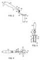
- FIG. 1is a perspective view of the preferred form of an illuminated retractor system according to the present invention
- FIG. 2is an enlarged side view of the preferred form of an illuminated retractor according to the present invention with the optical cable and second elongate section removed for clarity;
- FIG. 3is a front end view of the preferred form of an illuminated retractor according to the present invention with the optical cable and second elongate section removed for clarity;
- FIG. 4is a top view of the preferred form of an illuminated retractor according to the present invention with the optical cable and second elongate section removed for clarity;
- FIG. 5is an enlarged side view of the preferred form of an illuminated retractor according to the present invention with the optical cable removed for clarity;
- FIG. 6is an end view of the preferred form of an illuminated retractor according to the present invention with the optical cable removed for clarity;
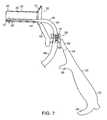
- FIG. 7is an enlarged side view of the preferred form of an illuminated retractor according to the present invention with the first elongate section in cross section;
- FIG. 8is an enlarged sectional view of the connection between the second elongate section and the illumination connector of the embodiment shown in FIG. 1;
- FIG. 9is a perspective view of the preferred form of an obturator used in the illuminated retractor system according to the present invention.
- FIG. 10is a perspective view of the components of an alternate form of an illuminated retractor system according to the present invention.
- FIG. 11is an enlarged side view of an illuminated retractor according to the alternate embodiment of the present invention with the optical cable removed for clarity;
- FIG. 12is an enlarged side view of an illuminated retractor according to the alternate embodiment of the present invention showing the first and second elongate sections and the illumination connector of the illuminated retractor according to the present invention;
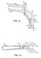
- FIG. 13is an enlarged end view of the proximal end portion of the first elongate section of the alternate embodiment of an illuminated retractor according to the present invention.
- FIG. 14is an enlarged side view, partially in cross section, of an alternate form of an illuminated retractor system according to the present invention.
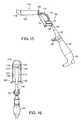
- FIG. 15is a side view of the alternate form of the illuminated retractor according to the embodiment of FIG. 14 with the optical cable removed for clarity;
- FIG. 16is a top view of the alternate form of the illuminated retractor according to the embodiment of FIG. 14 with the optical cable removed for clarity;
- FIG. 17is bottom view of the alternate form of the illuminated retractor according to FIG. 14 with the optical cable and second elongate section removed for clarity;
- FIG. 18is an enlarged end view of the alternate form of the illuminated retractor according to FIG. 14 with the optical cable and second elongate section removed for clarity.
- the present inventionrelates, in general, to an illuminated retractor system and, in particular, to a new and useful illuminated retractor for creating a working space for dissecting instruments in support of a surgical procedure such as rectal examination or for the removal of polyps, fistulas or hemorrhoids or other types of procedures which require the illumination and access to tissue in the rectal area of a patient.
- the diameter of the retractormay be about one-half the length of the first elongate section such that that diameter may be between about 2 cm and 3.5 cm while the length of the first elongate section is preferably about 6 cm.
- the present inventionrelates to an illuminated surgical retractor assembly 10 having a handle member 20 , a first elongate section 30 , a second elongate section 40 , an obturator 50 and an illumination connector assembly 60 .
- the handle member 20is an elongate and generally cylindrical member that has a first bottom handle member end portion 22 and a second top handle member end portion 24 .
- the second handle member end portion 24 of the handle member 20is connected to the illumination connector assembly 60 .
- the preferred combination of retractor mobility and application of retractive or pulling forceoccurs when the angle between the handle member 20 and the lengthwise dimension of the first elongate section 30 is an obtuse angle and more preferably between about 100 and 175 degrees and even more preferably about 110 and 145 degrees and as shown at an angle of about 120 degrees.
- the handle member 20permits the retractor 10 to be moved at nearly any angle with respect to the tissue of the patient.
- the handle member 20 of the retractor 10also preferably includes a finger grip surface 26 that is preferably contoured to be gripped by the hand of a physician to provide more tactile feel and feedback as well as increasing the physician comfort in using and maneuvering the retractor.
- the second handle member end portion 24is preferably rigidly connected to the first rod member 62 of the illumination connector assembly 60 .
- the first rod member 62 and the second rod member 64are aligned generally with the lengthwise dimension of the handle member 20 and the illumination connector assembly 60 interconnect the first elongate section 30 to the handle member 20 .
- the optical cable 66is preferably connected to the illumination connector assembly 60 of the retractor assembly 10 at a location spaced apart from and between the handle member 20 and the first elongate section 30 . Therefore, the handle member 20 is oriented at an obtuse angle relative to the lengthwise dimension of the first elongate section 30 and is spaced apart therefrom so the optical cable 66 does not affect the use of the handle member 20 .
- the connection between the optical cable 66 and the second elongate section 40occurs through the illumination connector 68 of the illumination connector assembly 60 .
- the illumination connector 68is preferably oriented generally perpendicular to the lengthwise dimension of the first elongate section 30 such that the second elongate section 40 preferably includes a portion thereof that extends generally perpendicular to the lengthwise dimension of the first elongate section 30 .
- the optical cable 66is flexible and extends from the illumination connector 68 to a conventional light source (not shown) while not interfering with the view of the physician during the use of the retractor assembly 10 .
- the retractor assembly 10is oriented such that the handle member 20 is positioned downwardly from the first elongate section 30 .
- the illumination connector assembly 60is oriented so that the optical cable 66 extends downwardly from the illumination connector 68 and inwardly from the handle member 20 and the second elongate section 40 is positioned along the lower inner surface of the first elongate section 30 opposite to the operating channel 36 .
- the illumination connector assembly 60also preferably includes a twist connector 70 thereon.
- the twist connector 70allows for the releasable connection of the shaft shaped portion 48 of the second elongate section 40 to the illumination connector 68 in such a manner so as to allow for the transmission of light through the optical cable 66 and into the second elongate section 40 and as well as to provide for the secure attachment therebetween.
- the twist connector 70preferably includes a key and keyway configuration that allows for the secure and quick connection of the second elongate section 40 to the illumination connector 68 .
- the twist connector 70is rotatable a predetermined distance about the illumination connector 68 to provide for the secure positioning of the shaft shaped portion 48 of the second elongate section 40 to the twist connector 70 .
- the twist connectormay be rotatable about three-quarters of a turn between an unlocked position and a locked position to provide a simple and secure method of connection therebetween.
- the first elongate section 30 of the retractor assembly 10is preferably made of a rigid metal or similar material having sufficient strength to penetrate the desired tissue area and support the retracted tissue during use.
- the first elongate section 30preferably has a generally cylindrical shaped configuration with an interior operating channel 36 extending lengthwise therealong.
- the first elongate sectionalso includes a first elongate distal end portion 32 , an enlarged first elongate proximal end portion 34 , a first elongate middle surface 38 and a first elongate inner surface 39 .
- the first elongate inner surface 39includes a post member 35 extending generally inwardly therefrom at a location near the distal end portion 32 of the first elongate section 30 .
- the proximal end portion 34tapers outwardly from the generally cylindrical shape at an obtuse angle relative to the lengthwise dimension of the first elongate section 30 .
- the proximal end portion 34functions to retain the surrounding tissue away from the inner surface 39 of the first elongate section and the somewhat funnel shape also assists in the insertion of the tools into the desired tissue area.
- the operating channel 36preferably extends along the entire length of the first elongate section and has a width of less than about 1 cm so that the portion of the first elongate section that is adjacent to the operating channel 36 supports the surrounding tissue.
- the operating channel 36allows the physician to observe the tissue along the side of the first elongate section and to perform the desired procedure, such as the removal of polyps, by rotating the retractor assembly 10 until the desired tissue is located in the operating channel 36 .
- the first elongate distal end portion 32preferably has a smoothly radiused shape or rounded shape to fit smoothly with the nose cone 52 of the obturator 50 to provide a smooth transition therebetween to ensure that tissue passes smoothly over the distal end portion and the retractor assembly is inserted into the tissue.
- the second elongate section 40has a second elongate distal end portion 42 , a second elongate proximal end portion 44 , a slot member 46 on the distal end portion 42 and a shaft shaped portion 48 on the proximal end thereof.
- the second elongate section between the distal end portion 32 and the proximal end portion 34are preferably generally flat in cross section and extend from the middle surface 38 of the first elongate section 30 to near the distal end portion 32 of the first elongate section 30 .
- the distal end portion 42 of the second elongate section 40is preferably generally flat in cross section and extend from the middle surface 38 of the first elongate section 30 to near the distal end portion 32 of the first elongate section 30 .
- connectionis secured to the inner surface 39 of the first elongate section 30 by inserting the slot surface 46 on the distal end portion 42 into engagement with the post member 35 on the first elongate section 30 .
- connectionis shown as a post and slot configuration, it is anticipated that a variety of other configurations may be used to reliably secure the second elongate section along the inner surface of the first elongate section.
- the second elongate section 40tapers from the generally flat surface into a shaft shaped member 48 .
- the shaft shaped member 48preferably curves to match the curvature and inner dimension of the proximal end portion 34 of the first elongate section 30 .
- This bend portion in the shaft shaped member 48 of the second elongate section 40also allows the transition between the shaft shaped member 48 and the distal end portion 42 of the second elongate section 40 to be surrounded by an optional sleeve member 49 to minimize possible glare from the shaft shaped member 48 and distal portion of the second elongate section.
- the optional sleeve member 49also to protect the shaft shaped member 48 as it curves and extends to the twist connector 70 .
- the transition between the proximal end portion of the second elongate section and the shaft shaped portionmay be shaped to minimize the transmission of light therefrom so that glare from the proximal end portion of the retractor system does not interfere with the physician's use of the present invention.
- the shaft shaped member 48 of the second elongate section 40is preferably spaced apart from the inner surface of the proximal end portion 34 of the first elongate section 30 to reduce the potential for the buildup of heat from the light energy passing through the second elongate section.
- the shaft shaped [portion 49 ] member 48may also include a light shield member [ 37 ] thereon.
- the light shield memberpreferably snaps onto curved portion of the shaft shaped member [ 37 ] to minimize the amount of light transmitted from this portion of the second elongate member.
- the optional shield member [ 37 ]may include a plurality of elongate ribs on the inner diameter thereof to provide an air gap therebetween to minimize the likelihood of the shaft shaped portion overheating and to ensure that the shaft shaped portion is spaced apart from at least a portion of the first elongate section.
- the second elongate section 40is preferably an elongate and rectangular or blade shaped member, although it is anticipated that the second elongate section may also be formed as a single or multiple light fiber member.
- the second elongate sectionis also preferably substantially transparent and is made of a transparent plastic, such as a transparent acryl resin, which has the benefit of being highly resistant to breakage while retaining the ability to flex or deform under pressure and then return undamaged to the original, unstressed configuration.
- the second elongate section 40may also be made of glass or other types of known substantially transparent material in various configurations described herein.
- the second elongate section 40may be connected to the first elongate section 30 in any manner known in the art that is within the level of ordinary skill of one in the surgical field.
- the second elongate sectionmay be chemically bonded to the first elongate 30 through the use of an adhesive or by other chemical bonding means known to one skilled in the art. This chemical bonding may permanently affix the first and second elongate sections 30 , 40 or may preferably allow the first and second elongate sections 30 , 40 to be releasably connected for ease of sterilization of the respective elongate sections 30 , 40 .
- the second elongate sectionis a light fiber element
- the light fiber elementmay be threaded through various retention members located along the lengthwise dimension of the first elongate section.
- the obturator of the present inventionpreferably includes a nose cone 52 on the distal end portion 54 thereof to assist in the tissue expansion and to provide a smooth transition between the nose cone 52 and the distal end portion 32 of the retractor assembly 10 .
- the obturator 50also preferably includes a proximal end portion 56 having an enlarged surface thereon and a second enlarged surface 58 for contact with the proximal end portion 34 of the first elongate section 30 when the obturator 50 is inserted therein.
- the obturator 50also preferably includes an elongate channel area 55 extending along the lengthwise dimension thereof.
- the depth of the channel areais chosen so as to not interfere with the second elongate section 40 when it is positioned along the inner surface 39 of the first elongate section 30 . Additionally, the obturator 50 provides a rounded surface along the operating channel 36 of the first elongate section 30 .
- the distal end portion 52 of the obturator 50is insertable longitudinally into the first elongate section 30 of the retractor such that the channel area 55 on the obturator 50 is aligned with and adjacent to the second elongate section 40 .
- the nose cone 52 of the obturatorpreferably extends a small distance beyond distal end portion 32 of the first elongate section 30 and also provides a curved surface along the lengthwise operating channel 36 in the first elongate section of the retractor to reduce the likelihood that tissue may become hung up on a portion of the retractor.
- the second enlarged surface 58 of the obturatoris a circumferential member that abuts against the proximal end portion of the first elongate section when the nose cone of the obturator extends slightly beyond the distal end portion of the first elongate section to prevent further relative movement between these elements of the retractor assembly.
- the proximal end portion 56 of the obturator 50enables the user to readily insert and remove the obturator from the retractor.
- the first elongate section 30preferably has a cylindrical cross-sectional shape.
- the shape of the first elongate sectionaids in the prevention of unnecessary trauma to the retracted tissue because the outer surface, which is in contact with the tissue when the forces are applied to the retractor 10 , presents no sharp edges that could cause tearing of the tissue and assists in the expansion of the surrounding tissue.
- the shapeaids in distributing the force applied to the retracted tissue by the first elongate section 30 .
- the outer surface of the second elongate section 40may have nearly any geometric cross-section that allows the outer surface to complementarily fit against the inner surface 39 of the first elongate section 30 , as there is no requirement that the inner surface 39 be of a specified shape.
- the only constraint on the shape of the geometric cross-section of the second elongate section 40is that the chosen geometric cross-section should allow the second elongate section 40 to be protected by the first elongate section 30 such that the first and second elongate sections 30 , 40 are preferably operatively interconnected and complementary to each other.
- the first and second elongate sectionsprovide the optimal and desired illumination for the procedure along the length of the first elongate section.
- the first elongate inner surface 39 of the first elongate section 30preferably has a mirrored or reflective surface.
- the inner surface of the second elongate section 40preferably has a machined micro lens surface to refract the light in the desired direction or directions.
- the mirrored surface of the first elongate inner surface 39 and the surface of the inner surfaceact to minimize the loss of the light intensity that is provided to the surgical field by the retractor 10 .
- the second elongate inner surfacemay include a reflective coating or graded dot surface thereon to reflect the light generated through the second elongate section outwardly through the outer surface.
- the second elongate sectionmay be formed so as to specifically direct the light forwardly or towards the proximal end of the retractor to direct the illumination forwardly beyond the distal end portion 32 thereby assisting the user to illuminate the area of interest. Because the second elongate section of the present invention is readily removable, it is anticipated that a variety of second elongate sections may be used, including second elongate sections that are formed to direct the illumination forwardly and/or to one or both sides of the retractor as desired by the user as well as various lengths and/or widths.
- the light energypasses from the light source, through the optical cable 66 and enters the second elongate section 40 at the end portion of the shaft shaped member 48 adjacent to the illumination connector 68 .
- the twist connectoris rotatable to retain the shaft shape portion of the second elongate section securely in the desired position.
- the shaft shape portiondirects the illumination to the second elongate distal end portion 42 of the second elongate section 40 .
- the light energyfills the second elongate section 40 , turning the second elongate section 40 into a “light pipe.”
- the light energyis, in turn, radiated from substantially the entire second elongate section 40 , and particularly from the inner surface of the second elongate section 40 between the distal end portion and proximal end portion of the second elongate section.
- the lightis then directed to the tissue exposed by the retractor 10 . Since substantially the entire length of the second elongate section 40 is illuminated, a large, well illuminated surgical field extends the substantial length of the second elongate section 40 of the retractor 10 . This allows the physician to view the entire field of interest without the use of additional lighting sources.
- FIGS. 10-13are illustrative of a further embodiment of the present invention.
- an insert 75is used to provide a reflective surface for the second elongate section 40 .
- the insert 75is a semi-cylindrical member that also functions to retain the second elongate section 40 in the desired position relative to the first elongate section and maintains the second elongate section in a spaced apart relationship from the sidewall of the first elongate section to ensure that the second elongate section does not inadvertently heat the first elongate section in use.
- the illumination connector 68 of this embodimentis connected directly to the handle member and the handle member is connected to the proximal end portion of the first elongate section.
- FIGS. 14-17are illustrative of a further embodiment of the present invention.
- like numbershave been applied to like elements as described more fully above.
- the handle member 20 and the illumination connector assembly 60are similar to the elements described above and therefore, the description of these elements will not be repeated herein.
- the first elongate section 110 of this embodimentpreferably has a cylindrical cross-sectional shape with a radius of approximately 180 degrees.
- the shape of the first elongate sectionaids in the prevention of unnecessary trauma to the retracted tissue because the outer surface, which is in contact with the tissue when the forces are applied to the retractor 100 , presents no sharp edges that could cause tearing of the tissue and assists in the expansion of the surrounding tissue.
- the shapeaids in distributing the force applied to the retracted tissue by the outer surface of the first elongate section 110 .
- the outer surface of the second elongate section 112may have nearly any geometric cross-section that allows the outer surface to complementarily fit against the inner surface 114 of the first elongate section 110 , as there is no requirement that the inner surface 114 be of a specified shape.
- the only constraint on the shape of the geometric cross-section of the second elongate section 112is that the chosen geometric cross-section should allow the second elongate section 112 to be protected by the first elongate section 110 such that the second elongate section 112 is spaced apart from the retracted tissue.
- first elongate section 110 and the second elongate section 112are preferably operatively interconnected and complementary to each other. Even more preferably, the first and second elongate sections provide the optimal and desired illumination for the procedure along the length of the first elongate section.
- the first elongate section 110 of the retractor assembly 100 of this embodimentis preferably made of a rigid metal, plastic or similar material having sufficient strength to penetrate the desired tissue area and support the retracted tissue during use.
- the first elongate section 110preferably has a generally cylindrical shaped configuration in cross section with an operating channel 116 extending substantially lengthwise along the interior surface thereof.
- the first elongate sectionalso includes a first elongate distal end portion 118 , an enlarged first elongate proximal end portion 120 , a first elongate middle surface 122 and a first elongate inner surface 124 .
- the first elongate inner surface 124includes a post member 126 extending generally upwardly or inwardly therefrom at a location near the distal end portion 118 of the first elongate section 110 . More specifically, the first elongate section 110 includes a generally semi-circular first elongate inner surface 124 having a generally half moon shape in cross section and includes a radius of approximately 180 degrees.
- the rounded distal end portion 118tapers upwardly as compared to the side walls of the elongate middle surface 122 and functions to retain the surrounding tissue away from the inner surface 124 and operating channel 116 of the first elongate section and the generally open proximal end portion also assists in the insertion of the tools into the desired tissue area.
- the operating channel 116preferably extends from the proximal end portion 120 , past the middle section 122 to an upwardly tapered and generally rounded and closed distal end portion 118 .
- the operating channel 116allows the physician to observe the tissue along the open side of the first elongate section and to perform the desired procedure, such as the removal of polyps, by rotating the retractor assembly 100 until the desired tissue is located in the operating channel 116 .
- the first elongate distal end portion 118preferably has a smoothly radiused shape or rounded shape to function in a manner similar to the obturator 50 described above.
- the distal end portion 118is preferably shaped to provide a smooth transition to ensure that tissue passes smoothly over the distal end portion as the retractor assembly is inserted into the tissue. Additionally, as shown, the distal end portion preferably and gradually increases in the cross sectional dimension to further separate the tissue from the operating channel 116 with respect to the lengthwise dimension of the proximal end portion 120 and middle section 122 .
- the second elongate section 112has a second elongate distal end portion 128 , a second elongate proximal end portion 130 , a slot member 132 on the distal end portion 128 and a shaft shaped portion 134 on the proximal end thereof.
- the second elongate section 112 between the distal end portion 128 and the proximal end portion 130is preferably generally flat in cross section and extends from a location distally of the proximal section 120 , past the middle surface 122 to a location near the distal end portion 118 of the first elongate section 110 .
- the distal end portion 128 of the second elongate section 112is secured to the inner surface 124 of the first elongate section 110 by inserting the slot member 132 on the distal end portion 118 into engagement with the post member 126 on the first elongate section 110 .
- the connectionis shown as a post and slot configuration, it is anticipated that a variety of other configurations may be used to reliably secure the second elongate section along the inner surface of the first elongate section.
- the second elongate section 112tapers from the generally flat surface described above into a shaft shaped member 134 .
- the shaft shaped member 134preferably curves to match the curvature and inner dimension of the proximal end portion 120 of the first elongate section 110 .
- This bend portion in the shaft shaped member 134 of the second elongate section 112also allows the transition between the shaft shaped member 134 and the distal end portion 128 of the second elongate section 40 to be surrounded by an optional sleeve member, as described above, to minimize possible glare from the shaft shaped member 134 and distal portion of the second elongate section.
- the optional sleeve memberalso to protect the shaft shaped member 134 as it curves and extends to the twist connector 70 .
- the transition between the proximal end portion of the second elongate section and the shaft shaped portionmay be shaped to minimize the transmission of light therefrom so that glare from the proximal end portion of the retractor system does not interfere with the physician's use of the present invention.
- the shaft shaped member 134 of the second elongate section 112is preferably spaced apart a slight distance from the inner surface of the proximal end portion of the first elongate section 110 to reduce the potential or likelihood of a buildup of heat from the light energy passing through the second elongate section 112 .
- the outer surface and the inner surface of the second sectioncorrespondingly are eliminated as the second elongate section 112 tapers into the shaft shaped member 134 .
- the inner surface 124 of the first elongate section 110preferably has a mirrored or reflective surface.
- the inner surface of the second elongate section 112preferably has a machined micro lens surface to refract the light in the desired direction or directions.
- the mirrored surface of the inner surface 124 and the surface of the second elongate section 112preferably function to minimize the loss of the light intensity that is provided to the surgical field by the retractor 100 .
- the second elongate section 112may include a reflective coating or graded dot surface thereon to reflect the light generated through the second elongate section outwardly through the outer surface.
- the second elongate sectionmay be formed so as to specifically direct the light distally towards the distal end of the retractor or proximally towards the proximal end of the retractor to direct the illumination in a desired direction, such as beyond the distal end portion 114 of the first elongate section thereby assisting the user to illuminate the area of interest.
- the second elongate section of the present inventionis readily removable, it is anticipated that a variety of second elongate sections may be used, including second elongate sections that are formed to direct the illumination forwardly and/or to one or both sides of the retractor as desired by the user as well as various lengths and/or widths.
- the illuminationis directed along substantially the entire length of the first elongate section 110 .
- the light energypasses from the light source, through the optical cable 66 and enters the second elongate section 112 at the end portion of the shaft shaped member 134 adjacent to the illumination connector 68 .
- the twist connectoris rotatable to retain the shaft shape portion of the second elongate section securely in the desired position. The directs the illumination along the second elongate section to the distal end portion 118 of the second elongate section 40 and allows light energy to reflect from the operating channel 116 of the first elongate section 110 .
- the light energyfills the second elongate section 112 , turning the second elongate section 112 into a “light pipe.”
- the light energyis, in turn, radiated from the second elongate section 112 , and particularly from the inner surface of the first elongate section 112 between the distal end portion and proximal end portion of the second elongate section.
- the lightis then directed to the tissue exposed by the retractor 100 . Since substantially the entire length of the second elongate section 110 is illuminated, a large, well illuminated surgical field extends the substantial length of the first elongate section 110 of the retractor 10 . This allows the physician to view the entire field of interest without the use of additional lighting sources.
- the second elongate sectionmay be formed with area of varying light emission intensity so as the allow the physician to choose a second elongate section that emits light in a manner desired by the physician and as needed for a particular procedure.
Landscapes
- Health & Medical Sciences (AREA)
- Life Sciences & Earth Sciences (AREA)
- Surgery (AREA)
- Molecular Biology (AREA)
- General Health & Medical Sciences (AREA)
- Veterinary Medicine (AREA)
- Engineering & Computer Science (AREA)
- Biomedical Technology (AREA)
- Heart & Thoracic Surgery (AREA)
- Medical Informatics (AREA)
- Nuclear Medicine, Radiotherapy & Molecular Imaging (AREA)
- Animal Behavior & Ethology (AREA)
- Pathology (AREA)
- Public Health (AREA)
- Physics & Mathematics (AREA)
- Biophysics (AREA)
- Optics & Photonics (AREA)
- Radiology & Medical Imaging (AREA)
- Oral & Maxillofacial Surgery (AREA)
- Surgical Instruments (AREA)
Abstract
Description
Claims (9)
Priority Applications (3)
| Application Number | Priority Date | Filing Date | Title |
|---|---|---|---|
| US09/639,488US6428473B1 (en) | 2000-02-18 | 2000-08-14 | Illuminated rectal retractor |
| PCT/US2001/004893WO2001060238A1 (en) | 2000-02-18 | 2001-02-15 | Illuminated rectal retractor |
| AU2001238330AAU2001238330A1 (en) | 2000-02-18 | 2001-02-15 | Illuminated rectal retractor |
Applications Claiming Priority (2)
| Application Number | Priority Date | Filing Date | Title |
|---|---|---|---|
| US09/507,229US6497654B1 (en) | 2000-02-18 | 2000-02-18 | Illuminated rectal retractor |
| US09/639,488US6428473B1 (en) | 2000-02-18 | 2000-08-14 | Illuminated rectal retractor |
Related Parent Applications (1)
| Application Number | Title | Priority Date | Filing Date |
|---|---|---|---|
| US09/507,229Continuation-In-PartUS6497654B1 (en) | 2000-02-18 | 2000-02-18 | Illuminated rectal retractor |
Publications (1)
| Publication Number | Publication Date |
|---|---|
| US6428473B1true US6428473B1 (en) | 2002-08-06 |
Family
ID=27055761
Family Applications (1)
| Application Number | Title | Priority Date | Filing Date |
|---|---|---|---|
| US09/639,488Expired - Fee RelatedUS6428473B1 (en) | 2000-02-18 | 2000-08-14 | Illuminated rectal retractor |
Country Status (3)
| Country | Link |
|---|---|
| US (1) | US6428473B1 (en) |
| AU (1) | AU2001238330A1 (en) |
| WO (1) | WO2001060238A1 (en) |
Cited By (49)
| Publication number | Priority date | Publication date | Assignee | Title |
|---|---|---|---|---|
| US20040172105A1 (en)* | 2003-01-31 | 2004-09-02 | Vankoski Stephen J. | Lit retractor |
| US20050085694A1 (en)* | 2003-10-16 | 2005-04-21 | Nakao Naomi L. | Endoscope with open channels |
| US20050165283A1 (en)* | 2003-01-31 | 2005-07-28 | Zimmer Technology, Inc. | Lit retractor |
| US20050182301A1 (en)* | 2003-01-31 | 2005-08-18 | Zimmer Technology, Inc. | Lit retractor |
| JP2006512977A (en)* | 2003-01-21 | 2006-04-20 | エムイーテック エス.アール.エル. | Surgical retractor for hemorrhoid artery |
| US7118528B1 (en)* | 2004-03-16 | 2006-10-10 | Gregory Piskun | Hemorrhoids treatment method and associated instrument assembly including anoscope and cofunctioning tissue occlusion device |
| US20060264706A1 (en)* | 2004-03-16 | 2006-11-23 | Gregory Piskun | Endoluminal treatment method and associated surgical assembly including tissue occlusion device |
| US20070093692A1 (en)* | 2005-10-17 | 2007-04-26 | Leroy Joel J L | Rectoscope Having Light-Emitting Elements |
| US20070118119A1 (en)* | 2005-11-18 | 2007-05-24 | Zimmer Spine, Inc. | Methods and device for dynamic stabilization |
| US20080208188A1 (en)* | 2005-02-14 | 2008-08-28 | Vascular Technologies, Inc. | Probes For Electrical Current Therapy of Tissue, and Methods of Using Same |
| US20080275306A1 (en)* | 2005-10-26 | 2008-11-06 | Carlo Rebuffat | Anoscope for Ano-Rectal Diagnostic and Surgery |
| US20090012562A1 (en)* | 2007-01-02 | 2009-01-08 | Zimmer Spine, Inc. | Spine stiffening device and associated method |
| US20090163770A1 (en)* | 2007-12-21 | 2009-06-25 | Smith & Nephew, Inc. | Cannula |
| US20100041954A1 (en)* | 2006-09-21 | 2010-02-18 | Thd S.P.A. | Device for examining and surgically operating on body cavities, in particular the anal and vaginal cavities |
| US20100145148A1 (en)* | 2008-12-09 | 2010-06-10 | Tyco Healthcare Group, Lp | Anoscope |
| USD623741S1 (en)* | 2009-05-18 | 2010-09-14 | Karl Storz Gmbh & Co. Kg | Dilator |
| USD629516S1 (en)* | 2009-09-29 | 2010-12-21 | Karl Storz Gmbh & Co. Kg | Medical device |
| US20110172491A1 (en)* | 2009-10-01 | 2011-07-14 | Macroplata, Inc. | Detachable balloon catheter |
| US8062217B2 (en) | 2007-01-26 | 2011-11-22 | Theken Spine, Llc | Surgical retractor with removable blades and method of use |
| US8181838B2 (en) | 2008-09-10 | 2012-05-22 | Tyco Healthcare Group Lp | Surgical stapling device |
| US8272555B2 (en) | 2007-03-07 | 2012-09-25 | Tyco Healthcare Group Lp | Stapler for mucosectomy |
| US8506479B2 (en) | 2009-12-16 | 2013-08-13 | Macroplata, Inc. | Substantially rigid and stable endoluminal surgical suite for treating a gastrointestinal lesion |
| US8632458B2 (en) | 2011-10-26 | 2014-01-21 | Macroplata Inc. | Gentle hemorrhoid treatment offering a substantially painless healing |
| US20140058210A1 (en)* | 2003-12-18 | 2014-02-27 | DePuy Synthes Products, LLC | Surgical Retractor Systems and Illuminated Cannulae |
| US20140142394A1 (en)* | 2012-11-20 | 2014-05-22 | Oguz I. Cataltepe | Flexible surgical sheath and multi-part insertion cannula |
| US20140153278A1 (en)* | 2005-05-13 | 2014-06-05 | Invuity, Inc. | Body cavity illumination system |
| US20140316206A1 (en)* | 2010-07-30 | 2014-10-23 | Nilesh R. Vasan | Disposable, self-contained laryngoscope and method of using same |
| US8932211B2 (en) | 2012-06-22 | 2015-01-13 | Macroplata, Inc. | Floating, multi-lumen-catheter retractor system for a minimally-invasive, operative gastrointestinal treatment |
| US8968275B2 (en) | 2010-04-26 | 2015-03-03 | Covidien Lp | Apparatus and method for effecting at least one anatomical structure |
| US9186131B2 (en) | 2009-12-16 | 2015-11-17 | Macroplata, Inc. | Multi-lumen-catheter retractor system for a minimally-invasive, operative gastrointestinal treatment |
| CN105079948A (en)* | 2015-06-30 | 2015-11-25 | 江汉大学 | Anusrectum distention device and system for experimental animals |
| US9204789B2 (en) | 2009-10-08 | 2015-12-08 | Covidien Lp | Asymmetrical anoscope |
| US9254126B2 (en) | 2006-01-05 | 2016-02-09 | DePuy Synthes Products, Inc. | Non-rigid surgical retractor |
| US9565998B2 (en) | 2009-12-16 | 2017-02-14 | Boston Scientific Scimed, Inc. | Multi-lumen-catheter retractor system for a minimally-invasive, operative gastrointestinal treatment |
| US9757109B2 (en) | 2010-12-10 | 2017-09-12 | Illumix Surgical Canada Inc. | Organic light emitting diode illuminated surgical retractor |
| IT201600121462A1 (en)* | 2016-11-30 | 2018-05-30 | Thd Spa | Proctoscope. |
| US10531869B2 (en) | 2009-12-16 | 2020-01-14 | Boston Scientific Scimed, Inc. | Tissue retractor for minimally invasive surgery |
| USD876625S1 (en) | 2018-08-07 | 2020-02-25 | Adroit Surgical, Llc | Laryngoscope |
| US10595711B2 (en) | 2009-12-16 | 2020-03-24 | Boston Scientific Scimed, Inc. | System for a minimally-invasive, operative gastrointestinal treatment |
| US10758116B2 (en) | 2009-12-16 | 2020-09-01 | Boston Scientific Scimed, Inc. | System for a minimally-invasive, operative gastrointestinal treatment |
| US10966701B2 (en) | 2009-12-16 | 2021-04-06 | Boston Scientific Scimed, Inc. | Tissue retractor for minimally invasive surgery |
| US11071534B2 (en) | 2016-12-30 | 2021-07-27 | Boston Scientific Scimed, Inc. | System for a minimally-invasive treatment within a body lumen |
| USRE48850E1 (en) | 2009-12-16 | 2021-12-14 | Boston Scientific Scimed, Inc. | Multi-lumen-catheter retractor system for a minimally-invasive, operative gastrointestinal treatment |
| US11241560B2 (en) | 2017-03-18 | 2022-02-08 | Boston Scientific Scimed, Inc. | System for a minimally-invasive treatment within a body lumen |
| US11832789B2 (en) | 2019-12-13 | 2023-12-05 | Boston Scientific Scimed, Inc. | Devices, systems, and methods for minimally invasive surgery in a body lumen |
| US20240008714A1 (en)* | 2019-03-11 | 2024-01-11 | Integrated Endoscopy, Inc. | Cordless disposable endoscope |
| US12089830B2 (en) | 2009-12-16 | 2024-09-17 | Boston Scientific Scimed, Inc. | Multi-lumen-catheter retractor system for a minimally-invasive, operative gastrointestinal treatment |
| US12376737B1 (en) | 2009-12-16 | 2025-08-05 | Boston Scientific Scimed, Inc. | Tissue retractor for minimally invasive surgery |
| US12440089B2 (en) | 2024-04-23 | 2025-10-14 | Boston Scientific Scimed, Inc. | Endoluminal device with retractor system |
Families Citing this family (6)
| Publication number | Priority date | Publication date | Assignee | Title |
|---|---|---|---|---|
| IT1316922B1 (en)* | 2000-09-01 | 2003-05-13 | Paolo Fontana | OPERATOR ANOSCOPE. |
| GB0517610D0 (en)* | 2005-08-26 | 2005-10-05 | Moredun Res Inst | Speculum |
| DK1929934T3 (en)* | 2006-12-07 | 2016-06-27 | Thd Spa | Medical surgical device for treatment of tyktarmsproktologiske pathologies |
| US8808177B2 (en) | 2008-06-10 | 2014-08-19 | Thd S.P.A. | Medical surgical device for treating coloproctological pathologies |
| CN105343994A (en)* | 2015-12-14 | 2016-02-24 | 丁永斌 | Rectum dilator |
| GB201820602D0 (en) | 2018-12-18 | 2019-01-30 | Artimed As | Medical visual examination and sampling device |
Citations (43)
| Publication number | Priority date | Publication date | Assignee | Title |
|---|---|---|---|---|
| US344984A (en)* | 1886-07-06 | Anal speculum | ||
| US357216A (en)* | 1887-02-08 | Speculum | ||
| US395705A (en)* | 1889-01-08 | Beotal | ||
| US457787A (en)* | 1891-08-18 | Rectal | ||
| US1246340A (en)* | 1916-08-21 | 1917-11-13 | Isaac J Smit | Self-illuminated surgical illuminating-speculum. |
| FR919697A (en) | 1942-04-20 | 1947-03-14 | Improvements to rectoscopes, vaginal specula, proctoscopes, sigmoidoscope and similar instruments | |
| US2482971A (en)* | 1947-07-11 | 1949-09-27 | Golson Kelly Kendall | Self-illuminated transparent proctoscope |
| US2575253A (en)* | 1949-05-16 | 1951-11-13 | Joseph F Bicek | Vaginal speculum |
| US2769441A (en)* | 1954-10-22 | 1956-11-06 | Abramson Daniel Jerome | Speculum |
| US2896611A (en) | 1957-08-08 | 1959-07-28 | Welch Allyn Inc | Orificial instrument construction |
| US2922415A (en)* | 1957-09-05 | 1960-01-26 | Gary J Campagna | Anoscope |
| US3760810A (en) | 1970-12-11 | 1973-09-25 | Hoorn M Van | Surgical ligating instrument of the endoscope type |
| US4052980A (en) | 1976-06-10 | 1977-10-11 | Guenter A. Grams | Triaxial fiberoptic soft tissue retractor |
| FR2361086A1 (en) | 1976-08-13 | 1978-03-10 | Heine Optotech Kg | ENDOSCOPE AND IN PARTICULAR RECTOSCOPE |
| US4562832A (en) | 1984-01-21 | 1986-01-07 | Wilder Joseph R | Medical instrument and light pipe illumination assembly |
| US4597030A (en) | 1985-01-31 | 1986-06-24 | American Hospital Supply Corporation | Surgical illuminator |
| US4690132A (en)* | 1985-04-09 | 1987-09-01 | Izhak Bayer | Endoscope particularly useful as an anoscope |
| US4765701A (en) | 1987-01-30 | 1988-08-23 | Poly-Optical Products, Inc. | Illuminator optical fiber rod |
| US4834067A (en)* | 1986-05-30 | 1989-05-30 | Block Irving R | Instrument for internal hemorrhoidectomy |
| US4884559A (en)* | 1987-12-04 | 1989-12-05 | Collins Jason H | Surgical speculum |
| US4996976A (en) | 1988-08-17 | 1991-03-05 | Masahiko Nakagawa | Tongue depressor with illuminating means |
| US5005108A (en) | 1989-02-10 | 1991-04-02 | Lumitex, Inc. | Thin panel illuminator |
| US5035232A (en) | 1987-10-24 | 1991-07-30 | Aesculap Ag | Retractor |
| US5249568A (en)* | 1991-06-28 | 1993-10-05 | Logix, Inc. | Body cavity introducer |
| US5503617A (en) | 1994-07-19 | 1996-04-02 | Jako; Geza J. | Retractor and method for direct access endoscopic surgery |
| US5514076A (en) | 1994-01-27 | 1996-05-07 | Flexmedics Corporation | Surgical retractor |
| US5514077A (en) | 1994-07-05 | 1996-05-07 | Rabban; Philipp | Surgical retractor |
| WO1997013462A1 (en) | 1995-10-10 | 1997-04-17 | Genzyme Corporation | Radially adjustable surgical instrument for heart surgery |
| US5667480A (en) | 1995-10-20 | 1997-09-16 | Ethicon Endo-Surgery, Inc. | Method and devices for endoscopic vessel harvesting |
| US5716329A (en)* | 1996-09-30 | 1998-02-10 | Dieter; Michael A. | Disposable expandable speculum |
| US5730748A (en) | 1995-05-19 | 1998-03-24 | General Surgical Innovations, Inc. | Methods and devices for blood vessel harvesting |
| US5776159A (en) | 1996-10-03 | 1998-07-07 | General Surgical Innovations, Inc. | Combination dissector and expander |
| US5785648A (en)* | 1996-10-09 | 1998-07-28 | David Min, M.D., Inc. | Speculum |
| US5797947A (en) | 1995-05-19 | 1998-08-25 | General Surgical Innovations, Inc. | Methods and devices for harvesting blood vessels with balloons |
| US5827318A (en) | 1990-03-02 | 1998-10-27 | General Surgical Innovations, Inc. | Method of dissecting tissue layers |
| US5846249A (en)* | 1996-02-07 | 1998-12-08 | Pinotage, Llc | Video gynecological examination apparatus |
| WO1999001696A1 (en) | 1997-07-02 | 1999-01-14 | Lumitex, Inc. | Light delivery system and applications thereof |
| US5904650A (en) | 1997-09-19 | 1999-05-18 | Genzyme Corporation | Ball joint retractor |
| US5913818A (en) | 1997-06-02 | 1999-06-22 | General Surgical Innovations, Inc. | Vascular retractor |
| US5921919A (en) | 1997-05-30 | 1999-07-13 | Origin Medsystems, Inc. | Perivascular self-retaining retractor and method |
| US5967971A (en) | 1998-04-14 | 1999-10-19 | Bolser; Jeffrey William | Surgical instrument |
| WO1999056633A1 (en) | 1998-05-01 | 1999-11-11 | Genzyme Corporation | Illuminated surgical retractor |
| US6033361A (en) | 1997-06-02 | 2000-03-07 | General Surgical Innovations, Inc. | Vascular retractor |
- 2000
- 2000-08-14USUS09/639,488patent/US6428473B1/ennot_activeExpired - Fee Related
- 2001
- 2001-02-15WOPCT/US2001/004893patent/WO2001060238A1/enactiveApplication Filing
- 2001-02-15AUAU2001238330Apatent/AU2001238330A1/ennot_activeAbandoned
Patent Citations (46)
| Publication number | Priority date | Publication date | Assignee | Title |
|---|---|---|---|---|
| US344984A (en)* | 1886-07-06 | Anal speculum | ||
| US357216A (en)* | 1887-02-08 | Speculum | ||
| US395705A (en)* | 1889-01-08 | Beotal | ||
| US457787A (en)* | 1891-08-18 | Rectal | ||
| US1246340A (en)* | 1916-08-21 | 1917-11-13 | Isaac J Smit | Self-illuminated surgical illuminating-speculum. |
| FR919697A (en) | 1942-04-20 | 1947-03-14 | Improvements to rectoscopes, vaginal specula, proctoscopes, sigmoidoscope and similar instruments | |
| US2482971A (en)* | 1947-07-11 | 1949-09-27 | Golson Kelly Kendall | Self-illuminated transparent proctoscope |
| US2575253A (en)* | 1949-05-16 | 1951-11-13 | Joseph F Bicek | Vaginal speculum |
| US2769441A (en)* | 1954-10-22 | 1956-11-06 | Abramson Daniel Jerome | Speculum |
| US2896611A (en) | 1957-08-08 | 1959-07-28 | Welch Allyn Inc | Orificial instrument construction |
| US2922415A (en)* | 1957-09-05 | 1960-01-26 | Gary J Campagna | Anoscope |
| US3760810A (en) | 1970-12-11 | 1973-09-25 | Hoorn M Van | Surgical ligating instrument of the endoscope type |
| US4052980A (en) | 1976-06-10 | 1977-10-11 | Guenter A. Grams | Triaxial fiberoptic soft tissue retractor |
| FR2361086A1 (en) | 1976-08-13 | 1978-03-10 | Heine Optotech Kg | ENDOSCOPE AND IN PARTICULAR RECTOSCOPE |
| US4562832A (en) | 1984-01-21 | 1986-01-07 | Wilder Joseph R | Medical instrument and light pipe illumination assembly |
| US4597030A (en) | 1985-01-31 | 1986-06-24 | American Hospital Supply Corporation | Surgical illuminator |
| US4690132A (en)* | 1985-04-09 | 1987-09-01 | Izhak Bayer | Endoscope particularly useful as an anoscope |
| US4834067A (en)* | 1986-05-30 | 1989-05-30 | Block Irving R | Instrument for internal hemorrhoidectomy |
| US4765701A (en) | 1987-01-30 | 1988-08-23 | Poly-Optical Products, Inc. | Illuminator optical fiber rod |
| US5035232A (en) | 1987-10-24 | 1991-07-30 | Aesculap Ag | Retractor |
| US4884559A (en)* | 1987-12-04 | 1989-12-05 | Collins Jason H | Surgical speculum |
| US4996976A (en) | 1988-08-17 | 1991-03-05 | Masahiko Nakagawa | Tongue depressor with illuminating means |
| US5005108A (en) | 1989-02-10 | 1991-04-02 | Lumitex, Inc. | Thin panel illuminator |
| US5827318A (en) | 1990-03-02 | 1998-10-27 | General Surgical Innovations, Inc. | Method of dissecting tissue layers |
| US5249568A (en)* | 1991-06-28 | 1993-10-05 | Logix, Inc. | Body cavity introducer |
| US5514076A (en) | 1994-01-27 | 1996-05-07 | Flexmedics Corporation | Surgical retractor |
| US5514077A (en) | 1994-07-05 | 1996-05-07 | Rabban; Philipp | Surgical retractor |
| US5503617A (en) | 1994-07-19 | 1996-04-02 | Jako; Geza J. | Retractor and method for direct access endoscopic surgery |
| US5730748A (en) | 1995-05-19 | 1998-03-24 | General Surgical Innovations, Inc. | Methods and devices for blood vessel harvesting |
| US5853417A (en) | 1995-05-19 | 1998-12-29 | General Surgical Innovations, Inc. | Methods and devices for blood vessel harvesting |
| US5797947A (en) | 1995-05-19 | 1998-08-25 | General Surgical Innovations, Inc. | Methods and devices for harvesting blood vessels with balloons |
| WO1997013462A1 (en) | 1995-10-10 | 1997-04-17 | Genzyme Corporation | Radially adjustable surgical instrument for heart surgery |
| US5722934A (en) | 1995-10-20 | 1998-03-03 | Ethicon Endo-Surgery, Inc. | Method and devices for endoscopoic vessel harvesting |
| US5725479A (en) | 1995-10-20 | 1998-03-10 | Ethicon Endo-Surgery, Inc. | Method and devices for endoscopic vessel harvesting |
| US5667480A (en) | 1995-10-20 | 1997-09-16 | Ethicon Endo-Surgery, Inc. | Method and devices for endoscopic vessel harvesting |
| US5846249A (en)* | 1996-02-07 | 1998-12-08 | Pinotage, Llc | Video gynecological examination apparatus |
| US5716329A (en)* | 1996-09-30 | 1998-02-10 | Dieter; Michael A. | Disposable expandable speculum |
| US5776159A (en) | 1996-10-03 | 1998-07-07 | General Surgical Innovations, Inc. | Combination dissector and expander |
| US5785648A (en)* | 1996-10-09 | 1998-07-28 | David Min, M.D., Inc. | Speculum |
| US5921919A (en) | 1997-05-30 | 1999-07-13 | Origin Medsystems, Inc. | Perivascular self-retaining retractor and method |
| US5913818A (en) | 1997-06-02 | 1999-06-22 | General Surgical Innovations, Inc. | Vascular retractor |
| US6033361A (en) | 1997-06-02 | 2000-03-07 | General Surgical Innovations, Inc. | Vascular retractor |
| WO1999001696A1 (en) | 1997-07-02 | 1999-01-14 | Lumitex, Inc. | Light delivery system and applications thereof |
| US5904650A (en) | 1997-09-19 | 1999-05-18 | Genzyme Corporation | Ball joint retractor |
| US5967971A (en) | 1998-04-14 | 1999-10-19 | Bolser; Jeffrey William | Surgical instrument |
| WO1999056633A1 (en) | 1998-05-01 | 1999-11-11 | Genzyme Corporation | Illuminated surgical retractor |
Non-Patent Citations (13)
| Title |
|---|
| Auto Suture Company, The Mini-Harvest System for Minimally Invasive Saphenous Vein Harvesting, 1996. |
| Design News, Medical Plastic/Cover Story, Bypass Surgery Made Easier, Disposable Instruments, made from standard plastics, key to minimally invasive procedure for extracting veins, Gary Chamberlain, Senior Editor, pp. 57-58; 60, 62 (Jan. 6, 1997). |
| Dimitri, W. R. et al., A Quick and Atraumatic Method of Autologous Vein Harvesting Using the Subcutaneous Extraluminal Dissector, J. Cardiovasc. Surg., vol. 28, pp. 103-111 (1987). |
| Dregelid, E. et al., Endothelial Cell Injury in Human Saphenous Veins After Manipulation and Tweezer Grasping, J. Cardiovasc. Surg., vol. 29, pp. 464-469 (1988). |
| Gundry, Steven R., et al., Optimal Preparation Techniques for Human Saphenous Vein Grafts, Surgery, No. 6, pp. 785-794 (Dec. 1980). |
| Hauer, G. et al., Endoscopic Subfascial Discission of Perforating Veins, Surg. Endosc., vol. 2, pp. 5-12 (1988). |
| Lee, John, Surgical Physician Assistant, Minimally Invasive Vein Harvesting, Nov./Dec. 1996, pp. 26-32. |
| Meldrum-Hanna, W. et al., Long Saphenous Vein Harvesting, Aust.N.Z. J.Surg., vol. 56, pp. 923-924 (1986). |
| Moazami, Nader et al., Minimally Invasive Greater Saphenous Vein Harvesting for Coronary Artery Bypass Surgery, Surgical Rounds, pp. 94-97 (Mar. 1997). |
| Rashid, A. et al., Subcutaneous Technique for Saphenous Vein Harvest, The Annals of Thoracic Surgery, vol. 37, No. 2, pp. 169-170 IFeb. 1984). |
| Snowden Pencer DSP, EndoCABG System, Innovative Instrumentation for Endoscopic Coronary Artery Bypass Grafting, 1996. |
| Snowden Pencer DSP, The Diamond-Line of Surgical Instruments Brochure, Tebbetts EndoPlastic Instrument System, 1995. |
| Wheatley, D.J.,Autocronary Bypass Grafting Techniques, Surgery of Coronary Artery Disease, pp. 348-349 (Date Unknown). |
Cited By (132)
| Publication number | Priority date | Publication date | Assignee | Title |
|---|---|---|---|---|
| JP2006512977A (en)* | 2003-01-21 | 2006-04-20 | エムイーテック エス.アール.エル. | Surgical retractor for hemorrhoid artery |
| US7503894B2 (en) | 2003-01-31 | 2009-03-17 | Zimmer Technology, Inc. | Lit retractor |
| US20050165283A1 (en)* | 2003-01-31 | 2005-07-28 | Zimmer Technology, Inc. | Lit retractor |
| US20050182301A1 (en)* | 2003-01-31 | 2005-08-18 | Zimmer Technology, Inc. | Lit retractor |
| US20040172105A1 (en)* | 2003-01-31 | 2004-09-02 | Vankoski Stephen J. | Lit retractor |
| US7371213B2 (en) | 2003-01-31 | 2008-05-13 | Zimmer Technology, Inc. | Lit retractor |
| US20050085694A1 (en)* | 2003-10-16 | 2005-04-21 | Nakao Naomi L. | Endoscope with open channels |
| US7762949B2 (en)* | 2003-10-16 | 2010-07-27 | Granit Medical Innovation, Llc | Endoscope with open channels |
| US10869657B2 (en)* | 2003-12-18 | 2020-12-22 | DePuy Synthes Products, Inc. | Surgical retractor systems and illuminated cannulae |
| US20140058210A1 (en)* | 2003-12-18 | 2014-02-27 | DePuy Synthes Products, LLC | Surgical Retractor Systems and Illuminated Cannulae |
| US9867633B2 (en) | 2004-03-16 | 2018-01-16 | Covidien Lp | Endoluminal treatment method and associated surgical assembly including tissue occlusion device |
| US9039601B2 (en) | 2004-03-16 | 2015-05-26 | Macroplata, Inc. | Endoluminal treatment method and associated surgical assembly including tissue occlusion device |
| US8100822B2 (en) | 2004-03-16 | 2012-01-24 | Macroplata Systems, Llc | Anoscope for treating hemorrhoids without the trauma of cutting or the use of an endoscope |
| US10245061B2 (en) | 2004-03-16 | 2019-04-02 | Covidien Lp | Treatment method including tissue occlusion device |
| US7118528B1 (en)* | 2004-03-16 | 2006-10-10 | Gregory Piskun | Hemorrhoids treatment method and associated instrument assembly including anoscope and cofunctioning tissue occlusion device |
| US10485567B2 (en) | 2004-03-16 | 2019-11-26 | Boston Scientific Scimed, Inc. | Endoluminal treatment method and associated surgical assembly |
| US20100010297A1 (en)* | 2004-03-16 | 2010-01-14 | Macroplata Systems, Llc | Endoluminal treatment method and associated surgical assembly including tissue occlusion device |
| US20100010296A1 (en)* | 2004-03-16 | 2010-01-14 | Macroplata Systems, Llc | Endoluminal treatment method and associated surgical assembly including tissue occlusion device |
| US8715166B2 (en) | 2004-03-16 | 2014-05-06 | Macroplata Inc. | Gentle method of treating a hemorrhoid |
| US20100056870A1 (en)* | 2004-03-16 | 2010-03-04 | Macroplata Systems, Llc | Endoluminal treatment method and associated surgical assembly including tissue occlusion device |
| US9661984B2 (en) | 2004-03-16 | 2017-05-30 | Macroplata, Inc. | Endoluminal treatment method and associated surgical assembly |
| US20060264706A1 (en)* | 2004-03-16 | 2006-11-23 | Gregory Piskun | Endoluminal treatment method and associated surgical assembly including tissue occlusion device |
| US10492815B2 (en) | 2004-03-16 | 2019-12-03 | Boston Scientific Scimed, Inc. | Endoluminal treatment method and associated surgical assembly |
| US8430808B2 (en) | 2004-03-16 | 2013-04-30 | Maeroplata, Inc. | Endoscopic method and device for avoiding cutting of rectal tissue in the treatment of hemorrhoids |
| US8131380B2 (en)* | 2005-02-14 | 2012-03-06 | Vascular Technologies, Inc. | Probes for electrical current therapy of tissue, and methods of using same |
| US20080208188A1 (en)* | 2005-02-14 | 2008-08-28 | Vascular Technologies, Inc. | Probes For Electrical Current Therapy of Tissue, and Methods of Using Same |
| US20140153278A1 (en)* | 2005-05-13 | 2014-06-05 | Invuity, Inc. | Body cavity illumination system |
| US10912453B2 (en)* | 2005-05-13 | 2021-02-09 | Invuity, Inc. | Body cavity illumination system |
| US11903567B2 (en) | 2005-05-13 | 2024-02-20 | Invuity, Inc. | Body cavity illumination system |
| US12178463B2 (en) | 2005-08-05 | 2024-12-31 | Boston Scientific Scimed, Inc. | Endoluminal treatment method and associated surgical assembly including tissue occlusion device |
| US7967746B2 (en)* | 2005-10-17 | 2011-06-28 | Karl Storz Gmbh & Co. Kg | Rectoscope having light-emitting elements |
| US20070093692A1 (en)* | 2005-10-17 | 2007-04-26 | Leroy Joel J L | Rectoscope Having Light-Emitting Elements |
| US8337401B2 (en) | 2005-10-26 | 2012-12-25 | Covidien Ag | Anoscope for ano-rectal diagnostic and surgery |
| US9307896B2 (en) | 2005-10-26 | 2016-04-12 | Covidien Ag | Anoscope for ano-rectal diagnostic and surgery |
| US20080275306A1 (en)* | 2005-10-26 | 2008-11-06 | Carlo Rebuffat | Anoscope for Ano-Rectal Diagnostic and Surgery |
| US8956282B2 (en) | 2005-10-26 | 2015-02-17 | Covidien Ag | Anoscope for ano-rectal diagnostic and surgery |
| US8740781B2 (en) | 2005-10-26 | 2014-06-03 | Covidien Ag | Anoscope for ano-rectal diagnostic and surgery |
| US20070118119A1 (en)* | 2005-11-18 | 2007-05-24 | Zimmer Spine, Inc. | Methods and device for dynamic stabilization |
| US9254126B2 (en) | 2006-01-05 | 2016-02-09 | DePuy Synthes Products, Inc. | Non-rigid surgical retractor |
| US8894572B2 (en)* | 2006-09-21 | 2014-11-25 | Thd S.P.A. | Device for examining and surgically operating on body cavities, in particular the anal and vaginal cavities |
| US9480471B2 (en)* | 2006-09-21 | 2016-11-01 | Thd S.P.A. | Device for examining and surgically operating on body cavities, in particular the anal and vaginal cavities |
| US20150038799A1 (en)* | 2006-09-21 | 2015-02-05 | Thd S.P.A. | Device for examining and surgically operating on body cavities, in particular the anal and vaginal cavities |
| US20100041954A1 (en)* | 2006-09-21 | 2010-02-18 | Thd S.P.A. | Device for examining and surgically operating on body cavities, in particular the anal and vaginal cavities |
| US20090030464A1 (en)* | 2007-01-02 | 2009-01-29 | Zimmer Spine, Inc. | Spine stiffening device and associated method |
| US8029544B2 (en) | 2007-01-02 | 2011-10-04 | Zimmer Spine, Inc. | Spine stiffening device |
| US8206422B2 (en) | 2007-01-02 | 2012-06-26 | Zimmer Spine, Inc. | Spine stiffening device and associated method |
| US20090012562A1 (en)* | 2007-01-02 | 2009-01-08 | Zimmer Spine, Inc. | Spine stiffening device and associated method |
| US8062217B2 (en) | 2007-01-26 | 2011-11-22 | Theken Spine, Llc | Surgical retractor with removable blades and method of use |
| US10568631B2 (en) | 2007-03-07 | 2020-02-25 | Covidien Lp | Stapler for mucosectomy |
| US8272555B2 (en) | 2007-03-07 | 2012-09-25 | Tyco Healthcare Group Lp | Stapler for mucosectomy |
| US8875974B2 (en) | 2007-03-07 | 2014-11-04 | Covidien Ag | Stapler for mucosectomy |
| US9883862B2 (en) | 2007-03-07 | 2018-02-06 | Covidien Lp | Stapler for mucosectomy |
| US8684251B2 (en) | 2007-03-07 | 2014-04-01 | Covidien Ag | Stapler for mucosectomy |
| US9119621B2 (en) | 2007-03-07 | 2015-09-01 | Covidien Ag | Stapler for mucosectomy |
| US10660632B2 (en)* | 2007-12-21 | 2020-05-26 | Smith & Nephew, Inc. | Cannula |
| US20090163770A1 (en)* | 2007-12-21 | 2009-06-25 | Smith & Nephew, Inc. | Cannula |
| US9358006B2 (en) | 2008-09-10 | 2016-06-07 | Covidien Lp | Surgical stapling device |
| US9113871B2 (en) | 2008-09-10 | 2015-08-25 | Covidien Lp | Surgical stapling device |
| US8360295B2 (en) | 2008-09-10 | 2013-01-29 | Covidien Lp | Surgical stapling device |
| US8343185B2 (en) | 2008-09-10 | 2013-01-01 | Covidien Lp | Surgical stapling device |
| US8181838B2 (en) | 2008-09-10 | 2012-05-22 | Tyco Healthcare Group Lp | Surgical stapling device |
| US20160038015A1 (en)* | 2008-12-09 | 2016-02-11 | Covidien Lp | Anoscope |
| US9636010B2 (en)* | 2008-12-09 | 2017-05-02 | Covidien Lp | Anoscope |
| US9192291B2 (en)* | 2008-12-09 | 2015-11-24 | Covidien Lp | Anoscope |
| US20100145148A1 (en)* | 2008-12-09 | 2010-06-10 | Tyco Healthcare Group, Lp | Anoscope |
| US8348837B2 (en) | 2008-12-09 | 2013-01-08 | Covidien Lp | Anoscope |
| US8926505B2 (en) | 2008-12-09 | 2015-01-06 | Covidien Lp | Anoscope |
| US20150080656A1 (en)* | 2008-12-09 | 2015-03-19 | Covidien Lp | Anoscope |
| USD623741S1 (en)* | 2009-05-18 | 2010-09-14 | Karl Storz Gmbh & Co. Kg | Dilator |
| USD629516S1 (en)* | 2009-09-29 | 2010-12-21 | Karl Storz Gmbh & Co. Kg | Medical device |
| US20110172491A1 (en)* | 2009-10-01 | 2011-07-14 | Macroplata, Inc. | Detachable balloon catheter |
| US9204789B2 (en) | 2009-10-08 | 2015-12-08 | Covidien Lp | Asymmetrical anoscope |
| USRE48729E1 (en) | 2009-12-16 | 2021-09-14 | Boston Scientific Scimed, Inc. | Endoluminal system for gastrointestinal treatment |
| USRE48750E1 (en) | 2009-12-16 | 2021-09-28 | Boston Scientific Scimed, Inc. | Substaintially rigid and stable endoluminal surgical suite for treating a gastrointestinal lesion |
| US9554690B2 (en) | 2009-12-16 | 2017-01-31 | Boston Scientific Scimed, Inc. | Endoluminal device with retractor system |
| US9655506B2 (en) | 2009-12-16 | 2017-05-23 | Boston Scientific Scimed, Inc. | Endoluminal device with retractor system |
| US12376737B1 (en) | 2009-12-16 | 2025-08-05 | Boston Scientific Scimed, Inc. | Tissue retractor for minimally invasive surgery |
| US9713416B2 (en) | 2009-12-16 | 2017-07-25 | Boston Scientific Scimed, Inc. | Endoluminal system and method for gastrointestinal treatment |
| US9737194B2 (en) | 2009-12-16 | 2017-08-22 | Boston Scientific Scimed, Inc. | Endoluminal system for gastrointestinal treatment |
| US12089830B2 (en) | 2009-12-16 | 2024-09-17 | Boston Scientific Scimed, Inc. | Multi-lumen-catheter retractor system for a minimally-invasive, operative gastrointestinal treatment |
| US12059138B2 (en) | 2009-12-16 | 2024-08-13 | Boston Scientific Scimed, Inc. | System for a minimally-invasive, operative gastrointestinal treatment background |
| US11992194B2 (en) | 2009-12-16 | 2024-05-28 | Boston Scientific Scimed, Inc. | Substantially rigid and stable endoluminal surgical suite for treating a gastrointestinal lesion |
| US9186130B2 (en) | 2009-12-16 | 2015-11-17 | Macroplata Inc. | Endoluminal system for gastrointestinal treatment |
| US11330976B2 (en) | 2009-12-16 | 2022-05-17 | Boston Scientific Scimed, Inc. | Substantially rigid and stable endoluminal surgical suite for treating a gastrointestinal lesion |
| US11272836B2 (en) | 2009-12-16 | 2022-03-15 | Boston Scientific Scimed, Inc. | Substantially rigid and stable endoluminal surgical suite for treating a gastrointestinal lesion |
| USRE48850E1 (en) | 2009-12-16 | 2021-12-14 | Boston Scientific Scimed, Inc. | Multi-lumen-catheter retractor system for a minimally-invasive, operative gastrointestinal treatment |
| USRE48800E1 (en) | 2009-12-16 | 2021-11-02 | Boston Scientific Scimed, Inc. | Endoluminal system for gastrointestinal treatment |
| US9565998B2 (en) | 2009-12-16 | 2017-02-14 | Boston Scientific Scimed, Inc. | Multi-lumen-catheter retractor system for a minimally-invasive, operative gastrointestinal treatment |
| US11122970B2 (en) | 2009-12-16 | 2021-09-21 | Boston Scientific Scimed | Substantially rigid and stable endoluminal surgical suite for treating a gastrointestinal lesion |
| US9186131B2 (en) | 2009-12-16 | 2015-11-17 | Macroplata, Inc. | Multi-lumen-catheter retractor system for a minimally-invasive, operative gastrointestinal treatment |
| USRE48684E1 (en) | 2009-12-16 | 2021-08-17 | Boston Scientific Scimed, Inc. | Endoluminal device with retractor system |
| US10517580B2 (en) | 2009-12-16 | 2019-12-31 | Boston Scientific Scimed, Inc. | Multi-lumen-catheter retractor system for a minimally invasive, operative gastrointestinal treatment |
| US10531869B2 (en) | 2009-12-16 | 2020-01-14 | Boston Scientific Scimed, Inc. | Tissue retractor for minimally invasive surgery |
| US10537315B2 (en) | 2009-12-16 | 2020-01-21 | Boston Scientific Scimed, Inc. | Multi-lumen-catheter retractor system for a minimally-invasive, operative gastrointestinal treatment |
| US10537238B2 (en) | 2009-12-16 | 2020-01-21 | Boston Scientific Scimed, Inc. | Substantially rigid and stable endoluminal surgical suite for treating a gastrointestinal lesion |
| US10548582B2 (en) | 2009-12-16 | 2020-02-04 | Boston Scientific Scimed, Inc. | Multi-lumen-catheter retractor system for a minimally-invasive, operative gastrointestinal treatment |
| USRE48597E1 (en) | 2009-12-16 | 2021-06-22 | Boston Scientific Scimed, Inc. | Endoluminal system and method for gastrointestinal treatment |
| US8506479B2 (en) | 2009-12-16 | 2013-08-13 | Macroplata, Inc. | Substantially rigid and stable endoluminal surgical suite for treating a gastrointestinal lesion |
| US10588489B2 (en) | 2009-12-16 | 2020-03-17 | Boston Scientific Scimed, Inc. | Endoluminal system and method for gastrointestinal treatment |
| US10588504B2 (en) | 2009-12-16 | 2020-03-17 | Boston Scientific Scimed, Inc. | Multi-lumen-catheter system for a minimally-invasive treatment |
| US10595711B2 (en) | 2009-12-16 | 2020-03-24 | Boston Scientific Scimed, Inc. | System for a minimally-invasive, operative gastrointestinal treatment |
| US10595841B2 (en) | 2009-12-16 | 2020-03-24 | Boston Scientific Scimed, Inc. | Multi-lumen-catheter retractor system for a minimally-invasive, operative gastrointestinal treatment |
| US10966701B2 (en) | 2009-12-16 | 2021-04-06 | Boston Scientific Scimed, Inc. | Tissue retractor for minimally invasive surgery |
| US9125636B2 (en) | 2009-12-16 | 2015-09-08 | Macroplata, Inc. | Endoluminal device with retractor system |
| US10716464B2 (en) | 2009-12-16 | 2020-07-21 | Boston Scientific Scimed, Inc. | Endoluminal device with retractor system |
| US10758116B2 (en) | 2009-12-16 | 2020-09-01 | Boston Scientific Scimed, Inc. | System for a minimally-invasive, operative gastrointestinal treatment |
| USRE48485E1 (en) | 2009-12-16 | 2021-03-30 | Boston Scientific Scimed, Inc. | Endoluminal device with retractor system |
| US9161746B2 (en) | 2009-12-16 | 2015-10-20 | Macroplata, Inc. | Substaintially rigid and stable endoluminal surgical suite for treating a gastrointestinal lesion |
| US11992180B2 (en) | 2009-12-18 | 2024-05-28 | Boston Scientific Scimed, Inc. | Endoluminal device with retractor system |
| US9833250B2 (en) | 2010-04-26 | 2017-12-05 | Covidien Lp | Apparatus and method for effecting at least one anatomical structure |
| US9883879B2 (en) | 2010-04-26 | 2018-02-06 | Covidien Lp | Apparatus for treating hemorrhoids |
| US8968275B2 (en) | 2010-04-26 | 2015-03-03 | Covidien Lp | Apparatus and method for effecting at least one anatomical structure |
| US9949631B2 (en) | 2010-04-26 | 2018-04-24 | Covidien Lp | Gentle hemorrhoid treatment offering a substantially painless healing |
| US9011317B2 (en) | 2010-04-26 | 2015-04-21 | Covidien Lp | Gentle hemorrhoid treatment offering a substantially painless healing |
| US9289114B2 (en)* | 2010-07-30 | 2016-03-22 | Nilesh R. Vasan | Disposable, self-contained laryngoscope and method of using same |
| US20140316206A1 (en)* | 2010-07-30 | 2014-10-23 | Nilesh R. Vasan | Disposable, self-contained laryngoscope and method of using same |
| US9757109B2 (en) | 2010-12-10 | 2017-09-12 | Illumix Surgical Canada Inc. | Organic light emitting diode illuminated surgical retractor |
| US8632458B2 (en) | 2011-10-26 | 2014-01-21 | Macroplata Inc. | Gentle hemorrhoid treatment offering a substantially painless healing |
| US8932211B2 (en) | 2012-06-22 | 2015-01-13 | Macroplata, Inc. | Floating, multi-lumen-catheter retractor system for a minimally-invasive, operative gastrointestinal treatment |
| US10646690B2 (en)* | 2012-11-20 | 2020-05-12 | University Of Massachusetts | Flexible surgical sheath and multi-part insertion cannula |
| US20140142394A1 (en)* | 2012-11-20 | 2014-05-22 | Oguz I. Cataltepe | Flexible surgical sheath and multi-part insertion cannula |
| CN105079948A (en)* | 2015-06-30 | 2015-11-25 | 江汉大学 | Anusrectum distention device and system for experimental animals |
| IT201600121462A1 (en)* | 2016-11-30 | 2018-05-30 | Thd Spa | Proctoscope. |
| EP3329834A1 (en)* | 2016-11-30 | 2018-06-06 | THD S.p.A. | Proctoscope |
| US10463244B2 (en) | 2016-11-30 | 2019-11-05 | Thd S.P.A. | Proctoscope |
| US11071534B2 (en) | 2016-12-30 | 2021-07-27 | Boston Scientific Scimed, Inc. | System for a minimally-invasive treatment within a body lumen |
| US11241560B2 (en) | 2017-03-18 | 2022-02-08 | Boston Scientific Scimed, Inc. | System for a minimally-invasive treatment within a body lumen |
| USD876625S1 (en) | 2018-08-07 | 2020-02-25 | Adroit Surgical, Llc | Laryngoscope |
| US20240008714A1 (en)* | 2019-03-11 | 2024-01-11 | Integrated Endoscopy, Inc. | Cordless disposable endoscope |
| US12239286B2 (en)* | 2019-03-11 | 2025-03-04 | Integrated Endoscopy, Inc. | Cordless disposable endoscope |
| US11832789B2 (en) | 2019-12-13 | 2023-12-05 | Boston Scientific Scimed, Inc. | Devices, systems, and methods for minimally invasive surgery in a body lumen |
| US12440089B2 (en) | 2024-04-23 | 2025-10-14 | Boston Scientific Scimed, Inc. | Endoluminal device with retractor system |
Also Published As
| Publication number | Publication date |
|---|---|
| AU2001238330A1 (en) | 2001-08-27 |
| WO2001060238A1 (en) | 2001-08-23 |
Similar Documents
| Publication | Publication Date | Title |
|---|---|---|
| US6428473B1 (en) | Illuminated rectal retractor | |
| US6497654B1 (en) | Illuminated rectal retractor | |
| US6554768B1 (en) | Illuminated deep pelvic retractor | |
| US6322499B1 (en) | Pivotal and illuminated saphenous vein retractor | |
| US7470269B2 (en) | Ophthalmic surgery light transmitting apparatus | |
| US6193650B1 (en) | Shielded illumination device for ophthalmic surgery and the like | |
| EP1079738B1 (en) | Illuminated surgical retractor | |
| US7311662B2 (en) | Illuminated retractor for use in connection with harvesting a blood vessel from the arm | |
| JP3774818B2 (en) | Device for penetration of body tissue | |
| US5323766A (en) | Illuminating endo-photocoagulation probe | |
| US20170265728A1 (en) | Multi-Purpose Surgical Instrument With Removable Component | |
| EP1683489A1 (en) | Illuminated surgical retractor | |
| JP2015142786A (en) | Illuminated suction apparatus | |
| US20080319432A1 (en) | Surgical illumination system and method | |
| US10092168B1 (en) | Lighted medical instrument | |
| AU2003205103A1 (en) | Illuminated retractor for use in connection with harvesting a blood vessel from the arm | |
| US11826033B2 (en) | Illuminated scleral depressor assembly | |
| AU776480B2 (en) | Illuminated surgical retractor | |
| HK1036206B (en) | Illuminated surgical retractor |
Legal Events
| Date | Code | Title | Description |
|---|---|---|---|
| AS | Assignment | Owner name:GENZYME CORPORATION, MASSACHUSETTS Free format text:ASSIGNMENT OF ASSIGNORS INTEREST;ASSIGNORS:LEONARD, ROBERT F.;GARRISH, CHAD;LOONEY, CHRISTOPHER S.;AND OTHERS;REEL/FRAME:011233/0453 Effective date:20000802 | |
| CC | Certificate of correction | ||
| AS | Assignment | Owner name:TELEFLEX-CT DEVICES INCORPORATED, PENNSYLVANIA Free format text:ASSIGNMENT OF ASSIGNORS INTEREST;ASSIGNOR:GENZYME CORPORATION;REEL/FRAME:014363/0776 Effective date:20030630 Owner name:TELEFLEX-CT DEVICES INCORPORATED,PENNSYLVANIA Free format text:ASSIGNMENT OF ASSIGNORS INTEREST;ASSIGNOR:GENZYME CORPORATION;REEL/FRAME:014363/0776 Effective date:20030630 | |
| AS | Assignment | Owner name:TECHNOLOGY HOLDING COMPANY II, DELAWARE Free format text:ASSIGNMENT OF ASSIGNORS INTEREST;ASSIGNOR:TELEFLEX-CT DEVICES INCORPORATED;REEL/FRAME:016059/0332 Effective date:20031217 | |
| FPAY | Fee payment | Year of fee payment:4 | |
| REMI | Maintenance fee reminder mailed | ||
| LAPS | Lapse for failure to pay maintenance fees | ||
| STCH | Information on status: patent discontinuation | Free format text:PATENT EXPIRED DUE TO NONPAYMENT OF MAINTENANCE FEES UNDER 37 CFR 1.362 | |
| FP | Lapsed due to failure to pay maintenance fee | Effective date:20100806 |