US6427416B1 - Connector plate - Google Patents
Connector plateDownload PDFInfo
- Publication number
- US6427416B1 US6427416B1US09/850,311US85031101AUS6427416B1US 6427416 B1US6427416 B1US 6427416B1US 85031101 AUS85031101 AUS 85031101AUS 6427416 B1US6427416 B1US 6427416B1
- Authority
- US
- United States
- Prior art keywords
- building component
- flange
- toe
- web
- leg
- Prior art date
- Legal status (The legal status is an assumption and is not a legal conclusion. Google has not performed a legal analysis and makes no representation as to the accuracy of the status listed.)
- Expired - Lifetime
Links
- 238000000034methodMethods0.000claimsabstractdescription13
- 239000002184metalSubstances0.000claimsdescription16
- 239000000463materialSubstances0.000claimsdescription8
- 239000007769metal materialSubstances0.000claimsdescription3
- 239000002861polymer materialSubstances0.000claims2
- 210000003371toeAnatomy0.000description28
- 239000002023woodSubstances0.000description4
- 238000012512characterization methodMethods0.000description2
- 238000010276constructionMethods0.000description2
- 210000001255halluxAnatomy0.000description2
- 238000009434installationMethods0.000description2
- 238000005304joiningMethods0.000description2
- 238000009435building constructionMethods0.000description1
- 239000002131composite materialSubstances0.000description1
- 239000003063flame retardantSubstances0.000description1
- 238000004519manufacturing processMethods0.000description1
- 238000000465mouldingMethods0.000description1
- 229920000642polymerPolymers0.000description1
- 238000012797qualificationMethods0.000description1
- 210000000453second toeAnatomy0.000description1
- 230000000087stabilizing effectEffects0.000description1
- 210000000431third toeAnatomy0.000description1
- 238000003466weldingMethods0.000description1
Images


Classifications
- E—FIXED CONSTRUCTIONS
- E04—BUILDING
- E04B—GENERAL BUILDING CONSTRUCTIONS; WALLS, e.g. PARTITIONS; ROOFS; FLOORS; CEILINGS; INSULATION OR OTHER PROTECTION OF BUILDINGS
- E04B9/00—Ceilings; Construction of ceilings, e.g. false ceilings; Ceiling construction with regard to insulation
- E04B9/06—Ceilings; Construction of ceilings, e.g. false ceilings; Ceiling construction with regard to insulation characterised by constructional features of the supporting construction, e.g. cross section or material of framework members
- E04B9/12—Connections between non-parallel members of the supporting construction
- E04B9/127—Connections between non-parallel members of the supporting construction one member being discontinuous and abutting against the other member
- E—FIXED CONSTRUCTIONS
- E04—BUILDING
- E04B—GENERAL BUILDING CONSTRUCTIONS; WALLS, e.g. PARTITIONS; ROOFS; FLOORS; CEILINGS; INSULATION OR OTHER PROTECTION OF BUILDINGS
- E04B1/00—Constructions in general; Structures which are not restricted either to walls, e.g. partitions, or floors or ceilings or roofs
- E04B1/18—Structures comprising elongated load-supporting parts, e.g. columns, girders, skeletons
- E04B1/24—Structures comprising elongated load-supporting parts, e.g. columns, girders, skeletons the supporting parts consisting of metal
- E04B1/2403—Connection details of the elongated load-supporting parts
- E04B2001/2415—Brackets, gussets, joining plates
- E—FIXED CONSTRUCTIONS
- E04—BUILDING
- E04B—GENERAL BUILDING CONSTRUCTIONS; WALLS, e.g. PARTITIONS; ROOFS; FLOORS; CEILINGS; INSULATION OR OTHER PROTECTION OF BUILDINGS
- E04B1/00—Constructions in general; Structures which are not restricted either to walls, e.g. partitions, or floors or ceilings or roofs
- E04B1/18—Structures comprising elongated load-supporting parts, e.g. columns, girders, skeletons
- E04B1/24—Structures comprising elongated load-supporting parts, e.g. columns, girders, skeletons the supporting parts consisting of metal
- E04B1/2403—Connection details of the elongated load-supporting parts
- E04B2001/2448—Connections between open section profiles
- E—FIXED CONSTRUCTIONS
- E04—BUILDING
- E04B—GENERAL BUILDING CONSTRUCTIONS; WALLS, e.g. PARTITIONS; ROOFS; FLOORS; CEILINGS; INSULATION OR OTHER PROTECTION OF BUILDINGS
- E04B1/00—Constructions in general; Structures which are not restricted either to walls, e.g. partitions, or floors or ceilings or roofs
- E04B1/18—Structures comprising elongated load-supporting parts, e.g. columns, girders, skeletons
- E04B1/24—Structures comprising elongated load-supporting parts, e.g. columns, girders, skeletons the supporting parts consisting of metal
- E04B1/2403—Connection details of the elongated load-supporting parts
- E04B2001/2457—Beam to beam connections
Definitions
- the inventionrelates to building component connections and, more particularly, to a connector plate for connecting two building components.
- a trusstypically comprises a collection of interconnected members made from metal or wood.
- the trussesare supported on the tops of the building walls, and decking materials, also formed from metal or wood, are attached to the trusses to form the roof surface.
- decking materialsalso formed from metal or wood, are attached to the trusses to form the roof surface.
- a variety of connectorsare available for joining a supported wooden truss with a main supporting truss that are used, for example, in the construction of roofs for buildings.
- Metal connectorssuch as those disclosed in U.S. Pat. Nos. 5,380,116 and 5,380,115 were designed for wood frame trusses, which typically comprise bulky members with rectangular cross-sections.
- roof trusseshave also been fabricated from metal materials. The building construction industry has found metal trusses to be typically lighter in weight than comparable wooden trusses and metal offers superior fire retardant characteristics. Wood or metal trusses must also be supported and stabilized during their interconnection to other portions of the building.
- U.S. Pat. Nos. 6,076,325 and 5,806,265disclose a metal gusset for joining first and second abutting trusses.
- the gussetincludes a slot that is adjusted to fit over an upstanding flange of a bottom chord of a truss to which the gusset is mated, so that the gusset hangs from the upstanding flange.
- Two gussetsare used to connect a secondary truss to a primary truss. This type of connection requires the gussets to be aligned and the trusses must be stabilized while effecting the connection.
- U.S. Pat. No. 5,857,306discloses a one-piece metal connector for connecting a supported truss to a lower chord of a supporting truss at an angle, the lower chord having a cross-section disclosed in the U.S. Pat. No. 5,457,927.
- This connectorincludes a first rectangular plate, which engages with the lower chord member of the supported truss, and a second rectangular plate, which is fastened to the web of the lower chord member of the supporting truss.
- the connectoralso includes a first flange overlying in engagement with the flange of the lower chord member of the supported truss, and a second flange, which extends over the lip of the lower chord of the supporting truss and above the level of the lip of the lower chord of the supported truss.
- a first flangeoverlying in engagement with the flange of the lower chord member of the supported truss
- a second flangewhich extends over the lip of the lower chord of the supporting truss and above the level of the lip of the lower chord of the supported truss.
- One embodiment of the inventionincludes a building component connection comprising a first building component, a second building component and a connector plate.
- the first building componenthas a first web and a first leg that extends generally outwardly from the first web, and a lip protruding from the first leg. The lip defines a toe-receiving area between the first web and the lip.
- the second building componenthas a second web and a second leg extending generally outwardly from the second web.
- the connector platecomprises a back plate, which defines a toe that is sized to be received in the toe-receiving area of the first building component.
- the back platealso has a bottom edge, which is received on the second leg of the second building component, and may have a middle edge. The middle edge and the bottom edge define a planar notch sized to receive a portion of the lip of the first building component.
- the connector platemay further include a side flange protruding from a side of the back plate for attachment to the first web of the first building component. It may also include a toe flange that protrudes from the toe and is sized to be received on the first leg of the first building component, a bottom flange that protrudes from the bottom edge of the back plate and is sized to be received on the second leg of the second building component, and a middle flange that protrudes from the middle edge of the back plate.
- the middle flange and bottom flangedefine a spatial notch that is sized to receive a portion of the lip of the first building component.
- the planar notch on the back plateis the trace of the spatial notch.
- the middle flangemay be continuous with the toe flange, and in one embodiment it forms an angle of 150° thereoff. In another embodiment, the middle flange is parallel with the toe flange.
- Another embodiment of the inventionincludes a method of attaching a first building component to a second building component by providing a connector plate having a back plate defining a toe, and a toe flange, a side flange and a bottom flange, with the flanges protruding from the back plate.
- the first building componenthas a first web, a first leg extending generally outwardly from the first web and a lip protruding from the first leg to define a toe-receiving area between the lip and the first web
- the second building componenthas a second web and a second leg that extends generally outwardly from the second web.
- the methodalso includes supporting the bottom flange on the second leg of the second building component and fastening the back plate to the web of the second building component.
- the methodfurther includes inserting the toe into the toe-receiving area of the first building component, supporting the toe flange on the first leg of the first building component and receiving a portion of the lip of the first leg of the first building component in a notch defined between the bottom flange and a middle flange.
- the methodmay include fastening the side flange to the web of the first building component.
- Another feature of at least one embodiment of the inventionis to provide a connector for interconnecting building components that provides rigidity and support to the building components and allows one component to be supported on another component during installation and before final attachment.
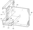
- FIG. 1is a partial isometric view showing an embodiment of a connector plate of the invention in engagement with a first building component
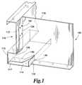
- FIG. 2is a partial isometric view showing the connector plate of FIG. 1 attached to a second building component
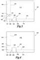
- FIG. 3is an elevational view showing how the connector plate of FIG. 1 can be constructed from a single metal sheet
- FIG. 4is an elevational view showing how another embodiment of the connector plate can be constructed from a single metal sheet
- FIG. 5is an isometric view of the connector plate of FIG. 1;
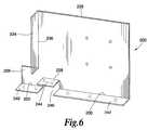
- FIG. 6is an isometric view of the connector plate of FIG. 4;
- FIG. 7 ( a )is a diagrammatical view showing the connector plate of FIG. 4 before engagement with the first building component
- FIG. 7 ( b )is a diagrammatical view showing the connector plate of FIG. 4 in engagement with the first building component
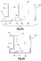
- FIG. 8 ( a )is a diagrammatical view showing the connector plate of FIG. 1 before engagement with the first building component
- FIG. 8 ( b )is a diagrammatical view showing the connector plate of FIG. 1 in engagement with the first building component.
- a connector plate of the inventionfor connecting building components, such as, for example, beams, joists, girders, etc.
- the building componentsmay also comprise components of supporting or supported trusses, such as girder trusses, corner or jack or hip trusses, used, for example, in roof systems.
- One connector plate embodimentmay be used to attach a first building component to a second building component.
- the first building componentmay be any building component having a first web and a first leg extending outwardly from the first web.
- the first legmay also have a lip protruding from the first leg.
- a first building componentmay include, for example, the bottom chord of a girder truss or other supporting truss, or any beam or joist that has a generally L-shaped cross-section that includes a web and a leg, as will be described in more detail herein.
- the second building componentmay be any building component having a cross-section that includes a web and a leg generally extending from the web, and may include the bottom chord of a jack truss or other supported truss, or any beam or joist having such cross-section.
- the characterizations of various components described herein as extending, for example, upwardly or downwardly, or being vertical or horizontalare relative characterizations only based upon the particular position or orientation of a given component for a particular application.
- the first building componentmay comprise a girder truss that has a horizontal bottom chord with a vertical web
- the second building componentmay comprise a jack truss that also has a horizontal bottom chord with a vertical web.
- FIG. 1is a partial isometric view showing an embodiment of a connector plate 100 of the invention in engagement with a first building component 110 .
- the first building component 110has a first web 112 and a first leg 114 that extends generally outwardly from the first web 112 .
- the first building component 110also has a lip 116 that protrudes from the first leg 114 .
- the lip 116is parallel to a lower first web portion 113 .
- the lip 116 and the lower web portion 113define a toe-receiving area, generally designated as 117 .
- the connector plate 100is shown in FIG. 2 attached to a second building component 120 .
- the second building component 120has a second web 122 and a second leg 124 extending generally outwardly from the second web 122 .
- the connector plate 100includes a back plate 118 structured for attachment to the second web 122 of the second building component 120 , as shown in FIG. 2 .
- the back plate 118has an area defining a toe 126 that is sized to be received in the toe-receiving area 117 of the first building component 110 .
- the back plate 118has a middle edge 128 and a bottom edge 130 that is sized to be received on the second leg 124 of the second building component 120 .
- the middle edge 128 and the bottom edgedefine a planar notch 132 sized to receive a portion of the lip 116 therein.
- the connector plate 100may further include a side flange 134 that protrudes from a side 136 of the back plate 118 .
- the side flange 134is structured for attachment to the first web 112 of the first building component 110 .
- the plane of the side flange 134 and the plane of the back plate 118define an attachment angle 138 , which may have, for example, a value of 90° for connecting a girder truss with a jack truss, but may take other values for connecting other building components that are not disposed orthogonally to each other.
- the connector plate 100further comprises a toe flange 140 that protrudes from the toe 126 and is sized to be received on the first leg 114 of the first building component 110 when the toe 126 is inserted into the toe-receiving area 117 , as shown in FIG. 1 .
- the toe flange 140defines a plane that may be orthogonal with the plane of back plate 118 for applications in which the connector plate is used for building components, such as those shown in FIGS. 1 and 2, which have legs 114 , 124 that are orthogonal to the respective webs 112 , 122 .
- the spatial notch 146intersects the back plate 118 at the planar notch 132 , i.e. the planar notch 132 is the trace of the spatial notch 146 on the back plate 118 .
- the term “notch” without any other qualificationis used herein for the spatial notch 146 .
- the middle edge 128 of the back plate 118may be straight or curved.
- the toe flange 140 and the middle flange 144define an angle 147 of 150°. See FIG. 5 .
- the toe 126has generally a first toe edge 148 , a second toe edge 149 and a third toe edge 150 .
- the first toe edge 148may be parallel to the middle edge 128 of the back plate 118 .
- FIGS. 8 ( a ) and 8 ( b )show respectively in schematic profile the connector plate 100 before and after engagement with the first building component 110 .
- the back plate 118may have pre-punched apertures 152 for easy attachment to the second web 122 of the second building component 120 with fasteners 155 , such as, for example, screws and bolts. See FIG. 2 .
- the connector plate 100may also have embossments on the back plate 118 and/or on any of the flanges 134 , 140 , 144 and 142 .
- the connector plate 200has a back plate 228 having a side 236 , a toe 226 , a toe edge 250 , a middle edge 228 and a bottom edge 230 .
- the connector plate 200also has a side flange 234 , a toe flange 240 , a middle flange 244 and a bottom flange 242 .
- the middle flange 244 and the toe flange 240are parallel.
- the middle flange 244 and the bottom flange 242define a notch 246 for receiving a portion of the lip 116 of the first building component 110 .
- FIGS. 7 ( a ) and 7 ( b )show respectively in schematic profile the connector plate 200 before and after engagement with the first building component 110 .
- the connector plate 100may be conveniently and economically constructed from a single metal sheet using conventional metal forming techniques and presses as shown in FIG. 3.
- a triangular cutout 156is removed by cuts along line 154 of the side flange 134 and edge 148 of the toe 126 .
- a cutis made along line 158 to form the planar notch 132 .
- the flanges 136 , 140 , 144 and 142are then bent along the respective edges 134 , 150 , 128 and 130 at desired angles and the notch 146 that provide clearance for the lip 116 is formed.
- FIG. 4illustrates another embodiment of the connector plate 200 that may be fabricated from a single metal sheet.
- a cutis made along edge 254 to separate the toe 226 from the side flange 234 .
- Cuts along lines 260 and 258are made to separate the middle flange 244 from the toe flange 240 and the bottom flange 242 and to form the planar notch 232 .
- the flanges 234 , 240 , 244 and 242are then bent along the respective edges 236 , 250 , 228 and 230 .
- the side flange 134is brought into engagement with the first web 112 for attachment thereto. See FIG. 1 .
- the notch 146allows the installer to temporarily support the connector plate/jack truss system on the first leg 114 of the first building component 110 and adjust the correct location of the two building components before affixing the side flange 134 to the first web 112 of the first building component 110 . This process makes the installation easier and safer, and eliminates the need for an additional person to hold the jack truss against the girder truss in correct placement while the final attachment is made.
- the toe 126 and the toe flange 140transmit bearing load on the first leg 114 from the weight of the jack truss, and fewer fasteners 160 may be needed to attach the side flange 134 to the first web 112 .
- the order of attaching the connector plate to the first and second building componentsmay be reversed.
- the size of the connector platemay be adjusted appropriately based on the application and the transmitted loads. For example, the height of the connector plate may be reduced, and the connector plate may be stiffened by added embossments.
Landscapes
- Engineering & Computer Science (AREA)
- Architecture (AREA)
- Physics & Mathematics (AREA)
- Electromagnetism (AREA)
- Civil Engineering (AREA)
- Structural Engineering (AREA)
- Joining Of Building Structures In Genera (AREA)
Abstract
Description
Claims (37)
Priority Applications (1)
| Application Number | Priority Date | Filing Date | Title |
|---|---|---|---|
| US09/850,311US6427416B1 (en) | 2001-05-07 | 2001-05-07 | Connector plate |
Applications Claiming Priority (1)
| Application Number | Priority Date | Filing Date | Title |
|---|---|---|---|
| US09/850,311US6427416B1 (en) | 2001-05-07 | 2001-05-07 | Connector plate |
Publications (1)
| Publication Number | Publication Date |
|---|---|
| US6427416B1true US6427416B1 (en) | 2002-08-06 |
Family
ID=25307784
Family Applications (1)
| Application Number | Title | Priority Date | Filing Date |
|---|---|---|---|
| US09/850,311Expired - LifetimeUS6427416B1 (en) | 2001-05-07 | 2001-05-07 | Connector plate |
Country Status (1)
| Country | Link |
|---|---|
| US (1) | US6427416B1 (en) |
Cited By (19)
| Publication number | Priority date | Publication date | Assignee | Title |
|---|---|---|---|---|
| US20030024205A1 (en)* | 2001-08-01 | 2003-02-06 | Michael Strickland | Modular joist shoe |
| US6655099B1 (en)* | 1998-09-14 | 2003-12-02 | Spanbilt Pty Ltd | Clip fastening system for walls |
| US6668510B2 (en)* | 2002-01-04 | 2003-12-30 | Mcmanus Ira J. | Deflection clip for stud wall construction |
| US20040074198A1 (en)* | 2001-11-21 | 2004-04-22 | Eluterio Saldana | Connectors, tracks and system for smooth-faced metal framing |
| US20040163356A1 (en)* | 2002-09-05 | 2004-08-26 | John Rice | Framing member having reinforced end |
| US20060096230A1 (en)* | 2004-10-25 | 2006-05-11 | Superior Steel Components, Inc. | Truss and method for making same |
| US20070260345A1 (en)* | 2006-04-14 | 2007-11-08 | Mifsud Vincent D | Component manufacturing system for a prefabricated building panel |
| US20110067343A1 (en)* | 2003-09-05 | 2011-03-24 | John Rice | Framing Member Having Reinforced End |
| US8529178B2 (en) | 2010-02-19 | 2013-09-10 | Nucor Corporation | Weldless building structures |
| US20140130441A1 (en)* | 2011-06-13 | 2014-05-15 | Nippon Steel & Sumitomo Metal Corporation | Connecting fitting, frame provided with same, and building using frame |
| US9004835B2 (en) | 2010-02-19 | 2015-04-14 | Nucor Corporation | Weldless building structures |
| US9650780B2 (en) | 2013-04-29 | 2017-05-16 | Mitek Holdings, Inc. | Hanger bracket |
| US10047513B2 (en)* | 2016-07-28 | 2018-08-14 | Jing-Xin Solar Ltd. | Beam frame assembly having joint device |
| US10100516B2 (en)* | 2016-10-05 | 2018-10-16 | Fortress Iron, Lp | Deck framing system |
| US10788066B2 (en) | 2016-05-02 | 2020-09-29 | Nucor Corporation | Double threaded standoff fastener |
| US11028580B2 (en) | 2018-05-25 | 2021-06-08 | Fortress Iron, Lp | Deck frame with integral attachment tabs |
| USD959250S1 (en) | 2020-07-22 | 2022-08-02 | Clarkwestern Dietrich Building Systems Llc | Slide clip |
| USD959251S1 (en) | 2020-07-22 | 2022-08-02 | Clarkwestern Dietrich Building Systems Llc | Slide clip |
| US11692340B2 (en) | 2020-07-22 | 2023-07-04 | Clarkwestern Dietrich Building Systems Llc | Slide clip |
Citations (73)
| Publication number | Priority date | Publication date | Assignee | Title |
|---|---|---|---|---|
| DE238822C (en) | ||||
| US522652A (en) | 1894-07-10 | Thomas h | ||
| US625427A (en)* | 1899-05-23 | Wrought-metal joist-hanger | ||
| US813253A (en) | 1905-06-15 | 1906-02-20 | John H Sullivan | Mold. |
| US1156833A (en) | 1915-03-03 | 1915-10-12 | Alfred M Bonhard | Bed. |
| US1174097A (en) | 1914-04-06 | 1916-03-07 | John Robert Spear | Ground-strip and frame fastener. |
| GB185694A (en) | 1921-12-30 | 1922-09-14 | Baden Robert Rowell | Improved joint for floor joists and like weight supporting members |
| US1475078A (en) | 1921-11-19 | 1923-11-20 | Guy A Messacar | Ladder-step bracket |
| US1585897A (en) | 1922-12-27 | 1926-05-25 | C D Pruden Corp | Roof construction |
| US1765107A (en) | 1928-02-13 | 1930-06-17 | Evans Auto Loading Co Inc | Tie-bar hanger |
| US1879459A (en) | 1930-02-20 | 1932-09-27 | Stanley Works | Anchor plate |
| US2413362A (en) | 1944-01-27 | 1946-12-31 | Maxwell & Hitchcock | Metallic clip for connecting and reinforcing joints in wood structures |
| US2519628A (en) | 1949-02-14 | 1950-08-22 | Worldsbest Ind Inc | Curtain stretcher corner structure |
| US3184800A (en) | 1961-10-23 | 1965-05-25 | Lynn H Ewing | Rafter support |
| US3216160A (en) | 1963-04-11 | 1965-11-09 | Harold A Best | Precast concrete step |
| FR1423034A (en) | 1964-11-18 | 1966-01-03 | Removable assembly of cross-shaped profiled elements allowing the construction without perforation of frames intended for all uses | |
| US3229333A (en) | 1962-10-15 | 1966-01-18 | Albert J Hillesheim | Building frame bracket |
| US3425720A (en) | 1966-07-25 | 1969-02-04 | Victor L Spane | Rafter and post structure connection |
| US3751870A (en) | 1971-02-05 | 1973-08-14 | Elkhart Wlding & Boiler Works | Frame structure system |
| US3798865A (en)* | 1972-03-17 | 1974-03-26 | Integrated Ceilings Inc | Grid support structure and clip means therefor |
| US3902298A (en) | 1973-12-20 | 1975-09-02 | United States Steel Corp | Saddle clip for mounting and reinforceably supporting C-shape metal beams |
| US3907445A (en) | 1975-01-06 | 1975-09-23 | United States Gypsum Co | Self-aligning joist hanger for structural steel framing |
| US3918232A (en) | 1972-01-31 | 1975-11-11 | Universal Modular Structures I | L-connector for grooved structural elements |
| US3945741A (en) | 1975-01-06 | 1976-03-23 | United States Gypsum Company | Self-aligning hanger attachment bracket for structural steel joists |
| US4144683A (en) | 1977-07-05 | 1979-03-20 | Spiral-Craft | Bracket assembly |
| US4335555A (en) | 1980-03-10 | 1982-06-22 | Robert D. Southerland | Rafter assembly and fixtures |
| US4353664A (en) | 1980-07-24 | 1982-10-12 | Simpson Manufacturing Co., Inc. | Free gusset metal ledger hanger |
| US4433524A (en) | 1981-06-19 | 1984-02-28 | Nostam, Inc. | Method and apparatus for slip-connector structural joint |
| US4464074A (en)* | 1981-12-28 | 1984-08-07 | United States Gypsum Company | Connector and web stiffener |
| US4498801A (en) | 1981-01-09 | 1985-02-12 | Simpson Strong-Tie Company, Inc. | Ridge rafter connector |
| US4513554A (en) | 1982-12-27 | 1985-04-30 | Lawrence Brothers, Inc. | Barn door framing system |
| US4517776A (en)* | 1983-03-10 | 1985-05-21 | The Dow Chemical Company | Roof insulation retention |
| US4525972A (en) | 1982-09-24 | 1985-07-02 | Gang Nail Systems, Inc. | Truss assembly and bracing clip and attachment member for use with trusses |
| US4570400A (en)* | 1983-12-12 | 1986-02-18 | United States Gypsum Company | Curtain wall stud slide clip |
| US4593509A (en) | 1982-10-07 | 1986-06-10 | Linton Systems Limited | Building structure |
| US4688358A (en) | 1983-05-23 | 1987-08-25 | Madray Herbert R | Construction system |
| US4817359A (en) | 1988-02-01 | 1989-04-04 | Simpson Strong-Tie Company, Inc. | Multiple wood truss connection |
| US4893961A (en) | 1989-06-05 | 1990-01-16 | Trus Joist Corporation | Joist hanger |
| US4920713A (en) | 1989-10-18 | 1990-05-01 | V. Kann Rasmussen Industri A/S | Prefabricated window for installation in an inclined roof |
| US4932173A (en) | 1988-07-21 | 1990-06-12 | Simpson Strong-Tie Company, Inc. | Truss clip |
| US5042217A (en) | 1990-11-08 | 1991-08-27 | Simpson Strong-Tie Company, Inc. | Light wood truss connection |
| US5062733A (en) | 1989-05-03 | 1991-11-05 | Bulldog Beratungs-Und Vertriebs-Gmbh | Joining element for beams |
| US5109646A (en) | 1991-05-14 | 1992-05-05 | Simpson Strong-Tie Company, Inc. | Bearing connection |
| US5186571A (en) | 1991-01-07 | 1993-02-16 | Desco Corporation | Fence rail bracket |
| US5220766A (en) | 1991-12-30 | 1993-06-22 | Southeastern Metals Mfg. Co., Inc. | Skewed beam hanger |
| US5236273A (en) | 1991-12-17 | 1993-08-17 | Simpson Strong-Tie Company, Inc. | Rafter-to-corner plate connection |
| US5253465A (en) | 1992-02-26 | 1993-10-19 | Simpson Strong-Tie Company, Inc. | Multiple framing member connection |
| US5341619A (en) | 1993-04-09 | 1994-08-30 | Simpson Strong-Tie Company, Inc. | Truss girder hanger connection |
| US5380115A (en) | 1993-10-14 | 1995-01-10 | Simpson Strong-Tie Co., Inc. | Hip corner plate connection |
| US5380116A (en) | 1993-10-14 | 1995-01-10 | Simpson Strong-Tie Company, Inc. | Hip ridge connection |
| US5419649A (en) | 1994-02-10 | 1995-05-30 | Simpson Strong-Tie Co., Inc. | Intermediate rail to post connection |
| US5457927A (en) | 1993-07-15 | 1995-10-17 | Mitek Holdings, Inc. | Truss |
| US5551792A (en) | 1995-04-28 | 1996-09-03 | Armstrong World Industries, Inc. | Connector |
| US5598680A (en) | 1993-12-13 | 1997-02-04 | Wilhelmi; Juergen | Joining element for joining wooden components |
| US5617694A (en) | 1994-04-27 | 1997-04-08 | Kabushiki Kaisha Kenchiku Shiryo Kenkyusha | Beam or girder joint element |
| US5625995A (en) | 1994-07-15 | 1997-05-06 | Consolidated Systems, Inc. | Method and flooring system with aligning bracket for mutually securing a header, a joist and a base |
| US5657596A (en) | 1994-05-25 | 1997-08-19 | Powers, Iii; John | Fabricated building with metal purlins |
| US5664392A (en) | 1996-04-08 | 1997-09-09 | Mucha; Brian A. | Deflection clip |
| US5720571A (en) | 1994-12-22 | 1998-02-24 | Super Stud Building Products, Inc. | Deflection slide clip |
| US5806265A (en) | 1996-01-25 | 1998-09-15 | Sluiter; Scott E. | Metal truss joining gusset |
| US5836131A (en) | 1994-12-22 | 1998-11-17 | Super Stud Building Products | Joist hanger |
| US5857306A (en)* | 1997-04-02 | 1999-01-12 | Mitek Holdings, Inc. | Truss-to-truss assemblies and connectors therefor |
| US5906080A (en) | 1997-05-15 | 1999-05-25 | Digirolamo; Edward R. | Bracket for interconnecting a building stud to primary structural components |
| US5924259A (en)* | 1998-02-17 | 1999-07-20 | Marousek; Robert Y. | Corner piece for siding retainers |
| EP0950817A2 (en) | 1998-04-14 | 1999-10-20 | Fischerwerke Arthur Fischer GmbH & Co. KG | Angle connecting element |
| US5983589A (en) | 1997-03-21 | 1999-11-16 | Dietrich Industries, Inc. | Truss pitch break connector plate |
| US6047507A (en)* | 1998-06-19 | 2000-04-11 | Certainteed Corporation | Lineal corner block |
| US6050041A (en)* | 1998-07-24 | 2000-04-18 | Associated Materials, Inc. | Splicing member for siding panels |
| US6125594A (en) | 1999-03-29 | 2000-10-03 | Hudson; Mark | Roof angle attachment device |
| US6199929B1 (en) | 2000-01-25 | 2001-03-13 | Ronald D. Hansch | Sideboard bracket |
| US6213679B1 (en)* | 1999-10-08 | 2001-04-10 | Super Stud Building Products, Inc. | Deflection slide clip |
| US6298630B1 (en) | 2000-05-18 | 2001-10-09 | Verost Russell L. | Wall plate for attaching beams to masonry walls |
| US6301854B1 (en) | 1998-11-25 | 2001-10-16 | Dietrich Industries, Inc. | Floor joist and support system therefor |
- 2001
- 2001-05-07USUS09/850,311patent/US6427416B1/ennot_activeExpired - Lifetime
Patent Citations (74)
| Publication number | Priority date | Publication date | Assignee | Title |
|---|---|---|---|---|
| DE238822C (en) | ||||
| US522652A (en) | 1894-07-10 | Thomas h | ||
| US625427A (en)* | 1899-05-23 | Wrought-metal joist-hanger | ||
| US813253A (en) | 1905-06-15 | 1906-02-20 | John H Sullivan | Mold. |
| US1174097A (en) | 1914-04-06 | 1916-03-07 | John Robert Spear | Ground-strip and frame fastener. |
| US1156833A (en) | 1915-03-03 | 1915-10-12 | Alfred M Bonhard | Bed. |
| US1475078A (en) | 1921-11-19 | 1923-11-20 | Guy A Messacar | Ladder-step bracket |
| GB185694A (en) | 1921-12-30 | 1922-09-14 | Baden Robert Rowell | Improved joint for floor joists and like weight supporting members |
| US1585897A (en) | 1922-12-27 | 1926-05-25 | C D Pruden Corp | Roof construction |
| US1765107A (en) | 1928-02-13 | 1930-06-17 | Evans Auto Loading Co Inc | Tie-bar hanger |
| US1879459A (en) | 1930-02-20 | 1932-09-27 | Stanley Works | Anchor plate |
| US2413362A (en) | 1944-01-27 | 1946-12-31 | Maxwell & Hitchcock | Metallic clip for connecting and reinforcing joints in wood structures |
| US2519628A (en) | 1949-02-14 | 1950-08-22 | Worldsbest Ind Inc | Curtain stretcher corner structure |
| US3184800A (en) | 1961-10-23 | 1965-05-25 | Lynn H Ewing | Rafter support |
| US3229333A (en) | 1962-10-15 | 1966-01-18 | Albert J Hillesheim | Building frame bracket |
| US3216160A (en) | 1963-04-11 | 1965-11-09 | Harold A Best | Precast concrete step |
| FR1423034A (en) | 1964-11-18 | 1966-01-03 | Removable assembly of cross-shaped profiled elements allowing the construction without perforation of frames intended for all uses | |
| US3425720A (en) | 1966-07-25 | 1969-02-04 | Victor L Spane | Rafter and post structure connection |
| US3751870A (en) | 1971-02-05 | 1973-08-14 | Elkhart Wlding & Boiler Works | Frame structure system |
| US3918232A (en) | 1972-01-31 | 1975-11-11 | Universal Modular Structures I | L-connector for grooved structural elements |
| US3798865A (en)* | 1972-03-17 | 1974-03-26 | Integrated Ceilings Inc | Grid support structure and clip means therefor |
| US3902298A (en) | 1973-12-20 | 1975-09-02 | United States Steel Corp | Saddle clip for mounting and reinforceably supporting C-shape metal beams |
| US3907445A (en) | 1975-01-06 | 1975-09-23 | United States Gypsum Co | Self-aligning joist hanger for structural steel framing |
| US3945741A (en) | 1975-01-06 | 1976-03-23 | United States Gypsum Company | Self-aligning hanger attachment bracket for structural steel joists |
| US4144683A (en) | 1977-07-05 | 1979-03-20 | Spiral-Craft | Bracket assembly |
| US4335555A (en) | 1980-03-10 | 1982-06-22 | Robert D. Southerland | Rafter assembly and fixtures |
| US4353664A (en) | 1980-07-24 | 1982-10-12 | Simpson Manufacturing Co., Inc. | Free gusset metal ledger hanger |
| US4498801A (en) | 1981-01-09 | 1985-02-12 | Simpson Strong-Tie Company, Inc. | Ridge rafter connector |
| US4433524A (en) | 1981-06-19 | 1984-02-28 | Nostam, Inc. | Method and apparatus for slip-connector structural joint |
| US4464074A (en)* | 1981-12-28 | 1984-08-07 | United States Gypsum Company | Connector and web stiffener |
| US4525972A (en) | 1982-09-24 | 1985-07-02 | Gang Nail Systems, Inc. | Truss assembly and bracing clip and attachment member for use with trusses |
| US4593509A (en) | 1982-10-07 | 1986-06-10 | Linton Systems Limited | Building structure |
| US4513554A (en) | 1982-12-27 | 1985-04-30 | Lawrence Brothers, Inc. | Barn door framing system |
| US4517776A (en)* | 1983-03-10 | 1985-05-21 | The Dow Chemical Company | Roof insulation retention |
| US4688358A (en) | 1983-05-23 | 1987-08-25 | Madray Herbert R | Construction system |
| US4570400A (en)* | 1983-12-12 | 1986-02-18 | United States Gypsum Company | Curtain wall stud slide clip |
| US4817359A (en) | 1988-02-01 | 1989-04-04 | Simpson Strong-Tie Company, Inc. | Multiple wood truss connection |
| US4932173A (en) | 1988-07-21 | 1990-06-12 | Simpson Strong-Tie Company, Inc. | Truss clip |
| US5062733A (en) | 1989-05-03 | 1991-11-05 | Bulldog Beratungs-Und Vertriebs-Gmbh | Joining element for beams |
| US4893961A (en) | 1989-06-05 | 1990-01-16 | Trus Joist Corporation | Joist hanger |
| US4920713A (en) | 1989-10-18 | 1990-05-01 | V. Kann Rasmussen Industri A/S | Prefabricated window for installation in an inclined roof |
| US5042217A (en) | 1990-11-08 | 1991-08-27 | Simpson Strong-Tie Company, Inc. | Light wood truss connection |
| US5186571A (en) | 1991-01-07 | 1993-02-16 | Desco Corporation | Fence rail bracket |
| US5109646A (en) | 1991-05-14 | 1992-05-05 | Simpson Strong-Tie Company, Inc. | Bearing connection |
| US5236273A (en) | 1991-12-17 | 1993-08-17 | Simpson Strong-Tie Company, Inc. | Rafter-to-corner plate connection |
| US5220766A (en) | 1991-12-30 | 1993-06-22 | Southeastern Metals Mfg. Co., Inc. | Skewed beam hanger |
| US5253465A (en) | 1992-02-26 | 1993-10-19 | Simpson Strong-Tie Company, Inc. | Multiple framing member connection |
| US5341619A (en) | 1993-04-09 | 1994-08-30 | Simpson Strong-Tie Company, Inc. | Truss girder hanger connection |
| US5457927A (en) | 1993-07-15 | 1995-10-17 | Mitek Holdings, Inc. | Truss |
| US5380115A (en) | 1993-10-14 | 1995-01-10 | Simpson Strong-Tie Co., Inc. | Hip corner plate connection |
| US5380116A (en) | 1993-10-14 | 1995-01-10 | Simpson Strong-Tie Company, Inc. | Hip ridge connection |
| US5598680A (en) | 1993-12-13 | 1997-02-04 | Wilhelmi; Juergen | Joining element for joining wooden components |
| US5419649A (en) | 1994-02-10 | 1995-05-30 | Simpson Strong-Tie Co., Inc. | Intermediate rail to post connection |
| US5617694A (en) | 1994-04-27 | 1997-04-08 | Kabushiki Kaisha Kenchiku Shiryo Kenkyusha | Beam or girder joint element |
| US5657596A (en) | 1994-05-25 | 1997-08-19 | Powers, Iii; John | Fabricated building with metal purlins |
| US5625995A (en) | 1994-07-15 | 1997-05-06 | Consolidated Systems, Inc. | Method and flooring system with aligning bracket for mutually securing a header, a joist and a base |
| US5836131A (en) | 1994-12-22 | 1998-11-17 | Super Stud Building Products | Joist hanger |
| US5720571A (en) | 1994-12-22 | 1998-02-24 | Super Stud Building Products, Inc. | Deflection slide clip |
| US5551792A (en) | 1995-04-28 | 1996-09-03 | Armstrong World Industries, Inc. | Connector |
| US6076325A (en) | 1996-01-25 | 2000-06-20 | Sluiter; Scott E. | Metal truss joining gusset |
| US5806265A (en) | 1996-01-25 | 1998-09-15 | Sluiter; Scott E. | Metal truss joining gusset |
| US5664392A (en) | 1996-04-08 | 1997-09-09 | Mucha; Brian A. | Deflection clip |
| US5983589A (en) | 1997-03-21 | 1999-11-16 | Dietrich Industries, Inc. | Truss pitch break connector plate |
| US5857306A (en)* | 1997-04-02 | 1999-01-12 | Mitek Holdings, Inc. | Truss-to-truss assemblies and connectors therefor |
| US5906080A (en) | 1997-05-15 | 1999-05-25 | Digirolamo; Edward R. | Bracket for interconnecting a building stud to primary structural components |
| US5924259A (en)* | 1998-02-17 | 1999-07-20 | Marousek; Robert Y. | Corner piece for siding retainers |
| EP0950817A2 (en) | 1998-04-14 | 1999-10-20 | Fischerwerke Arthur Fischer GmbH & Co. KG | Angle connecting element |
| US6047507A (en)* | 1998-06-19 | 2000-04-11 | Certainteed Corporation | Lineal corner block |
| US6050041A (en)* | 1998-07-24 | 2000-04-18 | Associated Materials, Inc. | Splicing member for siding panels |
| US6301854B1 (en) | 1998-11-25 | 2001-10-16 | Dietrich Industries, Inc. | Floor joist and support system therefor |
| US6125594A (en) | 1999-03-29 | 2000-10-03 | Hudson; Mark | Roof angle attachment device |
| US6213679B1 (en)* | 1999-10-08 | 2001-04-10 | Super Stud Building Products, Inc. | Deflection slide clip |
| US6199929B1 (en) | 2000-01-25 | 2001-03-13 | Ronald D. Hansch | Sideboard bracket |
| US6298630B1 (en) | 2000-05-18 | 2001-10-09 | Verost Russell L. | Wall plate for attaching beams to masonry walls |
Cited By (40)
| Publication number | Priority date | Publication date | Assignee | Title |
|---|---|---|---|---|
| US6655099B1 (en)* | 1998-09-14 | 2003-12-02 | Spanbilt Pty Ltd | Clip fastening system for walls |
| US20030024205A1 (en)* | 2001-08-01 | 2003-02-06 | Michael Strickland | Modular joist shoe |
| US20040074198A1 (en)* | 2001-11-21 | 2004-04-22 | Eluterio Saldana | Connectors, tracks and system for smooth-faced metal framing |
| US7216465B2 (en)* | 2001-11-21 | 2007-05-15 | Eluterio Saldana | Connectors, tracks and system for smooth-faced metal framing |
| US6668510B2 (en)* | 2002-01-04 | 2003-12-30 | Mcmanus Ira J. | Deflection clip for stud wall construction |
| US20040163356A1 (en)* | 2002-09-05 | 2004-08-26 | John Rice | Framing member having reinforced end |
| US20110067343A1 (en)* | 2003-09-05 | 2011-03-24 | John Rice | Framing Member Having Reinforced End |
| US9777479B2 (en)* | 2003-09-05 | 2017-10-03 | Bailey Metal Products Limited | Framing member having reinforced end |
| US20060096230A1 (en)* | 2004-10-25 | 2006-05-11 | Superior Steel Components, Inc. | Truss and method for making same |
| US20070261318A1 (en)* | 2006-04-14 | 2007-11-15 | Mifsud Vincent D | Kit for manufacturing an enclosure from prefabricated panels |
| US7894920B2 (en) | 2006-04-14 | 2011-02-22 | Genesis TP, Inc. | Information technology process for prefabricated building panel assembly |
| US20070264107A1 (en)* | 2006-04-14 | 2007-11-15 | Mifsud Vincent D | Material transport system for building panel assembly |
| US20070265724A1 (en)* | 2006-04-14 | 2007-11-15 | Mifsud Vincent D | Information technology process for prefabricated building panel assembly |
| US20070264108A1 (en)* | 2006-04-14 | 2007-11-15 | Mifsud Vincent D | Bi-directional roller table |
| US20070271870A1 (en)* | 2006-04-14 | 2007-11-29 | Mifsud Vincent D | Manufacturing method for a prefabricated building panel |
| US7835810B2 (en) | 2006-04-14 | 2010-11-16 | Genesistp, Inc. | Tools and methods for designing a structure using prefabricated panels |
| US20070260345A1 (en)* | 2006-04-14 | 2007-11-08 | Mifsud Vincent D | Component manufacturing system for a prefabricated building panel |
| US20070262040A1 (en)* | 2006-04-14 | 2007-11-15 | Mifsud Vincent D | Overhead gantry for use in building panel construction |
| US20070256392A1 (en)* | 2006-04-14 | 2007-11-08 | Mifsud Vincent D | Automatic pinning process for building panel assembly |
| US8636456B2 (en) | 2010-02-19 | 2014-01-28 | Nucor Corporation | Weldless building structures |
| US8529178B2 (en) | 2010-02-19 | 2013-09-10 | Nucor Corporation | Weldless building structures |
| US9267527B2 (en) | 2010-02-19 | 2016-02-23 | Nucor Corporation | Weldless building structures |
| US9004835B2 (en) | 2010-02-19 | 2015-04-14 | Nucor Corporation | Weldless building structures |
| US20140130441A1 (en)* | 2011-06-13 | 2014-05-15 | Nippon Steel & Sumitomo Metal Corporation | Connecting fitting, frame provided with same, and building using frame |
| US8973333B2 (en)* | 2011-06-13 | 2015-03-10 | Sekisui House, Ltd. | Connecting fitting, frame provided with same, and building using frame |
| US10214897B2 (en) | 2013-04-29 | 2019-02-26 | Mitek Holdings, Inc. | Hanger bracket |
| US9650780B2 (en) | 2013-04-29 | 2017-05-16 | Mitek Holdings, Inc. | Hanger bracket |
| US10788066B2 (en) | 2016-05-02 | 2020-09-29 | Nucor Corporation | Double threaded standoff fastener |
| US11815123B2 (en) | 2016-05-02 | 2023-11-14 | Nucor Corporation | Double threaded standoff fastener |
| US10047513B2 (en)* | 2016-07-28 | 2018-08-14 | Jing-Xin Solar Ltd. | Beam frame assembly having joint device |
| US11066830B2 (en) | 2016-10-05 | 2021-07-20 | Fortress Iron, Lp | Deck framing system |
| US10550570B2 (en) | 2016-10-05 | 2020-02-04 | Fortress Iron, Lp | Deck framing system |
| US11598090B2 (en) | 2016-10-05 | 2023-03-07 | Fortress Iron, Lp | Deck framing system |
| US10100516B2 (en)* | 2016-10-05 | 2018-10-16 | Fortress Iron, Lp | Deck framing system |
| US12421719B2 (en) | 2016-10-05 | 2025-09-23 | Fortress Iron, Lp | Deck framing system |
| US11028580B2 (en) | 2018-05-25 | 2021-06-08 | Fortress Iron, Lp | Deck frame with integral attachment tabs |
| USD959250S1 (en) | 2020-07-22 | 2022-08-02 | Clarkwestern Dietrich Building Systems Llc | Slide clip |
| USD959251S1 (en) | 2020-07-22 | 2022-08-02 | Clarkwestern Dietrich Building Systems Llc | Slide clip |
| US11692340B2 (en) | 2020-07-22 | 2023-07-04 | Clarkwestern Dietrich Building Systems Llc | Slide clip |
| US11905700B2 (en) | 2020-07-22 | 2024-02-20 | Clarkwestern Dietrich Building Systems Llc | Slide clip |
Similar Documents
| Publication | Publication Date | Title |
|---|---|---|
| US6427416B1 (en) | Connector plate | |
| CA2719864C (en) | Four-way radial connector | |
| US5341619A (en) | Truss girder hanger connection | |
| US4561230A (en) | Truss assembly and truss hanger and connector hanger for use with trusses | |
| US5664388A (en) | Structural shear resisting member and method employed therein | |
| US5253465A (en) | Multiple framing member connection | |
| US4423977A (en) | Single element slope and skew hanger | |
| US4897979A (en) | Multiple wood truss connection | |
| US4455805A (en) | Truss assembly and truss hanger for use with trusses | |
| US5042217A (en) | Light wood truss connection | |
| AU2010241246B2 (en) | Building frame | |
| CA2227540C (en) | Framing system for wood frame buildings | |
| US4890436A (en) | Multiple wood truss connection | |
| EP1760212B1 (en) | Skewed girder tie | |
| EP1760213A2 (en) | Right-angle girder tie | |
| NZ521230A (en) | Truss brace with retainers at opposite ends and truss structure made therewith | |
| US6513298B2 (en) | Web connector | |
| CA2293322A1 (en) | A framing system for buildings | |
| JP7553605B2 (en) | DRYWORK CONNECTORS, DRYWORK ARRANGEMENTS, KITS AND METHODS FOR CONSTRUCTING DRYWORK CEILINGS - Patent application | |
| AU746401B2 (en) | A framing system for buildings | |
| AU602119B2 (en) | Structural assemblies | |
| WO1998057001A1 (en) | A framing system for buildings | |
| CA1194673A (en) | Truss assembly and truss hanger and connector hanger for use with trusses | |
| GB2315502A (en) | Improvements in or relating to roofing | |
| HK1101782A (en) | Skewed girder tie |
Legal Events
| Date | Code | Title | Description |
|---|---|---|---|
| AS | Assignment | Owner name:DIETRICH INDUSTRIES, INC., PENNSYLVANIA Free format text:ASSIGNMENT OF ASSIGNORS INTEREST;ASSIGNOR:RASSEL, DOUGLAS A.;REEL/FRAME:011800/0470 Effective date:20010501 | |
| AS | Assignment | Owner name:AEGIS METAL FRAMING LLC, MISSOURI Free format text:ASSIGNMENT OF ASSIGNORS INTEREST;ASSIGNOR:DIETRICH INDUSTRIES, INC.;REEL/FRAME:012676/0073 Effective date:20020201 | |
| STCF | Information on status: patent grant | Free format text:PATENTED CASE | |
| CC | Certificate of correction | ||
| FPAY | Fee payment | Year of fee payment:4 | |
| FPAY | Fee payment | Year of fee payment:8 | |
| AS | Assignment | Owner name:MITEK INDUSTRIES, INC.,MISSOURI Free format text:MERGER;ASSIGNOR:AEGIS METAL FRAMING, LLC;REEL/FRAME:024023/0118 Effective date:20090101 | |
| AS | Assignment | Owner name:MITEK INDUSTRIES, INC.,MISSOURI Free format text:MERGER;ASSIGNOR:AEGIS METAL FRAMING, LLC;REEL/FRAME:024023/0180 Effective date:20090101 Owner name:MITEK HOLDINGS, INC.,DELAWARE Free format text:ASSIGNMENT OF ASSIGNORS INTEREST;ASSIGNOR:MITEK INDUSTRIES, INC.;REEL/FRAME:024023/0184 Effective date:20100226 | |
| FPAY | Fee payment | Year of fee payment:12 |