US6426983B1 - Method and apparatus of using a bank of filters for excision of narrow band interference signal from CDMA signal - Google Patents
Method and apparatus of using a bank of filters for excision of narrow band interference signal from CDMA signalDownload PDFInfo
- Publication number
- US6426983B1 US6426983B1US09/152,645US15264598AUS6426983B1US 6426983 B1US6426983 B1US 6426983B1US 15264598 AUS15264598 AUS 15264598AUS 6426983 B1US6426983 B1US 6426983B1
- Authority
- US
- United States
- Prior art keywords
- signals
- signal
- filters
- sub band
- output
- Prior art date
- Legal status (The legal status is an assumption and is not a legal conclusion. Google has not performed a legal analysis and makes no representation as to the accuracy of the status listed.)
- Expired - Lifetime
Links
- 238000000034methodMethods0.000titleclaimsdescription34
- 230000015572biosynthetic processEffects0.000claimsabstractdescription38
- 238000003786synthesis reactionMethods0.000claimsabstractdescription38
- 239000011159matrix materialSubstances0.000claimsabstractdescription15
- 238000004458analytical methodMethods0.000claimsdescription52
- 238000001514detection methodMethods0.000claimsdescription44
- 230000002452interceptive effectEffects0.000claimsdescription29
- 230000008569processEffects0.000claimsdescription27
- 230000004044responseEffects0.000claimsdescription26
- 238000012546transferMethods0.000claimsdescription18
- 238000001228spectrumMethods0.000claimsdescription17
- 238000001914filtrationMethods0.000claimsdescription9
- 230000008878couplingEffects0.000claimsdescription5
- 238000010168coupling processMethods0.000claimsdescription5
- 238000005859coupling reactionMethods0.000claimsdescription5
- 230000002238attenuated effectEffects0.000claimsdescription4
- 230000002087whitening effectEffects0.000claimsdescription2
- 230000035945sensitivityEffects0.000claims2
- 230000008030eliminationEffects0.000claims1
- 238000003379elimination reactionMethods0.000claims1
- 230000009467reductionEffects0.000claims1
- 238000004891communicationMethods0.000abstractdescription12
- 230000003044adaptive effectEffects0.000abstractdescription11
- 239000002131composite materialSubstances0.000abstractdescription3
- 238000010586diagramMethods0.000description14
- 238000012545processingMethods0.000description8
- 230000006978adaptationEffects0.000description5
- 238000012937correctionMethods0.000description4
- 230000004048modificationEffects0.000description4
- 238000012986modificationMethods0.000description4
- 238000004364calculation methodMethods0.000description3
- 230000005540biological transmissionEffects0.000description2
- 239000000969carrierSubstances0.000description2
- 238000006243chemical reactionMethods0.000description2
- 238000011144upstream manufacturingMethods0.000description2
- 230000002411adverseEffects0.000description1
- 230000008901benefitEffects0.000description1
- 230000008859changeEffects0.000description1
- 239000004020conductorSubstances0.000description1
- 238000010276constructionMethods0.000description1
- 230000006735deficitEffects0.000description1
- 230000001934delayEffects0.000description1
- 230000000694effectsEffects0.000description1
- 238000005516engineering processMethods0.000description1
- 238000011156evaluationMethods0.000description1
- 239000000835fiberSubstances0.000description1
- 230000036039immunityEffects0.000description1
- RGCLLPNLLBQHPF-HJWRWDBZSA-NphosphamidonChemical compoundCCN(CC)C(=O)C(\Cl)=C(/C)OP(=O)(OC)OCRGCLLPNLLBQHPF-HJWRWDBZSA-N0.000description1
- 238000011084recoveryMethods0.000description1
- 230000007480spreadingEffects0.000description1
- 210000003813thumbAnatomy0.000description1
Images


Classifications
- H—ELECTRICITY
- H04—ELECTRIC COMMUNICATION TECHNIQUE
- H04B—TRANSMISSION
- H04B1/00—Details of transmission systems, not covered by a single one of groups H04B3/00 - H04B13/00; Details of transmission systems not characterised by the medium used for transmission
- H04B1/69—Spread spectrum techniques
- H04B1/707—Spread spectrum techniques using direct sequence modulation
- H04B1/7097—Interference-related aspects
- H04B1/71—Interference-related aspects the interference being narrowband interference
- H04B1/7102—Interference-related aspects the interference being narrowband interference with transform to frequency domain
- H—ELECTRICITY
- H04—ELECTRIC COMMUNICATION TECHNIQUE
- H04B—TRANSMISSION
- H04B1/00—Details of transmission systems, not covered by a single one of groups H04B3/00 - H04B13/00; Details of transmission systems not characterised by the medium used for transmission
- H04B1/69—Spread spectrum techniques
- H04B1/707—Spread spectrum techniques using direct sequence modulation
- H04B1/709—Correlator structure
Definitions
- the inventionis useful in code division multiple access digital data transmission systems and other digital data transmission systems using carriers to eliminate or substantially reduce narrow band noise power.
- This frequency excision capabilityis highly desirable in, for example, the new digital data delivery systems for delivering high bandwidth telephone service, video on demand and high speed internet access to subscribers on cable TV systems via the hybrid fiber-coax cable plant. Frequency excision also allows transmitted power levels to be reduced.
- ADFadaptive digital filtering
- ADFprovides a wide variety of estimation algorithms with varying response times, but the algorithms that were study by Young and his co-author were limited in the number of interferers that can be rejected by the number of delays (poles and zeroes).
- DFTdiscrete Fourier transform
- DFT algorithmsdiffer from SAW filter based techniques in that digital technology is used which yields greater freedom in designing the interference removal algorithm and easily provide high dynamic range.
- the number of interfering signals that can be removedis related to the length of the DFT and may easily extend into the hundreds for a 1024 point DFT and notch depths on the order of 60 dB can be achieved.
- DFT excision algorithmsare software based. Because of this fact, they are too slow for many applications where data rates and traffic volume are very high such as in digital service delivery over cable modem based systems.
- Kohriproposed a narrowband interference suppressor using a bank polyphase FIR decimating (dividing) filters, a limiter and a bank of combining or interpolator filters at the front end of a CDMA receiver.
- the transfer function of the filter bankwas a series of individual, non-overlapping transfer functions, and no error predicting equalizer was taught to cancel colored noise. Likewise, perfect reconstruction filters were not taught.
- the limiterwas taught as a nonlinear amplifier.
- a narrow band interference excision circuit for use in any broadband digital data communication systems such as CDMA or TDMA systemsis disclosed herein.
- Broadbandas the term is used herein means any transmitted signal with a broad bandwidth such as code division multiplexed signals or TDMA signals where the symbol rate is high. Basically, TDMA signals with a symbol rate approaching or exceeding the chip rate of CDMA systems has as high a bandwidth or higher for the transmitted signals as CDMA signals.
- transmitted signalor “transmitted signals” in the claims is intended to include both TDMA and CDMA signals as well as any other broad bandwidth transmitted signal that could have narrow bandwidth interfering signals therein.
- the excision circuitis comprised of a bank of analysis filters and a bank of synthesis filters separated by an excision circuit. Together, these two collections of filters implement a set of perfect reconstruction filters.
- the analysis filtersfunction to divide the input signal into a plurality of narrow subbands and have overlapping frequency responses so as to eliminate blind spots in analyzing the entire broadband spectrum.
- Each narrow subband signalis examined continuously or iteratively to determine if narrowband interference exists in that bin at the time of each iteration. This is done preferably by computing the power of the signals in each subband. If the power in a subband exceeds a threshold, preferably adaptable, then the entire subband is eliminated. This threshold is set so as to detect most instances of narrowband interference.
- Alternative embodimentstake the average power in every bin or do an FFT of every bin to look for noise peaks or compute the variance of the signal amplitude or power at every frequency from the mean and, if any peak exceeds some threshold delta value (which may be programmable or adaptive in some embodiments), the bin is erased or a notch filter is programmed to take out the peak. Since this process is carried out iteratively on every bin, interfering signals which have their bandwidth increase and decrease cause as many bins as they infect at any particular iteration to be erased and to continue to be erased on subsequent iterations until the interference level drops below the threshold delta value for those bins. In other words, the process is an ongoing evaluation of every bin, and every bin that is infected with an interfering signal on any particular iteration will be erased or suppressed.
- some threshold delta valuewhich may be programmable or adaptive in some embodiments
- a bank of polyphase synthesis filtersreassembles the composite signal.
- Polyphase filters and the Noble Identityare used to enable lowering the complexity of the filter structure by using decimators to lower the sample rate entering each filter and performing interpolation after the synthesis bank to raise the sample rate back up the sample rate going into the decimators.
- polyphase filtersneed not be used and more complex analysis and synthesis filter banks are used and more complex detection and cancellation circuits are used so as to be able to work at the higher sample rate.
- An equalization circuit with an error predictor comprised of an adaptive FIR filteris coupled to adapt coefficients of the filter and generate a colored noise cancellation signal to remove colored noise from the input to the slicer.
- FIG. 1is a block diagram of a typical CDMA receiver in which the invention finds utility.
- FIG. 2is a block diagram of the highest level of functionality of the narrowband excision circuit.
- FIG. 3is diagram of the frequency response of a single analysis filter and the subband signals within showing an average absolute magnitude and a narrowband interference peak.
- FIG. 4is a diagram of the overlapping frequency responses of the filters in the analysis filter bank.
- FIG. 5is a block diagram of one embodiment for a narrowband excision circuit which does not use polyphase filters and the Noble Identity.
- FIG. 6is a block diagram of one embodiment for a detection and cancellation circuit.
- FIG. 7is an illustration of a combination of a digital filter and decimator which can be implemented using a polyphase filter.
- FIG. 10is a polyphase implementation of the narrowband excision circuit of FIG. 5 using the Noble Identity, decimators and interpolators.
- FIG. 11is a diagram showing how commutator switches can be used to implement the decimators of FIG. 10 .
- FIG. 12is a diagram showing how commutator switches can be used to implement the interpolation of FIG. 10 .
- FIG. 13is a diagram of a prior art DFE equalizer.
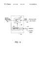
- FIG. 14is a diagram of a preferred form of equalizer for use in broadband digital communication systems to eliminate colored noise from the input of a slicer by using an error predictor circuit.
- FIG. 15is a diagram of a preferred form of error predictor for use in the equalizer of FIG. 14 .
- FIG. 1there is shown a typical CDMA receiver in which the invention may be usefully employed.
- the filtering system of the inventionis useful in any digital communication system using carriers and broadband waveforms where narrow bandwidth strong interfering signals can occur.
- Many spread spectrum systemsincluding not only direct sequence but also pulsed FM chirp systems transmit their signals using wide bandwidths.
- the inventionis useful to eliminate narrowband interference in any broad bandwidth communication system, and the claims are not intended to be limited to direct-sequence spread-spectrum CDMA systems transmitting digital data over cable TV media, although that is an environment in which the invention is useful.
- a headend or central unit(hereafter CU) is coupled to one or more remote units or RUs by a hybrid fiber coaxial cable network of a cable television system.
- a filter and down conversion circuit 10bandpass filters the analog signals on channel 12 using a passband centered on the upstream channel frequency if the receiver is in the CU.
- the passbandis centered on the downstream channel frequency if the receiver is in a remote unit or RU (frequency division multiplexing is assumed to separate upstream and downstream digital data spread spectrum analog signals on the shared channel).
- a down converter in circuit 10then converts the filtered analog signal back down to a baseband signal on line 14 .
- An analog-to-digital converter 16then samples the analog signal to generate a plurality of digital samples.
- a matched filter 18then digitally filters the samples back to their original pulse shapes. That is, the transfer function of a matched filter is the complex conjugate of the signal to which it is matched.
- a baseband digital matched filter having a transfer function matched to the transmitted signalacts as a synchronizer and act as conjugate signal generators when the signal to which the filter is matched appears at its input.
- the delay line based matched filteris intended to recognize a particular code sequence to which it is matched. Each delay segment has a delay equal to the period of the chip clock so that each segment contains energy corresponding to one chip in the sequence at any particular time.
- a despreader 20demultiplexes the spread spectrum signal using an inverse code matrix to the code matrix that was used in the transmitter to spread the symbol data.
- the resulting signal on line 22is input to an equalizer 24 which functions to correct for the non ideal channel response.
- the corrected output signal from the equalizeris error corrected by an error correction circuit using the redundant ECC bits added to the payload data in the transmitter.
- a framer circuit 28reassembles the data into frames or packets of the type used by the upper layer protocols such as by constructing MPEG2 packets from the error corrected data on line 30 .
- the resulting reframed datais output to the upper layer protocols for further processing on line 32 .
- the inventionemploys a filter circuit like that shown in FIG. 2 on bus 21 coupling the matched filter 18 to the despreader 20 .
- the narrow band interference excision filter of FIG. 2is comprised of a bank of narrow bandpass filters 34 each of which has a different center frequency and a passband which overlaps slightly with the passbands of its neighboring filters on either side so as to prevent blind spots.
- the function of the bank of bandpass filters 34is to provide a plurality of output signals each of which represents the energy of the incoming signal in a narrow frequency range corresponding to the passband limits of that particular filter. This allows narrow bandwidth interference signals to be isolated in individual frequency bins for analysis and excision.
- 256 individual subband filters with overlapping frequency responsesare used to cover a 4 MHz wide CDMA signal bandwidth. The number of filters used is a tradeoff depending upon the bandwidth to be covered, the amount of hardware complexity and associated cost that can be tolerated and the typical bandwidth of the interfering signals most commonly encountered.
- the frequency response selected for each filterwill be such that the subbands are not much wider than the most frequently encountered interference signal so as to prevent loss of useful signal information when an entire bin is suppressed because of the presence of an interference signal.
- use of fewer analysis filters with wider bandwidthsis acceptable because of a loose coupling between the bandwidth of the individual subbands and loss of payload data when an entire subband is suppressed. This result follows because the energy of the payload data is spread out among all bins so the loss of any one or a few of them is not radically damaging to recovery of data in the receiver.
- a detection and cancellation circuitAfter separating the input waveform into subband energy components in a plurality of narrow frequency ranges (hereafter referred to as bins), a detection and cancellation circuit examines each bin to determine if a narrow bandwidth interference signal is present in that bin. If so, the amplitude of all the signals in the bin is reduced to zero in the preferred embodiment. In other embodiments, the amplitude of all frequency components in the bin including is attenuated to some small amplitude. This reduces the amplitude of the narrow band interference source to a level which is low enough to insure that it will not cause enough interference to exceed the error detection and correction capability of the ECC bits added to the payload data.
- the method carried out by the detection and cancellation circuit of determining if a narrow band interference signal is present in a binis by computing the average power of all the signals in the bin or subband and comparing that average power to a threshold, preferably an adaptable threshold.
- a thresholdpreferably an adaptable threshold. This threshold is set so as to detect most instances of narrowband interference. If the power in a subband is found to exceed the threshold (the same threshold is used for every bin in SCDMA), then the magnitudes of all signal in that subband are set to zero.
- Another way of detecting the presence of an interfering signalis by taking an average of the absolute amplitudes of the waveform at each frequency in the bin. The absolute amplitude of the waveform at each frequency in the bin is then compared to this average.
- a peakis found with an amplitude which exceeds the average by more than some predetermined amount (a programmable value in some embodiments)
- the binis deemed to have an interference signal present.
- a predetermined amounta programmable value in some embodiments
- This notionworks in a CDMA system because spread spectrum systems are very wide bandwidth systems where the energy of the payload data is spread out over the wide bandwidth. This tends to cause the transmitted signal to have a power density similar to white noise. This means that every bin will have a signal in it that does not vary wildly in amplitude, and the average power of the signals in all bins will be almost the same. The higher the number of spreading codes that are used, the more true this becomes. Thus, a narrow bandwidth interference signal will stand out like the proverbial “sore thumb”.
- the calculation of the average absolute amplitude of the signal at each of the frequencies in each binis an adaptive process which is ongoing in real time. The same is true for each of the alternative methods described herein of determining when there is an interference signal present.
- an attenuator or other suitable circuitry in detection and cancellation circuit 36causes the amplitude of the waveform at all frequencies in this bin to be attenuated to zero or some other small value.
- FIG. 3illustrates this concept.
- a narrow bandwidth bandstop or notch filtermay be used instead of attenuating every frequency in the bin. If a digitally tunable notch filter is associated with each detection and cancellation circuit assigned to a particular bin, the comparison process, upon locating an interference peak in the bin, can send a digital parameter to the notch filter to center its notch on the center frequency of the interference signal.
- the comparison processdetermines how wide the bandwidth of the interference signal is as well as its center frequency, and sends digital parameters to the notch filter to move its center frequency to the center frequency of the interference and which also alter the frequency response of the notch filter to adjust the bandwidth of the stop band or notch to correspond with the bandwidth of the interference signal.
- the notch filters in detection and cancellation circuit 36may be in an array having one filter which is associated with each bin. Since it is unlikely that every bin will have an interference signal therein, it is also possible to save on hardware complexity and use an array of notch filters which is not as large as the number of bins. Individual filters in this array may be selectively connected to the individual conductors of bus 38 to excise the interference signals out of the signals on the individual lines of bus 38 in response to control data from the circuitry that does the detection process.
- an array of notch filtersmay be incorporated in the synthesis bank of filters so as to be selectively coupled to filter the combined output signal on line 42 in response to control data from the detection circuitry in block 36 .
- the switching circuitrymust be such that if two or more interfering signals are detected by the detection circuit 36 , a like number of notch filters may be tuned to have their notches centered on the center frequency of the interference signals and then connected in series with bus 42 to filter each interference signal out of the combined signal.
- Line 35represents the shape of the filter passband that creates the bin. This skirt shape is defined by the transfer function of the filter.
- the waveform of the spread spectrum signalis represented by signal 37 .
- the signal 41represents a narrowband interference signal.
- the dashed line 39represents the average power density of signals 41 and 37 combined by superposition.
- the detection and cancellation circuitcompares the average power of the combined signals 41 and 37 in the bin, and if the average power exceeds a a threshold, preferably an adaptable threshold, then the bin is deemed to contain an interfering signal, and all the signals in the subband are eliminated.
- the process carried out by the detection and cancellation circuitis carried out in every bin or subband created by the bank of filters 34 , so multiple interfering signals can be removed simultaneously.
- the average power of the waveformmay be calculated by squaring the amplitude of the amplitude at every frequency, summing the squares and dividing by the number of frequencies. The power of the waveform at every frequency is then compared to the average power for the bin, and if any frequency has a peak having a power level which is greater than a predetermined amount above the average, that bin is deemed to have an interfering signal.
- Another way of detecting an interfering signal in a binis to do a Fourier transform on the samples that define the waveform in every bin and then look at the resulting frequency components for noise peaks which exceed the average amplitude of the other frequency components in the bin by a predetermined amount.
- a processoris programmed to calculate a Fourier Transform of the signal in each subband and calculate the average amplitude of all the Fourier components in each subband, and, in each subband, compare the amplitudes of the Fourier components that result from the Fourier Transform calculation to the average amplitude of the Fourier components in the subband to determine if any component exceeds the average by more than a predetermined amount. Any subband which has one or more Fourier components that exceed the average by the predetermined amount is deemed to have narrowband interference present.
- Another way of detecting the presence of an interfering signalis to calculate the average absolute amplitude in the bin and then compute the variance of the amplitude from some variance threshold selected to give a reliable indication of the presence of narrowband interference. If any amplitude exceeds a predetermined amount of acceptable variance, the bin is deemed to have an interference signal present.
- Another way of detecting the presence of an interfering signalis to compute the average amplitude or power in each bin and compare the average to the average of the same averages of each of the other bins or subbands. Any bin with an interfering signal will have an average which is substantially higher than the averages of bins which do not have interfering signals present. If any bin has an average that is higher than the other averages by a predetermined (possibly programmable) amount, that bin is deemed to have an interfering signal present.
- the resulting signals in the subbands on the busesare input to a synthesis bank of filters 40 .
- the function of the synthesis bank of filtersis to put all the component signals in the time domain on buses 38 back together as a single composite signal on bus 42 .
- the combined system comprised of filter bank 34 , detection and cancellation circuit 36 and synthesis bank of filtersis called a quadrature mirror filter (QMF) bank comprised of known digital FIR filters for the analysis bank 34 and the synthesis bank 40 . Not just any FIR filters will work however for these two banks of filters. It is important that the coefficients of these filters be selected such that the combination of analysis and synthesis filters in the filter banks fall within the subclass of FIR filters called perfect reconstruction filters. This means that if the analysis bank and the synthesis bank are connected back to back (with the detection and cancellation circuit eliminated) the output signal generated from the samples output by the synthesis bank 40 on bus 42 would be identical to the input signal defined by the samples on bus 31 with some constant delay and constant gain present. Perfect reconstruction filters are used for best performance in the preferred embodiment of the invention. Although other filters could be used for the analysis and synthesis banks, the performance would not be optimal and may even be unacceptable.
- QMFquadrature mirror filter
- the “perfect reconstruction filters” that are preferredare not actually perfect. Because a finite resolution (the number of filters M in the analysis bank 34 is not infinite) and because the filter response of the analysis and synthesis filters is not perfect, even after excision and reconstruction, there will still be some residual interference on bus 42 . This interference can be modelled as colored noise. This colored noise will be eliminated by an error prediction circuit that will be described below. Since the main energy of the narrow band interference signal was eliminated by the QMF filter system, the assumption can be made that the error prediction system works with no decision errors.
- FIG. 4is a graph showing a typical set of frequency responses for the analysis filters of filter bank 34 .
- the preferred embodimentuses overlapping frequency responses defining the subbands to avoid blind spots, other embodiments can use marginally overlapping or non-overlapping frequency responses or frequency responses that overlap more than is shown.
- the number of analysis filters in the analysis bank 34determines the bandwidth of the frequency response of each filter.
- FIG. 5shows a more detailed block diagram of the QMF filter structure of FIG. 2 .
- the analysis bank of filters 34is comprised of a plurality of M narrow passband “brickwall” bandpass filters with very low side lobes designated hI where I increments from 0 to M ⁇ 1.
- Each of these filters(when combined with its paired synthesis filter less the intermediary detection and cancellation circuit) is a filter from the known subgenus of FIR filters known as “perfect reconstruction filters” or “near-perfect reconstruction filters” and is selected to have low side lobes in its frequency response.
- Many “brickwall filters” with sharp skirt rolloff and narrow passbandshave high side lobes.
- Low side lobesmeans that the frequency response has a passband like that shown in the idealized frequency response curve 35 in FIG. 3 with little side lobe activity to avoid signals or components having frequencies below F 1 or above F 2 through to the output.
- each of these filters 44 , 46 , 48 etc.is from the genus of FIR or digital finite impulse response filters, although digital IIR filters could also be used, and, if the receiver front end was analog, analog SAW filters could also be used.
- Decimators 50 , 52 and 54 etc.function to lower the sample rate.
- the sample rate of the wide band signal on bus 31has to be high enough to satisfy the Nyquist criterion to prevent aliasing.
- the FIR analysis filters 44 etc.modify the samples in accordance with their transfer function to output samples which define a narrow frequency band.
- the sample rateis maintained however, and it does not have to be that high when working with the narrow bandwidth subband signals. Therefore, each decimator lowers the sample rate by eliminating, for example, every other sample (decimation by two). This allows the circuitry to be simpler and less expensive to build.
- the decimatorsdecimate by a factor of M thereby taking only every Mth sample and ignoring the rest. There is no synchronization between the decimators as to which Mth samples in the sequences they receive they each take, i.e., the Mth samples taken by the sequence of decimators do not form a sequence of sequential samples.
- FIG. 6is a diagram of one embodiment for the detection and cancellation circuits 56 , 58 and 60 that comprise block 36 in FIG. 2 .
- the narrowband samplesarrive on bus 61 and are coupled to a detection circuit 64 that computes the average absolute amplitude or other criteria used or does an FFT on the samples from the bin.
- the detection circuitcontrols the position of a switch 66 via a control signal symbolized by dashed arrow 68 . If the detection circuit detects no interference signal present, it leaves switch 66 in the position shown so the samples pass unattenuated through the circuit and are output on bus 63 .
- signal 68is altered to cause switch 66 to connect bus 63 to terminal 70 which is connected to a null value thereby completely eliminating the samples on bus 61 from the group of samples that will be converted by synthesis bank 40 back into a single signal represented by a single group of samples.
- An alternative embodiment for the cancellation portion of the detection and cancellation circuitswould be a switching circuit which imposes an adaptable notch filter in the signal path when a narrowband interference source is found and sets the coefficients of the notch filter to substantially match the center frequency of the notch filter with the center frequency of the narrowband interference signal.
- the notch filtercould have a fixed bandwidth and attenuation value and in other embodiments, the bandwidth and/or attenuation value could be programmable or adaptable.
- the combination of FIR filters and decimators to the left of the detection and cancellation circuits in FIG. 5can be implemented as known polyphase filters which have lower complexity. This is made possible by lowering the sample rate using decimators 50 , 52 and 54 etc. and raising it back up using interpolators 72 , 74 and 76 etc. Further, the lower sample rate also reduces the complexity of the detection and correction circuits 56 , 58 and 60 etc. since each can work at a sample rate lower by a factor of M than the sample rate on bus 31 . For example, the detection circuit 64 will have to far fewer mathematical operations and comparisons to calculate the average amplitude or power or do an FFT where there are fewer samples per second.
- decimators and interpolatorscan be eliminated.
- interpolators 72 , 74 and 76The function of these interpolators is to raise the sample rate back up to the rate of bus 31 by inserting zeroes where the omitted samples were on each of buses 63 , 65 and 67 etc.
- the sample streams output by each of the interpolators 72 , 74 and 76 etc.are input to another filter gI forming part of the synthesis filter bank, of which filters 78 , 80 and 82 etc. are typical.
- Each of these gI filtersis preferably an FIR filter having a transfer function which is the inverse of the transfer function of its paired filter hI in the “perfect reconstruction filter”. If the two transfer functions were convolved in the time domain, the result would be one.
- the reason the system of FIG. 2 is called a Quadrature Mirror Filteris because the g filters each have transfer functions in the time domain which are each a mirror of the corresponding h filters.
- the inverse transfer functions between the h and g filtersare what makes the pair of filters a perfect reconstruction filter.
- polyphase filtersany digital filter regardless of the number of its coefficients can be broken down into a plurality of subfilters which, when their outputs are combined, yield the same signal as the original filter would have yielded.
- the equations defining the nature of polyphase filters and the Noble identityare well known, but are included here for completeness.
- H(z) and GI(z) in the frequency domainwhich define polyphase filters. They are related by the following relationship:
- block 80represents a standard filter having a frequency domain representation of its transfer function equal to H(z).
- Block 82represents a decimation by 2 where every other sample is eliminated.
- filter 84works on the nth sample
- filter 86works on the n ⁇ 1 sample with both filters working at the high sample rate of bus 94 .
- decimators 88 and 90are coupled to bus 94 and serve to lower the sample rate by a factor of 2 with their output sample streams coupled to the data inputs of two filters 96 and 98 having transfer functions in the frequency domain of G 0 (z) and G 1 (z), respectively, which are related by the equations above to the transfer functions H(z) of filter 80 in FIG. 7 .
- each of the 10 GI(z) filters in the structure like that of FIG. 9 which would result from using the Noble Identitywould each have one coefficient.
- filter 96would have the odd numbered coefficients and filter 98 would have the even numbered coefficients.
- Use of the polyphase filter technique in conjunction with application of the noble identityallows a simpler physical structure that can be implemented by less complex and expensive filters to implement the hI(n) and the gI(n) filters in FIG. 5 .
- the structure of FIG. 5can be implemented as the structure shown in FIG. 10 .
- a series of decimators 100 , 102 and 104 etc.down convert the sample rate on bus 31 by a factor of M.
- Each resulting streamis input to a separate data input of an analysis polyphase filter matrix 106 .
- This matrixis comprised of a collection of type 1 polyphase filters, each polyphase filter doing the job of a single hI(n) subband filter in FIG. 5 and having a structure such as is shown in FIG. 9 but expanded to whatever value is selected for M.
- the matrix of polyphase filters defined by this relationship to implement the bank of synthesis filtersis comprised of comprised of a plurality of rows, the first row starting with R00(z) and ending with R0,M ⁇ 1(z) and the first column 30 starting with R00(z) and ending with RM ⁇ 1,0(z), and the last row starting with RM ⁇ 1,0(z) and ending with RM ⁇ 1,M ⁇ 1(z).
- Each polyphase filterhas a separate output, represented by buses 108 , 110 etc. These outputs are coupled to separate inputs of a detection and cancellation matrix 112 which is comprised of a collection of individual detection and cancellation circuits such as those shown in FIG. 6 . Each detection and cancellation circuit has its own output, represented by buses 114 , 116 etc. These outputs are coupled to individual data inputs of a synthesis polyphase filter matrix comprised of a collection of type 2 polyphase filters, each type 2 polyphase filter doing the job of one of the gI(n) filters in FIG. 5 .
- the outputs of the synthesis polyphase filterssuch as buses 120 and 122 are coupled to data inputs of interpolators represented by blocks 124 , 126 etc. The output sample streams of the interpolators are combined on bus 128 for output to the rest of the receiver circuitry for despreading etc.
- FIG. 11illustrates one way of implementing the decimators 100 , 102 through 104 in FIG. 10 using a commutator switch represented by movable vector 130 .
- the input sample stream on bus 31enters the input of the switch.
- the individual data inputs 105 , 107 etc. of the analysis filter matrix 106are represented by the lines to the right of the movable vector 130 .
- the movable vector 130represents a switch arm that moves selectively to couple bus 31 to each one of the data inputs 105 , 107 through 109 in a sequence so that sequential digital samples are coupled to sequential data inputs.
- switch arm 130is symbolic of any form of electronic switching circuit that functions in the way described herein.
- the commutator switch armis operated so as to sequentially connect samples to sequential inputs. For example, when the ⁇ (M ⁇ 1) sample (the sample that arrived at the switch input M ⁇ 1 samples in time before the 0th sample) arrives at the input of switch 130 , switch 130 is operated to couple bus 31 to the Mth data input 109 . When the next sample arrives, the switch 130 is operated to couple the sample to the next data input up (not shown) in the sequence. When the ⁇ 1 sample arrives, (the sample just before the 0th sample), the switch 130 is operated to connect bus 31 to input 107 . When the 0th sample is present at the input to switch 130 , the switch is operated to connect bus 31 to input 105 .
- the switch 130recouples bus 31 to data input 109 such that the 1st sample is input to the analysis switch matrix on input 109 . This process is continued until the Mth sample arrives and is coupled to input 105 and so on.
- the commutator switch 132 used to implement the interpolators 124 , 126 through 129 shown in FIG. 12works in the same way as switch 130 to reassemble the distributed sample sequences on outputs 120 , 122 through 123 into a single sample sequence on bus 128 with a sample rate the same as the sample rate on bus 31 .
- the switches 132 and 130operate asynchronously however and there is no coordination between them.
- the notation used to define the symbols on outputs 120 , 122 and 123also is different than the notation used to define the symbols in FIG. 11 to indicate this asynchronous nature of operation.
- the symbol on the left of the seriesis the earliest in time.
- the symbol identified as ⁇ (M ⁇ 1)is the first symbol received.
- the symbol identified as 0is the first symbol received.
- the switch arm 132starts out in a position to couple output 123 to bus 128 when the first symbol (symbol 0 ) is received.
- the next symbol in time to be coupled to bus 128is symbol 1 (not shown) which arrives on the next line up from line 123 (also not shown).
- the switch 132continues to work its way up coupling each output line to bus 128 during successive symbol times which the M ⁇ 1 symbol being the last symbol to be coupled to bus 128 before switch 132 re-connects line 123 to bus 128 to transmit symbol M thereto.
- the specific perfect reconstruction filter that was selected for the preferred embodimentwas a bank of linear phase perfect reconstruction filters. Any of the other subclasses of perfect reconstruction filters will also work as will a different number of analysis filters.
- the actual filter coefficientswill be defined by the fact that 256 filters are used, each filter having 312 coefficients. The number of coefficients is also not critical, but 312 coefficients is believed now to be best. Any IIR perfect reconstruction filter will also suffice to practice the invention.
- the filter frequency response characteristicsshould overlap however to prevent blind spots regardless of whether FIR or IIR perfect reconstruction filters are used and regardless of which subclass is selected regardless of the number of filters or coefficients used.
- This structureis comprised of a feed forward equalizer 200 receiving input data, processing it and outputting revised data driving one input of a summer 202 .
- the difference input 210 of the summer 202is driven by a feedback equalizer 206 which takes its input from the output of a slicer 204 which has an input driven by the output of the summer.
- the basic concept upon which the inventive equalizer is builtis to “whiten” any colored noise on bus 212 by making modifications to the prior art equalizer. Colored noise will result on bus 212 if narrowband interference is present or even if narrowband interference is not present but FFE 200 is not perfect.
- the general scheme of modification to the prior art DFE equalizer to whiten the noise on bus 212is to add an error prediction circuit which functions to predict the next colored noise interval from the previous colored noise interval.
- the arrangement for the preferred form of equalizeris shown in FIG. 14 .
- Dataenters the equalizer 24 on line 22 and is processed by a conventional feed forward equalizer 200 .
- the output of the feed forward equalizer on line 212is coupled to the noninverting input of a summer 214 .
- the inverting input 210 of summer 214is coupled to the output of conventional feedback equalizer 206 .
- the input 208 of the feedback equalizeris coupled to the output of a conventional slicer 204 .
- the output of the summer 214 on bus 220has digital samples that define a signal which has both payload data plus white noise plus colored noise. It is the function of the equalizer 24 to “whiten” the colored noise so that it does not adversely affect detection of each symbol by the slicer.
- the equalizer whitens the colored noiseis as follows.
- the input samples on bus 22are processed by the feed forward equalizer 200 in a conventional manner to compensate for some impairments in the channel.
- the output of the feed forward equalizer on bus 212is summed with the output on bus 210 of a feedback equalizer 206 in summer 214 in a conventional manner.
- the output of summer 214 on bus 220is summed with correction data on bus 222 in summer 224 , and the output data is input to conventional slicer 204 .
- the sliceroutputs the actual data transmitted.
- the data on bus 23is applied to the input 208 of the feedback equalizer 206 which processes it in conventional fashion to generate the feedback equalization data on bus 210 .
- the whitening of the colored noisestarts by coupling the signals on bus 220 to the noninverting input of a summer 226 .
- the signals on bus 220will include data, white noise and colored noise.
- the output data from the slicer on bus 23which is data only, is coupled to the inverting input of the summer 226 .
- the summer 226functions to subtract the data only signal on bus 23 from the combined data, white noise and colored noise signals on bus 220 .
- the resulting signals on bus 228are white noise and colored noise only. These signals are input to an error predictor circuit 230 .
- the error predictor circuitis an adaptive digital FIR filter which has its coefficients adapted by the process of correlation of the colored noise.
- FIG. 15is a block diagram of the error predictor 230 .
- the function of the error predictor circuitis to adapt the coefficients of its FIR filter in accordance with the correlation of the colored noise so as to predict the colored noise.
- the resulting data output on bus 222is applied to the inverting input of summer 224 to subtract out the colored noise from the signals on bus 220 so as to eliminate colored noise at the input 232 of the slicer.
- the adaptive FIR filteris shown at 234 . Its input is coupled to receive the white noise and colored noise signals on bus 228 .
- the coefficients of the FIR filterare adjusted by data on bus 236 output by a coefficient adaptation circuit 238 .
- a summer 240receives the data plus white noise plus some colored noise on bus 232 (assuming the colored noise has not yet been canceled).
- the inverting input of summer 240is coupled to bus 23 to receive the data.
- the summersubtracts this data from the data, white noise and colored noise on bus 232 to output a signal on bus 242 which is white noise and any residual colored noise.
- the signals on bus 242are input to the coefficient adaptation circuit 238 in FIG. 15 .
- the coefficient adaptation circuit 238will generate a nonzero correlation signal on bus 236 thereby adapting the coefficients of the filter 234 in a direction to generate an output signal on bus 222 which is data and white noise and causes summer 224 to subtract out at least some of the colored noise on bus 220 .
- the adaption processcontinues changing the coefficients of the filter 234 until a signal on bus 222 causes cancellation of all the colored noise at the input 232 of the slicer. This is the desired state of convergence since the power of the colored noise is now minimum.
- the signals on bus 232will be data plus white noise only, and the signals on bus 242 will be white noise only.
- the output of the correlator on bus 236will be zero so no further adaptation of the filter coefficients occurs between samples. This causes the filter output on bus 222 to remain at a stable sample value adequate to remove colored noise from the signals on bus 220 .
- the convergence processstarts again until the new or altered colored noise signals are removed from the input signals to the slicer by summer 224 .
Landscapes
- Engineering & Computer Science (AREA)
- Computer Networks & Wireless Communication (AREA)
- Signal Processing (AREA)
- Noise Elimination (AREA)
- Filters That Use Time-Delay Elements (AREA)
- Cable Transmission Systems, Equalization Of Radio And Reduction Of Echo (AREA)
Abstract
Description
Claims (23)
Priority Applications (4)
| Application Number | Priority Date | Filing Date | Title |
|---|---|---|---|
| US09/152,645US6426983B1 (en) | 1998-09-14 | 1998-09-14 | Method and apparatus of using a bank of filters for excision of narrow band interference signal from CDMA signal |
| CA002281863ACA2281863A1 (en) | 1998-09-14 | 1999-09-09 | Method and apparatus of using a bank of filters for excision of narrow band interference signal from cdma signal |
| JP11257995AJP2000101479A (en) | 1998-09-14 | 1999-09-10 | Method and device for using filter banks for removal of interference signal of narrow band from cdma signal |
| EP99660146AEP0987829A3 (en) | 1998-09-14 | 1999-09-14 | Method and apparatus for excision of narrow band interference signal from CDMA signal |
Applications Claiming Priority (1)
| Application Number | Priority Date | Filing Date | Title |
|---|---|---|---|
| US09/152,645US6426983B1 (en) | 1998-09-14 | 1998-09-14 | Method and apparatus of using a bank of filters for excision of narrow band interference signal from CDMA signal |
Publications (1)
| Publication Number | Publication Date |
|---|---|
| US6426983B1true US6426983B1 (en) | 2002-07-30 |
Family
ID=22543785
Family Applications (1)
| Application Number | Title | Priority Date | Filing Date |
|---|---|---|---|
| US09/152,645Expired - LifetimeUS6426983B1 (en) | 1998-09-14 | 1998-09-14 | Method and apparatus of using a bank of filters for excision of narrow band interference signal from CDMA signal |
Country Status (4)
| Country | Link |
|---|---|
| US (1) | US6426983B1 (en) |
| EP (1) | EP0987829A3 (en) |
| JP (1) | JP2000101479A (en) |
| CA (1) | CA2281863A1 (en) |
Cited By (163)
| Publication number | Priority date | Publication date | Assignee | Title |
|---|---|---|---|---|
| US20020011828A1 (en)* | 2000-06-27 | 2002-01-31 | Alon Wallach | Electromagnetic radiation alerting device for use with a cellular telephone |
| US20020057751A1 (en)* | 1999-04-28 | 2002-05-16 | Lockheed Martin Corporation | Interference detection, identification, extraction and reporting |
| US20020073436A1 (en)* | 2000-08-16 | 2002-06-13 | Nicholas Paul Cowley | Tuner |
| US20020155812A1 (en)* | 2001-03-09 | 2002-10-24 | Masatoshi Takada | Interference-signal removing apparatus |
| US20020198913A1 (en)* | 2001-06-25 | 2002-12-26 | Johnson Russell K. | Parallel decimator adaptive filter and method for all-rate gigabit-per-second modems |
| US20030028374A1 (en)* | 2001-07-31 | 2003-02-06 | Zlatan Ribic | Method for suppressing noise as well as a method for recognizing voice signals |
| US20030076888A1 (en)* | 2001-05-07 | 2003-04-24 | Cindy Daniell | Signal processing subband coder architecture |
| US20030161418A1 (en)* | 2002-02-22 | 2003-08-28 | Greg Steele | Blind narrow-band interference canceller using a prediction error method |
| US6622044B2 (en)* | 2001-01-04 | 2003-09-16 | Cardiac Pacemakers Inc. | System and method for removing narrowband noise |
| US20030210734A1 (en)* | 2002-05-07 | 2003-11-13 | Takashi Kaku | Noise elimination method and apparatus |
| US6662367B2 (en)* | 1995-02-06 | 2003-12-09 | Adc Telecommunications, Inc. | Poly-phase filters in multicarrier communication systems |
| US20040028124A1 (en)* | 2002-07-30 | 2004-02-12 | Jukka Nuutinen | Method of operating a communications system and a communications system |
| US20040042557A1 (en)* | 2002-08-29 | 2004-03-04 | Kabel Allan M. | Partial band reconstruction of frequency channelized filters |
| US20040052314A1 (en)* | 2002-08-26 | 2004-03-18 | Texas Instruments Incorporated | Crest factor reduction processor for wireless communications |
| US6718166B2 (en) | 2002-05-17 | 2004-04-06 | Illinois Superconductor Corporation, Inc. | Multiple carrier adaptive notch filter |
| WO2004032347A1 (en)* | 2002-08-28 | 2004-04-15 | Agency For Science Technology And Research | Receiver having a signal reconstructing section for noise reduction, system and method thereof |
| US20040146127A1 (en)* | 2003-01-28 | 2004-07-29 | Kent Samuel D. | Mixed technology MEMS/SiGe BiCMOS digitizing analog front end with direct RF sampling |
| US20040203551A1 (en)* | 2002-08-09 | 2004-10-14 | Junsong Li | Noise blanker using an adaptive all-pole predictor and method therefor |
| WO2004079975A3 (en)* | 2003-03-03 | 2004-10-28 | Interdigital Tech Corp | Multi user detection using equalization and successive interference cancellation |
| US20040228426A1 (en)* | 2003-05-12 | 2004-11-18 | Jeong-Tae Oh | Apparatus and method for cancelling narrow-band interference in a mobile communication system |
| US20040261118A1 (en)* | 2003-06-18 | 2004-12-23 | General Instrument Corporation | Narrowband interference and identification and digital processing for cable television return path performance enhancement |
| US20050018796A1 (en)* | 2003-07-07 | 2005-01-27 | Sande Ravindra Kumar | Method of combining an analysis filter bank following a synthesis filter bank and structure therefor |
| US20050031097A1 (en)* | 1999-04-13 | 2005-02-10 | Broadcom Corporation | Gateway with voice |
| US6856653B1 (en)* | 1999-11-26 | 2005-02-15 | Matsushita Electric Industrial Co., Ltd. | Digital signal sub-band separating/combining apparatus achieving band-separation and band-combining filtering processing with reduced amount of group delay |
| US20050047487A1 (en)* | 2003-09-01 | 2005-03-03 | Gcomm Corporation | Spread spectrum communication system receiving device |
| US6867728B1 (en) | 2003-11-06 | 2005-03-15 | Lockheed Martin Corporation | Methods and systems for identifying signals-of-interest |
| US20050104767A1 (en)* | 2002-01-08 | 2005-05-19 | Estelle Kirby | Device and method for the suppression of pulsed wireless signals |
| US20050190867A1 (en)* | 2004-03-01 | 2005-09-01 | Sobchak Charles L. | Low cost and high performance narrowband interference cancellation system |
| US20050271120A1 (en)* | 2004-06-02 | 2005-12-08 | Lockheed Martin Corporation | Detector for time-hopped impulse radio |
| US20050281321A1 (en)* | 2004-06-17 | 2005-12-22 | Bergstrom Chad S | Method and apparatus for distributed polyphase spread spectrum communications |
| US20050286619A1 (en)* | 2004-06-28 | 2005-12-29 | Haddadin Osama S | Parallel DSP demodulation for wideband software-defined radios |
| US6985492B1 (en)* | 1999-04-13 | 2006-01-10 | Broadcom Corporation | Voice gateway with voice synchronization |
| US20060029142A1 (en)* | 2004-07-15 | 2006-02-09 | Oren Arad | Simplified narrowband excision |
| US20060171445A1 (en)* | 2005-01-28 | 2006-08-03 | Texas Instruments Incorporated | Methods and systems for detecting and mitigating interference for a wireless device |
| US20060176965A1 (en)* | 2005-02-07 | 2006-08-10 | Harris Corporation | System and method for removing interfering narrowband signals from wide bandwidth receive signal |
| US20060215795A1 (en)* | 2001-01-30 | 2006-09-28 | Texas Instruments Incorporated | Interference cancellation of a narrow bank interferer in a wide band communication device |
| US20070076782A1 (en)* | 2005-09-30 | 2007-04-05 | Freescale Semiconductor, Inc. | Method and system for controlling a notching mechanism |
| US7203545B2 (en) | 2001-01-04 | 2007-04-10 | Cardiac Pacemakers, Inc. | System and method for receiving telemetry data from an implantable medical device |
| US20070093604A1 (en)* | 2003-07-01 | 2007-04-26 | Joseph Kennedy | Thermoplastic elastomeric multiblock copolymers of isobutylene and norbornene |
| US20070127558A1 (en)* | 2005-12-06 | 2007-06-07 | Banister Brian C | Interference cancellation with improved estimation and tracking for wireless communication |
| US20070153878A1 (en)* | 2006-01-04 | 2007-07-05 | Filipovic Daniel F | Spur suppression for a receiver in a wireless communication system |
| US7245651B1 (en)* | 1999-12-20 | 2007-07-17 | Intel Corporation | Dual mode filter for mobile telecommunications |
| US7292830B1 (en)* | 2004-03-31 | 2007-11-06 | Nortel Networks Limited | Receiver gain management |
| US20070286264A1 (en)* | 2006-06-07 | 2007-12-13 | Nokia Corporation | Interference reduction in spread spectrum receivers |
| US20080043649A1 (en)* | 2006-08-17 | 2008-02-21 | Texas Instruments Incorporated | Reliable Packet Detection In A Wireless Receiver When Packets Contain A Known Repetitive Sequence |
| US20080043888A1 (en)* | 2006-08-17 | 2008-02-21 | Texas Instruments Incorporated | Eliminating narrowband interference in a receiver |
| US20080049853A1 (en)* | 2000-03-09 | 2008-02-28 | Franceschini Michael R | Frequency Domain Direct Sequence Spread Spectrum with Flexible Time Frequency Code |
| US7339504B1 (en)* | 2002-11-29 | 2008-03-04 | Silicon Laboratories Inc. | Communications device with asynchronous sample rate converter |
| US20080088736A1 (en)* | 2006-10-16 | 2008-04-17 | Thomson Licensing | Co-channel interference detector |
| US20080170646A1 (en)* | 2007-01-11 | 2008-07-17 | Freescale Semiconductor, Inc. | Automatic gain control using multiple equalized estimates and dynamic hysteresis |
| US20080260070A1 (en)* | 2004-08-03 | 2008-10-23 | Agency For Science, Technology And Research | Method for Transmitting a Digital Signal, Method for Receiving a Digital Signal, Transmitter and Receiver |
| US20080317113A1 (en)* | 2004-06-10 | 2008-12-25 | Adnan Al Adnani | System and Method for Run-Time Reconfiguration |
| US20090074036A1 (en)* | 2002-05-22 | 2009-03-19 | Interdigital Technology Corporation | Segment-wise channel equalization based data estimation |
| US20090186587A1 (en)* | 2008-01-23 | 2009-07-23 | Freescale Semiconductor, Inc. | Tuning a second order intercept point of a mixer in a receiver |
| US20090296841A1 (en)* | 2008-05-30 | 2009-12-03 | Commissariat A L' Energie Atomique | Method for detecting an ofdm signal |
| US20100020235A1 (en)* | 2006-11-01 | 2010-01-28 | Aaron Reel Bouillet | Co-channel interference remover |
| US20100067620A1 (en)* | 2003-03-03 | 2010-03-18 | Interdigital Technology Corporation | Reduced complexity sliding window based equalizer |
| US20100118921A1 (en)* | 2008-11-11 | 2010-05-13 | Isco International, Inc. | Self-Adaptive Digital RF Bandpass and Bandstop Filter Architecture |
| US20100124252A1 (en)* | 2008-11-18 | 2010-05-20 | Electronics And Telecommunications Research Institute | Apparatus and method for communication |
| US20100177857A1 (en)* | 2007-05-25 | 2010-07-15 | Nokia Corporation | Interference in communication devices |
| US20100191525A1 (en)* | 1999-04-13 | 2010-07-29 | Broadcom Corporation | Gateway With Voice |
| US20100195775A1 (en)* | 2009-02-03 | 2010-08-05 | Harris Corporation | Communications device including a filter for notching wideband receive signals and associated methods |
| USRE41771E1 (en) | 1995-02-06 | 2010-09-28 | Adc Telecommunications, Inc. | System for multiple use subchannels |
| US20100316108A1 (en)* | 2009-06-15 | 2010-12-16 | Novatek Microelectronics Corp. | Device and method of data recovery |
| US7856063B2 (en) | 2003-06-25 | 2010-12-21 | Industrial Research Limited | Narrowband interference suppression for OFDM systems |
| US20100329321A1 (en)* | 2009-06-30 | 2010-12-30 | Stmicroelectronics S.R.L. | Electronic device for receiving a radio-frequency signal |
| DE102009025218A1 (en)* | 2009-06-17 | 2010-12-30 | Rohde & Schwarz Gmbh & Co. Kg | Method and apparatus for signal analysis and synthesis |
| US20110053546A1 (en)* | 2009-08-20 | 2011-03-03 | Alfred E. Mann Foundation For Scientific Research | Optimal narrowband interference removal for signals separated in time |
| KR101021569B1 (en)* | 2003-03-03 | 2011-03-16 | 인터디지탈 테크날러지 코포레이션 | Sliding window-based equalizer with reduced complexity |
| USRE42236E1 (en) | 1995-02-06 | 2011-03-22 | Adc Telecommunications, Inc. | Multiuse subcarriers in multipoint-to-point communication using orthogonal frequency division multiplexing |
| US20110081243A1 (en)* | 2009-10-02 | 2011-04-07 | Sullivan John T | Helical airfoil wind turbines |
| US20110116536A1 (en)* | 2009-11-18 | 2011-05-19 | Yih-Ming Tsuie | Narrow-band interference detector, signal receiver employing narrow-band interference detector and controlling demodulator parameter setting according to narrow-band interference detection result, and related methods thereof |
| US20110158360A1 (en)* | 2009-12-30 | 2011-06-30 | Man-On Pun | SNR-Based Blanking Scheme for Impulsive Noise Mitigation in Wireless Networks |
| KR20120033325A (en)* | 2009-07-16 | 2012-04-06 | 소니 주식회사 | Communications system using adaptive frequency notching |
| US8295415B2 (en) | 2004-12-02 | 2012-10-23 | Mstar Semiconductor, Inc. | Interference characterisation and removal |
| US8971307B2 (en) | 2012-12-20 | 2015-03-03 | Cisco Technology, Inc. | Noise ingress cancelation |
| US20150085962A1 (en)* | 2012-06-27 | 2015-03-26 | Andrew Llc | Canceling narrowband interfering signals in a distributed antenna system |
| US9048919B2 (en) | 2008-11-11 | 2015-06-02 | Isco International Llc | Method and apparatus for an adaptive filter architecture |
| US20150279386A1 (en)* | 2014-03-31 | 2015-10-01 | Google Inc. | Situation dependent transient suppression |
| US9209857B2 (en) | 2013-03-15 | 2015-12-08 | Isco International, Llc | Method and apparatus for signal interference processing |
| US20160043835A1 (en)* | 2011-05-26 | 2016-02-11 | Cohere Technologies, Inc. | Modulation and equalization in an orthonormal time-frequency shifting communications system |
| WO2016183230A1 (en)* | 2015-05-11 | 2016-11-17 | Cohere Technologies | Systems and methods for symplectic orthogonal time frequency shifting modulation and transmission of data |
| US9503154B2 (en)* | 2015-01-30 | 2016-11-22 | Trellisware Technologies, Inc. | Methods and systems for interference estimation via quantization in spread-spectrum systems |
| CN104320159B (en)* | 2009-07-16 | 2017-01-04 | 索尼公司 | communication system and method of operating a communication system |
| US20170026107A1 (en)* | 2014-04-08 | 2017-01-26 | Commscope Technologies Llc | Digital repeater system |
| US20170048004A1 (en)* | 2014-04-29 | 2017-02-16 | Huawei Technologies Co., Ltd. | Signal receiving method and receiver |
| US9621175B2 (en) | 2015-02-11 | 2017-04-11 | Syntropy Systems, Llc | Sampling/quantization converters |
| US9654128B2 (en)* | 2010-01-05 | 2017-05-16 | Syntropy Systems, Llc | Multi-mode sampling/quantization converters |
| US9660851B2 (en) | 2010-05-28 | 2017-05-23 | Cohere Technologies, Inc. | Modulation and equalization in an orthonormal time-frequency shifting communications system |
| US9668223B2 (en) | 2014-05-05 | 2017-05-30 | Isco International, Llc | Method and apparatus for increasing performance of communication links of communication nodes |
| CN106797234A (en)* | 2016-09-09 | 2017-05-31 | 香港应用科技研究院有限公司 | Interference Detection and Cancellation for Power Line Communications |
| US9712354B2 (en) | 2010-05-28 | 2017-07-18 | Cohere Technologies, Inc. | Modulation and equalization in an orthonormal time-frequency shifting communications system |
| US9831970B1 (en)* | 2010-06-10 | 2017-11-28 | Fredric J. Harris | Selectable bandwidth filter |
| US9866363B2 (en) | 2015-06-18 | 2018-01-09 | Cohere Technologies, Inc. | System and method for coordinated management of network access points |
| CN104144138B (en)* | 2013-05-10 | 2018-01-26 | 钜泉光电科技(上海)股份有限公司 | Adaptive single-frequency arrowband interference notch filter device and double frequency filter apparatus |
| US9893922B2 (en) | 2012-06-25 | 2018-02-13 | Cohere Technologies, Inc. | System and method for implementing orthogonal time frequency space communications using OFDM |
| US9900048B2 (en) | 2010-05-28 | 2018-02-20 | Cohere Technologies, Inc. | Modulation and equalization in an orthonormal time-frequency shifting communications system |
| US9929783B2 (en)* | 2012-06-25 | 2018-03-27 | Cohere Technologies, Inc. | Orthogonal time frequency space modulation system |
| US9935664B1 (en)* | 2015-10-21 | 2018-04-03 | Marvell International Ltd. | Signal detection and power measurement with multi-band filter to mitigate narrowband interference |
| US9942020B1 (en)* | 2017-04-26 | 2018-04-10 | Cisco Technology, Inc. | Minimum delay spatio-temporal filtering for interference rejection |
| US9967758B2 (en) | 2012-06-25 | 2018-05-08 | Cohere Technologies, Inc. | Multiple access in an orthogonal time frequency space communication system |
| US10003487B2 (en) | 2013-03-15 | 2018-06-19 | Cohere Technologies, Inc. | Symplectic orthogonal time frequency space modulation system |
| US10020854B2 (en) | 2012-06-25 | 2018-07-10 | Cohere Technologies, Inc. | Signal separation in an orthogonal time frequency space communication system using MIMO antenna arrays |
| US10063295B2 (en) | 2016-04-01 | 2018-08-28 | Cohere Technologies, Inc. | Tomlinson-Harashima precoding in an OTFS communication system |
| US10063354B2 (en) | 2010-05-28 | 2018-08-28 | Cohere Technologies, Inc. | Modulation and equalization in an orthonormal time-frequency shifting communications system |
| US10090973B2 (en) | 2015-05-11 | 2018-10-02 | Cohere Technologies, Inc. | Multiple access in an orthogonal time frequency space communication system |
| US10164684B2 (en)* | 2016-09-09 | 2018-12-25 | Hong Kong Applied Science and Technology Research Institute Company Limited | Interference detection and mitigation in power line communication |
| US10298279B2 (en) | 2017-04-05 | 2019-05-21 | Isco International, Llc | Method and apparatus for increasing performance of communication paths for communication nodes |
| US10334457B2 (en) | 2010-05-28 | 2019-06-25 | Cohere Technologies, Inc. | OTFS methods of data channel characterization and uses thereof |
| US10355887B2 (en) | 2016-04-01 | 2019-07-16 | Cohere Technologies, Inc. | Iterative two dimensional equalization of orthogonal time frequency space modulated signals |
| US10356632B2 (en) | 2017-01-27 | 2019-07-16 | Cohere Technologies, Inc. | Variable beamwidth multiband antenna |
| US10374844B1 (en)* | 2018-03-08 | 2019-08-06 | Nxp B.V. | Signal-equalization with noise-whitening filter |
| US10411843B2 (en) | 2012-06-25 | 2019-09-10 | Cohere Technologies, Inc. | Orthogonal time frequency space communication system compatible with OFDM |
| US10469215B2 (en) | 2012-06-25 | 2019-11-05 | Cohere Technologies, Inc. | Orthogonal time frequency space modulation system for the Internet of Things |
| US10555281B2 (en) | 2016-03-31 | 2020-02-04 | Cohere Technologies, Inc. | Wireless telecommunications system for high-mobility applications |
| US10568143B2 (en) | 2017-03-28 | 2020-02-18 | Cohere Technologies, Inc. | Windowed sequence for random access method and apparatus |
| US10574317B2 (en) | 2015-06-18 | 2020-02-25 | Cohere Technologies, Inc. | System and method for providing wireless communication services using configurable broadband infrastructure shared among multiple network operators |
| US10652835B2 (en) | 2016-06-01 | 2020-05-12 | Isco International, Llc | Signal conditioning to mitigate interference impacting wireless communication links in radio access networks |
| US10666314B2 (en) | 2016-02-25 | 2020-05-26 | Cohere Technologies, Inc. | Reference signal packing for wireless communications |
| US10666479B2 (en) | 2015-12-09 | 2020-05-26 | Cohere Technologies, Inc. | Pilot packing using complex orthogonal functions |
| US10667148B1 (en) | 2010-05-28 | 2020-05-26 | Cohere Technologies, Inc. | Methods of operating and implementing wireless communications systems |
| US10681568B1 (en) | 2010-05-28 | 2020-06-09 | Cohere Technologies, Inc. | Methods of data channel characterization and uses thereof |
| US10687284B2 (en) | 2014-05-05 | 2020-06-16 | Isco International, Llc | Method and apparatus for increasing performance of communication paths for communication nodes |
| US10693692B2 (en) | 2016-03-23 | 2020-06-23 | Cohere Technologies, Inc. | Receiver-side processing of orthogonal time frequency space modulated signals |
| US10693581B2 (en) | 2015-07-12 | 2020-06-23 | Cohere Technologies, Inc. | Orthogonal time frequency space modulation over a plurality of narrow band subcarriers |
| US10749651B2 (en) | 2016-03-31 | 2020-08-18 | Cohere Technologies, Inc. | Channel acquistion using orthogonal time frequency space modulated pilot signal |
| US10826728B2 (en) | 2016-08-12 | 2020-11-03 | Cohere Technologies, Inc. | Localized equalization for channels with intercarrier interference |
| US10833783B2 (en) | 2017-08-09 | 2020-11-10 | Isco International, Llc | Method and apparatus for monitoring, detecting, testing, diagnosing and/or mitigating interference in a communication system |
| US10855425B2 (en) | 2017-01-09 | 2020-12-01 | Cohere Technologies, Inc. | Pilot scrambling for channel estimation |
| CN112105033A (en)* | 2020-07-30 | 2020-12-18 | 国家无线电监测中心哈尔滨监测站 | Broadband spectrum reconstruction method for using frequency competition situation |
| US10873418B2 (en) | 2016-08-12 | 2020-12-22 | Cohere Technologies, Inc. | Iterative multi-level equalization and decoding |
| US10892547B2 (en) | 2015-07-07 | 2021-01-12 | Cohere Technologies, Inc. | Inconspicuous multi-directional antenna system configured for multiple polarization modes |
| US10917204B2 (en) | 2016-08-12 | 2021-02-09 | Cohere Technologies, Inc. | Multi-user multiplexing of orthogonal time frequency space signals |
| US10938602B2 (en) | 2016-05-20 | 2021-03-02 | Cohere Technologies, Inc. | Iterative channel estimation and equalization with superimposed reference signals |
| US10938613B2 (en) | 2015-06-27 | 2021-03-02 | Cohere Technologies, Inc. | Orthogonal time frequency space communication system compatible with OFDM |
| US10951454B2 (en) | 2017-11-01 | 2021-03-16 | Cohere Technologies, Inc. | Precoding in wireless systems using orthogonal time frequency space multiplexing |
| US10965348B2 (en) | 2016-09-30 | 2021-03-30 | Cohere Technologies, Inc. | Uplink user resource allocation for orthogonal time frequency space modulation |
| US11025377B2 (en) | 2016-12-05 | 2021-06-01 | Cohere Technologies, Inc. | Fixed wireless access using orthogonal time frequency space modulation |
| US11038733B2 (en) | 2015-11-18 | 2021-06-15 | Cohere Technologies, Inc. | Orthogonal time frequency space modulation techniques |
| US11063804B2 (en) | 2017-04-24 | 2021-07-13 | Cohere Technologies, Inc. | Digital communication using lattice division multiplexing |
| US11070329B2 (en) | 2015-09-07 | 2021-07-20 | Cohere Technologies, Inc. | Multiple access using orthogonal time frequency space modulation |
| US11102034B2 (en) | 2017-09-06 | 2021-08-24 | Cohere Technologies, Inc. | Lattice reduction in orthogonal time frequency space modulation |
| US11114768B2 (en) | 2017-04-24 | 2021-09-07 | Cohere Technologies, Inc. | Multibeam antenna designs and operation |
| US11147087B2 (en) | 2017-04-21 | 2021-10-12 | Cohere Technologies, Inc. | Communication techniques using quasi-static properties of wireless channels |
| US11152957B2 (en) | 2017-09-29 | 2021-10-19 | Cohere Technologies, Inc. | Forward error correction using non-binary low density parity check codes |
| US11184122B2 (en) | 2017-12-04 | 2021-11-23 | Cohere Technologies, Inc. | Implementation of orthogonal time frequency space modulation for wireless communications |
| US11190308B2 (en) | 2017-09-15 | 2021-11-30 | Cohere Technologies, Inc. | Achieving synchronization in an orthogonal time frequency space signal receiver |
| US11190379B2 (en) | 2017-07-12 | 2021-11-30 | Cohere Technologies, Inc. | Data modulation schemes based on the Zak transform |
| US11283561B2 (en) | 2017-09-11 | 2022-03-22 | Cohere Technologies, Inc. | Wireless local area networks using orthogonal time frequency space modulation |
| US11310000B2 (en) | 2016-09-29 | 2022-04-19 | Cohere Technologies, Inc. | Transport block segmentation for multi-level codes |
| US11324008B2 (en) | 2017-08-14 | 2022-05-03 | Cohere Technologies, Inc. | Transmission resource allocation by splitting physical resource blocks |
| US11329848B2 (en) | 2018-06-13 | 2022-05-10 | Cohere Technologies, Inc. | Reciprocal calibration for channel estimation based on second-order statistics |
| CN114598353A (en)* | 2022-03-10 | 2022-06-07 | 中国电子科技集团公司第三十八研究所 | A method and device for interference suppression based on perfect subband segmentation |
| US11362693B2 (en) | 2017-08-09 | 2022-06-14 | Isco International, Llc | Method and apparatus for detecting and analyzing passive intermodulation interference in a communication system |
| US11489559B2 (en) | 2018-03-08 | 2022-11-01 | Cohere Technologies, Inc. | Scheduling multi-user MIMO transmissions in fixed wireless access systems |
| US11532891B2 (en) | 2017-09-20 | 2022-12-20 | Cohere Technologies, Inc. | Low cost electromagnetic feed network |
| US11546068B2 (en) | 2017-08-11 | 2023-01-03 | Cohere Technologies, Inc. | Ray tracing technique for wireless channel measurements |
| US11632270B2 (en) | 2018-02-08 | 2023-04-18 | Cohere Technologies, Inc. | Aspects of channel estimation for orthogonal time frequency space modulation for wireless communications |
| US11817987B2 (en) | 2017-04-11 | 2023-11-14 | Cohere Technologies, Inc. | Digital communication using dispersed orthogonal time frequency space modulated signals |
| US11831391B2 (en) | 2018-08-01 | 2023-11-28 | Cohere Technologies, Inc. | Airborne RF-head system |
| US11943089B2 (en) | 2010-05-28 | 2024-03-26 | Cohere Technologies, Inc. | Modulation and equalization in an orthonormal time-shifting communications system |
| US12335081B2 (en) | 2021-04-29 | 2025-06-17 | Cohere Technologies, Inc. | Ultra wide band signals using orthogonal time frequency space modulation |
| EP4593295A1 (en) | 2024-01-23 | 2025-07-30 | Airbus Defence and Space GmbH | Method and apparatus for compression of signal dynamic range of a radiofrequency (rf) signal |
Families Citing this family (20)
| Publication number | Priority date | Publication date | Assignee | Title |
|---|---|---|---|---|
| US6512803B2 (en) | 2000-04-05 | 2003-01-28 | Symmetricom, Inc. | Global positioning system receiver capable of functioning in the presence of interference |
| DE10030583A1 (en)* | 2000-06-21 | 2002-01-10 | Marconi Comm Gmbh | Device and method for processing frequency signals |
| JP3385266B2 (en) | 2000-11-27 | 2003-03-10 | 富士通株式会社 | Noise removal method and apparatus |
| FR2820869B1 (en) | 2001-02-13 | 2003-11-07 | Thomson Csf | MATRIX DISPLAY DEVICE WITH PROXIMITY DETECTION |
| JP3427381B2 (en)* | 2001-06-20 | 2003-07-14 | 富士通株式会社 | Noise cancellation method and apparatus |
| KR100474709B1 (en) | 2001-12-10 | 2005-03-08 | 삼성전자주식회사 | Device and method for cancelling narrow-band interference in wireless communication systems |
| US7944995B2 (en)* | 2005-11-14 | 2011-05-17 | Telefonaktiebolaget Lm Ericsson (Publ) | Variable bandwidth receiver |
| FI20065010A0 (en)* | 2006-01-09 | 2006-01-09 | Nokia Corp | Interference suppression in a telecommunication system |
| KR20090086976A (en)* | 2006-11-01 | 2009-08-14 | 톰슨 라이센싱 | Co-channel interference detector |
| US7986922B2 (en)* | 2006-12-15 | 2011-07-26 | Qualcomm Incorporated | Jammer detection and suppression for wireless communication |
| FR2911461A1 (en)* | 2007-01-17 | 2008-07-18 | St Microelectronics Sa | Incident analog signal filtering and converting method for radiofrequency signal receiver, involves performing digital filtering of reshaped signal for filtering frequency components outside desired frequency range |
| FR2911462B1 (en) | 2007-01-17 | 2009-06-26 | St Microelectronics Sa | METHOD AND DEVICE FOR FILTERING AND ANALOG / DIGITAL CONVERSION OF ANALOG SIGNAL. |
| WO2008126356A1 (en)* | 2007-03-29 | 2008-10-23 | Panasonic Corporation | Ofdm receiving device and ofdm receiving method |
| JP4535145B2 (en)* | 2008-02-26 | 2010-09-01 | ソニー株式会社 | Communication device, noise removal method, and program |
| RU2493648C2 (en)* | 2008-12-01 | 2013-09-20 | РОКСТАР КОНСОРЦИУМ ЮЭс ЛП | Method for frequency-dependent suppression of signals and apparatus for realising said method (versions) |
| EP2541783B1 (en)* | 2010-02-25 | 2020-11-04 | Mitsubishi Electric Corporation | Interference wave suppression device, relay device, relay system, and interference wave suppression method |
| EP2711735B1 (en)* | 2011-05-16 | 2018-10-10 | Furuno Electric Co., Ltd. | Interference wave signal removal device, gnss receiver device, mobile terminal, interference wave signal removal program, and interference wave signal removal method |
| CN106161301A (en)* | 2015-03-30 | 2016-11-23 | 索尼公司 | Apparatus and method in wireless communication system and wireless communication system |
| CN111854930B (en)* | 2020-07-21 | 2022-10-14 | 长春理工大学 | Vibration signal power frequency interference suppression method based on priori estimation |
| CN119182418B (en)* | 2024-11-22 | 2025-03-07 | 北京融为科技有限公司 | Method, device and apparatus for detecting narrowband interference signal in spread spectrum signal |
Citations (2)
| Publication number | Priority date | Publication date | Assignee | Title |
|---|---|---|---|---|
| US3988679A (en)* | 1973-05-04 | 1976-10-26 | General Electric Company | Wideband receiving system including multi-channel filter for eliminating narrowband interference |
| US5325204A (en)* | 1992-05-14 | 1994-06-28 | Hitachi America, Ltd. | Narrowband interference cancellation through the use of digital recursive notch filters |
Family Cites Families (2)
| Publication number | Priority date | Publication date | Assignee | Title |
|---|---|---|---|---|
| US4613978A (en)* | 1984-06-14 | 1986-09-23 | Sperry Corporation | Narrowband interference suppression system |
| US5612978A (en)* | 1995-05-30 | 1997-03-18 | Motorola, Inc. | Method and apparatus for real-time adaptive interference cancellation in dynamic environments |
- 1998
- 1998-09-14USUS09/152,645patent/US6426983B1/ennot_activeExpired - Lifetime
- 1999
- 1999-09-09CACA002281863Apatent/CA2281863A1/ennot_activeAbandoned
- 1999-09-10JPJP11257995Apatent/JP2000101479A/enactivePending
- 1999-09-14EPEP99660146Apatent/EP0987829A3/ennot_activeWithdrawn
Patent Citations (2)
| Publication number | Priority date | Publication date | Assignee | Title |
|---|---|---|---|---|
| US3988679A (en)* | 1973-05-04 | 1976-10-26 | General Electric Company | Wideband receiving system including multi-channel filter for eliminating narrowband interference |
| US5325204A (en)* | 1992-05-14 | 1994-06-28 | Hitachi America, Ltd. | Narrowband interference cancellation through the use of digital recursive notch filters |
Non-Patent Citations (3)
| Title |
|---|
| "Analysis of DFT-Based Frequency Excision Algorithms for Direct-Sequence Spread-Spectrum Communication", Jeffrey A. Young and James S. Lehnert, IEEE Transactions on Communications, vol. 46, No. 8, Aug. 1998, pp. 1076-1087. |
| A. Ranheim, "Narrowband Interference Rejection in Direct Sequence Spread Spectrum System Using Time-Frequency Decomposition, 8049i IEEE Proceedings-Communications, 1442 (1995 Dec., No. 6, pp. 393-400". |
| Proceedings of the IEEE Third International Symposium on Spread Spectrum Techniques & Application, ISEEE ISSSTA '94, Jul. 4-6, 1994, University of Oulu, Oulu, Finland, vol. 2/2, pp. 521-525. |
Cited By (489)
| Publication number | Priority date | Publication date | Assignee | Title |
|---|---|---|---|---|
| USRE44460E1 (en) | 1994-09-26 | 2013-08-27 | Htc Corporation | Systems for synchronous multipoint-to-point orthogonal frequency division multiplexing communication |
| US8638655B2 (en) | 1994-09-26 | 2014-01-28 | Htc Corporation | Systems and method for orthogonal frequency divisional multiplexing |
| US8547824B2 (en) | 1994-09-26 | 2013-10-01 | Htc Corporation | Systems and methods for orthogonal frequency divisional multiplexing |
| US8174956B2 (en) | 1995-02-06 | 2012-05-08 | Htc Corporation | Systems and method for orthogonal frequency divisional multiplexing |
| US8213399B2 (en) | 1995-02-06 | 2012-07-03 | Htc Corporation | System for multiple use subchannels |
| USRE41771E1 (en) | 1995-02-06 | 2010-09-28 | Adc Telecommunications, Inc. | System for multiple use subchannels |
| US7936662B2 (en) | 1995-02-06 | 2011-05-03 | Adc Telecommunications, Inc. | Ranging and round trip delay timing adjustment in a multi-point to point bidirectional communication system |
| US7773537B2 (en) | 1995-02-06 | 2010-08-10 | Adc Telecommunications, Inc. | Ranging and round trip delay timing adjustment in a multi-point to point bidirectional communication system |
| US7957265B2 (en) | 1995-02-06 | 2011-06-07 | Adc Telecommunications, Inc. | Systems and method for orthogonal frequency divisional multiplexing |
| US7983141B2 (en) | 1995-02-06 | 2011-07-19 | Geile Michael J | Synchronized multipoint-to-point communication using orthogonal frequency division |
| US6662367B2 (en)* | 1995-02-06 | 2003-12-09 | Adc Telecommunications, Inc. | Poly-phase filters in multicarrier communication systems |
| US7995454B2 (en) | 1995-02-06 | 2011-08-09 | Htc Corporation | Systems and method for orthogonal frequency divisional multiplexing |
| US7756060B2 (en) | 1995-02-06 | 2010-07-13 | Adc Telecommunications, Inc. | Tone allocation in multipoint-to-point communication using orthogonal frequency division multiplexing |
| US8089853B2 (en) | 1995-02-06 | 2012-01-03 | Htc Corporation | Systems and method for orthogonal frequency divisional multiplexing |
| US7872985B2 (en) | 1995-02-06 | 2011-01-18 | Adc Dsl Systems, Inc. | System for multi-frame alignment |
| US8199632B2 (en) | 1995-02-06 | 2012-06-12 | Htc Corporation | Systems and method for orthogonal frequency divisional multiplexing |
| US7912138B2 (en) | 1995-02-06 | 2011-03-22 | Adc Telecommunications, Inc. | Timing and symbol alignment in multipoint-to-point communication using orthogonal frequency division multiplexing |
| US7706349B2 (en) | 1995-02-06 | 2010-04-27 | Adc Telecommunications, Inc. | Methods and systems for selecting modulation in an orthogonal frequency division multiplexing system |
| US7697453B2 (en) | 1995-02-06 | 2010-04-13 | Adc Telecommunications, Inc. | Synchronization techniques in multipoint-to-point communication using orthogonal frequency division multiplexing |
| US8213398B2 (en) | 1995-02-06 | 2012-07-03 | Htc Corporation | Method for multiple use subchannels |
| US7675843B2 (en) | 1995-02-06 | 2010-03-09 | Adc Telecommunications, Inc. | Multipoint-to-point communication using orthogonal frequency division multiplexing |
| US7672219B2 (en) | 1995-02-06 | 2010-03-02 | Adc Telecommunications, Inc. | Multipoint-to-point communication using orthogonal frequency division multiplexing |
| US8315150B2 (en) | 1995-02-06 | 2012-11-20 | Htc Corporation | Synchronized multipoint-to-point communication using orthogonal frequency division |
| US8351321B2 (en) | 1995-02-06 | 2013-01-08 | Htc Corporation | Systems and method for orthogonal frequency divisional multiplexing |
| US8406115B2 (en) | 1995-02-06 | 2013-03-26 | Htc Corporation | Systems and methods for orthogonal frequency division multiplexing |
| USRE42236E1 (en) | 1995-02-06 | 2011-03-22 | Adc Telecommunications, Inc. | Multiuse subcarriers in multipoint-to-point communication using orthogonal frequency division multiplexing |
| US7881181B2 (en) | 1995-02-06 | 2011-02-01 | Adc Telecommunications, Inc. | Systems and method for orthogonal frequency divisional multiplexing |
| US7535822B2 (en) | 1995-02-06 | 2009-05-19 | Adc Telecommunications, Inc. | Synchronization of remote units for a communication network |
| US8576693B2 (en) | 1995-02-06 | 2013-11-05 | Htc Corporation | Systems and method for orthogonal frequency division multiplexing |
| US7881180B2 (en) | 1995-02-06 | 2011-02-01 | Adc Telecommunications, Inc. | Systems and method for orthogonal frequency divisional multiplexing |
| US7310522B2 (en) | 1996-05-20 | 2007-12-18 | Adc Telecommunications, Inc. | Systems for synchronous multipoint-to-point orthogonal frequency division multiplexing communication |
| US8948141B2 (en) | 1999-02-02 | 2015-02-03 | Isco International, Llc | Method and device for maintaining the performance quality of a communication system in the presence of narrow band interference |
| US8750258B2 (en) | 1999-02-02 | 2014-06-10 | Isco International, Llc | Method and device for maintaining the performance quality of a communication system in the presence of narrow band interference |
| US10039117B2 (en)* | 1999-02-02 | 2018-07-31 | Isco International, Llc | Method and device for maintaining the performance quality of a communication system in the presence of narrow band interference |
| US9894662B2 (en)* | 1999-02-02 | 2018-02-13 | Isco International, Llc | Method and device for maintaining the performance quality of a communication system in the presence of narrow band interference |
| US9100867B2 (en)* | 1999-02-02 | 2015-08-04 | Isco International, Llc | Method and device for maintaining the performance quality of a communication system in the presence of narrow band interference |
| US9100860B2 (en) | 1999-02-02 | 2015-08-04 | Isco International, Llc | Method and device for maintaining the performance quality of a communication system in the presence of narrow band interference |
| US9100850B2 (en)* | 1999-02-02 | 2015-08-04 | Isco International, Llc | Method and device for maintaining the performance quality of a communication system in the presence of narrow band interference |
| US20150214998A1 (en)* | 1999-02-02 | 2015-07-30 | Isco International, Llc | Method and device for maintaining the performance quality of a communication system in the presence of narrow band interference |
| US9788331B2 (en) | 1999-02-02 | 2017-10-10 | Isco International, Llc | Method and device for maintaining the performance quality of a communication system in the presence of narrow band interference |
| US20150194990A1 (en)* | 1999-02-02 | 2015-07-09 | Isco International, Llc | Method and device for maintaining the performance quality of a communication system in the presence of narrow band interference |
| US20170280464A1 (en)* | 1999-02-02 | 2017-09-28 | Isco International, Llc | Method and device for maintaining the performance quality of a communication system in the presence of narrow band interference |
| US9706559B2 (en)* | 1999-02-02 | 2017-07-11 | Isco International, Llc | Method and device for maintaining the performance quality of a communication system in the presence of narrow band interference |
| US20150139012A1 (en)* | 1999-02-02 | 2015-05-21 | Isco International, Llc | Method and device for maintaining the performance quality of a communication system in the presence of narrow band interference |
| US20150139013A1 (en)* | 1999-02-02 | 2015-05-21 | Isco International, Llc | Method and device for maintaining the performance quality of a communication system in the presence of narrow band interference |
| US20150139077A1 (en)* | 1999-02-02 | 2015-05-21 | Isco International, Llc | Method and device for maintaining the performance quality of a communication system in the presence of narrow band interference |
| US20160353455A1 (en)* | 1999-02-02 | 2016-12-01 | Isco International, Llc | Method and device for maintaining the performance quality of a communication system in the presence of narrow band interference |
| US20120275492A1 (en)* | 1999-02-02 | 2012-11-01 | Isco International, Llc | Method and device for maintaining the performance quality of a communication system in the presence of narrow band interference |
| US9031509B2 (en) | 1999-02-02 | 2015-05-12 | Isco International, Llc | Method and device for maintaining the performance quality of a communication system in the presence of narrow band interference |
| US9451495B2 (en)* | 1999-02-02 | 2016-09-20 | Isco International, Llc | Method and device for maintaining the performance quality of a communication system in the presence of narrow band interference |
| US20160100327A1 (en)* | 1999-02-02 | 2016-04-07 | Isco International, Llc | Method and device for maintaining the performance quality of a communication system in the presence of narrow band interference |
| US9025571B2 (en) | 1999-02-02 | 2015-05-05 | Isco International, Llc | Method and device for maintaining the performance quality of a communication system in the presence of narrow band interference |
| US9026057B2 (en) | 1999-02-02 | 2015-05-05 | Isco International, Llc | Method and device for maintaining the performance quality of a communication system in the presence of narrow band interference |
| US20120281731A1 (en)* | 1999-02-02 | 2012-11-08 | Isco International, Llc | Method and device for maintaining the performance quality of a communication system in the presence of narrow band interference |
| US9014100B2 (en)* | 1999-02-02 | 2015-04-21 | Isco International, Llc | Method and device for maintaining the performance quality of a communication system in the presence of narrow band interference |
| US8976700B2 (en)* | 1999-02-02 | 2015-03-10 | Isco International, Llc | Method and device for maintaining the performance quality of a communication system in the presence of narrow band interference |
| US20120309438A1 (en)* | 1999-02-02 | 2012-12-06 | Isco International, Llc | Method and device for maintaining the performance quality of a communication system in the presence of narrow band interference |
| US8971207B2 (en)* | 1999-02-02 | 2015-03-03 | Isco International, Llc | Method and device for maintaining the performance quality of a communication system in the presence of narrow band interference |
| US9247553B2 (en) | 1999-02-02 | 2016-01-26 | Isco International, Llc | Method and device for maintaining the performance quality of a communication system in the presence of narrow band interference |
| US9100859B2 (en) | 1999-02-02 | 2015-08-04 | Isco International, Llc | Method and device for maintaining the performance quality of a communication system in the presence of narrow band interference |
| US8948328B2 (en)* | 1999-02-02 | 2015-02-03 | Isco International, Llc | Method and device for maintaining the performance quality of a communication system in the presence of narrow band interference |
| US20140328197A1 (en)* | 1999-02-02 | 2014-11-06 | Isco International, Llc | Method and device for maintaining the performance quality of a communication system in the presence of narrow band interference |
| US9107224B2 (en)* | 1999-02-02 | 2015-08-11 | Isco International, Llc | Method and device for maintaining the performance quality of a communication system in the presence of narrow band interference |
| US9232423B2 (en)* | 1999-02-02 | 2016-01-05 | Isco International, Llc | Method and device for maintaining the performance quality of a communication system in the presence of narrow band interference |
| US8873464B2 (en) | 1999-02-02 | 2014-10-28 | Isco International, Llc | Method and device for maintaining the performance quality of a communication system in the presence of narrow band interference |
| US20140233461A1 (en)* | 1999-02-02 | 2014-08-21 | Isco International, Llc | Method and device for maintaining the performance quality of a communication system in the presence of narrow band interference |
| US8792833B2 (en) | 1999-02-02 | 2014-07-29 | Isco International, Llc | Method and device for maintaining the performance quality of a communication system in the presence of narrow band interference |
| US20140198887A1 (en)* | 1999-02-02 | 2014-07-17 | Isco International, Llc | Method and device for maintaining the performance quality of a communication system in the presence of narrow band interference |
| US8780808B2 (en)* | 1999-02-02 | 2014-07-15 | Isco International, Llc | Method and device for maintaining the performance quality of a communication system in the presence of narrow band interference |
| US9215719B2 (en) | 1999-02-02 | 2015-12-15 | Isco International, Llc | Method and device for maintaining the performance quality of a communication system in the presence of narrow band interference |
| US8774723B2 (en) | 1999-02-02 | 2014-07-08 | Isco International, Llc | Method and device for maintaining the performance quality of a communication system in the presence of narrow band interference |
| US9215723B2 (en) | 1999-02-02 | 2015-12-15 | Isco International, Llc | Method and device for maintaining the performance quality of a communication system in the presence of narrow band interference |
| US8767628B2 (en)* | 1999-02-02 | 2014-07-01 | Isco International, Llc | Method and device for maintaining the performance quality of a communication system in the presence of narrow band interference |
| US8750259B2 (en) | 1999-02-02 | 2014-06-10 | Isco International, Llc | Method and device for maintaining the performance quality of a communication system in the presence of narrow band interference |
| US9198055B2 (en)* | 1999-02-02 | 2015-11-24 | Isco International, Llc | Method and device for maintaining the performance quality of a communication system in the presence of narrow band interference |
| US8576808B2 (en) | 1999-02-02 | 2013-11-05 | Isco International, Llc | Method and device for maintaining the performance quality of a communication system in the presence of narrow band interference |
| US8743842B2 (en) | 1999-02-02 | 2014-06-03 | Isco International, Llc | Method and device for maintaining the performance quality of a communication system in the presence of narrow band interference |
| US8634386B2 (en) | 1999-02-02 | 2014-01-21 | Isco International, Llc | Method and device for maintaining the performance quality of a communication system in the presence of narrow band interference |
| US8724552B2 (en)* | 1999-02-02 | 2014-05-13 | Isco International, Llc | Method and device for maintaining the performance quality of a communication system in the presence of narrow band interference |
| US8718024B2 (en) | 1999-02-02 | 2014-05-06 | Isco International, Llc | Method and device for maintaining the performance quality of a communication system in the presence of narrow band interference |
| US20100191525A1 (en)* | 1999-04-13 | 2010-07-29 | Broadcom Corporation | Gateway With Voice |
| US20050031097A1 (en)* | 1999-04-13 | 2005-02-10 | Broadcom Corporation | Gateway with voice |
| US6985492B1 (en)* | 1999-04-13 | 2006-01-10 | Broadcom Corporation | Voice gateway with voice synchronization |
| US8254404B2 (en) | 1999-04-13 | 2012-08-28 | Broadcom Corporation | Gateway with voice |
| US20080160916A1 (en)* | 1999-04-28 | 2008-07-03 | Isco International, Inc. | Interference Detection, Identification, Extraction and Reporting |
| US20020057751A1 (en)* | 1999-04-28 | 2002-05-16 | Lockheed Martin Corporation | Interference detection, identification, extraction and reporting |
| US6807405B1 (en)* | 1999-04-28 | 2004-10-19 | Isco International, Inc. | Method and a device for maintaining the performance quality of a code-division multiple access system in the presence of narrow band interference |
| US7317698B2 (en)* | 1999-04-28 | 2008-01-08 | Isco International, Inc. | Interference detection, identification, extraction and reporting |
| US6856653B1 (en)* | 1999-11-26 | 2005-02-15 | Matsushita Electric Industrial Co., Ltd. | Digital signal sub-band separating/combining apparatus achieving band-separation and band-combining filtering processing with reduced amount of group delay |
| US7245651B1 (en)* | 1999-12-20 | 2007-07-17 | Intel Corporation | Dual mode filter for mobile telecommunications |
| US20080049853A1 (en)* | 2000-03-09 | 2008-02-28 | Franceschini Michael R | Frequency Domain Direct Sequence Spread Spectrum with Flexible Time Frequency Code |
| US20080219211A1 (en)* | 2000-03-09 | 2008-09-11 | Franceschini Michael R | Frequency Domain Direct Sequence Spread Spectrum with Flexible Time Frequency Code |
| US20020011828A1 (en)* | 2000-06-27 | 2002-01-31 | Alon Wallach | Electromagnetic radiation alerting device for use with a cellular telephone |
| US6934515B2 (en)* | 2000-06-27 | 2005-08-23 | Wireless Avionics Ltd. | Electromagnetic radiation alerting device for use with a cellular telephone |
| US20020073436A1 (en)* | 2000-08-16 | 2002-06-13 | Nicholas Paul Cowley | Tuner |
| US7016739B2 (en) | 2001-01-04 | 2006-03-21 | Cardiac Pacemakers, Inc. | System and method for removing narrowband noise |
| US20040030364A1 (en)* | 2001-01-04 | 2004-02-12 | Cardiac Pacemakers, Inc. | System and method for removing narrowband noise |
| US8768483B2 (en) | 2001-01-04 | 2014-07-01 | Cardiac Pacemakers, Inc. | System and method for receiving telemetry data from an implantable medical device |
| US7551965B2 (en) | 2001-01-04 | 2009-06-23 | Cardiac Pacemakers, Inc. | System and method for removing narrowband noise |
| US6622044B2 (en)* | 2001-01-04 | 2003-09-16 | Cardiac Pacemakers Inc. | System and method for removing narrowband noise |
| US8489197B2 (en)* | 2001-01-04 | 2013-07-16 | Cardiac Pacemakers, Inc. | System and method for receiving telemetry data from an implantable medical device |
| US20070135865A1 (en)* | 2001-01-04 | 2007-06-14 | Cardiac Pacemakers, Inc. | System and method for receiving telemetry data from an implantable medical device |
| US7203545B2 (en) | 2001-01-04 | 2007-04-10 | Cardiac Pacemakers, Inc. | System and method for receiving telemetry data from an implantable medical device |
| US20060215795A1 (en)* | 2001-01-30 | 2006-09-28 | Texas Instruments Incorporated | Interference cancellation of a narrow bank interferer in a wide band communication device |
| US20020155812A1 (en)* | 2001-03-09 | 2002-10-24 | Masatoshi Takada | Interference-signal removing apparatus |
| US20030076888A1 (en)* | 2001-05-07 | 2003-04-24 | Cindy Daniell | Signal processing subband coder architecture |
| US7046854B2 (en)* | 2001-05-07 | 2006-05-16 | Hrl Laboratories, Llc | Signal processing subband coder architecture |
| US6889238B2 (en)* | 2001-06-25 | 2005-05-03 | Lockheed Martin Corporation | Parallel decimator adaptive filter and method for all-rate gigabit-per-second modems |
| US20020198913A1 (en)* | 2001-06-25 | 2002-12-26 | Johnson Russell K. | Parallel decimator adaptive filter and method for all-rate gigabit-per-second modems |
| US7092877B2 (en)* | 2001-07-31 | 2006-08-15 | Turk & Turk Electric Gmbh | Method for suppressing noise as well as a method for recognizing voice signals |
| US20030028374A1 (en)* | 2001-07-31 | 2003-02-06 | Zlatan Ribic | Method for suppressing noise as well as a method for recognizing voice signals |
| US20050104767A1 (en)* | 2002-01-08 | 2005-05-19 | Estelle Kirby | Device and method for the suppression of pulsed wireless signals |
| US7161528B2 (en)* | 2002-01-08 | 2007-01-09 | Thales | Device and method for the suppression of pulsed wireless signals |
| US20030161418A1 (en)* | 2002-02-22 | 2003-08-28 | Greg Steele | Blind narrow-band interference canceller using a prediction error method |
| US20030210734A1 (en)* | 2002-05-07 | 2003-11-13 | Takashi Kaku | Noise elimination method and apparatus |
| US7173959B2 (en)* | 2002-05-07 | 2007-02-06 | Fujitsu Limited | Noise elimination method and apparatus |
| US6718166B2 (en) | 2002-05-17 | 2004-04-06 | Illinois Superconductor Corporation, Inc. | Multiple carrier adaptive notch filter |
| US20090074036A1 (en)* | 2002-05-22 | 2009-03-19 | Interdigital Technology Corporation | Segment-wise channel equalization based data estimation |
| US7609750B2 (en) | 2002-05-22 | 2009-10-27 | Interdigital Technology Corporation | Segment-wise channel equalization based data estimation |
| US20090323769A1 (en)* | 2002-05-22 | 2009-12-31 | Interdigital Technology Corporation | Segment-wise channel equalization based data estimation |
| US8085832B2 (en) | 2002-05-22 | 2011-12-27 | Interdigital Technology Corporation | Segment-wise channel equalization based data estimation |
| US20040028124A1 (en)* | 2002-07-30 | 2004-02-12 | Jukka Nuutinen | Method of operating a communications system and a communications system |
| US20040203551A1 (en)* | 2002-08-09 | 2004-10-14 | Junsong Li | Noise blanker using an adaptive all-pole predictor and method therefor |
| US7260163B2 (en)* | 2002-08-09 | 2007-08-21 | Freescale Semiconductor, Inc. | Noise blanker using an adaptive all-pole predictor and method therefor |
| US20040052314A1 (en)* | 2002-08-26 | 2004-03-18 | Texas Instruments Incorporated | Crest factor reduction processor for wireless communications |
| WO2004019540A3 (en)* | 2002-08-26 | 2004-05-27 | Texas Instruments Inc | Crest factor reduction processor for wireless communications |
| US7697591B2 (en)* | 2002-08-26 | 2010-04-13 | Texas Instruments Incorporated | Crest factor reduction processor for wireless communications |
| WO2004032347A1 (en)* | 2002-08-28 | 2004-04-15 | Agency For Science Technology And Research | Receiver having a signal reconstructing section for noise reduction, system and method thereof |
| WO2004023781A3 (en)* | 2002-08-29 | 2004-07-08 | Bae Systems Information | Partial band reconstruction of frequency channelized filters |
| US6792057B2 (en)* | 2002-08-29 | 2004-09-14 | Bae Systems Information And Electronic Systems Integration Inc | Partial band reconstruction of frequency channelized filters |
| US20040042557A1 (en)* | 2002-08-29 | 2004-03-04 | Kabel Allan M. | Partial band reconstruction of frequency channelized filters |
| US7339504B1 (en)* | 2002-11-29 | 2008-03-04 | Silicon Laboratories Inc. | Communications device with asynchronous sample rate converter |
| US20040146127A1 (en)* | 2003-01-28 | 2004-07-29 | Kent Samuel D. | Mixed technology MEMS/SiGe BiCMOS digitizing analog front end with direct RF sampling |
| US7187735B2 (en)* | 2003-01-28 | 2007-03-06 | Raytheon Company | Mixed technology MEMS/SiGe BiCMOS digitalized analog front end with direct RF sampling |
| KR101065426B1 (en)* | 2003-03-03 | 2011-09-19 | 인터디지탈 테크날러지 코포레이션 | Sliding window-based equalizer with reduced complexity |
| US20100067620A1 (en)* | 2003-03-03 | 2010-03-18 | Interdigital Technology Corporation | Reduced complexity sliding window based equalizer |
| WO2004079975A3 (en)* | 2003-03-03 | 2004-10-28 | Interdigital Tech Corp | Multi user detection using equalization and successive interference cancellation |
| KR101021569B1 (en)* | 2003-03-03 | 2011-03-16 | 인터디지탈 테크날러지 코포레이션 | Sliding window-based equalizer with reduced complexity |
| US20090316759A1 (en)* | 2003-03-03 | 2009-12-24 | Interdigital Technology Corporation | Multi-user detection using equalization and successive interference cancellation |
| US7593461B2 (en) | 2003-03-03 | 2009-09-22 | Interdigital Technology Corporation | Multi-user detection using equalization and successive interference cancellation |
| US8542772B2 (en) | 2003-03-03 | 2013-09-24 | InterDigital Technologies, Inc. | Multi-user detection using equalization and successive interference cancellation |
| CN1754321B (en)* | 2003-03-03 | 2010-12-08 | 美商内数位科技公司 | Method and equipment for radio communication |
| KR100805761B1 (en) | 2003-03-03 | 2008-02-21 | 인터디지탈 테크날러지 코포레이션 | Multiple User Detection with Equalization and Continuous Interference Cancellation |
| US20040223538A1 (en)* | 2003-03-03 | 2004-11-11 | Interdigital Technology Corporation | Multi user detection using equalization and successive interference cancellation |
| US20080240207A1 (en)* | 2003-03-03 | 2008-10-02 | Interdigital Technology Corporation | Multi-user detection using equalization and successive interference cancellation |
| US7346103B2 (en) | 2003-03-03 | 2008-03-18 | Interdigital Technology Corporation | Multi user detection using equalization and successive interference cancellation |
| US8249191B2 (en) | 2003-03-03 | 2012-08-21 | Interdigital Technology Corporation | Multi-user detection using equalization and successive interference cancellation |
| US20040228426A1 (en)* | 2003-05-12 | 2004-11-18 | Jeong-Tae Oh | Apparatus and method for cancelling narrow-band interference in a mobile communication system |
| US7716712B2 (en)* | 2003-06-18 | 2010-05-11 | General Instrument Corporation | Narrowband interference and identification and digital processing for cable television return path performance enhancement |
| US20040261118A1 (en)* | 2003-06-18 | 2004-12-23 | General Instrument Corporation | Narrowband interference and identification and digital processing for cable television return path performance enhancement |
| US7856063B2 (en) | 2003-06-25 | 2010-12-21 | Industrial Research Limited | Narrowband interference suppression for OFDM systems |
| US20070093604A1 (en)* | 2003-07-01 | 2007-04-26 | Joseph Kennedy | Thermoplastic elastomeric multiblock copolymers of isobutylene and norbornene |
| US20050018796A1 (en)* | 2003-07-07 | 2005-01-27 | Sande Ravindra Kumar | Method of combining an analysis filter bank following a synthesis filter bank and structure therefor |
| US20050047487A1 (en)* | 2003-09-01 | 2005-03-03 | Gcomm Corporation | Spread spectrum communication system receiving device |
| US6867728B1 (en) | 2003-11-06 | 2005-03-15 | Lockheed Martin Corporation | Methods and systems for identifying signals-of-interest |
| US20050190867A1 (en)* | 2004-03-01 | 2005-09-01 | Sobchak Charles L. | Low cost and high performance narrowband interference cancellation system |
| US7324616B2 (en)* | 2004-03-01 | 2008-01-29 | Motorola, Inc. | Low cost and high performance narrowband interference cancellation system |
| US7292830B1 (en)* | 2004-03-31 | 2007-11-06 | Nortel Networks Limited | Receiver gain management |
| US20050271120A1 (en)* | 2004-06-02 | 2005-12-08 | Lockheed Martin Corporation | Detector for time-hopped impulse radio |
| US20080317113A1 (en)* | 2004-06-10 | 2008-12-25 | Adnan Al Adnani | System and Method for Run-Time Reconfiguration |
| US20050281321A1 (en)* | 2004-06-17 | 2005-12-22 | Bergstrom Chad S | Method and apparatus for distributed polyphase spread spectrum communications |
| US7327777B2 (en)* | 2004-06-17 | 2008-02-05 | General Dynamics Corporation | Method and apparatus for distributed polyphase spread spectrum communications |
| US20050286619A1 (en)* | 2004-06-28 | 2005-12-29 | Haddadin Osama S | Parallel DSP demodulation for wideband software-defined radios |
| US7697641B2 (en)* | 2004-06-28 | 2010-04-13 | L-3 Communications | Parallel DSP demodulation for wideband software-defined radios |
| US20060029142A1 (en)* | 2004-07-15 | 2006-02-09 | Oren Arad | Simplified narrowband excision |
| US7573947B2 (en) | 2004-07-15 | 2009-08-11 | Terayon Communication Systems, Inc. | Simplified narrowband excision |
| US20080069258A1 (en)* | 2004-07-15 | 2008-03-20 | Oren Arad | Simplified narrowband excision |
| WO2006020132A3 (en)* | 2004-07-15 | 2006-06-08 | Terayon Comm Systems Inc | Simplified narrowband excision |
| US20080260070A1 (en)* | 2004-08-03 | 2008-10-23 | Agency For Science, Technology And Research | Method for Transmitting a Digital Signal, Method for Receiving a Digital Signal, Transmitter and Receiver |
| US8218694B2 (en) | 2004-08-03 | 2012-07-10 | Agency For Science, Technology And Research | Method for transmitting a digital signal, method for receiving a digital signal, transmitter and receiver |
| US8295415B2 (en) | 2004-12-02 | 2012-10-23 | Mstar Semiconductor, Inc. | Interference characterisation and removal |
| WO2006081559A3 (en)* | 2005-01-28 | 2006-09-28 | Texas Instruments Inc | Methods and systems for detecting and mitigating interference for a wireless device |
| US20060171445A1 (en)* | 2005-01-28 | 2006-08-03 | Texas Instruments Incorporated | Methods and systems for detecting and mitigating interference for a wireless device |
| US7372890B2 (en)* | 2005-01-28 | 2008-05-13 | Texas Instruments Incorporated | Methods and systems for detecting and mitigating interference for a wireless device |
| US7512197B2 (en) | 2005-02-07 | 2009-03-31 | Harris Corporation | System and method for removing interfering narrowband signals from wide bandwidth receive signal |
| US20060176965A1 (en)* | 2005-02-07 | 2006-08-10 | Harris Corporation | System and method for removing interfering narrowband signals from wide bandwidth receive signal |
| US7502410B2 (en)* | 2005-09-30 | 2009-03-10 | Freescale Semiconductor, Inc. | Method and system for controlling a notching mechanism |
| US20070076782A1 (en)* | 2005-09-30 | 2007-04-05 | Freescale Semiconductor, Inc. | Method and system for controlling a notching mechanism |
| US8630378B2 (en)* | 2005-12-06 | 2014-01-14 | Qualcomm Incorporated | Interference cancellation with improved estimation and tracking for wireless communication |
| US20070127558A1 (en)* | 2005-12-06 | 2007-06-07 | Banister Brian C | Interference cancellation with improved estimation and tracking for wireless communication |
| US8149896B2 (en) | 2006-01-04 | 2012-04-03 | Qualcomm, Incorporated | Spur suppression for a receiver in a wireless communication system |
| US20070153878A1 (en)* | 2006-01-04 | 2007-07-05 | Filipovic Daniel F | Spur suppression for a receiver in a wireless communication system |
| US20070286264A1 (en)* | 2006-06-07 | 2007-12-13 | Nokia Corporation | Interference reduction in spread spectrum receivers |
| US20080043649A1 (en)* | 2006-08-17 | 2008-02-21 | Texas Instruments Incorporated | Reliable Packet Detection In A Wireless Receiver When Packets Contain A Known Repetitive Sequence |
| US7796716B2 (en) | 2006-08-17 | 2010-09-14 | Texas Instruments Incorporated | Eliminating narrowband interference in a receiver |
| US7746812B2 (en) | 2006-08-17 | 2010-06-29 | Texas Instruments Incorporated | Reliable packet detection in a wireless receiver when packets contain a known repetitive sequence |
| US20080043888A1 (en)* | 2006-08-17 | 2008-02-21 | Texas Instruments Incorporated | Eliminating narrowband interference in a receiver |
| US8077260B2 (en)* | 2006-10-16 | 2011-12-13 | Thomson Licensing | Co-channel interference detector |
| US20080088736A1 (en)* | 2006-10-16 | 2008-04-17 | Thomson Licensing | Co-channel interference detector |
| US20100020235A1 (en)* | 2006-11-01 | 2010-01-28 | Aaron Reel Bouillet | Co-channel interference remover |
| US8290464B2 (en) | 2006-11-01 | 2012-10-16 | Thomson Licensing | Co-channel interference remover |
| US7760816B2 (en)* | 2007-01-11 | 2010-07-20 | Freescale Semiconductor, Inc. | Automatic gain control using multiple equalized estimates dynamic hysteresis |
| US20080170646A1 (en)* | 2007-01-11 | 2008-07-17 | Freescale Semiconductor, Inc. | Automatic gain control using multiple equalized estimates and dynamic hysteresis |
| US8223901B2 (en)* | 2007-05-25 | 2012-07-17 | Nokia Corporation | Interference in communication devices |
| EP2151063A4 (en)* | 2007-05-25 | 2014-07-23 | Nokia Corp | INTERFERENCE IN COMMUNICATION DEVICES |
| US20100177857A1 (en)* | 2007-05-25 | 2010-07-15 | Nokia Corporation | Interference in communication devices |
| US8238860B2 (en)* | 2008-01-23 | 2012-08-07 | Freescale Semiconductor, Inc. | Tuning a second order intercept point of a mixer in a receiver |
| US20090186587A1 (en)* | 2008-01-23 | 2009-07-23 | Freescale Semiconductor, Inc. | Tuning a second order intercept point of a mixer in a receiver |
| US20090296841A1 (en)* | 2008-05-30 | 2009-12-03 | Commissariat A L' Energie Atomique | Method for detecting an ofdm signal |
| US8675745B2 (en)* | 2008-05-30 | 2014-03-18 | Commissariat A L'energie Atomique | Method for detecting an OFDM signal |
| US9231650B2 (en) | 2008-11-11 | 2016-01-05 | Isco International, Llc | Method and apparatus for an adaptive filter architecture |
| US8781044B2 (en) | 2008-11-11 | 2014-07-15 | Isco International Llc | Method and apparatus for an adaptive filter architecture |
| US8774335B2 (en) | 2008-11-11 | 2014-07-08 | Isco International Llc | Method and apparatus for an adaptive filter architecture |
| US8385483B2 (en) | 2008-11-11 | 2013-02-26 | Isco International, Llc | Self-adaptive digital RF bandpass and bandstop filter architecture |
| US9647720B2 (en) | 2008-11-11 | 2017-05-09 | Isco International, Llc | Method and apparatus for an adaptive filter architecture |
| EP2371162A4 (en)* | 2008-11-11 | 2014-04-09 | Isco International Inc | Self-adaptive digital rf bandpass and bandstop filter architecture |
| US9654170B2 (en) | 2008-11-11 | 2017-05-16 | Isco International, Llc | Method and apparatus for an adaptive filter architecture |
| US20100118921A1 (en)* | 2008-11-11 | 2010-05-13 | Isco International, Inc. | Self-Adaptive Digital RF Bandpass and Bandstop Filter Architecture |
| US8681844B2 (en) | 2008-11-11 | 2014-03-25 | Isco International, Llc | Method and apparatus for an adaptive filter architecture |
| US10097235B2 (en) | 2008-11-11 | 2018-10-09 | Isco International, Llc | Method and apparatus for an adaptive filter architecture |
| US9048919B2 (en) | 2008-11-11 | 2015-06-02 | Isco International Llc | Method and apparatus for an adaptive filter architecture |
| US10461802B2 (en) | 2008-11-11 | 2019-10-29 | Isco International, Llc | Method and apparatus for an adaptive filter architecture |
| US8724756B2 (en) | 2008-11-11 | 2014-05-13 | Isco International Llc | Method and apparatus for an adaptive filter architecture |
| US9281864B2 (en) | 2008-11-11 | 2016-03-08 | Isco International, Llc | Method and apparatus for an adaptive filter architecture |
| US9294144B2 (en) | 2008-11-11 | 2016-03-22 | Isco International, Llc | Method and apparatus for an adaptive filter architecture |
| US8300676B2 (en)* | 2008-11-18 | 2012-10-30 | Electronics And Telecommunications Research Institute | Apparatus and method for communication |
| US20100124252A1 (en)* | 2008-11-18 | 2010-05-20 | Electronics And Telecommunications Research Institute | Apparatus and method for communication |
| US8098782B2 (en)* | 2009-02-03 | 2012-01-17 | Harris Corporation | Communications device including a filter for notching wideband receive signals and associated methods |
| US20100195775A1 (en)* | 2009-02-03 | 2010-08-05 | Harris Corporation | Communications device including a filter for notching wideband receive signals and associated methods |
| US20100316108A1 (en)* | 2009-06-15 | 2010-12-16 | Novatek Microelectronics Corp. | Device and method of data recovery |
| US8594243B2 (en)* | 2009-06-15 | 2013-11-26 | Novatek Microelectronics Corp. | Device and method of data recovery |
| EP2264892A3 (en)* | 2009-06-17 | 2017-04-19 | Rohde & Schwarz GmbH & Co. KG | Method and device for signal analysis and synthesis |
| DE102009025218A1 (en)* | 2009-06-17 | 2010-12-30 | Rohde & Schwarz Gmbh & Co. Kg | Method and apparatus for signal analysis and synthesis |
| US20100329321A1 (en)* | 2009-06-30 | 2010-12-30 | Stmicroelectronics S.R.L. | Electronic device for receiving a radio-frequency signal |
| US8582702B2 (en)* | 2009-06-30 | 2013-11-12 | Stmicroelectronics S.R.L. | Electronic device for receiving a radio-frequency signal |
| US9001919B2 (en)* | 2009-07-16 | 2015-04-07 | Sony Corporation | Communications system using adaptive frequency notching |
| KR20120033325A (en)* | 2009-07-16 | 2012-04-06 | 소니 주식회사 | Communications system using adaptive frequency notching |
| CN104320159A (en)* | 2009-07-16 | 2015-01-28 | 索尼公司 | Communications system and method of operating communications system |
| CN104320159B (en)* | 2009-07-16 | 2017-01-04 | 索尼公司 | communication system and method of operating a communication system |
| US20120147938A1 (en)* | 2009-07-16 | 2012-06-14 | Sony Corporation | Communications system using adaptive frequency notching |
| US9356708B2 (en) | 2009-07-16 | 2016-05-31 | Sony Corporation | Communications system using adaptive frequency notching |
| US8588724B2 (en) | 2009-08-20 | 2013-11-19 | Alfred E. Mann Foundation For Scientific Research | Optimal narrowband interference removal for signals separated in time |
| US20110053546A1 (en)* | 2009-08-20 | 2011-03-03 | Alfred E. Mann Foundation For Scientific Research | Optimal narrowband interference removal for signals separated in time |
| US20110081243A1 (en)* | 2009-10-02 | 2011-04-07 | Sullivan John T | Helical airfoil wind turbines |
| US20110116536A1 (en)* | 2009-11-18 | 2011-05-19 | Yih-Ming Tsuie | Narrow-band interference detector, signal receiver employing narrow-band interference detector and controlling demodulator parameter setting according to narrow-band interference detection result, and related methods thereof |
| CN102065256B (en)* | 2009-11-18 | 2013-01-23 | 联发科技股份有限公司 | Signal receiver and method thereof |
| US8254505B2 (en)* | 2009-11-18 | 2012-08-28 | Mediatek Inc. | Narrow-band interference detector, signal receiver employing narrow-band interference detector and controlling demodulator parameter setting according to narrow-band interference detection result, and related methods thereof |
| US8451956B2 (en)* | 2009-12-30 | 2013-05-28 | Mitsubishi Electric Research Laboratories, Inc. | SNR-based blanking scheme for impulsive noise mitigation in wireless networks |
| US20110158360A1 (en)* | 2009-12-30 | 2011-06-30 | Man-On Pun | SNR-Based Blanking Scheme for Impulsive Noise Mitigation in Wireless Networks |
| US9654128B2 (en)* | 2010-01-05 | 2017-05-16 | Syntropy Systems, Llc | Multi-mode sampling/quantization converters |
| US12009960B2 (en) | 2010-05-28 | 2024-06-11 | Cohere Technologies, Inc. | Location-assisted channel estimation methods in wireless communications systems |
| US10341155B2 (en) | 2010-05-28 | 2019-07-02 | Cohere Technologies, Inc. | Modulation and equalization in an orthonormal time-frequency shifting communications system |
| US12375336B2 (en) | 2010-05-28 | 2025-07-29 | Cohere Technologies, Inc. | Modulation and equalization in an orthonormal time-shifting communications system |
| US10567125B2 (en) | 2010-05-28 | 2020-02-18 | Cohere Technologies, Inc. | Modulation and equalization in an orthonormal time-frequency shifting communications system |
| US10637697B2 (en) | 2010-05-28 | 2020-04-28 | Cohere Technologies, Inc. | Modulation and equalization in an orthonormal time-frequency shifting communications system |
| US10667148B1 (en) | 2010-05-28 | 2020-05-26 | Cohere Technologies, Inc. | Methods of operating and implementing wireless communications systems |
| US12149386B2 (en) | 2010-05-28 | 2024-11-19 | Cohere Technologies, Inc. | Method and apparatus for determining a channel state of an impaired data channel |
| US10681568B1 (en) | 2010-05-28 | 2020-06-09 | Cohere Technologies, Inc. | Methods of data channel characterization and uses thereof |
| US9900048B2 (en) | 2010-05-28 | 2018-02-20 | Cohere Technologies, Inc. | Modulation and equalization in an orthonormal time-frequency shifting communications system |
| US11665041B2 (en) | 2010-05-28 | 2023-05-30 | Cohere Technologies, Inc. | Modulation and equalization in an orthonormal time-frequency shifting communications system |
| US11470485B2 (en) | 2010-05-28 | 2022-10-11 | Cohere Technologies, Inc. | Methods of operating and implementing wireless communications systems |
| US11646913B2 (en) | 2010-05-28 | 2023-05-09 | Cohere Technologies, Inc. | Methods of data communication in multipath channels |
| US9660851B2 (en) | 2010-05-28 | 2017-05-23 | Cohere Technologies, Inc. | Modulation and equalization in an orthonormal time-frequency shifting communications system |
| US10334457B2 (en) | 2010-05-28 | 2019-06-25 | Cohere Technologies, Inc. | OTFS methods of data channel characterization and uses thereof |
| US10063354B2 (en) | 2010-05-28 | 2018-08-28 | Cohere Technologies, Inc. | Modulation and equalization in an orthonormal time-frequency shifting communications system |
| US10959114B2 (en) | 2010-05-28 | 2021-03-23 | Cohere Technologies, Inc. | OTFS methods of data channel characterization and uses thereof |
| US9712354B2 (en) | 2010-05-28 | 2017-07-18 | Cohere Technologies, Inc. | Modulation and equalization in an orthonormal time-frequency shifting communications system |
| US11038636B2 (en) | 2010-05-28 | 2021-06-15 | Cohere Technologies, Inc. | Modulation and equalization in an orthonormal time-frequency shifting communications system |
| US11943089B2 (en) | 2010-05-28 | 2024-03-26 | Cohere Technologies, Inc. | Modulation and equalization in an orthonormal time-shifting communications system |
| US9831970B1 (en)* | 2010-06-10 | 2017-11-28 | Fredric J. Harris | Selectable bandwidth filter |
| US9729281B2 (en)* | 2011-05-26 | 2017-08-08 | Cohere Technologies, Inc. | Modulation and equalization in an orthonormal time-frequency shifting communications system |
| US20160043835A1 (en)* | 2011-05-26 | 2016-02-11 | Cohere Technologies, Inc. | Modulation and equalization in an orthonormal time-frequency shifting communications system |
| US10476564B2 (en) | 2012-06-25 | 2019-11-12 | Cohere Technologies, Inc. | Variable latency data communication using orthogonal time frequency space modulation |
| US9967758B2 (en) | 2012-06-25 | 2018-05-08 | Cohere Technologies, Inc. | Multiple access in an orthogonal time frequency space communication system |
| US10020854B2 (en) | 2012-06-25 | 2018-07-10 | Cohere Technologies, Inc. | Signal separation in an orthogonal time frequency space communication system using MIMO antenna arrays |
| US9929783B2 (en)* | 2012-06-25 | 2018-03-27 | Cohere Technologies, Inc. | Orthogonal time frequency space modulation system |
| US10090972B2 (en) | 2012-06-25 | 2018-10-02 | Cohere Technologies, Inc. | System and method for two-dimensional equalization in an orthogonal time frequency space communication system |
| US10411843B2 (en) | 2012-06-25 | 2019-09-10 | Cohere Technologies, Inc. | Orthogonal time frequency space communication system compatible with OFDM |
| US9912507B2 (en) | 2012-06-25 | 2018-03-06 | Cohere Technologies, Inc. | Orthogonal time frequency space communication system compatible with OFDM |
| US10469215B2 (en) | 2012-06-25 | 2019-11-05 | Cohere Technologies, Inc. | Orthogonal time frequency space modulation system for the Internet of Things |
| US9893922B2 (en) | 2012-06-25 | 2018-02-13 | Cohere Technologies, Inc. | System and method for implementing orthogonal time frequency space communications using OFDM |
| US20150085962A1 (en)* | 2012-06-27 | 2015-03-26 | Andrew Llc | Canceling narrowband interfering signals in a distributed antenna system |
| US9088329B2 (en)* | 2012-06-27 | 2015-07-21 | Commscope Technologies Llc | Canceling narrowband interfering signals in a distributed antenna system |
| US8971307B2 (en) | 2012-12-20 | 2015-03-03 | Cisco Technology, Inc. | Noise ingress cancelation |
| US10187190B2 (en) | 2013-03-15 | 2019-01-22 | Isco International, Llc | Method and apparatus for collecting and processing interference information |
| US10880901B2 (en) | 2013-03-15 | 2020-12-29 | Isco International, Llc | Method and apparatus for mitigating signal interference in a feedback system |
| US9832000B2 (en) | 2013-03-15 | 2017-11-28 | Isco International, Llc | Method and apparatus for signal interference processing |
| US10582511B2 (en) | 2013-03-15 | 2020-03-03 | Isco International, Llc | Method and apparatus for signal interference processing |
| US9426692B2 (en) | 2013-03-15 | 2016-08-23 | Isco International, Llc | Creating library of interferers |
| US11638268B2 (en) | 2013-03-15 | 2023-04-25 | Isco International, Llc | Method and apparatus for interference mitigation utilizing antenna pattern adjustments |
| US9961691B2 (en) | 2013-03-15 | 2018-05-01 | Isco International, Llc | Method and apparatus for avoiding interference |
| US11950270B2 (en) | 2013-03-15 | 2024-04-02 | Isco International, Llc | Method and apparatus for collecting and processing interference information |
| US11582763B2 (en) | 2013-03-15 | 2023-02-14 | Isco International, Llc | Creating library of interferers |
| US9992008B2 (en) | 2013-03-15 | 2018-06-05 | Isco International, Llc | Creating library of interferers |
| US10003487B2 (en) | 2013-03-15 | 2018-06-19 | Cohere Technologies, Inc. | Symplectic orthogonal time frequency space modulation system |
| US9749114B2 (en) | 2013-03-15 | 2017-08-29 | Isco International, Llc | Method and apparatus for signal interference processing |
| US12317304B2 (en) | 2013-03-15 | 2025-05-27 | Isco International, Llc | Method and apparatus for collecting and processing interference information |
| US9742547B2 (en) | 2013-03-15 | 2017-08-22 | Isco International, Llc | Method and apparatus for signal interference processing |
| US10050763B2 (en) | 2013-03-15 | 2018-08-14 | Isco International, Llc | Method and apparatus for signal interference avoidance |
| US11445517B2 (en) | 2013-03-15 | 2022-09-13 | Isco International, Llc | Method and apparatus for signal interference processing |
| US9729196B2 (en) | 2013-03-15 | 2017-08-08 | Isco International, Llc | Method and apparatus for avoiding interference |
| US10063361B2 (en) | 2013-03-15 | 2018-08-28 | Isco International, Llc | Method and apparatus for signal interference processing |
| US10079667B2 (en) | 2013-03-15 | 2018-09-18 | Isco International, Llc | Method and apparatus for signal interference processing |
| US11375516B2 (en) | 2013-03-15 | 2022-06-28 | Isco International, Llc | Method and apparatus for signal interference avoidance |
| US9729301B2 (en) | 2013-03-15 | 2017-08-08 | Isco International, Llc | Method and apparatus for mitigating signal interference in a feedback system |
| US11304204B2 (en) | 2013-03-15 | 2022-04-12 | Isco International, Llc | Method and apparatus for signal interference processing |
| US11191086B2 (en) | 2013-03-15 | 2021-11-30 | Isco International, Llc | Method and apparatus for mitigating signal interference in a feedback system |
| US11711839B2 (en) | 2013-03-15 | 2023-07-25 | Isco International, Llc | Method and apparatus for avoiding interference |
| US10129003B2 (en) | 2013-03-15 | 2018-11-13 | Isco International, Llc | Method and apparatus for interference mitigation utilizing antenna pattern adjustments |
| US11166288B2 (en) | 2013-03-15 | 2021-11-02 | Isco International, Llc | Method and apparatus for collecting and processing interference information |
| US11134502B2 (en) | 2013-03-15 | 2021-09-28 | Isco International, Llc | Method and apparatus for interference mitigation utilizing antenna pattern adjustments |
| US11115988B2 (en) | 2013-03-15 | 2021-09-07 | Isco International, Llc | Method and apparatus for avoiding interference |
| US11653374B2 (en) | 2013-03-15 | 2023-05-16 | Isco International, Llc | Method and apparatus for signal interference processing |
| US10560952B2 (en) | 2013-03-15 | 2020-02-11 | Isco International, Llc | Creating library of interferers |
| US9209857B2 (en) | 2013-03-15 | 2015-12-08 | Isco International, Llc | Method and apparatus for signal interference processing |
| US9214983B2 (en) | 2013-03-15 | 2015-12-15 | Isco International, Llc | Method and apparatus for collecting and processing interference information |
| US10278192B2 (en) | 2013-03-15 | 2019-04-30 | Isco International, Llc | Method and apparatus for signal interference processing |
| US10945271B2 (en) | 2013-03-15 | 2021-03-09 | Isco International, Llc | Creating library of interferers |
| US10313087B2 (en) | 2013-03-15 | 2019-06-04 | Isco International, Llc | Method and apparatus for signal interference processing |
| US10327255B2 (en) | 2013-03-15 | 2019-06-18 | Isco International, Llc | Method and apparatus for signal interference processing |
| US12022502B2 (en) | 2013-03-15 | 2024-06-25 | Isco International, Llc | Creating library of interferers |
| US9271185B2 (en) | 2013-03-15 | 2016-02-23 | Isco International, Llc | Method and apparatus for interference mitigation utilizing antenna pattern adjustments |
| US10904890B2 (en) | 2013-03-15 | 2021-01-26 | Isco International, Llc | Method and apparatus for signal interference processing |
| US10225063B2 (en) | 2013-03-15 | 2019-03-05 | Isco International, Llc | Method and apparatus for avoiding interference |
| US10880902B2 (en) | 2013-03-15 | 2020-12-29 | Isco International, Llc | Method and apparatus for signal interference processing |
| US10841928B2 (en) | 2013-03-15 | 2020-11-17 | Isco International, Llc | Method and apparatus for signal interference processing |
| US9313680B2 (en) | 2013-03-15 | 2016-04-12 | Isco International, Llc | Method and apparatus for signal interference processing |
| US10420114B2 (en) | 2013-03-15 | 2019-09-17 | Isco International, Llc | Method and apparatus for signal interference processing |
| US10419195B2 (en) | 2013-03-15 | 2019-09-17 | Isco International, Llc | Creating library of interferers |
| US10805937B2 (en) | 2013-03-15 | 2020-10-13 | Isco International, Llc | Method and apparatus for avoiding interference |
| US10582510B2 (en) | 2013-03-15 | 2020-03-03 | Isco International, Llc | Method and apparatus for avoiding interference |
| US9319916B2 (en) | 2013-03-15 | 2016-04-19 | Isco International, Llc | Method and appartus for signal interference processing |
| US9634819B2 (en) | 2013-03-15 | 2017-04-25 | Isco International, Llc | Method and apparatus for signal interference processing |
| US10798718B2 (en) | 2013-03-15 | 2020-10-06 | Isco International, Llc | Method and apparatus for collecting and processing interference information |
| US9357426B2 (en) | 2013-03-15 | 2016-05-31 | Isco International, Llc | Method and apparatus for avoiding interference |
| US10667275B2 (en) | 2013-03-15 | 2020-05-26 | Isco International, Llc | Method and apparatus for signal interference avoidance |
| US10517101B2 (en) | 2013-03-15 | 2019-12-24 | Isco International, Llc | Method and apparatus for mitigating signal interference in a feedback system |
| US12219588B2 (en) | 2013-03-15 | 2025-02-04 | Isco International, Llc | Method and apparatus for interference mitigation utilizing antenna pattern adjustments |
| US10652901B2 (en) | 2013-03-15 | 2020-05-12 | Isco International, Llc | Method and apparatus for signal interference processing |
| US10652903B2 (en) | 2013-03-15 | 2020-05-12 | Isco International, Llc | Method and apparatus for interference mitigation utilizing antenna pattern adjustments |
| US9369909B2 (en) | 2013-03-15 | 2016-06-14 | Isco International, Llc | Method and apparatus for mitigating signal interference in a feedback system |
| CN104144138B (en)* | 2013-05-10 | 2018-01-26 | 钜泉光电科技(上海)股份有限公司 | Adaptive single-frequency arrowband interference notch filter device and double frequency filter apparatus |
| US9721580B2 (en)* | 2014-03-31 | 2017-08-01 | Google Inc. | Situation dependent transient suppression |
| US20150279386A1 (en)* | 2014-03-31 | 2015-10-01 | Google Inc. | Situation dependent transient suppression |
| US20170026107A1 (en)* | 2014-04-08 | 2017-01-26 | Commscope Technologies Llc | Digital repeater system |
| US10554290B2 (en)* | 2014-04-08 | 2020-02-04 | Commscope Technologies Llc | Digital repeater system |
| US10972174B2 (en)* | 2014-04-08 | 2021-04-06 | Commscope Technologies Llc | Digital repeater system |
| US20200177270A1 (en)* | 2014-04-08 | 2020-06-04 | Commscope Technologies Llc | Digital repeater system |
| US9906310B2 (en)* | 2014-04-29 | 2018-02-27 | Huawei Technologies Co., Ltd. | Signal receiving method and receiver |
| US20170048004A1 (en)* | 2014-04-29 | 2017-02-16 | Huawei Technologies Co., Ltd. | Signal receiving method and receiver |
| US10097301B2 (en) | 2014-05-05 | 2018-10-09 | Isco International, Llc | Method and apparatus for increasing performance of communication links of communication nodes |
| US10178628B2 (en) | 2014-05-05 | 2019-01-08 | Isco International, Llc | Method and apparatus for increasing performance of communication paths for communication nodes |
| US11330531B2 (en) | 2014-05-05 | 2022-05-10 | Isco International, Llc | Method and apparatus for increasing performance of communication links of communication nodes |
| US11412457B2 (en) | 2014-05-05 | 2022-08-09 | Isco International, Llc | Adjusting signal power to increase performance of communication links of communication nodes |
| US10575260B2 (en) | 2014-05-05 | 2020-02-25 | Isco International, Llc | Method and apparatus for increasing performance of communication links of cooperative communication nodes |
| US11877247B2 (en) | 2014-05-05 | 2024-01-16 | Isco International, Llc | Method and apparatus for increasing performance of communication links of cooperative communication nodes |
| US10244483B2 (en) | 2014-05-05 | 2019-03-26 | Isco International, Llc | Method and apparatus for increasing performance of a communication link of a communication node |
| US12225475B2 (en) | 2014-05-05 | 2025-02-11 | Isco International, Llc | Method and apparatus for increasing performance of communication links of cooperative communication nodes |
| US10512044B2 (en) | 2014-05-05 | 2019-12-17 | Isco International, Llc | Method and apparatus for increasing performance of communication links of communication nodes |
| US9912433B2 (en) | 2014-05-05 | 2018-03-06 | Isco International, Llc | Method and apparatus for increasing performance of communication links of communication nodes |
| US10609651B2 (en) | 2014-05-05 | 2020-03-31 | Isco International, Llc | Adjusting signal power to increase performance of communication links of communication nodes |
| US10506526B2 (en) | 2014-05-05 | 2019-12-10 | Isco International, Llc | Method and apparatus for increasing performance of a communication link of a communication node |
| US10687284B2 (en) | 2014-05-05 | 2020-06-16 | Isco International, Llc | Method and apparatus for increasing performance of communication paths for communication nodes |
| US9794888B2 (en) | 2014-05-05 | 2017-10-17 | Isco International, Llc | Method and apparatus for increasing performance of a communication link of a communication node |
| US10834683B2 (en) | 2014-05-05 | 2020-11-10 | Isco International, Llc | Method and apparatus for increasing performance of communication links of communication nodes |
| US11197247B2 (en) | 2014-05-05 | 2021-12-07 | Isco International, Llc | Method and apparatus for increasing performance of communication paths for communication nodes |
| US9775116B2 (en) | 2014-05-05 | 2017-09-26 | Isco International, Llc | Method and apparatus for increasing performance of communication links of cooperative communication nodes |
| US9986512B2 (en) | 2014-05-05 | 2018-05-29 | Isco International, Llc | Method and apparatus for mitigating interference |
| US11570719B2 (en) | 2014-05-05 | 2023-01-31 | Isco International, Llc | Method and apparatus for increasing performance of communication links of cooperative communication nodes |
| US10425903B2 (en) | 2014-05-05 | 2019-09-24 | Isco International, Llc | Method and apparatus for mitigating interference |
| US10820282B2 (en) | 2014-05-05 | 2020-10-27 | Isco International, Llc | Method and apparatus for increasing performance of a communication link of a communication node |
| US10231190B2 (en) | 2014-05-05 | 2019-03-12 | Isco International, Llc | Method and apparatus for increasing performance of communication links of cooperative communication nodes |
| US10834684B2 (en) | 2014-05-05 | 2020-11-10 | Isco International, Llc | Adjusting signal power to increase performance of communication links of communication nodes |
| US9668223B2 (en) | 2014-05-05 | 2017-05-30 | Isco International, Llc | Method and apparatus for increasing performance of communication links of communication nodes |
| US10039061B2 (en) | 2014-05-05 | 2018-07-31 | Isco International, Llc | Method and apparatus for increasing performance of communication links of cooperative communication nodes |
| US10959185B2 (en) | 2014-05-05 | 2021-03-23 | Isco International, Llc | Method and apparatus for increasing performance of communication links of cooperative communication nodes |
| US9503154B2 (en)* | 2015-01-30 | 2016-11-22 | Trellisware Technologies, Inc. | Methods and systems for interference estimation via quantization in spread-spectrum systems |
| US9621175B2 (en) | 2015-02-11 | 2017-04-11 | Syntropy Systems, Llc | Sampling/quantization converters |
| US10158394B2 (en) | 2015-05-11 | 2018-12-18 | Cohere Technologies, Inc. | Systems and methods for symplectic orthogonal time frequency shifting modulation and transmission of data |
| WO2016183230A1 (en)* | 2015-05-11 | 2016-11-17 | Cohere Technologies | Systems and methods for symplectic orthogonal time frequency shifting modulation and transmission of data |
| US10090973B2 (en) | 2015-05-11 | 2018-10-02 | Cohere Technologies, Inc. | Multiple access in an orthogonal time frequency space communication system |
| US9866363B2 (en) | 2015-06-18 | 2018-01-09 | Cohere Technologies, Inc. | System and method for coordinated management of network access points |
| US10574317B2 (en) | 2015-06-18 | 2020-02-25 | Cohere Technologies, Inc. | System and method for providing wireless communication services using configurable broadband infrastructure shared among multiple network operators |
| US11456908B2 (en) | 2015-06-27 | 2022-09-27 | Cohere Technologies, Inc. | Orthogonal time frequency space communication system compatible with OFDM |
| US10938613B2 (en) | 2015-06-27 | 2021-03-02 | Cohere Technologies, Inc. | Orthogonal time frequency space communication system compatible with OFDM |
| US10892547B2 (en) | 2015-07-07 | 2021-01-12 | Cohere Technologies, Inc. | Inconspicuous multi-directional antenna system configured for multiple polarization modes |
| US10693581B2 (en) | 2015-07-12 | 2020-06-23 | Cohere Technologies, Inc. | Orthogonal time frequency space modulation over a plurality of narrow band subcarriers |
| US11601213B2 (en) | 2015-07-12 | 2023-03-07 | Cohere Technologies, Inc. | Orthogonal time frequency space modulation over a plurality of narrow band subcarriers |
| US11070329B2 (en) | 2015-09-07 | 2021-07-20 | Cohere Technologies, Inc. | Multiple access using orthogonal time frequency space modulation |
| US12068846B2 (en) | 2015-09-07 | 2024-08-20 | Cohere Technologies, Inc. | Multiple access using orthogonal time frequency space modulation |
| US10090870B1 (en) | 2015-10-21 | 2018-10-02 | Marvell International Ltd. | Signal detection and power measurement with multi-band filter to mitigate narrowband interference |
| US9935664B1 (en)* | 2015-10-21 | 2018-04-03 | Marvell International Ltd. | Signal detection and power measurement with multi-band filter to mitigate narrowband interference |
| US11894967B2 (en) | 2015-11-18 | 2024-02-06 | Zte Corporation | Orthogonal time frequency space modulation techniques |
| US11575557B2 (en) | 2015-11-18 | 2023-02-07 | Cohere Technologies, Inc. | Orthogonal time frequency space modulation techniques |
| US12184468B2 (en) | 2015-11-18 | 2024-12-31 | Cohere Technologies, Inc. | Orthogonal time frequency space modulation techniques |
| US11038733B2 (en) | 2015-11-18 | 2021-06-15 | Cohere Technologies, Inc. | Orthogonal time frequency space modulation techniques |
| US10666479B2 (en) | 2015-12-09 | 2020-05-26 | Cohere Technologies, Inc. | Pilot packing using complex orthogonal functions |
| US10666314B2 (en) | 2016-02-25 | 2020-05-26 | Cohere Technologies, Inc. | Reference signal packing for wireless communications |
| US10693692B2 (en) | 2016-03-23 | 2020-06-23 | Cohere Technologies, Inc. | Receiver-side processing of orthogonal time frequency space modulated signals |
| US11362872B2 (en) | 2016-03-23 | 2022-06-14 | Cohere Technologies, Inc. | Receiver-side processing of orthogonal time frequency space modulated signals |
| US10716095B2 (en) | 2016-03-31 | 2020-07-14 | Cohere Technologies, Inc. | Multiple access in wireless telecommunications system for high-mobility applications |
| US11968144B2 (en) | 2016-03-31 | 2024-04-23 | Cohere Technologies, Inc. | Channel acquisition using orthogonal time frequency space modulated pilot signals |
| US11425693B2 (en) | 2016-03-31 | 2022-08-23 | Cohere Technologies, Inc. | Multiple access in wireless telecommunications system for high-mobility applications |
| US11362786B2 (en) | 2016-03-31 | 2022-06-14 | Cohere Technologies, Inc. | Channel acquisition using orthogonal time frequency space modulated pilot signals |
| US10555281B2 (en) | 2016-03-31 | 2020-02-04 | Cohere Technologies, Inc. | Wireless telecommunications system for high-mobility applications |
| US10749651B2 (en) | 2016-03-31 | 2020-08-18 | Cohere Technologies, Inc. | Channel acquistion using orthogonal time frequency space modulated pilot signal |
| US10355887B2 (en) | 2016-04-01 | 2019-07-16 | Cohere Technologies, Inc. | Iterative two dimensional equalization of orthogonal time frequency space modulated signals |
| US10541734B2 (en) | 2016-04-01 | 2020-01-21 | Cohere Technologies, Inc. | Tomlinson-Harashima precoding in an OTFS communication system |
| US10063295B2 (en) | 2016-04-01 | 2018-08-28 | Cohere Technologies, Inc. | Tomlinson-Harashima precoding in an OTFS communication system |
| US11646844B2 (en) | 2016-04-01 | 2023-05-09 | Cohere Technologies, Inc. | Tomlinson-harashima precoding in an OTFS communication system |
| US11018731B2 (en) | 2016-04-01 | 2021-05-25 | Cohere Technologies, Inc. | Tomlinson-harashima precoding in an OTFS communication system |
| US10673659B2 (en) | 2016-04-01 | 2020-06-02 | Cohere Technologies, Inc. | Iterative two dimensional equalization of orthogonal time frequency space modulated signals |
| US10938602B2 (en) | 2016-05-20 | 2021-03-02 | Cohere Technologies, Inc. | Iterative channel estimation and equalization with superimposed reference signals |
| US11362866B2 (en) | 2016-05-20 | 2022-06-14 | Cohere Technologies, Inc. | Iterative channel estimation and equalization with superimposed reference signals |
| US10952155B2 (en) | 2016-06-01 | 2021-03-16 | Isco International, Llc | Method and apparatus for performing signal conditioning to mitigate interference detected in a communication system |
| US11277803B2 (en) | 2016-06-01 | 2022-03-15 | Isco International, Llc | Signal conditioning to mitigate interference |
| US10652835B2 (en) | 2016-06-01 | 2020-05-12 | Isco International, Llc | Signal conditioning to mitigate interference impacting wireless communication links in radio access networks |
| US10917204B2 (en) | 2016-08-12 | 2021-02-09 | Cohere Technologies, Inc. | Multi-user multiplexing of orthogonal time frequency space signals |
| US10826728B2 (en) | 2016-08-12 | 2020-11-03 | Cohere Technologies, Inc. | Localized equalization for channels with intercarrier interference |
| US11451348B2 (en) | 2016-08-12 | 2022-09-20 | Cohere Technologies, Inc. | Multi-user multiplexing of orthogonal time frequency space signals |
| US10873418B2 (en) | 2016-08-12 | 2020-12-22 | Cohere Technologies, Inc. | Iterative multi-level equalization and decoding |
| CN106797234A (en)* | 2016-09-09 | 2017-05-31 | 香港应用科技研究院有限公司 | Interference Detection and Cancellation for Power Line Communications |
| US10164684B2 (en)* | 2016-09-09 | 2018-12-25 | Hong Kong Applied Science and Technology Research Institute Company Limited | Interference detection and mitigation in power line communication |
| US11310000B2 (en) | 2016-09-29 | 2022-04-19 | Cohere Technologies, Inc. | Transport block segmentation for multi-level codes |
| US10965348B2 (en) | 2016-09-30 | 2021-03-30 | Cohere Technologies, Inc. | Uplink user resource allocation for orthogonal time frequency space modulation |
| US11558157B2 (en) | 2016-12-05 | 2023-01-17 | Cohere Technologies, Inc. | Fixed wireless access using orthogonal time frequency space modulation |
| US11025377B2 (en) | 2016-12-05 | 2021-06-01 | Cohere Technologies, Inc. | Fixed wireless access using orthogonal time frequency space modulation |
| US11843552B2 (en) | 2016-12-05 | 2023-12-12 | Cohere Technologies, Inc. | Fixed wireless access using orthogonal time frequency space modulation |
| US10855425B2 (en) | 2017-01-09 | 2020-12-01 | Cohere Technologies, Inc. | Pilot scrambling for channel estimation |
| US10356632B2 (en) | 2017-01-27 | 2019-07-16 | Cohere Technologies, Inc. | Variable beamwidth multiband antenna |
| US10568143B2 (en) | 2017-03-28 | 2020-02-18 | Cohere Technologies, Inc. | Windowed sequence for random access method and apparatus |
| US10886957B2 (en) | 2017-04-05 | 2021-01-05 | Isco International, Llc | Correlating network and physical layer activities |
| US10879945B2 (en) | 2017-04-05 | 2020-12-29 | Isco International, Llc | Methods, systems and devices to improve channel utilization |
| US10594347B2 (en) | 2017-04-05 | 2020-03-17 | Isco International, Llc | Methods, systems and devices to improve channel utilization |
| US10659093B2 (en) | 2017-04-05 | 2020-05-19 | Isco International, Llc | Managing interference in control channels and methods thereof |
| US11411590B2 (en) | 2017-04-05 | 2022-08-09 | Isco International, Llc | Correlating network and physical layer activities |
| US10523252B2 (en) | 2017-04-05 | 2019-12-31 | Isco International, Llc | Method and apparatus for real-time monitoring and field adjustment |
| US10491252B2 (en) | 2017-04-05 | 2019-11-26 | Isco International, Llc | Method and apparatus for mitigating interference in CPRI uplink paths |
| US10797740B2 (en) | 2017-04-05 | 2020-10-06 | Isco International, Llc | Virtualized methods, systems and devices to mitigate channel interference |
| US12166517B2 (en) | 2017-04-05 | 2024-12-10 | Isco International, Llc | Methods, systems and devices to improve channel utilization |
| US11456766B2 (en) | 2017-04-05 | 2022-09-27 | Isco International, Llc | Virtualized methods, systems and devices to mitigate channel interference |
| US12149272B2 (en) | 2017-04-05 | 2024-11-19 | Isco International, Llc | Method and apparatus for real-time monitoring and field adjustment |
| US10396838B2 (en) | 2017-04-05 | 2019-08-27 | Isco International, Llc | Methods, systems and devices to improve channel utilization |
| US11502711B2 (en) | 2017-04-05 | 2022-11-15 | Isco International, Llc | Methods, systems and devices to improve channel utilization |
| US11075660B2 (en) | 2017-04-05 | 2021-07-27 | Isco International, Llc | Managing interference in control channels and methods thereof |
| US10892789B2 (en) | 2017-04-05 | 2021-01-12 | Isco International, Llc | Methods, systems, and devices for adjusting resource block schedules for user end devices to different frequency bands |
| US10298279B2 (en) | 2017-04-05 | 2019-05-21 | Isco International, Llc | Method and apparatus for increasing performance of communication paths for communication nodes |
| US10979093B2 (en) | 2017-04-05 | 2021-04-13 | Isco International, Llc | Method and apparatus for real-time monitoring and field adjustment |
| US11855670B2 (en) | 2017-04-05 | 2023-12-26 | Isco International, Llc | Method and apparatus for real-time monitoring and field adjustment |
| US10979092B2 (en) | 2017-04-05 | 2021-04-13 | Isco International, Llc | Method and apparatus for mitigating interference in CPRI uplink paths |
| US10992330B2 (en) | 2017-04-05 | 2021-04-27 | Isco International, Llc | Methods and apparatus for packet testing and isolation of interference in a multi-layered protocol |
| US11601149B2 (en) | 2017-04-05 | 2023-03-07 | Isco International, Llc | Method and apparatus for real-time monitoring and field adjustment |
| US11139846B2 (en) | 2017-04-05 | 2021-10-05 | Isco International, Llc | Method and apparatus for increasing performance of communication paths for communication nodes |
| US11770147B2 (en) | 2017-04-05 | 2023-09-26 | Isco International, Llc | Method and apparatus for increasing performance of communication paths for communication nodes |
| US11722164B2 (en) | 2017-04-05 | 2023-08-08 | Isco International, Llc | Correlating network and physical layer activities |
| US11817987B2 (en) | 2017-04-11 | 2023-11-14 | Cohere Technologies, Inc. | Digital communication using dispersed orthogonal time frequency space modulated signals |
| US11991738B2 (en) | 2017-04-21 | 2024-05-21 | Cohere Technologies, Inc. | Communication techniques using quasi-static properties of wireless channels |
| US11147087B2 (en) | 2017-04-21 | 2021-10-12 | Cohere Technologies, Inc. | Communication techniques using quasi-static properties of wireless channels |
| US11737129B2 (en) | 2017-04-21 | 2023-08-22 | Cohere Technologies, Inc. | Communication techniques using quasi-static properties of wireless channels |
| US11670863B2 (en) | 2017-04-24 | 2023-06-06 | Cohere Technologies, Inc. | Multibeam antenna designs and operation |
| US11114768B2 (en) | 2017-04-24 | 2021-09-07 | Cohere Technologies, Inc. | Multibeam antenna designs and operation |
| US11063804B2 (en) | 2017-04-24 | 2021-07-13 | Cohere Technologies, Inc. | Digital communication using lattice division multiplexing |
| US9942020B1 (en)* | 2017-04-26 | 2018-04-10 | Cisco Technology, Inc. | Minimum delay spatio-temporal filtering for interference rejection |
| US11190379B2 (en) | 2017-07-12 | 2021-11-30 | Cohere Technologies, Inc. | Data modulation schemes based on the Zak transform |
| US12101133B2 (en) | 2017-08-09 | 2024-09-24 | Isco International, Llc | Method and apparatus for monitoring, detecting, testing, diagnosing and/or mitigating interference in a communication system |
| US10833783B2 (en) | 2017-08-09 | 2020-11-10 | Isco International, Llc | Method and apparatus for monitoring, detecting, testing, diagnosing and/or mitigating interference in a communication system |
| US11728912B2 (en) | 2017-08-09 | 2023-08-15 | Isco International, Llc | Method and apparatus for monitoring, detecting, testing, diagnosing and/or mitigating interference in a communication system |
| US11362693B2 (en) | 2017-08-09 | 2022-06-14 | Isco International, Llc | Method and apparatus for detecting and analyzing passive intermodulation interference in a communication system |
| US11184094B2 (en) | 2017-08-09 | 2021-11-23 | Isco International, Llc | Method and apparatus for monitoring, detecting, testing, diagnosing and/or mitigating interference in a communication system |
| US11546068B2 (en) | 2017-08-11 | 2023-01-03 | Cohere Technologies, Inc. | Ray tracing technique for wireless channel measurements |
| US11632791B2 (en) | 2017-08-14 | 2023-04-18 | Cohere Technologies, Inc. | Transmission resource allocation by splitting physical resource blocks |
| US11324008B2 (en) | 2017-08-14 | 2022-05-03 | Cohere Technologies, Inc. | Transmission resource allocation by splitting physical resource blocks |
| US11102034B2 (en) | 2017-09-06 | 2021-08-24 | Cohere Technologies, Inc. | Lattice reduction in orthogonal time frequency space modulation |
| US11533203B2 (en) | 2017-09-06 | 2022-12-20 | Cohere Technologies, Inc. | Lattice reduction in wireless communication |
| US11283561B2 (en) | 2017-09-11 | 2022-03-22 | Cohere Technologies, Inc. | Wireless local area networks using orthogonal time frequency space modulation |
| US11190308B2 (en) | 2017-09-15 | 2021-11-30 | Cohere Technologies, Inc. | Achieving synchronization in an orthogonal time frequency space signal receiver |
| US11637663B2 (en) | 2017-09-15 | 2023-04-25 | Cohere Techologies, Inc. | Achieving synchronization in an orthogonal time frequency space signal receiver |
| US11532891B2 (en) | 2017-09-20 | 2022-12-20 | Cohere Technologies, Inc. | Low cost electromagnetic feed network |
| US11152957B2 (en) | 2017-09-29 | 2021-10-19 | Cohere Technologies, Inc. | Forward error correction using non-binary low density parity check codes |
| US11632133B2 (en) | 2017-09-29 | 2023-04-18 | Cohere Technologies, Inc. | Forward error correction using non-binary low density parity check codes |
| US11296919B2 (en) | 2017-11-01 | 2022-04-05 | Cohere Technologies, Inc. | Precoding in wireless systems using orthogonal time frequency space multiplexing |
| US10951454B2 (en) | 2017-11-01 | 2021-03-16 | Cohere Technologies, Inc. | Precoding in wireless systems using orthogonal time frequency space multiplexing |
| US11848810B2 (en) | 2017-12-04 | 2023-12-19 | Cohere Technologies, Inc. | Implementation of orthogonal time frequency space modulation for wireless communications |
| US12177057B2 (en) | 2017-12-04 | 2024-12-24 | Cohere Technologies, Inc. | Implementation of orthogonal time frequency space modulation for wireless communications |
| US11184122B2 (en) | 2017-12-04 | 2021-11-23 | Cohere Technologies, Inc. | Implementation of orthogonal time frequency space modulation for wireless communications |
| US11632270B2 (en) | 2018-02-08 | 2023-04-18 | Cohere Technologies, Inc. | Aspects of channel estimation for orthogonal time frequency space modulation for wireless communications |
| US10374844B1 (en)* | 2018-03-08 | 2019-08-06 | Nxp B.V. | Signal-equalization with noise-whitening filter |
| US11489559B2 (en) | 2018-03-08 | 2022-11-01 | Cohere Technologies, Inc. | Scheduling multi-user MIMO transmissions in fixed wireless access systems |
| US11329848B2 (en) | 2018-06-13 | 2022-05-10 | Cohere Technologies, Inc. | Reciprocal calibration for channel estimation based on second-order statistics |
| US11962435B2 (en) | 2018-06-13 | 2024-04-16 | Cohere Technologies, Inc. | Reciprocal calibration for channel estimation based on second-order statistics |
| US12231266B2 (en) | 2018-06-13 | 2025-02-18 | Cohere Technologies, Inc. | Reciprocal calibration for channel estimation based on second-order statistics |
| US11831391B2 (en) | 2018-08-01 | 2023-11-28 | Cohere Technologies, Inc. | Airborne RF-head system |
| US12301332B2 (en) | 2018-08-01 | 2025-05-13 | Cohere Technologies, Inc. | Airborne RF-head system |
| CN112105033A (en)* | 2020-07-30 | 2020-12-18 | 国家无线电监测中心哈尔滨监测站 | Broadband spectrum reconstruction method for using frequency competition situation |
| US12335081B2 (en) | 2021-04-29 | 2025-06-17 | Cohere Technologies, Inc. | Ultra wide band signals using orthogonal time frequency space modulation |
| US12445972B2 (en) | 2022-02-02 | 2025-10-14 | Isco International, Llc | Method and apparatus for performing signal conditioning to mitigate interference detected in a communication system |
| CN114598353B (en)* | 2022-03-10 | 2023-05-09 | 中国电子科技集团公司第三十八研究所 | An interference suppression method and device based on perfect subband segmentation |
| CN114598353A (en)* | 2022-03-10 | 2022-06-07 | 中国电子科技集团公司第三十八研究所 | A method and device for interference suppression based on perfect subband segmentation |
| EP4593295A1 (en) | 2024-01-23 | 2025-07-30 | Airbus Defence and Space GmbH | Method and apparatus for compression of signal dynamic range of a radiofrequency (rf) signal |
Also Published As
| Publication number | Publication date |
|---|---|
| JP2000101479A (en) | 2000-04-07 |
| EP0987829A3 (en) | 2000-11-15 |
| EP0987829A2 (en) | 2000-03-22 |
| CA2281863A1 (en) | 2000-03-14 |
Similar Documents
| Publication | Publication Date | Title |
|---|---|---|
| US6426983B1 (en) | Method and apparatus of using a bank of filters for excision of narrow band interference signal from CDMA signal | |
| Giannakis | Cyclostationary signal analysis | |
| Warner et al. | Single-channel blind signal separation of filtered MPSK signals | |
| US7173966B2 (en) | Compensation for non-linear distortion in a modem receiver | |
| US5636246A (en) | Multicarrier transmission system | |
| US6580772B2 (en) | Method of forming channel estimate, and receiver | |
| CA2044166C (en) | Digital receiver for spread-spectrum signals | |
| US5970060A (en) | Method and system for radio transmission of digital signals | |
| DE69429075T2 (en) | Direct sequence CDMA diversity receiver with despreading filters | |
| EP1114516B1 (en) | Flexibility enhancement to the modified fast convolution algorithm | |
| CN1135814A (en) | Receiving method and receiver of CDMA | |
| US20030026201A1 (en) | Sliding-window transform with integrated windowing | |
| US20080069258A1 (en) | Simplified narrowband excision | |
| SE521004C2 (en) | Method and system for demodulation of downlink CDMA signals | |
| Pateros et al. | An adaptive correlator receiver for direct-sequence spread-spectrum communication | |
| EP1034621B1 (en) | Cyclic adaptive receivers for ds-cdma signals | |
| EP0784888B1 (en) | Interference cancellation method, and receiver | |
| EP0772306B1 (en) | Multi-user reception for CDMA | |
| EP1098468A1 (en) | Method and apparatus for multiple access in a communication system | |
| US20020159505A1 (en) | Receiver and receiving method fro spread spectrum communication | |
| WO1998040977A1 (en) | Estimating cir using correlation with line removal | |
| US20040141469A1 (en) | Rake receiver for operating in FDD and TDD modes | |
| Kumpumaki et al. | Narrow-band interference rejection using transform domain signal processing in a hybrid DS/FH spread-spectrum system | |
| Reichman et al. | Adaptive spread-spectrum systems using least-squares lattice algorithms | |
| Arunkumar et al. | Performance and analysis of transmultiplexers using decimator and interpolator |
Legal Events
| Date | Code | Title | Description |
|---|---|---|---|
| AS | Assignment | Owner name:TERAYON COMMUNICATIONS SYSTEMS, CALIFORNIA Free format text:ASSIGNMENT OF ASSIGNORS INTEREST;ASSIGNORS:RAKIB, SELIM SHLOMO;ZARAI, YORAM;REEL/FRAME:009666/0042 Effective date:19981022 | |
| AS | Assignment | Owner name:TERAYON COMMUNICATION SYSTEMS, INC., CALIFORNIA Free format text:ASSIGNMENT OF ASSIGNORS INTEREST;ASSIGNORS:RAKIB, SELIM SHLOMO;ZARAI, YORAM;REEL/FRAME:012388/0677 Effective date:20010327 Owner name:TERAYON COMMUNICATION SYSTEMS, INC., CALIFORNIA Free format text:MERGER;ASSIGNOR:TERAYON COMMUNICATION SYSTEMS A CALIFORNIA CORPORATION;REEL/FRAME:012388/0686 Effective date:19980707 | |
| STCF | Information on status: patent grant | Free format text:PATENTED CASE | |
| FPAY | Fee payment | Year of fee payment:4 | |
| FEPP | Fee payment procedure | Free format text:PAYER NUMBER DE-ASSIGNED (ORIGINAL EVENT CODE: RMPN); ENTITY STATUS OF PATENT OWNER: LARGE ENTITY Free format text:PAYOR NUMBER ASSIGNED (ORIGINAL EVENT CODE: ASPN); ENTITY STATUS OF PATENT OWNER: LARGE ENTITY | |
| FPAY | Fee payment | Year of fee payment:8 | |
| AS | Assignment | Owner name:GENERAL INSTRUMENT CORPORATION, PENNSYLVANIA Free format text:MERGER;ASSIGNOR:TERAYON COMMUNICATION SYSTEMS, INC.;REEL/FRAME:030587/0733 Effective date:20110113 | |
| AS | Assignment | Owner name:MOTOROLA MOBILITY LLC, ILLINOIS Free format text:ASSIGNMENT OF ASSIGNORS INTEREST;ASSIGNOR:GENERAL INSTRUMENT HOLDINGS, INC.;REEL/FRAME:030866/0113 Effective date:20130528 Owner name:GENERAL INSTRUMENT HOLDINGS, INC., CALIFORNIA Free format text:ASSIGNMENT OF ASSIGNORS INTEREST;ASSIGNOR:GENERAL INSTRUMENT CORPORATION;REEL/FRAME:030764/0575 Effective date:20130415 | |
| FPAY | Fee payment | Year of fee payment:12 | |
| AS | Assignment | Owner name:GOOGLE TECHNOLOGY HOLDINGS LLC, CALIFORNIA Free format text:ASSIGNMENT OF ASSIGNORS INTEREST;ASSIGNOR:MOTOROLA MOBILITY LLC;REEL/FRAME:034491/0001 Effective date:20141028 |