US6426872B1 - Portable pen-based computer with vehicular docking station - Google Patents
Portable pen-based computer with vehicular docking stationDownload PDFInfo
- Publication number
- US6426872B1 US6426872B1US09/200,805US20080598AUS6426872B1US 6426872 B1US6426872 B1US 6426872B1US 20080598 AUS20080598 AUS 20080598AUS 6426872 B1US6426872 B1US 6426872B1
- Authority
- US
- United States
- Prior art keywords
- computer
- coupling
- portable computer
- main housing
- connector
- Prior art date
- Legal status (The legal status is an assumption and is not a legal conclusion. Google has not performed a legal analysis and makes no representation as to the accuracy of the status listed.)
- Expired - Lifetime
Links
Images


Classifications
- G—PHYSICS
- G06—COMPUTING OR CALCULATING; COUNTING
- G06F—ELECTRIC DIGITAL DATA PROCESSING
- G06F1/00—Details not covered by groups G06F3/00 - G06F13/00 and G06F21/00
- G06F1/16—Constructional details or arrangements
- G06F1/1613—Constructional details or arrangements for portable computers
- G06F1/1633—Constructional details or arrangements of portable computers not specific to the type of enclosures covered by groups G06F1/1615 - G06F1/1626
- G06F1/1656—Details related to functional adaptations of the enclosure, e.g. to provide protection against EMI, shock, water, or to host detachable peripherals like a mouse or removable expansions units like PCMCIA cards, or to provide access to internal components for maintenance or to removable storage supports like CDs or DVDs, or to mechanically mount accessories
- B—PERFORMING OPERATIONS; TRANSPORTING
- B60—VEHICLES IN GENERAL
- B60R—VEHICLES, VEHICLE FITTINGS, OR VEHICLE PARTS, NOT OTHERWISE PROVIDED FOR
- B60R11/00—Arrangements for holding or mounting articles, not otherwise provided for
- B60R11/02—Arrangements for holding or mounting articles, not otherwise provided for for radio sets, television sets, telephones, or the like; Arrangement of controls thereof
- B60R11/0252—Arrangements for holding or mounting articles, not otherwise provided for for radio sets, television sets, telephones, or the like; Arrangement of controls thereof for personal computers, e.g. laptops, notebooks
- G—PHYSICS
- G06—COMPUTING OR CALCULATING; COUNTING
- G06F—ELECTRIC DIGITAL DATA PROCESSING
- G06F1/00—Details not covered by groups G06F3/00 - G06F13/00 and G06F21/00
- G06F1/16—Constructional details or arrangements
- G06F1/1613—Constructional details or arrangements for portable computers
- G06F1/1626—Constructional details or arrangements for portable computers with a single-body enclosure integrating a flat display, e.g. Personal Digital Assistants [PDAs]
- G—PHYSICS
- G06—COMPUTING OR CALCULATING; COUNTING
- G06F—ELECTRIC DIGITAL DATA PROCESSING
- G06F1/00—Details not covered by groups G06F3/00 - G06F13/00 and G06F21/00
- G06F1/16—Constructional details or arrangements
- G06F1/1613—Constructional details or arrangements for portable computers
- G06F1/1632—External expansion units, e.g. docking stations
- B—PERFORMING OPERATIONS; TRANSPORTING
- B60—VEHICLES IN GENERAL
- B60R—VEHICLES, VEHICLE FITTINGS, OR VEHICLE PARTS, NOT OTHERWISE PROVIDED FOR
- B60R11/00—Arrangements for holding or mounting articles, not otherwise provided for
- B60R2011/0042—Arrangements for holding or mounting articles, not otherwise provided for characterised by mounting means
- B60R2011/0049—Arrangements for holding or mounting articles, not otherwise provided for characterised by mounting means for non integrated articles
- B60R2011/0064—Connection with the article
- B60R2011/0073—Connection with the article using key-type connections
Definitions
- the present inventionis directed to a portable, pen-based computer for use in a vehicle, or what is typically called “Pen Tablet Computer”.
- Portable, pen-based computersare currently used in the utility industry by salesmen and representatives.
- a pen-based computeris desirable in the utility industry since the software typically used are forms that must be filled; thus, the easiest and simplest way for the salesman or representative to complete the form is by means of a pen stylus device and/or by touch, such as a touch screen.
- Any industry where its representatives typically use forms-software that must be filled outis capable of using the pen-based computer, such as the public-safety departments of cities and states, the agricultural and transportation industries, and insurance adjusters.
- Presently-used pen-based computers for vehiclesare typically provided with wireless radio modems. such as RAM, ARDIS, CDPD, etc., by which the forms or the like filled out may be sent to a home base, and the like.
- wireless radio modemssuch as RAM, ARDIS, CDPD, etc.
- PCMCIA slotsfor expansion cards.
- Some prior-art systemshave a vehicular mounting system to which the pen-based computer is docked while in the vehicle, allowing ease of use of the computer, as well as offering a number of auxiliary devices, such as a battery charger, hard drive, CD-ROM, radio transceiver, etc.
- auxiliary devicessuch as a battery charger, hard drive, CD-ROM, radio transceiver, etc.
- One serious problem with these prior-art systemsis that they lack the possibility of changing radio systems, such as upgrading to a wireless WAN/LAN, for example.
- the prior-art pen-based, portable computersprovide a vehicular mounting system to which the computer is docked while in the vehicle.
- These vehicular mounting, or docking, systemsare typically “dumb”, and are a single piece of metal or plastic tube which is mounted to the cowl or floor of the vehicle and extends upwardly to a meet a mounting platform at the top, to which is docked the computer via manual drop-and-click locking mechanism.
- the pen-based portable computer of the inventionovercomes all of the above-described shortcomings of the prior art, and provides a number of beneficial and novel additions that provide a pen-based portable computer that is more reliable, easier to use, and which provides for the possibility of exchanging components without having to return to the computer to the manufacturer.
- the pen-based portable computer for use with a docking stationhas a central processor and first connector means for coupling the computer to the docking station, which docking station has a second connector means for mating with the first connector means of the computer.
- the auxiliary unithas a third connector for coupling to the first connector of the computer, and a fourth connector for coupling to the second connector of the docking station, whereby the computer may be connected directly to the docking station, or indirectly to the docking station via the auxiliary unit.
- the auxiliary unitalso has device-coupling means for operatively coupling peripheral devices with the computer so that the computer may access the peripheral devices.
- the auxiliary unithas a removable , radio-module means for providing wireless communication to the computer, which removable, radio-module means is connected to the central processor of the computer via the connectors.
- the removable, radio-modulehas a transceiver associated with one of the following systems: ARDIS, RAM, GPS, CDPD, Spread Spectrum, and PCS.
- the auxiliary unitalso has first aligning means, and the docking station has second aligning means cooperating with the first aligning means, with the aligning means orienting the pen-based computer and the auxiliary unit relative to the docking station for subsequent locking of the computer to the docking station.
- the docking station for receiving and securing the portable computerhas a main housing having a front section against which a portable computer is received, securing means for securing a portable computer to the front section of said main housing, a connector projecting from the front section of the main housing for mating with a connector on the portable computer or auxiliary unit in order to establish electrical connection between the central processor of the portable computer and the docking station; and an actuator for actuating the securing means for locking the portable computer to the front section of the main housing.
- the securing meanshas a pair of slidable plates that move opposite to each other.
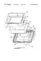
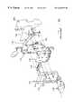
- FIG. 1is an isometric assembly view of the bottom housing of the portable pen-based computer for use with a vehicular docking station;
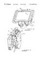
- FIG. 2is an isometric assembly view of the top housing of the portable pen-based computer for use with a vehicular docking station;
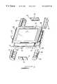
- FIG. 3is a partial assembly isometric top view of the completely-assembled, portable pen-based computer for use with a vehicular docking station;
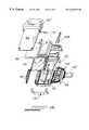
- FIG. 4Ais an isometric assembly top view of the auxiliary, independent expansion unit that is coupled to the portable pen-based computer of FIGS. 1-3 for use with a vehicular docking station;
- FIG. 4Bis an isometric assembly bottom view of the auxiliary, independent expansion unit that is coupled to the portable pen-based computer of FIGS. 1-3 for use with a vehicular docking station;
- FIG. 4Cis an isometric view of the completely-assembled, auxiliary, independent expansion unit that is coupled to the portable pen-based computer of FIGS. 1-3 for use with a vehicular docking station;
- FIG. 5Ais a front assembly view, in isometric, of the vehicular docking station for the combined computer-expansion unit of the invention
- FIG. 5Bis a rear assembly view, in isometric, of the vehicular docking station for the combined computer-expansion unit of the invention.
- FIG. 6is a front, isometric view of the assembled, vehicular docking station of FIG. 5;
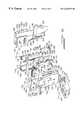
- FIG. 7is an isometric assembly view showing the three main components of the portable pen-based computer, the pen-based computer, the expansion unit, and the docking station to which the combined computer-expansion unit is coupled for use in a vehicle;
- FIG. 8is a top isometric view of the coupled state of the three main components of the portable pen-based computer of. the invention of FIG. 7;
- FIG. 9is a side isometric view of the coupled state of the three main components of the portable pen-based computer of the invention of FIG. 7 .
- the portable, pen-based computer tablet 10 of the inventionfor use with a vehicular docking station, described hereinbelow.
- the portable, pen-based computer tablet 10 of the inventionhas a rear housing-portion 10 ′ shown in FIG. 1, and a front housing-portion 10 ′′ shown in FIG. 2, both preferably made of aluminum, or magnesium, in order to provide ruggedness, excellent shielding of electrical transmissions, and for serving as an excellent heat sink to dissipate heat from the core electronics.
- the rear housing 10 ′has a main cover, mounting portion 12 which is sectioned into a number of compartments on the interior face thereof that faces toward the front housing of FIG. 2 .
- the first compartmentis a battery-mounting compartment 14 for battery pack 16 , which battery-mounting compartment 14 has a sheet-metal cover 14 ′ that locks the battery pack in place via screws, whereby the battery pack is prevented from having movement.
- a removable access cover 14 ′′seals the compartment by means of an O-ring, for preventing dust, moisture, and dirt from entering therein.
- the second compartment of the main cover, mounting portion 12is the cutout, docking-port compartment, or cavity 16 , which houses therein a 240-pin docking connector 18 , which cavity 16 projects rearwardly from the rear wall of the housing 12 .
- the docking connector 18is preferably an AMP 240-pin, self-wiping connector, which permits PCI bus and AT bus signaling to be passed from the main logic board out to the intermediate, auxiliary expansion unit or to the docking station.
- the docking connector 18protrudes rearwardly out from the cavity 16 , so that the 240-pin connector projects rearwardly and out from the rear, or exterior, surface of the main cover, mounting portion 12 .
- the docking connector 18mates with a mating connector provided on the intermediate, auxiliary expansion unit discussed hereinbelow with reference to FIGS. 4A-4C, or, alternatively, may mate directly to the mating connector provided on the vehicular docking station discussed hereinbelow with reference to FIGS. 8 and 9.
- the docking connector 18also faces in a vertically-downward direction, such that a mating connector on either the intermediate, auxiliary expansion unit or on the vehicular docking station is mated to it by pushing up the unit having the mating connector into the docking connector 18 .
- the docking connector 18projects rearwardly of the rear wall of the rear housing 10 ′ and downwardly.
- the docking connector 18is sealed, which provides additional sealing to prevent water, dust and dirt from entering into the housing via the cavity 16 .
- the docking connector 18is provided with two guide pins 18 ′ which assist the user in guiding the mating connector on the intermediate, auxiliary expansion unit or on the docking station into the docking connector 18 , the mating connectors having corresponding through-holes for receiving these guide pins 18 ′.
- the rearwardly-projecting cavity 16also acts a guide to the upward insertion of the mating connector. Once mated, gravity further aids in the positive connection of the vertically-oriented, mating connectors; thus, this vertical coupling of connectors provides an easy yet strong connection not readily broken by accident.
- the back wall of the cavity 16is curved, in order to aid in the above-mentioned guiding function provided thereby.
- the fact that the cavity 16 is recessed into the rear housing 12provides protection to the docking connector 16 in that the docking connector cannot be bent out of position, since the cavity overlaps the connector like a visor or hood. Since the cavity itself is shaped to provide a guide to the mating connector, prevention of the bending of the connector-pins during mating is substantially achieved.
- the docking connectoris on the rear of the housing 12 , and, therefore, on the rear of the computer 10 , the computer 10 may be docked to either the intermediate, auxiliary expansion unit or the docking station while still using the computer, without the need of having to stop work or shut down the computer, as is the case in the prior-art devices.
- the docking connector 18is mounted within the cavity 16 via one-piece, sheet-metal mounting plate 20 having holes 20 ′ that cooperate with holes 20 ′′ associated with the cavity 16 .
- a flexible cable 22Connected to the docking connector 18 is a flexible cable 22 , which has at one end thereof connector-portion 22 ′ that connects to the main logic board, described hereinbelow.
- the rear housingalso mounts the main logic board 24 which provides the core electronics that run the portable, pen-based computer 10 .
- the main logic board componentsare conventional, and include processor, RAM, run-time clock, I/O signaling and BIOS chipset, and the like.
- the main logic board 24is mounted to the rear housing-portion 10 ′ by screws passing through holes 24 ′ in the main logic board 24 and into posts 26 formed in the interior-facing surface of the main cover, mounting portion 12 .
- the main logic board 24fills most of the interior space of the rear housing-portion 10 ′ not taken up by the battery compartment 14 .
- Mounted on the underside of the main logic board 24is a hard drive 28 , such mounting allowing for better shock absorption and for a direct connection to the circuitry on the main logic board.
- the hard driveis able to withstand 125 G of shock while operating and 350 G of shock when not operating.
- the hard driveis supported with shock-absorbing/dispersing foam (not shown) that is seated between the interior-facing wall of the rear housing-portion 10 ′ and the hard drive itself.
- the final compartment of the rear housing-portion 10 ′is switch-compartment 30 for an on-off switch, reset switch, and DC power plug.
- the rear housing-portion 10 ′is also provided with two guide-pin holes which receive and guide therein guide-pins provided on the docking station, as set forth in greater detail hereinbelow, whereby the portable, pen-based computer tablet 10 may be easily and surely connected to the docking station.
- the front housing-portion or section 10 ′′is shown.
- the front housing-portion 10 ′′which is secured to the rear housing-portion 10 ′ by means of brackets shown in FIG. 3, and described hereinbelow, and is made up of a main mounting section or plate 36 having a rearwardly-facing, interior surface 36 ′ to which are mounted other component-parts of the computer 10 .
- the front housing-portion or section 10 ′′is also preferably made of aluminum or magnesium to ensure ruggedness, and to provide excellent shielding of electrical transmissions, and for serving as an excellent heat sink to dissipate heat from the core electronics.
- a seal 40Perimetrically surrounding the interior surface 36 of the main mounting section or plate 36 is a seal 40 that is sandwiched between the front and rear housings 10 ′, 10 ′′, which provides EMI shielding as well as protection from water, dust and dirt.
- Attached to the front face of the front housing-portion 10 ′′is a conventional membrane switch-assembly 42 , which is a user-interface component that provides status-indicators to the computer-operator.
- This membrane switch-assembly 42includes LED indicators for Power ON, hard-drive activity, docking status, brightness and contrast controls for the LCD screen,as well as an automatic setting for screen brightness depending upon ambient lighting conditions.
- the membrane switch-assembly 42is secured in place the front of the housing-portion 10 ′′ via adhesive.
- a right-angled flexible cable 42 ′is integrated into the membrane switch-assembly 42 and runs through a small opening or slit formed in the face of the front housing, which cable 42 ′ connects to the main logic board 24 on the rear housing, as described above.
- a glass/electrostatic digitizer 44is also associated with the front housing.
- the electrostatic digitizeris embedded into the glass itself to thus be formed integrally with the glass.
- the glass/electrostatic digitizer combination 44serves as the main area for the pen-stylus input.
- the electrostatic digitizeris a separate component below the LCD panel below the glass-layer or screen, with the glass-layer sitting on the LCD panel, thus placing the digitizer two layers below the user-interface, or glass- layer.
- the electrostatic digitizer 44is a secured to the undersurface of the front housing by means of digitizer tape 44 ′, which is a double-sided tape that creates a positive seal against water, dust and dirt.
- digitizer tape 44 ′is a double-sided tape that creates a positive seal against water, dust and dirt.
- a conventional LCD screen 50which is secured to the peripheral undersurface of the electrostatic digitizer 44 by means of a double-sided tape, that permits the LCF screen to flex slightly in order to absorb shock and vibrations,and that allows the LC screen to be easily and readily removed when required to replace the digitizer or when upgrading the display panel.
- the LCD panelis firmly held in place to the front housing by means of bracket 52 , which is secured to the front housing 10 ′′ by eight a series of screws passing through holes 54 on the top and bottom of the bracket and through holes 54 ′ on the top and bottom of the main mounting section or plate 36 .
- FIG. 3there is shown the assembly of the portable, pen-based computer tablet 10 , with the front housing 10 ′′ being secured to the rear housing 10 ′ by means of a plurality of grips or mounting brackets.
- Each mounting bracket or gripslides along the abutting, corresponding lateral edges of the front and rear housings and is guided therein by means of a channel 68 formed in each upper edge-surface of the front housing and channel 68 ′ formed in each lower edge-surface of the rear housing.
- the front and rear housingstherefore, are secured together without the use of screws, and are easily removed from one another, while being securely and sealingly fastened together when assembled.
- the bracketsserves not only to create the final seal by compressing the seal, or gasket, 40 that is sandwiched between the front and rear housings, as shown and described above with reference to FIG. 2, but also serve as shock-absorbers if the computer 10 is dropped.
- each grip 60 - 66has a slight convex, outer curvature, so that, if the computer should be dropped, it will land on this convex-shaped part, whereby the impact will be experienced on a narrow line along the convex part, and not on an entire flat surface, thus spreading the shock of the impact throughout the remainder of the grip.
- every direction of the computer 10has a portion of a shock-absorbing grip projecting beyond a corresponding edge-surface of the front and rear housings, whereby-when the computer is dropped, only the projecting portion of a grip will contact the floor or ground during impact.
- the grips 62 and 64are also replaceable and interchangeable one with another.
- the grip 66is provided with a cutout 66 ′ for allowing access to the switches provided in the rear housing, as described above with reference to FIG. 1, and, therefore, is not interchangeable with another one.
- upper and lower rubber pads 70 , 72are also provided, with interior sheet-metal slides, as in the construction of the grips. These pads are located along the center of the respective upper and lower edge-surfaces of the front and rear housings, also serve to secure the two housing portions 10 ′, 10 ′′together.
- Each pad 70 , 72also has a recess or concave cutout 70 ′, 72 ′, along the width of its exterior surface, which serve as guides for docking the computer to a docking station, as discussed in detail hereinbelow with reference to FIG. 8, which docking station has a mating, elongated convex surface that is received in cutout or groove 72 ′ during connection of the computer 10 to the vehicular docking station.
- This featureis important sine in docking the computer to its vehicular docking station (FIG. 8 ), such is performed in a blind manner, since the pin connector is located on the rear surface of the rear housing portion, or on the rear surface of the auxiliary expansion unit, as described hereinbelow with reference to FIGS. 4A-4C.
- Using the guide slot 72 ′allows for an easy and safe attachment of the computer to the vehicular docking station.
- auxiliary expansion unit 80 of the inventionThe primary function of this unit is to provide the capability of coupling auxiliary devices to the main pen computer tablet 10 , such as standard serial and parallel ports, keyboard port, mouse port, floppy-disk drive connector, and a universal serial bus port, all of which allow for the connection of auxiliary, or peripheral, equipment, such as a printer, modem, keyboard, and the like.
- the main function of this unitis to provide the capability of adding and/or changing the wireless and GPS systems in the field, without the need of sending the entire computer system back to the manufacturer, as is the case in prior-art systems, and also to serve as a handle for the main pen computer tablet 10 .
- the auxiliary expansion unit 80has a front housing section 82 and a main rear housing section 84 both made of magnesium.
- the front housing section 82acts a cover for the housing section 84 , and mounts a 240-pin connector 82 ′ for the mating connector 18 of the main pen tablet computer 10 of FIGS. 1-3 extending from the rear thereof. Since the connector 18 faces downwardly, or is accessed from below, the connector 82 ′ faces upwardly or is accessed from above, thereby allowing the mating connection of the two connectors.
- the front housing or cover 82is secured to the main housing section 84 via a plurality of screws passing through holes formed by hollow studs 84 in the front housing section 82 , which screws also are received in similar holes in the main rear housing section 84 .
- auxiliary expansion unit 80In between the two housing sections are mounted the operational parts of the auxiliary expansion unit 80 as described hereinbelow.
- Projecting from the rear surface of the main rear housing section 84is a recessed cutout 88 which receives another 240-pin connector 88 ′.
- the recessed cutout 88is similar to the recess 16 formed in the rear housing of the pen tablet computer 10 (FIG. 1) for the 240-pin connector 18 .
- Either of the 240-pin connectors 18 or 88 ′is capable of being coupled to a mating connector formed in the front of the associated vehicular docking station, discussed hereinbelow.
- the principal element mounted in the auxiliary expansion unit 80is an easily removable and replaceable, conventional radio module 90 , such as that manufactured by RIM Manufacturing Co.
- This radio moduleis one of the following types: RAM mobile Data, ARDIS, Global Positioning System (GPS), Cellular Digital Packet Data (CDPD), Spread Spectrum (2.4 GHz.), or Personal Communication Services (PCS) on narrow band channels.
- GPSGlobal Positioning System
- CDPDCellular Digital Packet Data
- PCSPersonal Communication Services
- the radio module 90is seated against the interior, or inwardly-facing, surface 83 of the front housing section 82 , and is positioned against a portion thereof that is below the section 83 ′ which mates with circular portion 89 of the main rear housing section 84 from which extends the recessed cutout 88 for the connector 88 ′, as best seen in FIG. 4 A.
- a conventional printed circuit boardPositioned between the radio module 90 and the main rear housing 84 is a conventional printed circuit board (PCB) that houses the core electronics 92 .
- PCBprinted circuit board
- the PCB 92mounts a number of ports 92 ′, such as a RS232 , 9-pin serial port, a 25-pin parallel port, a 6-pin keyboard port, a 5-pin mouse port, a floppy-disk drive connector, and a Universal serial bus port. These ports allow are preferably located on the sides of the PCB 92 , and allow for communication with peripherals, such as printers, modems, keyboard, etc.
- the PCB 92extends PCI BUS, and also runs Super I/O for serial and parallel controllers. Also, on the top of the PCB 92 there may be provided a PCMCIA card-cage that allows for system-expansion by adding a PCMCIA card, such an integrated radio module different from module 90 .
- the PCMCIA card-cageis provided via a top rubber cover 94 , which also provides shock-absorption from knocks and drops of the unit onto the top thereof.
- the rubber cover 94also has a hinged door 94 ′ which allows access to the PCMCIA card-cage, and also provides a seal to moisture, dirt and dust.
- the PCMCIA card-cageis preferably accessible from the top of the unit so that any device installed and connected thereto may be easily and quickly disconnected and removed from the unit.
- the main rear housing 84also has slots 98 on either lateral side thereof which allow access to the above-mentioned ports of the PCB 92 . These slots 98 are closed off by hinged, port-cover doors 99 , 99 ′, which also provide a seal therefor.
- the bottom of the unitis provided with a bottom, protective rubber foot pad 100 which serves two main functions: It has a 5% grade to its bottom surface 100 ′ which allows the auxiliary expansion unit 80 and attached pen-based computer tablet 10 to be self-standing on a flat surface; and it provides shock-absorption when the unit is bumped or dropped on the bottom portion thereof. Since the radio module 90 is mounted in the auxiliary expansion unit 80 , it is extremely important to provide this shock-absorption.
- a cap 102In order to protect the docking connector recess 88 and the connector 88 ′ therein when the unit is not in use, there is also provided a cap 102 .
- the cap 102has a flexible mounting arm 102 ′ that is received in a mounting slot 104 for removably securing the cap to the main rear housing 84 .
- Located next to the PCMCIA card-cage on the top of the unitis a 1 ⁇ 4 wave or 1 ⁇ 2 wave radio antenna 106 for the radio used.
- the antenna 106extends through a hole 106 ′ formed in the top cover 94 .
- a flexible cable assembly 110is provided which connects the PCB 92 to the main pen-tablet computer 10 .
- the flexible cable assembly 110is actually made up of two cables: A first for passing PCT and AT bus signals from the main pen-based computer 10 via the 240-pin connector 88 ′; and a second for passing these same signals from the PCB 92 to the vehicular docking station, described hereinbelow, via the 240-pin connector 82 ′.
- These cablesare the same as that of the main computer 10 , and are AMP connectors.
- the vehicular docking station 120is capable of coupling directly to either the pen-based computer tablet 10 by itself, or to the auxiliary unit 80 when it is coupled to the pen-based computer tablet 10 .
- the vehicular docking station 120has a front mounting bracket 122 that is U-shaped in cross section, and defining a front surface-plate 122 ′ with rearwardly-projecting side plates 124 , 124 ′.
- the front platealso mounts a hood or shield 130 that is positioned above the connector 128 when projecting through opening 126 , which hood protects the connector from dust, dirt, water, and the like. This protection is important, since the connector 128 opens, or faces, upwardly, which means that dust and dirt or water would easily fall therein if not protected or covered over by the hood 130 .
- the hood 130is secured to the front surface-plate 122 ′ via screws passing through holes 122 ′′ in the front surface-plate. Also projecting from the front surface-plate 122 ′, from the upper surface thereof, is a pair of guide-pins 132 for use in guiding the pen-tablet computer 10 , or the combined computer/auxiliary unit, to the docking station, and are received in guide-holes 32 formed in the back of the auxiliary unit 80 (see FIG. 4 C), or similar ones on the back of the pen-tablet 10 .
- These guide-pins 132provide positive reinforcement for docking between the pad and the docking station, and are coated with rubber , so that they do not mar the back of a unit.
- the side plate 122is provided with an elongated cutout or slot 134 through and in which projects and slides a clamping lever-arm 136 , which lever-arm is used for clamping and unclamping the pen-tablet or combination pen-tablet and auxiliary unit to and from the docking station.
- the lever-arm 136is pivotally mounted within the volume between the two side plates 124 , 124 ′ in the manner described hereinbelow.
- the slot 134has a detent 134 ′ that divides the slot into an upper section and a lower section.
- the detent 134 ′prevents any accidental movement of the lever-arm from this lower position, whereby accidental unlocking of the pen-tablet computer to the docking station is prevented.
- a base-pad 140mounted to the bottom edge-surface of the front surface-plate is a base-pad 140 , which has a plastic upper surface on a metal base.
- This upper, plastic surfaceis provided with a convex-shaped runner or guide 140 ′ for mating with cutout or groove 72 ′ formed in the bottom-edge of the housing of the pen-tablet 10 (FIG. 3 ), so that, during connection of the computer 10 , with or without attached auxiliary unit, to the vehicular docking station, one may feel the positive mating therebetween to ensure proper positioning.
- the base pad 140is contoured to be rounded along its edges in order to allow one to rest his foot thereon, since the docking station is mounted to a pedestal extending from the floor of a vehicle.
- the base padis also capable of housing a key-lock assembly that prevents removal of the pen-tablet computer until unlocked.
- the base padis secured to the front surface-plate by means of a yoke 142 projecting forwardly from the bottom surface of the front surface-plate 122 ′, which yoke has a downwardly-projecting connecting plate 142 ′ with hole 143 .
- the base pad 140has a pair of rearwardly-projecting side walls 141 that are spaced a distance apart that allows them to overlap the legs of the yoke 142 when the base pad is assembled to the mounting plate 122 .
- the base pad 140also has a rearwardly-projecting connecting arm 144 medially of the two side plates 141 , from the end of which projects upwardly an upright arm 144 ′ having a hole 145 formed therein that corresponds to the hole 143 of the yoke 142 .
- the rearwardly-projecting connecting arm 144is preferably made of two, spaced-apart, parallel legs, so as define a space therebetween, through which space may pass a screw or bolt that fastens the yoke 142 to the upright arm 144 ′ via the holes 143 , 145 .
- a transverse, upwardly-projecting lip 147 on the upper surface of the base pad 140abuts against the lower portion of the front surface-plate 122 ′ when the base pad is attached to the front mounting plate 122 , as can be seen in FIG. 6 .
- the first partis a sliding, docking-connector, mounting plate 150 .
- a conventional, floating, 240-pin docking connector 128is secured to the upper edge-surface 150 ′ of the mounting plate 150 .
- this connector 128opens or is connectable from above, for mating with the conventional, mating, 240-pin connectors on the pen-tablet computer or auxiliary unit 80 , whose connectors open or are connectable from below.
- the mounting plate 150slides is mounted for sliding movement, as described hereinbelow, such that it slides upwardly when the level arm 136 is pulled downwardly, for positioning the connector 128 in the downwardly-facing mating connector of the pen-tablet computer or auxiliary unit 80 .
- the lever armis slide up, whereby the mounting plate 150 is moved downwardly to move the connector 128 away from its mating connector.
- the connector 128projects outwardly through the opening, or cutout, 126 formed in the front surface-plate 122 ′, as can bee seen in FIG. 6 .
- the sliding plate 150Mounted to the lower edge of the sliding plate 150 is a lower pair of L-shaped brackets 156 , each having a vertical leg-section 156 ′ and a horizontal leg-section 156 ′′.
- the vertical leg-section 156 ′is provided with a hole 159 and a mounting pin 158 ′.
- the sliding plate 150has a pair of downwardly projecting mounting ears 158 each having a lower projecting pin 161 that is received in a hole 159 aligned therewith in the vertical leg-section 156 ′ for mounting the bracket 156 to the plate 150 .
- Each earalso has an upper hole 161 ′ for the purpose to be described below.
- the sliding plate 150also has holes 160 for receiving the mounting pins 158 ′ therethrough.
- each bracket 156is also provided with a mounting pin 166 .
- These mounting pinsare received in guide-holes 33 formed in the bottom of the pen-tablet computer's housing, as seen in FIG. 3, which also serve the purpose of clamping the pen-tablet computer to the docking station when the lever arm 136 is slid downwardly, as described hereinbelow.
- the brackets 156may be fastened to the sliding plate 150 in one of two ways, where in the first position shown in FIG. 6, the brackets 156 mount the pen-tablet computer to the docking station without the auxiliary unit 80 attached. In this case, the shorter horizontal legs 156 ′′ are used as shown in FIG.
- each pin 166is received in an upper hole 161 ′′ of a mounting ear 158 , with a pin 161 of an ear 158 being received in a hole 157 of a leg-section 156 ′′.
- the pins 158 ′ of the leg-sections 156 ′serve as the mounting pins for reception in the holes 33 of the pen-tablet computer 10 .
- the vehicular docking station 120also has a second sliding plate which is mounted to slide in the opposite direction as that of the first sliding plate 150 ; that is, when the locking lever arm 136 is slid downwardly, the first sliding plate 150 is slid up-wardly to lock the 240-pin connector 128 to the mating connector of the pen-tablet computer 10 or auxiliary unit 80 , while this second sliding plate is slid downwardly along with the locking lever arm 136 .
- This second sliding plate 170is used to firmly clamp the pen-tablet computer with or without the auxiliary unit 80 to the docking station by means of clamping arms 172 , 174 .
- Each clamping arm 172 , 174is similar to the brackets 156 on the lower edge of the first sliding plate 150 , as described above in detail.
- Each clamping arm 172 , 174has a vertical leg section 172 ′, 174 ′ and a horizontal leg section 172 ′′, 174 ′′ in which each of which is formed a hole 176 and a projecting bead or pin 178 .
- Each vertical leg sectionalso has an upper hole 180 and a lower protruding bead or pin 182 .
- the upper edge-surface of the second sliding plate 170has a pair of upwardly-projecting, spaced-apart mounting ears 184 each having a lower hole 184 ′ and an upper inwardly-projecting bead or pin 186 .
- clamping arms 172 , 174are the same as that of the lower brackets 156 of the first sliding plate.
- the clamping armsare mounted as shown in FIG. 6, with the bead or pins 186 received in holes 180 of the vertical leg sections, and with each lower bead or pin 182 being received in a respective slot 171 formed in the lateral side surfaces of the second sliding plate.
- the downwardly-projecting bead or pins, or tabs, 178are received in the guide-holes 31 ′ in the upper edge-surface of the pen-tablet computer's housing (see FIG. 9 ).
- the second plateis slid down via the locking arm 136 , whereby the pen-tablet computer is locked to the docking station via the entry of the tabs 178 into the holes 31 ′.
- the clamping arms 172 , 174are inverted, whereby the horizontal leg sections now become the vertical and the vertical leg sections now become the horizontal. In this case, as can be seen in FIG.
- the second sliding plate 170also has a rectangular cutout 190 through which passes a cable-connector described hereinbelow.
- the two sliding plates 150 , 170are mounted for vertical, sliding motion by means of vertical slots 186 in plate 160 and vertical slots 188 in the plate 170 , with tie-rods 189 passing through respective pairs of vertical slots 186 , 188 for securing the plates to the front mounting bracket 122 .
- Washer or spacersspace the two vertically-sliding plates apart.
- a screw 139 ′′passes through a slot 190 in the upper portion of the first sliding plate and is received in hole 139 of the second sliding plate, whereby the two sliding plates are kept spaced apart from each other yet have relative vertical sliding movement.
- the PCB 191houses the core electronics of the docking station. It is similar to the PCB of the auxiliary unit 80 , but does not have native I/O connectors mounted to it. Rather, these I/O connectors are located in a break-out box (not shown) which is capable of being mounted anywhere in the vehicle.
- the break-out boxwill have the following I/O ports: three RS-232, 9-pin connectors; one DB25 parallel connector; one keyboard, 6-pin mini-din connector; one mouse, 6-pin connector; one universal serial BUS connector; one VGA , 15-pin connector; one floppy disk drive connector; and one SCSI connector.
- the PCB 191pass all of the signals necessary for coupling the ports to the pen tablet computer or auxiliary unit 80 .
- a Samtec connector 193provides the interface between the flex-cable assembly and the PCB 191 for connection of the PCB 191 to the other main control units of the pen-tablet computer 10 and auxiliary unit 80 .
- the connector 193with attached cable, are received through the cutout 190 of the second sliding plate 170 , as discussed above.
- the PCB 191is mounted to the assembly by means of screws 195 passing the upper holes in the mounting bracket 122 and through upper corner holes 195 ′ formed in the upper portion of the PCB 191 , which screws pass between the upright ears 184 of the second sliding plate.
- the locking lever arm 136mounted rearwardly of the two sliding plates 150 , 170 and the PCB 191 is the locking lever arm 136 , that is fabricated from sheet metal with a coating of rubber.
- the lever armhas a mounting base-portion 136 ′ having a hole 137 through which passes pivot pin 136 ′′.
- the pivot pin 136 ′′passes through center slot 187 in the first sliding plate 150 , through center slot 187 ′ in the second sliding plate, and through the hole 137 .
- a circular disk or spacer 192having approximately the same diameter as the mounting portion 136 ′ having a central hole 192 ′ also through which passes the pivot pin 136 ′′ spaces the lever arm from the second sliding plate and PCB 191 .
- the two sliding plates 150 , 170are slid in opposite, vertical directions; the first sliding plate 150 is slid upwardly when the lever arm is slid downwardly, in order to raise the floating, 240-pin connector for mating with the similar connector on the pen-tablet computer or auxiliary unit 80 .
- the second sliding plate 170is also slid vertically downwardly in order to lower the clamping arms 172 , 174 into the vertically-aligned holes 31 ′ of the pen-tablet computer, whereby the pen-tablet computer is locked securely in place to the docking station.
- This opposite, vertical motion of the two sliding platesis achieved via connecting links 200 , 202 .
- the first connecting link 202has a lower transverse end 202 ′ which is received in a hole 204 of rearwardly-projecting, lower, medially-located, L-shaped bracket 206 which has a width great enough such that the upright, vertical section of the bracket 206 is located rearwardly of the lever arm 136 .
- the transverse end 202 ′projects rearwardly for reception in the hole 204 .
- the connecting link 202is received interiorly in the L-shaped bracket 206 , with the transverse end 202 ′ turning inwardly for reception in the hole 204 .
- the upper end 203 of the first connecting link 202is connected to the mounting base-portion 136 ′ on the rearwardly-facing surface thereof, and on the lateral side of the pivot hole 137 thereof opposite to that from which extends the lever arm proper.
- the upper end 203has a pin or tab that is received in a receiving hole formed in the mounting base-portion 136 ′, as can be seen in FIG. 5 A.
- the end-pins 202 ′ and 203are capable of rotational movement in their respective receiving holes in order to accommodate the relative movement between the lever arm 136 and the first sliding plate 150 .
- the second sliding plate 170receives conjoint vertical motion with the lever arm 136 by means of the second connecting rod or link 200 that extends along the front surface-face of the lever arm 136 .
- the second connecting link 200has a lower transverse end terminating in a pin 210 that is received in a hole formed in the front surface of the lever arm on the lateral side opposite to that which the pin 203 is connected, whereby the same vertical motion is imparted to the second sliding plate 170 as that of the lever arm 136 .
- the second connecting linkhas an upper transverse end terminating in a forwardly-facing connecting pin 212 that is screwed, or otherwise secured, to the screw 139 ′′ passing through the slot 190 in the first sliding plate and through the hole 139 in the second sliding plate. All of the transverse ends of the connecting links 200 , 202 may be mounted to their respective holes via screws, or the like. It is noted that the vertical slot 190 in the first sliding plate allows for the screw 139 ′′ adequate freedom of vertical movement or lost motion, so that the two sliding plates are each free for its respective, independent, vertical, sliding movement.
- the docking stationis closed off from the rear by a rear backing plate 220 , which has a pair of wing plates 222 having holes 224 for matching holes 226 in the side plates 124 , 124 ′ of the front U-shaped mounting bracket 122 , whereby screws 230 passing through these holes fasten the rear backing plate 220 to the front bracket 122 .
- the upper portion of each wing plate 22is provided with a channel-guide 232 which receives a transverse location-pin 236 provided in each side plate 124 , 124 ′ of the front U-shaped bracket 122 .
- FIGS. 7-9show the assembled pen-tablet computer 10 , auxiliary unit 80 mounted to the docking station. It is t o be noted that the docking station is mounted to the top of a pedestal in the vehicle, which pedestal is well-known and used by other, prior-art systems.
Landscapes
- Engineering & Computer Science (AREA)
- Theoretical Computer Science (AREA)
- Computer Hardware Design (AREA)
- General Engineering & Computer Science (AREA)
- Human Computer Interaction (AREA)
- Physics & Mathematics (AREA)
- General Physics & Mathematics (AREA)
- Mechanical Engineering (AREA)
- Calculators And Similar Devices (AREA)
- Casings For Electric Apparatus (AREA)
Abstract
Description
Claims (17)
Priority Applications (2)
| Application Number | Priority Date | Filing Date | Title |
|---|---|---|---|
| US09/200,805US6426872B1 (en) | 1997-06-19 | 1998-11-27 | Portable pen-based computer with vehicular docking station |
| US10/046,604US6504710B2 (en) | 1998-11-27 | 2002-01-16 | Method of interconnecting of a hand-held auxiliary unit, a portable computer and a peripheral device |
Applications Claiming Priority (2)
| Application Number | Priority Date | Filing Date | Title |
|---|---|---|---|
| US08/878,758US6101087A (en) | 1997-06-19 | 1997-06-19 | Portable pen-based computer and auxiliary unit for use with a vehicular docking station |
| US09/200,805US6426872B1 (en) | 1997-06-19 | 1998-11-27 | Portable pen-based computer with vehicular docking station |
Related Parent Applications (1)
| Application Number | Title | Priority Date | Filing Date |
|---|---|---|---|
| US08/878,758DivisionUS6101087A (en) | 1997-06-19 | 1997-06-19 | Portable pen-based computer and auxiliary unit for use with a vehicular docking station |
Related Child Applications (1)
| Application Number | Title | Priority Date | Filing Date |
|---|---|---|---|
| US10/046,604ContinuationUS6504710B2 (en) | 1998-11-27 | 2002-01-16 | Method of interconnecting of a hand-held auxiliary unit, a portable computer and a peripheral device |
Publications (1)
| Publication Number | Publication Date |
|---|---|
| US6426872B1true US6426872B1 (en) | 2002-07-30 |
Family
ID=25372775
Family Applications (2)
| Application Number | Title | Priority Date | Filing Date |
|---|---|---|---|
| US08/878,758Expired - LifetimeUS6101087A (en) | 1997-06-19 | 1997-06-19 | Portable pen-based computer and auxiliary unit for use with a vehicular docking station |
| US09/200,805Expired - LifetimeUS6426872B1 (en) | 1997-06-19 | 1998-11-27 | Portable pen-based computer with vehicular docking station |
Family Applications Before (1)
| Application Number | Title | Priority Date | Filing Date |
|---|---|---|---|
| US08/878,758Expired - LifetimeUS6101087A (en) | 1997-06-19 | 1997-06-19 | Portable pen-based computer and auxiliary unit for use with a vehicular docking station |
Country Status (1)
| Country | Link |
|---|---|
| US (2) | US6101087A (en) |
Cited By (53)
| Publication number | Priority date | Publication date | Assignee | Title |
|---|---|---|---|---|
| US20020125860A1 (en)* | 2001-02-14 | 2002-09-12 | Ernst Schworm | Mains-independent power supply unit |
| US20020186177A1 (en)* | 2001-06-12 | 2002-12-12 | Hong Peter S. | Battery |
| US20030222848A1 (en)* | 2002-05-31 | 2003-12-04 | Solomon Mark C. | System and method of switching viewing orientations of a display |
| US20040030878A1 (en)* | 2002-08-08 | 2004-02-12 | Hunt Peter D. | Rapid access to data on a powered down personal computer |
| US20040039862A1 (en)* | 2002-08-08 | 2004-02-26 | Hunt Peter D. | System and method of switching between multiple viewing modes in a multi-head computer system |
| US20040085738A1 (en)* | 2002-11-06 | 2004-05-06 | Walkabout Computers, Inc. | Secure hinge mechanism for portable computer |
| US20050047079A1 (en)* | 2003-08-26 | 2005-03-03 | Gasbarro Henry Frank | Computer system with configurable docking station |
| US20050111181A1 (en)* | 2003-11-24 | 2005-05-26 | Dell Products L.P. | Vertically docking an information handling system to a media slice |
| US20050128693A1 (en)* | 2003-12-15 | 2005-06-16 | Katsunori Itoh | Electronic apparatus |
| US20070076362A1 (en)* | 2005-09-30 | 2007-04-05 | Isaac Lagnado | Computer device having multi-function handle |
| US7209124B2 (en)* | 2002-08-08 | 2007-04-24 | Hewlett-Packard Development Company, L.P. | Multiple-position docking station for a tablet personal computer |
| US20080112118A1 (en)* | 2006-11-15 | 2008-05-15 | Hiroshi Osaka | Function expanding method for small-sized display device |
| US20080304688A1 (en)* | 1999-04-07 | 2008-12-11 | Rajendra Kumar | Docking display station with docking port for retaining a hands-free headset therein |
| US20090202112A1 (en)* | 2008-02-12 | 2009-08-13 | Nielsen Steven E | Searchable electronic records of underground facility locate marking operations |
| US20090201022A1 (en)* | 2008-02-11 | 2009-08-13 | Ralph Oppelt | Control apparatus for a magnetic resonance imaging antenna arrangement |
| US20090204625A1 (en)* | 2008-02-12 | 2009-08-13 | Curtis Chambers | Electronic manifest of underground facility locate operation |
| US20090241046A1 (en)* | 2008-03-18 | 2009-09-24 | Steven Nielsen | Virtual white lines for delimiting planned excavation sites |
| US20090238417A1 (en)* | 2008-03-18 | 2009-09-24 | Nielsen Steven E | Virtual white lines for indicating planned excavation sites on electronic images |
| US20090278739A1 (en)* | 2008-03-14 | 2009-11-12 | Itt Manufacturing Enterprises, Inc. | GPS Signal Data Converter for Providing GPS Signals to a Plurality of Connection Ports |
| US20100201690A1 (en)* | 2009-02-11 | 2010-08-12 | Certusview Technologies, Llc | Virtual white lines (vwl) application for indicating a planned excavation or locate path |
| US20100201706A1 (en)* | 2009-02-11 | 2010-08-12 | Certusview Technologies, Llc | Virtual white lines (vwl) for delimiting planned excavation sites of staged excavation projects |
| US20120106068A1 (en)* | 2010-11-03 | 2012-05-03 | Compal Electronics, Inc. | Portable electronic device |
| US20120120581A1 (en)* | 2009-09-29 | 2012-05-17 | Edgar Diego Haren | Docking device mounting systems and methods |
| US20120170203A1 (en)* | 2011-01-03 | 2012-07-05 | Ems Technologies, Inc. | Quick Mount System for Computer Terminal |
| US8311765B2 (en) | 2009-08-11 | 2012-11-13 | Certusview Technologies, Llc | Locating equipment communicatively coupled to or equipped with a mobile/portable device |
| US8361543B2 (en) | 2008-10-02 | 2013-01-29 | Certusview Technologies, Llc | Methods and apparatus for displaying an electronic rendering of a marking operation based on an electronic record of marking information |
| US8374789B2 (en) | 2007-04-04 | 2013-02-12 | Certusview Technologies, Llc | Systems and methods for using marking information to electronically display dispensing of markers by a marking system or marking tool |
| US8400155B2 (en) | 2008-10-02 | 2013-03-19 | Certusview Technologies, Llc | Methods and apparatus for displaying an electronic rendering of a locate operation based on an electronic record of locate information |
| US8407001B2 (en) | 2007-03-13 | 2013-03-26 | Certusview Technologies, Llc | Systems and methods for using location data to electronically display dispensing of markers by a marking system or marking tool |
| US8442766B2 (en) | 2008-10-02 | 2013-05-14 | Certusview Technologies, Llc | Marking apparatus having enhanced features for underground facility marking operations, and associated methods and systems |
| US8572193B2 (en) | 2009-02-10 | 2013-10-29 | Certusview Technologies, Llc | Methods, apparatus, and systems for providing an enhanced positive response in underground facility locate and marking operations |
| US8583372B2 (en) | 2009-12-07 | 2013-11-12 | Certusview Technologies, Llc | Methods, apparatus, and systems for facilitating compliance with marking specifications for dispensing marking material |
| US8620572B2 (en) | 2009-08-20 | 2013-12-31 | Certusview Technologies, Llc | Marking device with transmitter for triangulating location during locate operations |
| US8619417B1 (en)* | 2011-11-08 | 2013-12-31 | The United States Of America As Represented By The Secretary Of The Navy | Water-resistant computer docking station |
| US8620616B2 (en) | 2009-08-20 | 2013-12-31 | Certusview Technologies, Llc | Methods and apparatus for assessing marking operations based on acceleration information |
| US8626571B2 (en) | 2009-02-11 | 2014-01-07 | Certusview Technologies, Llc | Management system, and associated methods and apparatus, for dispatching tickets, receiving field information, and performing a quality assessment for underground facility locate and/or marking operations |
| US20140211388A1 (en)* | 2001-11-19 | 2014-07-31 | Otter Products, Inc. | Protective enclosure for electronic device |
| US8794579B2 (en) | 2005-06-03 | 2014-08-05 | Steelcase, Inc. | Support arm assembly |
| US8830265B2 (en) | 2009-07-07 | 2014-09-09 | Certusview Technologies, Llc | Methods, apparatus and systems for generating searchable electronic records of underground facility marking operations and assessing aspects of same |
| US8867202B2 (en) | 2011-08-23 | 2014-10-21 | L&P Property Management Company | Docking station |
| US8873233B2 (en) | 2011-10-28 | 2014-10-28 | Xplore Technologies Corp. | Vehicle dock for ruggedized tablet |
| US8902251B2 (en) | 2009-02-10 | 2014-12-02 | Certusview Technologies, Llc | Methods, apparatus and systems for generating limited access files for searchable electronic records of underground facility locate and/or marking operations |
| US8929065B2 (en) | 2011-08-23 | 2015-01-06 | L&P Property Management Company | Docking station with ruggedized case |
| US8930836B2 (en) | 2008-10-02 | 2015-01-06 | Certusview Technologies, Llc | Methods and apparatus for displaying an electronic rendering of a locate and/or marking operation using display layers |
| US9097522B2 (en) | 2009-08-20 | 2015-08-04 | Certusview Technologies, Llc | Methods and marking devices with mechanisms for indicating and/or detecting marking material color |
| US9280269B2 (en) | 2008-02-12 | 2016-03-08 | Certusview Technologies, Llc | Electronic manifest of underground facility locate marks |
| US20170210301A1 (en)* | 2015-08-17 | 2017-07-27 | Havis, Inc. | Keyboard mounting system |
| US20170320392A1 (en)* | 2014-11-19 | 2017-11-09 | Manitou Bf | Device and system for controlling functions of an industrial or all-terrain vehicle |
| USD892123S1 (en) | 2018-07-16 | 2020-08-04 | ACCO Brands Corporation | Dock for a portable electronic device |
| US10907383B2 (en) | 2017-03-01 | 2021-02-02 | ACCO Brands Corporation | Dock for a portable electronic device |
| US10917986B2 (en) | 2018-03-08 | 2021-02-09 | ACCO Brands Corporation | Dock for a portable electronic device |
| US11023247B2 (en)* | 2018-06-29 | 2021-06-01 | Intel Corporation | Processor package with optimization based on package connection type |
| US11146031B2 (en)* | 2019-04-17 | 2021-10-12 | Acer Incorporated | Expansion device |
Families Citing this family (60)
| Publication number | Priority date | Publication date | Assignee | Title |
|---|---|---|---|---|
| JP3248712B2 (en)* | 1996-11-05 | 2002-01-21 | 富士通株式会社 | Function expansion device for information processing device |
| US6424524B2 (en)* | 1998-08-21 | 2002-07-23 | Compaq Information Technologies Group, L.P. | Wedge-shaped port replicator for portable computer |
| US6327570B1 (en)* | 1998-11-06 | 2001-12-04 | Dian Stevens | Personal business service system and method |
| US10078850B2 (en) | 1998-11-06 | 2018-09-18 | Iii Holdings 1, Llc | Personal business service system and method |
| US8494878B2 (en)* | 1998-11-06 | 2013-07-23 | Dian Stevens | Personal business service system and method |
| US20050075908A1 (en)* | 1998-11-06 | 2005-04-07 | Dian Stevens | Personal business service system and method |
| JP4013378B2 (en)* | 1998-12-18 | 2007-11-28 | 株式会社デンソー | Electronic control device and jig structure thereof |
| JP2001337743A (en)* | 2000-05-24 | 2001-12-07 | Hitachi Ltd | Information processing device |
| US6421233B1 (en)* | 2000-06-12 | 2002-07-16 | High Tech Computer Corporation | Pocket personal computer with improved battery compartment enclosing structure |
| US6282083B1 (en)* | 2000-07-28 | 2001-08-28 | Enlight Corporation | Computer mainframe and stand arrangement |
| US6942395B1 (en) | 2001-01-29 | 2005-09-13 | Jds Uniphase Corporation | Method and apparatus of pull-lever release for fiber optic modules |
| US6597567B2 (en)* | 2001-03-05 | 2003-07-22 | Toshiba America Information Systems, Inc. | Corner support members for housing system |
| US6994478B1 (en) | 2001-04-14 | 2006-02-07 | Jds Uniphase Corporation | Modules having rotatable release and removal lever |
| US6851867B2 (en) | 2001-04-14 | 2005-02-08 | Jds Uniphase Corporation | Cam-follower release mechanism for fiber optic modules with side delatching mechanisms |
| US6863448B2 (en) | 2001-04-14 | 2005-03-08 | Jds Uniphase Corporation | Method and apparatus for push button release fiber optic modules |
| US6692159B2 (en) | 2001-04-14 | 2004-02-17 | E20 Communications, Inc. | De-latching mechanisms for fiber optic modules |
| US6840680B1 (en) | 2001-04-14 | 2005-01-11 | Jds Uniphase Corporation | Retention and release mechanisms for fiber optic modules |
| US6796715B2 (en) | 2001-04-14 | 2004-09-28 | E20 Communications, Inc. | Fiber optic modules with pull-action de-latching mechanisms |
| ITMI20011145A1 (en)* | 2001-05-30 | 2002-11-30 | Antonio Bartolozzi | MULTIFUNCTIONAL CAR RADIO STRUCTURE, PARTICULARLY FOR MOTOR VEHICLES AND SIMILAR |
| US6789958B2 (en)* | 2001-08-31 | 2004-09-14 | Infineon Technologies Ag | Release mechanism for pluggable fiber optic transceiver |
| US7314384B2 (en)* | 2001-10-04 | 2008-01-01 | Finisar Corporation | Electronic modules having an integrated connector detachment mechanism |
| US6439918B1 (en)* | 2001-10-04 | 2002-08-27 | Finisar Corporation | Electronic module having an integrated latching mechanism |
| US7186134B2 (en)* | 2001-10-04 | 2007-03-06 | Finisar Corporation | Electronic modules having integrated lever-activated latching mechanisms |
| US6597577B1 (en)* | 2001-11-16 | 2003-07-22 | Hewlett-Packard Development Company, L.P. | Systems with pedestal stands for mounting components |
| US20030149822A1 (en)* | 2002-02-01 | 2003-08-07 | Bryan Scott | Method for integrating an intelligent docking station with a handheld personal computer |
| US7231481B2 (en)* | 2002-02-01 | 2007-06-12 | Bryan Scott | Intelligent docking station for a handheld personal computer |
| US20030149818A1 (en)* | 2002-02-01 | 2003-08-07 | Bryan Scott | System for integrating an intelligent docking station with a handheld personal computer |
| US6544075B1 (en)* | 2002-04-24 | 2003-04-08 | Accton Technology Corporation | Wireless adapter |
| JP3963785B2 (en)* | 2002-06-11 | 2007-08-22 | 富士通株式会社 | Information processing apparatus and printed circuit board |
| TW540286B (en)* | 2002-08-07 | 2003-07-01 | Quanta Comp Inc | Buffer device |
| US7118281B2 (en) | 2002-08-09 | 2006-10-10 | Jds Uniphase Corporation | Retention and release mechanisms for fiber optic modules |
| KR100655549B1 (en)* | 2002-08-29 | 2006-12-07 | 엘지전자 주식회사 | Portable hybrid computer |
| US20040119390A1 (en)* | 2002-12-24 | 2004-06-24 | Huang Chin Sui | Protection structure of portable electron device |
| USD486785S1 (en) | 2003-05-27 | 2004-02-17 | Sony Corporation | Combined locating system holder and battery charger |
| US7321488B2 (en)* | 2003-06-10 | 2008-01-22 | Fujitsu Limited | Printed circuit board with flap unit |
| US7274564B2 (en)* | 2003-06-23 | 2007-09-25 | Jaco, Inc. | Locking cradle for tablet computers |
| ES1055295Y (en)* | 2003-07-30 | 2004-02-16 | Proindumar Sl | SUPPORT FOR DRIVE MOTOR FOR IMAGE CARRIER ROLLERS IN RECREATIONAL MACHINES |
| US7424126B2 (en)* | 2004-05-27 | 2008-09-09 | Symbol Technologies, Inc. | Fix mounted earphone jack |
| US8229501B2 (en)* | 2004-09-09 | 2012-07-24 | Dana Innovations | Computer wall docking station |
| US20060066438A1 (en)* | 2004-09-27 | 2006-03-30 | David Altounian | Method and system for controllably and selectively securing a portable computing device to a physical holding device |
| KR100598121B1 (en)* | 2005-03-08 | 2006-07-07 | 삼성전자주식회사 | Portable display device |
| US20060278629A1 (en)* | 2005-06-08 | 2006-12-14 | Western Industries, Inc. | Electronically controlled outdoor warmer |
| US7978466B2 (en)* | 2008-02-27 | 2011-07-12 | L&P Property Management Company | Computer docking station for a vehicle |
| US8014148B2 (en)* | 2008-02-28 | 2011-09-06 | Panasonic Corporation | Electronic device |
| GB2460075B (en)* | 2008-05-15 | 2012-11-28 | Panasonic Mfg Uk Ltd | Display screen mount |
| CN101770260B (en)* | 2009-01-05 | 2012-07-25 | 联想(北京)有限公司 | Detachable-portable computing equipment |
| USD628199S1 (en)* | 2009-07-14 | 2010-11-30 | Panasonic Corporation | Display device |
| US7911779B1 (en) | 2009-09-30 | 2011-03-22 | L&P Property Management Company | Computer docking station |
| US9178976B2 (en) | 2010-11-01 | 2015-11-03 | Mitab Inc. | Apparatus and method for using a smartphone |
| WO2013050916A1 (en)* | 2011-10-02 | 2013-04-11 | Intaltech Ltd. | Portable computer vehicle dock |
| US8751710B2 (en) | 2012-05-08 | 2014-06-10 | Entegra Technologies, Inc. | Reconfigurable modular computing device |
| JP6036547B2 (en)* | 2013-05-22 | 2016-11-30 | 株式会社デンソー | Electronic control unit and protective case |
| JP6146131B2 (en)* | 2013-05-22 | 2017-06-14 | 株式会社デンソー | Electronic control unit and protective case |
| US9310840B2 (en)* | 2014-02-27 | 2016-04-12 | First Data Corporation | Systems, methods, and apparatus for docking a handheld device |
| JP6389774B2 (en)* | 2015-02-10 | 2018-09-12 | 東芝テック株式会社 | Product sales data processing device |
| MX373978B (en)* | 2015-06-15 | 2020-07-06 | Comau Spa | PORTABLE SAFETY CONTROL DEVICE FOR INDUSTRIAL MACHINES, PARTICULARLY ROBOTS. |
| US11639039B1 (en) | 2016-02-04 | 2023-05-02 | Maurice Paperi | Matching pieces and kits for repairing broken structures and related methods |
| US10061354B2 (en) | 2016-10-14 | 2018-08-28 | Gamber-Johnson Llc | Docking station for electronic device |
| US11148578B2 (en)* | 2018-03-25 | 2021-10-19 | Maurice Paperi | Universal mounting tabs and kits for automotive components |
| US10976777B2 (en) | 2019-08-15 | 2021-04-13 | Gamber-Johnson Llc | Docking station |
Citations (13)
| Publication number | Priority date | Publication date | Assignee | Title |
|---|---|---|---|---|
| US5321580A (en)* | 1990-02-09 | 1994-06-14 | Kabushiki Kaisha Toshiba | Expansion device with power cord and guide groove for expanding functions of compact electronic apparatus |
| US5323291A (en)* | 1992-10-15 | 1994-06-21 | Apple Computer, Inc. | Portable computer and docking station having an electromechanical docking/undocking mechanism and a plurality of cooperatively interacting failsafe mechanisms |
| US5347115A (en)* | 1990-01-12 | 1994-09-13 | Norand Corporation | Portable modular work station including printer and portable data collection terminal |
| US5347425A (en)* | 1992-10-15 | 1994-09-13 | Apple Computer, Inc. | Docking station for a portable computer |
| US5396399A (en)* | 1992-09-21 | 1995-03-07 | Telepad Corporation | Multi-purpose handle/prop for pen-based computer having overhanging front surface |
| US5477415A (en)* | 1993-11-12 | 1995-12-19 | Texas Instruments Incorporated | Automatic computer docking station having a motorized tray, cammed side connectors, motorized side connectors, and locking and unlocking guide pins |
| US5491609A (en)* | 1994-02-28 | 1996-02-13 | Telepad | Portable electronic platform system |
| US5535093A (en)* | 1994-06-20 | 1996-07-09 | International Business Machines Corporation | Portable computer docking device having a first rotatable connector and a second connector |
| US5579487A (en)* | 1992-10-02 | 1996-11-26 | Teletransaction, Inc. | Portable work slate computer with multiple docking positions for interchangeably receiving removable modules |
| US5619397A (en)* | 1994-09-29 | 1997-04-08 | Kabushiki Kaisha Toshiba | Electronic device system including a portable electronic device having a handwriting input device locked to an expansion station when the power switch of the portable electronic device is turned on |
| US5644471A (en)* | 1990-07-25 | 1997-07-01 | Norand Corporation | Portable dock for a portable electronic device |
| US5825617A (en)* | 1992-10-02 | 1998-10-20 | Teletransactions, Inc. | Workslate computer having modular device docking stations on horizontal and vertical side portions |
| US5826042A (en)* | 1996-08-02 | 1998-10-20 | Compaq Computer Corporation | Portable computer docking station with module connection replicator |
Family Cites Families (7)
| Publication number | Priority date | Publication date | Assignee | Title |
|---|---|---|---|---|
| US34476A (en)* | 1862-02-25 | Improvement in hose-couplings | ||
| US4345147A (en)* | 1980-11-14 | 1982-08-17 | International Telephone And Telegraph Corporation | Vehicle mounted mobile business data handling system |
| US5598487A (en)* | 1986-08-15 | 1997-01-28 | Norand Corporation | Hand-held data entry system removable signature pad |
| US4969830A (en)* | 1989-06-12 | 1990-11-13 | Grid Systems Corporation | Connection between portable computer components |
| USRE34476E (en) | 1990-05-14 | 1993-12-14 | Norwood Donald D | Hybrid information management system for handwriting and text |
| DE59109059D1 (en)* | 1991-02-22 | 1998-10-29 | Siemens Ag | Flexible automation system |
| US5552957A (en)* | 1994-09-09 | 1996-09-03 | International Business Machines Corporation | Portable computer field kit |
- 1997
- 1997-06-19USUS08/878,758patent/US6101087A/ennot_activeExpired - Lifetime
- 1998
- 1998-11-27USUS09/200,805patent/US6426872B1/ennot_activeExpired - Lifetime
Patent Citations (13)
| Publication number | Priority date | Publication date | Assignee | Title |
|---|---|---|---|---|
| US5347115A (en)* | 1990-01-12 | 1994-09-13 | Norand Corporation | Portable modular work station including printer and portable data collection terminal |
| US5321580A (en)* | 1990-02-09 | 1994-06-14 | Kabushiki Kaisha Toshiba | Expansion device with power cord and guide groove for expanding functions of compact electronic apparatus |
| US5644471A (en)* | 1990-07-25 | 1997-07-01 | Norand Corporation | Portable dock for a portable electronic device |
| US5396399A (en)* | 1992-09-21 | 1995-03-07 | Telepad Corporation | Multi-purpose handle/prop for pen-based computer having overhanging front surface |
| US5825617A (en)* | 1992-10-02 | 1998-10-20 | Teletransactions, Inc. | Workslate computer having modular device docking stations on horizontal and vertical side portions |
| US5579487A (en)* | 1992-10-02 | 1996-11-26 | Teletransaction, Inc. | Portable work slate computer with multiple docking positions for interchangeably receiving removable modules |
| US5323291A (en)* | 1992-10-15 | 1994-06-21 | Apple Computer, Inc. | Portable computer and docking station having an electromechanical docking/undocking mechanism and a plurality of cooperatively interacting failsafe mechanisms |
| US5347425A (en)* | 1992-10-15 | 1994-09-13 | Apple Computer, Inc. | Docking station for a portable computer |
| US5477415A (en)* | 1993-11-12 | 1995-12-19 | Texas Instruments Incorporated | Automatic computer docking station having a motorized tray, cammed side connectors, motorized side connectors, and locking and unlocking guide pins |
| US5491609A (en)* | 1994-02-28 | 1996-02-13 | Telepad | Portable electronic platform system |
| US5535093A (en)* | 1994-06-20 | 1996-07-09 | International Business Machines Corporation | Portable computer docking device having a first rotatable connector and a second connector |
| US5619397A (en)* | 1994-09-29 | 1997-04-08 | Kabushiki Kaisha Toshiba | Electronic device system including a portable electronic device having a handwriting input device locked to an expansion station when the power switch of the portable electronic device is turned on |
| US5826042A (en)* | 1996-08-02 | 1998-10-20 | Compaq Computer Corporation | Portable computer docking station with module connection replicator |
Cited By (148)
| Publication number | Priority date | Publication date | Assignee | Title |
|---|---|---|---|---|
| US8483755B2 (en)* | 1999-04-07 | 2013-07-09 | Khyber Technoliges, Corporation | Docking display station with docking port for retaining a hands-free headset therein |
| US20080304688A1 (en)* | 1999-04-07 | 2008-12-11 | Rajendra Kumar | Docking display station with docking port for retaining a hands-free headset therein |
| US20020125860A1 (en)* | 2001-02-14 | 2002-09-12 | Ernst Schworm | Mains-independent power supply unit |
| US20020186177A1 (en)* | 2001-06-12 | 2002-12-12 | Hong Peter S. | Battery |
| US6958905B2 (en)* | 2001-06-12 | 2005-10-25 | Xybernaut Corporation | Mobile body-supported computer with battery |
| US8976512B2 (en) | 2001-11-19 | 2015-03-10 | Otter Products, Llc | Protective enclosure for electronic device |
| US8995127B2 (en) | 2001-11-19 | 2015-03-31 | Otter Products, Llc | Protective enclosure for electronic device |
| US9114923B2 (en) | 2001-11-19 | 2015-08-25 | Otter Products, Llc | Protective enclosure for electronic device |
| US9145250B2 (en) | 2001-11-19 | 2015-09-29 | Otter Products, Llc | Protective enclosure for electronic device |
| US9402122B2 (en) | 2001-11-19 | 2016-07-26 | Otter Products, Llc | Protective enclosure for electronic device |
| US9560435B2 (en) | 2001-11-19 | 2017-01-31 | Otter Products, Llc | Protective enclosure for electronic device |
| US20140211388A1 (en)* | 2001-11-19 | 2014-07-31 | Otter Products, Inc. | Protective enclosure for electronic device |
| US9735827B2 (en) | 2001-11-19 | 2017-08-15 | Otter Products, Llc | Protective enclosure for electronic device |
| US9906259B2 (en) | 2001-11-19 | 2018-02-27 | Otter Products, Llc | Protective cover for electronic device |
| US10044396B2 (en) | 2001-11-19 | 2018-08-07 | Otter Products, Llc | Protective cover for electronic device |
| US10340970B2 (en) | 2001-11-19 | 2019-07-02 | Otter Products, Llc | Protective cover for electronic device |
| US8929068B2 (en)* | 2001-11-19 | 2015-01-06 | Otter Products, Llc | Protective enclosure for electronic device |
| US8917496B2 (en) | 2001-11-19 | 2014-12-23 | Otter Products, Llc | Protective enclosure for electronic device |
| US20030222848A1 (en)* | 2002-05-31 | 2003-12-04 | Solomon Mark C. | System and method of switching viewing orientations of a display |
| US7542052B2 (en) | 2002-05-31 | 2009-06-02 | Hewlett-Packard Development Company, L.P. | System and method of switching viewing orientations of a display |
| US7952569B2 (en) | 2002-08-08 | 2011-05-31 | Hewlett-Packard Development Company, L.P. | System and method of switching between multiple viewing modes in a multi-head computer system |
| US7209124B2 (en)* | 2002-08-08 | 2007-04-24 | Hewlett-Packard Development Company, L.P. | Multiple-position docking station for a tablet personal computer |
| US20090187677A1 (en)* | 2002-08-08 | 2009-07-23 | Hunt Peter D | System and Method of Switching Between Multiple Viewing Modes in Multi-Head Computer System |
| US8907986B2 (en) | 2002-08-08 | 2014-12-09 | Hewlett-Packard Development Company, L.P. | System and method of switching between multiple viewing modes in multi-head computer system |
| US7882162B2 (en) | 2002-08-08 | 2011-02-01 | Hewlett-Packard Development Company, L.P. | Rapid access to data on a powered down personal computer |
| US20110087643A1 (en)* | 2002-08-08 | 2011-04-14 | Hunt Peter D | Rapid access to data on a powered down personal computer |
| US20070171239A1 (en)* | 2002-08-08 | 2007-07-26 | Hunt Peter D | Multiple-position docking station for a tablet personal computer |
| US20040030878A1 (en)* | 2002-08-08 | 2004-02-12 | Hunt Peter D. | Rapid access to data on a powered down personal computer |
| US8719301B2 (en) | 2002-08-08 | 2014-05-06 | Hewlett-Packard Development Company, L.P. | Rapid access to data on a powered down personal computer |
| US20040039862A1 (en)* | 2002-08-08 | 2004-02-26 | Hunt Peter D. | System and method of switching between multiple viewing modes in a multi-head computer system |
| US6741472B1 (en) | 2002-11-06 | 2004-05-25 | Walkabout Computers, Inc. | Secure hinge mechanism for portable computer |
| US20040085738A1 (en)* | 2002-11-06 | 2004-05-06 | Walkabout Computers, Inc. | Secure hinge mechanism for portable computer |
| US7099152B2 (en) | 2003-08-26 | 2006-08-29 | Northrop Grumman Corporation | Computer system with configurable docking station |
| US20050047079A1 (en)* | 2003-08-26 | 2005-03-03 | Gasbarro Henry Frank | Computer system with configurable docking station |
| US7085132B2 (en)* | 2003-11-24 | 2006-08-01 | Dell Products L.P. | Vertically docking an information handling system to a media slice |
| US20050111181A1 (en)* | 2003-11-24 | 2005-05-26 | Dell Products L.P. | Vertically docking an information handling system to a media slice |
| US20050128693A1 (en)* | 2003-12-15 | 2005-06-16 | Katsunori Itoh | Electronic apparatus |
| US7184260B2 (en) | 2003-12-15 | 2007-02-27 | Fujitsu Limited | Electronic apparatus |
| EP1544714A3 (en)* | 2003-12-15 | 2006-09-20 | Fujitsu Limited | Electronic apparatus |
| CN100394351C (en)* | 2003-12-15 | 2008-06-11 | 富士通株式会社 | electronic device |
| US8794579B2 (en) | 2005-06-03 | 2014-08-05 | Steelcase, Inc. | Support arm assembly |
| US20070076362A1 (en)* | 2005-09-30 | 2007-04-05 | Isaac Lagnado | Computer device having multi-function handle |
| US7978465B2 (en)* | 2006-11-15 | 2011-07-12 | Koyo Electronics Industries Co., Ltd. | Function expanding method for small-sized display device |
| US20080112118A1 (en)* | 2006-11-15 | 2008-05-15 | Hiroshi Osaka | Function expanding method for small-sized display device |
| US8903643B2 (en) | 2007-03-13 | 2014-12-02 | Certusview Technologies, Llc | Hand-held marking apparatus with location tracking system and methods for logging geographic location of same |
| US8775077B2 (en) | 2007-03-13 | 2014-07-08 | Certusview Technologies, Llc | Systems and methods for using location data to electronically display dispensing of markers by a marking system or marking tool |
| US8407001B2 (en) | 2007-03-13 | 2013-03-26 | Certusview Technologies, Llc | Systems and methods for using location data to electronically display dispensing of markers by a marking system or marking tool |
| US8374789B2 (en) | 2007-04-04 | 2013-02-12 | Certusview Technologies, Llc | Systems and methods for using marking information to electronically display dispensing of markers by a marking system or marking tool |
| US20090201022A1 (en)* | 2008-02-11 | 2009-08-13 | Ralph Oppelt | Control apparatus for a magnetic resonance imaging antenna arrangement |
| US8543937B2 (en) | 2008-02-12 | 2013-09-24 | Certusview Technologies, Llc | Methods and apparatus employing a reference grid for generating electronic manifests of underground facility marking operations |
| US20090204614A1 (en)* | 2008-02-12 | 2009-08-13 | Nielsen Steven E | Searchable electronic records of underground facility locate marking operations |
| US8907978B2 (en) | 2008-02-12 | 2014-12-09 | Certusview Technologies, Llc | Methods, apparatus and systems for generating searchable electronic records of underground facility locate and/or marking operations |
| US8532341B2 (en) | 2008-02-12 | 2013-09-10 | Certusview Technologies, Llc | Electronically documenting locate operations for underground utilities |
| US8290204B2 (en) | 2008-02-12 | 2012-10-16 | Certusview Technologies, Llc | Searchable electronic records of underground facility locate marking operations |
| US20090202112A1 (en)* | 2008-02-12 | 2009-08-13 | Nielsen Steven E | Searchable electronic records of underground facility locate marking operations |
| US8994749B2 (en) | 2008-02-12 | 2015-03-31 | Certusview Technologies, Llc | Methods, apparatus and systems for generating searchable electronic records of underground facility locate and/or marking operations |
| US20090204625A1 (en)* | 2008-02-12 | 2009-08-13 | Curtis Chambers | Electronic manifest of underground facility locate operation |
| US8340359B2 (en) | 2008-02-12 | 2012-12-25 | Certusview Technologies, Llc | Electronic manifest of underground facility locate marks |
| US8532342B2 (en) | 2008-02-12 | 2013-09-10 | Certusview Technologies, Llc | Electronic manifest of underground facility locate marks |
| US9471835B2 (en) | 2008-02-12 | 2016-10-18 | Certusview Technologies, Llc | Electronic manifest of underground facility locate marks |
| US9183646B2 (en) | 2008-02-12 | 2015-11-10 | Certusview Technologies, Llc | Apparatus, systems and methods to generate electronic records of underground facility marking operations performed with GPS-enabled marking devices |
| US8265344B2 (en) | 2008-02-12 | 2012-09-11 | Certusview Technologies, Llc | Electronic manifest of underground facility locate operation |
| US8630463B2 (en) | 2008-02-12 | 2014-01-14 | Certusview Technologies, Llc | Searchable electronic records of underground facility locate marking operations |
| US8270666B2 (en) | 2008-02-12 | 2012-09-18 | Certusview Technologies, Llc | Searchable electronic records of underground facility locate marking operations |
| US9256964B2 (en) | 2008-02-12 | 2016-02-09 | Certusview Technologies, Llc | Electronically documenting locate operations for underground utilities |
| US8416995B2 (en) | 2008-02-12 | 2013-04-09 | Certusview Technologies, Llc | Electronic manifest of underground facility locate marks |
| US9280269B2 (en) | 2008-02-12 | 2016-03-08 | Certusview Technologies, Llc | Electronic manifest of underground facility locate marks |
| US7978132B2 (en)* | 2008-03-14 | 2011-07-12 | Itt Manufacturing Enterprises, Inc. | GPS signal data converter for providing GPS signals to a plurality of connection ports |
| US20090278739A1 (en)* | 2008-03-14 | 2009-11-12 | Itt Manufacturing Enterprises, Inc. | GPS Signal Data Converter for Providing GPS Signals to a Plurality of Connection Ports |
| US20090238416A1 (en)* | 2008-03-18 | 2009-09-24 | Steven Nielsen | Virtual white lines for delimiting planned excavation sites |
| US8218827B2 (en) | 2008-03-18 | 2012-07-10 | Certusview Technologies, Llc | Virtual white lines for delimiting planned excavation sites |
| US8280117B2 (en) | 2008-03-18 | 2012-10-02 | Certusview Technologies, Llc | Virtual white lines for indicating planned excavation sites on electronic images |
| US20110135163A1 (en)* | 2008-03-18 | 2011-06-09 | Certusview Technologies, Llc | Methods and apparatus for providing unbuffered dig area indicators on aerial images to delimit planned excavation sites |
| US8934678B2 (en) | 2008-03-18 | 2015-01-13 | Certusview Technologies, Llc | Virtual white lines for delimiting planned excavation sites |
| US20090241046A1 (en)* | 2008-03-18 | 2009-09-24 | Steven Nielsen | Virtual white lines for delimiting planned excavation sites |
| US8290215B2 (en) | 2008-03-18 | 2012-10-16 | Certusview Technologies, Llc | Virtual white lines for delimiting planned excavation sites |
| US8861794B2 (en) | 2008-03-18 | 2014-10-14 | Certusview Technologies, Llc | Virtual white lines for indicating planned excavation sites on electronic images |
| US8861795B2 (en) | 2008-03-18 | 2014-10-14 | Certusview Technologies, Llc | Virtual white lines for delimiting planned excavation sites |
| US20090238417A1 (en)* | 2008-03-18 | 2009-09-24 | Nielsen Steven E | Virtual white lines for indicating planned excavation sites on electronic images |
| US20090237408A1 (en)* | 2008-03-18 | 2009-09-24 | Nielsen Steven E | Virtual white lines for delimiting planned excavation sites |
| US8300895B2 (en) | 2008-03-18 | 2012-10-30 | Certusview Technologies, Llc | Virtual white lines for delimiting planned excavation sites |
| US8249306B2 (en) | 2008-03-18 | 2012-08-21 | Certusview Technologies, Llc | Virtual white lines for delimiting planned excavation sites |
| US20090238414A1 (en)* | 2008-03-18 | 2009-09-24 | Dycom Technology, Llc | Virtual white lines for delimiting planned excavation sites |
| US8355542B2 (en) | 2008-03-18 | 2013-01-15 | Certusview Technologies, Llc | Virtual white lines for delimiting planned excavation sites |
| US9830338B2 (en) | 2008-03-18 | 2017-11-28 | Certusview Technologies, Inc. | Virtual white lines for indicating planned excavation sites on electronic images |
| US8155390B2 (en) | 2008-03-18 | 2012-04-10 | Certusview Technologies, Llc | Methods and apparatus for providing unbuffered dig area indicators on aerial images to delimit planned excavation sites |
| US20090241045A1 (en)* | 2008-03-18 | 2009-09-24 | Certusview Technologies, Llc | Virtual white lines for delimiting planned excavation sites |
| US8612148B2 (en) | 2008-10-02 | 2013-12-17 | Certusview Technologies, Llc | Marking apparatus configured to detect out-of-tolerance conditions in connection with underground facility marking operations, and associated methods and systems |
| US8442766B2 (en) | 2008-10-02 | 2013-05-14 | Certusview Technologies, Llc | Marking apparatus having enhanced features for underground facility marking operations, and associated methods and systems |
| US8478525B2 (en) | 2008-10-02 | 2013-07-02 | Certusview Technologies, Llc | Methods, apparatus, and systems for analyzing use of a marking device by a technician to perform an underground facility marking operation |
| US8770140B2 (en) | 2008-10-02 | 2014-07-08 | Certusview Technologies, Llc | Marking apparatus having environmental sensors and operations sensors for underground facility marking operations, and associated methods and systems |
| US8361543B2 (en) | 2008-10-02 | 2013-01-29 | Certusview Technologies, Llc | Methods and apparatus for displaying an electronic rendering of a marking operation based on an electronic record of marking information |
| US8400155B2 (en) | 2008-10-02 | 2013-03-19 | Certusview Technologies, Llc | Methods and apparatus for displaying an electronic rendering of a locate operation based on an electronic record of locate information |
| US8478524B2 (en) | 2008-10-02 | 2013-07-02 | Certusview Technologies, Llc | Methods and apparatus for dispensing marking material in connection with underground facility marking operations based on environmental information and/or operational information |
| US8731830B2 (en) | 2008-10-02 | 2014-05-20 | Certusview Technologies, Llc | Marking apparatus for receiving environmental information regarding underground facility marking operations, and associated methods and systems |
| US8467969B2 (en) | 2008-10-02 | 2013-06-18 | Certusview Technologies, Llc | Marking apparatus having operational sensors for underground facility marking operations, and associated methods and systems |
| US8930836B2 (en) | 2008-10-02 | 2015-01-06 | Certusview Technologies, Llc | Methods and apparatus for displaying an electronic rendering of a locate and/or marking operation using display layers |
| US8572193B2 (en) | 2009-02-10 | 2013-10-29 | Certusview Technologies, Llc | Methods, apparatus, and systems for providing an enhanced positive response in underground facility locate and marking operations |
| US9235821B2 (en) | 2009-02-10 | 2016-01-12 | Certusview Technologies, Llc | Methods, apparatus, and systems for providing an enhanced positive response for underground facility locate and marking operations based on an electronic manifest documenting physical locate marks on ground, pavement or other surface |
| US9773217B2 (en) | 2009-02-10 | 2017-09-26 | Certusview Technologies, Llc | Methods, apparatus, and systems for acquiring an enhanced positive response for underground facility locate and marking operations |
| US8902251B2 (en) | 2009-02-10 | 2014-12-02 | Certusview Technologies, Llc | Methods, apparatus and systems for generating limited access files for searchable electronic records of underground facility locate and/or marking operations |
| US9177280B2 (en) | 2009-02-10 | 2015-11-03 | Certusview Technologies, Llc | Methods, apparatus, and systems for acquiring an enhanced positive response for underground facility locate and marking operations based on an electronic manifest documenting physical locate marks on ground, pavement, or other surface |
| US9185176B2 (en) | 2009-02-11 | 2015-11-10 | Certusview Technologies, Llc | Methods and apparatus for managing locate and/or marking operations |
| US8566737B2 (en) | 2009-02-11 | 2013-10-22 | Certusview Technologies, Llc | Virtual white lines (VWL) application for indicating an area of planned excavation |
| US8731999B2 (en) | 2009-02-11 | 2014-05-20 | Certusview Technologies, Llc | Management system, and associated methods and apparatus, for providing improved visibility, quality control and audit capability for underground facility locate and/or marking operations |
| US20100201706A1 (en)* | 2009-02-11 | 2010-08-12 | Certusview Technologies, Llc | Virtual white lines (vwl) for delimiting planned excavation sites of staged excavation projects |
| US8296308B2 (en) | 2009-02-11 | 2012-10-23 | Certusview Technologies, Llc | Methods and apparatus for associating a virtual white line (VWL) image with corresponding ticket information for an excavation project |
| US20100205555A1 (en)* | 2009-02-11 | 2010-08-12 | Certusview Technologies, Llc | Virtual white lines (vwl) for delimiting planned excavation sites of staged excavation projects |
| US8626571B2 (en) | 2009-02-11 | 2014-01-07 | Certusview Technologies, Llc | Management system, and associated methods and apparatus, for dispatching tickets, receiving field information, and performing a quality assessment for underground facility locate and/or marking operations |
| US20100201690A1 (en)* | 2009-02-11 | 2010-08-12 | Certusview Technologies, Llc | Virtual white lines (vwl) application for indicating a planned excavation or locate path |
| US8384742B2 (en) | 2009-02-11 | 2013-02-26 | Certusview Technologies, Llc | Virtual white lines (VWL) for delimiting planned excavation sites of staged excavation projects |
| US8356255B2 (en) | 2009-02-11 | 2013-01-15 | Certusview Technologies, Llc | Virtual white lines (VWL) for delimiting planned excavation sites of staged excavation projects |
| US8832565B2 (en) | 2009-02-11 | 2014-09-09 | Certusview Technologies, Llc | Methods and apparatus for controlling access to a virtual white line (VWL) image for an excavation project |
| US8830265B2 (en) | 2009-07-07 | 2014-09-09 | Certusview Technologies, Llc | Methods, apparatus and systems for generating searchable electronic records of underground facility marking operations and assessing aspects of same |
| US8928693B2 (en) | 2009-07-07 | 2015-01-06 | Certusview Technologies, Llc | Methods, apparatus and systems for generating image-processed searchable electronic records of underground facility locate and/or marking operations |
| US8907980B2 (en) | 2009-07-07 | 2014-12-09 | Certus View Technologies, LLC | Methods, apparatus and systems for generating searchable electronic records of underground facility locate and/or marking operations |
| US8917288B2 (en) | 2009-07-07 | 2014-12-23 | Certusview Technologies, Llc | Methods, apparatus and systems for generating accuracy-annotated searchable electronic records of underground facility locate and/or marking operations |
| US9159107B2 (en) | 2009-07-07 | 2015-10-13 | Certusview Technologies, Llc | Methods, apparatus and systems for generating location-corrected searchable electronic records of underground facility locate and/or marking operations |
| US9165331B2 (en) | 2009-07-07 | 2015-10-20 | Certusview Technologies, Llc | Methods, apparatus and systems for generating searchable electronic records of underground facility locate and/or marking operations and assessing aspects of same |
| US9189821B2 (en) | 2009-07-07 | 2015-11-17 | Certusview Technologies, Llc | Methods, apparatus and systems for generating digital-media-enhanced searchable electronic records of underground facility locate and/or marking operations |
| US8311765B2 (en) | 2009-08-11 | 2012-11-13 | Certusview Technologies, Llc | Locating equipment communicatively coupled to or equipped with a mobile/portable device |
| US8620616B2 (en) | 2009-08-20 | 2013-12-31 | Certusview Technologies, Llc | Methods and apparatus for assessing marking operations based on acceleration information |
| US8620572B2 (en) | 2009-08-20 | 2013-12-31 | Certusview Technologies, Llc | Marking device with transmitter for triangulating location during locate operations |
| US9097522B2 (en) | 2009-08-20 | 2015-08-04 | Certusview Technologies, Llc | Methods and marking devices with mechanisms for indicating and/or detecting marking material color |
| US20120120581A1 (en)* | 2009-09-29 | 2012-05-17 | Edgar Diego Haren | Docking device mounting systems and methods |
| US8717755B2 (en)* | 2009-09-29 | 2014-05-06 | Hewlett-Packard Development Company, L.P. | Docking device mounting systems and methods |
| US8583372B2 (en) | 2009-12-07 | 2013-11-12 | Certusview Technologies, Llc | Methods, apparatus, and systems for facilitating compliance with marking specifications for dispensing marking material |
| US20120106068A1 (en)* | 2010-11-03 | 2012-05-03 | Compal Electronics, Inc. | Portable electronic device |
| US8625272B2 (en)* | 2010-11-03 | 2014-01-07 | Compal Electronics, Inc. | Portable electronic device |
| US20120170203A1 (en)* | 2011-01-03 | 2012-07-05 | Ems Technologies, Inc. | Quick Mount System for Computer Terminal |
| US8531829B2 (en)* | 2011-01-03 | 2013-09-10 | Ems Technologies, Inc. | Quick mount system for computer terminal |
| US9310841B2 (en) | 2011-08-23 | 2016-04-12 | L&P Property Management Company | Docking station with ruggedized case |
| US8929065B2 (en) | 2011-08-23 | 2015-01-06 | L&P Property Management Company | Docking station with ruggedized case |
| US9098239B2 (en) | 2011-08-23 | 2015-08-04 | L&P Property Management Company | Docking station with ruggedized case |
| US8867202B2 (en) | 2011-08-23 | 2014-10-21 | L&P Property Management Company | Docking station |
| US8873233B2 (en) | 2011-10-28 | 2014-10-28 | Xplore Technologies Corp. | Vehicle dock for ruggedized tablet |
| US8619417B1 (en)* | 2011-11-08 | 2013-12-31 | The United States Of America As Represented By The Secretary Of The Navy | Water-resistant computer docking station |
| US20170320392A1 (en)* | 2014-11-19 | 2017-11-09 | Manitou Bf | Device and system for controlling functions of an industrial or all-terrain vehicle |
| US10730390B2 (en)* | 2014-11-19 | 2020-08-04 | Manitou Bf | Device and system for controlling functions of an industrial or all-terrain vehicle |
| US10144361B2 (en)* | 2015-08-17 | 2018-12-04 | Havis, Inc. | Keyboard mounting system |
| US20170210301A1 (en)* | 2015-08-17 | 2017-07-27 | Havis, Inc. | Keyboard mounting system |
| US10907383B2 (en) | 2017-03-01 | 2021-02-02 | ACCO Brands Corporation | Dock for a portable electronic device |
| US11939796B2 (en) | 2017-03-01 | 2024-03-26 | ACCO Brands Corporation | Dock for a portable electronic device |
| US10917986B2 (en) | 2018-03-08 | 2021-02-09 | ACCO Brands Corporation | Dock for a portable electronic device |
| US11770911B2 (en) | 2018-03-08 | 2023-09-26 | ACCO Brands Corporation | Dock for a portable electronic device |
| US11023247B2 (en)* | 2018-06-29 | 2021-06-01 | Intel Corporation | Processor package with optimization based on package connection type |
| USD892123S1 (en) | 2018-07-16 | 2020-08-04 | ACCO Brands Corporation | Dock for a portable electronic device |
| US11146031B2 (en)* | 2019-04-17 | 2021-10-12 | Acer Incorporated | Expansion device |
Also Published As
| Publication number | Publication date |
|---|---|
| US6101087A (en) | 2000-08-08 |
Similar Documents
| Publication | Publication Date | Title |
|---|---|---|
| US6426872B1 (en) | Portable pen-based computer with vehicular docking station | |
| US6504710B2 (en) | Method of interconnecting of a hand-held auxiliary unit, a portable computer and a peripheral device | |
| CA2367773C (en) | Removable hand-grips for a portable pen-based computer | |
| US8241050B2 (en) | Docking cradle with floating connector assembly | |
| US6064564A (en) | Portable computer with vertically positionable keyboard | |
| US5546334A (en) | Notebook computer system with a separable trackball | |
| US5455746A (en) | Compact electronic apparatus and method of assembling the same | |
| US6563702B1 (en) | Portable computer equipped with add-on battery | |
| US6264488B1 (en) | Computer underside docking method and apparatus | |
| US5229757A (en) | Computer device having detachable keyboard mounted on a rotatable display | |
| US7573707B2 (en) | Docking station for portable computer | |
| US20090009945A1 (en) | Protective enclosure for touch screen device | |
| EP1701238B1 (en) | Computer device locking system | |
| US20040233628A1 (en) | Portable computer having multiport bay | |
| EP0460415A2 (en) | Portable electronic apparatus | |
| EP1612351B1 (en) | Port replicator with antitheft device | |
| US7486278B2 (en) | Touch pad device for portable computer | |
| US6778385B2 (en) | Portable computer with removable bottom component housing | |
| US20070188452A1 (en) | Input device for computer | |
| US8391021B2 (en) | Portable electronic apparatus connector assembly | |
| US20090323266A1 (en) | Electronic apparatus | |
| US8436266B2 (en) | Electronic apparatus | |
| EP0606111B1 (en) | Expansion card slot | |
| US20090323272A1 (en) | Electronic apparatus | |
| CN105717985A (en) | Integrated computer |
Legal Events
| Date | Code | Title | Description |
|---|---|---|---|
| STCF | Information on status: patent grant | Free format text:PATENTED CASE | |
| AS | Assignment | Owner name:ROYAL BANK OF CANADA, CALIFORNIA Free format text:SECURITY AGREEMENT;ASSIGNOR:XPLORE TECHNOLOGIES CORP.;REEL/FRAME:013532/0604 Effective date:20000526 | |
| AS | Assignment | Owner name:PHOENIX ENTERPRISES LLC, NEW YORK Free format text:SECURITY AGREEMENT;ASSIGNOR:XPLORE TECHNOLOGIES CORPORATION;REEL/FRAME:014624/0739 Effective date:20021105 | |
| AS | Assignment | Owner name:PHOENIX ENTERPRISES LLC, NEW YORK Free format text:PURCHASE AGREEMENT;ASSIGNOR:XPLORE TECHNOLOGIES CORPORATION;REEL/FRAME:016105/0312 Effective date:20021105 | |
| AS | Assignment | Owner name:PHOENIX VENTURE FUND LLC, NEW YORK Free format text:PURCHASE AGREEMENT;ASSIGNOR:XPLORE TECHNOLOGIES CORPORATION;REEL/FRAME:016116/0001 Effective date:20041217 | |
| AS | Assignment | Owner name:SILICON VALLEY BANK, CALIFORNIA Free format text:SECURITY AGREEMENT;ASSIGNOR:XPLORE TECHNOLOGIES CORPORATION OF AMERICA;REEL/FRAME:016580/0465 Effective date:20050422 | |
| REMI | Maintenance fee reminder mailed | ||
| FPAY | Fee payment | Year of fee payment:4 | |
| SULP | Surcharge for late payment | ||
| AS | Assignment | Owner name:XPLORER TECHNOLOGIES CORPORATION OF AMERICA, TEXAS Free format text:ASSIGNMENT OF ASSIGNORS INTEREST;ASSIGNOR:XPLORE TECHNOLOGIES, CORP.;REEL/FRAME:018731/0429 Effective date:20061116 | |
| AS | Assignment | Owner name:PHOENIX VENTURE FUND LLC, AS COLLATERAL AGENT, NEW Free format text:SECURITY AGREEMENT;ASSIGNORS:XPLORE TECHNOLOGIES CORP.;XPLORE TECHNOLOGIES CORPORATION OF AMERICA;REEL/FRAME:021502/0346 Effective date:20080905 | |
| AS | Assignment | Owner name:SASSOWER, SUSAN, NEW YORK Free format text:SECURITY AGREEMENT;ASSIGNORS:XPLORE TECHNOLOGIES CORPORATION OF AMERICA;XPLORE TECHNOLOGIES CORP.;REEL/FRAME:022793/0049 Effective date:20090529 Owner name:SASSOWER, PHILIP, NEW YORK Free format text:SECURITY AGREEMENT;ASSIGNORS:XPLORE TECHNOLOGIES CORPORATION OF AMERICA;XPLORE TECHNOLOGIES CORP.;REEL/FRAME:022793/0049 Effective date:20090529 | |
| AS | Assignment | Owner name:XPLORE TECHNOLOGIES CORPORATION OF AMERICA, TEXAS Free format text:RELEASE;ASSIGNOR:SILICON VALLEY BANK;REEL/FRAME:023699/0358 Effective date:20091218 | |
| REMI | Maintenance fee reminder mailed | ||
| FPAY | Fee payment | Year of fee payment:8 | |
| SULP | Surcharge for late payment | Year of fee payment:7 | |
| FPAY | Fee payment | Year of fee payment:12 | |
| AS | Assignment | Owner name:XPLORE TECHNOLOGIES CORPORATION OF AMERICA, TEXAS Free format text:RELEASE BY SECURED PARTY;ASSIGNOR:PHOENIX VENTURE FUND LLC;REEL/FRAME:035843/0851 Effective date:20150616 Owner name:XPLORE TECHNOLOGIES CORP., TEXAS Free format text:RELEASE BY SECURED PARTY;ASSIGNOR:PHOENIX VENTURE FUND LLC;REEL/FRAME:035843/0851 Effective date:20150616 Owner name:XPLORE TECHNOLOGIES CORP., TEXAS Free format text:RELEASE BY SECURED PARTY;ASSIGNOR:PHOENIX ENTERPRISES, LLC;REEL/FRAME:035922/0126 Effective date:20150616 Owner name:XPLORE TECHNOLOGIES CORP., TEXAS Free format text:RELEASE BY SECURED PARTY;ASSIGNOR:PHOENIX ENTERPRISES LLC;REEL/FRAME:035919/0525 Effective date:20150616 Owner name:XPLORE TECHNOLOGIES CORP., TEXAS Free format text:RELEASE BY SECURED PARTY;ASSIGNOR:PHOENIX VENTURE FUND LLC;REEL/FRAME:035919/0443 Effective date:20150616 Owner name:XPLORE TECHNOLOGIES CORPORATION OF AMERICA, TEXAS Free format text:RELEASE BY SECURED PARTY;ASSIGNORS:SASSOWER, PHILIP S.;SASSOWER, SUSAN O.;REEL/FRAME:035921/0121 Effective date:20150616 | |
| AS | Assignment | Owner name:XPLORE TECHNOLOGIES CORP., CANADA Free format text:RELEASE BY SECURED PARTY;ASSIGNOR:ROYAL BANK OF CANADA;REEL/FRAME:036121/0699 Effective date:20150630 | |
| AS | Assignment | Owner name:ZEBRA TECHNOLOGIES CORPORATION, ILLINOIS Free format text:MERGER;ASSIGNOR:XPLORE TECHNOLOGIES CORP.;REEL/FRAME:049691/0989 Effective date:20190516 Owner name:ZEBRA TECHNOLOGIES CORPORATION, ILLINOIS Free format text:MERGER;ASSIGNOR:XPLORE TECHNOLOGIES CORPORATION OF AMERICA;REEL/FRAME:049692/0174 Effective date:20190516 |