US6426781B1 - Laser video projector - Google Patents
Laser video projectorDownload PDFInfo
- Publication number
- US6426781B1 US6426781B1US09/276,673US27667399AUS6426781B1US 6426781 B1US6426781 B1US 6426781B1US 27667399 AUS27667399 AUS 27667399AUS 6426781 B1US6426781 B1US 6426781B1
- Authority
- US
- United States
- Prior art keywords
- light
- monochromatic
- video projector
- wavelength
- laser video
- Prior art date
- Legal status (The legal status is an assumption and is not a legal conclusion. Google has not performed a legal analysis and makes no representation as to the accuracy of the status listed.)
- Expired - Fee Related
Links
Images

Classifications
- H—ELECTRICITY
- H04—ELECTRIC COMMUNICATION TECHNIQUE
- H04N—PICTORIAL COMMUNICATION, e.g. TELEVISION
- H04N9/00—Details of colour television systems
- H04N9/12—Picture reproducers
- H04N9/31—Projection devices for colour picture display, e.g. using electronic spatial light modulators [ESLM]
- H04N9/3129—Projection devices for colour picture display, e.g. using electronic spatial light modulators [ESLM] scanning a light beam on the display screen
Definitions
- the present inventionrelates to a laser video projector, and more particularly, to a laser video projector using a laser as a light source and for modulating light from the light source by an acousto-optic modulator (AOM) according to a video signal and projecting video information to a screen using a scanner.
- AOMacousto-optic modulator
- a flat panel display devicesuch as a liquid crystal display or a cathode ray tube of a television set is a conventional representative video display means.
- the cathode ray tube or the liquid crystal displayis more difficult to manufacture and the resolution becomes worse as the screen becomes larger. Accordingly, there are limits on the practical use of the cathode ray tube or the liquid crystal display the screen size of which becomes larger. Therefore, a method of enlarging an image displayed on the cathode ray tube or the liquid crystal display by a lens and projecting the enlarged image to a screen is used to realize a large screen.
- the conventional video displaying method in the cathode ray tube or the liquid crystal display, used for displaying an image on a large screenhas problems in that the picture projected to the screen is not clear since the displayed image is projected after being enlarged by the lens only and that the brightness is low since the output of the light source is limited since the video displaying means, in particular, an optical system can be damaged due to a temperature characteristic.
- spectral luminous efficacy of eyesvaries according to the wavelengths of light. Namely, green light looks far brighter than red light or blue light in light having the same output. Therefore, when the spectral luminous efficacy of the eyes is not considered in the laser video projector which can form a large picture having high brightness and high resolution, the picture focused on a screen comes to have a color having poor contrast. Accordingly, it may not be possible to obtain a picture having high brightness and high resolution.
- a video projectorcomprising, a light source for outputting a beam of white light formed of first, second, and third main wavelengths, light separating means for separating the beam of the white light into beams of monochromatic lights having first, second, and third main wavelengths in a predetermined transmission factor and a predetermined reflectivity, light modulating means for modulating the beams of the monochromatic lights according to a chrominance signal, light combining means for combining the monochromatic lights modulated by the light modulating means into a beam, and light scanning means for scanning the combined beam of the modulated monochromatic lights, thus forming an image.
- the light separating meanspreferably comprises a first dichroic mirror for reflecting at least 99% of monochromatic light having a first wavelength from the beam of the white light and transmitting at least 95% of monochromatic light having second and third wavelengths, a second dichroic mirror for reflecting at least 99% of monochromatic light having the second wavelength and transmitting at least 95% of monochromatic light having the third wavelength, and a high reflection mirror for reflecting at least 99% of the monochromatic light having the third wavelength.
- the light modulating meanspreferably comprises three acousto-optic modulators for modulating the beams of the monochromatic lights having the first, second, and third wavelengths.
- the light combining meanspreferably comprises a third dichroic mirror for transmitting the beam of the monochromatic light having the first wavelength and reflecting the beam of the monochromatic light having the second and third wavelengths, a fourth dichroic mirror for reflecting the monochromatic light having the second wavelength and transmitting the monochromatic light having the third wavelength, and a high reflection mirror for reflecting the monochromatic light having the third wavelength.
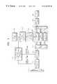
- FIG. 1is a schematic block diagram of a laser video projector according to the present invention
- FIG. 2shows the schematic arrangement of an optical system of the laser video projector of FIG. 1;
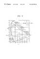
- FIG. 3is a chromatic diagram showing a chrominance realizing performance, considering the change of the spectral luminous sensitivity of eyes according to the wavelengths of light.
- the laser video projectorit is possible to obtain better picture quality not by forming an image by primary video displaying means but by scanning modulated light to a screen, to remarkably improve brightness by using a high-output light source, to project an image without conventional video displaying means such as a cathode ray tube and a liquid crystal display, and to display a color closer to a natural color by using a light source of white light having main wavelengths and a dichroic mirror which can separate the main wavelengths.
- FIG. 1is a schematic block diagram of a laser video projector according to the present invention.
- the laser video projector for projecting an image to a plurality of screens according to the present inventionincludes a light source 100 for emitting white light, an optical system 200 for collecting the white light emitted from the light source 100 in the form of a beam, a light separator 250 for separating the laser beam of white light incident from the optical system 200 into beams of red, green, and blue monochromatic lights, a video signal generator 300 for providing a predetermined video signal, a synchronizing signal separator 350 for separating horizontal and vertical synchronizing signals from the video signal provided from the video signal generator, a chrominance signal separating decoder 400 for separating a chrominance signal from the video signal provided from the video signal generator 300 , a high frequency signal amplifier 500 for amplifying the chrominance signal separated from the chrominance signal separating decoder 400 , a light modulator 600 for modulating the beam incident from the optical system 200 using
- the embodiment of the laser video projector having the above structureis shown in FIG. 2 .
- the light source 100is formed of white light laser for generating white light.
- the main wavelengths of the white light laser beam emitted from the light sourceare respectively 488 nm, 514 nm, and 647 nm.
- the optical system 200comprised of a high reflection mirror 21 for changing the path of the laser beam generated from the light source 100 , a collimating lens 22 for changing the laser beam into parallel light, and telescoping lenses 23 and 24 for reducing the size of the parallel beam is arranged on the light path of the light source 100 .
- the laser beam having a uniform divergence anglebecomes a parallel beam, passing through the collimating lens 22 and comes to have a beam size reduced by the scaling ratios of the two lenses constructing the telescoping lens, passing through the telescoping lenses.
- the size of the beamis reduced so as to most effectively perform light modulation by an acousto-optic modulator (AOM) installed in a limited space.
- AOMacousto-optic modulator
- the light separator 250separates the laser beam of the white light incident from the telescoping lenses 23 and 24 of the optical system 200 into red, green, and blue monochromatic lights.
- the light separator 250includes two dichroic mirrors 67 a and 68 a and a high reflection mirror 69 a.
- the dichroic mirror 67 areflects at least 99% of blue light and transmits at least 95% of lights of other wavelengths.
- the dichroic mirror 68 areflects at least 99% of the green light and transmits at least 95% of the red light.
- the high reflection mirror 69 areflects the transmitted red light and makes the reflected light incident on an acousto-optic modulator 63 .
- a dichroic mirrorwhich remarkably improves a transmission factor and a reflectivity with respect to the main wavelengths of the light source 100 , i.e., 488 nm, 514 nm, and 647 nm is used as the dichroic mirror.
- the thickness of the beam incident on light modulators 61 , 62 , and 63 passing through the light separator 250should be 200 ⁇ m, which is possible by installing focusing lenses 64 a, 65 a, and 66 a at the leading ends of the light modulators 61 , 62 , and 63 by a uniform distance.
- the distance between the focusing lenses 64 a, 65 a, and 66 a and the light modulators 61 , 62 , and 63is determined according to the size of the beam incident on the focusing lenses 64 a, 65 a, and 66 a.
- the distance between the focusing lenses 64 a, 65 a, and 66 a and the light modulators 61 , 62 , and 63 for obtaining a 200 ⁇ m beam waist diameter from the light modulators 61 , 62 , and 63becomes smaller.
- the size of the beamis reduced too much, the lenses or the mirrors are damaged since the light intensity per unit area increases. Therefore, it is necessary to determine the appropriate size of the diameter of the beam.
- the light modulator 600includes three AOMs 61 , 62 , and 63 for modulating the beams of red, green, and blue monochromatic lights obtained by separating the beam of the white light, in the video signal provided by the video signal generator 300 , provided by the light source 100 according to the chrominance signal (amplified by the high frequency amplifier 500 ) separated by a decoder 400 through the optical system 200 and the light separator 250 to the optical signals of the monochromatic lights.
- the light combining unit 650combines the beams of the monochromatic lights modulated to the optical signals by the acousto-optic modulators 61 , 62 , and 63 and forms a video signal in the form of a beam of various colors.
- the light combining unit 650is comprised of dichroic mirrors 67 b and 68 b installed for combining the beams of the monochromatic lights into the video signal in the form of the beam to be projected to the screen 900 and a high reflection mirror 69 b for changing the path of the separated monochromatic light.
- the vertical scanner 700includes a galvanometer.
- the horizontal scanner 800includes a polygonal mirror.
- the laser video projector for projecting an image to a plurality of screens having the above structureoperates as follows.
- the white light emitted from the light source 100is reflected to the high reflection mirror 21 and becomes the laser beam in the form of parallel light in the collimating lens 22 .
- the laser beamis separated into blue, green, and red lights, passing through the telescoping lenses 23 and 24 and the dichroic mirrors 67 a and 68 a.
- the separated lightsare incident on the acousto-optic modulators 61 , 62 , and 63 . Namely, at least 99% of the blue light is reflected from the dichroic mirror 67 a and is incident on the acousto-optic modulator 61 . At least 95% of the light of the remaining wavelengths is transmitted.
- At least 99% of the green lightis reflected from the dichroic mirror 68 a and is incident on the acousto-optic modulator 62 . At least 95% of the red light is transmitted. The transmitted red light is reflected by the high reflection mirror 69 a and is incident on the acousto-optic modulator 63 .
- the dichroic mirroris installed so as to remarkably improve the transmission factor and the reflectivity with respect to the main wavelengths.
- FIG. 3is a chromatic diagram showing a chrominance realizing performance.
- the inside area of a triangledenotes the chrominance realizing performance.
- the triangle marked by a solid linedenotes a chrominance realizing performance in the laser video projector according to the present invention.
- the triangle marked by a dotted linedenotes a chrominance realizing performance of a conventional cathode ray tube television.
- a natural color areais marked with a thick curved line.
- the wavelengths of mainly used colorsare around 470 nm, 540 nm, and 615 nm. It is noted that the chrominance realizing performance of the cathode ray tube television is much poorer than that of the laser video projector according to the present invention. In order to maintain the excellent chrominance realizing performance of the laser video projector 100%, the dichroic mirror should be completely designed. If a color breakup is not completely performed, the apexes of the triangle move inward by a ratio in which the color breakup is not performed. Accordingly, the chrominance realizing performance is reduced.
- the chrominance signals of the blue, green, and red lightsare separated by the chrominance signal separation decoder 400 in the video signal provided by the video signal generator 300 .
- the focal lenses 64 a, 65 a, and 66 a having an appropriate focal distance, arranged at the leading ends of the acousto-optic modulatorsare for maximizing the optical efficiency of the acousto-optic modulators 61 , 62 , and 63 .
- the lenses 64 b, 65 b, and 66 b having the same focal distance as that of the focal lenses 64 a, 65 a and 66 a, placed at the lagging ends of the acousto-optic modulators 61 , 62 , and 63are for restoring the size of the laser beams of the modulated monochromatic lights to the size of the laser beam in the form of the parallel light before being incident on the focal lenses 64 a, 65 a and 66 a.
- the modulated blue, green, and red monochromatic lightsare composed to a beam by the dichroic mirrors 67 b and 68 b and the high reflection mirror 69 b. The green light is reflected from the dichroic mirror 68 b.
- the red lightpasses through the dichroic mirror 68 b.
- the blue lightpasses through the dichroic mirror 67 b.
- the red and green lightsare reflected from the dichroic mirror 67 b.
- the design of the dichroic mirror and the separation order of the blue, green, and red lightscan vary.
- the light composed by the light combining unit 650is vertically scanned by the vertical scanner 700 and horizontally scanned by the horizontal scanner 800 . Accordingly, a picture is focused on a screen 900 .
- Relay lenses 31 and 32are included between the galvanometer of the vertical scanner 700 and the polygonal mirror of the horizontal scanner 800 .
- the galvanometer of the vertical scanner 700moves up and down at a speed synchronized by the vertical synchronizing signal separated from a horizontal or vertical synchronizing signal separator 350 .
- the polygonal mirror of the horizontal scanner 800rotates at a speed synchronized by the horizontal synchronizing signal separated from the horizontal or vertical synchronizing signal separator 350 . Namely, the scanning path of the modulated beam is changed to be vertical by the galvanometer 700 .
- the scanning path of the modulated beamis changed to be horizontal by the polygonal mirror 800 . Accordingly, the beam is scanned to the entire surface of the screen 900 .
- the relay lenses 31 and 32 between the galvanometer 700 and the polygonal mirror 800collects light so that the vertically scanned laser beam is incident within the effective area of the polygonal mirror which is the horizontal scanning surface.
- the relay lenses 31 and 32 having the same focal distanceare separated from each other by the addition of the focal distances.
- a f ⁇ lens 34is installed at the leading end on the side of the screen 900 of the polygonal mirror 800 .
- the f ⁇ lens 34corrects the shape and the size of the beam focused on the screen to be identical in the entire area of the screen.
- the f ⁇ lenscontrols the divergence angle of the beam scanned to the screen, thus controlling the size of the beam required on the screen. Namely, the f ⁇ lens controls the picture of the screen to always be natural even when the screen 900 moves back and forth.
- the laser video projector according to the present inventioncan be used for out door advertisements or a laser television of a large screen since it is possible to realize a large screen having high brightness and high resolution which is difficult to realize by the conventional video projector.
Landscapes
- Physics & Mathematics (AREA)
- Optics & Photonics (AREA)
- Engineering & Computer Science (AREA)
- Multimedia (AREA)
- Signal Processing (AREA)
- Mechanical Optical Scanning Systems (AREA)
- Projection Apparatus (AREA)
- Video Image Reproduction Devices For Color Tv Systems (AREA)
Abstract
Description
Claims (18)
Priority Applications (1)
| Application Number | Priority Date | Filing Date | Title |
|---|---|---|---|
| US09/276,673US6426781B1 (en) | 1999-03-26 | 1999-03-26 | Laser video projector |
Applications Claiming Priority (1)
| Application Number | Priority Date | Filing Date | Title |
|---|---|---|---|
| US09/276,673US6426781B1 (en) | 1999-03-26 | 1999-03-26 | Laser video projector |
Publications (1)
| Publication Number | Publication Date |
|---|---|
| US6426781B1true US6426781B1 (en) | 2002-07-30 |
Family
ID=23057627
Family Applications (1)
| Application Number | Title | Priority Date | Filing Date |
|---|---|---|---|
| US09/276,673Expired - Fee RelatedUS6426781B1 (en) | 1999-03-26 | 1999-03-26 | Laser video projector |
Country Status (1)
| Country | Link |
|---|---|
| US (1) | US6426781B1 (en) |
Cited By (21)
| Publication number | Priority date | Publication date | Assignee | Title |
|---|---|---|---|---|
| US20020060753A1 (en)* | 2000-10-26 | 2002-05-23 | Flint Graham W. | Digital display system using pulsed lasers |
| US20020063854A1 (en)* | 2000-10-26 | 2002-05-30 | Flint Graham W. | Multi-screen laser projection system using a shared laser source |
| US20030011751A1 (en)* | 2001-07-10 | 2003-01-16 | Canon Kabushiki Kaisha | Projection display device |
| US20030091279A1 (en)* | 2001-11-10 | 2003-05-15 | Samsung Electronics Co., Ltd. | Optical coupling device, method of producing the same, and optical apparatus using the same |
| US6665048B2 (en)* | 2002-01-22 | 2003-12-16 | Creo Inc. | Method for imaging a continuously moving object |
| US20040090679A1 (en)* | 2002-11-13 | 2004-05-13 | Eastman Kodak Company | Projection display apparatus having both incoherent and laser light sources |
| US20040160536A1 (en)* | 2002-05-03 | 2004-08-19 | Childers Winthrop D. | Light emitting device projection methods and systems |
| US20040189589A1 (en)* | 2003-01-27 | 2004-09-30 | Lg Electronics Inc. | Laser display system |
| US20040264873A1 (en)* | 2003-06-30 | 2004-12-30 | Smith Trevor D. | Fiber optic connector holder and method |
| US20050041000A1 (en)* | 2003-07-16 | 2005-02-24 | Plut William J. | Projection-type display devices with reduced weight and size |
| WO2005122559A1 (en)* | 2004-06-09 | 2005-12-22 | Ricardo Simoyama Napoli | Constructive device introduced in laser image projector |
| US20060007362A1 (en)* | 2004-06-09 | 2006-01-12 | Samsung Electronics Co., Ltd. | Apparatus for and method of scaling a scanning angle and image projection apparatus incorporating the same |
| EP1706781A1 (en)* | 2004-01-20 | 2006-10-04 | Symbol Technologies, Inc. | Electronic alignment of acousto-optic modulator for modulating a laser |
| US20070195276A1 (en)* | 2003-07-16 | 2007-08-23 | Plut William J | Projection-type display devices with reduced speckle |
| US20070279536A1 (en)* | 2006-06-05 | 2007-12-06 | Chinh Tan | Arrangement for and method of projecting an image to be viewed over extended viewing range |
| US20080112028A1 (en)* | 2006-11-10 | 2008-05-15 | Infocus Corporation | Color laser image generation |
| EP1988419A1 (en) | 2007-04-30 | 2008-11-05 | OSRAM Opto Semiconductors GmbH | Beam combiner for a multi-colour laser display |
| US20080273568A1 (en)* | 2007-04-30 | 2008-11-06 | Osram Opto Semiconductors Gmbh | Beam combiner for a multicolor laser display |
| US20090316243A1 (en)* | 2006-09-15 | 2009-12-24 | Nec Corporation | Laser Projector |
| US20100231868A1 (en)* | 2009-03-13 | 2010-09-16 | Alvis Technologies Inc. | Display device |
| US20110075055A1 (en)* | 2009-09-30 | 2011-03-31 | Apple Inc. | Display system having coherent and incoherent light sources |
Citations (10)
| Publication number | Priority date | Publication date | Assignee | Title |
|---|---|---|---|---|
| US4720747A (en)* | 1984-04-26 | 1988-01-19 | Corporation For Laser Optics Research | Sequential plane projection by laser video projector |
| US4851918A (en)* | 1984-04-26 | 1989-07-25 | Corporation For Laser Optic Research | Sequential plane projection by laser video projector |
| US5253073A (en)* | 1992-04-01 | 1993-10-12 | Corporation For Laser Optics Research | Electronic data multiplexing in a full color pulsed laser projector and method |
| US5255082A (en)* | 1990-11-30 | 1993-10-19 | Sony Corporation | Laser beam color image display apparatus |
| US5317348A (en)* | 1992-12-01 | 1994-05-31 | Knize Randall J | Full color solid state laser projector system |
| US5715021A (en)* | 1993-02-03 | 1998-02-03 | Nitor | Methods and apparatus for image projection |
| US5774174A (en)* | 1996-02-07 | 1998-06-30 | Hardie; Robert Joseph | Laser projector |
| US6018408A (en)* | 1999-03-26 | 2000-01-25 | Samsung Electronics Co., Ltd. | Laser projection display apparatus |
| US6020937A (en)* | 1997-05-12 | 2000-02-01 | Sony Corporation | High resolution digital projection TV with dynamically adjustable resolution utilizing a system of rotating mirrors |
| US6170953B1 (en)* | 1999-03-22 | 2001-01-09 | Samsung Electronics Co., Ltd. | Laser video projector for projecting image to a plurality of screens |
- 1999
- 1999-03-26USUS09/276,673patent/US6426781B1/ennot_activeExpired - Fee Related
Patent Citations (11)
| Publication number | Priority date | Publication date | Assignee | Title |
|---|---|---|---|---|
| US4720747A (en)* | 1984-04-26 | 1988-01-19 | Corporation For Laser Optics Research | Sequential plane projection by laser video projector |
| US4851918A (en)* | 1984-04-26 | 1989-07-25 | Corporation For Laser Optic Research | Sequential plane projection by laser video projector |
| US5255082A (en)* | 1990-11-30 | 1993-10-19 | Sony Corporation | Laser beam color image display apparatus |
| US5253073A (en)* | 1992-04-01 | 1993-10-12 | Corporation For Laser Optics Research | Electronic data multiplexing in a full color pulsed laser projector and method |
| US5317348A (en)* | 1992-12-01 | 1994-05-31 | Knize Randall J | Full color solid state laser projector system |
| US5715021A (en)* | 1993-02-03 | 1998-02-03 | Nitor | Methods and apparatus for image projection |
| US5920361A (en)* | 1993-02-03 | 1999-07-06 | Nitor | Methods and apparatus for image projection |
| US5774174A (en)* | 1996-02-07 | 1998-06-30 | Hardie; Robert Joseph | Laser projector |
| US6020937A (en)* | 1997-05-12 | 2000-02-01 | Sony Corporation | High resolution digital projection TV with dynamically adjustable resolution utilizing a system of rotating mirrors |
| US6170953B1 (en)* | 1999-03-22 | 2001-01-09 | Samsung Electronics Co., Ltd. | Laser video projector for projecting image to a plurality of screens |
| US6018408A (en)* | 1999-03-26 | 2000-01-25 | Samsung Electronics Co., Ltd. | Laser projection display apparatus |
Cited By (45)
| Publication number | Priority date | Publication date | Assignee | Title |
|---|---|---|---|---|
| US20020060753A1 (en)* | 2000-10-26 | 2002-05-23 | Flint Graham W. | Digital display system using pulsed lasers |
| US20020063854A1 (en)* | 2000-10-26 | 2002-05-30 | Flint Graham W. | Multi-screen laser projection system using a shared laser source |
| US6975366B2 (en)* | 2000-10-26 | 2005-12-13 | General Atomics | Digital display system using pulsed lasers |
| US6771326B2 (en)* | 2000-10-26 | 2004-08-03 | General Atomics, Inc. | Multi-screen laser projection system using a shared laser source |
| US20030011751A1 (en)* | 2001-07-10 | 2003-01-16 | Canon Kabushiki Kaisha | Projection display device |
| US6945652B2 (en)* | 2001-07-10 | 2005-09-20 | Canon Kabushiki Kaisha | Projection display device |
| US20030091279A1 (en)* | 2001-11-10 | 2003-05-15 | Samsung Electronics Co., Ltd. | Optical coupling device, method of producing the same, and optical apparatus using the same |
| US20050123239A1 (en)* | 2001-11-10 | 2005-06-09 | Samsung Electronics Co., Ltd. | Optical coupling device, method of producing the same, and optical apparatus using the same |
| US6865309B2 (en)* | 2001-11-10 | 2005-03-08 | Samsung Electronics Co., Ltd. | Optical coupling device, method of producing the same, and optical apparatus using the same |
| US6665048B2 (en)* | 2002-01-22 | 2003-12-16 | Creo Inc. | Method for imaging a continuously moving object |
| US20040160536A1 (en)* | 2002-05-03 | 2004-08-19 | Childers Winthrop D. | Light emitting device projection methods and systems |
| US7230657B2 (en) | 2002-05-03 | 2007-06-12 | Hewlett-Packard Development Company, L.P. | Light emitting device projection methods and systems |
| US6807010B2 (en) | 2002-11-13 | 2004-10-19 | Eastman Kodak Company | Projection display apparatus having both incoherent and laser light sources |
| US20040090679A1 (en)* | 2002-11-13 | 2004-05-13 | Eastman Kodak Company | Projection display apparatus having both incoherent and laser light sources |
| US20040189589A1 (en)* | 2003-01-27 | 2004-09-30 | Lg Electronics Inc. | Laser display system |
| US7245280B2 (en)* | 2003-01-27 | 2007-07-17 | Lg Electronics Inc. | Laser display system |
| US20040264873A1 (en)* | 2003-06-30 | 2004-12-30 | Smith Trevor D. | Fiber optic connector holder and method |
| US20070195276A1 (en)* | 2003-07-16 | 2007-08-23 | Plut William J | Projection-type display devices with reduced speckle |
| US7510284B2 (en) | 2003-07-16 | 2009-03-31 | Plut William J | Projection-type display devices including redundant laser sets |
| US7156522B2 (en) | 2003-07-16 | 2007-01-02 | Plut William J | Projection-type display devices with reduced weight and size |
| US8641209B2 (en) | 2003-07-16 | 2014-02-04 | Transpacific Image, Llc | Positioning interfaces for projection display devices |
| US8366282B2 (en) | 2003-07-16 | 2013-02-05 | Transpacific Image, Llc | Positioning interfaces for projection display devices |
| US20050041000A1 (en)* | 2003-07-16 | 2005-02-24 | Plut William J. | Projection-type display devices with reduced weight and size |
| US20070205300A1 (en)* | 2003-07-16 | 2007-09-06 | Plut William J | Positioning interfaces for projection display devices |
| US7281807B2 (en) | 2003-07-16 | 2007-10-16 | Honeywood Technologies, Llc | Positionable projection display devices |
| US8147074B2 (en) | 2003-07-16 | 2012-04-03 | Transpacific Image, Llc | Positioning interfaces for projection display devices |
| USRE42251E1 (en)* | 2003-07-16 | 2011-03-29 | Transpacific Image, Llc | Projection-type display devices with reduced weight and size |
| US7806535B2 (en) | 2003-07-16 | 2010-10-05 | Plut William J | Low power projection display devices |
| US20100171936A1 (en)* | 2003-07-16 | 2010-07-08 | Plut William J | Positioning interfaces for projection display devices |
| US7703930B2 (en) | 2003-07-16 | 2010-04-27 | Plut William J | Positioning interfaces for projection display devices |
| EP1706781A1 (en)* | 2004-01-20 | 2006-10-04 | Symbol Technologies, Inc. | Electronic alignment of acousto-optic modulator for modulating a laser |
| US7701412B2 (en) | 2004-06-09 | 2010-04-20 | Samsung Electronics Co., Ltd | Apparatus for and method of scaling a scanning angle and image projection apparatus incorporating the same |
| US20060007362A1 (en)* | 2004-06-09 | 2006-01-12 | Samsung Electronics Co., Ltd. | Apparatus for and method of scaling a scanning angle and image projection apparatus incorporating the same |
| WO2005122559A1 (en)* | 2004-06-09 | 2005-12-22 | Ricardo Simoyama Napoli | Constructive device introduced in laser image projector |
| US20070279536A1 (en)* | 2006-06-05 | 2007-12-06 | Chinh Tan | Arrangement for and method of projecting an image to be viewed over extended viewing range |
| US20090316243A1 (en)* | 2006-09-15 | 2009-12-24 | Nec Corporation | Laser Projector |
| US8519324B2 (en)* | 2006-09-15 | 2013-08-27 | Nec Corporation | Laser projector for projecting and displaying an image based on the raster scanning of a laser beam |
| US7993005B2 (en)* | 2006-11-10 | 2011-08-09 | Seiko Epson Corporation | Color laser image generation |
| US20080112028A1 (en)* | 2006-11-10 | 2008-05-15 | Infocus Corporation | Color laser image generation |
| DE102007034958A1 (en) | 2007-04-30 | 2008-11-06 | Osram Opto Semiconductors Gmbh | Beam combiner for a multicolored laser display |
| EP1988419A1 (en) | 2007-04-30 | 2008-11-05 | OSRAM Opto Semiconductors GmbH | Beam combiner for a multi-colour laser display |
| US20080273568A1 (en)* | 2007-04-30 | 2008-11-06 | Osram Opto Semiconductors Gmbh | Beam combiner for a multicolor laser display |
| US20100231868A1 (en)* | 2009-03-13 | 2010-09-16 | Alvis Technologies Inc. | Display device |
| US20110075055A1 (en)* | 2009-09-30 | 2011-03-31 | Apple Inc. | Display system having coherent and incoherent light sources |
| US8502926B2 (en)* | 2009-09-30 | 2013-08-06 | Apple Inc. | Display system having coherent and incoherent light sources |
Similar Documents
| Publication | Publication Date | Title |
|---|---|---|
| US6170953B1 (en) | Laser video projector for projecting image to a plurality of screens | |
| US6426781B1 (en) | Laser video projector | |
| US7131730B2 (en) | Illumination optical system and projection display optical system | |
| JP4182374B2 (en) | Projection display | |
| JPH07151995A (en) | Image projection device | |
| JP3264916B2 (en) | Color projector | |
| JP2003066369A (en) | Image display device, control method of image display device, image processing system | |
| KR100381050B1 (en) | Optical System Of Liquid Crystal Projector | |
| KR100215298B1 (en) | A compacted beam pass expander and the method for expanding beam pass | |
| KR100252157B1 (en) | Projection television set | |
| KR100408504B1 (en) | Laser image projection system and the method thereof | |
| KR100425336B1 (en) | Laser image projector for projecting to multi-screen | |
| KR19980020617A (en) | Laser image projection device | |
| KR100300951B1 (en) | Image projection method and device | |
| KR100408505B1 (en) | Laser image projector | |
| JP2768345B2 (en) | LCD projector | |
| JP4928909B2 (en) | Projection display | |
| KR100695130B1 (en) | Laser Image Projection System Using Hybrid Optical Integration / Separation Device | |
| EP0961501A2 (en) | Color image projecting device | |
| JP2532375B2 (en) | Color LCD projector | |
| JPH0949997A (en) | Liquid crystal display device | |
| JPH0949995A (en) | Liquid crystal display device | |
| JP3550261B2 (en) | LCD projector | |
| KR100645429B1 (en) | Image Projection Device Using Optical Coupling Element | |
| JPWO2020144983A1 (en) | Light source device and image display device |
Legal Events
| Date | Code | Title | Description |
|---|---|---|---|
| AS | Assignment | Owner name:SAMSUNG ELECTRONICS CO., LTD., KOREA, REPUBLIC OF Free format text:ASSIGNMENT OF ASSIGNORS INTEREST;ASSIGNOR:LEE, JIN-HO;REEL/FRAME:009858/0059 Effective date:19990211 | |
| FEPP | Fee payment procedure | Free format text:PAYOR NUMBER ASSIGNED (ORIGINAL EVENT CODE: ASPN); ENTITY STATUS OF PATENT OWNER: LARGE ENTITY | |
| FPAY | Fee payment | Year of fee payment:4 | |
| FEPP | Fee payment procedure | Free format text:PAYER NUMBER DE-ASSIGNED (ORIGINAL EVENT CODE: RMPN); ENTITY STATUS OF PATENT OWNER: LARGE ENTITY Free format text:PAYOR NUMBER ASSIGNED (ORIGINAL EVENT CODE: ASPN); ENTITY STATUS OF PATENT OWNER: LARGE ENTITY | |
| REMI | Maintenance fee reminder mailed | ||
| AS | Assignment | Owner name:SAMSUNG LED CO., LTD.,KOREA, DEMOCRATIC PEOPLE'S R Free format text:ASSIGNMENT OF ASSIGNORS INTEREST;ASSIGNOR:SAMSUNG ELECTRONICS CO., LTD.;REEL/FRAME:024185/0841 Effective date:20100126 | |
| FPAY | Fee payment | Year of fee payment:8 | |
| SULP | Surcharge for late payment | Year of fee payment:7 | |
| AS | Assignment | Owner name:SAMSUNG ELECTRONICS CO., LTD., KOREA, REPUBLIC OF Free format text:MERGER;ASSIGNOR:SAMSUNG LED CO., LTD.;REEL/FRAME:028744/0272 Effective date:20120403 | |
| REMI | Maintenance fee reminder mailed | ||
| LAPS | Lapse for failure to pay maintenance fees | ||
| STCH | Information on status: patent discontinuation | Free format text:PATENT EXPIRED DUE TO NONPAYMENT OF MAINTENANCE FEES UNDER 37 CFR 1.362 | |
| FP | Lapsed due to failure to pay maintenance fee | Effective date:20140730 |