US6426289B1 - Method of fabricating a barrier layer associated with a conductor layer in damascene structures - Google Patents
Method of fabricating a barrier layer associated with a conductor layer in damascene structuresDownload PDFInfo
- Publication number
- US6426289B1 US6426289B1US09/534,224US53422400AUS6426289B1US 6426289 B1US6426289 B1US 6426289B1US 53422400 AUS53422400 AUS 53422400AUS 6426289 B1US6426289 B1US 6426289B1
- Authority
- US
- United States
- Prior art keywords
- layer
- kev
- conductor
- ions
- bottommost
- Prior art date
- Legal status (The legal status is an assumption and is not a legal conclusion. Google has not performed a legal analysis and makes no representation as to the accuracy of the status listed.)
- Expired - Lifetime
Links
- 230000004888barrier functionEffects0.000titleclaimsabstractdescription54
- 239000004020conductorSubstances0.000titleclaimsdescription28
- 238000004519manufacturing processMethods0.000titleclaimsdescription12
- 238000000034methodMethods0.000claimsabstractdescription59
- 229910052751metalInorganic materials0.000claimsabstractdescription36
- 239000002184metalSubstances0.000claimsabstractdescription36
- 238000007747platingMethods0.000claimsabstractdescription29
- 239000010949copperSubstances0.000claimsdescription27
- 150000002500ionsChemical class0.000claimsdescription27
- VYPSYNLAJGMNEJ-UHFFFAOYSA-NSilicium dioxideChemical compoundO=[Si]=OVYPSYNLAJGMNEJ-UHFFFAOYSA-N0.000claimsdescription20
- 239000002019doping agentSubstances0.000claimsdescription20
- 229910052726zirconiumInorganic materials0.000claimsdescription19
- QCWXUUIWCKQGHC-UHFFFAOYSA-NZirconiumChemical compound[Zr]QCWXUUIWCKQGHC-UHFFFAOYSA-N0.000claimsdescription18
- RYGMFSIKBFXOCR-UHFFFAOYSA-NCopperChemical compound[Cu]RYGMFSIKBFXOCR-UHFFFAOYSA-N0.000claimsdescription12
- 229910052802copperInorganic materials0.000claimsdescription12
- 238000000151depositionMethods0.000claimsdescription10
- 235000012239silicon dioxideNutrition0.000claimsdescription10
- 239000000377silicon dioxideSubstances0.000claimsdescription10
- 229910052715tantalumInorganic materials0.000claimsdescription10
- 229910052721tungstenInorganic materials0.000claimsdescription10
- 229910052782aluminiumInorganic materials0.000claimsdescription9
- XAGFODPZIPBFFR-UHFFFAOYSA-NaluminiumChemical compound[Al]XAGFODPZIPBFFR-UHFFFAOYSA-N0.000claimsdescription9
- ZOKXTWBITQBERF-UHFFFAOYSA-NMolybdenumChemical compound[Mo]ZOKXTWBITQBERF-UHFFFAOYSA-N0.000claimsdescription8
- 229910052581Si3N4Inorganic materials0.000claimsdescription8
- 229910052735hafniumInorganic materials0.000claimsdescription8
- 229910052750molybdenumInorganic materials0.000claimsdescription8
- 239000011733molybdenumSubstances0.000claimsdescription8
- HQVNEWCFYHHQES-UHFFFAOYSA-Nsilicon nitrideChemical compoundN12[Si]34N5[Si]62N3[Si]51N64HQVNEWCFYHHQES-UHFFFAOYSA-N0.000claimsdescription8
- WFKWXMTUELFFGS-UHFFFAOYSA-NtungstenChemical compound[W]WFKWXMTUELFFGS-UHFFFAOYSA-N0.000claimsdescription8
- 239000010937tungstenSubstances0.000claimsdescription8
- VYZAMTAEIAYCRO-UHFFFAOYSA-NChromiumChemical compound[Cr]VYZAMTAEIAYCRO-UHFFFAOYSA-N0.000claimsdescription7
- RTAQQCXQSZGOHL-UHFFFAOYSA-NTitaniumChemical compound[Ti]RTAQQCXQSZGOHL-UHFFFAOYSA-N0.000claimsdescription7
- 229910052804chromiumInorganic materials0.000claimsdescription7
- 239000011651chromiumSubstances0.000claimsdescription7
- VBJZVLUMGGDVMO-UHFFFAOYSA-Nhafnium atomChemical compound[Hf]VBJZVLUMGGDVMO-UHFFFAOYSA-N0.000claimsdescription7
- 239000010955niobiumSubstances0.000claimsdescription7
- GUCVJGMIXFAOAE-UHFFFAOYSA-Nniobium atomChemical compound[Nb]GUCVJGMIXFAOAE-UHFFFAOYSA-N0.000claimsdescription7
- GUVRBAGPIYLISA-UHFFFAOYSA-Ntantalum atomChemical compound[Ta]GUVRBAGPIYLISA-UHFFFAOYSA-N0.000claimsdescription7
- 229910052719titaniumInorganic materials0.000claimsdescription7
- 239000010936titaniumSubstances0.000claimsdescription7
- 229910052720vanadiumInorganic materials0.000claimsdescription7
- 239000004642PolyimideSubstances0.000claimsdescription6
- 239000003989dielectric materialSubstances0.000claimsdescription6
- 238000005468ion implantationMethods0.000claimsdescription6
- 229920001721polyimidePolymers0.000claimsdescription6
- 238000007772electroless platingMethods0.000claimsdescription5
- 239000007943implantSubstances0.000claimsdescription5
- 229920000642polymerPolymers0.000claimsdescription4
- ZOXJGFHDIHLPTG-UHFFFAOYSA-NBoronChemical compound[B]ZOXJGFHDIHLPTG-UHFFFAOYSA-N0.000claimsdescription3
- FYYHWMGAXLPEAU-UHFFFAOYSA-NMagnesiumChemical compound[Mg]FYYHWMGAXLPEAU-UHFFFAOYSA-N0.000claimsdescription3
- 229910052796boronInorganic materials0.000claimsdescription3
- 229910052749magnesiumInorganic materials0.000claimsdescription3
- 239000011777magnesiumSubstances0.000claimsdescription3
- 150000004767nitridesChemical class0.000claimsdescription3
- LEONUFNNVUYDNQ-UHFFFAOYSA-Nvanadium atomChemical compound[V]LEONUFNNVUYDNQ-UHFFFAOYSA-N0.000claims1
- 239000000463materialSubstances0.000abstractdescription12
- 238000005530etchingMethods0.000abstractdescription4
- 238000011109contaminationMethods0.000abstractdescription3
- 239000004065semiconductorSubstances0.000description10
- 239000000758substrateSubstances0.000description9
- NBIIXXVUZAFLBC-UHFFFAOYSA-NPhosphoric acidChemical compoundOP(O)(O)=ONBIIXXVUZAFLBC-UHFFFAOYSA-N0.000description6
- 150000002739metalsChemical class0.000description6
- 230000008569processEffects0.000description6
- GPPXJZIENCGNKB-UHFFFAOYSA-NvanadiumChemical compound[V]#[V]GPPXJZIENCGNKB-UHFFFAOYSA-N0.000description6
- XUIMIQQOPSSXEZ-UHFFFAOYSA-NSiliconChemical compound[Si]XUIMIQQOPSSXEZ-UHFFFAOYSA-N0.000description5
- 238000012545processingMethods0.000description5
- 229910052710siliconInorganic materials0.000description5
- 239000010703siliconSubstances0.000description5
- PWHULOQIROXLJO-UHFFFAOYSA-NManganeseChemical compound[Mn]PWHULOQIROXLJO-UHFFFAOYSA-N0.000description4
- KJTLSVCANCCWHF-UHFFFAOYSA-NRutheniumChemical compound[Ru]KJTLSVCANCCWHF-UHFFFAOYSA-N0.000description4
- 229910045601alloyInorganic materials0.000description4
- 239000000956alloySubstances0.000description4
- 238000009792diffusion processMethods0.000description4
- 229910052748manganeseInorganic materials0.000description4
- 239000011572manganeseSubstances0.000description4
- 229910052758niobiumInorganic materials0.000description4
- 229910052762osmiumInorganic materials0.000description4
- SYQBFIAQOQZEGI-UHFFFAOYSA-Nosmium atomChemical compound[Os]SYQBFIAQOQZEGI-UHFFFAOYSA-N0.000description4
- 239000003870refractory metalSubstances0.000description4
- 229910052702rheniumInorganic materials0.000description4
- WUAPFZMCVAUBPE-UHFFFAOYSA-Nrhenium atomChemical compound[Re]WUAPFZMCVAUBPE-UHFFFAOYSA-N0.000description4
- 229910052707rutheniumInorganic materials0.000description4
- 230000008021depositionEffects0.000description3
- DDFHBQSCUXNBSA-UHFFFAOYSA-N5-(5-carboxythiophen-2-yl)thiophene-2-carboxylic acidChemical compoundS1C(C(=O)O)=CC=C1C1=CC=C(C(O)=O)S1DDFHBQSCUXNBSA-UHFFFAOYSA-N0.000description2
- 239000002253acidSubstances0.000description2
- 229910000147aluminium phosphateInorganic materials0.000description2
- LDDQLRUQCUTJBB-UHFFFAOYSA-Nammonium fluorideChemical compound[NH4+].[F-]LDDQLRUQCUTJBB-UHFFFAOYSA-N0.000description2
- 239000010953base metalSubstances0.000description2
- 230000015572biosynthetic processEffects0.000description2
- 239000003990capacitorSubstances0.000description2
- 239000003054catalystSubstances0.000description2
- 230000008878couplingEffects0.000description2
- 238000010168coupling processMethods0.000description2
- 238000005859coupling reactionMethods0.000description2
- 230000032798delaminationEffects0.000description2
- 238000000454electroless metal depositionMethods0.000description2
- 238000009713electroplatingMethods0.000description2
- 238000005516engineering processMethods0.000description2
- 239000012535impuritySubstances0.000description2
- 239000012212insulatorSubstances0.000description2
- 230000010354integrationEffects0.000description2
- 239000000203mixtureSubstances0.000description2
- 238000006467substitution reactionMethods0.000description2
- 229910000838Al alloyInorganic materials0.000description1
- JBRZTFJDHDCESZ-UHFFFAOYSA-NAsGaChemical compound[As]#[Ga]JBRZTFJDHDCESZ-UHFFFAOYSA-N0.000description1
- 229910001218Gallium arsenideInorganic materials0.000description1
- 229910000577Silicon-germaniumInorganic materials0.000description1
- BQCADISMDOOEFD-UHFFFAOYSA-NSilverChemical compound[Ag]BQCADISMDOOEFD-UHFFFAOYSA-N0.000description1
- NRTOMJZYCJJWKI-UHFFFAOYSA-NTitanium nitrideChemical compound[Ti]#NNRTOMJZYCJJWKI-UHFFFAOYSA-N0.000description1
- LEVVHYCKPQWKOP-UHFFFAOYSA-N[Si].[Ge]Chemical compound[Si].[Ge]LEVVHYCKPQWKOP-UHFFFAOYSA-N0.000description1
- 150000001875compoundsChemical class0.000description1
- 230000003247decreasing effectEffects0.000description1
- 230000007812deficiencyEffects0.000description1
- 238000005137deposition processMethods0.000description1
- 238000013461designMethods0.000description1
- 150000002148estersChemical class0.000description1
- 229910052732germaniumInorganic materials0.000description1
- GNPVGFCGXDBREM-UHFFFAOYSA-Ngermanium atomChemical compound[Ge]GNPVGFCGXDBREM-UHFFFAOYSA-N0.000description1
- PCHJSUWPFVWCPO-UHFFFAOYSA-NgoldChemical compound[Au]PCHJSUWPFVWCPO-UHFFFAOYSA-N0.000description1
- 229910052737goldInorganic materials0.000description1
- 239000010931goldSubstances0.000description1
- 238000011835investigationMethods0.000description1
- 239000003446ligandSubstances0.000description1
- 238000001465metallisationMethods0.000description1
- 238000004377microelectronicMethods0.000description1
- 238000012986modificationMethods0.000description1
- 230000004048modificationEffects0.000description1
- 150000002894organic compoundsChemical class0.000description1
- 238000012856packingMethods0.000description1
- 231100000572poisoningToxicity0.000description1
- 230000000607poisoning effectEffects0.000description1
- 229910052594sapphireInorganic materials0.000description1
- 239000010980sapphireSubstances0.000description1
- 229910052709silverInorganic materials0.000description1
- 239000004332silverSubstances0.000description1
- 238000004544sputter depositionMethods0.000description1
- 230000001629suppressionEffects0.000description1
- 239000011800void materialSubstances0.000description1
- 235000012431wafersNutrition0.000description1
Images


Classifications
- H—ELECTRICITY
- H01—ELECTRIC ELEMENTS
- H01L—SEMICONDUCTOR DEVICES NOT COVERED BY CLASS H10
- H01L21/00—Processes or apparatus adapted for the manufacture or treatment of semiconductor or solid state devices or of parts thereof
- H01L21/70—Manufacture or treatment of devices consisting of a plurality of solid state components formed in or on a common substrate or of parts thereof; Manufacture of integrated circuit devices or of parts thereof
- H01L21/71—Manufacture of specific parts of devices defined in group H01L21/70
- H01L21/768—Applying interconnections to be used for carrying current between separate components within a device comprising conductors and dielectrics
- H01L21/76838—Applying interconnections to be used for carrying current between separate components within a device comprising conductors and dielectrics characterised by the formation and the after-treatment of the conductors
- H01L21/76841—Barrier, adhesion or liner layers
- H01L21/76843—Barrier, adhesion or liner layers formed in openings in a dielectric
- H01L21/76849—Barrier, adhesion or liner layers formed in openings in a dielectric the layer being positioned on top of the main fill metal
- H—ELECTRICITY
- H01—ELECTRIC ELEMENTS
- H01L—SEMICONDUCTOR DEVICES NOT COVERED BY CLASS H10
- H01L21/00—Processes or apparatus adapted for the manufacture or treatment of semiconductor or solid state devices or of parts thereof
- H01L21/70—Manufacture or treatment of devices consisting of a plurality of solid state components formed in or on a common substrate or of parts thereof; Manufacture of integrated circuit devices or of parts thereof
- H01L21/71—Manufacture of specific parts of devices defined in group H01L21/70
- H01L21/768—Applying interconnections to be used for carrying current between separate components within a device comprising conductors and dielectrics
- H01L21/76838—Applying interconnections to be used for carrying current between separate components within a device comprising conductors and dielectrics characterised by the formation and the after-treatment of the conductors
- H01L21/76841—Barrier, adhesion or liner layers
- H01L21/76843—Barrier, adhesion or liner layers formed in openings in a dielectric
- H—ELECTRICITY
- H01—ELECTRIC ELEMENTS
- H01L—SEMICONDUCTOR DEVICES NOT COVERED BY CLASS H10
- H01L21/00—Processes or apparatus adapted for the manufacture or treatment of semiconductor or solid state devices or of parts thereof
- H01L21/70—Manufacture or treatment of devices consisting of a plurality of solid state components formed in or on a common substrate or of parts thereof; Manufacture of integrated circuit devices or of parts thereof
- H01L21/71—Manufacture of specific parts of devices defined in group H01L21/70
- H01L21/768—Applying interconnections to be used for carrying current between separate components within a device comprising conductors and dielectrics
- H01L21/76838—Applying interconnections to be used for carrying current between separate components within a device comprising conductors and dielectrics characterised by the formation and the after-treatment of the conductors
- H01L21/76841—Barrier, adhesion or liner layers
- H01L21/76867—Barrier, adhesion or liner layers characterized by methods of formation other than PVD, CVD or deposition from a liquids
- H—ELECTRICITY
- H01—ELECTRIC ELEMENTS
- H01L—SEMICONDUCTOR DEVICES NOT COVERED BY CLASS H10
- H01L21/00—Processes or apparatus adapted for the manufacture or treatment of semiconductor or solid state devices or of parts thereof
- H01L21/70—Manufacture or treatment of devices consisting of a plurality of solid state components formed in or on a common substrate or of parts thereof; Manufacture of integrated circuit devices or of parts thereof
- H01L21/71—Manufacture of specific parts of devices defined in group H01L21/70
- H01L21/768—Applying interconnections to be used for carrying current between separate components within a device comprising conductors and dielectrics
- H01L21/76838—Applying interconnections to be used for carrying current between separate components within a device comprising conductors and dielectrics characterised by the formation and the after-treatment of the conductors
- H01L21/76841—Barrier, adhesion or liner layers
- H01L21/76871—Layers specifically deposited to enhance or enable the nucleation of further layers, i.e. seed layers
- H01L21/76873—Layers specifically deposited to enhance or enable the nucleation of further layers, i.e. seed layers for electroplating
- H—ELECTRICITY
- H01—ELECTRIC ELEMENTS
- H01L—SEMICONDUCTOR DEVICES NOT COVERED BY CLASS H10
- H01L21/00—Processes or apparatus adapted for the manufacture or treatment of semiconductor or solid state devices or of parts thereof
- H01L21/70—Manufacture or treatment of devices consisting of a plurality of solid state components formed in or on a common substrate or of parts thereof; Manufacture of integrated circuit devices or of parts thereof
- H01L21/71—Manufacture of specific parts of devices defined in group H01L21/70
- H01L21/768—Applying interconnections to be used for carrying current between separate components within a device comprising conductors and dielectrics
- H01L21/76838—Applying interconnections to be used for carrying current between separate components within a device comprising conductors and dielectrics characterised by the formation and the after-treatment of the conductors
- H01L21/76841—Barrier, adhesion or liner layers
- H01L21/76871—Layers specifically deposited to enhance or enable the nucleation of further layers, i.e. seed layers
- H01L21/76874—Layers specifically deposited to enhance or enable the nucleation of further layers, i.e. seed layers for electroless plating
- H—ELECTRICITY
- H01—ELECTRIC ELEMENTS
- H01L—SEMICONDUCTOR DEVICES NOT COVERED BY CLASS H10
- H01L21/00—Processes or apparatus adapted for the manufacture or treatment of semiconductor or solid state devices or of parts thereof
- H01L21/70—Manufacture or treatment of devices consisting of a plurality of solid state components formed in or on a common substrate or of parts thereof; Manufacture of integrated circuit devices or of parts thereof
- H01L21/71—Manufacture of specific parts of devices defined in group H01L21/70
- H01L21/768—Applying interconnections to be used for carrying current between separate components within a device comprising conductors and dielectrics
- H01L21/76838—Applying interconnections to be used for carrying current between separate components within a device comprising conductors and dielectrics characterised by the formation and the after-treatment of the conductors
- H01L21/76877—Filling of holes, grooves or trenches, e.g. vias, with conductive material
- H01L21/76879—Filling of holes, grooves or trenches, e.g. vias, with conductive material by selective deposition of conductive material in the vias, e.g. selective C.V.D. on semiconductor material, plating
- H—ELECTRICITY
- H01—ELECTRIC ELEMENTS
- H01L—SEMICONDUCTOR DEVICES NOT COVERED BY CLASS H10
- H01L21/00—Processes or apparatus adapted for the manufacture or treatment of semiconductor or solid state devices or of parts thereof
- H01L21/70—Manufacture or treatment of devices consisting of a plurality of solid state components formed in or on a common substrate or of parts thereof; Manufacture of integrated circuit devices or of parts thereof
- H01L21/71—Manufacture of specific parts of devices defined in group H01L21/70
- H01L21/768—Applying interconnections to be used for carrying current between separate components within a device comprising conductors and dielectrics
- H01L21/76838—Applying interconnections to be used for carrying current between separate components within a device comprising conductors and dielectrics characterised by the formation and the after-treatment of the conductors
- H01L21/76877—Filling of holes, grooves or trenches, e.g. vias, with conductive material
- H01L21/7688—Filling of holes, grooves or trenches, e.g. vias, with conductive material by deposition over sacrificial masking layer, e.g. lift-off
- H—ELECTRICITY
- H01—ELECTRIC ELEMENTS
- H01L—SEMICONDUCTOR DEVICES NOT COVERED BY CLASS H10
- H01L21/00—Processes or apparatus adapted for the manufacture or treatment of semiconductor or solid state devices or of parts thereof
- H01L21/70—Manufacture or treatment of devices consisting of a plurality of solid state components formed in or on a common substrate or of parts thereof; Manufacture of integrated circuit devices or of parts thereof
- H01L21/71—Manufacture of specific parts of devices defined in group H01L21/70
- H01L21/768—Applying interconnections to be used for carrying current between separate components within a device comprising conductors and dielectrics
- H01L21/76838—Applying interconnections to be used for carrying current between separate components within a device comprising conductors and dielectrics characterised by the formation and the after-treatment of the conductors
- H01L21/76886—Modifying permanently or temporarily the pattern or the conductivity of conductive members, e.g. formation of alloys, reduction of contact resistances
Definitions
- the present inventionrelates to a method of fabricating a barrier layer and more particularly to a method of fabricating a barrier layer on top surfaces of metals in damascene structures utilizing ion implantation.
- VLSIVery large scale integration
- metalssuch as copper, aluminum, gold and silver, as well as others, are used as conductive materials for electrical interconnections in a VLSI integrated circuit.
- aluminum alloysare most commonly used and its alloys have been fully explored and characterized for use as an electrical interconnection in an integrated circuit, and much technology has been developed to aid in the formation of aluminum interconnections.
- Aluminumhas very attractive features for use as an integrated circuit electrical interconnection, such as low electrical resistivity and strong adhesion to silicon dioxide.
- ULSIUltra Large Scale Integration
- barrier layersare necessary due to decreasing dimensions and design rules become increasingly restricted by aluminum interconnection reliability concerns such as electromigration, stress-induced void formation, hillock suppression, and current density limitations.
- CuCopper
- Cuis approximately 40% lower in resistivity than Al and is much more resistant to reliability problems such as electromigration.
- Cuhas been known to cause other reliability problems associated with the high rate of Cu diffusion through silicon substrates and dielectric films.
- One such problemis electrical shorting, wherein the Cu from one Cu interconnect line diffuses into an adjacent dielectric region, forming a conductive path to another Cu interconnect line.
- Another problemis transistor poisoning, wherein Cu diffuses into the underlying silicon substrate and causes junction leakage along with reduced channel mobility in the transistor, thereby destroying the device.
- barrier materialis combined with a ligand, or organic compound, to make the barrier material volatile. That is, the barrier material is vaporized into a gas and the metal is exposed to the barrier material gas in an elevated temperature environment. When the barrier material gas compound decomposes, the barrier is left behind on the metal surface.
- CVDinvolves considerable process complexity, particularly in the fabrication process for the provision of a barrier layer on top surfaces of metals in damascene structures.
- a method of fabricating a barrier layerwhich does not employ CVD and which is cost effective and involves less complexity.
- the present inventionis directed to a simplified, CVD-less method of forming a barrier layer for a metal layer which prevents metal contamination in an integrated circuit.
- the inventionutilizes a sacrificial multilayer dielectric structure and selective etching to form the barrier layer.
- An openingis etched in the structure and a plating layer is deposited in the opening.
- a first unneeded portion of the structure along with an unneeded portion of the plating layeris removed utilizing an etchant that is selective for the first unneeded structural portion.
- a metal layeris deposited and implanted with barrier material to form the top barrier layer.
- a second unneeded portion of the structure along with an unneeded portion of the top barrier layeris removed utilizing an etchant that is selective for the second unneeded structural portion.
- the resulting structureis a metal interconnect structure having an overlying top barrier layer which is produced without using CVD techniques.
- FIGS. 1-6are cross-sectional views of a structure under fabrication illustrating the process sequences of fabricating a barrier layer in accordance with a first embodiment of the present invention.
- FIGS. 7-12are cross-sectional views of a structure under fabrication illustrating the process sequences of fabricating a barrier layer in accordance with a second embodiment of the present invention.
- substrateused in the following description may include any semiconductor-based structure that has an exposed silicon surface. Structure must be understood to include silicon-on insulator (SOI), silicon-on sapphire (SOS), doped and undoped semiconductors, epitaxial layers of silicon supported by a base semiconductor foundation, and other semiconductor structures.
- SOIsilicon-on insulator
- SOSsilicon-on sapphire
- doped and undoped semiconductorsepitaxial layers of silicon supported by a base semiconductor foundation, and other semiconductor structures.
- the semiconductorneed not be silicon-based.
- the semiconductorcould be silicon-germanium, germanium, or gallium arsenide.
- FIG. 1illustrates a portion of a semiconductor device under fabrication.
- a conductive layer 1 to which a metal conductor, preferably Cu, is to connectis provided over a substrate 200 which may include a base substrate or a substrate having one or more material layers formed on a base substrate.
- a first dielectric layer 7is applied over conductive layer 1 and cured.
- a preferable first dielectric layeris a polymer.
- the polymercan be a polyimide or a foamed polyimide. Other dielectric materials may also be used.
- a second dielectric layer 5is deposited on top of the first dielectric layer 7 .
- the second dielectric layeris silicon dioxide deposited to a thickness of about 500 A.
- a third dielectric layer 3is deposited on top of the second dielectric layer 5 .
- the third dielectric layer 3is preferably silicon nitride and is deposited to a thickness of about 500 A. Once again, other dielectric materials may also be used for layer 3 .
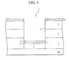
- a layer of resist 9is applied, patterned and developed and an opening 2 is etched in the third dielectric layer 3 and second dielectric layer 5 to provide an area for forming a damascene structure.
- An O 2 RIE etchis next used to define an opening in the first dielectric layer 7 down to conductive layer 1 . This processing sequence will remove the resist 9 as well.
- the resist layer 9 of FIG. 2has been removed and the opening 2 has been etched all the way down to conductive layer 1 .
- a plating layer 11is next deposited in the opening 2 as well as on top of the third dielectric layer 3 for the electroless deposition of the metal, preferably Cu.
- the plating layer 11further comprises a first barrier layer 10 and a seed layer 12 .
- the seed layer 12advantageously serves as a catalyst or base metal for subsequent electroless plating or electroplating of the metal and as an adhesion layer preventing delamination of subsequently electrolessly deposited or electroplated metal.
- any of various refractory metalscan be employed, such as tantalum, tungsten, molybdenum, hafnium, niobium, rhenium, osmium, ruthenium, zirconium, titanium, vanadium, chromium and manganese.
- a Cu seed layeris utilized if the metal conductor is copper.
- any of various refractory metalscan be employed, such as tantalum, tungsten, molybdenum, hafnium, niobium, rhenium, osmium, ruthenium, zirconium, titanium, vanadium, chromium and manganese. It has been found particularly advantageous to employ alloys of Ta or W with N or with certain polyimides, especially those formed from the ester of Zr, TI or Hf.
- the third dielectric layer 3is removed utilizing an etchant, such as hot phosphoric acid (H 3 PO 4 ) at a temperature of about 180° C. and at a etch rate of about 80 A/min., that has a negligible attack on the second dielectric layer 5 .
- an etchantsuch as hot phosphoric acid (H 3 PO 4 ) at a temperature of about 180° C. and at a etch rate of about 80 A/min.
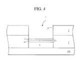
- a metal layer 13is next electrolessly plated in opening 2 to a thickness which causes the metal layer 13 to extend to about the level of the top surface of the first dielectric layer 7 .
- Electroless metal depositionis attractive due to low processing costs and high quality metal deposits.
- equipment for performing electroless metal depositionis relatively inexpensive compared to other semiconductor processing equipment for depositing metals.
- Electroless depositionalso offers the advantageous opportunity for batch processing of wafers, thereby further reducing the cost of electroless deposition and increasing production throughput.
- the surface of the metal layer 13is then implanted with dopant 15 to form a top barrier layer 13 a to prevent metal contamination.
- the dopant 15can be chosen from the group consisting of aluminum, boron, chromium, molybdenum, tungsten, titanium, zirconium, hafnium, magnesium, vanadium, columbium, tantalum or oxides or nitrides of these elements.
- the metalis copper and the dopant is zirconium.
- the zirconiumis implanted at an energy level of about 0.125 keV to 2.0 keV and at a dopant concentration of about 1.25 ⁇ 10 16 ions/cm 2 to 2.0 ⁇ 10 17 ions/cm2.
- the zirconiumis implanted at an energy of about 0.5 keV and at a concentration of about 5 ⁇ 10 16 ions/cm 2 .
- the implant energy and the concentrationcan be about 0.125 to about 2.0 keV and about 1.25 ⁇ 10 16 to about 2.0 ⁇ 10 17 ions/cm 2 , respectively without deviating significantly from the spirit of the invention.
- top barrier layer 13 ais about 5 A to 40 A thick and more preferably around 20 A thick.
- the second dielectric layer 5is next removed by an etchant, such as a mixture of hydroflouric acid (HF) and ammonium fluoride (NH 4 F) (1:8) at room temperature and at a rate of 700 A/min., which selectively removes the second dielectric layer 5 but not the first dielectric layer 7 , as illustrated in FIG. 6 .
- an etchantsuch as a mixture of hydroflouric acid (HF) and ammonium fluoride (NH 4 F) (1:8) at room temperature and at a rate of 700 A/min.
- HFhydroflouric acid
- NH 4 Fammonium fluoride
- any dopante.g. zirconium
- the resulting top barrier layer 13 acan be utilized in an interconnect system for an integrated circuit coupling passive and/or active components such as capacitors, transistors and various memory devices.
- a top barrier layer 13 ais formed over a metal layer 13 utilizing a sacrificial multilayer dielectric structure ( 3 , 5 ) and selective etching of the multilayer structure, plating layer 11 and top barrier layer 13 a to remove any unneeded portions.
- FIGS. 7-12A second embodiment of the invention is illustrated in FIGS. 7-12.
- first dielectric layer 19is deposited over conductive layer 1 in FIG. 7.
- a preferable first dielectric layeris a silicon dioxide.
- a second dielectric layer 17is deposited on top of the first dielectric layer 19 .
- the second dielectric layeris silicon nitride and is deposited to a thickness of about 500 A.
- a layer of resist 21is applied, patterned and developed and an opening 2 is etched in the second dielectric layer 17 and first dielectric layer 19 down to conductive layer 1 to form an opening to produce a damascene structure.
- the resist layer 21is maintained in place and a plating layer 23 is deposited in the opening 2 as well as on top of the resist layer 21 .
- the plating layer 23further comprises a first barrier layer 24 and a seed layer 26 .
- the seed layer 26advantageously serves as a catalyst or base metal for subsequent electroless plating or electroplating of the metal and as an adhesion layer preventing delamination of subsequently electrolessly deposited or electroplated metal.
- any of various refractory metalscan be employed, such as tantalum, tungsten, molybdenum, hafnium, niobium, rhenium, osmium, ruthenium, zirconium, titanium, vanadium, chromium and manganese.
- a Cu seed layeris utilized if the metal conductor is copper.
- any of various refractory metalscan be employed, such as tantalum, tungsten, molybdenum, hafnium, niobium, rhenium, osmium, ruthenium, zirconium, titanium, vanadium, chromium and manganese. It has been found particularly advantageous to employ alloys of Ta or W with N, when silicon dioxide is used as a insulator.
- the resist layer 21is next removed utilizing an etchant, such as a mixture of hydroflouric acid (HF) and ammonium fluoride (NH 4 F) (1:8) at room temperature and at a rate of 700 A/min., that has a negligible attack on the second dielectric layer 17 .
- an etchantsuch as a mixture of hydroflouric acid (HF) and ammonium fluoride (NH 4 F) (1:8) at room temperature and at a rate of 700 A/min.
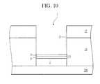
- a metal layer 13is electrolessly plated in opening 2 up to the thickness corresponding to approximately the level of the first dielectric layer 19 .
- the surface of the metalis then implanted with dopant 25 .
- the dopant 25can be chosen from the group consisting of aluminum, boron, chromium, molybdenum, tungsten, titanium, zirconium, hafnium, magnesium, vanadium, columbium, tantalum or oxides or nitrides of these elements.
- the metalis Cu and the dopant is TaN.
- the Tais implanted at a concentration of about 2.5 ⁇ 10 16 ions/cm 2 to 4 ⁇ 10 17 ions/cm 2 and an energy level of about 0.025 keV to 0.4 keV and N is implanted at a concentration of about 2 ⁇ 10 16 to 3.2 ⁇ 10 17 ions/cm 2 and an energy level of about 0.175 keV to 2.8 keV.
- the Tais implanted at a concentration of about 10 17 ions/cm 2 and energy level of about at 0.1 keV and the N implanted at a concentration of about 8 ⁇ 10 16 ions/cm 2 and an energy level of about 0.7 keV.
- the implant energy and the concentrationcan be about 0.125 to about 2.0 keV and about 1.25 ⁇ 10 16 to about 2.0 ⁇ 10 17 ions/cm 2 , respectively without deviating significantly from the spirit of the invention.
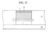
- the product of the Ta and N implantsforms a TaN barrier layer 13 b, shown in FIG. 12 .
- top barrier layer 13 ais bout 5 A to 40 A thick and more preferably about 20 A thick.
- the second dielectric layer 17is next removed by an etchant, such as hot phosphoric acid (H 3 PO 4 ) at a temperature of about 180° C. and at a etch rate of about 80 A/min., which selectively attacks the second dielectric layer and not the first dielectric layer as illustrated in FIG. 12 .
- H 3 PO 4hot phosphoric acid
- any TaN dopants which were implanted into the second dielectric layer 17are removed leaving first dielectric layer 19 free of impurities (i.e. TaN). Also, the remaining part of the plating layer 23 is removed along with the removal of the second dielectric layer 17 .
- the resulting top barrier layer 13 acan be utilized in an interconnect system for an integrated circuit coupling passive and/or active components such as capacitors, transistors and various memory devices.
- a top barrier layer 13 ais formed over a copper plug 13 utilizing a sacrificial multilayer dielectric structure and selective etching of the structure, plating layer and the top barrier layer to remove any unneeded portions.
- a top barrier layer for a metal conductoris formed in accordance with the invention without the need for CVD or CMP processing steps.
Landscapes
- Engineering & Computer Science (AREA)
- Physics & Mathematics (AREA)
- Condensed Matter Physics & Semiconductors (AREA)
- General Physics & Mathematics (AREA)
- Manufacturing & Machinery (AREA)
- Computer Hardware Design (AREA)
- Microelectronics & Electronic Packaging (AREA)
- Power Engineering (AREA)
- Internal Circuitry In Semiconductor Integrated Circuit Devices (AREA)
Abstract
Description
Claims (45)
Priority Applications (2)
| Application Number | Priority Date | Filing Date | Title |
|---|---|---|---|
| US09/534,224US6426289B1 (en) | 2000-03-24 | 2000-03-24 | Method of fabricating a barrier layer associated with a conductor layer in damascene structures |
| US10/137,293US6713875B2 (en) | 2000-03-24 | 2002-05-03 | Barrier layer associated with a conductor layer in damascene structures |
Applications Claiming Priority (1)
| Application Number | Priority Date | Filing Date | Title |
|---|---|---|---|
| US09/534,224US6426289B1 (en) | 2000-03-24 | 2000-03-24 | Method of fabricating a barrier layer associated with a conductor layer in damascene structures |
Related Child Applications (1)
| Application Number | Title | Priority Date | Filing Date |
|---|---|---|---|
| US10/137,293ContinuationUS6713875B2 (en) | 2000-03-24 | 2002-05-03 | Barrier layer associated with a conductor layer in damascene structures |
Publications (1)
| Publication Number | Publication Date |
|---|---|
| US6426289B1true US6426289B1 (en) | 2002-07-30 |
Family
ID=24129184
Family Applications (2)
| Application Number | Title | Priority Date | Filing Date |
|---|---|---|---|
| US09/534,224Expired - LifetimeUS6426289B1 (en) | 2000-03-24 | 2000-03-24 | Method of fabricating a barrier layer associated with a conductor layer in damascene structures |
| US10/137,293Expired - LifetimeUS6713875B2 (en) | 2000-03-24 | 2002-05-03 | Barrier layer associated with a conductor layer in damascene structures |
Family Applications After (1)
| Application Number | Title | Priority Date | Filing Date |
|---|---|---|---|
| US10/137,293Expired - LifetimeUS6713875B2 (en) | 2000-03-24 | 2002-05-03 | Barrier layer associated with a conductor layer in damascene structures |
Country Status (1)
| Country | Link |
|---|---|
| US (2) | US6426289B1 (en) |
Cited By (35)
| Publication number | Priority date | Publication date | Assignee | Title |
|---|---|---|---|---|
| US20020109233A1 (en)* | 2000-01-18 | 2002-08-15 | Micron Technology, Inc. | Process for providing seed layers for integrated circuit metallurgy |
| US6703308B1 (en)* | 2001-11-26 | 2004-03-09 | Advanced Micro Devices, Inc. | Method of inserting alloy elements to reduce copper diffusion and bulk diffusion |
| US6703309B1 (en)* | 2002-08-28 | 2004-03-09 | Micron Technology, Inc. | Method of reducing oxidation of metal structures using ion implantation, and device formed by such method |
| US6703307B2 (en) | 2001-11-26 | 2004-03-09 | Advanced Micro Devices, Inc. | Method of implantation after copper seed deposition |
| US20040056329A1 (en)* | 2002-09-25 | 2004-03-25 | Maiz Jose A. | Surface alteration of metal interconnect in integrated circuits for electromigration and adhesion improvement |
| US20040092095A1 (en)* | 2002-11-12 | 2004-05-13 | Applied Materials, Inc. | Side wall passivation films for damascene cu/low k electronic devices |
| US6740392B1 (en) | 2003-04-15 | 2004-05-25 | Micron Technology, Inc. | Surface barriers for copper and silver interconnects produced by a damascene process |
| US20040099932A1 (en)* | 2002-11-27 | 2004-05-27 | Motorola, Inc. | Thin GaAs die with copper back-metal structure |
| US6743716B2 (en) | 2000-01-18 | 2004-06-01 | Micron Technology, Inc. | Structures and methods to enhance copper metallization |
| US20040175845A1 (en)* | 2003-03-03 | 2004-09-09 | Molla Jaynal A. | Method of forming a flux concentrating layer of a magnetic device |
| US20040219788A1 (en)* | 2000-12-18 | 2004-11-04 | Marieb Thomas N. | Copper alloys for interconnections having improved electromigration characteristics and methods of making same |
| US20040235292A1 (en)* | 2003-05-20 | 2004-11-25 | Applied Materials, Inc. | Reduction of hillocks prior to dielectric barrier deposition in Cu damascene |
| US20040231795A1 (en)* | 2003-05-20 | 2004-11-25 | Applied Materials, Inc | Reduction of hillocks prior to dielectric barrier deposition in Cu damascene |
| US6835655B1 (en)* | 2001-11-26 | 2004-12-28 | Advanced Micro Devices, Inc. | Method of implanting copper barrier material to improve electrical performance |
| US6861349B1 (en) | 2002-05-15 | 2005-03-01 | Advanced Micro Devices, Inc. | Method of forming an adhesion layer with an element reactive with a barrier layer |
| US20050085073A1 (en)* | 2003-10-16 | 2005-04-21 | Advanced Micro Devices, Inc. | Method of using an adhesion precursor layer for chemical vapor deposition (CVD) copper deposition |
| US20050095855A1 (en)* | 2003-11-05 | 2005-05-05 | D'urso John J. | Compositions and methods for the electroless deposition of NiFe on a work piece |
| US20050208747A1 (en)* | 2004-03-18 | 2005-09-22 | Semiconductor Components Industries, Llc | Method of routing an electrical connection on a semiconductor device and structure therefor |
| US20060141779A1 (en)* | 2004-12-29 | 2006-06-29 | Dongbuanam Semiconductor Inc. | Method for forming an aluminum contact |
| US20060286797A1 (en)* | 2005-06-15 | 2006-12-21 | Chartered Semiconductor Manufacturing Ltd | Grain boundary blocking for stress migration and electromigration improvement in CU interconnects |
| US7205228B2 (en)* | 2003-06-03 | 2007-04-17 | Applied Materials, Inc. | Selective metal encapsulation schemes |
| US7220665B2 (en) | 2003-08-05 | 2007-05-22 | Micron Technology, Inc. | H2 plasma treatment |
| US7235884B1 (en)* | 2003-04-01 | 2007-06-26 | Altera Corporation | Local control of electrical and mechanical properties of copper interconnects to achieve stable and reliable via |
| US20070164439A1 (en)* | 2006-01-19 | 2007-07-19 | Taiwan Semiconductor Manufacturing Company, Ltd. | In-situ deposition for cu hillock suppression |
| US20080132057A1 (en)* | 2006-11-30 | 2008-06-05 | Frank Feustel | Method of selectively forming a conductive barrier layer by ald |
| US7402516B2 (en) | 2000-01-18 | 2008-07-22 | Micron Technology, Inc. | Method for making integrated circuits |
| US20090197408A1 (en)* | 2008-01-31 | 2009-08-06 | Matthias Lehr | Increasing electromigration resistance in an interconnect structure of a semiconductor device by forming an alloy |
| WO2010005866A1 (en)* | 2008-07-11 | 2010-01-14 | Sandisk 3D Llc | Method of making a nonvolatile memory device |
| US20100048018A1 (en)* | 2008-08-25 | 2010-02-25 | Varian Semiconductor Equipment Associates, Inc. | Doped Layers for Reducing Electromigration |
| US7670469B2 (en) | 2000-01-18 | 2010-03-02 | Micron Technology, Inc. | Methods and apparatus for making integrated-circuit wiring from copper, silver, gold, and other metals |
| US7696092B2 (en) | 2001-11-26 | 2010-04-13 | Globalfoundries Inc. | Method of using ternary copper alloy to obtain a low resistance and large grain size interconnect |
| US20120280392A1 (en)* | 2009-10-13 | 2012-11-08 | Franz Schrank | Semiconductor Component Havin a Plated Through-Hole and method for the Production Thereof |
| US8692376B2 (en) | 2011-05-06 | 2014-04-08 | Hynix Semiconductor Inc. | Semiconductor device and method of manufacturing the same |
| US20140332874A1 (en)* | 2012-04-13 | 2014-11-13 | Jeonggil Lee | Semiconductor devices |
| US9018108B2 (en) | 2013-01-25 | 2015-04-28 | Applied Materials, Inc. | Low shrinkage dielectric films |
Families Citing this family (9)
| Publication number | Priority date | Publication date | Assignee | Title |
|---|---|---|---|---|
| US6727177B1 (en)* | 2001-10-18 | 2004-04-27 | Lsi Logic Corporation | Multi-step process for forming a barrier film for use in copper layer formation |
| US6861758B2 (en)* | 2002-08-30 | 2005-03-01 | Intel Corporation | Structure and manufacturing process of localized shunt to reduce electromigration failure of copper dual damascene process |
| US6908851B2 (en)* | 2003-06-17 | 2005-06-21 | Texas Instruments Incorporated | Corrosion resistance for copper interconnects |
| US8552559B2 (en)* | 2004-07-29 | 2013-10-08 | Megica Corporation | Very thick metal interconnection scheme in IC chips |
| US8022552B2 (en)* | 2006-06-27 | 2011-09-20 | Megica Corporation | Integrated circuit and method for fabricating the same |
| KR100774651B1 (en) | 2006-07-21 | 2007-11-08 | 동부일렉트로닉스 주식회사 | Copper wiring formation method and structure of semiconductor device |
| US8193636B2 (en)* | 2007-03-13 | 2012-06-05 | Megica Corporation | Chip assembly with interconnection by metal bump |
| US20120141667A1 (en)* | 2010-07-16 | 2012-06-07 | Applied Materials, Inc. | Methods for forming barrier/seed layers for copper interconnect structures |
| KR20130114484A (en)* | 2012-04-09 | 2013-10-18 | 삼성전자주식회사 | A method of fabricating a semiconductor device |
Citations (7)
| Publication number | Priority date | Publication date | Assignee | Title |
|---|---|---|---|---|
| US5969422A (en)* | 1997-05-15 | 1999-10-19 | Advanced Micro Devices, Inc. | Plated copper interconnect structure |
| US6022808A (en)* | 1998-03-16 | 2000-02-08 | Advanced Micro Devices, Inc. | Copper interconnect methodology for enhanced electromigration resistance |
| US6111318A (en)* | 1997-01-21 | 2000-08-29 | Sony Corporation | Semiconductor device comprising Cu--Ta and method for forming the semiconductor device |
| US6110817A (en)* | 1999-08-19 | 2000-08-29 | Taiwan Semiconductor Manufacturing Company | Method for improvement of electromigration of copper by carbon doping |
| US6117770A (en)* | 1998-10-08 | 2000-09-12 | Advanced Micro Devices, Inc. | Method for implanting semiconductor conductive layers |
| US6146995A (en)* | 1997-10-17 | 2000-11-14 | Worldwide Semiconductor Manufacturing Corp. | Method for manufacturing interconnecting plug |
| US6147000A (en)* | 1998-08-11 | 2000-11-14 | Advanced Micro Devices, Inc. | Method for forming low dielectric passivation of copper interconnects |
Family Cites Families (8)
| Publication number | Priority date | Publication date | Assignee | Title |
|---|---|---|---|---|
| DE4400200C2 (en)* | 1993-01-05 | 1997-09-04 | Toshiba Kawasaki Kk | Semiconductor device with improved wiring structure and method of manufacturing the same |
| US5824599A (en)* | 1996-01-16 | 1998-10-20 | Cornell Research Foundation, Inc. | Protected encapsulation of catalytic layer for electroless copper interconnect |
| JP3285509B2 (en)* | 1997-03-18 | 2002-05-27 | 三菱電機株式会社 | Semiconductor device |
| US6249055B1 (en)* | 1998-02-03 | 2001-06-19 | Advanced Micro Devices, Inc. | Self-encapsulated copper metallization |
| US6172421B1 (en)* | 1998-08-11 | 2001-01-09 | Advanced Micro Devices, Inc. | Semiconductor device having an intermetallic layer on metal interconnects |
| JP3708732B2 (en)* | 1998-12-25 | 2005-10-19 | Necエレクトロニクス株式会社 | Manufacturing method of semiconductor device |
| US6100195A (en)* | 1998-12-28 | 2000-08-08 | Chartered Semiconductor Manu. Ltd. | Passivation of copper interconnect surfaces with a passivating metal layer |
| JP3907151B2 (en)* | 2000-01-25 | 2007-04-18 | 株式会社東芝 | Manufacturing method of semiconductor device |
- 2000
- 2000-03-24USUS09/534,224patent/US6426289B1/ennot_activeExpired - Lifetime
- 2002
- 2002-05-03USUS10/137,293patent/US6713875B2/ennot_activeExpired - Lifetime
Patent Citations (7)
| Publication number | Priority date | Publication date | Assignee | Title |
|---|---|---|---|---|
| US6111318A (en)* | 1997-01-21 | 2000-08-29 | Sony Corporation | Semiconductor device comprising Cu--Ta and method for forming the semiconductor device |
| US5969422A (en)* | 1997-05-15 | 1999-10-19 | Advanced Micro Devices, Inc. | Plated copper interconnect structure |
| US6146995A (en)* | 1997-10-17 | 2000-11-14 | Worldwide Semiconductor Manufacturing Corp. | Method for manufacturing interconnecting plug |
| US6022808A (en)* | 1998-03-16 | 2000-02-08 | Advanced Micro Devices, Inc. | Copper interconnect methodology for enhanced electromigration resistance |
| US6147000A (en)* | 1998-08-11 | 2000-11-14 | Advanced Micro Devices, Inc. | Method for forming low dielectric passivation of copper interconnects |
| US6117770A (en)* | 1998-10-08 | 2000-09-12 | Advanced Micro Devices, Inc. | Method for implanting semiconductor conductive layers |
| US6110817A (en)* | 1999-08-19 | 2000-08-29 | Taiwan Semiconductor Manufacturing Company | Method for improvement of electromigration of copper by carbon doping |
Cited By (71)
| Publication number | Priority date | Publication date | Assignee | Title |
|---|---|---|---|---|
| US7105914B2 (en) | 2000-01-18 | 2006-09-12 | Micron Technology, Inc. | Integrated circuit and seed layers |
| US7402516B2 (en) | 2000-01-18 | 2008-07-22 | Micron Technology, Inc. | Method for making integrated circuits |
| US8779596B2 (en) | 2000-01-18 | 2014-07-15 | Micron Technology, Inc. | Structures and methods to enhance copper metallization |
| US7378737B2 (en) | 2000-01-18 | 2008-05-27 | Micron Technology, Inc. | Structures and methods to enhance copper metallization |
| US7670469B2 (en) | 2000-01-18 | 2010-03-02 | Micron Technology, Inc. | Methods and apparatus for making integrated-circuit wiring from copper, silver, gold, and other metals |
| US7535103B2 (en) | 2000-01-18 | 2009-05-19 | Micron Technology, Inc. | Structures and methods to enhance copper metallization |
| US7301190B2 (en) | 2000-01-18 | 2007-11-27 | Micron Technology, Inc. | Structures and methods to enhance copper metallization |
| US7394157B2 (en) | 2000-01-18 | 2008-07-01 | Micron Technology, Inc. | Integrated circuit and seed layers |
| US7745934B2 (en) | 2000-01-18 | 2010-06-29 | Micron Technology, Inc. | Integrated circuit and seed layers |
| US20020109233A1 (en)* | 2000-01-18 | 2002-08-15 | Micron Technology, Inc. | Process for providing seed layers for integrated circuit metallurgy |
| US6743716B2 (en) | 2000-01-18 | 2004-06-01 | Micron Technology, Inc. | Structures and methods to enhance copper metallization |
| US20040219788A1 (en)* | 2000-12-18 | 2004-11-04 | Marieb Thomas N. | Copper alloys for interconnections having improved electromigration characteristics and methods of making same |
| US7220674B2 (en)* | 2000-12-18 | 2007-05-22 | Intel Corporation | Copper alloys for interconnections having improved electromigration characteristics and methods of making same |
| US20040224507A1 (en)* | 2000-12-18 | 2004-11-11 | Marieb Thomas N. | Copper alloys for interconnections having improved electromigration characteristics and methods of making same |
| US6703307B2 (en) | 2001-11-26 | 2004-03-09 | Advanced Micro Devices, Inc. | Method of implantation after copper seed deposition |
| US6835655B1 (en)* | 2001-11-26 | 2004-12-28 | Advanced Micro Devices, Inc. | Method of implanting copper barrier material to improve electrical performance |
| US6703308B1 (en)* | 2001-11-26 | 2004-03-09 | Advanced Micro Devices, Inc. | Method of inserting alloy elements to reduce copper diffusion and bulk diffusion |
| US7696092B2 (en) | 2001-11-26 | 2010-04-13 | Globalfoundries Inc. | Method of using ternary copper alloy to obtain a low resistance and large grain size interconnect |
| US6861349B1 (en) | 2002-05-15 | 2005-03-01 | Advanced Micro Devices, Inc. | Method of forming an adhesion layer with an element reactive with a barrier layer |
| US20040075173A1 (en)* | 2002-08-28 | 2004-04-22 | Micron Technology, Inc. | Method of reducing oxidation of metal structures using ion implantation, and device formed by such method |
| US6933232B2 (en)* | 2002-08-28 | 2005-08-23 | Micron Technology, Inc. | Method of reducing oxidation of metal structures by selectively implanting ions through a mask positioned above and not in contact with the substrate |
| US6703309B1 (en)* | 2002-08-28 | 2004-03-09 | Micron Technology, Inc. | Method of reducing oxidation of metal structures using ion implantation, and device formed by such method |
| US20040056329A1 (en)* | 2002-09-25 | 2004-03-25 | Maiz Jose A. | Surface alteration of metal interconnect in integrated circuits for electromigration and adhesion improvement |
| US6794755B2 (en) | 2002-09-25 | 2004-09-21 | Intel Corporation | Surface alteration of metal interconnect in integrated circuits for electromigration and adhesion improvement |
| US6878620B2 (en) | 2002-11-12 | 2005-04-12 | Applied Materials, Inc. | Side wall passivation films for damascene cu/low k electronic devices |
| US20040092095A1 (en)* | 2002-11-12 | 2004-05-13 | Applied Materials, Inc. | Side wall passivation films for damascene cu/low k electronic devices |
| WO2004044979A1 (en)* | 2002-11-12 | 2004-05-27 | Applied Materials, Inc. | Side wall passivation films for damascene cu/low k electronic devices |
| US20050127480A1 (en)* | 2002-11-27 | 2005-06-16 | Freescale Semiconductor, Inc. | Method for manufacturing thin gaas die with copper-back metal structures |
| US20040099932A1 (en)* | 2002-11-27 | 2004-05-27 | Motorola, Inc. | Thin GaAs die with copper back-metal structure |
| US7092890B2 (en)* | 2002-11-27 | 2006-08-15 | Freescale Semiconductor, Inc. | Method for manufacturing thin GaAs die with copper-back metal structures |
| US6870243B2 (en)* | 2002-11-27 | 2005-03-22 | Freescale Semiconductor, Inc. | Thin GaAs die with copper back-metal structure |
| US20040175845A1 (en)* | 2003-03-03 | 2004-09-09 | Molla Jaynal A. | Method of forming a flux concentrating layer of a magnetic device |
| WO2004079742A3 (en)* | 2003-03-03 | 2005-03-17 | Freescale Semiconductor Inc | Method of forming a flux concentrating layer of a magnetic device |
| US7235884B1 (en)* | 2003-04-01 | 2007-06-26 | Altera Corporation | Local control of electrical and mechanical properties of copper interconnects to achieve stable and reliable via |
| US20040209456A1 (en)* | 2003-04-15 | 2004-10-21 | Farrar Paul A. | Surface barriers for copper and silver interconnects produced by a damascene process |
| US7229924B2 (en) | 2003-04-15 | 2007-06-12 | Micron Technology, Inc. | Surface barriers for copper and silver interconnects produced by a damascene process |
| US6740392B1 (en) | 2003-04-15 | 2004-05-25 | Micron Technology, Inc. | Surface barriers for copper and silver interconnects produced by a damascene process |
| US20040235292A1 (en)* | 2003-05-20 | 2004-11-25 | Applied Materials, Inc. | Reduction of hillocks prior to dielectric barrier deposition in Cu damascene |
| US7723228B2 (en) | 2003-05-20 | 2010-05-25 | Applied Materials, Inc. | Reduction of hillocks prior to dielectric barrier deposition in Cu damascene |
| US20040231795A1 (en)* | 2003-05-20 | 2004-11-25 | Applied Materials, Inc | Reduction of hillocks prior to dielectric barrier deposition in Cu damascene |
| US20080075888A1 (en)* | 2003-05-20 | 2008-03-27 | Applied Materials, Inc. | Reduction of hillocks prior to dielectric barrier deposition in cu damascene |
| US7371427B2 (en) | 2003-05-20 | 2008-05-13 | Applied Materials, Inc. | Reduction of hillocks prior to dielectric barrier deposition in Cu damascene |
| US7205228B2 (en)* | 2003-06-03 | 2007-04-17 | Applied Materials, Inc. | Selective metal encapsulation schemes |
| US7220665B2 (en) | 2003-08-05 | 2007-05-22 | Micron Technology, Inc. | H2 plasma treatment |
| US7504674B2 (en) | 2003-08-05 | 2009-03-17 | Micron Technology, Inc. | Electronic apparatus having a core conductive structure within an insulating layer |
| US20050085073A1 (en)* | 2003-10-16 | 2005-04-21 | Advanced Micro Devices, Inc. | Method of using an adhesion precursor layer for chemical vapor deposition (CVD) copper deposition |
| US7169706B2 (en) | 2003-10-16 | 2007-01-30 | Advanced Micro Devices, Inc. | Method of using an adhesion precursor layer for chemical vapor deposition (CVD) copper deposition |
| US20050095855A1 (en)* | 2003-11-05 | 2005-05-05 | D'urso John J. | Compositions and methods for the electroless deposition of NiFe on a work piece |
| US7138327B2 (en)* | 2004-03-18 | 2006-11-21 | Semiconductor Components Industries, Llc | Method of routing an electrical connection on a semiconductor device and structure therefor |
| US20050208747A1 (en)* | 2004-03-18 | 2005-09-22 | Semiconductor Components Industries, Llc | Method of routing an electrical connection on a semiconductor device and structure therefor |
| US7407884B2 (en)* | 2004-12-29 | 2008-08-05 | Dongbu Electronics Co., Ltd. | Method for forming an aluminum contact |
| US20060141779A1 (en)* | 2004-12-29 | 2006-06-29 | Dongbuanam Semiconductor Inc. | Method for forming an aluminum contact |
| US20060286797A1 (en)* | 2005-06-15 | 2006-12-21 | Chartered Semiconductor Manufacturing Ltd | Grain boundary blocking for stress migration and electromigration improvement in CU interconnects |
| US7989338B2 (en) | 2005-06-15 | 2011-08-02 | Globalfoundries Singapore Pte. Ltd. | Grain boundary blocking for stress migration and electromigration improvement in CU interconnects |
| US7423347B2 (en)* | 2006-01-19 | 2008-09-09 | Taiwan Semiconductor Manufacturing Company, Ltd. | In-situ deposition for cu hillock suppression |
| US7659198B2 (en) | 2006-01-19 | 2010-02-09 | Taiwan Semiconductor Manufacturing Company, Ltd. | In-situ deposition for Cu hillock suppression |
| US20070164439A1 (en)* | 2006-01-19 | 2007-07-19 | Taiwan Semiconductor Manufacturing Company, Ltd. | In-situ deposition for cu hillock suppression |
| US8173538B2 (en)* | 2006-11-30 | 2012-05-08 | Advanced Micro Devices, Inc. | Method of selectively forming a conductive barrier layer by ALD |
| US20080132057A1 (en)* | 2006-11-30 | 2008-06-05 | Frank Feustel | Method of selectively forming a conductive barrier layer by ald |
| US20090197408A1 (en)* | 2008-01-31 | 2009-08-06 | Matthias Lehr | Increasing electromigration resistance in an interconnect structure of a semiconductor device by forming an alloy |
| US20110124189A1 (en)* | 2008-01-31 | 2011-05-26 | Globalfoundries Inc. | Increasing Electromigration Resistance in an Interconnect Structure of a Semiconductor Device by Forming an Alloy |
| DE102008007001A1 (en)* | 2008-01-31 | 2009-08-06 | Advanced Micro Devices, Inc., Sunnyvale | Increasing the resistance to electromigration in a connection structure of a semiconductor device by forming an alloy |
| US8329577B2 (en) | 2008-01-31 | 2012-12-11 | Globalfoundries Inc. | Method of forming an alloy in an interconnect structure to increase electromigration resistance |
| DE102008007001B4 (en)* | 2008-01-31 | 2016-09-22 | Globalfoundries Dresden Module One Limited Liability Company & Co. Kg | Increasing the resistance to electromigration in a connection structure of a semiconductor device by forming an alloy |
| WO2010005866A1 (en)* | 2008-07-11 | 2010-01-14 | Sandisk 3D Llc | Method of making a nonvolatile memory device |
| US20100048018A1 (en)* | 2008-08-25 | 2010-02-25 | Varian Semiconductor Equipment Associates, Inc. | Doped Layers for Reducing Electromigration |
| US20120280392A1 (en)* | 2009-10-13 | 2012-11-08 | Franz Schrank | Semiconductor Component Havin a Plated Through-Hole and method for the Production Thereof |
| US8531041B2 (en)* | 2009-10-13 | 2013-09-10 | Ams Ag | Semiconductor component having a plated through-hole and method for the production thereof |
| US8692376B2 (en) | 2011-05-06 | 2014-04-08 | Hynix Semiconductor Inc. | Semiconductor device and method of manufacturing the same |
| US20140332874A1 (en)* | 2012-04-13 | 2014-11-13 | Jeonggil Lee | Semiconductor devices |
| US9018108B2 (en) | 2013-01-25 | 2015-04-28 | Applied Materials, Inc. | Low shrinkage dielectric films |
Also Published As
| Publication number | Publication date |
|---|---|
| US6713875B2 (en) | 2004-03-30 |
| US20020132476A1 (en) | 2002-09-19 |
Similar Documents
| Publication | Publication Date | Title |
|---|---|---|
| US6426289B1 (en) | Method of fabricating a barrier layer associated with a conductor layer in damascene structures | |
| US6359328B1 (en) | Methods for making interconnects and diffusion barriers in integrated circuits | |
| US6821879B2 (en) | Copper interconnect by immersion/electroless plating in dual damascene process | |
| US6509267B1 (en) | Method of forming low resistance barrier on low k interconnect with electrolessly plated copper seed layer | |
| US7132363B2 (en) | Stabilizing fluorine etching of low-k materials | |
| US20170263721A1 (en) | Copper-filled trench contact for transistor performance improvement | |
| US7417321B2 (en) | Via structure and process for forming the same | |
| US7319071B2 (en) | Methods for forming a metallic damascene structure | |
| US20020089063A1 (en) | Copper dual damascene interconnect technology | |
| US20040219783A1 (en) | Copper dual damascene interconnect technology | |
| US9334572B2 (en) | Interconnect structure and method of making same | |
| US20020167089A1 (en) | Copper dual damascene interconnect technology | |
| KR20040003232A (en) | Method for manufacturing a multi metal line in semiconductor device | |
| EP0504984B1 (en) | Method of making a connection on a semiconductor device | |
| US6610594B2 (en) | Locally increasing sidewall density by ion implantation | |
| SG188903A1 (en) | Discontinuous/non-uniform metal cap structure and process for interconnect integration | |
| KR100338941B1 (en) | Contact forming method for semiconductor device | |
| KR100301248B1 (en) | Method of forming a metal wiring in a semiconductor device | |
| KR100939773B1 (en) | Metal wiring of semiconductor device and forming method thereof | |
| US9812391B2 (en) | Advanced metallization for damage repair | |
| US6656834B1 (en) | Method of selectively alloying interconnect regions by deposition process | |
| US7309651B2 (en) | Method for improving reliability of copper interconnects | |
| KR100701673B1 (en) | Copper wiring formation method of semiconductor device | |
| KR20020000461A (en) | A method of forming a metal line in a semiconductor device | |
| KR101127025B1 (en) | Method for Forming Copper Line of Semiconductor Device |
Legal Events
| Date | Code | Title | Description |
|---|---|---|---|
| AS | Assignment | Owner name:MICRON TECHNOLOGY, INC., IOWA Free format text:ASSIGNMENT OF ASSIGNORS INTEREST;ASSIGNOR:FARRAR, PAUL A.;REEL/FRAME:010649/0069 Effective date:20000316 | |
| STCF | Information on status: patent grant | Free format text:PATENTED CASE | |
| FPAY | Fee payment | Year of fee payment:4 | |
| FEPP | Fee payment procedure | Free format text:PAYER NUMBER DE-ASSIGNED (ORIGINAL EVENT CODE: RMPN); ENTITY STATUS OF PATENT OWNER: LARGE ENTITY Free format text:PAYOR NUMBER ASSIGNED (ORIGINAL EVENT CODE: ASPN); ENTITY STATUS OF PATENT OWNER: LARGE ENTITY | |
| FPAY | Fee payment | Year of fee payment:8 | |
| FPAY | Fee payment | Year of fee payment:12 | |
| AS | Assignment | Owner name:U.S. BANK NATIONAL ASSOCIATION, AS COLLATERAL AGENT, CALIFORNIA Free format text:SECURITY INTEREST;ASSIGNOR:MICRON TECHNOLOGY, INC.;REEL/FRAME:038669/0001 Effective date:20160426 Owner name:U.S. BANK NATIONAL ASSOCIATION, AS COLLATERAL AGEN Free format text:SECURITY INTEREST;ASSIGNOR:MICRON TECHNOLOGY, INC.;REEL/FRAME:038669/0001 Effective date:20160426 | |
| AS | Assignment | Owner name:MORGAN STANLEY SENIOR FUNDING, INC., AS COLLATERAL AGENT, MARYLAND Free format text:PATENT SECURITY AGREEMENT;ASSIGNOR:MICRON TECHNOLOGY, INC.;REEL/FRAME:038954/0001 Effective date:20160426 Owner name:MORGAN STANLEY SENIOR FUNDING, INC., AS COLLATERAL Free format text:PATENT SECURITY AGREEMENT;ASSIGNOR:MICRON TECHNOLOGY, INC.;REEL/FRAME:038954/0001 Effective date:20160426 | |
| AS | Assignment | Owner name:U.S. BANK NATIONAL ASSOCIATION, AS COLLATERAL AGENT, CALIFORNIA Free format text:CORRECTIVE ASSIGNMENT TO CORRECT THE REPLACE ERRONEOUSLY FILED PATENT #7358718 WITH THE CORRECT PATENT #7358178 PREVIOUSLY RECORDED ON REEL 038669 FRAME 0001. ASSIGNOR(S) HEREBY CONFIRMS THE SECURITY INTEREST;ASSIGNOR:MICRON TECHNOLOGY, INC.;REEL/FRAME:043079/0001 Effective date:20160426 Owner name:U.S. BANK NATIONAL ASSOCIATION, AS COLLATERAL AGEN Free format text:CORRECTIVE ASSIGNMENT TO CORRECT THE REPLACE ERRONEOUSLY FILED PATENT #7358718 WITH THE CORRECT PATENT #7358178 PREVIOUSLY RECORDED ON REEL 038669 FRAME 0001. ASSIGNOR(S) HEREBY CONFIRMS THE SECURITY INTEREST;ASSIGNOR:MICRON TECHNOLOGY, INC.;REEL/FRAME:043079/0001 Effective date:20160426 | |
| AS | Assignment | Owner name:JPMORGAN CHASE BANK, N.A., AS COLLATERAL AGENT, ILLINOIS Free format text:SECURITY INTEREST;ASSIGNORS:MICRON TECHNOLOGY, INC.;MICRON SEMICONDUCTOR PRODUCTS, INC.;REEL/FRAME:047540/0001 Effective date:20180703 Owner name:JPMORGAN CHASE BANK, N.A., AS COLLATERAL AGENT, IL Free format text:SECURITY INTEREST;ASSIGNORS:MICRON TECHNOLOGY, INC.;MICRON SEMICONDUCTOR PRODUCTS, INC.;REEL/FRAME:047540/0001 Effective date:20180703 | |
| AS | Assignment | Owner name:MICRON TECHNOLOGY, INC., IDAHO Free format text:RELEASE BY SECURED PARTY;ASSIGNOR:U.S. BANK NATIONAL ASSOCIATION, AS COLLATERAL AGENT;REEL/FRAME:047243/0001 Effective date:20180629 | |
| AS | Assignment | Owner name:MICRON TECHNOLOGY, INC., IDAHO Free format text:RELEASE BY SECURED PARTY;ASSIGNOR:MORGAN STANLEY SENIOR FUNDING, INC., AS COLLATERAL AGENT;REEL/FRAME:050937/0001 Effective date:20190731 | |
| AS | Assignment | Owner name:MICRON SEMICONDUCTOR PRODUCTS, INC., IDAHO Free format text:RELEASE BY SECURED PARTY;ASSIGNOR:JPMORGAN CHASE BANK, N.A., AS COLLATERAL AGENT;REEL/FRAME:051028/0001 Effective date:20190731 Owner name:MICRON TECHNOLOGY, INC., IDAHO Free format text:RELEASE BY SECURED PARTY;ASSIGNOR:JPMORGAN CHASE BANK, N.A., AS COLLATERAL AGENT;REEL/FRAME:051028/0001 Effective date:20190731 |