US6426027B1 - Method of injection molding for creating a fluid meter housing - Google Patents
Method of injection molding for creating a fluid meter housingDownload PDFInfo
- Publication number
- US6426027B1 US6426027B1US09/572,467US57246700AUS6426027B1US 6426027 B1US6426027 B1US 6426027B1US 57246700 AUS57246700 AUS 57246700AUS 6426027 B1US6426027 B1US 6426027B1
- Authority
- US
- United States
- Prior art keywords
- fluid meter
- meter housing
- mold
- metal
- molten
- Prior art date
- Legal status (The legal status is an assumption and is not a legal conclusion. Google has not performed a legal analysis and makes no representation as to the accuracy of the status listed.)
- Expired - Lifetime
Links
Images


Classifications
- B—PERFORMING OPERATIONS; TRANSPORTING
- B29—WORKING OF PLASTICS; WORKING OF SUBSTANCES IN A PLASTIC STATE IN GENERAL
- B29C—SHAPING OR JOINING OF PLASTICS; SHAPING OF MATERIAL IN A PLASTIC STATE, NOT OTHERWISE PROVIDED FOR; AFTER-TREATMENT OF THE SHAPED PRODUCTS, e.g. REPAIRING
- B29C45/00—Injection moulding, i.e. forcing the required volume of moulding material through a nozzle into a closed mould; Apparatus therefor
- B29C45/17—Component parts, details or accessories; Auxiliary operations
- B29C45/40—Removing or ejecting moulded articles
- B29C45/44—Removing or ejecting moulded articles for undercut articles
- B29C45/4457—Removing or ejecting moulded articles for undercut articles using fusible, soluble or destructible cores
- B—PERFORMING OPERATIONS; TRANSPORTING
- B29—WORKING OF PLASTICS; WORKING OF SUBSTANCES IN A PLASTIC STATE IN GENERAL
- B29C—SHAPING OR JOINING OF PLASTICS; SHAPING OF MATERIAL IN A PLASTIC STATE, NOT OTHERWISE PROVIDED FOR; AFTER-TREATMENT OF THE SHAPED PRODUCTS, e.g. REPAIRING
- B29C45/00—Injection moulding, i.e. forcing the required volume of moulding material through a nozzle into a closed mould; Apparatus therefor
- B29C45/16—Making multilayered or multicoloured articles
- B29C2045/1696—Making multilayered or multicoloured articles injecting metallic layers and plastic material layers
- B—PERFORMING OPERATIONS; TRANSPORTING
- B29—WORKING OF PLASTICS; WORKING OF SUBSTANCES IN A PLASTIC STATE IN GENERAL
- B29C—SHAPING OR JOINING OF PLASTICS; SHAPING OF MATERIAL IN A PLASTIC STATE, NOT OTHERWISE PROVIDED FOR; AFTER-TREATMENT OF THE SHAPED PRODUCTS, e.g. REPAIRING
- B29C45/00—Injection moulding, i.e. forcing the required volume of moulding material through a nozzle into a closed mould; Apparatus therefor
- B29C45/17—Component parts, details or accessories; Auxiliary operations
- B29C45/40—Removing or ejecting moulded articles
- B29C45/44—Removing or ejecting moulded articles for undercut articles
- B29C45/4457—Removing or ejecting moulded articles for undercut articles using fusible, soluble or destructible cores
- B29C2045/4464—Removing or ejecting moulded articles for undercut articles using fusible, soluble or destructible cores injecting the core and the undercut article in separate cavities
Definitions
- the present inventionrelates to a method of creating a fluid meter housing. More specifically, the present invention provides a method of manufacturing the housing for a fluid meter in which a molten material is injected into a cavity formed between a core and a mold. The core and mold are configured so that the cavity is shaped as desired for the fluid meter housing. After allowing the molten material to harden, the housing and enclosed core are removed from the mold. The core is then heated to its melting point and drained from within the fluid meter housing.
- Fluid metershave traditionally been constructed from various metals such as bronze and copper. As new materials and methods of using them have developed, the economic feasibility of substituting such materials for metals in the construction of fluid meters has improved.
- Thermoplasticsrepresent one such class of material that can not only result in savings in the cost of materials but can also be more suitable for use with certain fluids.
- plastic partshave been molded using conventional plastic injection molding techniques. Such techniques generally involve creating a mold having an internal cavity into which the plastic is injected in a molten state. Upon cooling the mold, the resulting plastic part may be removed by extraction or by opening the mold. Such techniques have been streamlined for mass production of plastic parts ranging from computer connectors to automobile components.
- Fluid metersgenerally have complex internal passage ways complicating the use of conventional plastic injection molding techniques to manufacture housings or casings for fluid meters. While it is possible to manufacture such housings using conventional molding techniques, this proves to be time consuming and labor intensive.
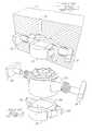
- FIG. 1depicts a cross-section of an exemplary mold 20 used with conventional plastic injection molding techniques.
- Mold 20includes a cavity defined in part by internal walls 22 which correspond in shape to the external surface of a desired fluid meter housing.
- Multiple interconnected inserts 24shown in FIG. 2, are placed within the cavity and correspond in shape to the internal surface of the fluid meter housing 26 .
- Interconnected inserts 24are typically constructed from a metal, such as stainless steel, having a relatively high melting point. Using the specifications of the fluid meter housing 26 sought to be formed, interconnected inserts 24 are carefully machined so that when assembled the external surface of the interconnected inserts 24 conforms to the internal surface of the fluid meter housing 26 . Together, inserts 24 and internal walls 22 configure the shape of the cavity to correspond to the shape of housing 26 .
- mold 20Upon placing interconnecting inserts 24 into the cavity, mold 20 is closed under a press capable of applying forces of up to 150 tons to maintain closure of the mold 20 . While closed, a molten thermoplastic material is injected at high pressures through port 28 . A sufficient amount of material must be injected to fill the cavity that exists between walls 22 of mold 20 and the external surface of interconnected inserts 24 . As the molten thermoplastic material begins to cool, it also begins to solidify and assume the shape of the fluid meter housing 26 . Simultaneously, the thermoplastic material also begins to shrink. As a result, mold 20 must be quickly reopened so that fluid meter housing 26 , now containing interconnecting inserts 24 , can be removed. Interconnecting inserts 24 are then removed from the interior of housing 26 . If the removal of interconnecting inserts 24 is not performed quickly after the thermoplastic material begins to cool, the interconnecting inserts 24 will be trapped inside the fluid meter housing 26 .
- the present inventionprovides a method of manufacturing a housing or casing for a fluid meter.
- the method of the present inventionprovides for injecting a molten material into a cavity or space formed between a core and a mold.
- the core and moldare configured such that the cavity between the surfaces of the core and mold forms the shape of the desired fluid meter housing.
- the housing and the enclosed coreare removed from the mold.
- the coreis then heated to its melting point, or otherwise liquified, and drained or removed from inside the fluid meter housing.
- the present inventionovercomes disadvantages of the prior art by providing a process whereby a fluid meter housing having relatively complex internal characteristics may be manufactured without the necessity of using expensive inserts or having to rapidly disassemble such inserts at high temperatures.
- a first moldhaving an internal surface that corresponds to the desired internal shape for a fluid meter housing.
- a metal in a molten stateis injected into this first mold.
- the molten metalis then cooled until the metal solidifies to form a metal core in the shape of the internal surface of the fluid meter housing. After cooling, the resulting metal core is removed from the first mold.
- a second moldis a provided having an internal surface that corresponds to the external shape desired for the fluid meter housing.
- This second mold and the coreare configured so that upon placing the core into the second mold, a cavity is created that corresponds to the shape of the desired fluid meter housing.
- a molten thermoplastic materialis injected into the cavity so as to fill the cavity and form the fluid meter housing between the metal core and the second mold.
- the second mold and thermoplastic materialare then cooled to cause the thermoplastic material to solidify into the shape of the fluid meter housing.
- the resulting fluid meter housingis then removed from the second mold. At this point in the process, the fluid meter housing may still contain the metal core.
- the metal coreis heated until the metal reaches a molten state and can then be removed from the fluid meter housing.
- the metal coremay be removed while the fluid meter housing is still within the second mold. This alternative requires that the materials used to construct the molds and housing have appropriate relative melting point temperatures.
- the first and second moldcan be configured with a variety of features desired for the fluid meter housing.
- the first and second moldsmay be configured for defining a fluid inlet and a fluid outlet for the housing.
- the first and second moldsmay also be configured for providing a plurality of tabs and a locking boss on the surface of the housing such that a register or other device may be attached.
- the first and second moldsmay also be configured such that the fluid meter housing is provided with resealable threaded connectors at the fluid inlet and the fluid outlet for connecting the housing to conduit or to the path of flow.
- a metalis heated until reaching a molten state.
- a first dieis provided having an internal surface that is shaped identically to the internal surface of a desired fluid meter housing.
- the molten metalis inserted into the first die and then the temperature of the molten metal is lowered until the metal becomes capable of sustaining shape. This shape will correspond to the internal surface of the first die and therefore the internal surface of the fluid meter housing.
- the resulting metal shapeis removed from the first die.
- a second diehaving an internal surface shaped to form the external surface of the fluid meter housing being manufactured.
- This second dieis also configured for forming a cavity between the internal surface of the second die and the metal shape that corresponds to the geometry and thickness of the fluid meter housing.
- the cavityis created upon placing the metal shape into the second die.
- Molten plasticis then inserted into the cavity between the metal shape and the second die. After insertion, the molten plastic is cooled until it becomes rigid enough to retain the shape of the cavity and thereby form the fluid meter housing.
- the metal shape and housingare removed from the second die.
- the temperature of the metal shapeis then raised until the metal becomes molten, thereby allowing the metal to be removed from the interior of the fluid meter housing.
- a first materialhaving a melting temperature of T 1 .
- a coreis formed having the desired geometry to form the internal shape of a fluid meter casing.
- a shellis provided having an internal surface that corresponds to the external shape of the fluid meter casing.
- the coreis located inside the shell so as to provide a space between the core and the shell that corresponds to the shape and dimensions of the fluid meter casing.
- a second materialis also provided having a melting temperature of T 2 .
- Melting temperature T 2 of the second materialmust be greater than the melting temperature T 1 of the first material.
- the second materialis injected in a molten state into the space formed between the core and the shell.
- the second materialis allowed to cool to a temperature less than T 2 so that the second material will solidify and form into the shape of the fluid meter casing.
- the fluid meter casingnow contains the first material and may be removed from the shell.
- the first materialis then heated to a temperature greater than T 1 but less than T 2 . As a consequence, the first material will melt without melting the second material that forms the fluid meter casing.
- the first materialmay thereby be removed from the interior of the fluid meter casing.
- a meltable insertis positioned within a mold.
- the insert and the moldare both configured so as to create a void between the adjacent surfaces of the insert and the mold that is equivalent in shape and thickness to a fluid meter housing.
- a materialis then introduced in a fluid state into the void so as to substantially fill the void.
- the temperature of the materialis then reduced until the material becomes sufficiently rigid to maintain the shape of the fluid meter housing formed by the void.
- the fluid meter housingmay then be removed from the mold. At this point in process, the fluid meter housing may still contain the insert.
- the insertis then heated until a temperature is reached at which the insert flows out of the fluid meter housing. This step may also be formed while the fluid meter is still within the mold if appropriate materials are selected for creating the insert, mold, and fluid meter housing.
- a modulethat corresponds to the internal shape of a casing for fluid meter.
- This moduleis constructed from a material that is meltable.
- a chamberis provided having an internal surface that corresponds to the external surface of the casing.
- the moduleis placed into the chamber so as to create a volume that corresponds to the shape and thickness of the casing.
- the resulting volumeis then filled with a liquid.
- the liquidis then caused to harden and thereby assume the shape of the volume and form the desired casing.
- the moduleis then melted so as to enable the module to be removed from the casing.
- the casingmay then be removed from the chamber.
- the casingmay be removed from the chamber while still containing the module; and then the module may be melted so as to enable it to be removed from the casing.
- thermoplastic materialfor the construction of the meter housing
- the present inventionis not limited to such thermoplastic materials. Any material capable of being injected into the cavity and having a melting point higher than the melting point of the material used for the core may be utilized.
- the coremay be constructed from any material that will not chemically or physically react with the material selected for the fluid meter housing and is not limited to a metal alloy. However, the core must be constructed from a material having a melting point lower than the melting point of the material selected for the fluid meter housing if heat or elevated temperature is used to remove the core from the housing.
- FIG. 1is a cross-sectional and perspective view depicting a prior art technique.
- FIG. 2is a partial and exploded perspective view depicting a prior art technique.
- FIG. 3is a perspective view of a shape of an exemplary conventional fluid meter housing, such as may be produced with practice of the present invention.
- FIG. 4is a partial cross-sectional view of an exemplary mold for a core.
- FIG. 5is a cross-sectional view of an exemplary mold for the fluid meter housing.
- FIG. 6is a partial cross-sectional view of an exemplary core inserted into an exemplary mold for the fluid meter housing, in accordance with the subject invention.
- FIG. 7is a partial cross-sectional view of an exemplary mold after formation of the fluid meter housing, in accordance with the subject invention.
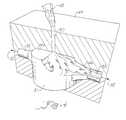
- FIG. 8is a perspective view showing removal of such exemplary core from the fluid meter housing, in accordance with the subject invention.
- Housing 30may include a fluid inlet 32 and a fluid outlet 34 . Resealable, threaded connectors 36 and 38 may be provided for selectively connected housing 30 into a fluid supply. Housing 30 also may include a locking boss 40 and a plurality of tabs 42 for connecting a chamber or register to housing 30 to operate in conjunction therewith.
- a variety of internal componentsmay be contained within housing 30 depending upon the identity of the fluid being measured and the type of fluid measurements being undertaken. The present invention relates to a process for the manufacture of the housing 30 and therefore these internal components are not depicted.
- First mold 44for use in one example of the present invention is shown in FIG. 4 .
- First mold 44is constructed to have an internal surface 46 that corresponds to the internal shape desired for housing 30 . By varying the contour of internal surface 46 , the internal characteristics of housing 30 can be determined.
- first mold 44includes conduits 33 and 35 which will form the fluid inlet 32 and the fluid outlet 34 .
- FIG. 4depicts this step of the process and demonstrates the interior of first mold 44 being filled with first material 48 .
- first material 48is allowed or caused to solidify or harden. This step does not require an actual phase change in the traditional sense from liquid to solid but instead requires only that first material 48 changes into a condition where it is capable of assuming and maintaining the shape of first mold 44 upon being removed from first mold 44 .
- first material 48An example of a material that could be used for first material 48 would be a metal or a metal alloy. Accordingly, to prepare such a metal for introduction into the first mold 44 , the metal would be heated until reaching a molten or liquid condition so that it can be poured, injected, inserted, or otherwise introduced into first mold 44 . Upon filling the interior of first mold 44 , first material 48 (i.e. the molten metal) is cooled until it hardens sufficiently to retain the internal shape of first mold 44 . This step may be accomplished by simply subjecting first mold 44 to a reduced temperature, thereby allowing first material 48 to cool through conduction. The hardening of first material 48 forms an insert, module, or core 51 in the shape of the internal surface 46 of first mold 44 that may then be removed from first mold 44 . As shown in FIG. 4, first mold 44 may be opened along seam 52 to enable removal of core 51 .
- a second mold 54is used in accordance with this example of the present invention to create the external surface of fluid meter housing 30 .
- Second mold 54may also be referred to as a shell, die, or chamber.
- the internal surface 56 of second mold 54is configured to provide the shape and desired features for the external surface of housing 30 .
- threads 58 and 60will provide the external housing with resealable, threaded connectors 36 and 38 .
- Indents 62 and 64shown in cross-section in FIG. 5, provide a plurality of tabs 42 for housing 30 .
- Recess 66also shown in cross-section, provides for the formation of locking boss 40 .
- core 51is placed or located into second mold 54 in accordance with the invention.
- second mold 54is shown in cross-section while core 51 is depicted in full relief.
- a volume or space or cavity 68is created.
- the geometry, shape, thickness, and dimensions of cavity 68 in accordance with the inventioncorresponds to or is substantially identical to the geometry, shape, thickness, and dimensions of the desired fluid meter housing 30 .
- the external surface of core 51 and the internal surface of second mold 54are configured or shaped to so create cavity 68 .
- a second material 71is injected or inserted or introduced into cavity 68 .
- second material 71is allowed or caused to harden or solidify. This step does not require an actual phase change in the traditional sense from liquid to solid but instead requires that second material 71 change into a condition where it will assume and maintain the shape of cavity 68 formed between core 51 and second mold 54 .
- thermoplasticsthermosets, or epoxies. Accordingly, a thermoplastic would be heated to a molten or liquid-like state and then poured, injected, inserted, or otherwise introduced into cavity 68 through part 70 . Upon filling cavity 68 , the thermoplastic (second material 71 ) is cooled until it hardens sufficiently to substantially retain the shape of cavity 68 . This cooling step may be accomplished by subjecting second mold 54 to a reduced temperature and allow conduction to cool the second material 71 .
- second material 71forms the desired fluid meter housing 30 as shown in FIG. 7 (second mold 54 is shown in cross-section while housing 30 is shown in full relief).
- the hardened second material 71also occupies port 70 to form a stem 74 that may be removed from housing 30 and discarded.
- the resulting housing 30may be removed from mold 54 by separating mold 54 along seam 72 .
- the removal of housing 30also results in the removal of core 51 that is now enclosed or encompassed within housing 30 . Accordingly, core 51 is now removed from the interior of housing 30 .
- FIG. 8depicts one example of how core 51 may be removed in accordance with the subject invention from the interior of housing 30 .
- a bath 76is provided containing a hot oil 78 .
- Housing 30 and core 51are immersed into oil 78 .
- the temperature of oil 78is raised to a point where the material forming core 51 melts and leaks or flows out of housing 30 (which is shown in partial cross-section to allow depiction of the melting of core 51 ).
- the material of core 51falls to the bottom of bath 76 where it may be collected and recycled in the inventive process.
- FIG. 8depicts only one example of the removal of core 51 from housing 30 .
- core 51may be drained from the interior of housing 30 before removing either core 51 or housing 30 from second mold 54 .
- Such a stepmay be accomplished by heating core 51 to its melting point while maintaining a temperature below the melting point of housing 30 .
- Second mold 54would be modified to provide an opening or drain for the release of the molten or liquified material 48 forming core 51 .
- any stepmay be used that allows for the change of such materials between liquid (or molten) conditions and rigid (or solid) conditions so that core 51 and housing 30 can be formed using the process of the present invention.
- the change between liquid (or molten) condition and solid (or rigid) conditionis accomplished by heating and cooling
- the material for forming core 51should have a melting point temperature that is less than the melting point temperature of the material used for forming the housing 30 . Otherwise, the heating of core 51 to remove it from housing 30 may undesirably result in both materials melting.
Landscapes
- Engineering & Computer Science (AREA)
- Manufacturing & Machinery (AREA)
- Mechanical Engineering (AREA)
- Injection Moulding Of Plastics Or The Like (AREA)
- Moulds For Moulding Plastics Or The Like (AREA)
Abstract
Description
Claims (4)
Priority Applications (2)
| Application Number | Priority Date | Filing Date | Title |
|---|---|---|---|
| US09/572,467US6426027B1 (en) | 2000-05-17 | 2000-05-17 | Method of injection molding for creating a fluid meter housing |
| EP01201825AEP1155803A3 (en) | 2000-05-17 | 2001-05-15 | Method of injection molding for creating a fluid meter housing |
Applications Claiming Priority (1)
| Application Number | Priority Date | Filing Date | Title |
|---|---|---|---|
| US09/572,467US6426027B1 (en) | 2000-05-17 | 2000-05-17 | Method of injection molding for creating a fluid meter housing |
Publications (1)
| Publication Number | Publication Date |
|---|---|
| US6426027B1true US6426027B1 (en) | 2002-07-30 |
Family
ID=24287927
Family Applications (1)
| Application Number | Title | Priority Date | Filing Date |
|---|---|---|---|
| US09/572,467Expired - LifetimeUS6426027B1 (en) | 2000-05-17 | 2000-05-17 | Method of injection molding for creating a fluid meter housing |
Country Status (2)
| Country | Link |
|---|---|
| US (1) | US6426027B1 (en) |
| EP (1) | EP1155803A3 (en) |
Cited By (28)
| Publication number | Priority date | Publication date | Assignee | Title |
|---|---|---|---|---|
| US20030075827A1 (en)* | 2001-09-14 | 2003-04-24 | Laurent Demia | Method of manufacturing components of plastics material liquid meters and components of liquid meters manufactured by this kind of method |
| US20080069118A1 (en)* | 2006-09-15 | 2008-03-20 | Fabrice Monier | Broadcast acknowledgement in a network |
| US20080068215A1 (en)* | 2006-09-15 | 2008-03-20 | Stuber Michael T G | Home area networking (HAN) with low power considerations for battery devices |
| US20080094248A1 (en)* | 2006-10-19 | 2008-04-24 | Lakich Daniel M | Extending contact life in remote disconnect applications |
| US20080238711A1 (en)* | 2007-04-02 | 2008-10-02 | Robert Kent Payne | Automated meter reader direct mount endpoint module |
| US7843391B2 (en) | 2006-09-15 | 2010-11-30 | Itron, Inc. | RF local area network antenna design |
| US7847536B2 (en) | 2006-08-31 | 2010-12-07 | Itron, Inc. | Hall sensor with temperature drift control |
| US20110108136A1 (en)* | 2009-06-11 | 2011-05-12 | Arad Ltd. | Meter Casing |
| US8024724B2 (en) | 2006-08-31 | 2011-09-20 | Itron, Inc. | Firmware download |
| USD645770S1 (en) | 2010-06-09 | 2011-09-27 | Arad Ltd. | Meter casing |
| US8049642B2 (en) | 2006-09-05 | 2011-11-01 | Itron, Inc. | Load side voltage sensing for AMI metrology |
| US8055461B2 (en) | 2006-09-15 | 2011-11-08 | Itron, Inc. | Distributing metering responses for load balancing an AMR network |
| US8138944B2 (en) | 2006-09-15 | 2012-03-20 | Itron, Inc. | Home area networking (HAN) with handheld for diagnostics |
| US8212687B2 (en) | 2006-09-15 | 2012-07-03 | Itron, Inc. | Load side voltage sensing for AMI metrology |
| US20120228801A1 (en)* | 2011-03-11 | 2012-09-13 | Wang Xiangji | Injection method for hollow products, its fusible core and the method for making the fusible core thereof |
| US8312103B2 (en) | 2006-08-31 | 2012-11-13 | Itron, Inc. | Periodic balanced communication node and server assignment |
| US20120305084A1 (en)* | 2011-05-31 | 2012-12-06 | Mueller International, Llc | Valve meter assembly and method |
| US8787210B2 (en) | 2006-09-15 | 2014-07-22 | Itron, Inc. | Firmware download with adaptive lost packet recovery |
| US8823509B2 (en) | 2009-05-22 | 2014-09-02 | Mueller International, Llc | Infrastructure monitoring devices, systems, and methods |
| US8855569B2 (en) | 2011-10-27 | 2014-10-07 | Mueller International, Llc | Systems and methods for dynamic squelching in radio frequency devices |
| US8931505B2 (en) | 2010-06-16 | 2015-01-13 | Gregory E. HYLAND | Infrastructure monitoring devices, systems, and methods |
| US9202362B2 (en) | 2008-10-27 | 2015-12-01 | Mueller International, Llc | Infrastructure monitoring system and method |
| US9419888B2 (en) | 2011-12-22 | 2016-08-16 | Itron, Inc. | Cell router failure detection in a mesh network |
| US9494249B2 (en) | 2014-05-09 | 2016-11-15 | Mueller International, Llc | Mechanical stop for actuator and orifice |
| US9565620B2 (en) | 2014-09-02 | 2017-02-07 | Mueller International, Llc | Dynamic routing in a mesh network |
| US10200476B2 (en) | 2011-10-18 | 2019-02-05 | Itron, Inc. | Traffic management and remote configuration in a gateway-based network |
| US10833799B2 (en) | 2018-05-31 | 2020-11-10 | Itron Global Sarl | Message correction and dynamic correction adjustment for communication systems |
| US12292317B2 (en) | 2022-02-28 | 2025-05-06 | Mueller International, Llc | Ultrasonic flow meter assembly |
Families Citing this family (2)
| Publication number | Priority date | Publication date | Assignee | Title |
|---|---|---|---|---|
| FR2833344B1 (en)* | 2001-12-10 | 2004-01-30 | Actaris Sas | METHOD FOR MANUFACTURING A LIQUID COUNTER BODY IN PLASTIC MATERIAL, DEVICE FOR CARRYING OUT THE METHOD AND LIQUID COUNTER BODY MANUFACTURED BY SUCH A METHOD |
| DE102006054867B4 (en)* | 2006-11-20 | 2012-02-16 | Hydrometer Gmbh | Meter housing of a fluid meter |
Citations (14)
| Publication number | Priority date | Publication date | Assignee | Title |
|---|---|---|---|---|
| US3480708A (en)* | 1967-05-18 | 1969-11-25 | John C St Clair | Using expendable metal cores for casting plastics or organic polymers |
| US3499634A (en)* | 1968-02-14 | 1970-03-10 | Champion Spark Plug Co | Combustible support |
| CH530249A (en)* | 1971-10-22 | 1972-11-15 | Liechti Fritz Dipl Ing Dr | Process for the production of molded parts from plastics with complicated recesses and cavities |
| US3882220A (en)* | 1971-08-23 | 1975-05-06 | Ryder Int Corp | Method of molding utilizing meltable core |
| US4391139A (en) | 1982-02-24 | 1983-07-05 | Rockwell International Corporation | Plastic water meter main case |
| JPS62268613A (en)* | 1986-05-19 | 1987-11-21 | Ishikawajima Harima Heavy Ind Co Ltd | Soluble molding tool |
| JPS6360716A (en)* | 1986-09-02 | 1988-03-16 | Citizen Watch Co Ltd | Manufacture of flow path member made of transparent resin |
| JPS6392419A (en)* | 1986-10-07 | 1988-04-22 | Toyoda Gosei Co Ltd | Method of molding synthetic resin hollow body |
| US4743481A (en)* | 1986-11-26 | 1988-05-10 | Flex Technologies, Inc. | Molding process for articles having an irregular shaped internal passage |
| US5173237A (en) | 1990-01-24 | 1992-12-22 | Electrovert Ltd. | Method of making a metallic core assembly |
| US5184874A (en) | 1990-04-10 | 1993-02-09 | Olson Paul D | Injection molded plastic bicycle wheel |
| JPH05169496A (en)* | 1991-12-26 | 1993-07-09 | Toto Ltd | Manufacture of synthetic resin made faucet |
| US5257922A (en) | 1991-03-18 | 1993-11-02 | Solvay & Cie.(Societ E Anonyme | Device for injection moulding plastic parts by the fusible core technique |
| EP0708318A1 (en) | 1994-10-17 | 1996-04-24 | International Business Machines Corporation | Radiance measurement by angular filtering for use in temperature determination of radiant object |
Family Cites Families (3)
| Publication number | Priority date | Publication date | Assignee | Title |
|---|---|---|---|---|
| DE3220047A1 (en)* | 1982-05-27 | 1983-12-01 | Karl Dipl.-Ing. 8060 Dachau Küppers | Flowmeter |
| SE465259B (en)* | 1989-02-02 | 1991-08-19 | Electrolux Plastcenter Ab | SET AND DEVICE FOR INJECTION |
| US6516866B1 (en)* | 1999-08-12 | 2003-02-11 | Fastcore Llc | Method of simultaneously molding a meltable core and an overmold assembly |
- 2000
- 2000-05-17USUS09/572,467patent/US6426027B1/ennot_activeExpired - Lifetime
- 2001
- 2001-05-15EPEP01201825Apatent/EP1155803A3/ennot_activeWithdrawn
Patent Citations (14)
| Publication number | Priority date | Publication date | Assignee | Title |
|---|---|---|---|---|
| US3480708A (en)* | 1967-05-18 | 1969-11-25 | John C St Clair | Using expendable metal cores for casting plastics or organic polymers |
| US3499634A (en)* | 1968-02-14 | 1970-03-10 | Champion Spark Plug Co | Combustible support |
| US3882220A (en)* | 1971-08-23 | 1975-05-06 | Ryder Int Corp | Method of molding utilizing meltable core |
| CH530249A (en)* | 1971-10-22 | 1972-11-15 | Liechti Fritz Dipl Ing Dr | Process for the production of molded parts from plastics with complicated recesses and cavities |
| US4391139A (en) | 1982-02-24 | 1983-07-05 | Rockwell International Corporation | Plastic water meter main case |
| JPS62268613A (en)* | 1986-05-19 | 1987-11-21 | Ishikawajima Harima Heavy Ind Co Ltd | Soluble molding tool |
| JPS6360716A (en)* | 1986-09-02 | 1988-03-16 | Citizen Watch Co Ltd | Manufacture of flow path member made of transparent resin |
| JPS6392419A (en)* | 1986-10-07 | 1988-04-22 | Toyoda Gosei Co Ltd | Method of molding synthetic resin hollow body |
| US4743481A (en)* | 1986-11-26 | 1988-05-10 | Flex Technologies, Inc. | Molding process for articles having an irregular shaped internal passage |
| US5173237A (en) | 1990-01-24 | 1992-12-22 | Electrovert Ltd. | Method of making a metallic core assembly |
| US5184874A (en) | 1990-04-10 | 1993-02-09 | Olson Paul D | Injection molded plastic bicycle wheel |
| US5257922A (en) | 1991-03-18 | 1993-11-02 | Solvay & Cie.(Societ E Anonyme | Device for injection moulding plastic parts by the fusible core technique |
| JPH05169496A (en)* | 1991-12-26 | 1993-07-09 | Toto Ltd | Manufacture of synthetic resin made faucet |
| EP0708318A1 (en) | 1994-10-17 | 1996-04-24 | International Business Machines Corporation | Radiance measurement by angular filtering for use in temperature determination of radiant object |
Cited By (81)
| Publication number | Priority date | Publication date | Assignee | Title |
|---|---|---|---|---|
| US20030075827A1 (en)* | 2001-09-14 | 2003-04-24 | Laurent Demia | Method of manufacturing components of plastics material liquid meters and components of liquid meters manufactured by this kind of method |
| US7847536B2 (en) | 2006-08-31 | 2010-12-07 | Itron, Inc. | Hall sensor with temperature drift control |
| US8312103B2 (en) | 2006-08-31 | 2012-11-13 | Itron, Inc. | Periodic balanced communication node and server assignment |
| US8299778B2 (en) | 2006-08-31 | 2012-10-30 | Itron, Inc. | Hall sensor with temperature drift control |
| US8024724B2 (en) | 2006-08-31 | 2011-09-20 | Itron, Inc. | Firmware download |
| US20110068785A1 (en)* | 2006-08-31 | 2011-03-24 | Itron, Inc. | Hall sensor with temperature drift control |
| US8049642B2 (en) | 2006-09-05 | 2011-11-01 | Itron, Inc. | Load side voltage sensing for AMI metrology |
| US8284107B2 (en) | 2006-09-15 | 2012-10-09 | Itron, Inc. | RF local area network antenna design |
| US7986718B2 (en) | 2006-09-15 | 2011-07-26 | Itron, Inc. | Discovery phase in a frequency hopping network |
| US20080224889A1 (en)* | 2006-09-15 | 2008-09-18 | Hartman Van Wyk | Uplink routing without routing table |
| US9354083B2 (en) | 2006-09-15 | 2016-05-31 | Itron, Inc. | Home area networking (HAN) with low power considerations for battery devices |
| US7756030B2 (en) | 2006-09-15 | 2010-07-13 | Itron, Inc. | Downlink routing mechanism |
| US7756078B2 (en) | 2006-09-15 | 2010-07-13 | Itron, Inc. | Cell size management |
| US7764714B2 (en) | 2006-09-15 | 2010-07-27 | Itron, Inc. | Crystal drift compensation in a mesh network |
| US20100271945A1 (en)* | 2006-09-15 | 2010-10-28 | Itron, Inc. | Downlink routing mechanism |
| US7827268B2 (en) | 2006-09-15 | 2010-11-02 | Itron, Inc. | Number of sons management in a cell network |
| US7826398B2 (en) | 2006-09-15 | 2010-11-02 | Itron, Inc. | Broadcast acknowledgement in a network |
| US20080069118A1 (en)* | 2006-09-15 | 2008-03-20 | Fabrice Monier | Broadcast acknowledgement in a network |
| US7843834B2 (en) | 2006-09-15 | 2010-11-30 | Itron, Inc. | Use of minimal propagation delay path to optimize a mesh network |
| US7848362B2 (en) | 2006-09-15 | 2010-12-07 | Itron, Inc. | Real time clock distribution and recovery |
| US20080084330A1 (en)* | 2006-09-15 | 2008-04-10 | Gilles Picard | Traffic load control in a mesh network |
| US20100309021A1 (en)* | 2006-09-15 | 2010-12-09 | Itron, Inc. | Real time clock distribution and recovery |
| US9129514B2 (en) | 2006-09-15 | 2015-09-08 | Itron, Inc. | Number of sons management in a cell network |
| US20080084833A1 (en)* | 2006-09-15 | 2008-04-10 | Gilles Picard | Real time clock distribution and recovery |
| US7929916B2 (en) | 2006-09-15 | 2011-04-19 | Itron, Inc. | Embedded RF environmental evaluation tool to gauge RF transceivers performance need |
| US8907812B2 (en) | 2006-09-15 | 2014-12-09 | Itron, Inc. | Uplink routing without routing table |
| US7965758B2 (en) | 2006-09-15 | 2011-06-21 | Itron, Inc. | Cell isolation through quasi-orthogonal sequences in a frequency hopping network |
| US8441987B2 (en) | 2006-09-15 | 2013-05-14 | Itron, Inc. | Beacon requests and RS bit resolving circular routes |
| US8462015B2 (en) | 2006-09-15 | 2013-06-11 | Itron, Inc. | Real time clock distribution and recovery |
| US20110182326A1 (en)* | 2006-09-15 | 2011-07-28 | Itron, Inc. | Embedded rf environmental evaluation tool to gauge rf transceivers performance need |
| US20080068215A1 (en)* | 2006-09-15 | 2008-03-20 | Stuber Michael T G | Home area networking (HAN) with low power considerations for battery devices |
| US8848571B2 (en) | 2006-09-15 | 2014-09-30 | Itron, Inc. | Use of minimal propagation delay path to optimize a mesh network |
| US8045537B2 (en) | 2006-09-15 | 2011-10-25 | Itron, Inc. | Traffic load control in a mesh network |
| US20080069013A1 (en)* | 2006-09-15 | 2008-03-20 | Fabrice Monier | Beacon requests and RS bit resolving circular routes |
| US8054821B2 (en) | 2006-09-15 | 2011-11-08 | Itron, Inc. | Beacon requests and RS bit resolving circular routes |
| US8055461B2 (en) | 2006-09-15 | 2011-11-08 | Itron, Inc. | Distributing metering responses for load balancing an AMR network |
| US8059009B2 (en) | 2006-09-15 | 2011-11-15 | Itron, Inc. | Uplink routing without routing table |
| US8138944B2 (en) | 2006-09-15 | 2012-03-20 | Itron, Inc. | Home area networking (HAN) with handheld for diagnostics |
| US8212687B2 (en) | 2006-09-15 | 2012-07-03 | Itron, Inc. | Load side voltage sensing for AMI metrology |
| US8787210B2 (en) | 2006-09-15 | 2014-07-22 | Itron, Inc. | Firmware download with adaptive lost packet recovery |
| US8270910B2 (en) | 2006-09-15 | 2012-09-18 | Itron, Inc. | Embedded RF environmental evaluation tool to gauge RF transceivers performance need |
| US8442029B2 (en) | 2006-09-15 | 2013-05-14 | Itron, Inc. | Traffic load control in a mesh network |
| US20080068989A1 (en)* | 2006-09-15 | 2008-03-20 | Wyk Hartman V | Cell size management |
| US7843391B2 (en) | 2006-09-15 | 2010-11-30 | Itron, Inc. | RF local area network antenna design |
| US8494792B2 (en) | 2006-09-15 | 2013-07-23 | Itron, Inc. | Distributing metering responses for load balancing an AMR network |
| US20080068217A1 (en)* | 2006-09-15 | 2008-03-20 | Hartman Van Wyk | Outage notification system |
| US8391177B2 (en) | 2006-09-15 | 2013-03-05 | Itron, Inc. | Use of minimal propagation delay path to optimize a mesh network |
| US8488482B2 (en) | 2006-09-15 | 2013-07-16 | Itron, Inc. | Downlink routing mechanism |
| US8437378B2 (en) | 2006-09-15 | 2013-05-07 | Itron, Inc. | Cell isolation through quasi-orthogonal sequences in a frequency hopping network |
| US8384558B2 (en) | 2006-10-19 | 2013-02-26 | Itron, Inc. | Extending contact life in remote disconnect applications |
| US20080094248A1 (en)* | 2006-10-19 | 2008-04-24 | Lakich Daniel M | Extending contact life in remote disconnect applications |
| US7973673B2 (en) | 2007-04-02 | 2011-07-05 | Itron, Inc. | Automated meter reader direct mount endpoint module |
| US20080238711A1 (en)* | 2007-04-02 | 2008-10-02 | Robert Kent Payne | Automated meter reader direct mount endpoint module |
| US20110038104A1 (en)* | 2007-04-02 | 2011-02-17 | Itron, Inc. | Automated meter reader direct mount endpoint module |
| US9934670B2 (en) | 2008-10-27 | 2018-04-03 | Mueller International, Llc | Infrastructure monitoring system and method |
| US9202362B2 (en) | 2008-10-27 | 2015-12-01 | Mueller International, Llc | Infrastructure monitoring system and method |
| US8823509B2 (en) | 2009-05-22 | 2014-09-02 | Mueller International, Llc | Infrastructure monitoring devices, systems, and methods |
| US9799204B2 (en) | 2009-05-22 | 2017-10-24 | Mueller International, Llc | Infrastructure monitoring system and method and particularly as related to fire hydrants and water distribution |
| US8776593B2 (en) | 2009-06-11 | 2014-07-15 | Arad Ltd. | Meter casing with unitary ring structure |
| US20110108136A1 (en)* | 2009-06-11 | 2011-05-12 | Arad Ltd. | Meter Casing |
| US8387454B2 (en) | 2009-06-11 | 2013-03-05 | Arad Ltd. | Flow meter casing having segmented external ring structure |
| USD645770S1 (en) | 2010-06-09 | 2011-09-27 | Arad Ltd. | Meter casing |
| US8931505B2 (en) | 2010-06-16 | 2015-01-13 | Gregory E. HYLAND | Infrastructure monitoring devices, systems, and methods |
| US9849322B2 (en) | 2010-06-16 | 2017-12-26 | Mueller International, Llc | Infrastructure monitoring devices, systems, and methods |
| US9861848B2 (en) | 2010-06-16 | 2018-01-09 | Mueller International, Llc | Infrastructure monitoring devices, systems, and methods |
| US20120228801A1 (en)* | 2011-03-11 | 2012-09-13 | Wang Xiangji | Injection method for hollow products, its fusible core and the method for making the fusible core thereof |
| US11015967B2 (en) | 2011-05-31 | 2021-05-25 | Mueller International, Llc | Valve meter assembly and method |
| US8833390B2 (en)* | 2011-05-31 | 2014-09-16 | Mueller International, Llc | Valve meter assembly and method |
| US20120305084A1 (en)* | 2011-05-31 | 2012-12-06 | Mueller International, Llc | Valve meter assembly and method |
| US10655999B2 (en) | 2011-05-31 | 2020-05-19 | Mueller International, Llc | Valve meter assembly and method |
| US10200476B2 (en) | 2011-10-18 | 2019-02-05 | Itron, Inc. | Traffic management and remote configuration in a gateway-based network |
| US10039018B2 (en) | 2011-10-27 | 2018-07-31 | Mueller International, Llc | Systems and methods for recovering an out-of-service node in a hierarchical network |
| US8855569B2 (en) | 2011-10-27 | 2014-10-07 | Mueller International, Llc | Systems and methods for dynamic squelching in radio frequency devices |
| US9419888B2 (en) | 2011-12-22 | 2016-08-16 | Itron, Inc. | Cell router failure detection in a mesh network |
| US9909680B2 (en) | 2014-05-09 | 2018-03-06 | Mueller International, Llc | Mechanical stop for actuator and orifice |
| US9494249B2 (en) | 2014-05-09 | 2016-11-15 | Mueller International, Llc | Mechanical stop for actuator and orifice |
| US10871240B2 (en) | 2014-05-09 | 2020-12-22 | Mueller International, Llc | Mechanical stop for actuator and orifice |
| US9565620B2 (en) | 2014-09-02 | 2017-02-07 | Mueller International, Llc | Dynamic routing in a mesh network |
| US10833799B2 (en) | 2018-05-31 | 2020-11-10 | Itron Global Sarl | Message correction and dynamic correction adjustment for communication systems |
| US11146352B2 (en) | 2018-05-31 | 2021-10-12 | Itron Global Sarl | Message correction and dynamic correction adjustment for communication systems |
| US12292317B2 (en) | 2022-02-28 | 2025-05-06 | Mueller International, Llc | Ultrasonic flow meter assembly |
Also Published As
| Publication number | Publication date |
|---|---|
| EP1155803A3 (en) | 2002-05-02 |
| EP1155803A2 (en) | 2001-11-21 |
Similar Documents
| Publication | Publication Date | Title |
|---|---|---|
| US6426027B1 (en) | Method of injection molding for creating a fluid meter housing | |
| EP3294476B2 (en) | Casting process and sand mould provided with an inlet system for producing at least partly thin walled aluminium casts with sand moulding technology by means of gravity casting | |
| US5303761A (en) | Die casting using casting salt cores | |
| KR20130099865A (en) | Molding assembly with heating and cooling system | |
| KR20130099866A (en) | Interchangeable mold inserts | |
| US5737838A (en) | Method of making a piston unit for an internal combustion engine | |
| US20180169903A1 (en) | Systems and methods for molding | |
| US8567477B2 (en) | Mold core for forming a molding tool | |
| EP1616641B1 (en) | Fugitive pattern assembly and manufacturing method | |
| US20090133848A1 (en) | One-Piece Lost Mould for Metal Castings and Method for Producing It | |
| KR20220017116A (en) | Manufacturing method for hot stamping mold and its mold | |
| US7004221B2 (en) | Mold components having a conformal thermal management system and methods for manufacturing same | |
| US20130220573A1 (en) | Molding tool with conformal portions and method of making the same | |
| US3608617A (en) | Art of making precision castings | |
| JP2976161B2 (en) | Molding method using special core | |
| US5195571A (en) | Method of die cast molding metal to fiber reinforced fiber plastic | |
| GB2090181A (en) | Manufacturing a Blade or Vane for a Gas Turbine Engine | |
| JP2002079362A (en) | Metallic mold for forming aluminum wheel | |
| JPH02307635A (en) | Mold and its manufacturing method | |
| KR102739444B1 (en) | Hollow Forming Method of Die Casting Products | |
| JP2002355851A (en) | Injection molding method and injection mold for composite molded article | |
| US3258818A (en) | Method of casting metals | |
| JPS5825942A (en) | Injection molding method by integrally molded core | |
| JP2000043056A (en) | Die for molding plastic with temperature control hole and its manufacture | |
| JPH0839574A (en) | Production of hollow plastic articles |
Legal Events
| Date | Code | Title | Description |
|---|---|---|---|
| AS | Assignment | Owner name:SCHLUMBERGER RESOURCE MANAGEMENT SERVICES, INC., G Free format text:ASSIGNMENT OF ASSIGNORS INTEREST;ASSIGNORS:SCARBOROUGH, JOHN R., III;WALDEN, BRENT M.;REEL/FRAME:011205/0250 Effective date:20001002 | |
| AS | Assignment | Owner name:SCHLUMBERGER RESOURCE MANAGEMENT SERVICES, GEORGIA Free format text:ASSIGNMENT OF ASSIGNORS INTEREST;ASSIGNORS:SCARBOROUGH, JOHN R. III;WALDEN, BRENT M.;REEL/FRAME:011538/0914 Effective date:20001002 | |
| AS | Assignment | Owner name:NEPTUNE TECHNOLOGY GROUP INC., ALABAMA Free format text:ASSIGNMENT OF ASSIGNORS INTEREST;ASSIGNOR:SCHLUMBERGER RESOURCE MANAGEMENT SERVICES, INC.;REEL/FRAME:012520/0832 Effective date:20011101 | |
| STCF | Information on status: patent grant | Free format text:PATENTED CASE | |
| AS | Assignment | Owner name:UBS AG, STAMFORD BRANCH, AS ADMINISTRATIVE AGENT, Free format text:ASSIGNMENT OF ASSIGNORS INTEREST;ASSIGNOR:NEPTUNE TECHNOLOGY GOUP INC.;REEL/FRAME:013913/0290 Effective date:20030401 | |
| AS | Assignment | Owner name:NEPTUNE TECHNOLOGY GROUP INC., GEORGIA Free format text:RELEASE BY SECURED PARTY;ASSIGNOR:UBS AG, STAMFORD BRANCH, AS COLLATERAL AGENT;REEL/FRAME:014863/0780 Effective date:20031229 | |
| AS | Assignment | Owner name:JPMORGAN CHASE BANK, TEXAS Free format text:SECURITY AGREEMENT;ASSIGNOR:NEPTUNE TECHNOLOGY GROUP INC.;REEL/FRAME:015000/0229 Effective date:20040206 | |
| FPAY | Fee payment | Year of fee payment:4 | |
| AS | Assignment | Owner name:NEPTUNE TECHNOLOGY GROUP, INC., ALABAMA Free format text:TERMINATION AND RELEASE OF SECURITY;ASSIGNOR:JPMORGAN CHASE BANK, N.A.;REEL/FRAME:021281/0613 Effective date:20080701 | |
| FPAY | Fee payment | Year of fee payment:8 | |
| FPAY | Fee payment | Year of fee payment:12 |