US6425919B1 - Devices and methods of vertebral disc augmentation - Google Patents
Devices and methods of vertebral disc augmentationDownload PDFInfo
- Publication number
- US6425919B1 US6425919B1US09/608,797US60879700AUS6425919B1US 6425919 B1US6425919 B1US 6425919B1US 60879700 AUS60879700 AUS 60879700AUS 6425919 B1US6425919 B1US 6425919B1
- Authority
- US
- United States
- Prior art keywords
- barrier
- implant
- defect
- disc
- anulus
- Prior art date
- Legal status (The legal status is an assumption and is not a legal conclusion. Google has not performed a legal analysis and makes no representation as to the accuracy of the status listed.)
- Expired - Lifetime, expires
Links
- 230000003416augmentationEffects0.000titleclaimsabstractdescription80
- 238000000034methodMethods0.000titledescription60
- 230000004888barrier functionEffects0.000claimsabstractdescription206
- 230000007547defectEffects0.000claimsabstractdescription114
- 239000000463materialSubstances0.000claimsabstractdescription106
- 238000003780insertionMethods0.000claimsabstractdescription16
- 230000037431insertionEffects0.000claimsabstractdescription16
- 238000002513implantationMethods0.000claimsabstractdescription12
- 239000007943implantSubstances0.000claimsdescription112
- 230000003190augmentative effectEffects0.000claimsdescription14
- 239000012528membraneSubstances0.000claimsdescription8
- 230000006835compressionEffects0.000claimsdescription2
- 238000007906compressionMethods0.000claimsdescription2
- 241000446313LamellaSpecies0.000claims4
- 238000001125extrusionMethods0.000claims2
- 230000002459sustained effectEffects0.000claims1
- 208000003618Intervertebral Disc DisplacementDiseases0.000abstractdescription12
- 239000000565sealantSubstances0.000abstract1
- 238000007789sealingMethods0.000description100
- 210000001519tissueAnatomy0.000description73
- 206010016654FibrosisDiseases0.000description32
- 230000004761fibrosisEffects0.000description32
- 210000004872soft tissueAnatomy0.000description17
- 210000000988bone and boneAnatomy0.000description13
- 230000008439repair processEffects0.000description11
- 230000033001locomotionEffects0.000description10
- 229910052751metalInorganic materials0.000description10
- 239000002184metalSubstances0.000description10
- 206010019909HerniaDiseases0.000description9
- 210000005036nerveAnatomy0.000description8
- 208000002193PainDiseases0.000description7
- 238000004873anchoringMethods0.000description7
- 238000013461designMethods0.000description7
- 230000001537neural effectEffects0.000description7
- 230000007423decreaseEffects0.000description6
- 238000002224dissectionMethods0.000description6
- 239000012530fluidSubstances0.000description6
- 238000010438heat treatmentMethods0.000description6
- 239000007787solidSubstances0.000description6
- 208000029836Inguinal HerniaDiseases0.000description5
- 229920000642polymerPolymers0.000description5
- 230000008569processEffects0.000description5
- 238000001356surgical procedureMethods0.000description5
- 0C(C1)C=C1C1(*C23)C(C4)*2C3C4C1Chemical compoundC(C1)C=C1C1(*C23)C(C4)*2C3C4C10.000description4
- 102000008186CollagenHuman genes0.000description4
- 108010035532CollagenProteins0.000description4
- 230000001464adherent effectEffects0.000description4
- 230000008901benefitEffects0.000description4
- 229920001436collagenPolymers0.000description4
- 230000001965increasing effectEffects0.000description4
- 150000002739metalsChemical class0.000description4
- 238000013508migrationMethods0.000description4
- 230000005012migrationEffects0.000description4
- 208000008035Back PainDiseases0.000description3
- 208000008930Low Back PainDiseases0.000description3
- 239000004677NylonSubstances0.000description3
- 210000003815abdominal wallAnatomy0.000description3
- 239000000853adhesiveSubstances0.000description3
- 230000001070adhesive effectEffects0.000description3
- 210000003484anatomyAnatomy0.000description3
- 238000013459approachMethods0.000description3
- 238000005452bendingMethods0.000description3
- 239000000560biocompatible materialSubstances0.000description3
- 210000000845cartilageAnatomy0.000description3
- 230000006866deteriorationEffects0.000description3
- 230000035876healingEffects0.000description3
- 238000001727in vivoMethods0.000description3
- 210000003127kneeAnatomy0.000description3
- 229910001000nickel titaniumInorganic materials0.000description3
- 229920001778nylonPolymers0.000description3
- 208000024891symptomDiseases0.000description3
- 229920000339MarlexPolymers0.000description2
- 208000031481Pathologic ConstrictionDiseases0.000description2
- 229920000954PolyglycolidePolymers0.000description2
- 241001284373SpinusSpecies0.000description2
- 208000002847Surgical WoundDiseases0.000description2
- 230000009286beneficial effectEffects0.000description2
- 230000015572biosynthetic processEffects0.000description2
- 230000000694effectsEffects0.000description2
- 239000000499gelSubstances0.000description2
- 239000000017hydrogelSubstances0.000description2
- 230000007794irritationEffects0.000description2
- 230000005923long-lasting effectEffects0.000description2
- 230000007246mechanismEffects0.000description2
- 210000000944nerve tissueAnatomy0.000description2
- HLXZNVUGXRDIFK-UHFFFAOYSA-Nnickel titaniumChemical compound[Ti].[Ti].[Ti].[Ti].[Ti].[Ti].[Ti].[Ti].[Ti].[Ti].[Ti].[Ni].[Ni].[Ni].[Ni].[Ni].[Ni].[Ni].[Ni].[Ni].[Ni].[Ni].[Ni].[Ni].[Ni]HLXZNVUGXRDIFK-UHFFFAOYSA-N0.000description2
- 210000000056organAnatomy0.000description2
- 239000004033plasticSubstances0.000description2
- 229920003023plasticPolymers0.000description2
- 239000004633polyglycolic acidSubstances0.000description2
- 239000004626polylactic acidSubstances0.000description2
- 229920001343polytetrafluoroethylenePolymers0.000description2
- 210000000278spinal cordAnatomy0.000description2
- 230000036262stenosisEffects0.000description2
- 208000037804stenosisDiseases0.000description2
- 230000002792vascularEffects0.000description2
- 230000003313weakening effectEffects0.000description2
- 210000002517zygapophyseal jointAnatomy0.000description2
- 241000283690Bos taurusSpecies0.000description1
- XDTMQSROBMDMFD-UHFFFAOYSA-NC1CCCCC1Chemical compoundC1CCCCC1XDTMQSROBMDMFD-UHFFFAOYSA-N0.000description1
- ZNBULZLSUVHAFE-UCKWPYQCSA-NCCC(C1CC(C2)C3C4C1)[C@H]2CC34[N+]([O-])=OChemical compoundCCC(C1CC(C2)C3C4C1)[C@H]2CC34[N+]([O-])=OZNBULZLSUVHAFE-UCKWPYQCSA-N0.000description1
- 229920004934Dacron®Polymers0.000description1
- 108010080379Fibrin Tissue AdhesiveProteins0.000description1
- 206010050296Intervertebral disc protrusionDiseases0.000description1
- 206010059604Radicular painDiseases0.000description1
- 206010039580ScarDiseases0.000description1
- 239000004809TeflonSubstances0.000description1
- 229920006362Teflon®Polymers0.000description1
- 239000011324beadSubstances0.000description1
- 239000012620biological materialSubstances0.000description1
- 210000000481breastAnatomy0.000description1
- 229920002678cellulosePolymers0.000description1
- 239000001913celluloseSubstances0.000description1
- 239000004568cementSubstances0.000description1
- 210000002808connective tissueAnatomy0.000description1
- 230000002089crippling effectEffects0.000description1
- 238000004132cross linkingMethods0.000description1
- 230000007850degenerationEffects0.000description1
- 230000032798delaminationEffects0.000description1
- 230000002939deleterious effectEffects0.000description1
- 230000001687destabilizationEffects0.000description1
- 230000001627detrimental effectEffects0.000description1
- 238000003745diagnosisMethods0.000description1
- 238000006073displacement reactionMethods0.000description1
- 239000003937drug carrierSubstances0.000description1
- -1e-PTFEPolymers0.000description1
- 239000013013elastic materialSubstances0.000description1
- 230000002708enhancing effectEffects0.000description1
- 230000004927fusionEffects0.000description1
- 239000003292glueSubstances0.000description1
- 230000012010growthEffects0.000description1
- 230000002439hemostatic effectEffects0.000description1
- 238000007373indentationMethods0.000description1
- 208000014674injuryDiseases0.000description1
- 230000002147killing effectEffects0.000description1
- 210000003041ligamentAnatomy0.000description1
- 230000007774longtermEffects0.000description1
- 230000014759maintenance of locationEffects0.000description1
- 230000007830nerve conductionEffects0.000description1
- 208000004296neuralgiaDiseases0.000description1
- 230000000399orthopedic effectEffects0.000description1
- 230000003349osteoarthritic effectEffects0.000description1
- 201000008482osteoarthritisDiseases0.000description1
- 230000036961partial effectEffects0.000description1
- 230000001575pathological effectEffects0.000description1
- 230000002688persistenceEffects0.000description1
- 230000002085persistent effectEffects0.000description1
- 230000035479physiological effects, processes and functionsEffects0.000description1
- 229920000747poly(lactic acid)Polymers0.000description1
- 239000005020polyethylene terephthalateSubstances0.000description1
- 239000004810polytetrafluoroethyleneSubstances0.000description1
- 239000011148porous materialSubstances0.000description1
- 230000002980postoperative effectEffects0.000description1
- 230000000306recurrent effectEffects0.000description1
- 230000000452restraining effectEffects0.000description1
- 230000002441reversible effectEffects0.000description1
- 239000012852risk materialSubstances0.000description1
- 231100000241scarToxicity0.000description1
- 230000036573scar formationEffects0.000description1
- 230000037390scarringEffects0.000description1
- 229920002379silicone rubberPolymers0.000description1
- 238000004513sizingMethods0.000description1
- 210000005070sphincterAnatomy0.000description1
- 210000000273spinal nerve rootAnatomy0.000description1
- 239000010935stainless steelSubstances0.000description1
- 229910001220stainless steelInorganic materials0.000description1
- 239000003894surgical glueSubstances0.000description1
- 239000003356suture materialSubstances0.000description1
- 238000002560therapeutic procedureMethods0.000description1
- 229920001169thermoplasticPolymers0.000description1
- 239000004416thermosoftening plasticSubstances0.000description1
- 210000000115thoracic cavityAnatomy0.000description1
- 239000003106tissue adhesiveSubstances0.000description1
- 229940075469tissue adhesivesDrugs0.000description1
- 230000008467tissue growthEffects0.000description1
- 238000012546transferMethods0.000description1
- 230000008733traumaEffects0.000description1
- 210000001835visceraAnatomy0.000description1
- 230000000007visual effectEffects0.000description1
- 238000012800visualizationMethods0.000description1
- 238000003466weldingMethods0.000description1
Images


Classifications
- A—HUMAN NECESSITIES
- A61—MEDICAL OR VETERINARY SCIENCE; HYGIENE
- A61F—FILTERS IMPLANTABLE INTO BLOOD VESSELS; PROSTHESES; DEVICES PROVIDING PATENCY TO, OR PREVENTING COLLAPSING OF, TUBULAR STRUCTURES OF THE BODY, e.g. STENTS; ORTHOPAEDIC, NURSING OR CONTRACEPTIVE DEVICES; FOMENTATION; TREATMENT OR PROTECTION OF EYES OR EARS; BANDAGES, DRESSINGS OR ABSORBENT PADS; FIRST-AID KITS
- A61F2/00—Filters implantable into blood vessels; Prostheses, i.e. artificial substitutes or replacements for parts of the body; Appliances for connecting them with the body; Devices providing patency to, or preventing collapsing of, tubular structures of the body, e.g. stents
- A61F2/02—Prostheses implantable into the body
- A61F2/30—Joints
- A61F2/46—Special tools for implanting artificial joints
- A61F2/4657—Measuring instruments used for implanting artificial joints
- A—HUMAN NECESSITIES
- A61—MEDICAL OR VETERINARY SCIENCE; HYGIENE
- A61B—DIAGNOSIS; SURGERY; IDENTIFICATION
- A61B17/00—Surgical instruments, devices or methods
- A61B17/32—Surgical cutting instruments
- A61B17/320016—Endoscopic cutting instruments, e.g. arthroscopes, resectoscopes
- A—HUMAN NECESSITIES
- A61—MEDICAL OR VETERINARY SCIENCE; HYGIENE
- A61B—DIAGNOSIS; SURGERY; IDENTIFICATION
- A61B5/00—Measuring for diagnostic purposes; Identification of persons
- A61B5/103—Measuring devices for testing the shape, pattern, colour, size or movement of the body or parts thereof, for diagnostic purposes
- A61B5/107—Measuring physical dimensions, e.g. size of the entire body or parts thereof
- A61B5/1076—Measuring physical dimensions, e.g. size of the entire body or parts thereof for measuring dimensions inside body cavities, e.g. using catheters
- A—HUMAN NECESSITIES
- A61—MEDICAL OR VETERINARY SCIENCE; HYGIENE
- A61F—FILTERS IMPLANTABLE INTO BLOOD VESSELS; PROSTHESES; DEVICES PROVIDING PATENCY TO, OR PREVENTING COLLAPSING OF, TUBULAR STRUCTURES OF THE BODY, e.g. STENTS; ORTHOPAEDIC, NURSING OR CONTRACEPTIVE DEVICES; FOMENTATION; TREATMENT OR PROTECTION OF EYES OR EARS; BANDAGES, DRESSINGS OR ABSORBENT PADS; FIRST-AID KITS
- A61F2/00—Filters implantable into blood vessels; Prostheses, i.e. artificial substitutes or replacements for parts of the body; Appliances for connecting them with the body; Devices providing patency to, or preventing collapsing of, tubular structures of the body, e.g. stents
- A61F2/02—Prostheses implantable into the body
- A61F2/30—Joints
- A61F2/44—Joints for the spine, e.g. vertebrae, spinal discs
- A61F2/441—Joints for the spine, e.g. vertebrae, spinal discs made of inflatable pockets or chambers filled with fluid, e.g. with hydrogel
- A—HUMAN NECESSITIES
- A61—MEDICAL OR VETERINARY SCIENCE; HYGIENE
- A61F—FILTERS IMPLANTABLE INTO BLOOD VESSELS; PROSTHESES; DEVICES PROVIDING PATENCY TO, OR PREVENTING COLLAPSING OF, TUBULAR STRUCTURES OF THE BODY, e.g. STENTS; ORTHOPAEDIC, NURSING OR CONTRACEPTIVE DEVICES; FOMENTATION; TREATMENT OR PROTECTION OF EYES OR EARS; BANDAGES, DRESSINGS OR ABSORBENT PADS; FIRST-AID KITS
- A61F2/00—Filters implantable into blood vessels; Prostheses, i.e. artificial substitutes or replacements for parts of the body; Appliances for connecting them with the body; Devices providing patency to, or preventing collapsing of, tubular structures of the body, e.g. stents
- A61F2/02—Prostheses implantable into the body
- A61F2/30—Joints
- A61F2/44—Joints for the spine, e.g. vertebrae, spinal discs
- A61F2/442—Intervertebral or spinal discs, e.g. resilient
- A—HUMAN NECESSITIES
- A61—MEDICAL OR VETERINARY SCIENCE; HYGIENE
- A61F—FILTERS IMPLANTABLE INTO BLOOD VESSELS; PROSTHESES; DEVICES PROVIDING PATENCY TO, OR PREVENTING COLLAPSING OF, TUBULAR STRUCTURES OF THE BODY, e.g. STENTS; ORTHOPAEDIC, NURSING OR CONTRACEPTIVE DEVICES; FOMENTATION; TREATMENT OR PROTECTION OF EYES OR EARS; BANDAGES, DRESSINGS OR ABSORBENT PADS; FIRST-AID KITS
- A61F2/00—Filters implantable into blood vessels; Prostheses, i.e. artificial substitutes or replacements for parts of the body; Appliances for connecting them with the body; Devices providing patency to, or preventing collapsing of, tubular structures of the body, e.g. stents
- A61F2/02—Prostheses implantable into the body
- A61F2/30—Joints
- A61F2/46—Special tools for implanting artificial joints
- A61F2/4603—Special tools for implanting artificial joints for insertion or extraction of endoprosthetic joints or of accessories thereof
- A61F2/4611—Special tools for implanting artificial joints for insertion or extraction of endoprosthetic joints or of accessories thereof of spinal prostheses
- A—HUMAN NECESSITIES
- A61—MEDICAL OR VETERINARY SCIENCE; HYGIENE
- A61B—DIAGNOSIS; SURGERY; IDENTIFICATION
- A61B17/00—Surgical instruments, devices or methods
- A61B17/00234—Surgical instruments, devices or methods for minimally invasive surgery
- A61B2017/00238—Type of minimally invasive operation
- A61B2017/00261—Discectomy
- A—HUMAN NECESSITIES
- A61—MEDICAL OR VETERINARY SCIENCE; HYGIENE
- A61B—DIAGNOSIS; SURGERY; IDENTIFICATION
- A61B17/00—Surgical instruments, devices or methods
- A61B2017/00535—Surgical instruments, devices or methods pneumatically or hydraulically operated
- A61B2017/00557—Surgical instruments, devices or methods pneumatically or hydraulically operated inflatable
- A—HUMAN NECESSITIES
- A61—MEDICAL OR VETERINARY SCIENCE; HYGIENE
- A61B—DIAGNOSIS; SURGERY; IDENTIFICATION
- A61B17/00—Surgical instruments, devices or methods
- A61B17/32—Surgical cutting instruments
- A61B2017/320044—Blunt dissectors
- A—HUMAN NECESSITIES
- A61—MEDICAL OR VETERINARY SCIENCE; HYGIENE
- A61B—DIAGNOSIS; SURGERY; IDENTIFICATION
- A61B90/00—Instruments, implements or accessories specially adapted for surgery or diagnosis and not covered by any of the groups A61B1/00 - A61B50/00, e.g. for luxation treatment or for protecting wound edges
- A61B90/06—Measuring instruments not otherwise provided for
- A61B2090/061—Measuring instruments not otherwise provided for for measuring dimensions, e.g. length
- A—HUMAN NECESSITIES
- A61—MEDICAL OR VETERINARY SCIENCE; HYGIENE
- A61B—DIAGNOSIS; SURGERY; IDENTIFICATION
- A61B5/00—Measuring for diagnostic purposes; Identification of persons
- A61B5/45—For evaluating or diagnosing the musculoskeletal system or teeth
- A61B5/4514—Cartilage
- A—HUMAN NECESSITIES
- A61—MEDICAL OR VETERINARY SCIENCE; HYGIENE
- A61F—FILTERS IMPLANTABLE INTO BLOOD VESSELS; PROSTHESES; DEVICES PROVIDING PATENCY TO, OR PREVENTING COLLAPSING OF, TUBULAR STRUCTURES OF THE BODY, e.g. STENTS; ORTHOPAEDIC, NURSING OR CONTRACEPTIVE DEVICES; FOMENTATION; TREATMENT OR PROTECTION OF EYES OR EARS; BANDAGES, DRESSINGS OR ABSORBENT PADS; FIRST-AID KITS
- A61F2/00—Filters implantable into blood vessels; Prostheses, i.e. artificial substitutes or replacements for parts of the body; Appliances for connecting them with the body; Devices providing patency to, or preventing collapsing of, tubular structures of the body, e.g. stents
- A61F2/02—Prostheses implantable into the body
- A61F2/28—Bones
- A61F2/2846—Support means for bone substitute or for bone graft implants, e.g. membranes or plates for covering bone defects
- A—HUMAN NECESSITIES
- A61—MEDICAL OR VETERINARY SCIENCE; HYGIENE
- A61F—FILTERS IMPLANTABLE INTO BLOOD VESSELS; PROSTHESES; DEVICES PROVIDING PATENCY TO, OR PREVENTING COLLAPSING OF, TUBULAR STRUCTURES OF THE BODY, e.g. STENTS; ORTHOPAEDIC, NURSING OR CONTRACEPTIVE DEVICES; FOMENTATION; TREATMENT OR PROTECTION OF EYES OR EARS; BANDAGES, DRESSINGS OR ABSORBENT PADS; FIRST-AID KITS
- A61F2/00—Filters implantable into blood vessels; Prostheses, i.e. artificial substitutes or replacements for parts of the body; Appliances for connecting them with the body; Devices providing patency to, or preventing collapsing of, tubular structures of the body, e.g. stents
- A61F2/02—Prostheses implantable into the body
- A61F2/30—Joints
- A61F2/30721—Accessories
- A61F2/30723—Plugs or restrictors for sealing a cement-receiving space
- A—HUMAN NECESSITIES
- A61—MEDICAL OR VETERINARY SCIENCE; HYGIENE
- A61F—FILTERS IMPLANTABLE INTO BLOOD VESSELS; PROSTHESES; DEVICES PROVIDING PATENCY TO, OR PREVENTING COLLAPSING OF, TUBULAR STRUCTURES OF THE BODY, e.g. STENTS; ORTHOPAEDIC, NURSING OR CONTRACEPTIVE DEVICES; FOMENTATION; TREATMENT OR PROTECTION OF EYES OR EARS; BANDAGES, DRESSINGS OR ABSORBENT PADS; FIRST-AID KITS
- A61F2/00—Filters implantable into blood vessels; Prostheses, i.e. artificial substitutes or replacements for parts of the body; Appliances for connecting them with the body; Devices providing patency to, or preventing collapsing of, tubular structures of the body, e.g. stents
- A61F2/02—Prostheses implantable into the body
- A61F2/30—Joints
- A61F2/30767—Special external or bone-contacting surface, e.g. coating for improving bone ingrowth
- A61F2/30907—Nets or sleeves applied to surface of prostheses or in cement
- A—HUMAN NECESSITIES
- A61—MEDICAL OR VETERINARY SCIENCE; HYGIENE
- A61F—FILTERS IMPLANTABLE INTO BLOOD VESSELS; PROSTHESES; DEVICES PROVIDING PATENCY TO, OR PREVENTING COLLAPSING OF, TUBULAR STRUCTURES OF THE BODY, e.g. STENTS; ORTHOPAEDIC, NURSING OR CONTRACEPTIVE DEVICES; FOMENTATION; TREATMENT OR PROTECTION OF EYES OR EARS; BANDAGES, DRESSINGS OR ABSORBENT PADS; FIRST-AID KITS
- A61F2/00—Filters implantable into blood vessels; Prostheses, i.e. artificial substitutes or replacements for parts of the body; Appliances for connecting them with the body; Devices providing patency to, or preventing collapsing of, tubular structures of the body, e.g. stents
- A61F2/02—Prostheses implantable into the body
- A61F2/30—Joints
- A61F2/46—Special tools for implanting artificial joints
- A61F2/4601—Special tools for implanting artificial joints for introducing bone substitute, for implanting bone graft implants or for compacting them in the bone cavity
- A—HUMAN NECESSITIES
- A61—MEDICAL OR VETERINARY SCIENCE; HYGIENE
- A61F—FILTERS IMPLANTABLE INTO BLOOD VESSELS; PROSTHESES; DEVICES PROVIDING PATENCY TO, OR PREVENTING COLLAPSING OF, TUBULAR STRUCTURES OF THE BODY, e.g. STENTS; ORTHOPAEDIC, NURSING OR CONTRACEPTIVE DEVICES; FOMENTATION; TREATMENT OR PROTECTION OF EYES OR EARS; BANDAGES, DRESSINGS OR ABSORBENT PADS; FIRST-AID KITS
- A61F2/00—Filters implantable into blood vessels; Prostheses, i.e. artificial substitutes or replacements for parts of the body; Appliances for connecting them with the body; Devices providing patency to, or preventing collapsing of, tubular structures of the body, e.g. stents
- A61F2/02—Prostheses implantable into the body
- A61F2/30—Joints
- A61F2002/30001—Additional features of subject-matter classified in A61F2/28, A61F2/30 and subgroups thereof
- A61F2002/30003—Material related properties of the prosthesis or of a coating on the prosthesis
- A61F2002/3006—Properties of materials and coating materials
- A61F2002/30062—(bio)absorbable, biodegradable, bioerodable, (bio)resorbable, resorptive
- A—HUMAN NECESSITIES
- A61—MEDICAL OR VETERINARY SCIENCE; HYGIENE
- A61F—FILTERS IMPLANTABLE INTO BLOOD VESSELS; PROSTHESES; DEVICES PROVIDING PATENCY TO, OR PREVENTING COLLAPSING OF, TUBULAR STRUCTURES OF THE BODY, e.g. STENTS; ORTHOPAEDIC, NURSING OR CONTRACEPTIVE DEVICES; FOMENTATION; TREATMENT OR PROTECTION OF EYES OR EARS; BANDAGES, DRESSINGS OR ABSORBENT PADS; FIRST-AID KITS
- A61F2/00—Filters implantable into blood vessels; Prostheses, i.e. artificial substitutes or replacements for parts of the body; Appliances for connecting them with the body; Devices providing patency to, or preventing collapsing of, tubular structures of the body, e.g. stents
- A61F2/02—Prostheses implantable into the body
- A61F2/30—Joints
- A61F2002/30001—Additional features of subject-matter classified in A61F2/28, A61F2/30 and subgroups thereof
- A61F2002/30003—Material related properties of the prosthesis or of a coating on the prosthesis
- A61F2002/3006—Properties of materials and coating materials
- A61F2002/30075—Properties of materials and coating materials swellable, e.g. when wetted
- A—HUMAN NECESSITIES
- A61—MEDICAL OR VETERINARY SCIENCE; HYGIENE
- A61F—FILTERS IMPLANTABLE INTO BLOOD VESSELS; PROSTHESES; DEVICES PROVIDING PATENCY TO, OR PREVENTING COLLAPSING OF, TUBULAR STRUCTURES OF THE BODY, e.g. STENTS; ORTHOPAEDIC, NURSING OR CONTRACEPTIVE DEVICES; FOMENTATION; TREATMENT OR PROTECTION OF EYES OR EARS; BANDAGES, DRESSINGS OR ABSORBENT PADS; FIRST-AID KITS
- A61F2/00—Filters implantable into blood vessels; Prostheses, i.e. artificial substitutes or replacements for parts of the body; Appliances for connecting them with the body; Devices providing patency to, or preventing collapsing of, tubular structures of the body, e.g. stents
- A61F2/02—Prostheses implantable into the body
- A61F2/30—Joints
- A61F2002/30001—Additional features of subject-matter classified in A61F2/28, A61F2/30 and subgroups thereof
- A61F2002/30108—Shapes
- A61F2002/3011—Cross-sections or two-dimensional shapes
- A61F2002/30112—Rounded shapes, e.g. with rounded corners
- A61F2002/30131—Rounded shapes, e.g. with rounded corners horseshoe- or crescent- or C-shaped or U-shaped
- A—HUMAN NECESSITIES
- A61—MEDICAL OR VETERINARY SCIENCE; HYGIENE
- A61F—FILTERS IMPLANTABLE INTO BLOOD VESSELS; PROSTHESES; DEVICES PROVIDING PATENCY TO, OR PREVENTING COLLAPSING OF, TUBULAR STRUCTURES OF THE BODY, e.g. STENTS; ORTHOPAEDIC, NURSING OR CONTRACEPTIVE DEVICES; FOMENTATION; TREATMENT OR PROTECTION OF EYES OR EARS; BANDAGES, DRESSINGS OR ABSORBENT PADS; FIRST-AID KITS
- A61F2/00—Filters implantable into blood vessels; Prostheses, i.e. artificial substitutes or replacements for parts of the body; Appliances for connecting them with the body; Devices providing patency to, or preventing collapsing of, tubular structures of the body, e.g. stents
- A61F2/02—Prostheses implantable into the body
- A61F2/30—Joints
- A61F2002/30001—Additional features of subject-matter classified in A61F2/28, A61F2/30 and subgroups thereof
- A61F2002/30108—Shapes
- A61F2002/30199—Three-dimensional shapes
- A61F2002/30224—Three-dimensional shapes cylindrical
- A61F2002/30228—Cylinders of elliptical or oval basis
- A—HUMAN NECESSITIES
- A61—MEDICAL OR VETERINARY SCIENCE; HYGIENE
- A61F—FILTERS IMPLANTABLE INTO BLOOD VESSELS; PROSTHESES; DEVICES PROVIDING PATENCY TO, OR PREVENTING COLLAPSING OF, TUBULAR STRUCTURES OF THE BODY, e.g. STENTS; ORTHOPAEDIC, NURSING OR CONTRACEPTIVE DEVICES; FOMENTATION; TREATMENT OR PROTECTION OF EYES OR EARS; BANDAGES, DRESSINGS OR ABSORBENT PADS; FIRST-AID KITS
- A61F2/00—Filters implantable into blood vessels; Prostheses, i.e. artificial substitutes or replacements for parts of the body; Appliances for connecting them with the body; Devices providing patency to, or preventing collapsing of, tubular structures of the body, e.g. stents
- A61F2/02—Prostheses implantable into the body
- A61F2/30—Joints
- A61F2002/30001—Additional features of subject-matter classified in A61F2/28, A61F2/30 and subgroups thereof
- A61F2002/30108—Shapes
- A61F2002/30199—Three-dimensional shapes
- A61F2002/30291—Three-dimensional shapes spirally-coiled, i.e. having a 2D spiral cross-section
- A—HUMAN NECESSITIES
- A61—MEDICAL OR VETERINARY SCIENCE; HYGIENE
- A61F—FILTERS IMPLANTABLE INTO BLOOD VESSELS; PROSTHESES; DEVICES PROVIDING PATENCY TO, OR PREVENTING COLLAPSING OF, TUBULAR STRUCTURES OF THE BODY, e.g. STENTS; ORTHOPAEDIC, NURSING OR CONTRACEPTIVE DEVICES; FOMENTATION; TREATMENT OR PROTECTION OF EYES OR EARS; BANDAGES, DRESSINGS OR ABSORBENT PADS; FIRST-AID KITS
- A61F2/00—Filters implantable into blood vessels; Prostheses, i.e. artificial substitutes or replacements for parts of the body; Appliances for connecting them with the body; Devices providing patency to, or preventing collapsing of, tubular structures of the body, e.g. stents
- A61F2/02—Prostheses implantable into the body
- A61F2/30—Joints
- A61F2002/30001—Additional features of subject-matter classified in A61F2/28, A61F2/30 and subgroups thereof
- A61F2002/30316—The prosthesis having different structural features at different locations within the same prosthesis; Connections between prosthetic parts; Special structural features of bone or joint prostheses not otherwise provided for
- A61F2002/30329—Connections or couplings between prosthetic parts, e.g. between modular parts; Connecting elements
- A61F2002/30462—Connections or couplings between prosthetic parts, e.g. between modular parts; Connecting elements retained or tied with a rope, string, thread, wire or cable
- A—HUMAN NECESSITIES
- A61—MEDICAL OR VETERINARY SCIENCE; HYGIENE
- A61F—FILTERS IMPLANTABLE INTO BLOOD VESSELS; PROSTHESES; DEVICES PROVIDING PATENCY TO, OR PREVENTING COLLAPSING OF, TUBULAR STRUCTURES OF THE BODY, e.g. STENTS; ORTHOPAEDIC, NURSING OR CONTRACEPTIVE DEVICES; FOMENTATION; TREATMENT OR PROTECTION OF EYES OR EARS; BANDAGES, DRESSINGS OR ABSORBENT PADS; FIRST-AID KITS
- A61F2/00—Filters implantable into blood vessels; Prostheses, i.e. artificial substitutes or replacements for parts of the body; Appliances for connecting them with the body; Devices providing patency to, or preventing collapsing of, tubular structures of the body, e.g. stents
- A61F2/02—Prostheses implantable into the body
- A61F2/30—Joints
- A61F2002/30001—Additional features of subject-matter classified in A61F2/28, A61F2/30 and subgroups thereof
- A61F2002/30316—The prosthesis having different structural features at different locations within the same prosthesis; Connections between prosthetic parts; Special structural features of bone or joint prostheses not otherwise provided for
- A61F2002/30535—Special structural features of bone or joint prostheses not otherwise provided for
- A61F2002/30565—Special structural features of bone or joint prostheses not otherwise provided for having spring elements
- A61F2002/30571—Leaf springs
- A—HUMAN NECESSITIES
- A61—MEDICAL OR VETERINARY SCIENCE; HYGIENE
- A61F—FILTERS IMPLANTABLE INTO BLOOD VESSELS; PROSTHESES; DEVICES PROVIDING PATENCY TO, OR PREVENTING COLLAPSING OF, TUBULAR STRUCTURES OF THE BODY, e.g. STENTS; ORTHOPAEDIC, NURSING OR CONTRACEPTIVE DEVICES; FOMENTATION; TREATMENT OR PROTECTION OF EYES OR EARS; BANDAGES, DRESSINGS OR ABSORBENT PADS; FIRST-AID KITS
- A61F2/00—Filters implantable into blood vessels; Prostheses, i.e. artificial substitutes or replacements for parts of the body; Appliances for connecting them with the body; Devices providing patency to, or preventing collapsing of, tubular structures of the body, e.g. stents
- A61F2/02—Prostheses implantable into the body
- A61F2/30—Joints
- A61F2002/30001—Additional features of subject-matter classified in A61F2/28, A61F2/30 and subgroups thereof
- A61F2002/30316—The prosthesis having different structural features at different locations within the same prosthesis; Connections between prosthetic parts; Special structural features of bone or joint prostheses not otherwise provided for
- A61F2002/30535—Special structural features of bone or joint prostheses not otherwise provided for
- A61F2002/30589—Sealing means
- A—HUMAN NECESSITIES
- A61—MEDICAL OR VETERINARY SCIENCE; HYGIENE
- A61F—FILTERS IMPLANTABLE INTO BLOOD VESSELS; PROSTHESES; DEVICES PROVIDING PATENCY TO, OR PREVENTING COLLAPSING OF, TUBULAR STRUCTURES OF THE BODY, e.g. STENTS; ORTHOPAEDIC, NURSING OR CONTRACEPTIVE DEVICES; FOMENTATION; TREATMENT OR PROTECTION OF EYES OR EARS; BANDAGES, DRESSINGS OR ABSORBENT PADS; FIRST-AID KITS
- A61F2/00—Filters implantable into blood vessels; Prostheses, i.e. artificial substitutes or replacements for parts of the body; Appliances for connecting them with the body; Devices providing patency to, or preventing collapsing of, tubular structures of the body, e.g. stents
- A61F2/02—Prostheses implantable into the body
- A61F2/30—Joints
- A61F2002/30001—Additional features of subject-matter classified in A61F2/28, A61F2/30 and subgroups thereof
- A61F2002/30667—Features concerning an interaction with the environment or a particular use of the prosthesis
- A61F2002/30677—Means for introducing or releasing pharmaceutical products, e.g. antibiotics, into the body
- A—HUMAN NECESSITIES
- A61—MEDICAL OR VETERINARY SCIENCE; HYGIENE
- A61F—FILTERS IMPLANTABLE INTO BLOOD VESSELS; PROSTHESES; DEVICES PROVIDING PATENCY TO, OR PREVENTING COLLAPSING OF, TUBULAR STRUCTURES OF THE BODY, e.g. STENTS; ORTHOPAEDIC, NURSING OR CONTRACEPTIVE DEVICES; FOMENTATION; TREATMENT OR PROTECTION OF EYES OR EARS; BANDAGES, DRESSINGS OR ABSORBENT PADS; FIRST-AID KITS
- A61F2/00—Filters implantable into blood vessels; Prostheses, i.e. artificial substitutes or replacements for parts of the body; Appliances for connecting them with the body; Devices providing patency to, or preventing collapsing of, tubular structures of the body, e.g. stents
- A61F2/02—Prostheses implantable into the body
- A61F2/30—Joints
- A61F2/30767—Special external or bone-contacting surface, e.g. coating for improving bone ingrowth
- A61F2/30771—Special external or bone-contacting surface, e.g. coating for improving bone ingrowth applied in original prostheses, e.g. holes or grooves
- A61F2002/30772—Apertures or holes, e.g. of circular cross section
- A61F2002/30777—Oblong apertures
- A—HUMAN NECESSITIES
- A61—MEDICAL OR VETERINARY SCIENCE; HYGIENE
- A61F—FILTERS IMPLANTABLE INTO BLOOD VESSELS; PROSTHESES; DEVICES PROVIDING PATENCY TO, OR PREVENTING COLLAPSING OF, TUBULAR STRUCTURES OF THE BODY, e.g. STENTS; ORTHOPAEDIC, NURSING OR CONTRACEPTIVE DEVICES; FOMENTATION; TREATMENT OR PROTECTION OF EYES OR EARS; BANDAGES, DRESSINGS OR ABSORBENT PADS; FIRST-AID KITS
- A61F2/00—Filters implantable into blood vessels; Prostheses, i.e. artificial substitutes or replacements for parts of the body; Appliances for connecting them with the body; Devices providing patency to, or preventing collapsing of, tubular structures of the body, e.g. stents
- A61F2/02—Prostheses implantable into the body
- A61F2/30—Joints
- A61F2/30767—Special external or bone-contacting surface, e.g. coating for improving bone ingrowth
- A61F2/30771—Special external or bone-contacting surface, e.g. coating for improving bone ingrowth applied in original prostheses, e.g. holes or grooves
- A61F2002/30772—Apertures or holes, e.g. of circular cross section
- A61F2002/30784—Plurality of holes
- A61F2002/30785—Plurality of holes parallel
- A—HUMAN NECESSITIES
- A61—MEDICAL OR VETERINARY SCIENCE; HYGIENE
- A61F—FILTERS IMPLANTABLE INTO BLOOD VESSELS; PROSTHESES; DEVICES PROVIDING PATENCY TO, OR PREVENTING COLLAPSING OF, TUBULAR STRUCTURES OF THE BODY, e.g. STENTS; ORTHOPAEDIC, NURSING OR CONTRACEPTIVE DEVICES; FOMENTATION; TREATMENT OR PROTECTION OF EYES OR EARS; BANDAGES, DRESSINGS OR ABSORBENT PADS; FIRST-AID KITS
- A61F2/00—Filters implantable into blood vessels; Prostheses, i.e. artificial substitutes or replacements for parts of the body; Appliances for connecting them with the body; Devices providing patency to, or preventing collapsing of, tubular structures of the body, e.g. stents
- A61F2/02—Prostheses implantable into the body
- A61F2/30—Joints
- A61F2/44—Joints for the spine, e.g. vertebrae, spinal discs
- A61F2/442—Intervertebral or spinal discs, e.g. resilient
- A61F2002/4435—Support means or repair of the natural disc wall, i.e. annulus, e.g. using plates, membranes or meshes
- A—HUMAN NECESSITIES
- A61—MEDICAL OR VETERINARY SCIENCE; HYGIENE
- A61F—FILTERS IMPLANTABLE INTO BLOOD VESSELS; PROSTHESES; DEVICES PROVIDING PATENCY TO, OR PREVENTING COLLAPSING OF, TUBULAR STRUCTURES OF THE BODY, e.g. STENTS; ORTHOPAEDIC, NURSING OR CONTRACEPTIVE DEVICES; FOMENTATION; TREATMENT OR PROTECTION OF EYES OR EARS; BANDAGES, DRESSINGS OR ABSORBENT PADS; FIRST-AID KITS
- A61F2/00—Filters implantable into blood vessels; Prostheses, i.e. artificial substitutes or replacements for parts of the body; Appliances for connecting them with the body; Devices providing patency to, or preventing collapsing of, tubular structures of the body, e.g. stents
- A61F2/02—Prostheses implantable into the body
- A61F2/30—Joints
- A61F2/44—Joints for the spine, e.g. vertebrae, spinal discs
- A61F2/442—Intervertebral or spinal discs, e.g. resilient
- A61F2002/444—Intervertebral or spinal discs, e.g. resilient for replacing the nucleus pulposus
- A—HUMAN NECESSITIES
- A61—MEDICAL OR VETERINARY SCIENCE; HYGIENE
- A61F—FILTERS IMPLANTABLE INTO BLOOD VESSELS; PROSTHESES; DEVICES PROVIDING PATENCY TO, OR PREVENTING COLLAPSING OF, TUBULAR STRUCTURES OF THE BODY, e.g. STENTS; ORTHOPAEDIC, NURSING OR CONTRACEPTIVE DEVICES; FOMENTATION; TREATMENT OR PROTECTION OF EYES OR EARS; BANDAGES, DRESSINGS OR ABSORBENT PADS; FIRST-AID KITS
- A61F2/00—Filters implantable into blood vessels; Prostheses, i.e. artificial substitutes or replacements for parts of the body; Appliances for connecting them with the body; Devices providing patency to, or preventing collapsing of, tubular structures of the body, e.g. stents
- A61F2/02—Prostheses implantable into the body
- A61F2/30—Joints
- A61F2/44—Joints for the spine, e.g. vertebrae, spinal discs
- A61F2002/448—Joints for the spine, e.g. vertebrae, spinal discs comprising multiple adjacent spinal implants within the same intervertebral space or within the same vertebra, e.g. comprising two adjacent spinal implants
- A—HUMAN NECESSITIES
- A61—MEDICAL OR VETERINARY SCIENCE; HYGIENE
- A61F—FILTERS IMPLANTABLE INTO BLOOD VESSELS; PROSTHESES; DEVICES PROVIDING PATENCY TO, OR PREVENTING COLLAPSING OF, TUBULAR STRUCTURES OF THE BODY, e.g. STENTS; ORTHOPAEDIC, NURSING OR CONTRACEPTIVE DEVICES; FOMENTATION; TREATMENT OR PROTECTION OF EYES OR EARS; BANDAGES, DRESSINGS OR ABSORBENT PADS; FIRST-AID KITS
- A61F2/00—Filters implantable into blood vessels; Prostheses, i.e. artificial substitutes or replacements for parts of the body; Appliances for connecting them with the body; Devices providing patency to, or preventing collapsing of, tubular structures of the body, e.g. stents
- A61F2/02—Prostheses implantable into the body
- A61F2/30—Joints
- A61F2/46—Special tools for implanting artificial joints
- A61F2002/4635—Special tools for implanting artificial joints using minimally invasive surgery
- A—HUMAN NECESSITIES
- A61—MEDICAL OR VETERINARY SCIENCE; HYGIENE
- A61F—FILTERS IMPLANTABLE INTO BLOOD VESSELS; PROSTHESES; DEVICES PROVIDING PATENCY TO, OR PREVENTING COLLAPSING OF, TUBULAR STRUCTURES OF THE BODY, e.g. STENTS; ORTHOPAEDIC, NURSING OR CONTRACEPTIVE DEVICES; FOMENTATION; TREATMENT OR PROTECTION OF EYES OR EARS; BANDAGES, DRESSINGS OR ABSORBENT PADS; FIRST-AID KITS
- A61F2/00—Filters implantable into blood vessels; Prostheses, i.e. artificial substitutes or replacements for parts of the body; Appliances for connecting them with the body; Devices providing patency to, or preventing collapsing of, tubular structures of the body, e.g. stents
- A61F2/02—Prostheses implantable into the body
- A61F2/30—Joints
- A61F2/46—Special tools for implanting artificial joints
- A61F2/4657—Measuring instruments used for implanting artificial joints
- A61F2002/4658—Measuring instruments used for implanting artificial joints for measuring dimensions, e.g. length
- A61F2002/4661—Measuring instruments used for implanting artificial joints for measuring dimensions, e.g. length for measuring thickness
- A—HUMAN NECESSITIES
- A61—MEDICAL OR VETERINARY SCIENCE; HYGIENE
- A61F—FILTERS IMPLANTABLE INTO BLOOD VESSELS; PROSTHESES; DEVICES PROVIDING PATENCY TO, OR PREVENTING COLLAPSING OF, TUBULAR STRUCTURES OF THE BODY, e.g. STENTS; ORTHOPAEDIC, NURSING OR CONTRACEPTIVE DEVICES; FOMENTATION; TREATMENT OR PROTECTION OF EYES OR EARS; BANDAGES, DRESSINGS OR ABSORBENT PADS; FIRST-AID KITS
- A61F2/00—Filters implantable into blood vessels; Prostheses, i.e. artificial substitutes or replacements for parts of the body; Appliances for connecting them with the body; Devices providing patency to, or preventing collapsing of, tubular structures of the body, e.g. stents
- A61F2/02—Prostheses implantable into the body
- A61F2/30—Joints
- A61F2/46—Special tools for implanting artificial joints
- A61F2/4657—Measuring instruments used for implanting artificial joints
- A61F2002/4662—Measuring instruments used for implanting artificial joints for measuring penetration depth
- A—HUMAN NECESSITIES
- A61—MEDICAL OR VETERINARY SCIENCE; HYGIENE
- A61F—FILTERS IMPLANTABLE INTO BLOOD VESSELS; PROSTHESES; DEVICES PROVIDING PATENCY TO, OR PREVENTING COLLAPSING OF, TUBULAR STRUCTURES OF THE BODY, e.g. STENTS; ORTHOPAEDIC, NURSING OR CONTRACEPTIVE DEVICES; FOMENTATION; TREATMENT OR PROTECTION OF EYES OR EARS; BANDAGES, DRESSINGS OR ABSORBENT PADS; FIRST-AID KITS
- A61F2210/00—Particular material properties of prostheses classified in groups A61F2/00 - A61F2/26 or A61F2/82 or A61F9/00 or A61F11/00 or subgroups thereof
- A61F2210/0004—Particular material properties of prostheses classified in groups A61F2/00 - A61F2/26 or A61F2/82 or A61F9/00 or A61F11/00 or subgroups thereof bioabsorbable
- A—HUMAN NECESSITIES
- A61—MEDICAL OR VETERINARY SCIENCE; HYGIENE
- A61F—FILTERS IMPLANTABLE INTO BLOOD VESSELS; PROSTHESES; DEVICES PROVIDING PATENCY TO, OR PREVENTING COLLAPSING OF, TUBULAR STRUCTURES OF THE BODY, e.g. STENTS; ORTHOPAEDIC, NURSING OR CONTRACEPTIVE DEVICES; FOMENTATION; TREATMENT OR PROTECTION OF EYES OR EARS; BANDAGES, DRESSINGS OR ABSORBENT PADS; FIRST-AID KITS
- A61F2210/00—Particular material properties of prostheses classified in groups A61F2/00 - A61F2/26 or A61F2/82 or A61F9/00 or A61F11/00 or subgroups thereof
- A61F2210/0061—Particular material properties of prostheses classified in groups A61F2/00 - A61F2/26 or A61F2/82 or A61F9/00 or A61F11/00 or subgroups thereof swellable
- A—HUMAN NECESSITIES
- A61—MEDICAL OR VETERINARY SCIENCE; HYGIENE
- A61F—FILTERS IMPLANTABLE INTO BLOOD VESSELS; PROSTHESES; DEVICES PROVIDING PATENCY TO, OR PREVENTING COLLAPSING OF, TUBULAR STRUCTURES OF THE BODY, e.g. STENTS; ORTHOPAEDIC, NURSING OR CONTRACEPTIVE DEVICES; FOMENTATION; TREATMENT OR PROTECTION OF EYES OR EARS; BANDAGES, DRESSINGS OR ABSORBENT PADS; FIRST-AID KITS
- A61F2220/00—Fixations or connections for prostheses classified in groups A61F2/00 - A61F2/26 or A61F2/82 or A61F9/00 or A61F11/00 or subgroups thereof
- A61F2220/0025—Connections or couplings between prosthetic parts, e.g. between modular parts; Connecting elements
- A61F2220/0075—Connections or couplings between prosthetic parts, e.g. between modular parts; Connecting elements sutured, ligatured or stitched, retained or tied with a rope, string, thread, wire or cable
- A—HUMAN NECESSITIES
- A61—MEDICAL OR VETERINARY SCIENCE; HYGIENE
- A61F—FILTERS IMPLANTABLE INTO BLOOD VESSELS; PROSTHESES; DEVICES PROVIDING PATENCY TO, OR PREVENTING COLLAPSING OF, TUBULAR STRUCTURES OF THE BODY, e.g. STENTS; ORTHOPAEDIC, NURSING OR CONTRACEPTIVE DEVICES; FOMENTATION; TREATMENT OR PROTECTION OF EYES OR EARS; BANDAGES, DRESSINGS OR ABSORBENT PADS; FIRST-AID KITS
- A61F2230/00—Geometry of prostheses classified in groups A61F2/00 - A61F2/26 or A61F2/82 or A61F9/00 or A61F11/00 or subgroups thereof
- A61F2230/0002—Two-dimensional shapes, e.g. cross-sections
- A61F2230/0004—Rounded shapes, e.g. with rounded corners
- A61F2230/0013—Horseshoe-shaped, e.g. crescent-shaped, C-shaped, U-shaped
- A—HUMAN NECESSITIES
- A61—MEDICAL OR VETERINARY SCIENCE; HYGIENE
- A61F—FILTERS IMPLANTABLE INTO BLOOD VESSELS; PROSTHESES; DEVICES PROVIDING PATENCY TO, OR PREVENTING COLLAPSING OF, TUBULAR STRUCTURES OF THE BODY, e.g. STENTS; ORTHOPAEDIC, NURSING OR CONTRACEPTIVE DEVICES; FOMENTATION; TREATMENT OR PROTECTION OF EYES OR EARS; BANDAGES, DRESSINGS OR ABSORBENT PADS; FIRST-AID KITS
- A61F2230/00—Geometry of prostheses classified in groups A61F2/00 - A61F2/26 or A61F2/82 or A61F9/00 or A61F11/00 or subgroups thereof
- A61F2230/0063—Three-dimensional shapes
- A61F2230/0069—Three-dimensional shapes cylindrical
- A—HUMAN NECESSITIES
- A61—MEDICAL OR VETERINARY SCIENCE; HYGIENE
- A61F—FILTERS IMPLANTABLE INTO BLOOD VESSELS; PROSTHESES; DEVICES PROVIDING PATENCY TO, OR PREVENTING COLLAPSING OF, TUBULAR STRUCTURES OF THE BODY, e.g. STENTS; ORTHOPAEDIC, NURSING OR CONTRACEPTIVE DEVICES; FOMENTATION; TREATMENT OR PROTECTION OF EYES OR EARS; BANDAGES, DRESSINGS OR ABSORBENT PADS; FIRST-AID KITS
- A61F2230/00—Geometry of prostheses classified in groups A61F2/00 - A61F2/26 or A61F2/82 or A61F9/00 or A61F11/00 or subgroups thereof
- A61F2230/0063—Three-dimensional shapes
- A61F2230/0091—Three-dimensional shapes helically-coiled or spirally-coiled, i.e. having a 2-D spiral cross-section
- A—HUMAN NECESSITIES
- A61—MEDICAL OR VETERINARY SCIENCE; HYGIENE
- A61F—FILTERS IMPLANTABLE INTO BLOOD VESSELS; PROSTHESES; DEVICES PROVIDING PATENCY TO, OR PREVENTING COLLAPSING OF, TUBULAR STRUCTURES OF THE BODY, e.g. STENTS; ORTHOPAEDIC, NURSING OR CONTRACEPTIVE DEVICES; FOMENTATION; TREATMENT OR PROTECTION OF EYES OR EARS; BANDAGES, DRESSINGS OR ABSORBENT PADS; FIRST-AID KITS
- A61F2310/00—Prostheses classified in A61F2/28 or A61F2/30 - A61F2/44 being constructed from or coated with a particular material
- A61F2310/00005—The prosthesis being constructed from a particular material
- A61F2310/00011—Metals or alloys
- A61F2310/00017—Iron- or Fe-based alloys, e.g. stainless steel
- A—HUMAN NECESSITIES
- A61—MEDICAL OR VETERINARY SCIENCE; HYGIENE
- A61F—FILTERS IMPLANTABLE INTO BLOOD VESSELS; PROSTHESES; DEVICES PROVIDING PATENCY TO, OR PREVENTING COLLAPSING OF, TUBULAR STRUCTURES OF THE BODY, e.g. STENTS; ORTHOPAEDIC, NURSING OR CONTRACEPTIVE DEVICES; FOMENTATION; TREATMENT OR PROTECTION OF EYES OR EARS; BANDAGES, DRESSINGS OR ABSORBENT PADS; FIRST-AID KITS
- A61F2310/00—Prostheses classified in A61F2/28 or A61F2/30 - A61F2/44 being constructed from or coated with a particular material
- A61F2310/00005—The prosthesis being constructed from a particular material
- A61F2310/00011—Metals or alloys
- A61F2310/00023—Titanium or titanium-based alloys, e.g. Ti-Ni alloys
- A—HUMAN NECESSITIES
- A61—MEDICAL OR VETERINARY SCIENCE; HYGIENE
- A61F—FILTERS IMPLANTABLE INTO BLOOD VESSELS; PROSTHESES; DEVICES PROVIDING PATENCY TO, OR PREVENTING COLLAPSING OF, TUBULAR STRUCTURES OF THE BODY, e.g. STENTS; ORTHOPAEDIC, NURSING OR CONTRACEPTIVE DEVICES; FOMENTATION; TREATMENT OR PROTECTION OF EYES OR EARS; BANDAGES, DRESSINGS OR ABSORBENT PADS; FIRST-AID KITS
- A61F2310/00—Prostheses classified in A61F2/28 or A61F2/30 - A61F2/44 being constructed from or coated with a particular material
- A61F2310/00005—The prosthesis being constructed from a particular material
- A61F2310/00365—Proteins; Polypeptides; Degradation products thereof
- A—HUMAN NECESSITIES
- A61—MEDICAL OR VETERINARY SCIENCE; HYGIENE
- A61F—FILTERS IMPLANTABLE INTO BLOOD VESSELS; PROSTHESES; DEVICES PROVIDING PATENCY TO, OR PREVENTING COLLAPSING OF, TUBULAR STRUCTURES OF THE BODY, e.g. STENTS; ORTHOPAEDIC, NURSING OR CONTRACEPTIVE DEVICES; FOMENTATION; TREATMENT OR PROTECTION OF EYES OR EARS; BANDAGES, DRESSINGS OR ABSORBENT PADS; FIRST-AID KITS
- A61F2310/00—Prostheses classified in A61F2/28 or A61F2/30 - A61F2/44 being constructed from or coated with a particular material
- A61F2310/00389—The prosthesis being coated or covered with a particular material
- A61F2310/00976—Coating or prosthesis-covering structure made of proteins or of polypeptides, e.g. of bone morphogenic proteins BMP or of transforming growth factors TGF
Definitions
- the present inventionrelates to the surgical treatment of intervertebral (IV) discs in the lumbar, cervical, or thoracic spine that have suffered from tears in the annulus fibrosus, herniation of the nucleus pulposus or significant disc height loss.
- IVintervertebral
- the discperforms the important role of absorbing mechanical loads while allowing for constrained flexibility of the spine.
- the discis composed of a soft, central nucleus pulposus (NP) surrounded by a tough, woven annulus (AF).
- Herniationis a result of a weakening in the AF.
- Symptomatic herniationsoccur when weakness in the AF allows the NP to bulge or leak posteriorly toward the spinal cord and major nerve roots.
- the most common resulting symptomsare pain radiating along a compressed nerve and low back pain, both of which can be crippling for the patient.
- the significance of this problemis increased by the low average age of diagnosis, with over 80% of patients in the U.S. being under 59.
- discectomyhas been the most common surgical procedure for treating IV disc herniation. This procedure involves removal of disc materials impinging on the nerve roots or spinal cord posterior to the disc. Depending on the surgeon's preference, varying amounts of NP is then removed from within the disc space either through the herniation site or through an incision in the AF. This removal of extra NP is commonly done to minimize the risk of recurrent herniation.
- Loss of NP materialdeflates the disc, causing a decrease in disc height. Significant decreases in disc height have been noted in up to 98% of operated patients. Loss of disc height increases loading on the facet joints. This can result in deterioration of facet cartilage and ultimately osteoarthritis and pain in this joint. As the joint space decreases the neural foramina formed by the inferior and superior vertebral pedicles also close down. This leads to canal stenosis, pinching of the traversing nerve root, and recurring radicular pain. Loss of NP also increases loading on the remaining AF, an innervated structure that can produce pain. Finally, loss of NP results in greater bulging of the AF under load. This can result in renewed impingement by the AF on nerve structures posterior to the disc.
- Persisting tears in the AF that result either from herniation or surgical incisionalso contribute to poor results from discectomy.
- the AFhas been shown to have limited healing capacity with the greatest healing occurring in its outer borders. Healing takes the form of a thin fibrous film that does not approach the strength of the uninjured disc.
- Surgical incision in the AFhas been shown to produce immediate and long lasting decreases in stiffness of the AF particularly against torsional loads. This may over-stress the facets and contribute to their deterioration. Further, in as many as 30% of cases, the AF never closes. In these cases, not only is re-herniation a risk but also leakage of fluids from within the NP into the epidural space can occur. This has been shown to cause localized pain, irritation of spinal nerve roots, decreases in nerve conduction velocity, and may contribute to the formation of post-surgical scar tissue in the epidural space.
- Also known in the artis an apparatus and method of using tension to induce growth of soft tissue.
- the known embodiments and methodsare limited in their application to hernias of the IV disc in that they require a spring to apply tension. Aside from the difficulty of placing a spring within the limited space of the IV disc, a spring will induce a continuous displacement of the attached tissues that could be deleterious to the structure and function of the disc. A spring may further allow a posterior bulge in the disc to progress should forces within the disc exceed the tension force applied by the spring.
- the known apparatusis designed to be removed once the desired tissue growth has been achieved. This has the drawback of requiring a second procedure.
- the first type of augmenting of the IV diskincludes generally replacing the entire disk. This augmentation is limited in many ways. First, by replacing the entire disc, they generally must endure all of the loads that are transferred through that disc space. Many degenerated discs are subject to pathologic loads that exceed those in normal discs. Hence, the designs must be extremely robust and yet flexible. None of these augmentation devices has yet been able to achieve both qualities. Further, devices that replace the entire disc must be implanted using relatively invasive procedures, normally from an anterior approach. They may also require the removal of considerable amounts of healthy disc material including the anterior AF. Further, the disclosed devices must account for the contour of the neighboring vertebral bodies to which they are attached. Because each patient and each vertebra is different, these types of implants must be available in many sizes.
- the second type of augmentationinvolves an implant that is not directly fixed to surrounding tissues.
- These augmentation devicesrely on an AF that is primarily intact to hold them in place.
- the known implantsare generally inserted through a hole in the AF and either expand, are inflated, or deploy expanding elements so as to be larger than the hole through which they are inserted.
- the limitation of these conceptsis that the AF is often not intact in cases requiring augmentation of the disc.
- Augmenting the NP with any of the known augmentation devices without supporting the AF or implantrisks re-herniation of the augmenting materials. Further, those devices with deployable elements risk injuring the vertebral endplates or the AF. This may help, but again herniations do not require a rent in the AF. Structural weakness in or delamination of the multiple layers of the AF can allow these implants to bulge toward the posterior neural elements. Additionally, as the disc continues to degenerate, rents in the posterior annulus may occur in regions other than the original operated site. A further limitation of these concepts is that they require the removal of much or all of the NP to allow insertion of the implant. This requires time and skill to achieve and may permanently alter the physiology of the disc.
- the known art relating to the closure of body defects such as hernias through the abdominal wallinvolve devices such as planer patches applied to the interior of the abdominal wall or plugs that are placed directly into the defect. Each describes a planar patch.
- Such devicesare limited in their application in the intervertebral disc for several reasons such as by the disc's geometry.
- the interior aspect of the AFis curved in multiple planes, making a flat patch incongruous to the surface against which it must seal.
- These devicesare further limited by the instruments or stiffening elements incorporated into the periphery of the patch.
- the disc heightis rarely greater than 5 mm. With a peripherally supported patch, two segments of such elements would span any given location along the patched surface.
- each stiffening elementhas a thickness along the height of the disc of less than 2.5 mm, making them considerably weaker than the central enlarging means disclosed in this invention.
- the prior artdiscloses patches that are placed into a cavity that is either distended by gas or supported such that the interior wall of the defect is held away from internal organs. In the disc, it is difficult to create such a cavity between the inner wall of the annulus and the NP without removing nucleus material. Such removal may be detrimental to the clinical outcome of disc repair.
- One hernia repair device known in the artis an exemplary plug.
- This plugmay be adequate for treating inguinal hernias, due to the low pressure difference across such a defect.
- placing a plug into the AF that much resist much higher pressuresmay result in expulsion of the plug or dissection of the inner layers of the annulus by the NP. Either complication would lead to extraordinary pain or loss of function for the patient.
- a hernia in the intervertebral discis likely to spread as the AF progressively weakens. In such an instance, the plug may be expelled into the epidural space.
- Another hernia repair deviceinvolves a curved prosthetic mesh for use in inguinal hernias.
- the deviceincludes a sheet of material that has a convex side and a concave side and further embodiments with both spherical and conical sections.
- This devicemay be well suited for inguinal hernias, but the shape and stiffness of the disclosed embodiments are less than optimal for application in hernias of the intervertebral disc.
- Herniastend to be broader (around the circumference of the disc) than they are high (the distance between the opposing vertebrae), a shape that does not lend itself to closure by such conical or spherical patches.
- Another deviceinvolves an inflatable, barbed balloon patch used for closing inguinal hernias. This balloon is left inflated within the defect.
- a disadvantage of this deviceis that the balloon must remain inflated for the remainder of the patient's life to insure closure of the defect. Implanted, inflated devices rarely endure long periods without leaks, particularly when subjected to high loads. This is true of penile prostheses, breast implants, and artificial sphincters.
- vascular puncture sitesVarious devices and techniques have further been disclosed for sealing vascular puncture sites.
- the most relevantinclude a hemostatic puncture sealing device that generally consists of an anchor, a filament and a sealing plug.
- the anchoris advanced into a vessel through a defect and deployed such that it resists passage back through the defect.
- a filament leading from the anchor and through the defectcan be used to secure the anchor or aid in advancing a plug that is brought against the exterior of the defect.
- Certain devicesemploy a filament brought back through the defect. Such a filament, if it were to extend to the exterior of the disc, could lead to irritation of nerve roots and the formation of scar tissue in the epidural space. This is also true of any plug material that may be left either within the defect or extending to the exterior of the disc.
- an exposed filamentcould abrade nerve tissue and lead to pain and scar formation within the epidural space.
- devices and methods embodied for use in the vascular systemand would be hard to implement in the disc and would require a space relatively empty of solids for the deployment of the interior anchor. This works well on the interior of a vessel, however, in the presence of the more substantial NP, the disclosed internal anchors are unlikely to orient across the defect as disclosed in their inventions.
- an in vivo augmented functional spine unitincludes the two adjoining vertebra and the intervertebral disc, composed of a central region surrounded by an anterior fibrosis and situated in the intervertebral disc space between the vertebra, and a disc herniation constraining device situated within the intervertebral disc space.
- a disc herniation constraining deviceincludes an anchor fixedly coupled to an anterior portion of one of the adjoining vertebra or annulus fibrosis and is connected to a support member by a connecting member.
- the support memberis positioned posterior to the central region, preferably in or posterior to the annulus fibrosis.
- the central region of the functional spine unitcontains a nucleus pulposus.
- connection memberis maintained under tension between the anchor and the support member.
- augmentation materialis secured along at least a portion of the length of the connection member, which serves to assist the function of the intervertebral disk in supporting and separating the vertebrae, and allowing motion of one vertebra relative to the other.
- an in vivo augmented functional spine unitin another aspect of the invention there is provided an in vivo augmented functional spine unit.
- the augmented functional spine unitincludes the two adjoining vertebra and the intervertebral disc, composed of a central region surrounded by an annulus fibrosis and situated in the intervertebral disc space between the vertebra, and a disc augmentation device situated within the intervertebral disc space.
- the disc augmentation deviceincludes an anchor fixedly coupled to an anterior portion of one of the adjoining vertebra or annulus fibrosis, augmentation material situated in the intervertebral disc space and restrained therein by a connection member secured between the anchor and the augmentation material.
- a support memberis secured within the functional spine unit, the connection member extends between the anchor, the augmentation material and the support member, further restraining the movement of the augmentation material within the central region.
- the central regionmay contain a nucleus pulposus.
- the present inventionfurther relates to devices and methods for sealing defects in tissue walls separating two anatomic regions of the body.
- prosthetic devices and methodsare disclosed which allow the closure of a defect in the AF of the human intervertebral disc, preventing the egress of material from within the disc and/or distributing pressure within the disc space across an inner wall surface of the discs.
- Each aspect of the present inventionrelates to placing a membrane or barrier on an interior aspect of the defect.
- the barrier meansis positioned on the interior aspect of the AF proximate to the NP.
- the barrier meansmay be inserted by dissecting a space between the annulus and nucleus. Alternatively, a portion of the nucleus and/or annulus may be resected to create adequate space.
- the barriermay be inserted into position directly through the defect or alternatively it may be advanced from a remote entry through the tissue wall or another tissue neighboring the defect.
- fixation devicescan be used to secure the barrier to surrounding tissues.
- these tissuescan included the surrounding AF, vertebral endplates, vertebral bodies, and even NP.
- the barriercan be held in place simply by the pressure the NP exerts on the barrier and AF shape of the patch may help to maintain position and orientation within the disc.
- the barriermay further incorporate various self-retaining members that resist motion of the barrier within the disc.
- Separate fixation devicesmay also be employed to secure the barrier means to surrounding tissues.
- the barrier or membranemay incorporate a frame that can serve to enlarge or expand the dimensions of the barrier from a compressed state to an enlarged state.
- the barriermay further have properties that cause it to adhere to surrounding tissues upon the application of heat such as by containing an adhesive; e.g. fibrin glue.
- Various embodiments of the disclosed barrier meansare composed of either singular materials and components or a multiplicity of materials and components.
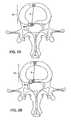
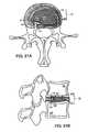
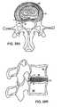
- FIG. 1Ashows an axial view of a portion of a functional spine unit, in which part of a vertebra and intervertebral disc are depicted;
- FIG. 1Bshows an sagittal cross section of a portion of a functional spine unit shown in FIG. 1A, in which two lumbar vertebrae and the intervertebral disc are visible;
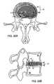
- FIG. 2Ashows an axial view of one aspect of the invention showing a portion of the FSU prior to supporting a herniated segment
- FIG. 2Bshows an axial view of the construct in FIG. 2A supporting the herniated segment
- FIG. 3Ashows an axial view of another embodiment of the disclosed invention after placement of the device
- FIG. 3Bshows an axial view of the construct in FIG. 3 a after tension is applied to support the herniated segment
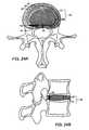
- FIG. 4Ashows an axial view of an alternate embodiment of the invention
- FIG. 4Bshows a sagittal view of the alternate embodiment shown in FIG., 4 A;
- FIG. 5Ashows an axial view of another aspect of the present invention.
- FIG. 5Bshows the delivery tube of FIG. 5A being used to displace the herniated segment to within its pre-herniated borders;
- FIG. 5Cshows a one-piece embodiment of the invention in an anchored and supporting position
- FIG. 6shows one embodiment of the invention supporting a weakened posterior annulus fibrosis
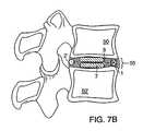
- FIG. 7Ashows an axial view of another aspect of the disclosed invention demonstrating two stages involved in augmentation of the soft tissues of the disc;
- FIG. 7Bshows a sagittal view of the invention shown in FIG., 7 A;
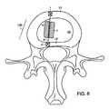
- FIG. 8shows an axial view of one aspect of the disclosed invention involving augmentation of the soft tissues of the disc and support/closure of the annulus fibrosis;
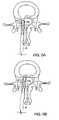
- FIG. 9Ashows an axial view of one aspect of the invention involving augmentation of the soft tissues of the disc with the flexible augmentation material anchored to the anterior lateral annulus fibrosis;
- FIG. 9Bshows an axial view of one aspect of the disclosed invention involving augmentation of the soft tissues of the disc with the flexible augmentation material anchored to the annulus fibrosis by a one piece anchor;
- FIG. 10Ashows an axial view of one aspect of the disclosed invention involving augmentation of the soft tissues of the disc.
- FIG. 10Bshows the construct of FIG. 10A after the augmentation material has been inserted into the disc.
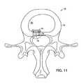
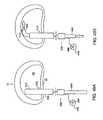
- FIG. 11illustrates an axial view of a barrier mounted within an annulus.
- FIG. 12shows a sagittal view of the barrier of FIG. 11 .
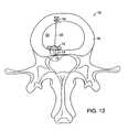
- FIG. 13shows an axial view of a barrier anchored within a disk.
- FIG. 14illustrates a sagittal view of the barrier shown in FIG. 13 .
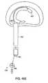
- FIG. 15illustrates the use of a second anchoring device for a barrier mounted within a disk.
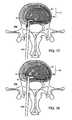
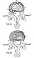
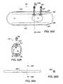
- FIG. 16Ais an axial (transverse) view of the intervertebral disk.
- FIG. 16Bis a sagittal section along the midline of the intervertebral disk.
- FIG. 17is an axial view of the intervertebral disc with the right half of a sealing means of a barrier means being placed against the interior aspect of a defect in annulus fibrosis by a dissection/delivery tool.
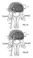
- FIG. 18illustrates a full sealing means placed on the interior aspect of a defect in annulus fibrosis.
- FIG. 19depicts the sealing means of FIG. 18 being secured to tissues surrounding the defect.
- FIG. 20depicts the sealing means of FIG. 19 after fixation means have been passed into surrounding tissues.
- FIG. 21Adepicts an axial view of the sealing means of FIG. 20 having enlarging means inserted into the interior cavity.
- FIG. 21Bdepicts the construct of FIG. 21 in a sagittal section.
- FIG. 22Ashows an alternative fixation scheme for the sealing means and enlarging means.
- FIG. 22Bshows the construct of FIG. 22A in a sagittal section with an anchor securing a fixation region of the enlarging means to a superior vertebral body in a location proximate to the defect.
- FIG. 23Adepicts an embodiment of the barrier means of the present invention being secured to annulus 10 using fixation means.
- FIG. 23Bdepicts an embodiment of the barrier means of FIG. 23A secured to annulus by two fixation darts wherein the fixation tool has been removed.
- FIGS. 24A and 24Bdepict a barrier means positioned between layers of the annulus fibrosis on either side of a defect.
- FIG. 25depicts an axial cross section of a large version of a barrier means.
- FIG. 26depicts an axial cross section of a barrier means in position across a defect following insertion of two augmentation devices.
- FIG. 27depicts the barrier means as part of elongated augmentation device.
- FIG. 28Adepicts an axial section of an alternate configuration of the augmentation device of FIG. 27 .
- FIG. 28Bdepicts a sagittal section of an alternate configuration of an augmentation device of FIG. 27 .
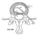
- FIGS. 29A-Ddepict deployment of a barrier from entry site remote from the defect in annulus fibrosis.
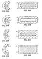
- FIGS. 30A and 30B, 31 A and 31 B, 32 A and 32 B and 33 A and 33 Bdepict axial and sectional views, respectively of embodiments of the barrier.
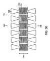
- FIG. 34shows a non-axisymmetric expansion means
- FIGS. 35 and 36illustrate alternate embodiments of the expansion means shown in FIG. 34 .
- FIGS. 37A, 37 B and 37 Cillustrate a side, front, and perspective view respectively, of an alternate embodiment of expansion means shown in FIG. 34 .
- FIG. 38shows an alternate expansion means to that shown in FIG. 37 A.
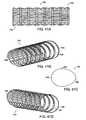
- FIGS. 39A-39Dillustrate a tubular expansion means having a circular cross-section.
- FIGS. 40A-40Dillustrate a tubular expansion means having an oval shaped cross-section.
- FIGS. 40E, 40 F and 40 Iillustrate a front, back and top view, respectively of the tubular expansion means of FIG. 40A having a sealing means covering an exterior surface of an annulus face.
- FIGS. 40G and 40Hshow the tubular expansion means of FIG. 40A having a sealing means covering an interior surface of an annulus face.
- FIGS. 41A-41Dillustrate a tubular expansion means having an egg-shaped cross-section.
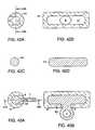
- FIGS. 42A-Ddepict cross sections of a preferred embodiment of sealing means and enlarging means.
- FIGS. 43A and 43Bdepict an alternative configuration of enlarging means.
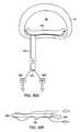
- FIGS. 44A and 44Bdepict an alternative shape of the barrier means.
- FIG. 45is a section of a device used to affix sealing means to tissues surrounding a defect.
- FIG. 46depicts the use of thermal device to heat and adhere sealing means to issues surrounding a defect.
- FIG. 47depicts an expandable thermal element that can be used to adhere sealing means to tissues surrounding a defect.
- FIG. 48depicts an alternative embodiment to the thermal device.
- FIGS. 49A through 49Gillustrate a method of implanting an intradiscal implant.
- FIGS. 50A through 50Fshow an alternate method of implanting an intradiscal implant.
- FIGS. 51A through 51Cshow another alternate method of implanting an intradiscal implant.
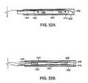
- FIGS. 52A and 52Billustrate an implant guide used with the intradiscal implant system.
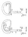
- FIG. 53Aillustrates a barrier having stiffening plate elements.
- FIG. 53Billustrates a sectional view of the barrier of FIG. 53 A.
- FIG. 54Ashows a stiffening plate
- FIG. 54Bshows a sectional view of the stiffening plate of FIG. 54 A.
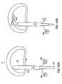
- FIG. 55Aillustrates a barrier having stiffening rod elements.
- FIG. 55Billustrates a sectional view of the barrier of FIG. 55 A.
- FIG. 56Aillustrates a stiffening rod
- FIG. 56Billustrates a sectional view of the stiffening rod of FIG. 56 A.
- FIG. 57shows an alternate configuration for the location of the fixation devices of the barrier of FIG. 44 A.
- a functional spine unitincludes the bony structures of two adjacent vertebrae (or vertebral bodies), the soft tissue (annulus fibrosis (AF), and optionally nucleus pulposus (NP)) of the intervertebral disc, and the ligaments, musculature and connective tissue connected to the vertebrae.
- the intervertebral discis substantially situated in the intervertebral space formed between the adjacent vertebrae.
- Augmentation of the functional spine unitcan include repair of a herniated disc segment, support of a weakened, torn or damaged annulus fibrosis, or the addition of material to or replacement of all or part of the nucleus pulposus.
- Augmentation of the functional spine unitis provided by herniation constraining devices and disc augmentation devices situated in the intervertebral disc space.
- FIGS. 1A and 1Bshow the general anatomy of a functional spine unit 45 .
- the terms ‘anterior’ and ‘posterior’, ‘superior’ and ‘inferior’are defined by their standard usage in anatomy, i.e., anterior is a direction toward the front (ventral) side of the body or organ, posterior is a direction toward the back (dorsal) side of the body or organ; superior is upward toward the head and inferior is lower or toward the feet.
- FIG. 1Ais an axial view (transverse) along transverse axis M of a vertebral body with the intervertebral disc 15 superior to the vertebral body.
- Axis Mshows the anterior (A) and posterior (P) orientation of the functional spine unit within the anatomy.
- the intervertebral disc 15contains the annulus fibrosis (AF) 10 which surrounds a central nucleus pulposus (NP) 20 .
- Herniated segment 30is depicted by a dashed-line. Herniated segment 30 protrudes beyond the pre-herniated posterior border 40 of the disc. Also shown in this figure are the left 70 and right 70 ′ transverse spinus processes and the posterior spinus process 80 .
- FIG. 1Bis a sagittal section along sagittal axis N through the midline of two adjacent vertebral bodies 50 (superior) and 50 ′ (inferior).
- Intervertebral disc space 55is formed between the two vertebral bodies and contains intervertebral disc 15 , which supports and cushions the vertebral bodies and permits movement of the two vertebral bodies with respect to each other and other adjacent functional spine units.
- Intervertebral disc 15is comprised of the outer AF 10 which normally surrounds and constrains the NP 20 to be wholly within the borders of the intervertebral disc space.
- herniated segment 30represented by the dashed-line, has migrated posterior to the pre-herniated border 40 of the posterior AF of the disc.
- Axis Mextends between the anterior (A) and posterior (P) of the functional spine unit.
- the vertebral bodiesalso include facet joints 60 and the superior 90 and inferior 90 ′ pedicle that form the neural foramen 100 .
- Disc height lossoccurs when the superior vertebral body 50 moves inferiorly relative to the inferior vertebral body 50 ′.
- the disc herniation constraining devices 13provide support for returning all or part of the herniated segment 30 to a position substantially within its pre-herniated borders 40 .
- the disc herniation constraining deviceincludes an anchor which is positioned at a site within the functional spine unit, such as the superior or inferior vertebral body, or the anterior, medial, or anterior lateral annulus fibrosis.
- the anchoris used as a point against which all or part of the herniated segment is tensioned so as to return the herniated segment to its pre-herniated borders, and thereby relieve pressure on otherwise compressed neural tissue and structures.
- a support memberis positioned in or posterior to the herniated segment, and is connected to the anchor by a connecting member.
- augmentation materialis secured within the intervertebral disc space, which provides assists the NP in cushioning and supporting the inferior and superior vertebral bodies.
- a supporting member, located opposite the anchor,may optionally provide a second point of attachment for the connecting member and further hinder the movement of the augmentation material within the intervertebral disk space.
- FIGS. 2A and 2Bdepict one embodiment of device 13 .
- FIG. 2Ashows the elements of the constraining device in position to correct the herniated segment.
- Anchor 1is securely established in a location within the functional spine unit, such as the anterior AF shown in the figure.
- Support member 2is positioned in or posterior to herniated segment 30 .
- connection member 3Leading from and connected to anchor 1 is connection member 3 , which serves to connect anchor 1 to support member 2 .
- the connection membermay traverse through all or part of the herniated segment.
- FIG. 2Bshows the positions of the various elements of the herniation constraining device 13 when the device 13 is supporting the herniating segment.
- Tightening connection member 2allows it to transmit tensile forces along its length, which causes herniated segment 30 to move anteriorly, i.e., in the direction of its pre-herniated borders.
- connection member 3is secured in a permanent fashion between anchor 1 and support member 2 . This maintains tension between anchor 1 and support member 2 and restricts motion of the herniated segment to within the pre-herniated borders 40 of the disc.
- Support member 2is used to anchor to herniated segment 30 , support a weakened AF in which no visual evidence of herniation is apparent, and it may also be used to close a defect in the AF of herniated segment 30 .
- Anchor 1is depicted in a representative form because it can take one of many forms, be made from one of a variety of biocompatible materials, and be constructed so as to have one of a range of stiffness. It can be a permanent device constructed of durable plastic or metal or can be made from a resorbable material such as polylactic acid (PLA) or polyglycolic acid (PGA). Specific embodiments are not shown, but many possible designs would be obvious to anyone skilled in the art. Embodiments include, but are not limited to, a barbed anchor made of PLA or a metal coil that can be screwed into the anterior AF.
- PLApolylactic acid
- PGApolyglycolic acid
- Anchor 1can be securely established within a portion of the functional spine unit in the usual and customary manner for such devices and locations, such as being screwed into bone, sutured into tissue or bone, or affixed to tissue or bone using an adhesive method, such as cement, and suitable surgical adhesives. Once established within the bone or tissue, anchor 1 should remain relatively stationary within the bone or tissue.
- Support member 2is also depicted in a representative format and shares the same flexibility in material and design as anchor 1 . Both device elements can be of the same design, or they can be of different designs, each better suited to being established in healthy and diseased tissue respectively. Alternatively, in other forms, support member 2 can be a cap or a bead shape, which also serves to secure a tear or puncture in the AF, or it can be bar or plate shaped, with or without barbs to maintain secure contact with the herniated segment. Support member 2 can be established securely to, within, or posterior to the herniated segment.
- the anchor and support membercan include suture, bone anchors, soft tissue anchors, tissue adhesives, and materials that support tissue ingrowth although other forms and materials are possible. They may be permanent devices or resorbable. Their attachment to a portion of FSU and herniated segment must be strong enough to resist the tensional forces that result from repair of the hernia and the loads generated during daily activities.
- Connection member 3is also depicted in representative fashion.
- Member 3may be in the format of a flexible filament, such as a single or multi-strand suture, wire, or maybe a rigid rod or broad band of material, for example.
- the connection membercan further include suture, wire, pins, and woven tubes or webs of material. It can be constructed from a variety of materials, either permanent or resorbable, and can be of any shape suitable to fit within the confines of the intervertebral disc space.
- the material chosenis preferably adapted to be relatively stiff while in tension, and relatively flexible against all other loads. This allows for maximal mobility of the herniated segment relative to the anchor without the risk of the supported segment moving outside of the pre-herniated borders of the disc.
- connection membermay be an integral component of either the anchor or support member or a separate component.
- connection member and support membercould be a length of non-resorbing suture that is coupled to an anchor, and tensioned against the anchor, and sewn to the herniated segment.
- FIGS. 3A and 3Bdepict another embodiment of device 13 .
- Anchor 1is positioned in the AF, and connection member 3 is attached to anchor 1 .
- Support member 4is positioned posterior to the posterior-most aspect of herniated segment 30 . In this way, support member 4 does not need to be secured in herniated segment 30 to cause herniated segment 30 to move within the pre-herniated borders 40 of the disc.
- Support member 4has the same flexibility in design and material as anchor 1 , and may further take the form of a flexible patch or rigid plate or bar of material that is either affixed to the posterior aspect of herniated segment 30 or is simply in a form that is larger than any hole in the AF directly anterior to support member 4 .
- FIG. 3Bshows the positions of the elements of the device when tension is applied between anchor 1 and support member 4 along connection member 3 .
- the herniated segmentis displaced anteriorly, within the pre-herniated borders 40 of the disc.
- FIGS. 4A and 4Bshow five examples of suitable anchoring sites within the FSU for anchor 1 .
- FIG. 4Ashows an axial view of anchor 1 in various positions within the anterior and lateral AF.
- FIG. 4Bsimilarly shows a sagittal view of the various acceptable anchoring sites for anchor 1 .
- Anchor 1is secured in the superior vertebral body 50 , inferior vertebral body 50 ′ or anterior AF 10 , although any site that can withstand the tension between anchor 1 and support member 2 along connection member 3 to support a herniated segment within its pre-herniated borders 40 is acceptable.
- a suitable position for affixing one or more anchorsis a location anterior to the herniated segment such that, when tension is applied along connection member 3 , herniated segment 30 is returned to a site within the pre-herniated borders 40 .
- the site chosen for the anchorshould be able to withstand the tensile forces applied to the anchor when the connection member is brought under tension. Because most symptomatic herniations occur in the posterior or posterior lateral directions, the preferable site for anchor placement is anterior to the site of the herniation. Any portion of the involved FSU is generally acceptable, however the anterior, anterior medial, or anterior lateral AF is preferable.
- anchor 1can be a single anchor in any of the shown locations, or there can be multiple anchors 1 affixed in various locations and connected to a support member 2 to support the herniated segment.
- Connection member 3can be one continuous length that is threaded through all the sited anchors and the support member, or it can be several individually strands of material each terminated under tension between an anchor and one or more support members.
- the anchor(s) and connection membermay be introduced and installed in the patient, with the connection member under tension.
- those elementsmay be installed, without introducing tension to the connection member, but where the connection member is adapted to be under tension when the patient is in a non-horizontal position, i.e., resulting from loading in the IV disc.
- FIGS. 5A, B, and Cshow an alternate embodiment of herniation constraining device 13 a .
- device 13 aa substantially one-piece construct, is delivered through a delivery tube 6 , although device 13 a could be delivered in a variety of ways including, but not limited to, by hand or by a hand held grasping instrument.
- device 13 a in delivery tube 6is positioned against herniated segment 30 .
- the herniated segmentis displaced within its pre-herniated borders 40 by device 13 a and/or delivery tube 6 such that when, in FIG.
- device 13 ahas been delivered through delivery tube 6 , and secured within a portion of the FSU, the device supports the displaced herniated segment within its pre-herniated border 40 .
- Herniation constraining device 13 acan be made of a variety of materials and have one of many possible forms so long as it allows support of the herniated segment 30 within the pre-herniated borders 40 of the disc.
- Device 13 acan anchor the herniated segment 30 to any suitable anchoring site within the FSU, including, but not limited to the superior vertebral body, inferior vertebral body, or anterior AF.
- Device 13 amay be used additionally to close a defect in the AF of herniated segment 30 . Alternatively, any such defect may be left open or may be closed using another means.
- FIG. 6depicts the substantially one-piece device 13 a supporting a weakened segment 30 ′ of the posterior AF 10 ′.
- Device 13 ais positioned in or posterior to the weakened segment 30 ′ and secured to a portion of the FSU, such as the superior vertebral body 50 , shown in the figure, or the inferior vertebral body 50 ′ or anterior, medial, anterior lateral annulus fibrosis 10 .
- a portion of the FSUsuch as the superior vertebral body 50 , shown in the figure, or the inferior vertebral body 50 ′ or anterior, medial, anterior lateral annulus fibrosis 10 .
- a weakened or torn AFthat may not to be protruding beyond the pre-herniated borders of the disc may still induce the surgeon to remove all or part of the NP in order to decrease the risk of herniation.
- any of the embodiments of the inventionmay be used to support and perhaps close defects in or weakened segments of AF.
- FIGS. 7A and 7Bshow one embodiment of device 13 securing augmentation material in the intervertebral disc space 55 .
- anchors 1have been established in the anterior AF 10 .
- Augmentation material 7is in the process of being inserted into the disc space along connection member 3 which, in this embodiment, has passageway 9 .
- Support member 2 ′is shown ready to be attached to connection member 3 once the augmentation material 7 is properly situated.
- connection member 3passes through an aperture 11 in support member 2 ′, although many other methods of affixing support member 2 ′ to connection member 3 are possible and within the scope of this invention.
- Augmentation material 7may have a passageway 9 , such as a channel, slit or the like, which allows it to slide along the connection member 3 , or augmentation material 7 may be solid, and connection member 3 can be threaded through augmentation material by means such as needle or other puncturing type device.
- Connection member 3is affixed at one end to anchor 1 and terminated at its other end by a support member 2 ′, one embodiment of which is shown in the figure in a cap-like configuration.
- Support member 2 ′can be affixed to connection member 3 in a variety of ways, including but not limited, to swaging support member 2 ′ to connection member 3 .
- support member 2 ′is in a cap configuration and has a dimension (diameter or length and width) larger than the optional passageway 9 , which serves to prevent augmentation material 7 from displacing posteriorly with respect to anchor 1 .
- the right half of the intervertebral disc of FIG. 7A (in axial view) and FIG. 7B (in sagittal view)show augmentation material 7 that has been implanted into the disc space 55 along connection member 3 where it supports the vertebral bodies 50 and 50 ′.
- FIG. 7Ashows an embodiment in which support member 2 ′ is affixed to connection member 3 and serves only to prevent augmentation material 7 from moving off connection member 3 .
- the augmentation deviceis free to move within the disc space.
- FIG. 7Bshows an alternate embodiment in which support member 2 ′ is embedded in a site in the functional spine unit, such as a herniated segment or posterior annulus fibrosis, to further restrict the movement of augmentation material 7 within the disc space.
- Augmentation materialcan be made of any biocompatible, preferably flexible, material.
- a flexible materialis preferably fibrous, like cellulose or bovine or autologous collagen.
- the augmentation materialcan be shaped like plugs, discs, cubelike, ellipsoid, spheroid or any other suitable shape.
- the augmentation materialcan be secured within the intervertebral space by a variety of methods, such as but not limited to, a suture loop attached to, around, or through the material, which is then passed to the anchor and support member.
- FIGS. 8, 9 A, 9 B and 10 A and 10 Bdepict further embodiments of the disc herniation constraining device 13 b in use for augmenting soft tissue, particularly tissue within the intervertebral space.
- device 13 Bis secured within the intervertebral disc space providing additional support for NP 20 .
- Anchor 1is securely affixed in a portion of the FSU, (anterior AF 10 in these figures).
- Connection member 3terminates at support member 2 , preventing augmentation material 7 from migrating generally posteriorly with respect to anchor 1 .
- Support member 2is depicted in these figures as established in various locations, such as the posterior AF 10 ′ in FIG.
- support member 2may be anchored in any suitable location within the FSU, as described previously.
- Support member 2may be used to close a defect in the posterior AF. It may also be used to displace a herniated segment to within the pre-herniated borders of the disc by applying tension between anchoring means 1 and 2 along connection member 3 .
- FIG. 9Adepicts anchor 1 , connection member 3 , augmentation material 7 and support member 2 ′ (shown in the “cap”-type configuration) inserted as a single construct and anchored to a site within the disc space, such the inferior or superior vertebral bodies.
- This configurationsimplifies insertion of the embodiments depicted in FIGS. 7 and 8 by reducing the number of steps to achieve implantation.
- Connection member 3is preferably relatively stiff in tension, but flexible against all other loads.
- Support member 2 ′is depicted as a bar element that is larger than passageway 9 in at least one plane.
- FIG. 9Bdepicts a variation on the embodiment depicted in FIG. 9 A.
- FIG. 9Bshows substantially one-piece disc augmentation device 13 C, secured in the intervertebral disc space.
- Device 13 Chas anchor 1 , connection member 3 and augmentation material 7 .
- Augmentation material 7 and anchor 1could be pre-assembled prior to insertion into the disc space 55 as a single construct.
- augmentation material 7could be inserted first into the disc space and then anchored to a portion of the FSU by anchor 1 .
- FIGS. 10A and 10Bshow yet another embodiment of the disclosed invention, 13 D.
- two connection members 3 and 3 ′are attached to anchor 1 .
- Two plugs of augmentation material 7 and 7 ′are inserted into the disc space along connection members 3 and 3 ′.
- Connection members 3 and 3 ′are then bound together (i.e., knotted together, fused or the like). This forms loop 3 ′′ that serves to prevent augmentation materials 7 and 7 ′ from displacing posteriorly.
- FIG. 10Bshows the position of the augmentation material 7 after it is secured by the loop 3 ′′ and anchor 1 .
- augmentation materialsuch as using a single plug of augmentation material, or two connection members leading from anchor 1 with each of the connection members being bound to at least one other connection member. It could further be accomplished with more than one anchor with at least one connection member leading from each anchor, and each of the connection members is be bound to at least one other connection member.
- any of the devices described hereincan be used for closing defects in the AF whether created surgically or during the herniation event. Such methods may also involve the addition of biocompatible material to either the AF or NP. This material could include sequestered or extruded segments of the NP found outside the pre-herniated borders of the disc.
- FIGS. 11-15illustrate devices used in and methods for closing a defect in an annulus fibrosis.
- One methodinvolves the insertion of a barrier or barrier means 12 into the disc 15 . This procedure can accompany surgical discectomy. It can also be done without the removal of any portion of the disc 15 and further in combination with the insertion of an augmentation material or device into the disc 15 .
- the methodconsists of inserting the barrier means 12 into the interior of the disc 15 and positioning it proximate to the interior aspect of the annular defect 16 .
- the barrier materialis preferably considerably larger in area than the size of the defect 16 , such that at least some portion of the barrier means 12 abuts healthier annulus fibrosis 10 .
- the deviceacts to seal the annular defect 16 , recreating the closed isobaric environment of a healthy disc nucleus 20 . This closure can be achieved simply by an over-sizing of the implant relative to the defect 16 . It can also be achieved by affixing the barrier means 12 to tissues within the functional spinal unit.
- the barrier 12is affixed to the annulus surrounding the annular defect 16 .
- the barrier means 12can also be larger in area than the defect 16 and be affixed to a tissue or structure opposite the defect 16 , i.e. anterior tissue in the case of a posterior defect.
- the barrier means 12is preferably flexible in nature. It can be constructed of a woven material such as Dacron or Nylon and can further be an expanded material, such as expanded polytetrafluroethelene (e-PTFE), for example.
- the barrier means 12can also be a biologic material such as cross-linked collagen or cellulous.
- the barrier means 12can be a single piece of material. It can have an expandable means or component that allows it to be expanded from a compressed state after insertion into the interior of the disc 15 .
- This expandable meanscan be active, such as a balloon, or passive, such as a hydrophilic material.
- the expandable meanscan also be a self expanding mesh of elastically deforming material, for example.
- FIGS. 11 and 12illustrate a barrier 12 mounted within an annulus 10 and covering an annular defect 16 .
- the barrier 12can be secured to the annulus 10 with a fixation mechanism or fixation means 14 .
- the fixation means 14can include a plurality of suture loops placed through the barrier 12 and the annulus 10 . Such fixation can prevent motion or slipping of the barrier 12 away from the annular defect 16 .
- the barrier means 12can also be anchored to the disc 15 in multiple locations.
- the barrier means 12can be affixed to the annular tissue 10 in or surrounding the defect and further affixed to a secondary fixation site opposite the defect, i.e. the anterior annulus 10 in a posterior herniation or the inferior 50 ′ or superior 50 vertebral body.
- fixation means 14can be used to attach the barrier 12 to the annulus 10 near the defect 16
- an anchoring mechanism 18can secure the barrier 12 to a secondary fixation site.
- a connector 22can attach the barrier 12 to the anchor 18 .
- Tensioncan be applied between the primary and secondary fixation sites through a connector 22 so as to move the annular defect 16 toward the secondary fixation site. This may be particularly beneficial in closing defects 16 that result in posterior herniations. By using this technique, the herniation can be moved and supported away from any posterior neural structures while further closing any defect in the annulus 10 .
- the barrier means 12can further be integral to a fixation means such that the barrier means affixes itself to tissues within the functional spinal unit.
- any of the methods described abovecan be augmented by the use of a second barrier or a second barrier means 24 placed proximate to the outer aspect of the defect 16 as shown in FIG. 15 .
- the second barrier 24can further be affixed to the inner barrier means 12 by the use of a fixation means 14 such as suture material.
- FIGS. 16A and 16Bdepicts intervertebral disc 15 comprising nucleus pulposus 20 and annulus fibrosis 10 .
- Nucleus pulposus 20forms a first anatomic region and extra-discal space 500 (any space exterior to the disc) forms a second anatomic region wherein these regions are separated by annulus 10 .
- FIG. 16Ais an axial (transverse) view of the intervertebral disc.
- a posterior lateral defect 16 in annulus fibrosis 10has allowed a segment 30 of nucleus pulposus 20 to herniate into an extra discal space 500 .
- Interior aspect 32 and exterior aspect 34are shown, as are the right 70 ′ and left 70 transverse processes and posterior process 80 .
- FIG. 16Bis a sagittal section along the midline intervertebral disc.
- Superior pedicle 90 and inferior pedicle 90 ′extend posteriorly from superior vertebral body 95 and inferior vertebral body 95 ′ respectively.
- a barrier or barrier means 12can be placed into a space between the annulus 10 and the nucleus 20 proximate to the inner aspect 32 of defect 16 , as depicted in FIGS. 17 and 18.
- the spacecan be created by blunt dissection. Dissection can be achieved with a separate dissection instrument, with the barrier means 12 itself, or a combined dissection/barrier delivery tool 100 .
- This spaceis preferably no larger than the barrier means such that the barrier means 12 can be in contact with both annulus 10 and nucleus 20 . This allows the barrier means 12 to transfer load from the nucleus 20 to the annulus 10 when the disc is pressurized during activity.
- the barrier means 12preferably spans the defect 16 and extends along the interior aspect 36 of the annulus 10 until it contacts healthy tissues on all sides of the defect 16 .
- the contacted tissuescan include the annulus 10 , cartilage overlying the vertebral endplates, and/or the endplates themselves.
- the barrier means 12consists of two components a sealing means or sealing component 51 and an enlarging means or enlarging component 53 , shown in FIGS. 21A and 21B.
- the sealing means 51forms the periphery of the barrier 12 and has an interior cavity 17 . There is at least one opening 8 leading into cavity 17 from the exterior of the sealing means 51 .
- Sealing means 51is preferably compressible or collapsible to a dimension that can readily be inserted into the disc 15 through a relatively small hole. This hole can be the defect 16 itself or a site remote from the defect 16 .
- the sealing means 51is constructed from a material and is formed in such a manner as to resist the passage of fluids and other materials around sealing means 51 and through the defect 16 .
- the sealing means 51can be constructed from one or any number of a variety of materials including, but not limited to PTFE, e-PTFE, Nylon TM, Marlex TM, and/or collagen.
- the enlarging means 53can be sized to fit within cavity 17 of sealing means 51 . It is preferably a single object of a dimension that can be inserted through the same defect 16 through which the sealing means 51 was passed.
- the enlarging means 53can expand the sealing means 51 to an expanded state as it is passed into cavity 17 .
- One purpose of enlarging means 53is to expand sealing means 51 to a size greater than that of the defect 16 such that the assembled barrier 12 prevents passage of material through the defect 16 .
- the enlarging component 53can further impart stiffness to the barrier means 12 such that the barrier means 12 will resist the pressures within nucleus pulposus 20 and expulsion through the defect 16 .
- the enlarging means 53can be constructed from one or any number of materials including, but not limited to silicon rubber, various plastics, stainless steel, NITINOL or other metals. These materials may form a solid object, a hollow object, coiled springs or other suitable forms capable of filling cavity 17 within sealing means 51 .
- the sealing means 51 , enlarging means 53 , or the barrier means 12 constructcan further be affixed to tissues either surrounding the defect 16 or remote from the defect 16 .
- no aspect of a fixation means or fixation device or the barrier means 12 and its componentsextends posterior to the disc 15 and into the second anatomic region 500 . This avoids the risk of contacting and irritating the sensitive nerve tissues posterior to the disc 15 .
- the sealing means 51is inserted into the disc 15 proximate the interior aspect 36 of the defect.
- the sealing means 51is then affixed to the tissues surrounding the defect using a suitable fixation means, such as suture or a soft-tissue anchor.
- the fixation procedureis preferably performed from the interior of the sealing means cavity 17 as depicted in FIGS. 19 and 20.
- a fixation delivery instrument 110is delivered into cavity 17 through opening 8 in the sealing means 51 .
- Fixation devices 14can then be deployed through a wall of the sealing means 53 into surrounding tissues. Once the fixation means 14 have been passed into surrounding tissue, the fixation delivery instrument 110 can be removed from the disk 15 . This method eliminates the need for a separate entryway into the disc 15 for delivery of fixation means 14 .
- One or more fixation means 14can be delivered into one or any number of surrounding tissues including the superior 95 and inferior 95 ′ vertebral body.
- the enlarging means 53can be inserted into cavity 17 of the sealing means 51 to further expand the barrier means 12 construct as well as increase its stiffness, as depicted in FIGS. 21A and 21B.
- the opening 8 into the sealing means 51can then be closed by a suture or other means, although this is not a requirement of the present invention. In certain cases, insertion of a separate enlarging means may not be necessary if adequate fixation of the sealing means 51 is achieved.
- the enlarging means 53can have an integral fixation region 4 that facilitates securing it to tissues as depicted in FIGS. 22A, 22 B 32 A and 43 B.
- This fixation region 4can extend exterior to sealing means 51 either through opening 8 or through a separate opening.
- Fixation region 4can have a hole through which a fixation means or fixation device 14 can be passed.
- the barrier 12is affixed to at least one of the surrounding vertebral bodies ( 95 , 95 ′) proximate the defect using a bone anchor 14 ′.
- the bone anchor 14 ′can be deployed into the vertebral bodies 50 , 50 ′ at some angle between 0° and 180° relative to a bone anchor deployment tool. As shown the bone anchor 14 ′ is mounted at 90° relative to the bone anchor deployment tool.
- the enlarging means 53itself can have an integral fixation device 14 located at a site or sites along its length.
- fixation means 14can be darts 15 and are first passed partially into annulus 10 within a fixation device 120 , such as a hollow needle.
- fixation means 25can be advanced into the barrier means 12 and fixation device 120 removed.
- Fixation means 25preferably have two ends, each with a means to prevent movement of that end of the fixation device. Using this method, the fixation means can be lodged in both the barrier 12 and annulus fibrosis 10 without any aspect of fixation means 25 exterior to the disc in the second anatomic region 500 .
- the patch or barrier 12can be placed between two neighboring layers of the annulus 10 on either side of the defect 16 as depicted in FIGS. 24A and 24B.
- FIG. 24Ashows an axial view while 24 B shows a sagittal cross section. Such positioning spans the defect 16 .
- the barrier means 12can be secured using the methods outlined.
- barrier 12 for spinal applicationsis a patch having a length, oriented along the circumference of the disk, which is substantially greater than its height, which is oriented along the distance separating the surrounding vertebral bodies.
- a barrier 12 having a length greater than its heightis illustrated in FIG. 25 .
- the barrier 12can be positioned across the defect 16 as well as the entirety of the posterior aspect of the annulus fibrosis 10 .
- Such dimensions of the barrier 12can help to prevent the barrier 12 from slipping after insertion and can aid in distributing the pressure of the nucleus 20 evenly along the posterior aspect of the annulus 10 .
- the barrier 12can be used in conjunction with an augmentation device 11 inserted within the annulus 10 .
- the augmentation device 11can include separate augmentation devices 42 as shown in FIG. 26 .
- the augmentation device 11can also be a single augmentation device 44 and can form part of the barrier 12 as barrier region 300 , coiled within the annulus fibrosis 10 , as shown in FIG. 27 .
- Either the barrier 12 or barrier region 300can be secured to the tissues surrounding the defect 16 by fixation devices or darts 25 .
- the barrier or patch 12may be used as part of a method to augment the intervertebral disc.
- augmentation material or devicesare inserted into the disc through a defect (either naturally occurring or surgically generated). Many suitable augmentation materials and devices are discussed above and in the prior art.
- the barrier meansis then inserted to aid in closing the defect and/or to aid in transferring load from the augmentation materials/devices to healthy tissues surrounding the defect.
- the barrier meansis an integral component to an augmentation device.
- the augmentation portionmay comprise a length of elastic material that can be inserted linearly through a defect in the annulus.
- a region 300 of the lengthforms the barrier means of the present invention and can be positioned proximate to the interior aspect of the defect once the nuclear space is adequately filled. Barrier region 300 may then be affixed to surrounding tissues such as the AF and/or the neighboring vertebral bodies using any of the methods and devices described above.
- FIGS. 28A and 28Billustrate an axial section of an alternate configuration of an augmentation device 38 .
- barrier region 300extends across the defect 16 and has fixation region 4 facilitating fixation of the device 13 to superior vertebral body 50 with anchor 14 ′.
- FIGS. 29A-Dillustrate the deployment of a barrier 12 from an entry site 800 remote from the defect in the annulus fibrosis 10 .
- FIG. 29Ashows insertion instrument 130 with a distal end positioned within the disc space occupied by nucleus pulposus 20 .
- FIG. 29Bdepicts delivery catheter 140 exiting the distal end of insertion instrument 130 with barrier 12 on its distal end. Barrier 12 is positioned across the interior aspect of the defect 16 .
- FIG. 29Cdepicts the use of an expandable barrier 12 ′ wherein delivery catheter 140 is used to expand the barrier 12 ′ with balloon 150 (not seen) on its distal end. Balloon 150 may exploit heat to further adhere barrier 12 ′ to surrounding tissue.
- FIG. 29Ddepicts removal of balloon 150 and delivery catheter 140 from the disc space leaving expanded barrier means 12 ′ positioned across defect 16 .
- the barrier means 12includes a sealing means 51 comprised of a thermally adherent material that adheres to surrounding tissues upon the application of heat.
- the thermally adherent materialcan include thermoplastic, collagen, or a similar material.
- the sealing means 51can further comprise a separate structural material that adds strength to the thermally adherent material, such as a woven Nylon TM or Marlex TM.
- This thermally adherent sealing meanspreferably has an interior cavity 17 and at least one opening 8 leading from the exterior of the barrier means into cavity 17 .
- a thermal devicecan be attached to the insertion instrument shown in FIGS. 29C and 29D.
- the insertion instrument 130 having a thermal devicecan be inserted into cavity 17 and used to heat sealing means 51 and surrounding tissues.
- This devicecan be a simple thermal element, such as a resistive heating coil, rod or wire. It can further be a number of electrodes capable of heating the barrier means and surrounding tissue through the application of radio frequency (RF) energy.
- the thermal devicecan further be a balloon 150 , 150 ′, as shown in FIG. 47, capable of both heating and expanding the barrier means. Balloon 150 , 150 ′ can either be inflated with a heated fluid or have electrodes located about its surface to heat the barrier means with RF energy. Balloon 150 , 150 ′ is deflated and removed after heating the sealing means.
- An expander or enlarging means 53can also be an integral component of barrier 12 inserted within sealing means 51 . After the application of heat, a separate enlarging means 53 can be inserted into the interior cavity of the barrier means to either enlarge the barrier 12 or add stiffness to its structure. Such an enlarging means is preferably similar in make-up and design to those described above. Use of an enlarging means may not be necessary in some cases and is not a required component of this method.
- the barrier means 12 shown in FIG. 25preferably has a primary curvature or gentle curve along the length of the patch or barrier 12 that allows it to conform to the inner circumference of the AF 10 .
- This curvaturemay have a single radius R as shown in FIGS. 44A and 44B or may have multiple curvatures.
- the curvaturecan be fabricated into the barrier 12 and/or any of its components.
- the sealing meanscan be made without an inherent curvature while the enlarging means can have a primary curvature along its length. Once the enlarging means is placed within the sealing means the overall barrier means assembly takes on the primary curvature of the enlarging means. This modularity allows enlarging means with specific curvatures to be fabricated for defects occurring in various regions of the annulus.
- the cross sectional shape of the barrier means 12 meanscan be any of a number of shapes.
- Each embodimentexploits a sealing means 51 and an enlarging means 53 that may further add stiffness to the overall barrier construct.
- FIGS. 30A and 30Bshow an elongated cylindrical embodiment with enlarging means 53 located about the long axis of the device.
- FIGS. 31A and 31Bdepicts a barrier means comprising an enlarging means 53 with a central cavity 49 .
- FIGS. 32A and 32Bdepicts a barrier means comprising a non-axisymmetric sealing means 51 . In use, the longer section of sealing means 51 as seen on the left side of this figure would extend between opposing vertebra 50 and 50 ′.
- FIG. 33A and 33Bdepict a barrier means comprising a non-axisymmetric sealing means 51 and enlarging means 53 .
- the concave portion of the barrier meanspreferably faces nucleus pulposus 20 while the convex surface faces the defect 16 and the inner aspect of the annulus fibrosis 10 .
- This embodimentexploits pressure within the disc to compress sealing means 51 against neighboring vertebral bodies 50 and 50 ′ to aid in sealing.
- the ‘C’ shape as shown in FIG. 33Ais the preferred shape of the barrier wherein the convex portion of the patch rests against the interior aspect of the AF while the concave portion faces the NP.
- this ‘C’ shaped barrier meansare positioned against the vertebral endplates or overlying cartilage. As the pressure within the nucleus increases, these portions of the patch are pressurized against the endplates with an equivalent pressure, preventing the passage of materials around the barrier means. Dissecting a matching cavity prior to or during patch placement can facilitate use of such a ‘C’ shaped patch.
- FIGS. 34 through 41depict various enlarging or expansion device's 53 that can be employed to aid in expanding a sealing element 51 within the intervertebral disc 15 .
- Each embodimentcan be covered by, coated with, or cover the sealing element 51 .
- the sealing element 51 or membranecan be a sealer which can prevent flow of a material within the annulus fibrosus of the intervertebral disk through a defect in the disk.
- the material within the annuluscan include a nucleus pulposus or a prosthetic augmentation device, such as a hydrogel.
- the sealing means 51can further be woven through the expansion means 53 .
- FIGS. 34 through 38depict alternative patterns to that illustrated in FIG. 33 A.
- FIG. 33Ashows the expansion devices 53 within the sealing means 51 .
- the sealing meanscan alternatively be secured to one or another face (concave or convex) of the expansion means 53 . This can have advantages in reducing the overall volume of the barrier means 12 , simplifying insertion through a small diameter cannula. It can also allow the barrier means 12 to induce ingrowth of tissue on one face and not the other.
- the sealing means 51can be formed from a material that resists ingrowth such as expanded polytetraflouroethylene (e-PTFE).
- the expansion meanscan be constructed of a metal or polymer that encourages ingrowth.
- tissuecan grow into the expansion means 53 from outside of the disc 15 , helping to secure the barrier means 12 in place and seal against egress of materials from within the disc 15 .
- the expansion means 53 shown in FIG. 33Acan be inserted into the sealing means 51 once the sealing means 51 is within the disc 15 .
- the expansion means 53 and sealing means 51can be integral components of the barrier means 12 that an be inserted as a unit into the disc.
- the patterns shown in FIGS. 34 through 38can preferably be formed from a relatively thin sheet of material.
- the materialmay be a polymer, metal, or gel, however, the superelastic properties of nickel titanium alloy NITINOL makes this metal particularly advantageous in this application.
- Sheet thickness of between 0.03′′ to 0.10′′can provide adequate expansion force to maintain contact between the sealing means 51 and surrounding vertebral endplates.
- the patternmay be wire EDM'ed, cut by laser, or formed by other suitable means.
- FIG. 34shows an embodiment of a non-axisymmetric or expander 53 having a superior surface 166 and an inferior surface 168 .
- the expander 53can form a frame of a barrier 12 .
- This embodimentcomprises dissecting surfaces or ends 160 , radial elements or fingers 162 and a central strut 164 .
- the circular shape of the dissecting ends 160aid in dissecting through the nucleus pulposus 20 and/or along an inner surface of the annulus fibrosis 10 .
- the distance between the left-most and right-most points on the dissecting endsis the expansion means length 170 .
- This length 170preferably lies along the inner perimeter of the posterior annulus following implantation.
- the expander length 170can be as short as 3 mm and as long as the entire interior perimeter of the annulus fibrosis.
- the superior-inferior height of these dissecting ends 160is preferably similar to or larger than the posterior disc height.
- This embodimentemploys a multitude of fingers 162 to aid in holding a flexible sealer or membrane against the superior and inferior vertebral endplates.
- the distance between the superior-most point of the superior finger and the inferior-most point on the inferior fingeris the expansion means height 172 .
- This height 172is preferably greater than the disc height at the inner surface of the posterior annulus.
- the greater height 172 of the expander 153allows the fingers 162 to deflect along the superior and inferior vertebral endplates, enhancing the seal of the barrier means 12 against egress of material from within the disc 15 .
- the spacing between the fingers 162 along the expander length 170can be tailored to provide a desired stiffness of the expansion means 153 . Greater spacing between any two neighboring fingers 162 can further be employed to insure that the fingers 170 do not touch if the expansion means 153 is required to take a bend along its length.
- the central strut 164can connect the fingers and dissecting ends and preferably lies along the inner surface of the annulus 10 when seated within the disc 15 .
- Various embodimentsmay employ struts 164 of greater or lesser heights and thickness to vary the stiffness of the overall expansion means 153 along its length 170 and height 172 .
- FIG. 35depicts an alternative embodiment to the expander 153 of FIG. 34 .
- Openings or slots 174can be included along the central strut 164 . These slots 174 promote bending of the expander 153 and fingers 162 along a central line 176 connecting the centers of the dissecting ends 160 . Such central flexibility has been found to aid against superior or inferior migration of the barrier means or barrier 12 when the barrier 12 has not been secured to surrounding tissues.
- FIG. 36depicts an embodiment of the expander 153 of FIG. 33A with an enlarged central strut 164 and a plurality of slots 174 .
- This central strut 164can have a uniform stiffness against superior-inferior 166 , 168 bending as shown in this embodiment.
- the strut 164can alternatively have a varying stiffness along its height 178 to either promote or resist bending at a given location along the inner surface of the annulus 10 .
- FIGS. 37A, B, and Cdepict a further embodiment of the frame or expander 153 .
- This embodimentemploys a central lattice 180 consisting of multiple, fine interconnected struts 182 .
- Such a lattice 180can provide a structure that minimizes bulging of the sealing means 51 under intradiscal pressures.
- the orientation and location of these struts 182have been designed to give the barrier 12 a bend-axis along the middle of the expander height 172 .
- the struts 182support inferior 168 and superior 166 fingers 162 similar to previous embodiments. However, these fingers 162 can have varying dimensions and stiffness along the length of the barrier 12 .
- Such fingers 162cab be useful for helping the sealer 51 conform to uneven endplate geometries.
- FIG. 37 Billustrates the curved cross section 184 of the expander 153 of FIG. 37 A.
- This curve 184can be an arc segment of a circle as shown.
- the cross sectioncan be an ellipsoid segment or have a multitude of arc segments of different radii and centers.
- FIG. 37Cis a perspective view showing the three dimensional shape of the expander 153 of FIGS. 37A and 37B.
- FIG. 38depicts an expander 153 similar to that of FIG. 37A without fingers.
- the expander 153includes a central lattice 180 consisting of multiple struts 182 .
- FIGS. 39 through 41depict another embodiment of the expander 153 of the present invention.
- These tubular expanderscan be used in the barrier 12 embodiment depicted in FIG. 31 A.
- the sealer 51can cover the expander 153 as shown in FIG. 31 A.
- the sealer 51can cover the interior surface of the expander or an arc segment of the tube along its length on either the interior or exterior surface.
- FIG. 39depicts an embodiment of a tubular expander 154 .
- the superior 166 and interior surfaces 168 of the tubular expander 154can deploy against the superior and inferior vertebral endplates, respectively.
- the distance 186 between the superior 166 and inferior 168 surfaces of the expander 154are preferably equal to or greater than the posterior disc height at the inner surface of the annulus 10 .
- This embodimenthas an annulus face 188 and nucleus face 190 as shown in FIGS. 39B, 39 C and 39 D.
- the annulus face 188can be covered by the sealer 51 from the superior 166 to inferior 168 surface of the expander 154 .
- This face 188lies against the inner surface of the annulus 10 in its deployed position and can prevent egress of materials from within the disc 15 .
- the primary purpose of the nucleus face 190is to prevent migration of the expander 154 within the disc 15 .
- the struts 192 that form the nucleus face 190can project anteriorly into the nucleus 20 when the barrier 12 is positioned across the posterior wall of the annulus 10 . This anterior projection can resist rotation of the tubular expansion means 154 about its long axis. By interacting with the nucleus 20 , the struts 192 can further prevent migration around the circumference of the disc 15 .
- the struts 192can be spaced to provide nuclear gaps 194 . These gaps 194 can encourage the flow of nucleus pulposus 20 into the interior of the expander 154 . This flow can insure full expansion of the barrier 12 within the disc 15 during deployment.
- FIG. 39has a circular cross section 196 as seen in FIG. 39 C. If the superior-inferior height 186 of the expander 154 is greater than that of the disc 15 , this circular cross section 196 can deform into an oval when deployed, as the endplates of the vertebrae compress the expander 154 .
- the embodiment of the expander 154 shown in FIG. 40is preformed into an oval shape 198 shown in FIG. 40 C. Compression by the endplates can exaggerate the unstrained oval 198 .
- This oval 198can provide greater stability against rotation about a long axis of the expander 154 .
- FIGS. 39has a circular cross section 196 as seen in FIG. 39 C. If the superior-inferior height 186 of the expander 154 is greater than that of the disc 15 , this circular cross section 196 can deform into an oval when deployed, as the endplates of the vertebrae compress the expander 154 .
- the embodiment of the expander 154 shown in FIG. 40
- 41B, 41 C and 41 Ddepict an ‘egg-shaped’ cross section 202 , as shown in FIG. 41C, that can allow congruity between the curvature of the expander 154 and the inner wall of posterior annulus 10 .
- Any of a variety of alternate cross sectional shapescan be employed to obtain a desired fit or expansion force without deviating from the spirit of the present invention.
- FIGS. 40E, 40 F and 401depict the expander 154 of FIGS. 40A, 40 B, 40 C, and 40 D having a sealing means 51 covering the exterior surface of the annulus face 188 .
- This sealing means 51can be held against the endplates and the inner surface of the posterior annulus by the expander 154 in its deployed state.
- FIGS. 40G and 40Hdepict the expander 154 of FIG. 40B with a sealer 51 covering the interior surface of the annulus face 188 .
- This position of the sealer 51can allow the expander 154 to contact both the vertebral endplates and inner surface of the posterior annulus. This can promote ingrowth of tissue into the expander 154 from outside the disc 15 .
- Combinations of sealer 51 that cover all or part of the expander 154can also be employed without deviating from the scope of the present invention.
- the expander 154can also have a small pore size thereby allowing retention of a material such as a nucleus pulposus, for example, without the need for a sealer as a covering.
- FIGS. 42A-Ddepicts cross sections of a preferred embodiment of sealing means 51 and enlarging means 53 .
- Sealing device 51has internal cavity 17 and opening 8 leading from its outer surface into internal cavity 17 .
- Enlarger 53can be inserted through opening 8 and into internal cavity 17 .
- FIGS. 43A and 43Bdepict an alternative configuration of enlarger 53 .
- Fixation region 4extends through opening 8 in sealing means 51 .
- Fixation region 4has a through-hole that can facilitate fixation of enlarger 53 to tissues surrounding defect 16 .
- FIGS. 44A and 44Bdepict an alternative shape of the barrier.
- either sealing device 51 , enlarger 53 , or bothhave a curvature with radius R.
- This curvaturecan be used in any embodiment of the present invention and may aid in conforming to the curved inner circumference of annulus fibrosis 10 .
- FIG. 45is a section of a device used to affix sealing means 51 to tissues surrounding a defect.
- sealing means 51would be positioned across interior aspect 50 of defect 16 .
- the distal end of device 110 ′would be inserted through defect 16 and opening 8 into the interior cavity 17 .
- fixation dart 25has been passed from device 110 ′, through a wall of sealing means 51 and into tissues surrounding sealing means 51 .
- fixation dart 25is about to be passed through a wall of sealing means 51 by advancing pusher 111 relative to device 110 ′ in the direction of the arrow.
- FIG. 46depicts the use of thermal device 200 to heat sealing means 51 and adhere it to tissues surrounding a defect.
- sealing means 51would be positioned across the interior aspect 36 of a defect 16 .
- the distal end of thermal device 200would be inserted through the defect and opening 8 into interior cavity 17 .
- thermal device 200employs at its distal end resistive heating element 210 connected to a voltage source by wires 220 .
- Covering 230is a non-stick surface such as Teflon tubing that ensures the ability to remove device 200 from interior cavity 17 .
- device 200would be used to heat first one half, and then the other half of sealing means 51 .
- FIG. 47depicts an expandable thermal element, such as a balloon, that can be used to adhere sealing means 51 to tissues surrounding a defect. Sealing means 51 is not shown.
- the distal end of device 130would be inserted through the defect and opening 8 into interior cavity 17 , with balloon 150 ′ on the distal end device 130 in a collapsed state. Balloon 150 ′ is then inflated to expanded state 150 , expanding sealing means 51 .
- Expanded balloon 150could heat sealing means 51 and surrounding tissues by inflating it with a heated fluid or by employing RF electrodes.
- device 130would be used to expand and heat first one half, then the other half of sealing means 51 .
- FIG. 48depicts an alternative embodiment to device 130 .
- This deviceemploys an elongated, flexible balloon 150 ′ that can be inserted into and completely fill internal cavity 17 of sealing means 51 prior to inflation to an expanded state 150 .
- inflation and heating of sealing means 51can be performed in one step.
- FIGS. 49A through 49Gillustrate a method of implanting an intradiscal implant.
- An intradiscal implant systemconsists of an intradiscal implant 400 , a delivery device or cannula 402 , an advancer 404 and at least one control filament 406 .
- the intradiscal implant 400is loaded into the delivery cannula 402 which has a proximal end 408 and a distal end 410 .
- FIG. 49Aillustrates the distal end 410 advanced into the disc 15 through an annulotomy 416 .
- This annulotomy 416can be through any portion of the annulus 20 , but is preferably at a site proximate to a desired, final implant location.
- the implant 400is then pushed into the disc 15 through the distal end 410 of the cannula 402 in a direction that is generally away from the desired, final implant location as shown in FIG. 49 B.
- the implant 400can be pulled into the desired implant location by pulling on the control filament 406 as shown in FIG. 49 C.
- the control filament 406can be secured to the implant 400 at any location on or within the implant 400 , but is preferably secured at least at a site 414 or sites on a distal portion 412 of the implant 400 , i.e. that portion that first exits the delivery cannula 402 when advanced into the disc 15 .
- site 414 or sitesare generally furthest from the desired, final implant location once the implant has been fully expelled from the interior of the delivery cannula 402 .
- the distal end 410 of the delivery cannula 402can be used to direct the proximal end 420 of the implant 400 (that portion of the implant 400 that is last to be expelled from the delivery cannula 402 ) away from the annulotomy 416 and toward an inner aspect of the annulus 20 nearest the desired implant location.
- the advancer 404can be used to position the proximal end of the implant toward an inner aspect of the annulus 20 near the implant location, as shown in FIG. 49 E.
- FIG. 49 DFurther pulling on the control filament 406 causes the proximal end 426 of the implant 400 to dissect along the inner aspect of the annulus 20 until the attachment site 414 or sites of the guide filament 406 to the implant 400 has been pulled to the inner aspect of the annulotomy 416 , as shown in FIG. 49 D.
- the implant 400will extend at least from the annulotomy 416 and along the inner aspect of the annulus 20 in the desired implant location, illustrated in FIG. 49 F.
- the implant 400can be any of the following: nucleus replacement device, nucleus augmentation device, annulus augmentation device, annulus replacement device, the barrier of the present invention or any of its components, drug carrier device, carrier device seeded with living cells, or a device that stimulates or supports fusion of the surrounding vertebra.
- the barrier or implant 400can be a membrane which prevents the flow of a material from within the annulus fibrosus of an intervertebral disk through a defect in the disk.
- the material within the annulus fibrosuscan be, for example, a nucleus pulposus or a prosthethic augmentation device, such as hydrogel.
- the membranecan be a sealer.
- the implant 400can be wholly or partially rigid or wholly or partially flexible.
- the implant 400can have a solid portion or portions that contain a fluid material. It can comprise a single or multitude of materials. These materials can include metals, polymers, gels and can be in solid or woven form.
- the implant 400can either resist or promote tissue ingrowth, whether fibrous or bony.
- the cannula 402can be any standard tubular device capable of advancing the implant 400 at least partially through the annulus 20 . It can be made of any suitable biocompatible material including various known metals and polymers. It can be wholly or partially rigid or flexible. It can be circular, oval, or polygonal in cross section. It must have an opening at least at its distal end 410 , but can have other openings in various locations along its length.
- the advancer 404can be rigid or flexible, and have one of a variety of cross sectional shapes either like or unlike the delivery cannula 402 . It may be a solid or even a column of incompressible fluid so long as it is stiff enough to advance the implant 400 into the disc 15 .
- the advancer 404can be contained entirely within the cannula 402 or can extend through a wall or end of the cannula to facilitate manipulation.
- Advancement of the implant 400can be assisted by various levers, gears, screws and other secondary assist devices to minimize the force required by the surgeon to advance the implant 400 .
- These secondary devicescan further give the user greater control over the rate and extent of advancement into the disc 15 .
- the guide filament 406may be a string, rod, plate, or other elongate object that can be secured to and move with the implant 400 as it is advanced into the disc 15 . It can be constructed from any of a variety of metals or polymers or combination thereof and can be flexible or rigid along all or part of its length. It can be secured to a secondary object 418 or device at its end opposite that which is secured to the implant 400 . This secondary device 418 can include the advancer 404 or other object or device that assists the user in manipulating the filament.
- the filament 406can be releasably secured to the implant 400 , as shown in FIG. 49G or permanently affixed. The filament 406 can be looped around or through the implant.
- Such a loopcan either be cut or have one end pulled until the other end of the loop releases the implant 400 . It may be bonded to the implant 400 using adhesive, welding, or a secondary securing means such as a screw, staple, dart, etc.
- the filament 406can further be an elongate extension of the implant material itself. If not removed following placement of the implant, the filament 406 can be used to secure the implant 400 to surrounding tissues such as the neighboring annulus 20 , vertebral endplates, or vertebral bodies either directly or through the use of a dart, screw, staple, or other suitable anchor.
- Multiple guide filamentscan be secured to the implant 400 at various locations.
- a first or distal 422 and a second or proximal 424 guide filamentare secured to an elongate implant 400 at or near its distal 412 and proximal 420 ends at attachment sites 426 , 428 , respectively. These ends 412 , 420 correspond to the first and last portions of the implant 400 , respectively, to be expelled from the delivery cannula 402 when advanced into the disc 15 .
- This double guide filament systemallows the implant 400 to be positioned in the same manner described above in the single filament technique, and illustrated in FIG. 50 A through FIG. 50 C.
- the usermay advance the proximal end 420 of the device 400 across the annulotomy 416 by pulling on the second guide filament 424 , shown in FIG. 50 D.
- Thisallows the user to controllably cover the annulotomy 416 .
- This stepmay reduce the risk of herniation of either nucleus pulposus or the implant itself. It may aid in sealing the disc, preserving disc pressure and the natural function of the disc. It may encourage ingrowth of fibrous tissue from outside the disc into the implant. It may further allow the distal end of the implant to rest against annulus further from the defect created by the annulotomy.
- this techniqueallows both ends of an elongate implant to be secured to the disc or vertebral tissues.
- Both the first 422 and second 424 guide filamentscan be simultaneously tensioned, as shown in FIG. 50E, to ensure proper positioning of the implant 400 within the annulus 20 .
- the first 422 and second 424 guide filamentscan be removed from the input 400 , as shown in FIG. 50 F. Additional control filaments and securing sites may further assist implantation and/or fixation of the intradiscal implants.
- an implant guide 430may be employed to aid directing the implant 400 through the annulotomy 416 , through the nucleus pulposus 10 , and/or along the inner aspect of the annulus 20 .
- This implant guide 430can aid in the procedure by dissecting through tissue, adding stiffness to the implant construct, reducing trauma to the annulus or other tissues that can be caused by a stiff or abrasive implant, providing 3-D control of the implants orientation during implantation, expanding an expandable implant, or temporarily imparting a shape to the implant that is beneficial during implantation.
- the barrier guide 430can be affixed to either the advancer 404 or the implant 406 itself.
- the implant guide 430is secured to the implant 400 by the first 424 and second 426 guide filaments of the first 426 and the second 428 attachment sites, respectively.
- the guide filaments 424 , 426may pass through or around the implant guide 430 .
- the implant guide 430may be a thin, flat sheet of biocompatible metal with holes passing through its surface proximate the site or sites 426 , 428 at which the guide filaments 422 , 424 are secured to the implant 400 . These holes allow passage of the securing filament 422 , 424 through the implant guide 430 .
- Such an elongated sheetmay run along the implant 400 and extend beyond its distal end 412 .
- the distal end of the implant guide 430may be shaped to help dissect through the nucleus 10 and deflect off of the annulus 20 as the implant 400 is advanced into the disc 15 .
- an implant guide 430can be used to control rotational stability of the implant 400 . It may also be used to retract the implant 400 from the disc 15 should this become necessary.
- the implant guide 430may also extend beyond the proximal tip 420 of the implant 400 to aid in dissecting across the annulus 20 proximate the desired implantation site.
- the implant guide 430is releasable from the implant 400 following or during implantation. This release may be coordinated with the release of the guide filaments 422 , 424 .
- the implant guide 430may further be able to slide along the guide filaments 422 , 424 while these filaments are secured to the implant 400 .
- barrier 12 or implant 400can be secured to tissues within the intervertebral disc 15 or surrounding vertebrae. It can be advantageous to secure the barrier means 12 in a limited number of sites while still insuring that larger surfaces of the barrier 12 or implant juxtapose the tissue to which the barrier 12 is secured. This is particularly advantageous in forming a sealing engagement with surrounding tissues.
- FIGS. 53-57illustrate barriers having stiffening elements 300 .
- the barrier 12can incorporate stiffening elements 300 that run along a length of the implant required to be in sealing engagement.
- These stiffening elements 300can be one of a variety of shapes including, but not limited to, plates 302 , rods 304 , or coils. These elements are preferably stiffer than the surrounding barrier 12 and can impart their stiffness to the surrounding barrier.
- These stiffening elements 300can be located within an interior cavity formed by the barrier. They can further be imbedded in or secured to the sealing element.
- Each stiffening elementcan aid in securing segments of the barrier 12 to surrounding tissues.
- the stiffening elementscan have parts 307 , including through holes, notches, or other indentations for example, to facilitate fixation of the stiffening element 300 to surrounding tissues by any of a variety of fixation devices 306 .
- fixation devices 306can include screws, darts, dowels, or other suitable means capable of holding the barrier 12 to a surrounding tissue.
- the fixation devices 306can be connected either directly to the stiffening element 300 or indirectly using an intervening length of suture, cable, or other filament for example.
- the fixation device 306can further be secured to the barrier 12 near the stiffening element 300 without direct contact with the stiffening element 300 .
- the fixation device 306can be secured to or near the stiffening element 300 at opposing ends of the length of the barrier 12 required to be in sealing engagement with surrounding tissues. Alternatively, one or a multitude of fixation devices 306 can be secured to or near the stiffening element 300 at a readily accessible location that may not be at these ends. In any barrier 12 embodiment with an interior cavity 17 and an opening 8 leading thereto, the fixation sites may be proximal to the opening 8 to allow passage of the fixation device 306 and various instruments that my be required for their implantation.
- FIGS. 53A and 53Billustrate one embodiment of a barrier 12 incorporating the use of a stiffening element 300 .
- the barrier 12can be a plate and screw barrier 320 .
- the stiffening elements 300consists of two fixation plates, superior 310 and inferior 312 , an example of which is illustrated in FIGS. 54A and 54B with two parts 308 passing through each plate.
- the parts 308are located proximal to an opening 8 leading into an interior cavity 17 of the barrier 12 .
- These parts 8allow passage of a fixation device 306 such as a bone screw. These screws can be used to secure the barrier means 12 to a superior 50 and inferior 50 ′ vertebra.
- the fixation plates 310 , 312compress the intervening sealing means against the endplate along the superior and inferior surfaces of the barrier 12 . This can aid in creating a sealing engagement with the vertebral endplates and prevent egress of materials from within the disc 15 . As illustrated in FIGS. 53A and 53B, only the superior screws have been placed in the superior plate 310 , creating a sealing engagement with the superior vertebra.
- FIGS. 55A and 55Billustrate another embodiment of a barrier 12 having stiffening elements 300 .
- the barrier 12can be an anchor and rod barrier 322 .
- the stiffening elements 300consist of two fixation rods 304 , an example of which is shown in FIGS. 56A and 56B, imbedded within the barrier 12 .
- the rods 304can include a superior rod 314 and an inferior rod 316 .
- Sutures 318can be passed around these rods 314 and 316 and through the barrier means 10 . These sutures 318 can in turn, be secured to a bone anchor or other suitable fixation device 306 to draw the barrier 12 into sealing engagement with the superior and inferior vertebral endplates in a manner similar to that described above.
- the opening 8 and interior cavity 17 of the barrier 12are not required elements of the barrier 12 .
- FIG. 57illustrates the anchor and rod barrier 322 , described above, with fixation devices 306 placed at opposing ends of each fixation rod 316 , 318 .
- the suture 18 on the left side of the superior rod 318has yet to be tied.
Landscapes
- Health & Medical Sciences (AREA)
- Life Sciences & Earth Sciences (AREA)
- Engineering & Computer Science (AREA)
- Biomedical Technology (AREA)
- Orthopedic Medicine & Surgery (AREA)
- Veterinary Medicine (AREA)
- Public Health (AREA)
- General Health & Medical Sciences (AREA)
- Transplantation (AREA)
- Heart & Thoracic Surgery (AREA)
- Animal Behavior & Ethology (AREA)
- Oral & Maxillofacial Surgery (AREA)
- Cardiology (AREA)
- Vascular Medicine (AREA)
- Surgery (AREA)
- Neurology (AREA)
- Medical Informatics (AREA)
- Biophysics (AREA)
- Molecular Biology (AREA)
- Physical Education & Sports Medicine (AREA)
- Nuclear Medicine, Radiotherapy & Molecular Imaging (AREA)
- Dentistry (AREA)
- Physics & Mathematics (AREA)
- Pathology (AREA)
- Dispersion Chemistry (AREA)
- Chemical & Material Sciences (AREA)
- Rheumatology (AREA)
- Prostheses (AREA)
- Vehicle Body Suspensions (AREA)
- Manufacture Of Alloys Or Alloy Compounds (AREA)
Abstract
Description
Claims (20)
Priority Applications (65)
| Application Number | Priority Date | Filing Date | Title |
|---|---|---|---|
| US09/608,797US6425919B1 (en) | 1999-08-18 | 2000-06-30 | Devices and methods of vertebral disc augmentation |
| KR1020027002277AKR100609651B1 (en) | 1999-08-18 | 2000-08-18 | Instrument of Spinal Disc Reinforcement |
| ES00955780TES2240146T3 (en) | 1999-08-18 | 2000-08-18 | VERTEBRAL DISC INCREASE DEVICE. |
| DE60019313TDE60019313T2 (en) | 1999-08-18 | 2000-08-18 | DEVICE FOR RIBBON RENEWAL |
| CNB008135746ACN1195461C (en) | 1999-08-18 | 2000-08-18 | Devices and methods for vertebral disc augmentation |
| MXPA02001687AMXPA02001687A (en) | 1999-08-18 | 2000-08-18 | Devices and methods of vertebral disc augmentation. |
| PCT/US2000/022907WO2001012107A1 (en) | 1999-08-18 | 2000-08-18 | Devices and methods of vertebral disc augmentation |
| NZ517284ANZ517284A (en) | 1999-08-18 | 2000-08-18 | Devices and methods of vertebral disc augmentation |
| CZ20020571ACZ297586B6 (en) | 1999-08-18 | 2000-08-18 | Implant |
| TW089116731ATW510793B (en) | 1999-08-18 | 2000-08-18 | Devices and methods of vertebral disc augmentation |
| EP00955780AEP1214026B1 (en) | 1999-08-18 | 2000-08-18 | Device of vertebral disc augmentation |
| US09/642,450US6482235B1 (en) | 1999-08-18 | 2000-08-18 | Devices and methods of vertebral disc augmentation |
| BRPI0013285ABRPI0013285B8 (en) | 1999-08-18 | 2000-08-18 | implant. |
| IL14812100AIL148121A0 (en) | 1999-08-18 | 2000-08-18 | Devices and methods of vertebral disc augmentation |
| CA002380606ACA2380606C (en) | 1999-08-18 | 2000-08-18 | Devices and methods of vertebral disc augmentation |
| JP2001516454AJP4065989B2 (en) | 1999-08-18 | 2000-08-18 | Intervertebral disc augmentation device and method |
| AU67926/00AAU778307B2 (en) | 1999-08-18 | 2000-08-18 | Devices and methods of vertebral disc augmentation |
| AT00955780TATE292434T1 (en) | 1999-08-18 | 2000-08-18 | DEVICE FOR INCREASE DISC |
| US09/696,636US6508839B1 (en) | 1999-08-18 | 2000-10-25 | Devices and methods of vertebral disc augmentation |
| US10/055,504US7258700B2 (en) | 1999-08-18 | 2001-10-25 | Devices and method for nucleus pulposus augmentation and retention |
| IL148121AIL148121A (en) | 1999-08-18 | 2002-02-12 | Devices for vertebral disc augmentation |
| NO20020761ANO322748B1 (en) | 1999-08-18 | 2002-02-15 | Implant for implantation between the nucleus and annulus as well as over a defect in the annulus of an intervertebral disc. |
| US10/194,428US6936072B2 (en) | 1999-08-18 | 2002-07-10 | Encapsulated intervertebral disc prosthesis and methods of manufacture |
| US10/237,332US6883520B2 (en) | 1999-08-18 | 2002-09-05 | Methods and apparatus for dynamically stable spinal implant |
| US10/237,360US7094258B2 (en) | 1999-08-18 | 2002-09-05 | Methods of reinforcing an annulus fibrosis |
| US10/237,380US7220281B2 (en) | 1999-08-18 | 2002-09-05 | Implant for reinforcing and annulus fibrosis |
| US10/325,320US7124761B2 (en) | 1999-08-18 | 2002-12-19 | Deployment devices and methods for vertebral disc augmentation |
| US10/359,516US7717961B2 (en) | 1999-08-18 | 2003-02-05 | Apparatus delivery in an intervertebral disc |
| US10/430,902US7507243B2 (en) | 1999-08-18 | 2003-05-07 | Devices and method for augmenting a vertebral disc |
| US10/431,650US20040044412A1 (en) | 1999-08-18 | 2003-05-07 | Devices and method for augmenting a vertebral disc |
| US10/431,648US20040010317A1 (en) | 1999-08-18 | 2003-05-07 | Devices and method for augmenting a vertebral disc |
| US10/431,633US20040024465A1 (en) | 1999-08-18 | 2003-05-07 | Devices and method for augmenting a vertebral disc |
| US10/442,659US7563282B2 (en) | 1999-08-18 | 2003-05-21 | Method of supporting nucleus pulposus |
| US10/442,640US20040260397A1 (en) | 1999-08-18 | 2003-05-21 | Method of defect closure in anulus fibrosus |
| US10/442,677US7198047B2 (en) | 1999-08-18 | 2003-05-21 | Anchored anulus method |
| EP04751646AEP1624832A4 (en) | 1999-08-18 | 2004-05-07 | Devices and method for augmenting a vertebral disc nucleus |
| PCT/US2004/014346WO2004100841A1 (en) | 1999-08-18 | 2004-05-07 | Devices and method for augmenting a vertebral disc nucleus |
| US10/945,065US7749275B2 (en) | 1999-08-18 | 2004-09-20 | Method of reducing spinal implant migration |
| US10/945,247US20050060038A1 (en) | 1999-08-18 | 2004-09-20 | Flexible implant for intervertebral disc repair |
| US10/945,336US7513911B2 (en) | 1999-08-18 | 2004-09-20 | Method of implanting dynamically stable spinal implant |
| US10/945,084US8002836B2 (en) | 1999-08-18 | 2004-09-20 | Method for the treatment of the intervertebral disc anulus |
| US10/970,589US7553329B2 (en) | 1999-08-18 | 2004-10-21 | Stabilized intervertebral disc barrier |
| US10/972,106US7658765B2 (en) | 1999-08-18 | 2004-10-22 | Resilient intervertebral disc implant |
| US11/131,831US20050206039A1 (en) | 1999-08-18 | 2005-05-18 | Encapsulated intervertebral disc prosthesis and methods of manufacture |
| US11/378,036US20060161162A1 (en) | 1999-08-18 | 2006-03-17 | Method of deploying spinal implants |
| US11/417,757US8231678B2 (en) | 1999-08-18 | 2006-05-03 | Method of treating a herniated disc |
| US11/417,793US7879097B2 (en) | 1999-08-18 | 2006-05-03 | Method of performing a procedure within a disc |
| US11/442,483US7524333B2 (en) | 1999-08-18 | 2006-05-26 | Method of anchoring an implant in an intervertebral disc |
| US11/508,068US7553330B2 (en) | 1999-08-18 | 2006-08-22 | Methods of reinforcing an intervertebral disc annulus |
| US11/601,370US7998213B2 (en) | 1999-08-18 | 2006-11-17 | Intervertebral disc herniation repair |
| US11/641,174US20070118133A1 (en) | 1999-08-18 | 2006-12-19 | Intervertebral disc anulus repair |
| US11/653,662US7959679B2 (en) | 1999-08-18 | 2007-01-16 | Intervertebral anulus and nucleus augmentation |
| US12/049,199US7867278B2 (en) | 1999-08-18 | 2008-03-14 | Intervertebral disc anulus implant |
| US12/430,787US8025698B2 (en) | 1999-08-18 | 2009-04-27 | Method of rehabilitating an anulus fibrosus |
| US12/494,144US8105384B2 (en) | 1999-08-18 | 2009-06-29 | Weakened anulus repair |
| US12/507,020US8021425B2 (en) | 1999-08-18 | 2009-07-21 | Versatile method of repairing an intervertebral disc |
| US12/702,228US20100204797A1 (en) | 1999-08-18 | 2010-02-08 | Anulus lesion repair |
| US12/987,966US8409284B2 (en) | 1999-08-18 | 2011-01-10 | Methods of repairing herniated segments in the disc |
| US12/987,970US8257437B2 (en) | 1999-08-18 | 2011-01-10 | Methods of intervertebral disc augmentation |
| US13/017,812US9706947B2 (en) | 1999-08-18 | 2011-01-31 | Method of performing an anchor implantation procedure within a disc |
| US13/371,247US20120316648A1 (en) | 1999-08-18 | 2012-02-10 | Intervertebral disc reinforcement systems |
| US13/560,869US20120289865A1 (en) | 1999-08-18 | 2012-07-27 | Monitoring characteristics of an intervertebral disc and/or prosthesis material |
| US13/854,868US20140005786A1 (en) | 1999-08-18 | 2013-04-01 | Methods of repairing herniated segments in the disc |
| US14/579,852US9333087B2 (en) | 1999-08-18 | 2014-12-22 | Herniated disc repair |
| US15/148,293US20170056193A1 (en) | 1999-08-18 | 2016-05-06 | Herniated disc repair |
Applications Claiming Priority (4)
| Application Number | Priority Date | Filing Date | Title |
|---|---|---|---|
| US14949099P | 1999-08-18 | 1999-08-18 | |
| US16108599P | 1999-10-25 | 1999-10-25 | |
| US17299699P | 1999-12-21 | 1999-12-21 | |
| US09/608,797US6425919B1 (en) | 1999-08-18 | 2000-06-30 | Devices and methods of vertebral disc augmentation |
Related Parent Applications (1)
| Application Number | Title | Priority Date | Filing Date |
|---|---|---|---|
| US12/617,613Continuation-In-PartUS8323341B2 (en) | 1999-08-18 | 2009-11-12 | Impaction grafting for vertebral fusion |
Related Child Applications (2)
| Application Number | Title | Priority Date | Filing Date |
|---|---|---|---|
| US09/642,450Continuation-In-PartUS6482235B1 (en) | 1999-08-18 | 2000-08-18 | Devices and methods of vertebral disc augmentation |
| US10/431,648Continuation-In-PartUS20040010317A1 (en) | 1999-08-18 | 2003-05-07 | Devices and method for augmenting a vertebral disc |
Publications (1)
| Publication Number | Publication Date |
|---|---|
| US6425919B1true US6425919B1 (en) | 2002-07-30 |
Family
ID=27495874
Family Applications (2)
| Application Number | Title | Priority Date | Filing Date |
|---|---|---|---|
| US09/608,797Expired - LifetimeUS6425919B1 (en) | 1999-08-18 | 2000-06-30 | Devices and methods of vertebral disc augmentation |
| US09/642,450Expired - LifetimeUS6482235B1 (en) | 1999-08-18 | 2000-08-18 | Devices and methods of vertebral disc augmentation |
Family Applications After (1)
| Application Number | Title | Priority Date | Filing Date |
|---|---|---|---|
| US09/642,450Expired - LifetimeUS6482235B1 (en) | 1999-08-18 | 2000-08-18 | Devices and methods of vertebral disc augmentation |
Country Status (18)
| Country | Link |
|---|---|
| US (2) | US6425919B1 (en) |
| EP (1) | EP1214026B1 (en) |
| JP (1) | JP4065989B2 (en) |
| KR (1) | KR100609651B1 (en) |
| CN (1) | CN1195461C (en) |
| AT (1) | ATE292434T1 (en) |
| AU (1) | AU778307B2 (en) |
| BR (1) | BRPI0013285B8 (en) |
| CA (1) | CA2380606C (en) |
| CZ (1) | CZ297586B6 (en) |
| DE (1) | DE60019313T2 (en) |
| ES (1) | ES2240146T3 (en) |
| IL (2) | IL148121A0 (en) |
| MX (1) | MXPA02001687A (en) |
| NO (1) | NO322748B1 (en) |
| NZ (1) | NZ517284A (en) |
| TW (1) | TW510793B (en) |
| WO (1) | WO2001012107A1 (en) |
Cited By (266)
| Publication number | Priority date | Publication date | Assignee | Title |
|---|---|---|---|---|
| US20020111688A1 (en)* | 1999-10-20 | 2002-08-15 | Cauthen Joseph C. | Intervertebral disc annulus stent |
| US20020165542A1 (en)* | 1999-10-08 | 2002-11-07 | Ferree Bret A. | Annulus fibrosis augmentation methods and apparatus |
| US20020189622A1 (en)* | 1999-10-20 | 2002-12-19 | Cauthen Joseph C. | Spinal disc annulus reconstruction method and spinal disc annulus stent |
| US20030004574A1 (en)* | 1999-10-08 | 2003-01-02 | Ferree Bret A. | Disc and annulus augmentation using biologic tissue |
| US20030040796A1 (en)* | 1999-10-08 | 2003-02-27 | Ferree Bret A. | Devices used to treat disc herniation and attachment mechanisms therefore |
| US20030074075A1 (en)* | 2001-08-27 | 2003-04-17 | Thomas James C. | Expandable implant for partial disc replacement and reinforcement of a disc partially removed in a discectomy and for reduction and maintenance of alignment of cancellous bone fractures and methods and apparatuses for same |
| US20030078579A1 (en)* | 2001-04-19 | 2003-04-24 | Ferree Bret A. | Annular repair devices and methods |
| US6579291B1 (en) | 2000-10-10 | 2003-06-17 | Spinalabs, Llc | Devices and methods for the treatment of spinal disorders |
| US20030158604A1 (en)* | 1999-10-20 | 2003-08-21 | Cauthen Joseph C. | Spinal disc annulus reconstruction method and spinal disc annulus stent |
| US20030165427A1 (en)* | 1995-06-07 | 2003-09-04 | Rhomed Incorporated | Tuftsin metallopeptide analogs and uses thereof |
| US20030191309A1 (en)* | 1999-02-25 | 2003-10-09 | Wen-Bin Ho | N-substituted arylsulfonylamino hydroxamic acids useful as inhibitors of C-proteinase and for treating or preventing disorders related to unregulated collagen production |
| US6689125B1 (en) | 2000-04-04 | 2004-02-10 | Spinalabs, Llc | Devices and methods for the treatment of spinal disorders |
| US20040039392A1 (en)* | 2000-10-27 | 2004-02-26 | Trieu Hai H | Annulus repair systems and methods |
| US20040054414A1 (en)* | 2002-09-18 | 2004-03-18 | Trieu Hai H. | Collagen-based materials and methods for augmenting intervertebral discs |
| US20040059418A1 (en)* | 2002-09-18 | 2004-03-25 | Mckay William F. | Natural tissue devices and methods of implantation |
| US20040068268A1 (en)* | 2001-11-01 | 2004-04-08 | Boyd Lawrence M. | Devices and methods for the restoration of a spinal disc |
| US20040186573A1 (en)* | 1999-10-08 | 2004-09-23 | Ferree Bret A. | Annulus fibrosis augmentation methods and apparatus |
| US6805695B2 (en) | 2000-04-04 | 2004-10-19 | Spinalabs, Llc | Devices and methods for annular repair of intervertebral discs |
| US20040210226A1 (en)* | 2000-10-20 | 2004-10-21 | Trieu Hai H. | Anchoring devices and implants for intervertebral disc augmentation |
| US20040215344A1 (en)* | 2000-02-28 | 2004-10-28 | Stephen Hochschuler | Method and apparatus for treating a vertebral body |
| US6835205B2 (en) | 2000-04-04 | 2004-12-28 | Spinalabs, Llc | Devices and methods for the treatment of spinal disorders |
| WO2004112584A2 (en) | 2003-06-20 | 2004-12-29 | Intrinsic Therapeutics, Inc. | Implant for intervertebral disc annular defect |
| US20040267369A1 (en)* | 2002-04-25 | 2004-12-30 | Matthew Lyons | Artificial intervertebral disc |
| US20050015148A1 (en)* | 2003-07-18 | 2005-01-20 | Jansen Lex P. | Biocompatible wires and methods of using same to fill bone void |
| US20050043801A1 (en)* | 2003-08-21 | 2005-02-24 | Trieu Hai H. | Allogenic/xenogenic implants and methods for augmenting or repairing intervertebral discs |
| US20050043796A1 (en)* | 2003-07-01 | 2005-02-24 | Grant Richard L. | Spinal disc nucleus implant |
| US20050069571A1 (en)* | 2003-09-30 | 2005-03-31 | Michael Slivka | Method for treatment of defects in the intervertebral disc |
| US20050070913A1 (en)* | 2003-09-29 | 2005-03-31 | Milbocker Michael T. | Devices and methods for spine repair |
| US20050071012A1 (en)* | 2003-09-30 | 2005-03-31 | Hassan Serhan | Methods and devices to replace spinal disc nucleus pulposus |
| WO2005041813A2 (en) | 2003-10-22 | 2005-05-12 | Intrinsic Therapeutics, Inc. | Stabilized intervertebral disc barrier |
| US20050119754A1 (en)* | 2002-09-18 | 2005-06-02 | Trieu Hai H. | Compositions and methods for treating intervertebral discs with collagen-based materials |
| US20050125062A1 (en)* | 2003-12-09 | 2005-06-09 | Lutz Biedermann | Height-adjustable intervertebrae implant |
| US20050149046A1 (en)* | 2003-12-24 | 2005-07-07 | Friedman Craig D. | Repair of spinal annular defects and annulo-nucleoplasty regeneration |
| US20050155612A1 (en)* | 1999-09-20 | 2005-07-21 | Nuvasive, Inc. | Annulotomy closure device and related methods |
| US20050182418A1 (en)* | 2001-11-01 | 2005-08-18 | Boyd Lawrence M. | Devices and methods for the restoration of a spinal disc |
| US20060009779A1 (en)* | 2004-06-29 | 2006-01-12 | Keith Collins | Devices for injecting a curable biomaterial into a intervertebral space |
| US7001431B2 (en) | 1994-05-06 | 2006-02-21 | Disc Dynamics, Inc. | Intervertebral disc prosthesis |
| US20060085002A1 (en)* | 2004-10-14 | 2006-04-20 | Sdgi Holdings, Inc. | Implant system, method, and instrument for augmentation or reconstruction of intervertebral disc |
| US20060089646A1 (en)* | 2004-10-26 | 2006-04-27 | Bonutti Peter M | Devices and methods for stabilizing tissue and implants |
| WO2006047356A1 (en)* | 2004-10-26 | 2006-05-04 | Synecor, Llc | Annulotomy access and closure devices and methods |
| US20060136064A1 (en)* | 2003-06-02 | 2006-06-22 | Sherman Michael C | Intervertebral disc implants and methods for manufacturing and using the same |
| US20060206178A1 (en)* | 2005-03-11 | 2006-09-14 | Kim Daniel H | Percutaneous endoscopic access tools for the spinal epidural space and related methods of treatment |
| US20060229623A1 (en)* | 2004-10-26 | 2006-10-12 | Bonutti Peter M | Tissue fixation system and method |
| US20060229628A1 (en)* | 2004-10-02 | 2006-10-12 | Csaba Truckai | Biomedical treatment systems and methods |
| US20060235416A1 (en)* | 2005-04-15 | 2006-10-19 | Sdgi Holdings, Inc. | Intervertebral connecting elements |
| US20060247784A1 (en)* | 2005-05-02 | 2006-11-02 | Kim Daniel H | Devices, systems and methods for augmenting intervertebral discs |
| US20060247644A1 (en)* | 2005-04-29 | 2006-11-02 | Bhatnagar Mohit K | Disc annulus repair system |
| US20060271197A1 (en)* | 2005-05-26 | 2006-11-30 | Saal Jeffrey A | Spinal disc annulus augmentation |
| US20060287726A1 (en)* | 2005-06-15 | 2006-12-21 | Jerome Segal | Mechanical apparatus and method for artificial disc replacement |
| US20060287730A1 (en)* | 2005-06-15 | 2006-12-21 | Jerome Segal | Mechanical apparatus and method for artificial disc replacement |
| US20060287731A1 (en)* | 1999-10-20 | 2006-12-21 | Cauthen Joseph C Iii | Spinal disc annulus reconstruction method and deformable spinal disc annulus stent |
| US20070003525A1 (en)* | 2003-01-31 | 2007-01-04 | Moehlenbruck Jeffrey W | Hydrogel compositions comprising nucleus pulposus tissue |
| US20070005140A1 (en)* | 2005-06-29 | 2007-01-04 | Kim Daniel H | Fabrication and use of biocompatible materials for treating and repairing herniated spinal discs |
| US20070027471A1 (en)* | 1999-05-28 | 2007-02-01 | Ferree Bret A | Methods and apparatus for treating disc herniation and preventing the extrusion of interbody bone graft |
| US20070038222A1 (en)* | 2005-04-29 | 2007-02-15 | Jmea Corporation | Tissue Repair System |
| US20070055379A1 (en)* | 2005-08-03 | 2007-03-08 | Stone Corbett W | Annular access devices |
| US20070073397A1 (en)* | 2005-09-15 | 2007-03-29 | Mckinley Laurence M | Disc nucleus prosthesis and its method of insertion and revision |
| US20070073399A1 (en)* | 2005-06-03 | 2007-03-29 | Zipnick Richard I | Minimally invasive apparatus to manipulate and revitalize spinal column disc |
| US20070134343A1 (en)* | 2002-11-15 | 2007-06-14 | Trieu Hai H | Collagen-based materials and methods for treating synovial joints |
| US20070162135A1 (en)* | 2005-06-15 | 2007-07-12 | Jerome Segal | Mechanical apparatus and method for artificial disc replacement |
| US20070162131A1 (en)* | 2004-12-23 | 2007-07-12 | Friedman Craig D | Repair of spinal annular defects |
| US20070173943A1 (en)* | 2003-01-17 | 2007-07-26 | Dulak Gary R | Artificial nucleus pulposus and method of injecting same |
| US20070213583A1 (en)* | 2006-03-10 | 2007-09-13 | Kim Daniel H | Percutaneous access and visualization of the spine |
| US20070213584A1 (en)* | 2006-03-10 | 2007-09-13 | Kim Daniel H | Percutaneous access and visualization of the spine |
| US20070233252A1 (en)* | 2006-02-23 | 2007-10-04 | Kim Daniel H | Devices, systems and methods for treating intervertebral discs |
| US20070255285A1 (en)* | 2006-04-27 | 2007-11-01 | Warsaw Orthopedic, Inc. | Devices, Apparatus, and Methods for Disc Augmentation |
| US20070255406A1 (en)* | 2006-04-27 | 2007-11-01 | Sdgi Holdings, Inc. | Devices, apparatus, and methods for bilateral approach to disc augmentation |
| US20070276491A1 (en)* | 2006-05-24 | 2007-11-29 | Disc Dynamics, Inc. | Mold assembly for intervertebral prosthesis |
| US20070288040A1 (en)* | 2006-06-13 | 2007-12-13 | Anova Corporation | Devices for disc herniation repair and methods of use |
| US20080004431A1 (en)* | 2006-06-30 | 2008-01-03 | Warsaw Orthopedic Inc | Method of manufacturing an injectable collagen material |
| US20080004703A1 (en)* | 2006-06-30 | 2008-01-03 | Warsaw Orthopedic, Inc. | Method of treating a patient using a collagen material |
| WO2007079242A3 (en)* | 2005-12-29 | 2008-01-10 | Highgate Orthopedics Inc | Devices and methods for bony fixation and disk repair and replaceme |
| US20080082168A1 (en)* | 2007-07-31 | 2008-04-03 | Marc Peterman | Surgical scaffold to enhance fibrous tissue response |
| US20080082170A1 (en)* | 2006-09-29 | 2008-04-03 | Peterman Marc M | Apparatus and methods for surgical repair |
| WO2008042612A1 (en) | 2006-10-03 | 2008-04-10 | Depuy Spine, Inc. | Nucleus pulposus injection devices and methods |
| US20080097611A1 (en)* | 2006-09-26 | 2008-04-24 | Depuy Spine, Inc. | Nucleus anti-expulsion devices and methods |
| US20080113008A1 (en)* | 2006-09-14 | 2008-05-15 | Karen Roche | Absorbent fabric implant |
| US20080140207A1 (en)* | 2006-12-07 | 2008-06-12 | Interventional Spine, Inc. | Intervertebral implant |
| US20080140126A1 (en)* | 2002-10-03 | 2008-06-12 | Ferree Bret A | Annular repair devices and methods |
| US20080161929A1 (en)* | 2006-12-29 | 2008-07-03 | Mccormack Bruce | Cervical distraction device |
| US20080188858A1 (en)* | 2007-02-05 | 2008-08-07 | Robert Luzzi | Bone treatment systems and methods |
| US20080243256A1 (en)* | 1999-10-08 | 2008-10-02 | Ferree Bret A | Devices used to treat disc herniation and attachment mechanisms therefore |
| US7442210B2 (en) | 2005-06-15 | 2008-10-28 | Jerome Segal | Mechanical apparatus and method for artificial disc replacement |
| US20080269754A1 (en)* | 2007-03-06 | 2008-10-30 | Orthobond, Inc. | Preparation Tools and Methods of Using the Same |
| US20090030525A1 (en)* | 2000-11-15 | 2009-01-29 | Bio Syntech Canada, Inc. | Method for restoring a damaged or degenerated intervertebral disc |
| US20090062852A1 (en)* | 2007-08-29 | 2009-03-05 | Marino James F | Annular repair device and methods |
| US20090062871A1 (en)* | 2007-08-27 | 2009-03-05 | Singfatt Chin | Balloon cannula system for accessing and visualizing spine and related methods |
| US7500978B2 (en) | 2003-06-20 | 2009-03-10 | Intrinsic Therapeutics, Inc. | Method for delivering and positioning implants in the intervertebral disc environment |
| US20090076518A1 (en)* | 2004-03-22 | 2009-03-19 | Disc Dynamics, Inc. | Method and system for stabilizing adjacent vertebrae |
| US7507243B2 (en) | 1999-08-18 | 2009-03-24 | Gregory Lambrecht | Devices and method for augmenting a vertebral disc |
| US7513911B2 (en) | 1999-08-18 | 2009-04-07 | Intrinsic Therapeutics, Inc. | Method of implanting dynamically stable spinal implant |
| US7524333B2 (en) | 1999-08-18 | 2009-04-28 | Intrinsic Therapeutics, Inc. | Method of anchoring an implant in an intervertebral disc |
| US7553329B2 (en) | 1999-08-18 | 2009-06-30 | Intrinsic Therapeutics, Inc. | Stabilized intervertebral disc barrier |
| US7556649B2 (en) | 2000-04-07 | 2009-07-07 | Zimmer Orthobiologics, Inc. | Methods and compositions for treating intervertebral disc degeneration |
| US20090177206A1 (en)* | 2008-01-08 | 2009-07-09 | Zimmer Spine, Inc. | Instruments, implants, and methods for fixation of vertebral compression fractures |
| US20090222096A1 (en)* | 2008-02-28 | 2009-09-03 | Warsaw Orthopedic, Inc. | Multi-compartment expandable devices and methods for intervertebral disc expansion and augmentation |
| US20090247664A1 (en)* | 2008-02-01 | 2009-10-01 | Dfine, Inc. | Bone treatment systems and methods |
| US7601172B2 (en) | 2005-06-15 | 2009-10-13 | Ouroboros Medical, Inc. | Mechanical apparatus and method for artificial disc replacement |
| US20090292361A1 (en)* | 2008-05-26 | 2009-11-26 | Rudolf Morgenstern Lopez | Intervertebral implant and installation tool |
| US20100016467A1 (en)* | 2008-02-01 | 2010-01-21 | Dfine, Inc. | Bone treatment systems and methods |
| US7666226B2 (en) | 2005-08-16 | 2010-02-23 | Benvenue Medical, Inc. | Spinal tissue distraction devices |
| US7674296B2 (en) | 2005-04-21 | 2010-03-09 | Globus Medical, Inc. | Expandable vertebral prosthesis |
| US7717961B2 (en) | 1999-08-18 | 2010-05-18 | Intrinsic Therapeutics, Inc. | Apparatus delivery in an intervertebral disc |
| US7749273B2 (en) | 1999-10-20 | 2010-07-06 | Anulex Technologies, Inc. | Method and apparatus for the treatment of the intervertebral disc annulus |
| US7789912B2 (en) | 2004-01-08 | 2010-09-07 | Spine Wave, Inc. | Apparatus and method for injecting fluent material at a distracted tissue site |
| US7803395B2 (en) | 2003-05-15 | 2010-09-28 | Biomerix Corporation | Reticulated elastomeric matrices, their manufacture and use in implantable devices |
| US20100268237A1 (en)* | 1999-05-10 | 2010-10-21 | Highgate Orthopedics, Inc. | Systems, Devices and Apparatuses For Bony Fixation and Disk Repair and Replacement Methods Related Thereto |
| US20100324596A1 (en)* | 2002-03-14 | 2010-12-23 | Jeffrey Eric Yeung | Method for anchoring suture and approximating tissue |
| US20110054482A1 (en)* | 2004-06-09 | 2011-03-03 | Dfine, Inc. | Composites and methods for treating bone |
| US7935147B2 (en) | 1999-10-20 | 2011-05-03 | Anulex Technologies, Inc. | Method and apparatus for enhanced delivery of treatment device to the intervertebral disc annulus |
| US7951201B2 (en) | 1999-10-20 | 2011-05-31 | Anulex Technologies, Inc. | Method and apparatus for the treatment of the intervertebral disc annulus |
| US7959679B2 (en) | 1999-08-18 | 2011-06-14 | Intrinsic Therapeutics, Inc. | Intervertebral anulus and nucleus augmentation |
| US7972337B2 (en) | 2005-12-28 | 2011-07-05 | Intrinsic Therapeutics, Inc. | Devices and methods for bone anchoring |
| US20110282456A1 (en)* | 2009-02-05 | 2011-11-17 | Newvert Ltd. | Implantable device for sealing a spinal annular fissure tear and method for deploying the same |
| US8066750B2 (en) | 2006-10-06 | 2011-11-29 | Warsaw Orthopedic, Inc | Port structures for non-rigid bone plates |
| US8092536B2 (en) | 2006-05-24 | 2012-01-10 | Disc Dynamics, Inc. | Retention structure for in situ formation of an intervertebral prosthesis |
| US8118779B2 (en) | 2006-06-30 | 2012-02-21 | Warsaw Orthopedic, Inc. | Collagen delivery device |
| US8128698B2 (en) | 1999-10-20 | 2012-03-06 | Anulex Technologies, Inc. | Method and apparatus for the treatment of the intervertebral disc annulus |
| US8163022B2 (en) | 2008-10-14 | 2012-04-24 | Anulex Technologies, Inc. | Method and apparatus for the treatment of the intervertebral disc annulus |
| US20120116514A1 (en)* | 2002-11-05 | 2012-05-10 | Kuslich Stephen D | Semi-biological intervertebral disc replacement system |
| US8211126B2 (en) | 2009-09-22 | 2012-07-03 | Jmea Corporation | Tissue repair system |
| US8231678B2 (en) | 1999-08-18 | 2012-07-31 | Intrinsic Therapeutics, Inc. | Method of treating a herniated disc |
| US20120232665A1 (en)* | 2009-11-12 | 2012-09-13 | Anchor Orthopedics Xt Inc. | Devices and Methods for Treating Tissue Defects |
| US8267966B2 (en) | 2008-06-06 | 2012-09-18 | Providence Medical Technology, Inc. | Facet joint implants and delivery tools |
| US8282683B2 (en) | 2010-04-12 | 2012-10-09 | Globus Medical, Inc. | Expandable vertebral implant |
| US8323341B2 (en) | 2007-09-07 | 2012-12-04 | Intrinsic Therapeutics, Inc. | Impaction grafting for vertebral fusion |
| US8353964B2 (en) | 2010-11-04 | 2013-01-15 | Carpenter Clyde T | Anatomic total disc replacement |
| US8361152B2 (en) | 2008-06-06 | 2013-01-29 | Providence Medical Technology, Inc. | Facet joint implants and delivery tools |
| US8366773B2 (en) | 2005-08-16 | 2013-02-05 | Benvenue Medical, Inc. | Apparatus and method for treating bone |
| US8399619B2 (en) | 2006-06-30 | 2013-03-19 | Warsaw Orthopedic, Inc. | Injectable collagen material |
| US8454612B2 (en) | 2007-09-07 | 2013-06-04 | Intrinsic Therapeutics, Inc. | Method for vertebral endplate reconstruction |
| US8454617B2 (en) | 2005-08-16 | 2013-06-04 | Benvenue Medical, Inc. | Devices for treating the spine |
| US8460319B2 (en) | 2010-01-11 | 2013-06-11 | Anulex Technologies, Inc. | Intervertebral disc annulus repair system and method |
| US8496657B2 (en) | 2006-02-07 | 2013-07-30 | P Tech, Llc. | Methods for utilizing vibratory energy to weld, stake and/or remove implants |
| US8506636B2 (en) | 2006-09-08 | 2013-08-13 | Theken Spine, Llc | Offset radius lordosis |
| US8512347B2 (en) | 2008-06-06 | 2013-08-20 | Providence Medical Technology, Inc. | Cervical distraction/implant delivery device |
| US8535327B2 (en) | 2009-03-17 | 2013-09-17 | Benvenue Medical, Inc. | Delivery apparatus for use with implantable medical devices |
| US8535380B2 (en) | 2010-05-13 | 2013-09-17 | Stout Medical Group, L.P. | Fixation device and method |
| US8556977B2 (en) | 1999-10-20 | 2013-10-15 | Anulex Technologies, Inc. | Tissue anchoring system and method |
| US8579903B2 (en) | 2006-07-13 | 2013-11-12 | K2M, Inc. | Devices and methods for stabilizing a spinal region |
| US8591583B2 (en) | 2005-08-16 | 2013-11-26 | Benvenue Medical, Inc. | Devices for treating the spine |
| US8617185B2 (en) | 2007-02-13 | 2013-12-31 | P Tech, Llc. | Fixation device |
| US8657842B2 (en) | 2010-06-30 | 2014-02-25 | Laurimed, Llc | Devices and methods for cutting tissue |
| US8702718B2 (en) | 2005-04-29 | 2014-04-22 | Jmea Corporation | Implantation system for tissue repair |
| US8709042B2 (en) | 2004-09-21 | 2014-04-29 | Stout Medical Group, LP | Expandable support device and method of use |
| US8721647B2 (en) | 2003-10-17 | 2014-05-13 | K2M, Inc. | Systems, devices and apparatuses for bony fixation and disk repair and replacement methods related thereto |
| US8721723B2 (en) | 2009-01-12 | 2014-05-13 | Globus Medical, Inc. | Expandable vertebral prosthesis |
| US8747439B2 (en) | 2000-03-13 | 2014-06-10 | P Tech, Llc | Method of using ultrasonic vibration to secure body tissue with fastening element |
| US8764835B2 (en) | 2006-06-13 | 2014-07-01 | Bret A. Ferree | Intervertebral disc treatment methods and apparatus |
| US20140194988A1 (en)* | 2004-10-26 | 2014-07-10 | P Tech, Llc | Devices and methods for stabilizing tissue and implants |
| US8808329B2 (en) | 1998-02-06 | 2014-08-19 | Bonutti Skeletal Innovations Llc | Apparatus and method for securing a portion of a body |
| US8814873B2 (en) | 2011-06-24 | 2014-08-26 | Benvenue Medical, Inc. | Devices and methods for treating bone tissue |
| US8814902B2 (en) | 2000-05-03 | 2014-08-26 | Bonutti Skeletal Innovations Llc | Method of securing body tissue |
| US8821549B2 (en) | 2006-06-13 | 2014-09-02 | Anova Corporation | Methods and apparatus for anulus repair |
| US8834496B2 (en) | 2006-06-13 | 2014-09-16 | Bret A. Ferree | Soft tissue repair methods and apparatus |
| US8845699B2 (en) | 1999-08-09 | 2014-09-30 | Bonutti Skeletal Innovations Llc | Method of securing tissue |
| US9005288B2 (en) | 2008-01-09 | 2015-04-14 | Providence Medical Techonlogy, Inc. | Methods and apparatus for accessing and treating the facet joint |
| US9050112B2 (en) | 2011-08-23 | 2015-06-09 | Flexmedex, LLC | Tissue removal device and method |
| USD732667S1 (en) | 2012-10-23 | 2015-06-23 | Providence Medical Technology, Inc. | Cage spinal implant |
| US9060767B2 (en) | 2003-04-30 | 2015-06-23 | P Tech, Llc | Tissue fastener and methods for using same |
| US9089323B2 (en) | 2005-02-22 | 2015-07-28 | P Tech, Llc | Device and method for securing body tissue |
| US9138222B2 (en) | 2000-03-13 | 2015-09-22 | P Tech, Llc | Method and device for securing body tissue |
| US9149286B1 (en) | 2010-11-12 | 2015-10-06 | Flexmedex, LLC | Guidance tool and method for use |
| US9149281B2 (en) | 2002-03-20 | 2015-10-06 | P Tech, Llc | Robotic system for engaging a fastener with body tissue |
| US9173650B2 (en) | 2006-02-07 | 2015-11-03 | P Tech, Llc | Methods and devices for trauma welding |
| USD745156S1 (en) | 2012-10-23 | 2015-12-08 | Providence Medical Technology, Inc. | Spinal implant |
| US9232938B2 (en) | 2006-06-13 | 2016-01-12 | Anova Corp. | Method and apparatus for closing fissures in the annulus fibrosus |
| US9241796B2 (en) | 1999-05-28 | 2016-01-26 | Bret A. Ferree | Methods and apparatus for treating disc herniation and preventing the extrusion of interbody bone graft |
| US9333086B2 (en) | 2008-06-06 | 2016-05-10 | Providence Medical Technology, Inc. | Spinal facet cage implant |
| US9381049B2 (en) | 2008-06-06 | 2016-07-05 | Providence Medical Technology, Inc. | Composite spinal facet implant with textured surfaces |
| US9433404B2 (en) | 2012-10-31 | 2016-09-06 | Suture Concepts Inc. | Method and apparatus for closing fissures in the annulus fibrosus |
| US9439642B2 (en) | 2006-02-07 | 2016-09-13 | P Tech, Llc | Methods and devices for utilizing bondable materials |
| US9463012B2 (en) | 2004-10-26 | 2016-10-11 | P Tech, Llc | Apparatus for guiding and positioning an implant |
| US9492291B2 (en) | 2005-08-15 | 2016-11-15 | Kunovus Pty Ltd. | Systems, methods and apparatuses for formation and insertion of tissue prosthesis |
| US9504461B2 (en) | 2005-05-20 | 2016-11-29 | Neotract, Inc. | Anchor delivery system |
| US9522070B2 (en) | 2013-03-07 | 2016-12-20 | Interventional Spine, Inc. | Intervertebral implant |
| US9592062B2 (en) | 1999-05-28 | 2017-03-14 | Anova Corp. | Methods and apparatus for treating disc herniation and preventing the extrusion of interbody bone graft |
| US9707091B2 (en) | 2010-04-12 | 2017-07-18 | Globus Medical, Inc. | Expandable vertebral implant |
| US9737294B2 (en) | 2013-01-28 | 2017-08-22 | Cartiva, Inc. | Method and system for orthopedic repair |
| US9750496B2 (en) | 2002-08-27 | 2017-09-05 | P Tech, Llc | System for securing a portion of a body |
| US9770339B2 (en) | 2005-07-14 | 2017-09-26 | Stout Medical Group, L.P. | Expandable support device and method of use |
| US9770238B2 (en) | 2001-12-03 | 2017-09-26 | P Tech, Llc | Magnetic positioning apparatus |
| US9788963B2 (en) | 2003-02-14 | 2017-10-17 | DePuy Synthes Products, Inc. | In-situ formed intervertebral fusion device and method |
| US9839530B2 (en) | 2007-06-26 | 2017-12-12 | DePuy Synthes Products, Inc. | Highly lordosed fusion cage |
| US9883951B2 (en) | 2012-08-30 | 2018-02-06 | Interventional Spine, Inc. | Artificial disc |
| US9888916B2 (en) | 2004-03-09 | 2018-02-13 | P Tech, Llc | Method and device for securing body tissue |
| US9895236B2 (en) | 2010-06-24 | 2018-02-20 | DePuy Synthes Products, Inc. | Enhanced cage insertion assembly |
| US9913727B2 (en) | 2015-07-02 | 2018-03-13 | Medos International Sarl | Expandable implant |
| US9913735B2 (en) | 2010-04-12 | 2018-03-13 | Globus Medical, Inc. | Angling inserter tool for expandable vertebral implant |
| US9931223B2 (en) | 2008-04-05 | 2018-04-03 | DePuy Synthes Products, Inc. | Expandable intervertebral implant |
| US9949734B2 (en) | 2012-10-31 | 2018-04-24 | Suture Concepts Inc. | Method and apparatus for closing a fissure in the annulus of an intervertebral disc, and/or for effecting other anatomical repairs and/or fixations |
| US9993349B2 (en) | 2002-06-27 | 2018-06-12 | DePuy Synthes Products, Inc. | Intervertebral disc |
| US10058433B2 (en) | 2012-07-26 | 2018-08-28 | DePuy Synthes Products, Inc. | Expandable implant |
| US10058393B2 (en) | 2015-10-21 | 2018-08-28 | P Tech, Llc | Systems and methods for navigation and visualization |
| US10070968B2 (en) | 2010-08-24 | 2018-09-11 | Flexmedex, LLC | Support device and method for use |
| US10070969B2 (en) | 2013-01-17 | 2018-09-11 | Stryker European Holdings I, Llc | Annulus plug for intervertebral disc repair |
| US10076377B2 (en) | 2013-01-05 | 2018-09-18 | P Tech, Llc | Fixation systems and methods |
| US10085783B2 (en) | 2013-03-14 | 2018-10-02 | Izi Medical Products, Llc | Devices and methods for treating bone tissue |
| US10105132B2 (en) | 2005-05-20 | 2018-10-23 | Neotract, Inc. | Devices, systems and methods for treating benign prostatic hyperplasia and other conditions |
| US10130489B2 (en) | 2010-04-12 | 2018-11-20 | Globus Medical, Inc. | Expandable vertebral implant |
| US10130353B2 (en) | 2012-06-29 | 2018-11-20 | Neotract, Inc. | Flexible system for delivering an anchor |
| US10143461B2 (en) | 2005-05-20 | 2018-12-04 | Neotract, Inc. | Devices, systems and methods for retracting, lifting, compressing, supporting or repositioning tissues or anatomical structures |
| US10179012B2 (en) | 2013-01-28 | 2019-01-15 | Cartiva, Inc. | Systems and methods for orthopedic repair |
| US10195014B2 (en) | 2005-05-20 | 2019-02-05 | Neotract, Inc. | Devices, systems and methods for treating benign prostatic hyperplasia and other conditions |
| US10201375B2 (en) | 2014-05-28 | 2019-02-12 | Providence Medical Technology, Inc. | Lateral mass fixation system |
| USD841165S1 (en) | 2015-10-13 | 2019-02-19 | Providence Medical Technology, Inc. | Cervical cage |
| US10265061B2 (en) | 2005-05-20 | 2019-04-23 | Neotract, Inc. | Latching anchor device |
| US10285820B2 (en) | 2008-11-12 | 2019-05-14 | Stout Medical Group, L.P. | Fixation device and method |
| US10292801B2 (en) | 2012-03-29 | 2019-05-21 | Neotract, Inc. | System for delivering anchors for treating incontinence |
| US10299780B2 (en) | 2005-05-20 | 2019-05-28 | Neotract, Inc. | Apparatus and method for manipulating or retracting tissue and anatomical structure |
| US10383620B2 (en) | 2011-08-18 | 2019-08-20 | Anchor Orthopedics Xt Inc. | Suture passing instrumentation and methods of use thereof |
| US10398563B2 (en) | 2017-05-08 | 2019-09-03 | Medos International Sarl | Expandable cage |
| US20190290443A1 (en)* | 2016-10-06 | 2019-09-26 | Ajou University Industry-Academic Cooperation Foundation | Device for supporting hoop stress of meniscus |
| US10426509B2 (en) | 2005-05-20 | 2019-10-01 | Neotract, Inc. | Median lobe destruction apparatus and method |
| US10433977B2 (en) | 2008-01-17 | 2019-10-08 | DePuy Synthes Products, Inc. | Expandable intervertebral implant and associated method of manufacturing the same |
| US10492792B2 (en) | 2005-05-20 | 2019-12-03 | Neotract, Inc. | Devices, systems and methods for treating benign prostatic hyperplasia and other conditions |
| US10500062B2 (en) | 2009-12-10 | 2019-12-10 | DePuy Synthes Products, Inc. | Bellows-like expandable interbody fusion cage |
| US10537436B2 (en) | 2016-11-01 | 2020-01-21 | DePuy Synthes Products, Inc. | Curved expandable cage |
| US10548741B2 (en) | 2010-06-29 | 2020-02-04 | DePuy Synthes Products, Inc. | Distractible intervertebral implant |
| USD887552S1 (en) | 2016-07-01 | 2020-06-16 | Providence Medical Technology, Inc. | Cervical cage |
| US10682243B2 (en) | 2015-10-13 | 2020-06-16 | Providence Medical Technology, Inc. | Spinal joint implant delivery device and system |
| US10758289B2 (en) | 2006-05-01 | 2020-09-01 | Stout Medical Group, L.P. | Expandable support device and method of use |
| US10786235B2 (en) | 2012-10-31 | 2020-09-29 | Anchor Innovation Medical, Inc. | Method and apparatus for closing a fissure in the annulus of an intervertebral disc, and/or for effecting other anatomical repairs and/or fixations |
| US10888433B2 (en) | 2016-12-14 | 2021-01-12 | DePuy Synthes Products, Inc. | Intervertebral implant inserter and related methods |
| US10925587B2 (en) | 2005-05-20 | 2021-02-23 | Neotract, Inc. | Anchor delivery system |
| USD911525S1 (en) | 2019-06-21 | 2021-02-23 | Providence Medical Technology, Inc. | Spinal cage |
| US10940016B2 (en) | 2017-07-05 | 2021-03-09 | Medos International Sarl | Expandable intervertebral fusion cage |
| US10940014B2 (en) | 2008-11-12 | 2021-03-09 | Stout Medical Group, L.P. | Fixation device and method |
| US11033401B2 (en) | 2017-01-10 | 2021-06-15 | Integrity Implants Inc. | Expandable intervertebral fusion device |
| US11065039B2 (en) | 2016-06-28 | 2021-07-20 | Providence Medical Technology, Inc. | Spinal implant and methods of using the same |
| US11076968B2 (en) | 2012-12-13 | 2021-08-03 | Integrity Implants Inc. | Expandable scaffolding with a rigid, central beam |
| USD933230S1 (en) | 2019-04-15 | 2021-10-12 | Providence Medical Technology, Inc. | Cervical cage |
| US11224521B2 (en) | 2008-06-06 | 2022-01-18 | Providence Medical Technology, Inc. | Cervical distraction/implant delivery device |
| US11224522B2 (en) | 2017-07-24 | 2022-01-18 | Integrity Implants Inc. | Surgical implant and related methods |
| US11246638B2 (en) | 2006-05-03 | 2022-02-15 | P Tech, Llc | Methods and devices for utilizing bondable materials |
| US11253376B2 (en) | 2013-09-09 | 2022-02-22 | Integrity Implants Inc. | System for distracting and measuring an intervertebral space |
| US11253296B2 (en) | 2006-02-07 | 2022-02-22 | P Tech, Llc | Methods and devices for intracorporeal bonding of implants with thermal energy |
| USD945621S1 (en) | 2020-02-27 | 2022-03-08 | Providence Medical Technology, Inc. | Spinal cage |
| US11272964B2 (en) | 2008-06-06 | 2022-03-15 | Providence Medical Technology, Inc. | Vertebral joint implants and delivery tools |
| US11278331B2 (en) | 2006-02-07 | 2022-03-22 | P Tech Llc | Method and devices for intracorporeal bonding of implants with thermal energy |
| US11285018B2 (en) | 2018-03-01 | 2022-03-29 | Integrity Implants Inc. | Expandable fusion device with independent expansion systems |
| US11298115B2 (en) | 2020-08-03 | 2022-04-12 | Teleflex Life Sciences Limited | Handle and cartridge system for medical interventions |
| US11344424B2 (en) | 2017-06-14 | 2022-05-31 | Medos International Sarl | Expandable intervertebral implant and related methods |
| US11395626B2 (en) | 2006-12-07 | 2022-07-26 | DePuy Synthes Products, Inc. | Sensor for intervertebral fusion indicia |
| US11426286B2 (en) | 2020-03-06 | 2022-08-30 | Eit Emerging Implant Technologies Gmbh | Expandable intervertebral implant |
| US11426290B2 (en) | 2015-03-06 | 2022-08-30 | DePuy Synthes Products, Inc. | Expandable intervertebral implant, system, kit and method |
| US11446156B2 (en) | 2018-10-25 | 2022-09-20 | Medos International Sarl | Expandable intervertebral implant, inserter instrument, and related methods |
| US11452607B2 (en) | 2010-10-11 | 2022-09-27 | DePuy Synthes Products, Inc. | Expandable interspinous process spacer implant |
| US11510788B2 (en) | 2016-06-28 | 2022-11-29 | Eit Emerging Implant Technologies Gmbh | Expandable, angularly adjustable intervertebral cages |
| US11596523B2 (en) | 2016-06-28 | 2023-03-07 | Eit Emerging Implant Technologies Gmbh | Expandable and angularly adjustable articulating intervertebral cages |
| US11612491B2 (en) | 2009-03-30 | 2023-03-28 | DePuy Synthes Products, Inc. | Zero profile spinal fusion cage |
| US11648128B2 (en) | 2018-01-04 | 2023-05-16 | Providence Medical Technology, Inc. | Facet screw and delivery device |
| US11672520B2 (en) | 2017-12-23 | 2023-06-13 | Teleflex Life Sciences Limited | Expandable tissue engagement apparatus and method |
| US11717415B2 (en) | 2016-09-21 | 2023-08-08 | Integrity Implants Inc. | Scaffolding with locking expansion member |
| US11752009B2 (en) | 2021-04-06 | 2023-09-12 | Medos International Sarl | Expandable intervertebral fusion cage |
| US11850160B2 (en) | 2021-03-26 | 2023-12-26 | Medos International Sarl | Expandable lordotic intervertebral fusion cage |
| US11871968B2 (en) | 2017-05-19 | 2024-01-16 | Providence Medical Technology, Inc. | Spinal fixation access and delivery system |
| US11911287B2 (en) | 2010-06-24 | 2024-02-27 | DePuy Synthes Products, Inc. | Lateral spondylolisthesis reduction cage |
| US11918484B2 (en) | 2015-01-20 | 2024-03-05 | Integrity Implants Inc. | Methods of stabilizing an inter vertebral scaffolding |
| USRE49973E1 (en) | 2013-02-28 | 2024-05-21 | DePuy Synthes Products, Inc. | Expandable intervertebral implant, system, kit and method |
| US12004781B2 (en) | 2014-05-27 | 2024-06-11 | Providence Medical Technology, Inc. | Lateral mass fixation implant |
| US12090064B2 (en) | 2022-03-01 | 2024-09-17 | Medos International Sarl | Stabilization members for expandable intervertebral implants, and related systems and methods |
| US12144513B2 (en) | 2018-09-21 | 2024-11-19 | Providence Medical Technology, Inc. | Vertebral joint access and decortication devices and methods of using |
| US12186199B2 (en) | 2022-11-15 | 2025-01-07 | Spinal Simplicity, Llc | Shield for spinal defect |
| US12329652B2 (en) | 2020-07-20 | 2025-06-17 | Integrity Implants Inc. | Expandable fusion device with independent expansion systems |
| RU237299U1 (en)* | 2025-05-27 | 2025-09-18 | Федеральное государственное бюджетное научное учреждение "Российский научный центр хирургии имени академика Б.В. Петровского" (ФГБНУ "РНЦХ им. академика Б.В. Петровского") | Intervertebral biocompatible implant |
Families Citing this family (108)
| Publication number | Priority date | Publication date | Assignee | Title |
|---|---|---|---|---|
| US7530877B1 (en)* | 1999-06-03 | 2009-05-12 | Micron Technology, Inc. | Semiconductor processor systems, a system configured to provide a semiconductor workpiece process fluid |
| US6821276B2 (en)* | 1999-08-18 | 2004-11-23 | Intrinsic Therapeutics, Inc. | Intervertebral diagnostic and manipulation device |
| US6899716B2 (en) | 2000-02-16 | 2005-05-31 | Trans1, Inc. | Method and apparatus for spinal augmentation |
| US7717958B2 (en) | 2000-02-16 | 2010-05-18 | Trans1, Inc. | Prosthetic nucleus apparatus |
| US7744599B2 (en) | 2000-02-16 | 2010-06-29 | Trans1 Inc. | Articulating spinal implant |
| DE60141653D1 (en)* | 2000-07-21 | 2010-05-06 | Spineology Group Llc | A STRONG, POROUS NET BAG DEVICE AND ITS USE IN BONE SURGERY |
| US20080086133A1 (en)* | 2003-05-16 | 2008-04-10 | Spineology | Expandable porous mesh bag device and methods of use for reduction, filling, fixation and supporting of bone |
| US20020026244A1 (en)* | 2000-08-30 | 2002-02-28 | Trieu Hai H. | Intervertebral disc nucleus implants and methods |
| CA2323252C (en)* | 2000-10-12 | 2007-12-11 | Biorthex Inc. | Artificial disc |
| EP1328220B1 (en)* | 2000-10-24 | 2011-01-05 | CryoLife, Inc. | Bioprosthetic filler and methods, particularly for the in situ formation of vertebral disc bioprosthetics |
| WO2002085284A2 (en)* | 2000-11-07 | 2002-10-31 | Cryolife, Inc. | Expandable foam-like biomaterials and methods |
| US6890343B2 (en) | 2000-12-14 | 2005-05-10 | Ensure Medical, Inc. | Plug with detachable guidewire element and methods for use |
| US8083768B2 (en) | 2000-12-14 | 2011-12-27 | Ensure Medical, Inc. | Vascular plug having composite construction |
| US6623509B2 (en) | 2000-12-14 | 2003-09-23 | Core Medical, Inc. | Apparatus and methods for sealing vascular punctures |
| US6846319B2 (en) | 2000-12-14 | 2005-01-25 | Core Medical, Inc. | Devices for sealing openings through tissue and apparatus and methods for delivering them |
| US6896692B2 (en) | 2000-12-14 | 2005-05-24 | Ensure Medical, Inc. | Plug with collet and apparatus and method for delivering such plugs |
| US20040083002A1 (en)* | 2001-04-06 | 2004-04-29 | Belef William Martin | Methods for treating spinal discs |
| WO2002085262A1 (en)* | 2001-04-24 | 2002-10-31 | Galley Geoffrey H | Surgical restoration of an intervertebral disc |
| DE10132588C2 (en)* | 2001-07-05 | 2003-05-22 | Fehling Instr Gmbh | Disc prosthesis |
| JP2009045448A (en)* | 2001-07-31 | 2009-03-05 | Anulex Technologies Inc | Repairing system and device for intervertebral disc |
| US6736815B2 (en)* | 2001-09-06 | 2004-05-18 | Core Medical, Inc. | Apparatus and methods for treating spinal discs |
| FR2829689B1 (en)* | 2001-09-14 | 2004-06-25 | Frederic Fortin | NUCLEUS PROSTHESIS AND ITS INSERTION DEVICE AND ITS POSITIONING METHOD |
| US7267687B2 (en)* | 2001-10-02 | 2007-09-11 | Rex Medical, L.P | Spinal implant and method of use |
| US7223289B2 (en) | 2002-04-16 | 2007-05-29 | Warsaw Orthopedic, Inc. | Annulus repair systems and techniques |
| US6960232B2 (en)* | 2002-04-25 | 2005-11-01 | Blackstone Medical, Inc. | Artificial intervertebral disc |
| US7745532B2 (en) | 2002-08-02 | 2010-06-29 | Cambridge Polymer Group, Inc. | Systems and methods for controlling and forming polymer gels |
| US7485670B2 (en) | 2002-08-02 | 2009-02-03 | Cambridge Polymer Group, Inc. | Systems and methods for controlling and forming polymer gels |
| ES2343951T3 (en) | 2002-09-24 | 2010-08-13 | Bogomir Gorensek | STABILIZING DEVICE FOR INTERVERTEBRAL DISK AND METHODS FOR IT. |
| US7083649B2 (en) | 2002-10-29 | 2006-08-01 | St. Francis Medical Technologies, Inc. | Artificial vertebral disk replacement implant with translating pivot point |
| US7273496B2 (en) | 2002-10-29 | 2007-09-25 | St. Francis Medical Technologies, Inc. | Artificial vertebral disk replacement implant with crossbar spacer and method |
| US6966929B2 (en) | 2002-10-29 | 2005-11-22 | St. Francis Medical Technologies, Inc. | Artificial vertebral disk replacement implant with a spacer |
| US7497859B2 (en) | 2002-10-29 | 2009-03-03 | Kyphon Sarl | Tools for implanting an artificial vertebral disk |
| US20050049634A1 (en)* | 2003-08-07 | 2005-03-03 | Scimed Life Systems, Inc. | Medical closure device |
| US7361183B2 (en) | 2003-10-17 | 2008-04-22 | Ensure Medical, Inc. | Locator and delivery device and method of use |
| US8852229B2 (en) | 2003-10-17 | 2014-10-07 | Cordis Corporation | Locator and closure device and method of use |
| AU2004283727A1 (en) | 2003-10-23 | 2005-05-06 | Trans1 Inc. | Tools and tool kits for performing minimally invasive procedures on the spine |
| EP1682161A4 (en)* | 2003-10-29 | 2011-12-07 | Gentis Inc | Polymerizable emulsions for tissue engineering |
| US7520899B2 (en) | 2003-11-05 | 2009-04-21 | Kyphon Sarl | Laterally insertable artificial vertebral disk replacement implant with crossbar spacer |
| US7670377B2 (en) | 2003-11-21 | 2010-03-02 | Kyphon Sarl | Laterally insertable artifical vertebral disk replacement implant with curved spacer |
| US20050154462A1 (en) | 2003-12-02 | 2005-07-14 | St. Francis Medical Technologies, Inc. | Laterally insertable artificial vertebral disk replacement implant with translating pivot point |
| US7481839B2 (en) | 2003-12-02 | 2009-01-27 | Kyphon Sarl | Bioresorbable interspinous process implant for use with intervertebral disk remediation or replacement implants and procedures |
| WO2005058207A1 (en) | 2003-12-11 | 2005-06-30 | Isto Technologies, Inc. | Particulate cartilage system |
| US8403923B2 (en)* | 2004-10-29 | 2013-03-26 | Spinal Restoration, Inc. | Injection of fibrin sealant in the absence of corticosteroids in spinal applications |
| US8206448B2 (en)* | 2004-10-29 | 2012-06-26 | Spinal Restoration, Inc. | Injection of fibrin sealant using reconstituted components in spinal applications |
| US7575600B2 (en) | 2004-09-29 | 2009-08-18 | Kyphon Sarl | Artificial vertebral disk replacement implant with translating articulation contact surface and method |
| US7481840B2 (en) | 2004-09-29 | 2009-01-27 | Kyphon Sarl | Multi-piece artificial spinal disk replacement device with selectably positioning articulating element |
| WO2006042206A2 (en)* | 2004-10-06 | 2006-04-20 | Nuvasive, Inc. | Systems and methods for direct restoration of foraminal volume |
| US20060111971A1 (en)* | 2004-11-24 | 2006-05-25 | Microsoft Corporation | System and method for on-line and off-line advertising in content delivered to a display screen |
| WO2006116761A2 (en)* | 2005-04-27 | 2006-11-02 | Stout Medical Group, L.P. | Expandable support device and methods of use |
| US8926654B2 (en) | 2005-05-04 | 2015-01-06 | Cordis Corporation | Locator and closure device and method of use |
| US8088144B2 (en) | 2005-05-04 | 2012-01-03 | Ensure Medical, Inc. | Locator and closure device and method of use |
| US8795364B2 (en)* | 2005-05-06 | 2014-08-05 | Kensey Nash Corporation | System and devices for the repair of a vertebral disc defect |
| US20060254599A1 (en)* | 2005-05-10 | 2006-11-16 | Levin Bruce H | Intervention techniques for post-laminectomy syndrome and other spinal disorders |
| US8394113B2 (en) | 2005-05-20 | 2013-03-12 | Neotract, Inc. | Coiled anchor device |
| US7909836B2 (en) | 2005-05-20 | 2011-03-22 | Neotract, Inc. | Multi-actuating trigger anchor delivery system |
| US8491606B2 (en) | 2005-05-20 | 2013-07-23 | Neotract, Inc. | Median lobe retraction apparatus and method |
| US8157815B2 (en) | 2005-05-20 | 2012-04-17 | Neotract, Inc. | Integrated handle assembly for anchor delivery system |
| US7896891B2 (en) | 2005-05-20 | 2011-03-01 | Neotract, Inc. | Apparatus and method for manipulating or retracting tissue and anatomical structure |
| US8945152B2 (en) | 2005-05-20 | 2015-02-03 | Neotract, Inc. | Multi-actuating trigger anchor delivery system |
| US9364212B2 (en) | 2005-05-20 | 2016-06-14 | Neotract, Inc. | Suture anchoring devices and methods for use |
| US8529584B2 (en) | 2005-05-20 | 2013-09-10 | Neotract, Inc. | Median lobe band implant apparatus and method |
| US8216254B2 (en) | 2005-05-20 | 2012-07-10 | Neotract, Inc. | Anchor delivery system with replaceable cartridge |
| US8333776B2 (en) | 2005-05-20 | 2012-12-18 | Neotract, Inc. | Anchor delivery system |
| US8834492B2 (en) | 2005-05-20 | 2014-09-16 | Neotract, Inc. | Continuous indentation lateral lobe apparatus and method |
| US9149266B2 (en) | 2005-05-20 | 2015-10-06 | Neotract, Inc. | Deforming anchor device |
| US8425535B2 (en) | 2005-05-20 | 2013-04-23 | Neotract, Inc. | Multi-actuating trigger anchor delivery system |
| US7824414B2 (en)* | 2005-07-22 | 2010-11-02 | Kensey Nash Corporation | System and devices for the repair of a vertebral disc defect |
| WO2007025290A2 (en) | 2005-08-26 | 2007-03-01 | Isto Technologies, Inc. | Implants and methods for repair, replacement and treatment of joint disease |
| US20070050028A1 (en) | 2005-08-26 | 2007-03-01 | Conner E S | Spinal implants and methods of providing dynamic stability to the spine |
| US20070244562A1 (en)* | 2005-08-26 | 2007-10-18 | Magellan Spine Technologies, Inc. | Spinal implants and methods of providing dynamic stability to the spine |
| CN103251449B (en) | 2005-10-13 | 2016-03-02 | 斯恩蒂斯有限公司 | Drug-impregnated encasement |
| CA2668655A1 (en) | 2006-11-16 | 2008-05-29 | Rex Medical, L.P. | Spinal implant and method of use |
| US8163549B2 (en) | 2006-12-20 | 2012-04-24 | Zimmer Orthobiologics, Inc. | Method of obtaining viable small tissue particles and use for tissue repair |
| US8163019B2 (en)* | 2006-12-22 | 2012-04-24 | Pioneer Surgical Technology, Inc. | Implant restraint device and methods |
| US20090012629A1 (en) | 2007-04-12 | 2009-01-08 | Isto Technologies, Inc. | Compositions and methods for tissue repair |
| US8758366B2 (en) | 2007-07-09 | 2014-06-24 | Neotract, Inc. | Multi-actuating trigger anchor delivery system |
| FR2923156B1 (en)* | 2007-11-05 | 2010-08-13 | Medicrea International | INTERVERTEBRAL IMPLANT FOR IMMOBILIZING A VERTEBRA IN RELATION TO ANOTHER |
| US8556949B2 (en) | 2007-11-14 | 2013-10-15 | DePuy Synthes Products, LLC | Hybrid bone fixation element and methods of using the same |
| KR101450943B1 (en)* | 2007-12-21 | 2014-10-21 | 쿄세라 메디칼 가부시키가이샤 | Device for cell transplantation |
| US20100049251A1 (en)* | 2008-03-28 | 2010-02-25 | Kuslich Stephen D | Method and device for interspinous process fusion |
| EP2278931A1 (en)* | 2008-05-30 | 2011-02-02 | Synthes GmbH | Balloon-assisted annulus repair |
| WO2010014825A1 (en) | 2008-07-30 | 2010-02-04 | Neotract, Inc. | Slotted anchor device |
| US8876841B2 (en)* | 2009-07-20 | 2014-11-04 | Industrial Technology Research Institute | Spinal disc anulus repair method and apparatus |
| US8814903B2 (en) | 2009-07-24 | 2014-08-26 | Depuy Mitek, Llc | Methods and devices for repairing meniscal tissue |
| US8828053B2 (en) | 2009-07-24 | 2014-09-09 | Depuy Mitek, Llc | Methods and devices for repairing and anchoring damaged tissue |
| TWI450228B (en)* | 2010-01-15 | 2014-08-21 | 私立中原大學 | A method of simulating spinal surgery on a computer system |
| US9597064B2 (en) | 2010-04-27 | 2017-03-21 | DePuy Synthes Products, Inc. | Methods for approximating a tissue defect using an anchor assembly |
| CA2797607A1 (en) | 2010-04-27 | 2011-11-03 | Synthes Usa, Llc | Anchor assembly including expandable anchor |
| US9743919B2 (en) | 2010-04-27 | 2017-08-29 | DePuy Synthes Products, Inc. | Stitch lock for attaching two or more structures |
| US8876870B2 (en)* | 2010-04-27 | 2014-11-04 | Adnan Iqbal Qureshi | Intraspinal device deployed through percutaneous approach into subarachnoid or intradural space of vertebral canal to protect spinal cord from external compression |
| US9451938B2 (en) | 2010-04-27 | 2016-09-27 | DePuy Synthes Products, Inc. | Insertion instrument for anchor assembly |
| AU2011245125A1 (en)* | 2010-04-30 | 2012-11-08 | Neuraxis Llc | Intersegmental motion preservation system for use in the spine and methods for use thereof |
| US9161749B2 (en) | 2011-04-14 | 2015-10-20 | Neotract, Inc. | Method and apparatus for treating sexual dysfunction |
| CN103181814B (en)* | 2011-12-27 | 2015-05-27 | 财团法人金属工业研究发展中心 | Spinal cage |
| TWI590843B (en) | 2011-12-28 | 2017-07-11 | 信迪思有限公司 | Films and methods of manufacture |
| US9155578B2 (en) | 2012-02-28 | 2015-10-13 | DePuy Synthes Products, Inc. | Expandable fastener |
| US20140178343A1 (en) | 2012-12-21 | 2014-06-26 | Jian Q. Yao | Supports and methods for promoting integration of cartilage tissue explants |
| WO2014159225A2 (en) | 2013-03-14 | 2014-10-02 | Baxano Surgical, Inc. | Spinal implants and implantation system |
| US20160144067A1 (en) | 2013-06-21 | 2016-05-26 | DePuy Synthes Products, Inc. | Films and methods of manufacture |
| EP3057517B1 (en) | 2013-10-15 | 2020-04-08 | Stryker Corporation | Device for creating a void space in a living tissue, the device including a handle with a control knob that can be set regardless of the orientation of the handle |
| CN104939952B (en)* | 2015-03-11 | 2019-09-06 | 施学东 | A Novel Expandable Reduction Stent Implanted in the Vertebral Body of Spinal Lesions |
| US11957320B2 (en) | 2016-12-16 | 2024-04-16 | Beth Israel Deaconess Medical Center, Inc. | Image guided spinal decompression with contralateral oblique view |
| US10709578B2 (en) | 2017-08-25 | 2020-07-14 | Integrity Implants Inc. | Surgical biologics delivery system and related methods |
| US11311382B2 (en)* | 2018-11-27 | 2022-04-26 | Boston Scientific Scimed, Inc. | Pump assembly having a push valve for a penile prosthesis |
| US11849986B2 (en) | 2019-04-24 | 2023-12-26 | Stryker Corporation | Systems and methods for off-axis augmentation of a vertebral body |
| CN110025371B (en)* | 2019-05-09 | 2024-11-12 | 郝定均 | Vertebral bone filling support device |
| CN112240927B (en)* | 2020-10-27 | 2025-01-07 | 上海涛影医疗科技有限公司 | An in vitro bionic mechanical testing system for spinal skeletal muscles and its application method |
| CN118873230A (en)* | 2024-08-13 | 2024-11-01 | 上海交通大学 | A component for elastic reinforcement of intervertebral disc |
Citations (7)
| Publication number | Priority date | Publication date | Assignee | Title |
|---|---|---|---|---|
| WO1999061084A1 (en) | 1998-05-29 | 1999-12-02 | Advanced Bio Surfaces, Inc. | Implantable tissue repair device |
| WO2000062832A1 (en) | 1999-04-16 | 2000-10-26 | Endospine Ltd. | System for repairing inter-vertebral discs |
| US6140452A (en)* | 1994-05-06 | 2000-10-31 | Advanced Bio Surfaces, Inc. | Biomaterial for in situ tissue repair |
| WO2001010318A1 (en) | 1999-08-06 | 2001-02-15 | Intellikraft Limited | Device for coagulation of tissues |
| WO2001021246A1 (en) | 1999-09-20 | 2001-03-29 | Nuvasive, Inc. | Annulotomy closure device |
| WO2001028464A1 (en) | 1999-10-20 | 2001-04-26 | Anulex Technologies, Inc. | Spinal disc annulus reconstruction method and spinal disc annulus stent |
| US6245107B1 (en)* | 1999-05-28 | 2001-06-12 | Bret A. Ferree | Methods and apparatus for treating disc herniation |
Family Cites Families (146)
| Publication number | Priority date | Publication date | Assignee | Title |
|---|---|---|---|---|
| SE391122B (en) | 1971-01-25 | 1977-02-07 | Cutter Lab | PROTESTS IN THE FORM OF A SPINE BONIC DISC AND PROCEDURES FOR MANUFACTURE THEREOF |
| US3875595A (en) | 1974-04-15 | 1975-04-08 | Edward C Froning | Intervertebral disc prosthesis and instruments for locating same |
| CA1146301A (en) | 1980-06-13 | 1983-05-17 | J. David Kuntz | Intervertebral disc prosthesis |
| US4502161A (en) | 1981-09-21 | 1985-03-05 | Wall W H | Prosthetic meniscus for the repair of joints |
| US4741330A (en) | 1983-05-19 | 1988-05-03 | Hayhurst John O | Method and apparatus for anchoring and manipulating cartilage |
| US4532926A (en) | 1983-06-20 | 1985-08-06 | Ethicon, Inc. | Two-piece tissue fastener with ratchet leg staple and sealable latching receiver |
| US4873976A (en) | 1984-02-28 | 1989-10-17 | Schreiber Saul N | Surgical fasteners and method |
| US4837285A (en) | 1984-03-27 | 1989-06-06 | Medimatrix | Collagen matrix beads for soft tissue repair |
| US4781190A (en) | 1985-06-18 | 1988-11-01 | Lee Wilson K C | Method of arthroscopic repair of a limb joint |
| US4798205A (en) | 1986-05-08 | 1989-01-17 | Cox-Uphoff International | Method of using a subperiosteal tissue expander |
| CH671691A5 (en) | 1987-01-08 | 1989-09-29 | Sulzer Ag | |
| NL8700113A (en) | 1987-01-19 | 1988-08-16 | Groningen Science Park | INK, SUITABLE FOR TREATMENT BY RECONSTRUCTIVE SURGERY, WITH TISSUE-SPECIFIC POROSITY, AND METHOD FOR MANUFACTURING THE ENTAGMENT. |
| US4744364A (en) | 1987-02-17 | 1988-05-17 | Intravascular Surgical Instruments, Inc. | Device for sealing percutaneous puncture in a vessel |
| US4890612A (en) | 1987-02-17 | 1990-01-02 | Kensey Nash Corporation | Device for sealing percutaneous puncture in a vessel |
| US4852568A (en) | 1987-02-17 | 1989-08-01 | Kensey Nash Corporation | Method and apparatus for sealing an opening in tissue of a living being |
| US4863477A (en) | 1987-05-12 | 1989-09-05 | Monson Gary L | Synthetic intervertebral disc prosthesis |
| CH672589A5 (en) | 1987-07-09 | 1989-12-15 | Sulzer Ag | |
| CH672588A5 (en) | 1987-07-09 | 1989-12-15 | Sulzer Ag | |
| US5108438A (en) | 1989-03-02 | 1992-04-28 | Regen Corporation | Prosthetic intervertebral disc |
| US5306311A (en) | 1987-07-20 | 1994-04-26 | Regen Corporation | Prosthetic articular cartilage |
| US5258043A (en) | 1987-07-20 | 1993-11-02 | Regen Corporation | Method for making a prosthetic intervertebral disc |
| US4772287A (en) | 1987-08-20 | 1988-09-20 | Cedar Surgical, Inc. | Prosthetic disc and method of implanting |
| JPH01136655A (en) | 1987-11-24 | 1989-05-29 | Asahi Optical Co Ltd | Movable type pyramid spacer |
| US4874389A (en) | 1987-12-07 | 1989-10-17 | Downey Ernest L | Replacement disc |
| DE8807485U1 (en) | 1988-06-06 | 1989-08-10 | Mecron Medizinische Produkte Gmbh, 1000 Berlin | Intervertebral disc endoprosthesis |
| US4911718A (en) | 1988-06-10 | 1990-03-27 | University Of Medicine & Dentistry Of N.J. | Functional and biocompatible intervertebral disc spacer |
| US5772661A (en) | 1988-06-13 | 1998-06-30 | Michelson; Gary Karlin | Methods and instrumentation for the surgical correction of human thoracic and lumbar spinal disease from the antero-lateral aspect of the spine |
| US5545229A (en) | 1988-08-18 | 1996-08-13 | University Of Medicine And Dentistry Of Nj | Functional and biocompatible intervertebral disc spacer containing elastomeric material of varying hardness |
| AU624627B2 (en) | 1988-08-18 | 1992-06-18 | Johnson & Johnson Orthopaedics, Inc. | Functional and biocompatible intervertebral disc spacer containing elastomeric material of varying hardness |
| US5053046A (en) | 1988-08-22 | 1991-10-01 | Woodrow W. Janese | Dural sealing needle and method of use |
| US4919667A (en) | 1988-12-02 | 1990-04-24 | Stryker Corporation | Implant |
| CA1318469C (en) | 1989-02-15 | 1993-06-01 | Acromed Corporation | Artificial disc |
| US5059206A (en) | 1989-04-12 | 1991-10-22 | Winters Thomas F | Method and apparatus for repairing a tear in a knee meniscus |
| US5061274A (en) | 1989-12-04 | 1991-10-29 | Kensey Nash Corporation | Plug device for sealing openings and method of use |
| ATE107150T1 (en) | 1990-04-02 | 1994-07-15 | Kanji Inoue | DEVICE FOR CLOSING A SHUTTLE OPENING BY A NON-OPERATIONAL METHOD. |
| DE59100448D1 (en) | 1990-04-20 | 1993-11-11 | Sulzer Ag | Implant, in particular intervertebral prosthesis. |
| US5021059A (en) | 1990-05-07 | 1991-06-04 | Kensey Nash Corporation | Plug device with pulley for sealing punctures in tissue and methods of use |
| US5391183A (en) | 1990-09-21 | 1995-02-21 | Datascope Investment Corp | Device and method sealing puncture wounds |
| US5122155A (en) | 1990-10-11 | 1992-06-16 | Eberbach Mark A | Hernia repair apparatus and method of use |
| US5116357A (en) | 1990-10-11 | 1992-05-26 | Eberbach Mark A | Hernia plug and introducer apparatus |
| US5141515A (en) | 1990-10-11 | 1992-08-25 | Eberbach Mark A | Apparatus and methods for repairing hernias |
| US5047055A (en) | 1990-12-21 | 1991-09-10 | Pfizer Hospital Products Group, Inc. | Hydrogel intervertebral disc nucleus |
| US5192326A (en) | 1990-12-21 | 1993-03-09 | Pfizer Hospital Products Group, Inc. | Hydrogel bead intervertebral disc nucleus |
| WO1992013500A1 (en) | 1991-02-08 | 1992-08-20 | Surgical Innovations, Inc. | Method and apparatus for repair of inguinal hernias |
| US5464407A (en) | 1991-02-19 | 1995-11-07 | Mcguire; David A. | Flexible surgical screwdriver and methods of arthroscopic ligament reconstruction |
| US5123926A (en) | 1991-02-22 | 1992-06-23 | Madhavan Pisharodi | Artificial spinal prosthesis |
| US5254133A (en) | 1991-04-24 | 1993-10-19 | Seid Arnold S | Surgical implantation device and related method of use |
| US5269783A (en) | 1991-05-13 | 1993-12-14 | United States Surgical Corporation | Device and method for repairing torn tissue |
| EP0525791A1 (en) | 1991-08-02 | 1993-02-03 | DeMatteis, Ralph A. | Method and apparatus for laparoscopic repair of hernias |
| US5320644A (en) | 1991-08-30 | 1994-06-14 | Sulzer Brothers Limited | Intervertebral disk prosthesis |
| US5222974A (en) | 1991-11-08 | 1993-06-29 | Kensey Nash Corporation | Hemostatic puncture closure system and method of use |
| US5282827A (en) | 1991-11-08 | 1994-02-01 | Kensey Nash Corporation | Hemostatic puncture closure system and method of use |
| DK168419B1 (en) | 1991-11-25 | 1994-03-28 | Cook Inc A Cook Group Company | Abdominal wall support device and apparatus for insertion thereof |
| US5258000A (en) | 1991-11-25 | 1993-11-02 | Cook Incorporated | Tissue aperture repair device |
| US5439467A (en) | 1991-12-03 | 1995-08-08 | Vesica Medical, Inc. | Suture passer |
| CA2181674A1 (en) | 1991-12-03 | 1993-10-04 | Theodore V. Benderev | Support structure for supporting and positioning medical equipment |
| WO1993010715A2 (en) | 1991-12-03 | 1993-06-10 | Vesitec Medical, Inc. | Surgical treatment of stress urinary incontinence |
| US5147374A (en) | 1991-12-05 | 1992-09-15 | Alfredo Fernandez | Prosthetic mesh patch for hernia repair |
| US5176692A (en) | 1991-12-09 | 1993-01-05 | Wilk Peter J | Method and surgical instrument for repairing hernia |
| US5425773A (en) | 1992-01-06 | 1995-06-20 | Danek Medical, Inc. | Intervertebral disk arthroplasty device |
| CA2089999A1 (en) | 1992-02-24 | 1993-08-25 | H. Jonathan Tovey | Resilient arm mesh deployer |
| EP0566810B1 (en) | 1992-04-21 | 1996-08-14 | SULZER Medizinaltechnik AG | Artificial spinal disc |
| US5766246A (en) | 1992-05-20 | 1998-06-16 | C. R. Bard, Inc. | Implantable prosthesis and method and apparatus for loading and delivering an implantable prothesis |
| US5342393A (en) | 1992-08-27 | 1994-08-30 | Duke University | Method and device for vascular repair |
| US5383905A (en) | 1992-10-09 | 1995-01-24 | United States Surgical Corporation | Suture loop locking device |
| IL103737A (en) | 1992-11-13 | 1997-02-18 | Technion Res & Dev Foundation | Stapler device particularly useful in medical suturing |
| US5972000A (en) | 1992-11-13 | 1999-10-26 | Influence Medical Technologies, Ltd. | Non-linear anchor inserter device and bone anchors |
| US5383926A (en) | 1992-11-23 | 1995-01-24 | Children's Medical Center Corporation | Re-expandable endoprosthesis |
| US5417699A (en) | 1992-12-10 | 1995-05-23 | Perclose Incorporated | Device and method for the percutaneous suturing of a vascular puncture site |
| US5320633A (en) | 1992-12-10 | 1994-06-14 | William C. Allen | Method and system for repairing a tear in the meniscus |
| US5743917A (en) | 1993-01-13 | 1998-04-28 | Saxon; Allen | Prosthesis for the repair of soft tissue defects |
| US5725577A (en) | 1993-01-13 | 1998-03-10 | Saxon; Allen | Prosthesis for the repair of soft tissue defects |
| US5676701A (en) | 1993-01-14 | 1997-10-14 | Smith & Nephew, Inc. | Low wear artificial spinal disc |
| US5356432B1 (en) | 1993-02-05 | 1997-02-04 | Bard Inc C R | Implantable mesh prosthesis and method for repairing muscle or tissue wall defects |
| EP0610837B1 (en) | 1993-02-09 | 2001-09-05 | Acromed Corporation | Spine disc |
| US5368602A (en) | 1993-02-11 | 1994-11-29 | De La Torre; Roger A. | Surgical mesh with semi-rigid border members |
| US5534028A (en) | 1993-04-20 | 1996-07-09 | Howmedica, Inc. | Hydrogel intervertebral disc nucleus with diminished lateral bulging |
| EP0621020A1 (en) | 1993-04-21 | 1994-10-26 | SULZER Medizinaltechnik AG | Intervertebral prosthesis and method of implanting such a prosthesis |
| US5312435A (en) | 1993-05-17 | 1994-05-17 | Kensey Nash Corporation | Fail predictable, reinforced anchor for hemostatic puncture closure |
| FR2707480B1 (en) | 1993-06-28 | 1995-10-20 | Bisserie Michel | Intervertebral disc prosthesis. |
| US5500000A (en) | 1993-07-01 | 1996-03-19 | United States Surgical Corporation | Soft tissue repair system and method |
| CA2124651C (en) | 1993-08-20 | 2004-09-28 | David T. Green | Apparatus and method for applying and adjusting an anchoring device |
| US5507754A (en) | 1993-08-20 | 1996-04-16 | United States Surgical Corporation | Apparatus and method for applying and adjusting an anchoring device |
| US5397332A (en) | 1993-09-02 | 1995-03-14 | Ethicon, Inc. | Surgical mesh applicator |
| US5676698A (en) | 1993-09-07 | 1997-10-14 | Datascope Investment Corp. | Soft tissue implant |
| FR2709947B1 (en) | 1993-09-13 | 1995-11-10 | Bard Sa Laboratoires | Curved prosthetic mesh and its manufacturing process. |
| FR2709949B1 (en) | 1993-09-14 | 1995-10-13 | Commissariat Energie Atomique | Intervertebral disc prosthesis. |
| US5556428A (en) | 1993-09-29 | 1996-09-17 | Shah; Mrugesh K. | Apparatus and method for promoting growth and repair of soft tissue |
| US5769893A (en) | 1993-09-29 | 1998-06-23 | Shah; Mrugesh K. | Apparatus and method for promoting growth and repair of soft tissue |
| US5514180A (en) | 1994-01-14 | 1996-05-07 | Heggeness; Michael H. | Prosthetic intervertebral devices |
| US5531759A (en) | 1994-04-29 | 1996-07-02 | Kensey Nash Corporation | System for closing a percutaneous puncture formed by a trocar to prevent tissue at the puncture from herniating |
| US5545178A (en) | 1994-04-29 | 1996-08-13 | Kensey Nash Corporation | System for closing a percutaneous puncture formed by a trocar to prevent tissue at the puncture from herniating |
| US5888220A (en) | 1994-05-06 | 1999-03-30 | Advanced Bio Surfaces, Inc. | Articulating joint repair |
| US5571189A (en) | 1994-05-20 | 1996-11-05 | Kuslich; Stephen D. | Expandable fabric implant for stabilizing the spinal motion segment |
| WO1995032671A1 (en) | 1994-06-01 | 1995-12-07 | Perclose, Inc. | Method and device for providing vascular hemostasis |
| EP0692227A1 (en) | 1994-07-11 | 1996-01-17 | SULZER Medizinaltechnik AG | Sheet implant |
| US5582616A (en) | 1994-08-05 | 1996-12-10 | Origin Medsystems, Inc. | Surgical helical fastener with applicator |
| ATE203885T1 (en)* | 1994-09-08 | 2001-08-15 | Stryker Technologies Corp | HYDROGEL DISC CORE |
| JPH08196538A (en) | 1994-09-26 | 1996-08-06 | Ethicon Inc | Tissue sticking apparatus for surgery with elastomer component and method of attaching mesh for surgery to said tissue |
| US5730744A (en) | 1994-09-27 | 1998-03-24 | Justin; Daniel F. | Soft tissue screw, delivery device, and method |
| US5569252A (en) | 1994-09-27 | 1996-10-29 | Justin; Daniel F. | Device for repairing a meniscal tear in a knee and method |
| US5634931A (en) | 1994-09-29 | 1997-06-03 | Surgical Sense, Inc. | Hernia mesh patches and methods of their use |
| US5769864A (en) | 1994-09-29 | 1998-06-23 | Surgical Sense, Inc. | Hernia mesh patch |
| US5916225A (en) | 1994-09-29 | 1999-06-29 | Surgical Sense, Inc. | Hernia mesh patch |
| US5785705A (en) | 1994-10-11 | 1998-07-28 | Oratec Interventions, Inc. | RF method for controlled depth ablation of soft tissue |
| US5824093A (en) | 1994-10-17 | 1998-10-20 | Raymedica, Inc. | Prosthetic spinal disc nucleus |
| US5681351A (en) | 1994-10-21 | 1997-10-28 | Ethicon, Inc. | Suture clip suitable for use on monofilament sutures |
| US5674296A (en) | 1994-11-14 | 1997-10-07 | Spinal Dynamics Corporation | Human spinal disc prosthesis |
| IT1278164B1 (en) | 1995-01-20 | 1997-11-17 | Trode Srl X | CORONARY ENDOPROTESIS AND METHOD FOR ITS REALIZATION |
| DE19504867C1 (en) | 1995-02-14 | 1996-02-29 | Harms Juergen | Position retainer for spine |
| US5645084A (en) | 1995-06-07 | 1997-07-08 | Danek Medical, Inc. | Method for spinal fusion without decortication |
| US5733337A (en) | 1995-04-07 | 1998-03-31 | Organogenesis, Inc. | Tissue repair fabric |
| US5626613A (en) | 1995-05-04 | 1997-05-06 | Arthrex, Inc. | Corkscrew suture anchor and driver |
| US5669935A (en) | 1995-07-28 | 1997-09-23 | Ethicon, Inc. | One-way suture retaining device for braided sutures |
| US5662683A (en) | 1995-08-22 | 1997-09-02 | Ortho Helix Limited | Open helical organic tissue anchor and method of facilitating healing |
| US5716413A (en)* | 1995-10-11 | 1998-02-10 | Osteobiologics, Inc. | Moldable, hand-shapable biodegradable implant material |
| US6095149A (en) | 1996-08-13 | 2000-08-01 | Oratec Interventions, Inc. | Method for treating intervertebral disc degeneration |
| US6007570A (en) | 1996-08-13 | 1999-12-28 | Oratec Interventions, Inc. | Apparatus with functional element for performing function upon intervertebral discs |
| DE59510855D1 (en)* | 1995-11-08 | 2004-03-18 | Ct Pulse Orthopedics Ltd | Intervertebral prosthesis |
| US5827298A (en) | 1995-11-17 | 1998-10-27 | Innovasive Devices, Inc. | Surgical fastening system and method for using the same |
| US5843084A (en) | 1995-11-17 | 1998-12-01 | Innovasive Devices, Inc. | Surgical fastening system and method for using the same |
| US5645597A (en) | 1995-12-29 | 1997-07-08 | Krapiva; Pavel I. | Disc replacement method and apparatus |
| US5702462A (en) | 1996-01-24 | 1997-12-30 | Oberlander; Michael | Method of meniscal repair |
| US5810851A (en) | 1996-03-05 | 1998-09-22 | Yoon; Inbae | Suture spring device |
| US5782844A (en) | 1996-03-05 | 1998-07-21 | Inbae Yoon | Suture spring device applicator |
| US5865845A (en) | 1996-03-05 | 1999-02-02 | Thalgott; John S. | Prosthetic intervertebral disc |
| US5823994A (en) | 1996-03-15 | 1998-10-20 | Oratec Interventions, Inc. | Method and apparatus for soft tissue fixation |
| US5683465A (en) | 1996-03-18 | 1997-11-04 | Shinn; Gary Lee | Artificial intervertebral disk prosthesis |
| US5716408A (en) | 1996-05-31 | 1998-02-10 | C.R. Bard, Inc. | Prosthesis for hernia repair and soft tissue reconstruction |
| US5728150A (en) | 1996-07-29 | 1998-03-17 | Cardiovascular Dynamics, Inc. | Expandable microporous prosthesis |
| US5776183A (en) | 1996-08-23 | 1998-07-07 | Kanesaka; Nozomu | Expandable stent |
| US5716409A (en) | 1996-10-16 | 1998-02-10 | Debbas; Elie | Reinforcement sheet for use in surgical repair |
| US6027527A (en) | 1996-12-06 | 2000-02-22 | Piolax Inc. | Stent |
| US5860977A (en) | 1997-01-02 | 1999-01-19 | Saint Francis Medical Technologies, Llc | Spine distraction implant and method |
| US5954716A (en) | 1997-02-19 | 1999-09-21 | Oratec Interventions, Inc | Method for modifying the length of a ligament |
| US5800549A (en) | 1997-04-30 | 1998-09-01 | Howmedica Inc. | Method and apparatus for injecting an elastic spinal implant |
| US5922026A (en) | 1997-05-01 | 1999-07-13 | Origin Medsystems, Inc. | Surgical method and prosthetic strip therefor |
| US6007575A (en) | 1997-06-06 | 1999-12-28 | Samuels; Shaun Laurence Wilkie | Inflatable intraluminal stent and method for affixing same within the human body |
| US5893889A (en) | 1997-06-20 | 1999-04-13 | Harrington; Michael | Artificial disc |
| US5824082A (en) | 1997-07-14 | 1998-10-20 | Brown; Roderick B. | Patch for endoscopic repair of hernias |
| US5957939A (en) | 1997-07-31 | 1999-09-28 | Imagyn Medical Technologies, Inc. | Medical device for deploying surgical fabrics |
| US5824094A (en) | 1997-10-17 | 1998-10-20 | Acromed Corporation | Spinal disc |
| US5972007A (en) | 1997-10-31 | 1999-10-26 | Ethicon Endo-Surgery, Inc. | Energy-base method applied to prosthetics for repairing tissue defects |
| US5888226A (en) | 1997-11-12 | 1999-03-30 | Rogozinski; Chaim | Intervertebral prosthetic disc |
| US5928284A (en) | 1998-07-09 | 1999-07-27 | Mehdizadeh; Hamid M. | Disc replacement prosthesis |
| US6146422A (en)* | 1999-01-25 | 2000-11-14 | Lawson; Kevin Jon | Prosthetic nucleus replacement for surgical reconstruction of intervertebral discs and treatment method |
- 2000
- 2000-06-30USUS09/608,797patent/US6425919B1/ennot_activeExpired - Lifetime
- 2000-08-18JPJP2001516454Apatent/JP4065989B2/ennot_activeExpired - Lifetime
- 2000-08-18ESES00955780Tpatent/ES2240146T3/ennot_activeExpired - Lifetime
- 2000-08-18USUS09/642,450patent/US6482235B1/ennot_activeExpired - Lifetime
- 2000-08-18CZCZ20020571Apatent/CZ297586B6/ennot_activeIP Right Cessation
- 2000-08-18TWTW089116731Apatent/TW510793B/ennot_activeIP Right Cessation
- 2000-08-18CACA002380606Apatent/CA2380606C/ennot_activeExpired - Lifetime
- 2000-08-18DEDE60019313Tpatent/DE60019313T2/ennot_activeExpired - Lifetime
- 2000-08-18NZNZ517284Apatent/NZ517284A/ennot_activeIP Right Cessation
- 2000-08-18MXMXPA02001687Apatent/MXPA02001687A/enactiveIP Right Grant
- 2000-08-18WOPCT/US2000/022907patent/WO2001012107A1/enactiveIP Right Grant
- 2000-08-18BRBRPI0013285Apatent/BRPI0013285B8/ennot_activeIP Right Cessation
- 2000-08-18KRKR1020027002277Apatent/KR100609651B1/ennot_activeExpired - Lifetime
- 2000-08-18AUAU67926/00Apatent/AU778307B2/ennot_activeExpired
- 2000-08-18EPEP00955780Apatent/EP1214026B1/ennot_activeExpired - Lifetime
- 2000-08-18ILIL14812100Apatent/IL148121A0/enactiveIP Right Review Request
- 2000-08-18CNCNB008135746Apatent/CN1195461C/ennot_activeExpired - Lifetime
- 2000-08-18ATAT00955780Tpatent/ATE292434T1/enactive
- 2002
- 2002-02-12ILIL148121Apatent/IL148121A/enunknown
- 2002-02-15NONO20020761Apatent/NO322748B1/ennot_activeIP Right Cessation
Patent Citations (8)
| Publication number | Priority date | Publication date | Assignee | Title |
|---|---|---|---|---|
| US6140452A (en)* | 1994-05-06 | 2000-10-31 | Advanced Bio Surfaces, Inc. | Biomaterial for in situ tissue repair |
| WO1999061084A1 (en) | 1998-05-29 | 1999-12-02 | Advanced Bio Surfaces, Inc. | Implantable tissue repair device |
| US6224630B1 (en) | 1998-05-29 | 2001-05-01 | Advanced Bio Surfaces, Inc. | Implantable tissue repair device |
| WO2000062832A1 (en) | 1999-04-16 | 2000-10-26 | Endospine Ltd. | System for repairing inter-vertebral discs |
| US6245107B1 (en)* | 1999-05-28 | 2001-06-12 | Bret A. Ferree | Methods and apparatus for treating disc herniation |
| WO2001010318A1 (en) | 1999-08-06 | 2001-02-15 | Intellikraft Limited | Device for coagulation of tissues |
| WO2001021246A1 (en) | 1999-09-20 | 2001-03-29 | Nuvasive, Inc. | Annulotomy closure device |
| WO2001028464A1 (en) | 1999-10-20 | 2001-04-26 | Anulex Technologies, Inc. | Spinal disc annulus reconstruction method and spinal disc annulus stent |
Cited By (643)
| Publication number | Priority date | Publication date | Assignee | Title |
|---|---|---|---|---|
| US7001431B2 (en) | 1994-05-06 | 2006-02-21 | Disc Dynamics, Inc. | Intervertebral disc prosthesis |
| US7713301B2 (en) | 1994-05-06 | 2010-05-11 | Disc Dynamics, Inc. | Intervertebral disc prosthesis |
| US7077865B2 (en) | 1994-05-06 | 2006-07-18 | Disc Dynamics, Inc. | Method of making an intervertebral disc prosthesis |
| US7766965B2 (en) | 1994-05-06 | 2010-08-03 | Disc Dynamics, Inc. | Method of making an intervertebral disc prosthesis |
| US20030165427A1 (en)* | 1995-06-07 | 2003-09-04 | Rhomed Incorporated | Tuftsin metallopeptide analogs and uses thereof |
| US8808329B2 (en) | 1998-02-06 | 2014-08-19 | Bonutti Skeletal Innovations Llc | Apparatus and method for securing a portion of a body |
| US20030191309A1 (en)* | 1999-02-25 | 2003-10-09 | Wen-Bin Ho | N-substituted arylsulfonylamino hydroxamic acids useful as inhibitors of C-proteinase and for treating or preventing disorders related to unregulated collagen production |
| US20100268237A1 (en)* | 1999-05-10 | 2010-10-21 | Highgate Orthopedics, Inc. | Systems, Devices and Apparatuses For Bony Fixation and Disk Repair and Replacement Methods Related Thereto |
| US9393127B2 (en) | 1999-05-10 | 2016-07-19 | K2M, Inc. | Systems, devices and apparatuses for bony fixation and disk repair and replacement methods related thereto |
| US8486078B2 (en) | 1999-05-10 | 2013-07-16 | Highgate Orthopedics | Systems, devices and apparatuses for bony fixation and disk repair and replacement methods related thereto |
| US9592062B2 (en) | 1999-05-28 | 2017-03-14 | Anova Corp. | Methods and apparatus for treating disc herniation and preventing the extrusion of interbody bone graft |
| US9241796B2 (en) | 1999-05-28 | 2016-01-26 | Bret A. Ferree | Methods and apparatus for treating disc herniation and preventing the extrusion of interbody bone graft |
| US9084616B2 (en)* | 1999-05-28 | 2015-07-21 | Anova Corporation | Methods and apparatus for treating disc herniation and preventing the extrusion of interbody bone graft |
| US20160175104A1 (en)* | 1999-05-28 | 2016-06-23 | Anova Corporation | Methods and apparatus for treating disc herniation and preventing the extrusion of interbody bone graft |
| US20070027471A1 (en)* | 1999-05-28 | 2007-02-01 | Ferree Bret A | Methods and apparatus for treating disc herniation and preventing the extrusion of interbody bone graft |
| US10327907B2 (en)* | 1999-05-28 | 2019-06-25 | Suture Concepts Inc. | Methods and apparatus for treating disc herniation and preventing the extrusion of interbody bone graft |
| US8845699B2 (en) | 1999-08-09 | 2014-09-30 | Bonutti Skeletal Innovations Llc | Method of securing tissue |
| US7998213B2 (en) | 1999-08-18 | 2011-08-16 | Intrinsic Therapeutics, Inc. | Intervertebral disc herniation repair |
| US7563282B2 (en) | 1999-08-18 | 2009-07-21 | Intrinsic Therapeutics, Inc. | Method of supporting nucleus pulposus |
| US7879097B2 (en) | 1999-08-18 | 2011-02-01 | Intrinsic Therapeutics, Inc. | Method of performing a procedure within a disc |
| US20170056193A1 (en)* | 1999-08-18 | 2017-03-02 | Intrinsic Therapeutics, Inc. | Herniated disc repair |
| US7717961B2 (en) | 1999-08-18 | 2010-05-18 | Intrinsic Therapeutics, Inc. | Apparatus delivery in an intervertebral disc |
| US9333087B2 (en) | 1999-08-18 | 2016-05-10 | Intrinsic Therapeutics, Inc. | Herniated disc repair |
| US7749275B2 (en) | 1999-08-18 | 2010-07-06 | Intrinsic Therapeutics, Inc. | Method of reducing spinal implant migration |
| US7658765B2 (en) | 1999-08-18 | 2010-02-09 | Intrinsic Therapeutics, Inc. | Resilient intervertebral disc implant |
| US7867278B2 (en)* | 1999-08-18 | 2011-01-11 | Intrinsic Therapeutics, Inc. | Intervertebral disc anulus implant |
| US7959679B2 (en) | 1999-08-18 | 2011-06-14 | Intrinsic Therapeutics, Inc. | Intervertebral anulus and nucleus augmentation |
| US7553330B2 (en) | 1999-08-18 | 2009-06-30 | Intrinsic Therapeutics, Inc. | Methods of reinforcing an intervertebral disc annulus |
| US8002836B2 (en) | 1999-08-18 | 2011-08-23 | Intrinsic Therapeutics, Inc. | Method for the treatment of the intervertebral disc anulus |
| US8021425B2 (en) | 1999-08-18 | 2011-09-20 | Intrinsic Therapeutics, Inc. | Versatile method of repairing an intervertebral disc |
| US7507243B2 (en) | 1999-08-18 | 2009-03-24 | Gregory Lambrecht | Devices and method for augmenting a vertebral disc |
| US7553329B2 (en) | 1999-08-18 | 2009-06-30 | Intrinsic Therapeutics, Inc. | Stabilized intervertebral disc barrier |
| US8025698B2 (en) | 1999-08-18 | 2011-09-27 | Intrinsic Therapeutics, Inc. | Method of rehabilitating an anulus fibrosus |
| US8231678B2 (en) | 1999-08-18 | 2012-07-31 | Intrinsic Therapeutics, Inc. | Method of treating a herniated disc |
| US8257437B2 (en) | 1999-08-18 | 2012-09-04 | Intrinsic Therapeutics, Inc. | Methods of intervertebral disc augmentation |
| US8409284B2 (en) | 1999-08-18 | 2013-04-02 | Intrinsic Therapeutics, Inc. | Methods of repairing herniated segments in the disc |
| US7513911B2 (en) | 1999-08-18 | 2009-04-07 | Intrinsic Therapeutics, Inc. | Method of implanting dynamically stable spinal implant |
| US20140005786A1 (en)* | 1999-08-18 | 2014-01-02 | Intrinsic Therapeutics, Inc. | Methods of repairing herniated segments in the disc |
| US7524333B2 (en) | 1999-08-18 | 2009-04-28 | Intrinsic Therapeutics, Inc. | Method of anchoring an implant in an intervertebral disc |
| US9706947B2 (en) | 1999-08-18 | 2017-07-18 | Intrinsic Therapeutics, Inc. | Method of performing an anchor implantation procedure within a disc |
| US20050155612A1 (en)* | 1999-09-20 | 2005-07-21 | Nuvasive, Inc. | Annulotomy closure device and related methods |
| US7883527B2 (en) | 1999-09-20 | 2011-02-08 | Nuvasive, Inc. | Annulotomy closure device and related methods |
| US20080071301A1 (en)* | 1999-09-20 | 2008-03-20 | Nuvasive, Inc. | Annulotomy closure device and related methods |
| US7901430B2 (en) | 1999-09-20 | 2011-03-08 | Nuvasive, Inc. | Annulotomy closure device and related methods |
| US9277903B2 (en) | 1999-09-20 | 2016-03-08 | Nuvasive, Inc. | Annulotomy closure device and related methods |
| US20080140108A1 (en)* | 1999-09-20 | 2008-06-12 | Nuvasive, Inc | Annulotomy closure device and related methods |
| US20080243256A1 (en)* | 1999-10-08 | 2008-10-02 | Ferree Bret A | Devices used to treat disc herniation and attachment mechanisms therefore |
| US20030040796A1 (en)* | 1999-10-08 | 2003-02-27 | Ferree Bret A. | Devices used to treat disc herniation and attachment mechanisms therefore |
| US7857855B2 (en)* | 1999-10-08 | 2010-12-28 | Ferree Bret A | Devices used to treat disc herniation and attachment mechanisms therefore |
| US20040186573A1 (en)* | 1999-10-08 | 2004-09-23 | Ferree Bret A. | Annulus fibrosis augmentation methods and apparatus |
| US20030004574A1 (en)* | 1999-10-08 | 2003-01-02 | Ferree Bret A. | Disc and annulus augmentation using biologic tissue |
| US6969404B2 (en)* | 1999-10-08 | 2005-11-29 | Ferree Bret A | Annulus fibrosis augmentation methods and apparatus |
| US20020165542A1 (en)* | 1999-10-08 | 2002-11-07 | Ferree Bret A. | Annulus fibrosis augmentation methods and apparatus |
| US8679180B2 (en) | 1999-10-08 | 2014-03-25 | Anova Corporation | Devices used to treat disc herniation and attachment mechanisms therefore |
| US7935147B2 (en) | 1999-10-20 | 2011-05-03 | Anulex Technologies, Inc. | Method and apparatus for enhanced delivery of treatment device to the intervertebral disc annulus |
| US8128698B2 (en) | 1999-10-20 | 2012-03-06 | Anulex Technologies, Inc. | Method and apparatus for the treatment of the intervertebral disc annulus |
| US7052516B2 (en)* | 1999-10-20 | 2006-05-30 | Anulex Technologies, Inc. | Spinal disc annulus reconstruction method and deformable spinal disc annulus stent |
| US7670379B2 (en) | 1999-10-20 | 2010-03-02 | Anulex Technologies, Inc. | Spinal disc annulus reconstruction method |
| US7033395B2 (en) | 1999-10-20 | 2006-04-25 | Anulex Technologies, Inc. | Spinal disc annulus reconstruction method and spinal disc annulus stent |
| US20020120337A1 (en)* | 1999-10-20 | 2002-08-29 | Cauthen Joseph C. | Intervertebral disc annulus repair device |
| US7004970B2 (en) | 1999-10-20 | 2006-02-28 | Anulex Technologies, Inc. | Methods and devices for spinal disc annulus reconstruction and repair |
| US20020189622A1 (en)* | 1999-10-20 | 2002-12-19 | Cauthen Joseph C. | Spinal disc annulus reconstruction method and spinal disc annulus stent |
| US20020111688A1 (en)* | 1999-10-20 | 2002-08-15 | Cauthen Joseph C. | Intervertebral disc annulus stent |
| US6997956B2 (en) | 1999-10-20 | 2006-02-14 | Anulex Technologies, Inc. | Spinal disc annulus reconstruction method and spinal disc annulus stent |
| US7749273B2 (en) | 1999-10-20 | 2010-07-06 | Anulex Technologies, Inc. | Method and apparatus for the treatment of the intervertebral disc annulus |
| US7985257B2 (en) | 1999-10-20 | 2011-07-26 | Anulex Technologies, Inc. | Methods and devices for spinal disc annulus reconstruction and repair |
| US7993405B2 (en) | 1999-10-20 | 2011-08-09 | Anulex Technologies, Inc. | Spinal disc annulus repair system and methods |
| US7922768B2 (en) | 1999-10-20 | 2011-04-12 | Anulex Technologies, Inc. | Spinal disc annulus reconstruction method and deformable spinal disc annulus stent |
| US9114025B2 (en) | 1999-10-20 | 2015-08-25 | Krt Investors, Inc. | Methods and devices for spinal disc annulus reconstruction and repair |
| US9095442B2 (en) | 1999-10-20 | 2015-08-04 | Krt Investors, Inc. | Method and apparatus for the treatment of the intervertebral disc annulus |
| US20060287731A1 (en)* | 1999-10-20 | 2006-12-21 | Cauthen Joseph C Iii | Spinal disc annulus reconstruction method and deformable spinal disc annulus stent |
| US20030120345A1 (en)* | 1999-10-20 | 2003-06-26 | Cauthen Joseph C. | Spinal disc annulus reconstruction method and spinal disc annulus stent |
| US7909879B2 (en)* | 1999-10-20 | 2011-03-22 | Anulex Technologies, Inc. | Intervertebral disc annulus stent |
| US6984247B2 (en) | 1999-10-20 | 2006-01-10 | Anulex Technologies, Inc. | Spinal disc annulus reconstruction method and spinal disc annulus stent |
| US9675347B2 (en) | 1999-10-20 | 2017-06-13 | Krt Investors, Inc. | Apparatus for the treatment of tissue |
| US6592625B2 (en)* | 1999-10-20 | 2003-07-15 | Anulex Technologies, Inc. | Spinal disc annulus reconstruction method and spinal disc annulus stent |
| US7189235B2 (en) | 1999-10-20 | 2007-03-13 | Anulex Technologies, Inc. | Spinal disc annulus reconstruction method and spinal disc annulus stent |
| US20030158604A1 (en)* | 1999-10-20 | 2003-08-21 | Cauthen Joseph C. | Spinal disc annulus reconstruction method and spinal disc annulus stent |
| US8034112B2 (en) | 1999-10-20 | 2011-10-11 | Anulex Technologies, Inc. | Spinal disc annulus reconstruction method and spinal disc annulus stent |
| US7828850B2 (en) | 1999-10-20 | 2010-11-09 | Anulex Technologies, Inc. | Methods and devices for spinal disc annulus reconstruction and repair |
| US20070156244A1 (en)* | 1999-10-20 | 2007-07-05 | Cauthen Joseph C | Intervertebral disc annulus stent |
| US20030187507A1 (en)* | 1999-10-20 | 2003-10-02 | Cauthen Joseph C. | Spinal disc annulus reconstruction method and spinal disc annulus stent |
| US8632590B2 (en)* | 1999-10-20 | 2014-01-21 | Anulex Technologies, Inc. | Apparatus and methods for the treatment of the intervertebral disc |
| US20030220690A1 (en)* | 1999-10-20 | 2003-11-27 | Cauthen Joseph C. | Intervertebral disc annulus repair devices and methods |
| US8556977B2 (en) | 1999-10-20 | 2013-10-15 | Anulex Technologies, Inc. | Tissue anchoring system and method |
| US20030220693A1 (en)* | 1999-10-20 | 2003-11-27 | Cauthen Joseph C. | Intervertebral disc annulus repair devices and methods |
| US7846208B2 (en)* | 1999-10-20 | 2010-12-07 | Anulex Technologies, Inc. | Spinal disc annulus reconstruction method and deformable spinal disc annulus stent |
| US8048160B2 (en)* | 1999-10-20 | 2011-11-01 | Anulex Technologies, Inc. | Intervertebral disc annulus stent |
| US8088165B2 (en) | 1999-10-20 | 2012-01-03 | Anulex Technologies, Inc. | Spinal disc annulus reconstruction method and deformable spinal disc annulus stent |
| US7951201B2 (en) | 1999-10-20 | 2011-05-31 | Anulex Technologies, Inc. | Method and apparatus for the treatment of the intervertebral disc annulus |
| US7931689B2 (en) | 2000-02-28 | 2011-04-26 | Spineology Inc. | Method and apparatus for treating a vertebral body |
| US20040215344A1 (en)* | 2000-02-28 | 2004-10-28 | Stephen Hochschuler | Method and apparatus for treating a vertebral body |
| US9067362B2 (en) | 2000-03-13 | 2015-06-30 | P Tech, Llc | Method of using ultrasonic vibration to secure body tissue with fastening element |
| US8747439B2 (en) | 2000-03-13 | 2014-06-10 | P Tech, Llc | Method of using ultrasonic vibration to secure body tissue with fastening element |
| US9986994B2 (en) | 2000-03-13 | 2018-06-05 | P Tech, Llc | Method and device for securing body tissue |
| US9138222B2 (en) | 2000-03-13 | 2015-09-22 | P Tech, Llc | Method and device for securing body tissue |
| US9884451B2 (en) | 2000-03-13 | 2018-02-06 | P Tech, Llc | Method of using ultrasonic vibration to secure body tissue |
| US6689125B1 (en) | 2000-04-04 | 2004-02-10 | Spinalabs, Llc | Devices and methods for the treatment of spinal disorders |
| US6805695B2 (en) | 2000-04-04 | 2004-10-19 | Spinalabs, Llc | Devices and methods for annular repair of intervertebral discs |
| US7905923B2 (en) | 2000-04-04 | 2011-03-15 | Anulex Technologies, Inc. | Devices and methods for annular repair of intervertebral discs |
| US7753941B2 (en) | 2000-04-04 | 2010-07-13 | Anulex Technologies, Inc. | Devices and methods for annular repair of intervertebral discs |
| US6835205B2 (en) | 2000-04-04 | 2004-12-28 | Spinalabs, Llc | Devices and methods for the treatment of spinal disorders |
| US7556649B2 (en) | 2000-04-07 | 2009-07-07 | Zimmer Orthobiologics, Inc. | Methods and compositions for treating intervertebral disc degeneration |
| US8814902B2 (en) | 2000-05-03 | 2014-08-26 | Bonutti Skeletal Innovations Llc | Method of securing body tissue |
| US6579291B1 (en) | 2000-10-10 | 2003-06-17 | Spinalabs, Llc | Devices and methods for the treatment of spinal disorders |
| US20040210226A1 (en)* | 2000-10-20 | 2004-10-21 | Trieu Hai H. | Anchoring devices and implants for intervertebral disc augmentation |
| US20040039392A1 (en)* | 2000-10-27 | 2004-02-26 | Trieu Hai H | Annulus repair systems and methods |
| US7445634B2 (en) | 2000-10-27 | 2008-11-04 | Warsaw Orthopedic, Inc. | Annulus repair systems and methods |
| US20090030525A1 (en)* | 2000-11-15 | 2009-01-29 | Bio Syntech Canada, Inc. | Method for restoring a damaged or degenerated intervertebral disc |
| US20030078579A1 (en)* | 2001-04-19 | 2003-04-24 | Ferree Bret A. | Annular repair devices and methods |
| US20030074075A1 (en)* | 2001-08-27 | 2003-04-17 | Thomas James C. | Expandable implant for partial disc replacement and reinforcement of a disc partially removed in a discectomy and for reduction and maintenance of alignment of cancellous bone fractures and methods and apparatuses for same |
| US7601157B2 (en) | 2001-11-01 | 2009-10-13 | Spine Wave, Inc. | Devices and methods for the restoration of a spinal disc |
| US20040068268A1 (en)* | 2001-11-01 | 2004-04-08 | Boyd Lawrence M. | Devices and methods for the restoration of a spinal disc |
| US7575577B2 (en) | 2001-11-01 | 2009-08-18 | Spinewave | Devices and methods for the restoration of a spinal disc |
| US7004945B2 (en) | 2001-11-01 | 2006-02-28 | Spinewave, Inc. | Devices and methods for the restoration of a spinal disc |
| US7799833B2 (en) | 2001-11-01 | 2010-09-21 | Spine Wave, Inc. | System and method for the pretreatment of the endplates of an intervertebral disc |
| US8450288B2 (en) | 2001-11-01 | 2013-05-28 | Spine Wave, Inc. | System and method for the pretreatment of the endplates of an intervertebral disc |
| US20050182418A1 (en)* | 2001-11-01 | 2005-08-18 | Boyd Lawrence M. | Devices and methods for the restoration of a spinal disc |
| US9770238B2 (en) | 2001-12-03 | 2017-09-26 | P Tech, Llc | Magnetic positioning apparatus |
| US20100324596A1 (en)* | 2002-03-14 | 2010-12-23 | Jeffrey Eric Yeung | Method for anchoring suture and approximating tissue |
| US8454655B2 (en)* | 2002-03-14 | 2013-06-04 | Neotract, Inc. | Method for anchoring suture and approximating tissue |
| US9155544B2 (en) | 2002-03-20 | 2015-10-13 | P Tech, Llc | Robotic systems and methods |
| US9877793B2 (en) | 2002-03-20 | 2018-01-30 | P Tech, Llc | Robotic arthroplasty system |
| US9585725B2 (en) | 2002-03-20 | 2017-03-07 | P Tech, Llc | Robotic arthroplasty system |
| US9808318B2 (en) | 2002-03-20 | 2017-11-07 | P Tech, Llc | Robotic arthroplasty system |
| US10959791B2 (en) | 2002-03-20 | 2021-03-30 | P Tech, Llc | Robotic surgery |
| US9486227B2 (en) | 2002-03-20 | 2016-11-08 | P Tech, Llc | Robotic retractor system |
| US9629687B2 (en) | 2002-03-20 | 2017-04-25 | P Tech, Llc | Robotic arthroplasty system |
| US9149281B2 (en) | 2002-03-20 | 2015-10-06 | P Tech, Llc | Robotic system for engaging a fastener with body tissue |
| US10932869B2 (en) | 2002-03-20 | 2021-03-02 | P Tech, Llc | Robotic surgery |
| US9271779B2 (en) | 2002-03-20 | 2016-03-01 | P Tech, Llc | Methods of using a robotic spine system |
| US10869728B2 (en) | 2002-03-20 | 2020-12-22 | P Tech, Llc | Robotic surgery |
| US10368953B2 (en) | 2002-03-20 | 2019-08-06 | P Tech, Llc | Robotic system for fastening layers of body tissue together and method thereof |
| US10265128B2 (en) | 2002-03-20 | 2019-04-23 | P Tech, Llc | Methods of using a robotic spine system |
| US9192395B2 (en) | 2002-03-20 | 2015-11-24 | P Tech, Llc | Robotic fastening system |
| US9271741B2 (en) | 2002-03-20 | 2016-03-01 | P Tech, Llc | Robotic ultrasonic energy system |
| US20040267369A1 (en)* | 2002-04-25 | 2004-12-30 | Matthew Lyons | Artificial intervertebral disc |
| US8696749B2 (en) | 2002-04-25 | 2014-04-15 | Blackstone Medical, Inc. | Artificial intervertebral disc |
| US9993349B2 (en) | 2002-06-27 | 2018-06-12 | DePuy Synthes Products, Inc. | Intervertebral disc |
| US9750496B2 (en) | 2002-08-27 | 2017-09-05 | P Tech, Llc | System for securing a portion of a body |
| US7744651B2 (en) | 2002-09-18 | 2010-06-29 | Warsaw Orthopedic, Inc | Compositions and methods for treating intervertebral discs with collagen-based materials |
| US20040054414A1 (en)* | 2002-09-18 | 2004-03-18 | Trieu Hai H. | Collagen-based materials and methods for augmenting intervertebral discs |
| US20050197707A1 (en)* | 2002-09-18 | 2005-09-08 | Trieu Hai H. | Collagen-based materials and methods for augmenting intervertebral discs |
| US7887593B2 (en) | 2002-09-18 | 2011-02-15 | Warsaw Orthopedic, Inc. | Method of implanting natural tissue within the vertebral disc nucleus space using a drawstring |
| US20050119754A1 (en)* | 2002-09-18 | 2005-06-02 | Trieu Hai H. | Compositions and methods for treating intervertebral discs with collagen-based materials |
| US7713303B2 (en) | 2002-09-18 | 2010-05-11 | Warsaw Orthopedic, Inc. | Collagen-based materials and methods for augmenting intervertebral discs |
| US20040059418A1 (en)* | 2002-09-18 | 2004-03-25 | Mckay William F. | Natural tissue devices and methods of implantation |
| US20080140126A1 (en)* | 2002-10-03 | 2008-06-12 | Ferree Bret A | Annular repair devices and methods |
| US8679179B2 (en) | 2002-10-03 | 2014-03-25 | Anova Corp. | Annular repair devices and methods |
| US20120116514A1 (en)* | 2002-11-05 | 2012-05-10 | Kuslich Stephen D | Semi-biological intervertebral disc replacement system |
| US20070134343A1 (en)* | 2002-11-15 | 2007-06-14 | Trieu Hai H | Collagen-based materials and methods for treating synovial joints |
| US7731981B2 (en) | 2002-11-15 | 2010-06-08 | Warsaw Orthopedic, Inc. | Collagen-based materials and methods for treating synovial joints |
| AU2010201773C1 (en)* | 2002-12-24 | 2013-01-17 | Krt Investors, Inc. | Spinal disc annulus reconstruction method and spinal disc annulus stent |
| AU2010201773B2 (en)* | 2002-12-24 | 2012-09-13 | Krt Investors, Inc. | Spinal disc annulus reconstruction method and spinal disc annulus stent |
| US20070173943A1 (en)* | 2003-01-17 | 2007-07-26 | Dulak Gary R | Artificial nucleus pulposus and method of injecting same |
| US20070003525A1 (en)* | 2003-01-31 | 2007-01-04 | Moehlenbruck Jeffrey W | Hydrogel compositions comprising nucleus pulposus tissue |
| US10376372B2 (en) | 2003-02-14 | 2019-08-13 | DePuy Synthes Products, Inc. | In-situ formed intervertebral fusion device and method |
| US9814590B2 (en) | 2003-02-14 | 2017-11-14 | DePuy Synthes Products, Inc. | In-situ formed intervertebral fusion device and method |
| US9788963B2 (en) | 2003-02-14 | 2017-10-17 | DePuy Synthes Products, Inc. | In-situ formed intervertebral fusion device and method |
| US10420651B2 (en) | 2003-02-14 | 2019-09-24 | DePuy Synthes Products, Inc. | In-situ formed intervertebral fusion device and method |
| US9814589B2 (en) | 2003-02-14 | 2017-11-14 | DePuy Synthes Products, Inc. | In-situ formed intervertebral fusion device and method |
| US10433971B2 (en) | 2003-02-14 | 2019-10-08 | DePuy Synthes Products, Inc. | In-situ formed intervertebral fusion device and method |
| US10085843B2 (en) | 2003-02-14 | 2018-10-02 | DePuy Synthes Products, Inc. | In-situ formed intervertebral fusion device and method |
| US10405986B2 (en) | 2003-02-14 | 2019-09-10 | DePuy Synthes Products, Inc. | In-situ formed intervertebral fusion device and method |
| US9801729B2 (en) | 2003-02-14 | 2017-10-31 | DePuy Synthes Products, Inc. | In-situ formed intervertebral fusion device and method |
| US11432938B2 (en) | 2003-02-14 | 2022-09-06 | DePuy Synthes Products, Inc. | In-situ intervertebral fusion device and method |
| US9808351B2 (en) | 2003-02-14 | 2017-11-07 | DePuy Synthes Products, Inc. | In-situ formed intervertebral fusion device and method |
| US10492918B2 (en) | 2003-02-14 | 2019-12-03 | DePuy Synthes Products, Inc. | In-situ formed intervertebral fusion device and method |
| US11207187B2 (en) | 2003-02-14 | 2021-12-28 | DePuy Synthes Products, Inc. | In-situ formed intervertebral fusion device and method |
| US10575959B2 (en) | 2003-02-14 | 2020-03-03 | DePuy Synthes Products, Inc. | In-situ formed intervertebral fusion device and method |
| US10786361B2 (en) | 2003-02-14 | 2020-09-29 | DePuy Synthes Products, Inc. | In-situ formed intervertebral fusion device and method |
| US10555817B2 (en) | 2003-02-14 | 2020-02-11 | DePuy Synthes Products, Inc. | In-situ formed intervertebral fusion device and method |
| US10639164B2 (en) | 2003-02-14 | 2020-05-05 | DePuy Synthes Products, Inc. | In-situ formed intervertebral fusion device and method |
| US11096794B2 (en) | 2003-02-14 | 2021-08-24 | DePuy Synthes Products, Inc. | In-situ formed intervertebral fusion device and method |
| US9925060B2 (en) | 2003-02-14 | 2018-03-27 | DePuy Synthes Products, Inc. | In-situ formed intervertebral fusion device and method |
| US10583013B2 (en) | 2003-02-14 | 2020-03-10 | DePuy Synthes Products, Inc. | In-situ formed intervertebral fusion device and method |
| US9060767B2 (en) | 2003-04-30 | 2015-06-23 | P Tech, Llc | Tissue fastener and methods for using same |
| US9962162B2 (en) | 2003-04-30 | 2018-05-08 | P Tech, Llc | Tissue fastener and methods for using same |
| US7803395B2 (en) | 2003-05-15 | 2010-09-28 | Biomerix Corporation | Reticulated elastomeric matrices, their manufacture and use in implantable devices |
| US7901460B2 (en) | 2003-06-02 | 2011-03-08 | Warsaw Orthopedic, Inc. | Intervertebral disc implants and methods for manufacturing and using the same |
| US20060136064A1 (en)* | 2003-06-02 | 2006-06-22 | Sherman Michael C | Intervertebral disc implants and methods for manufacturing and using the same |
| US7500978B2 (en) | 2003-06-20 | 2009-03-10 | Intrinsic Therapeutics, Inc. | Method for delivering and positioning implants in the intervertebral disc environment |
| WO2004112584A2 (en) | 2003-06-20 | 2004-12-29 | Intrinsic Therapeutics, Inc. | Implant for intervertebral disc annular defect |
| US7727241B2 (en) | 2003-06-20 | 2010-06-01 | Intrinsic Therapeutics, Inc. | Device for delivering an implant through an annular defect in an intervertebral disc |
| US20050043796A1 (en)* | 2003-07-01 | 2005-02-24 | Grant Richard L. | Spinal disc nucleus implant |
| US20050015148A1 (en)* | 2003-07-18 | 2005-01-20 | Jansen Lex P. | Biocompatible wires and methods of using same to fill bone void |
| US7309359B2 (en) | 2003-08-21 | 2007-12-18 | Warsaw Orthopedic, Inc. | Allogenic/xenogenic implants and methods for augmenting or repairing intervertebral discs |
| US20080058952A1 (en)* | 2003-08-21 | 2008-03-06 | Trieu Hai H | Allogenic/xenogenic implants and methods for augmenting or repairing intervertebral discs |
| US20050043801A1 (en)* | 2003-08-21 | 2005-02-24 | Trieu Hai H. | Allogenic/xenogenic implants and methods for augmenting or repairing intervertebral discs |
| US9011543B2 (en) | 2003-08-21 | 2015-04-21 | Warsaw Orthopedic, Inc. | Methods for augmenting or repairing intervertebral discs with allogenic/xenogenic implants |
| US7632294B2 (en) | 2003-09-29 | 2009-12-15 | Promethean Surgical Devices, Llc | Devices and methods for spine repair |
| US20050070913A1 (en)* | 2003-09-29 | 2005-03-31 | Milbocker Michael T. | Devices and methods for spine repair |
| US20050069571A1 (en)* | 2003-09-30 | 2005-03-31 | Michael Slivka | Method for treatment of defects in the intervertebral disc |
| US20050071012A1 (en)* | 2003-09-30 | 2005-03-31 | Hassan Serhan | Methods and devices to replace spinal disc nucleus pulposus |
| US7879102B2 (en) | 2003-09-30 | 2011-02-01 | Depuy Acromed, Inc. | Method for treatment of defects in the intervertebral disc |
| US8496660B2 (en) | 2003-10-17 | 2013-07-30 | K2M, Inc. | Systems, devices and apparatuses for bony fixation and disk repair and replacement and methods related thereto |
| US20090187191A1 (en)* | 2003-10-17 | 2009-07-23 | Highgate Orthopedics, Inc | Systems, Devices and Apparatuses for Bony Fixation and Disk Repair and Replacement and Methods Related Thereto |
| US9277929B2 (en) | 2003-10-17 | 2016-03-08 | K2M, Inc. | Systems, devices and apparatuses for bony fixation and disk repair and replacement and methods related thereto |
| US9993351B2 (en) | 2003-10-17 | 2018-06-12 | Silicon Valley Bank | Systems, devices and apparatuses for bony fixation and disk repair and replacement methods related thereto |
| US8721647B2 (en) | 2003-10-17 | 2014-05-13 | K2M, Inc. | Systems, devices and apparatuses for bony fixation and disk repair and replacement methods related thereto |
| WO2005041813A2 (en) | 2003-10-22 | 2005-05-12 | Intrinsic Therapeutics, Inc. | Stabilized intervertebral disc barrier |
| WO2005041813A3 (en)* | 2003-10-22 | 2005-08-11 | Intrinsic Therapeutics Inc | Stabilized intervertebral disc barrier |
| EP1686929A4 (en)* | 2003-10-22 | 2009-05-06 | Intrinsic Therapeutics Inc | Stabilized intervertebral disc barrier |
| KR101153469B1 (en)* | 2003-12-09 | 2012-06-05 | 비이더만 모테크 게엠베하 & 코. 카게 | Height-adjustable intervertebral implant |
| US20100049325A1 (en)* | 2003-12-09 | 2010-02-25 | Biedermann Motech Gmbh | Height-adjustable intervertebrae implant |
| US7618458B2 (en)* | 2003-12-09 | 2009-11-17 | Biedermann Motech Gmbh | Height-adjustable intervertebrae implant |
| US20050125062A1 (en)* | 2003-12-09 | 2005-06-09 | Lutz Biedermann | Height-adjustable intervertebrae implant |
| US7763077B2 (en) | 2003-12-24 | 2010-07-27 | Biomerix Corporation | Repair of spinal annular defects and annulo-nucleoplasty regeneration |
| US20050149046A1 (en)* | 2003-12-24 | 2005-07-07 | Friedman Craig D. | Repair of spinal annular defects and annulo-nucleoplasty regeneration |
| US8317802B1 (en) | 2004-01-08 | 2012-11-27 | Spine Wave, Inc. | System for distracting opposing vertebral bodies of a spine |
| US8197544B1 (en) | 2004-01-08 | 2012-06-12 | Spine Wave, Inc. | Method for distracting opposing vertebral bodies of a spine |
| US20110004217A1 (en)* | 2004-01-08 | 2011-01-06 | Spine Wave, Inc. | Apparatus and Method for Injecting Fluent Material at a Distracted Tissue Site |
| US8246630B2 (en) | 2004-01-08 | 2012-08-21 | Spine Wave, Inc. | Apparatus and method for injecting fluent material at a distracted tissue site |
| US7789912B2 (en) | 2004-01-08 | 2010-09-07 | Spine Wave, Inc. | Apparatus and method for injecting fluent material at a distracted tissue site |
| US9888916B2 (en) | 2004-03-09 | 2018-02-13 | P Tech, Llc | Method and device for securing body tissue |
| US20090076518A1 (en)* | 2004-03-22 | 2009-03-19 | Disc Dynamics, Inc. | Method and system for stabilizing adjacent vertebrae |
| US20110054482A1 (en)* | 2004-06-09 | 2011-03-03 | Dfine, Inc. | Composites and methods for treating bone |
| US8163031B2 (en) | 2004-06-09 | 2012-04-24 | Dfine, Inc. | Composites and methods for treating bone |
| US20060009779A1 (en)* | 2004-06-29 | 2006-01-12 | Keith Collins | Devices for injecting a curable biomaterial into a intervertebral space |
| US7837733B2 (en) | 2004-06-29 | 2010-11-23 | Spine Wave, Inc. | Percutaneous methods for injecting a curable biomaterial into an intervertebral space |
| US7722579B2 (en) | 2004-06-29 | 2010-05-25 | Spine Wave, Inc. | Devices for injecting a curable biomaterial into a intervertebral space |
| US9314349B2 (en) | 2004-09-21 | 2016-04-19 | Stout Medical Group, L.P. | Expandable support device and method of use |
| US11051954B2 (en) | 2004-09-21 | 2021-07-06 | Stout Medical Group, L.P. | Expandable support device and method of use |
| US8709042B2 (en) | 2004-09-21 | 2014-04-29 | Stout Medical Group, LP | Expandable support device and method of use |
| US9259329B2 (en) | 2004-09-21 | 2016-02-16 | Stout Medical Group, L.P. | Expandable support device and method of use |
| US20060229628A1 (en)* | 2004-10-02 | 2006-10-12 | Csaba Truckai | Biomedical treatment systems and methods |
| US7682393B2 (en) | 2004-10-14 | 2010-03-23 | Warsaw Orthopedic, Inc. | Implant system, method, and instrument for augmentation or reconstruction of intervertebral disc |
| US20060085002A1 (en)* | 2004-10-14 | 2006-04-20 | Sdgi Holdings, Inc. | Implant system, method, and instrument for augmentation or reconstruction of intervertebral disc |
| US9545268B2 (en) | 2004-10-26 | 2017-01-17 | P Tech, Llc | Devices and methods for stabilizing tissue and implants |
| US9226828B2 (en) | 2004-10-26 | 2016-01-05 | P Tech, Llc | Devices and methods for stabilizing tissue and implants |
| US10813764B2 (en) | 2004-10-26 | 2020-10-27 | P Tech, Llc | Expandable introducer system and methods |
| US20060229623A1 (en)* | 2004-10-26 | 2006-10-12 | Bonutti Peter M | Tissue fixation system and method |
| US11457958B2 (en) | 2004-10-26 | 2022-10-04 | P Tech, Llc | Devices and methods for stabilizing tissue and implants |
| US11992205B2 (en) | 2004-10-26 | 2024-05-28 | P Tech, Llc | Devices and methods for stabilizing tissue and implants |
| US20060089646A1 (en)* | 2004-10-26 | 2006-04-27 | Bonutti Peter M | Devices and methods for stabilizing tissue and implants |
| WO2006047356A1 (en)* | 2004-10-26 | 2006-05-04 | Synecor, Llc | Annulotomy access and closure devices and methods |
| US20140194988A1 (en)* | 2004-10-26 | 2014-07-10 | P Tech, Llc | Devices and methods for stabilizing tissue and implants |
| US9999449B2 (en) | 2004-10-26 | 2018-06-19 | P Tech, Llc | Devices and methods for stabilizing tissue and implants |
| US9867706B2 (en) | 2004-10-26 | 2018-01-16 | P Tech, Llc | Tissue fastening system |
| US9271766B2 (en) | 2004-10-26 | 2016-03-01 | P Tech, Llc | Devices and methods for stabilizing tissue and implants |
| US9814453B2 (en) | 2004-10-26 | 2017-11-14 | P Tech, Llc | Deformable fastener system |
| US10238378B2 (en) | 2004-10-26 | 2019-03-26 | P Tech, Llc | Tissue fixation system and method |
| US9980761B2 (en) | 2004-10-26 | 2018-05-29 | P Tech, Llc | Tissue fixation system and method |
| US9579129B2 (en)* | 2004-10-26 | 2017-02-28 | P Tech, Llc | Devices and methods for stabilizing tissue and implants |
| US11013542B2 (en) | 2004-10-26 | 2021-05-25 | P Tech, Llc | Tissue fixation system and method |
| US9173647B2 (en) | 2004-10-26 | 2015-11-03 | P Tech, Llc | Tissue fixation system |
| US9463012B2 (en) | 2004-10-26 | 2016-10-11 | P Tech, Llc | Apparatus for guiding and positioning an implant |
| US20070162131A1 (en)* | 2004-12-23 | 2007-07-12 | Friedman Craig D | Repair of spinal annular defects |
| US9089323B2 (en) | 2005-02-22 | 2015-07-28 | P Tech, Llc | Device and method for securing body tissue |
| US9980717B2 (en) | 2005-02-22 | 2018-05-29 | P Tech, Llc | Device and method for securing body tissue |
| US20060206118A1 (en)* | 2005-03-11 | 2006-09-14 | Kim Daniel H | Percutaneous endoscopic access tools for the spinal epidural space and related methods of treatment |
| US20060206178A1 (en)* | 2005-03-11 | 2006-09-14 | Kim Daniel H | Percutaneous endoscopic access tools for the spinal epidural space and related methods of treatment |
| US20060235416A1 (en)* | 2005-04-15 | 2006-10-19 | Sdgi Holdings, Inc. | Intervertebral connecting elements |
| US7674296B2 (en) | 2005-04-21 | 2010-03-09 | Globus Medical, Inc. | Expandable vertebral prosthesis |
| US20070038222A1 (en)* | 2005-04-29 | 2007-02-15 | Jmea Corporation | Tissue Repair System |
| US8177847B2 (en) | 2005-04-29 | 2012-05-15 | Jmea Corporation | Disc repair system |
| US8317868B2 (en) | 2005-04-29 | 2012-11-27 | Jmea Corporation | Disc repair system |
| US7608108B2 (en) | 2005-04-29 | 2009-10-27 | Jmea Corporation | Tissue repair system |
| US8702718B2 (en) | 2005-04-29 | 2014-04-22 | Jmea Corporation | Implantation system for tissue repair |
| US7547326B2 (en) | 2005-04-29 | 2009-06-16 | Jmea Corporation | Disc annulus repair system |
| US8961530B2 (en) | 2005-04-29 | 2015-02-24 | Jmea Corporation | Implantation system for tissue repair |
| US20060247643A1 (en)* | 2005-04-29 | 2006-11-02 | Jmea Corporation | Tissue repair system |
| US8070818B2 (en) | 2005-04-29 | 2011-12-06 | Jmea Corporation | Disc annulus repair system |
| US7632313B2 (en) | 2005-04-29 | 2009-12-15 | Jmea Corporation | Disc repair system |
| US20060247644A1 (en)* | 2005-04-29 | 2006-11-02 | Bhatnagar Mohit K | Disc annulus repair system |
| US20060247776A1 (en)* | 2005-05-02 | 2006-11-02 | The Board Of Trustees Of The Leland Stanford Junior University | Systems and methods for augmenting intervertebral discs |
| US20060247784A1 (en)* | 2005-05-02 | 2006-11-02 | Kim Daniel H | Devices, systems and methods for augmenting intervertebral discs |
| US7857857B2 (en)* | 2005-05-02 | 2010-12-28 | The Board Of Trustees Of The Leland Stanford Junior University | Devices, systems and methods for augmenting intervertebral discs |
| US10426509B2 (en) | 2005-05-20 | 2019-10-01 | Neotract, Inc. | Median lobe destruction apparatus and method |
| US9504461B2 (en) | 2005-05-20 | 2016-11-29 | Neotract, Inc. | Anchor delivery system |
| US11504149B2 (en) | 2005-05-20 | 2022-11-22 | Teleflex Life Sciences Limited | Median lobe destruction apparatus and method |
| US10299780B2 (en) | 2005-05-20 | 2019-05-28 | Neotract, Inc. | Apparatus and method for manipulating or retracting tissue and anatomical structure |
| US10105132B2 (en) | 2005-05-20 | 2018-10-23 | Neotract, Inc. | Devices, systems and methods for treating benign prostatic hyperplasia and other conditions |
| US11471148B2 (en) | 2005-05-20 | 2022-10-18 | Teleflex Life Sciences Limited | Devices, systems and methods for treating benign prostatic hyperplasia and other conditions |
| US10575844B2 (en) | 2005-05-20 | 2020-03-03 | Neotract, Inc. | Devices, systems and methods for treating benign prostatic hyperplasia and other conditions |
| US10265061B2 (en) | 2005-05-20 | 2019-04-23 | Neotract, Inc. | Latching anchor device |
| US10195014B2 (en) | 2005-05-20 | 2019-02-05 | Neotract, Inc. | Devices, systems and methods for treating benign prostatic hyperplasia and other conditions |
| US10143461B2 (en) | 2005-05-20 | 2018-12-04 | Neotract, Inc. | Devices, systems and methods for retracting, lifting, compressing, supporting or repositioning tissues or anatomical structures |
| US12201283B2 (en) | 2005-05-20 | 2025-01-21 | Teleflex Life Sciences Llc | Devices, systems and methods for treating benign prostatic hyperplasia and other conditions |
| US11090036B2 (en) | 2005-05-20 | 2021-08-17 | Neotract, Inc. | Devices, systems and methods for treating benign prostatic hyperplasia and other conditions |
| US10492792B2 (en) | 2005-05-20 | 2019-12-03 | Neotract, Inc. | Devices, systems and methods for treating benign prostatic hyperplasia and other conditions |
| US10925587B2 (en) | 2005-05-20 | 2021-02-23 | Neotract, Inc. | Anchor delivery system |
| US10945719B2 (en) | 2005-05-20 | 2021-03-16 | Neotract, Inc. | Devices, systems and methods for retracting, lifting, compressing, supporting or repositioning tissues or anatomical structures |
| US20060271197A1 (en)* | 2005-05-26 | 2006-11-30 | Saal Jeffrey A | Spinal disc annulus augmentation |
| US20060271196A1 (en)* | 2005-05-26 | 2006-11-30 | Saal Jeffrey A | Spinal disc annulus augmentation |
| US20090048678A1 (en)* | 2005-05-26 | 2009-02-19 | Jeffrey Alan Saal | Spinal disc annulus augmentation |
| US20070073399A1 (en)* | 2005-06-03 | 2007-03-29 | Zipnick Richard I | Minimally invasive apparatus to manipulate and revitalize spinal column disc |
| US7727279B2 (en)* | 2005-06-03 | 2010-06-01 | Zipnick Richard I | Minimally invasive apparatus to manipulate and revitalize spinal column disc |
| US20070162135A1 (en)* | 2005-06-15 | 2007-07-12 | Jerome Segal | Mechanical apparatus and method for artificial disc replacement |
| US20060287726A1 (en)* | 2005-06-15 | 2006-12-21 | Jerome Segal | Mechanical apparatus and method for artificial disc replacement |
| US20060287730A1 (en)* | 2005-06-15 | 2006-12-21 | Jerome Segal | Mechanical apparatus and method for artificial disc replacement |
| US7601172B2 (en) | 2005-06-15 | 2009-10-13 | Ouroboros Medical, Inc. | Mechanical apparatus and method for artificial disc replacement |
| US7442210B2 (en) | 2005-06-15 | 2008-10-28 | Jerome Segal | Mechanical apparatus and method for artificial disc replacement |
| US7547319B2 (en) | 2005-06-15 | 2009-06-16 | Ouroboros Medical | Mechanical apparatus and method for artificial disc replacement |
| US20070005140A1 (en)* | 2005-06-29 | 2007-01-04 | Kim Daniel H | Fabrication and use of biocompatible materials for treating and repairing herniated spinal discs |
| US9770339B2 (en) | 2005-07-14 | 2017-09-26 | Stout Medical Group, L.P. | Expandable support device and method of use |
| US20070055379A1 (en)* | 2005-08-03 | 2007-03-08 | Stone Corbett W | Annular access devices |
| US9492291B2 (en) | 2005-08-15 | 2016-11-15 | Kunovus Pty Ltd. | Systems, methods and apparatuses for formation and insertion of tissue prosthesis |
| US7967865B2 (en) | 2005-08-16 | 2011-06-28 | Benvenue Medical, Inc. | Devices for limiting the movement of material introduced between layers of spinal tissue |
| US9066808B2 (en) | 2005-08-16 | 2015-06-30 | Benvenue Medical, Inc. | Method of interdigitating flowable material with bone tissue |
| US8961609B2 (en) | 2005-08-16 | 2015-02-24 | Benvenue Medical, Inc. | Devices for distracting tissue layers of the human spine |
| US8882836B2 (en) | 2005-08-16 | 2014-11-11 | Benvenue Medical, Inc. | Apparatus and method for treating bone |
| US10028840B2 (en) | 2005-08-16 | 2018-07-24 | Izi Medical Products, Llc | Spinal tissue distraction devices |
| US8979929B2 (en) | 2005-08-16 | 2015-03-17 | Benvenue Medical, Inc. | Spinal tissue distraction devices |
| US8366773B2 (en) | 2005-08-16 | 2013-02-05 | Benvenue Medical, Inc. | Apparatus and method for treating bone |
| US9326866B2 (en) | 2005-08-16 | 2016-05-03 | Benvenue Medical, Inc. | Devices for treating the spine |
| US8808376B2 (en) | 2005-08-16 | 2014-08-19 | Benvenue Medical, Inc. | Intravertebral implants |
| US7785368B2 (en) | 2005-08-16 | 2010-08-31 | Benvenue Medical, Inc. | Spinal tissue distraction devices |
| US9044338B2 (en) | 2005-08-16 | 2015-06-02 | Benvenue Medical, Inc. | Spinal tissue distraction devices |
| US7670375B2 (en) | 2005-08-16 | 2010-03-02 | Benvenue Medical, Inc. | Methods for limiting the movement of material introduced between layers of spinal tissue |
| US8057544B2 (en) | 2005-08-16 | 2011-11-15 | Benvenue Medical, Inc. | Methods of distracting tissue layers of the human spine |
| US7967864B2 (en) | 2005-08-16 | 2011-06-28 | Benvenue Medical, Inc. | Spinal tissue distraction devices |
| US8454617B2 (en) | 2005-08-16 | 2013-06-04 | Benvenue Medical, Inc. | Devices for treating the spine |
| US7670374B2 (en) | 2005-08-16 | 2010-03-02 | Benvenue Medical, Inc. | Methods of distracting tissue layers of the human spine |
| US7963993B2 (en) | 2005-08-16 | 2011-06-21 | Benvenue Medical, Inc. | Methods of distracting tissue layers of the human spine |
| US9259326B2 (en) | 2005-08-16 | 2016-02-16 | Benvenue Medical, Inc. | Spinal tissue distraction devices |
| US7666226B2 (en) | 2005-08-16 | 2010-02-23 | Benvenue Medical, Inc. | Spinal tissue distraction devices |
| US7955391B2 (en) | 2005-08-16 | 2011-06-07 | Benvenue Medical, Inc. | Methods for limiting the movement of material introduced between layers of spinal tissue |
| US8801787B2 (en) | 2005-08-16 | 2014-08-12 | Benvenue Medical, Inc. | Methods of distracting tissue layers of the human spine |
| US7666227B2 (en) | 2005-08-16 | 2010-02-23 | Benvenue Medical, Inc. | Devices for limiting the movement of material introduced between layers of spinal tissue |
| US9788974B2 (en) | 2005-08-16 | 2017-10-17 | Benvenue Medical, Inc. | Spinal tissue distraction devices |
| US8556978B2 (en) | 2005-08-16 | 2013-10-15 | Benvenue Medical, Inc. | Devices and methods for treating the vertebral body |
| US8591583B2 (en) | 2005-08-16 | 2013-11-26 | Benvenue Medical, Inc. | Devices for treating the spine |
| US20070073397A1 (en)* | 2005-09-15 | 2007-03-29 | Mckinley Laurence M | Disc nucleus prosthesis and its method of insertion and revision |
| US11219446B2 (en) | 2005-10-05 | 2022-01-11 | P Tech, Llc | Deformable fastener system |
| US10376259B2 (en) | 2005-10-05 | 2019-08-13 | P Tech, Llc | Deformable fastener system |
| US10441269B1 (en) | 2005-10-05 | 2019-10-15 | P Tech, Llc | Deformable fastener system |
| US8394146B2 (en) | 2005-12-28 | 2013-03-12 | Intrinsic Therapeutics, Inc. | Vertebral anchoring methods |
| US10470804B2 (en) | 2005-12-28 | 2019-11-12 | Intrinsic Therapeutics, Inc. | Bone anchor delivery systems and methods |
| US11185354B2 (en) | 2005-12-28 | 2021-11-30 | Intrinsic Therapeutics, Inc. | Bone anchor delivery systems and methods |
| US8114082B2 (en) | 2005-12-28 | 2012-02-14 | Intrinsic Therapeutics, Inc. | Anchoring system for disc repair |
| US7972337B2 (en) | 2005-12-28 | 2011-07-05 | Intrinsic Therapeutics, Inc. | Devices and methods for bone anchoring |
| US9610106B2 (en) | 2005-12-28 | 2017-04-04 | Intrinsic Therapeutics, Inc. | Bone anchor systems |
| US9039741B2 (en) | 2005-12-28 | 2015-05-26 | Intrinsic Therapeutics, Inc. | Bone anchor systems |
| EP2430993A2 (en) | 2005-12-28 | 2012-03-21 | Intrinsic Therapeutics, Inc. | Devices and methods for bone anchoring |
| WO2007079242A3 (en)* | 2005-12-29 | 2008-01-10 | Highgate Orthopedics Inc | Devices and methods for bony fixation and disk repair and replaceme |
| US9421005B2 (en) | 2006-02-07 | 2016-08-23 | P Tech, Llc | Methods and devices for intracorporeal bonding of implants with thermal energy |
| US9439642B2 (en) | 2006-02-07 | 2016-09-13 | P Tech, Llc | Methods and devices for utilizing bondable materials |
| US9173650B2 (en) | 2006-02-07 | 2015-11-03 | P Tech, Llc | Methods and devices for trauma welding |
| US11253296B2 (en) | 2006-02-07 | 2022-02-22 | P Tech, Llc | Methods and devices for intracorporeal bonding of implants with thermal energy |
| US11998251B2 (en) | 2006-02-07 | 2024-06-04 | P Tech, Llc | Methods and devices for intracorporeal bonding of implants with thermal energy |
| US8496657B2 (en) | 2006-02-07 | 2013-07-30 | P Tech, Llc. | Methods for utilizing vibratory energy to weld, stake and/or remove implants |
| US11134995B2 (en) | 2006-02-07 | 2021-10-05 | P Tech, Llc | Method and devices for intracorporeal bonding of implants with thermal energy |
| US11129645B2 (en) | 2006-02-07 | 2021-09-28 | P Tech, Llc | Methods of securing a fastener |
| US9743963B2 (en) | 2006-02-07 | 2017-08-29 | P Tech, Llc | Methods and devices for trauma welding |
| US11278331B2 (en) | 2006-02-07 | 2022-03-22 | P Tech Llc | Method and devices for intracorporeal bonding of implants with thermal energy |
| US10368924B2 (en) | 2006-02-07 | 2019-08-06 | P Tech, Llc | Methods and devices for trauma welding |
| US9610073B2 (en) | 2006-02-07 | 2017-04-04 | P Tech, Llc | Methods and devices for intracorporeal bonding of implants with thermal energy |
| US20070233252A1 (en)* | 2006-02-23 | 2007-10-04 | Kim Daniel H | Devices, systems and methods for treating intervertebral discs |
| US20070213584A1 (en)* | 2006-03-10 | 2007-09-13 | Kim Daniel H | Percutaneous access and visualization of the spine |
| US20070213583A1 (en)* | 2006-03-10 | 2007-09-13 | Kim Daniel H | Percutaneous access and visualization of the spine |
| US20070255285A1 (en)* | 2006-04-27 | 2007-11-01 | Warsaw Orthopedic, Inc. | Devices, Apparatus, and Methods for Disc Augmentation |
| US20070255406A1 (en)* | 2006-04-27 | 2007-11-01 | Sdgi Holdings, Inc. | Devices, apparatus, and methods for bilateral approach to disc augmentation |
| US8133279B2 (en) | 2006-04-27 | 2012-03-13 | Warsaw Orthopedic, Inc. | Methods for treating an annulus defect of an intervertebral disc |
| US10813677B2 (en) | 2006-05-01 | 2020-10-27 | Stout Medical Group, L.P. | Expandable support device and method of use |
| US11141208B2 (en) | 2006-05-01 | 2021-10-12 | Stout Medical Group, L.P. | Expandable support device and method of use |
| US10758289B2 (en) | 2006-05-01 | 2020-09-01 | Stout Medical Group, L.P. | Expandable support device and method of use |
| US11246638B2 (en) | 2006-05-03 | 2022-02-15 | P Tech, Llc | Methods and devices for utilizing bondable materials |
| US12232789B2 (en) | 2006-05-03 | 2025-02-25 | P Tech, Llc | Methods and devices for utilizing bondable materials |
| US12402927B2 (en) | 2006-05-03 | 2025-09-02 | P Tech, Llc | Methods and devices for utilizing bondable materials |
| US8092536B2 (en) | 2006-05-24 | 2012-01-10 | Disc Dynamics, Inc. | Retention structure for in situ formation of an intervertebral prosthesis |
| US20070276491A1 (en)* | 2006-05-24 | 2007-11-29 | Disc Dynamics, Inc. | Mold assembly for intervertebral prosthesis |
| US8834496B2 (en) | 2006-06-13 | 2014-09-16 | Bret A. Ferree | Soft tissue repair methods and apparatus |
| US10245018B2 (en)* | 2006-06-13 | 2019-04-02 | Suture Concepts Inc. | Method and apparatus for closing fissures in the annulus fibrosus |
| US20070288040A1 (en)* | 2006-06-13 | 2007-12-13 | Anova Corporation | Devices for disc herniation repair and methods of use |
| US20160361053A1 (en)* | 2006-06-13 | 2016-12-15 | Anova Corp. | Method and apparatus for closing fissures in the annulus fibrosus |
| US9232938B2 (en) | 2006-06-13 | 2016-01-12 | Anova Corp. | Method and apparatus for closing fissures in the annulus fibrosus |
| US8075619B2 (en)* | 2006-06-13 | 2011-12-13 | Anova Corporation | Devices for disc herniation repair and methods of use |
| US8821549B2 (en) | 2006-06-13 | 2014-09-02 | Anova Corporation | Methods and apparatus for anulus repair |
| WO2007146304A3 (en)* | 2006-06-13 | 2008-06-26 | Anova Corp | Devices for disc herniation repair and methods of use |
| US8764835B2 (en) | 2006-06-13 | 2014-07-01 | Bret A. Ferree | Intervertebral disc treatment methods and apparatus |
| US20080004431A1 (en)* | 2006-06-30 | 2008-01-03 | Warsaw Orthopedic Inc | Method of manufacturing an injectable collagen material |
| US8399619B2 (en) | 2006-06-30 | 2013-03-19 | Warsaw Orthopedic, Inc. | Injectable collagen material |
| US20080004703A1 (en)* | 2006-06-30 | 2008-01-03 | Warsaw Orthopedic, Inc. | Method of treating a patient using a collagen material |
| US8118779B2 (en) | 2006-06-30 | 2012-02-21 | Warsaw Orthopedic, Inc. | Collagen delivery device |
| US8579903B2 (en) | 2006-07-13 | 2013-11-12 | K2M, Inc. | Devices and methods for stabilizing a spinal region |
| US8506636B2 (en) | 2006-09-08 | 2013-08-13 | Theken Spine, Llc | Offset radius lordosis |
| US20080113008A1 (en)* | 2006-09-14 | 2008-05-15 | Karen Roche | Absorbent fabric implant |
| US8900306B2 (en) | 2006-09-26 | 2014-12-02 | DePuy Synthes Products, LLC | Nucleus anti-expulsion devices and methods |
| US20080097611A1 (en)* | 2006-09-26 | 2008-04-24 | Depuy Spine, Inc. | Nucleus anti-expulsion devices and methods |
| US20080082170A1 (en)* | 2006-09-29 | 2008-04-03 | Peterman Marc M | Apparatus and methods for surgical repair |
| WO2008042612A1 (en) | 2006-10-03 | 2008-04-10 | Depuy Spine, Inc. | Nucleus pulposus injection devices and methods |
| US8066750B2 (en) | 2006-10-06 | 2011-11-29 | Warsaw Orthopedic, Inc | Port structures for non-rigid bone plates |
| US10583015B2 (en) | 2006-12-07 | 2020-03-10 | DePuy Synthes Products, Inc. | Intervertebral implant |
| US10390963B2 (en) | 2006-12-07 | 2019-08-27 | DePuy Synthes Products, Inc. | Intervertebral implant |
| US11497618B2 (en) | 2006-12-07 | 2022-11-15 | DePuy Synthes Products, Inc. | Intervertebral implant |
| US11660206B2 (en) | 2006-12-07 | 2023-05-30 | DePuy Synthes Products, Inc. | Intervertebral implant |
| US11712345B2 (en) | 2006-12-07 | 2023-08-01 | DePuy Synthes Products, Inc. | Intervertebral implant |
| US8105382B2 (en) | 2006-12-07 | 2012-01-31 | Interventional Spine, Inc. | Intervertebral implant |
| US8568481B2 (en) | 2006-12-07 | 2013-10-29 | Interventional Spine, Inc. | Intervertebral implant |
| US20080140207A1 (en)* | 2006-12-07 | 2008-06-12 | Interventional Spine, Inc. | Intervertebral implant |
| US10398566B2 (en) | 2006-12-07 | 2019-09-03 | DePuy Synthes Products, Inc. | Intervertebral implant |
| US11642229B2 (en) | 2006-12-07 | 2023-05-09 | DePuy Synthes Products, Inc. | Intervertebral implant |
| US11273050B2 (en) | 2006-12-07 | 2022-03-15 | DePuy Synthes Products, Inc. | Intervertebral implant |
| US11395626B2 (en) | 2006-12-07 | 2022-07-26 | DePuy Synthes Products, Inc. | Sensor for intervertebral fusion indicia |
| US11432942B2 (en) | 2006-12-07 | 2022-09-06 | DePuy Synthes Products, Inc. | Intervertebral implant |
| US20080208341A1 (en)* | 2006-12-29 | 2008-08-28 | Providence Medical Technology, Inc. | Cervical distraction method |
| US11285010B2 (en) | 2006-12-29 | 2022-03-29 | Providence Medical Technology, Inc. | Cervical distraction method |
| US20080161929A1 (en)* | 2006-12-29 | 2008-07-03 | Mccormack Bruce | Cervical distraction device |
| US7824431B2 (en) | 2006-12-29 | 2010-11-02 | Providence Medical Technology, Inc. | Cervical distraction method |
| US8834530B2 (en) | 2006-12-29 | 2014-09-16 | Providence Medical Technology, Inc. | Cervical distraction method |
| US9622873B2 (en) | 2006-12-29 | 2017-04-18 | Providence Medical Technology, Inc. | Cervical distraction method |
| US20220313448A1 (en)* | 2006-12-29 | 2022-10-06 | Providence Medical Technology, Inc. | Cervical distraction method |
| US10219910B2 (en) | 2006-12-29 | 2019-03-05 | Providence Medical Technology, Inc. | Cervical distraction method |
| US8348979B2 (en) | 2006-12-29 | 2013-01-08 | Providence Medical Technology, Inc. | Cervical distraction method |
| US20080188858A1 (en)* | 2007-02-05 | 2008-08-07 | Robert Luzzi | Bone treatment systems and methods |
| US9402668B2 (en) | 2007-02-13 | 2016-08-02 | P Tech, Llc | Tissue fixation system and method |
| US10390817B2 (en) | 2007-02-13 | 2019-08-27 | P Tech, Llc | Tissue fixation system and method |
| US11801044B2 (en) | 2007-02-13 | 2023-10-31 | P Tech, Llc | Tissue fixation system and method |
| US8617185B2 (en) | 2007-02-13 | 2013-12-31 | P Tech, Llc. | Fixation device |
| US10517584B1 (en) | 2007-02-13 | 2019-12-31 | P Tech, Llc | Tissue fixation system and method |
| US12137898B2 (en) | 2007-02-13 | 2024-11-12 | P Tech, Llc | Tissue fixation system and method |
| US9642712B2 (en) | 2007-02-21 | 2017-05-09 | Benvenue Medical, Inc. | Methods for treating the spine |
| US8968408B2 (en) | 2007-02-21 | 2015-03-03 | Benvenue Medical, Inc. | Devices for treating the spine |
| US10575963B2 (en) | 2007-02-21 | 2020-03-03 | Benvenue Medical, Inc. | Devices for treating the spine |
| US10285821B2 (en) | 2007-02-21 | 2019-05-14 | Benvenue Medical, Inc. | Devices for treating the spine |
| US10426629B2 (en) | 2007-02-21 | 2019-10-01 | Benvenue Medical, Inc. | Devices for treating the spine |
| US20080269754A1 (en)* | 2007-03-06 | 2008-10-30 | Orthobond, Inc. | Preparation Tools and Methods of Using the Same |
| US9839530B2 (en) | 2007-06-26 | 2017-12-12 | DePuy Synthes Products, Inc. | Highly lordosed fusion cage |
| US11622868B2 (en) | 2007-06-26 | 2023-04-11 | DePuy Synthes Products, Inc. | Highly lordosed fusion cage |
| US10973652B2 (en) | 2007-06-26 | 2021-04-13 | DePuy Synthes Products, Inc. | Highly lordosed fusion cage |
| US20080082168A1 (en)* | 2007-07-31 | 2008-04-03 | Marc Peterman | Surgical scaffold to enhance fibrous tissue response |
| US20090216284A1 (en)* | 2007-08-27 | 2009-08-27 | Singfatt Chin | Balloon cannula system for accessing and visualizing spine and related methods |
| US20090062871A1 (en)* | 2007-08-27 | 2009-03-05 | Singfatt Chin | Balloon cannula system for accessing and visualizing spine and related methods |
| US20090062872A1 (en)* | 2007-08-27 | 2009-03-05 | Singfatt Chin | Balloon cannula system for accessing and visualizing spine and related methods |
| US20090062852A1 (en)* | 2007-08-29 | 2009-03-05 | Marino James F | Annular repair device and methods |
| US10716685B2 (en) | 2007-09-07 | 2020-07-21 | Intrinsic Therapeutics, Inc. | Bone anchor delivery systems |
| US8361155B2 (en) | 2007-09-07 | 2013-01-29 | Intrinsic Therapeutics, Inc. | Soft tissue impaction methods |
| US9226832B2 (en) | 2007-09-07 | 2016-01-05 | Intrinsic Therapeutics, Inc. | Interbody fusion material retention methods |
| US8454612B2 (en) | 2007-09-07 | 2013-06-04 | Intrinsic Therapeutics, Inc. | Method for vertebral endplate reconstruction |
| US10076424B2 (en) | 2007-09-07 | 2018-09-18 | Intrinsic Therapeutics, Inc. | Impaction systems |
| US8323341B2 (en) | 2007-09-07 | 2012-12-04 | Intrinsic Therapeutics, Inc. | Impaction grafting for vertebral fusion |
| US20090177206A1 (en)* | 2008-01-08 | 2009-07-09 | Zimmer Spine, Inc. | Instruments, implants, and methods for fixation of vertebral compression fractures |
| US9005288B2 (en) | 2008-01-09 | 2015-04-14 | Providence Medical Techonlogy, Inc. | Methods and apparatus for accessing and treating the facet joint |
| US11559408B2 (en) | 2008-01-09 | 2023-01-24 | Providence Medical Technology, Inc. | Methods and apparatus for accessing and treating the facet joint |
| US10449058B2 (en) | 2008-01-17 | 2019-10-22 | DePuy Synthes Products, Inc. | Expandable intervertebral implant and associated method of manufacturing the same |
| US10433977B2 (en) | 2008-01-17 | 2019-10-08 | DePuy Synthes Products, Inc. | Expandable intervertebral implant and associated method of manufacturing the same |
| US11737881B2 (en) | 2008-01-17 | 2023-08-29 | DePuy Synthes Products, Inc. | Expandable intervertebral implant and associated method of manufacturing the same |
| US20090247664A1 (en)* | 2008-02-01 | 2009-10-01 | Dfine, Inc. | Bone treatment systems and methods |
| US20100016467A1 (en)* | 2008-02-01 | 2010-01-21 | Dfine, Inc. | Bone treatment systems and methods |
| US9445854B2 (en) | 2008-02-01 | 2016-09-20 | Dfine, Inc. | Bone treatment systems and methods |
| US10080817B2 (en) | 2008-02-01 | 2018-09-25 | Dfine, Inc. | Bone treatment systems and methods |
| US8487021B2 (en) | 2008-02-01 | 2013-07-16 | Dfine, Inc. | Bone treatment systems and methods |
| US9216195B2 (en) | 2008-02-28 | 2015-12-22 | Dfine, Inc. | Bone treatment systems and methods |
| US9821085B2 (en) | 2008-02-28 | 2017-11-21 | Dfine, Inc. | Bone treatment systems and methods |
| US20090222096A1 (en)* | 2008-02-28 | 2009-09-03 | Warsaw Orthopedic, Inc. | Multi-compartment expandable devices and methods for intervertebral disc expansion and augmentation |
| US9993350B2 (en) | 2008-04-05 | 2018-06-12 | DePuy Synthes Products, Inc. | Expandable intervertebral implant |
| US10449056B2 (en) | 2008-04-05 | 2019-10-22 | DePuy Synthes Products, Inc. | Expandable intervertebral implant |
| US11701234B2 (en) | 2008-04-05 | 2023-07-18 | DePuy Synthes Products, Inc. | Expandable intervertebral implant |
| US11617655B2 (en) | 2008-04-05 | 2023-04-04 | DePuy Synthes Products, Inc. | Expandable intervertebral implant |
| US11602438B2 (en) | 2008-04-05 | 2023-03-14 | DePuy Synthes Products, Inc. | Expandable intervertebral implant |
| US11707359B2 (en) | 2008-04-05 | 2023-07-25 | DePuy Synthes Products, Inc. | Expandable intervertebral implant |
| US11712341B2 (en) | 2008-04-05 | 2023-08-01 | DePuy Synthes Products, Inc. | Expandable intervertebral implant |
| US9931223B2 (en) | 2008-04-05 | 2018-04-03 | DePuy Synthes Products, Inc. | Expandable intervertebral implant |
| US11712342B2 (en) | 2008-04-05 | 2023-08-01 | DePuy Synthes Products, Inc. | Expandable intervertebral implant |
| US12023255B2 (en) | 2008-04-05 | 2024-07-02 | DePuy Synthes Products, Inc. | Expandable inter vertebral implant |
| US12011361B2 (en) | 2008-04-05 | 2024-06-18 | DePuy Synthes Products, Inc. | Expandable intervertebral implant |
| US20090292361A1 (en)* | 2008-05-26 | 2009-11-26 | Rudolf Morgenstern Lopez | Intervertebral implant and installation tool |
| US20110130838A1 (en)* | 2008-05-26 | 2011-06-02 | Interventional Spine, Inc. | Intervertebral implant and installation tool |
| US9629665B2 (en) | 2008-06-06 | 2017-04-25 | Providence Medical Technology, Inc. | Vertebral joint implants and delivery tools |
| US9622874B2 (en) | 2008-06-06 | 2017-04-18 | Providence Medical Technology, Inc. | Cervical distraction/implant delivery device |
| US11272964B2 (en) | 2008-06-06 | 2022-03-15 | Providence Medical Technology, Inc. | Vertebral joint implants and delivery tools |
| US10238501B2 (en) | 2008-06-06 | 2019-03-26 | Providence Medical Technology, Inc. | Cervical distraction/implant delivery device |
| US8425558B2 (en) | 2008-06-06 | 2013-04-23 | Providence Medical Technology, Inc. | Vertebral joint implants and delivery tools |
| US10226285B2 (en) | 2008-06-06 | 2019-03-12 | Providence Medical Technology, Inc. | Vertebral joint implants and delivery tools |
| US11890038B2 (en) | 2008-06-06 | 2024-02-06 | Providence Medical Technology, Inc. | Vertebral joint implants and delivery tools |
| US10039649B2 (en) | 2008-06-06 | 2018-08-07 | Providence Medical Technology, Inc. | Composite spinal facet implant with textured surfaces |
| US9381049B2 (en) | 2008-06-06 | 2016-07-05 | Providence Medical Technology, Inc. | Composite spinal facet implant with textured surfaces |
| US9333086B2 (en) | 2008-06-06 | 2016-05-10 | Providence Medical Technology, Inc. | Spinal facet cage implant |
| US8361152B2 (en) | 2008-06-06 | 2013-01-29 | Providence Medical Technology, Inc. | Facet joint implants and delivery tools |
| US10172721B2 (en) | 2008-06-06 | 2019-01-08 | Providence Technology, Inc. | Spinal facet cage implant |
| US10456175B2 (en) | 2008-06-06 | 2019-10-29 | Providence Medical Technology, Inc. | Vertebral joint implants and delivery tools |
| US11224521B2 (en) | 2008-06-06 | 2022-01-18 | Providence Medical Technology, Inc. | Cervical distraction/implant delivery device |
| US10149673B2 (en) | 2008-06-06 | 2018-12-11 | Providence Medical Technology, Inc. | Facet joint implants and delivery tools |
| US9622791B2 (en) | 2008-06-06 | 2017-04-18 | Providence Medical Technology, Inc. | Vertebral joint implants and delivery tools |
| US11141144B2 (en) | 2008-06-06 | 2021-10-12 | Providence Medical Technology, Inc. | Facet joint implants and delivery tools |
| US8512347B2 (en) | 2008-06-06 | 2013-08-20 | Providence Medical Technology, Inc. | Cervical distraction/implant delivery device |
| US11344339B2 (en) | 2008-06-06 | 2022-05-31 | Providence Medical Technology, Inc. | Vertebral joint implants and delivery tools |
| US8623054B2 (en) | 2008-06-06 | 2014-01-07 | Providence Medical Technology, Inc. | Vertebral joint implants and delivery tools |
| US11058553B2 (en) | 2008-06-06 | 2021-07-13 | Providence Medical Technology, Inc. | Spinal facet cage implant |
| US8267966B2 (en) | 2008-06-06 | 2012-09-18 | Providence Medical Technology, Inc. | Facet joint implants and delivery tools |
| US10568666B2 (en) | 2008-06-06 | 2020-02-25 | Providence Medical Technology, Inc. | Vertebral joint implants and delivery tools |
| US8753345B2 (en) | 2008-06-06 | 2014-06-17 | Providence Medical Technology, Inc. | Vertebral joint implants and delivery tools |
| US8753347B2 (en) | 2008-06-06 | 2014-06-17 | Providence Medical Technology, Inc. | Vertebral joint implants and delivery tools |
| US8753377B2 (en) | 2008-06-06 | 2014-06-17 | Providence Medical Technology, Inc. | Vertebral joint implants and delivery tools |
| US8828062B2 (en) | 2008-06-06 | 2014-09-09 | Providence Medical Technology, Inc. | Vertebral joint implants and delivery tools |
| US8834472B2 (en) | 2008-06-06 | 2014-09-16 | Providence Medical Technology, Inc. | Vertebral joint implants and delivery tools |
| US10588672B2 (en) | 2008-06-06 | 2020-03-17 | Providence Medical Technology, Inc. | Vertebral joint implants and delivery tools |
| US12409044B2 (en) | 2008-06-06 | 2025-09-09 | Providence Medical Technology, Inc. | Cervical distraction/implant delivery device |
| US9011492B2 (en) | 2008-06-06 | 2015-04-21 | Providence Medical Technology, Inc. | Facet joint implants and delivery tools |
| US8454697B2 (en) | 2008-10-14 | 2013-06-04 | Anulex Technologies, Inc. | Method and apparatus for the treatment of tissue |
| US8163022B2 (en) | 2008-10-14 | 2012-04-24 | Anulex Technologies, Inc. | Method and apparatus for the treatment of the intervertebral disc annulus |
| US9192372B2 (en) | 2008-10-14 | 2015-11-24 | Krt Investors, Inc. | Method for the treatment of tissue |
| US10292828B2 (en) | 2008-11-12 | 2019-05-21 | Stout Medical Group, L.P. | Fixation device and method |
| US10285819B2 (en) | 2008-11-12 | 2019-05-14 | Stout Medical Group, L.P. | Fixation device and method |
| US10285820B2 (en) | 2008-11-12 | 2019-05-14 | Stout Medical Group, L.P. | Fixation device and method |
| US10940014B2 (en) | 2008-11-12 | 2021-03-09 | Stout Medical Group, L.P. | Fixation device and method |
| US12220324B2 (en) | 2009-01-12 | 2025-02-11 | Globus Medical, Inc. | Expandable vertebral prosthesis |
| US9962268B2 (en) | 2009-01-12 | 2018-05-08 | Globus Medical, Inc. | Expandable vertebral prosthesis |
| US10314717B2 (en) | 2009-01-12 | 2019-06-11 | Globus Medical, Inc. | Expandable vertebral prosthesis |
| US8721723B2 (en) | 2009-01-12 | 2014-05-13 | Globus Medical, Inc. | Expandable vertebral prosthesis |
| US11399951B2 (en) | 2009-01-12 | 2022-08-02 | Globus Medical, Inc. | Expandable vertebral prosthesis |
| US20110282456A1 (en)* | 2009-02-05 | 2011-11-17 | Newvert Ltd. | Implantable device for sealing a spinal annular fissure tear and method for deploying the same |
| US8535327B2 (en) | 2009-03-17 | 2013-09-17 | Benvenue Medical, Inc. | Delivery apparatus for use with implantable medical devices |
| US11612491B2 (en) | 2009-03-30 | 2023-03-28 | DePuy Synthes Products, Inc. | Zero profile spinal fusion cage |
| US12097124B2 (en) | 2009-03-30 | 2024-09-24 | DePuy Synthes Products, Inc. | Zero profile spinal fusion cage |
| US8603118B2 (en) | 2009-09-22 | 2013-12-10 | Jmea Corporation | Tissue repair system |
| US8211126B2 (en) | 2009-09-22 | 2012-07-03 | Jmea Corporation | Tissue repair system |
| US10034762B2 (en)* | 2009-11-12 | 2018-07-31 | Anchor Orthopedics Xt Inc. | Devices and methods for treating tissue defects |
| US20150335447A1 (en)* | 2009-11-12 | 2015-11-26 | Anchor Orthopedics Xt Inc. | Devices and Methods for Treating Tissue Defects |
| US20120232665A1 (en)* | 2009-11-12 | 2012-09-13 | Anchor Orthopedics Xt Inc. | Devices and Methods for Treating Tissue Defects |
| US9078761B2 (en)* | 2009-11-12 | 2015-07-14 | Anchor Orthopedics Xt Inc. | Devices and methods for treating tissue defects |
| US11607321B2 (en) | 2009-12-10 | 2023-03-21 | DePuy Synthes Products, Inc. | Bellows-like expandable interbody fusion cage |
| US10500062B2 (en) | 2009-12-10 | 2019-12-10 | DePuy Synthes Products, Inc. | Bellows-like expandable interbody fusion cage |
| US8460319B2 (en) | 2010-01-11 | 2013-06-11 | Anulex Technologies, Inc. | Intervertebral disc annulus repair system and method |
| US9795372B2 (en) | 2010-01-11 | 2017-10-24 | Krt Investors, Inc. | Intervertebral disc annulus repair system and bone anchor delivery tool |
| US8652153B2 (en) | 2010-01-11 | 2014-02-18 | Anulex Technologies, Inc. | Intervertebral disc annulus repair system and bone anchor delivery tool |
| US8282683B2 (en) | 2010-04-12 | 2012-10-09 | Globus Medical, Inc. | Expandable vertebral implant |
| US11298243B2 (en) | 2010-04-12 | 2022-04-12 | Globus Medical, Inc. | Angling inserter tool for expandable vertebral implant |
| US10492928B2 (en) | 2010-04-12 | 2019-12-03 | Globus Medical, Inc. | Angling inserter tool for expandable vertebral implant |
| US12279971B2 (en) | 2010-04-12 | 2025-04-22 | Globus Medical, Inc. | Angling inserter tool for expandable vertebral implant |
| US9913735B2 (en) | 2010-04-12 | 2018-03-13 | Globus Medical, Inc. | Angling inserter tool for expandable vertebral implant |
| US10130489B2 (en) | 2010-04-12 | 2018-11-20 | Globus Medical, Inc. | Expandable vertebral implant |
| US9707091B2 (en) | 2010-04-12 | 2017-07-18 | Globus Medical, Inc. | Expandable vertebral implant |
| US8535380B2 (en) | 2010-05-13 | 2013-09-17 | Stout Medical Group, L.P. | Fixation device and method |
| US9895236B2 (en) | 2010-06-24 | 2018-02-20 | DePuy Synthes Products, Inc. | Enhanced cage insertion assembly |
| US11911287B2 (en) | 2010-06-24 | 2024-02-27 | DePuy Synthes Products, Inc. | Lateral spondylolisthesis reduction cage |
| US12318304B2 (en) | 2010-06-24 | 2025-06-03 | DePuy Synthes Products, Inc. | Lateral spondylolisthesis reduction cage |
| US11872139B2 (en) | 2010-06-24 | 2024-01-16 | DePuy Synthes Products, Inc. | Enhanced cage insertion assembly |
| US10966840B2 (en) | 2010-06-24 | 2021-04-06 | DePuy Synthes Products, Inc. | Enhanced cage insertion assembly |
| US10548741B2 (en) | 2010-06-29 | 2020-02-04 | DePuy Synthes Products, Inc. | Distractible intervertebral implant |
| US11654033B2 (en) | 2010-06-29 | 2023-05-23 | DePuy Synthes Products, Inc. | Distractible intervertebral implant |
| US8657842B2 (en) | 2010-06-30 | 2014-02-25 | Laurimed, Llc | Devices and methods for cutting tissue |
| US10070968B2 (en) | 2010-08-24 | 2018-09-11 | Flexmedex, LLC | Support device and method for use |
| US11452607B2 (en) | 2010-10-11 | 2022-09-27 | DePuy Synthes Products, Inc. | Expandable interspinous process spacer implant |
| US9295560B2 (en) | 2010-11-04 | 2016-03-29 | Clyde T. Carpenter | Anatomic total disc replacement |
| US8353964B2 (en) | 2010-11-04 | 2013-01-15 | Carpenter Clyde T | Anatomic total disc replacement |
| US9149286B1 (en) | 2010-11-12 | 2015-10-06 | Flexmedex, LLC | Guidance tool and method for use |
| US8814873B2 (en) | 2011-06-24 | 2014-08-26 | Benvenue Medical, Inc. | Devices and methods for treating bone tissue |
| US9314252B2 (en) | 2011-06-24 | 2016-04-19 | Benvenue Medical, Inc. | Devices and methods for treating bone tissue |
| US10383620B2 (en) | 2011-08-18 | 2019-08-20 | Anchor Orthopedics Xt Inc. | Suture passing instrumentation and methods of use thereof |
| US9050112B2 (en) | 2011-08-23 | 2015-06-09 | Flexmedex, LLC | Tissue removal device and method |
| US10292801B2 (en) | 2012-03-29 | 2019-05-21 | Neotract, Inc. | System for delivering anchors for treating incontinence |
| US11331093B2 (en) | 2012-06-29 | 2022-05-17 | Teleflex Life Sciences Limited | Flexible system for delivering an anchor |
| US10130353B2 (en) | 2012-06-29 | 2018-11-20 | Neotract, Inc. | Flexible system for delivering an anchor |
| US12324576B2 (en) | 2012-06-29 | 2025-06-10 | Teleflex Life Sciences Llc | Flexible system for delivering an anchor |
| US12376842B2 (en) | 2012-06-29 | 2025-08-05 | Teleflex Life Sciences Llc | Flexible system for delivering an anchor |
| US10058433B2 (en) | 2012-07-26 | 2018-08-28 | DePuy Synthes Products, Inc. | Expandable implant |
| US9883951B2 (en) | 2012-08-30 | 2018-02-06 | Interventional Spine, Inc. | Artificial disc |
| USD745156S1 (en) | 2012-10-23 | 2015-12-08 | Providence Medical Technology, Inc. | Spinal implant |
| USRE48501E1 (en) | 2012-10-23 | 2021-04-06 | Providence Medical Technology, Inc. | Cage spinal implant |
| USD732667S1 (en) | 2012-10-23 | 2015-06-23 | Providence Medical Technology, Inc. | Cage spinal implant |
| US9949734B2 (en) | 2012-10-31 | 2018-04-24 | Suture Concepts Inc. | Method and apparatus for closing a fissure in the annulus of an intervertebral disc, and/or for effecting other anatomical repairs and/or fixations |
| US9433404B2 (en) | 2012-10-31 | 2016-09-06 | Suture Concepts Inc. | Method and apparatus for closing fissures in the annulus fibrosus |
| US10863979B2 (en) | 2012-10-31 | 2020-12-15 | Anchor Innovation Medical, Inc. | Method and apparatus for closing a fissure in the annulus of an intervertebral disc, and/or for effecting other anatomical repairs and/or fixations |
| US10786235B2 (en) | 2012-10-31 | 2020-09-29 | Anchor Innovation Medical, Inc. | Method and apparatus for closing a fissure in the annulus of an intervertebral disc, and/or for effecting other anatomical repairs and/or fixations |
| US12390344B2 (en) | 2012-12-13 | 2025-08-19 | Integrity Implants Inc. | Distributing graft material from an expandable cage |
| US11076968B2 (en) | 2012-12-13 | 2021-08-03 | Integrity Implants Inc. | Expandable scaffolding with a rigid, central beam |
| US11234837B2 (en) | 2012-12-13 | 2022-02-01 | Integrity Implants Inc | Staged laterovertical expansion |
| US10076377B2 (en) | 2013-01-05 | 2018-09-18 | P Tech, Llc | Fixation systems and methods |
| US10070969B2 (en) | 2013-01-17 | 2018-09-11 | Stryker European Holdings I, Llc | Annulus plug for intervertebral disc repair |
| US10179012B2 (en) | 2013-01-28 | 2019-01-15 | Cartiva, Inc. | Systems and methods for orthopedic repair |
| US9737294B2 (en) | 2013-01-28 | 2017-08-22 | Cartiva, Inc. | Method and system for orthopedic repair |
| US11471199B2 (en) | 2013-01-28 | 2022-10-18 | Cartiva, Inc. | Systems and methods for orthopedic repair |
| USRE49973E1 (en) | 2013-02-28 | 2024-05-21 | DePuy Synthes Products, Inc. | Expandable intervertebral implant, system, kit and method |
| US9522070B2 (en) | 2013-03-07 | 2016-12-20 | Interventional Spine, Inc. | Intervertebral implant |
| US10413422B2 (en) | 2013-03-07 | 2019-09-17 | DePuy Synthes Products, Inc. | Intervertebral implant |
| US11850164B2 (en) | 2013-03-07 | 2023-12-26 | DePuy Synthes Products, Inc. | Intervertebral implant |
| US11497619B2 (en) | 2013-03-07 | 2022-11-15 | DePuy Synthes Products, Inc. | Intervertebral implant |
| US10085783B2 (en) | 2013-03-14 | 2018-10-02 | Izi Medical Products, Llc | Devices and methods for treating bone tissue |
| US11850140B2 (en) | 2013-03-14 | 2023-12-26 | Teleflex Life Sciences Limited | Devices, systems and methods for treating benign prostatic hyperplasia and other conditions |
| US10912637B2 (en) | 2013-03-14 | 2021-02-09 | Neotract, Inc. | Devices, systems and methods for treating benign prostatic hyperplasia and other conditions |
| US12042372B2 (en) | 2013-03-14 | 2024-07-23 | Teleflex Life Sciences Llc | Devices, systems and methods for treating benign prostatic hyperplasia and other conditions |
| US11129608B2 (en) | 2013-03-15 | 2021-09-28 | Neotract, Inc. | Anchor delivery system |
| US10349932B2 (en) | 2013-03-15 | 2019-07-16 | Neotract, Inc. | Anchor delivery system |
| US11253376B2 (en) | 2013-09-09 | 2022-02-22 | Integrity Implants Inc. | System for distracting and measuring an intervertebral space |
| US12004781B2 (en) | 2014-05-27 | 2024-06-11 | Providence Medical Technology, Inc. | Lateral mass fixation implant |
| US11058466B2 (en) | 2014-05-28 | 2021-07-13 | Providence Medical Technology, Inc. | Lateral mass fixation system |
| US10201375B2 (en) | 2014-05-28 | 2019-02-12 | Providence Medical Technology, Inc. | Lateral mass fixation system |
| US11918484B2 (en) | 2015-01-20 | 2024-03-05 | Integrity Implants Inc. | Methods of stabilizing an inter vertebral scaffolding |
| US11426290B2 (en) | 2015-03-06 | 2022-08-30 | DePuy Synthes Products, Inc. | Expandable intervertebral implant, system, kit and method |
| US9913727B2 (en) | 2015-07-02 | 2018-03-13 | Medos International Sarl | Expandable implant |
| USD841165S1 (en) | 2015-10-13 | 2019-02-19 | Providence Medical Technology, Inc. | Cervical cage |
| US10682243B2 (en) | 2015-10-13 | 2020-06-16 | Providence Medical Technology, Inc. | Spinal joint implant delivery device and system |
| USD884895S1 (en) | 2015-10-13 | 2020-05-19 | Providence Medical Technology, Inc. | Cervical cage |
| US10765484B2 (en) | 2015-10-21 | 2020-09-08 | P Tech, Llc | Systems and methods for navigation and visualization |
| US11317974B2 (en) | 2015-10-21 | 2022-05-03 | P Tech, Llc | Systems and methods for navigation and visualization |
| US12268455B2 (en) | 2015-10-21 | 2025-04-08 | P Tech, Llc | Systems and methods for navigation and visualization |
| US10058393B2 (en) | 2015-10-21 | 2018-08-28 | P Tech, Llc | Systems and methods for navigation and visualization |
| US11684430B2 (en) | 2015-10-21 | 2023-06-27 | P Tech, Llc | Systems and methods for navigation and visualization |
| US11744651B2 (en) | 2015-10-21 | 2023-09-05 | P Tech, Llc | Systems and methods for navigation and visualization |
| US12096995B2 (en) | 2015-10-21 | 2024-09-24 | P Tech, Llc | Systems and methods for navigation and visualization |
| US12023111B2 (en) | 2015-10-21 | 2024-07-02 | P Tech, Llc | Systems and methods for navigation and visualization |
| US11596523B2 (en) | 2016-06-28 | 2023-03-07 | Eit Emerging Implant Technologies Gmbh | Expandable and angularly adjustable articulating intervertebral cages |
| US11596522B2 (en) | 2016-06-28 | 2023-03-07 | Eit Emerging Implant Technologies Gmbh | Expandable and angularly adjustable intervertebral cages with articulating joint |
| US12390343B2 (en) | 2016-06-28 | 2025-08-19 | Eit Emerging Implant Technologies Gmbh | Expandable, angularly adjustable intervertebral cages |
| US11065039B2 (en) | 2016-06-28 | 2021-07-20 | Providence Medical Technology, Inc. | Spinal implant and methods of using the same |
| US11510788B2 (en) | 2016-06-28 | 2022-11-29 | Eit Emerging Implant Technologies Gmbh | Expandable, angularly adjustable intervertebral cages |
| US12433757B2 (en) | 2016-06-28 | 2025-10-07 | Eit Emerging Implant Technologies Gmbh | Expandable, angularly adjustable and articulating intervertebral cages |
| USD887552S1 (en) | 2016-07-01 | 2020-06-16 | Providence Medical Technology, Inc. | Cervical cage |
| US11717415B2 (en) | 2016-09-21 | 2023-08-08 | Integrity Implants Inc. | Scaffolding with locking expansion member |
| US11000383B2 (en)* | 2016-10-06 | 2021-05-11 | Ajou University Industry-Academic Cooperation Foundation | Device for supporting hoop stress of meniscus |
| US20190290443A1 (en)* | 2016-10-06 | 2019-09-26 | Ajou University Industry-Academic Cooperation Foundation | Device for supporting hoop stress of meniscus |
| US10537436B2 (en) | 2016-11-01 | 2020-01-21 | DePuy Synthes Products, Inc. | Curved expandable cage |
| US10888433B2 (en) | 2016-12-14 | 2021-01-12 | DePuy Synthes Products, Inc. | Intervertebral implant inserter and related methods |
| US11033401B2 (en) | 2017-01-10 | 2021-06-15 | Integrity Implants Inc. | Expandable intervertebral fusion device |
| US11331197B2 (en) | 2017-01-10 | 2022-05-17 | Integrity Implants Inc. | Spinal fusion device with staged expansion |
| US11951016B2 (en) | 2017-01-10 | 2024-04-09 | Integrity Implants Inc. | Spinal fusion device with staged expansion |
| US12427031B2 (en) | 2017-05-08 | 2025-09-30 | Medos International Sarl | Expandable cage |
| US11446155B2 (en) | 2017-05-08 | 2022-09-20 | Medos International Sarl | Expandable cage |
| US10398563B2 (en) | 2017-05-08 | 2019-09-03 | Medos International Sarl | Expandable cage |
| US11871968B2 (en) | 2017-05-19 | 2024-01-16 | Providence Medical Technology, Inc. | Spinal fixation access and delivery system |
| US11344424B2 (en) | 2017-06-14 | 2022-05-31 | Medos International Sarl | Expandable intervertebral implant and related methods |
| US10940016B2 (en) | 2017-07-05 | 2021-03-09 | Medos International Sarl | Expandable intervertebral fusion cage |
| US11850165B2 (en) | 2017-07-24 | 2023-12-26 | Integrity Implants Inc. | Asymmetrically expandable cage |
| US11224522B2 (en) | 2017-07-24 | 2022-01-18 | Integrity Implants Inc. | Surgical implant and related methods |
| US11672520B2 (en) | 2017-12-23 | 2023-06-13 | Teleflex Life Sciences Limited | Expandable tissue engagement apparatus and method |
| US12121228B2 (en) | 2017-12-23 | 2024-10-22 | Teleflex Life Sciences Llc | Expandable tissue engagement apparatus and method |
| US11648128B2 (en) | 2018-01-04 | 2023-05-16 | Providence Medical Technology, Inc. | Facet screw and delivery device |
| US11813172B2 (en) | 2018-01-04 | 2023-11-14 | Providence Medical Technology, Inc. | Facet screw and delivery device |
| US11684484B2 (en) | 2018-03-01 | 2023-06-27 | Integrity Implants Inc. | Expandable fusion device with interdigitating fingers |
| US11285018B2 (en) | 2018-03-01 | 2022-03-29 | Integrity Implants Inc. | Expandable fusion device with independent expansion systems |
| US12144513B2 (en) | 2018-09-21 | 2024-11-19 | Providence Medical Technology, Inc. | Vertebral joint access and decortication devices and methods of using |
| US11446156B2 (en) | 2018-10-25 | 2022-09-20 | Medos International Sarl | Expandable intervertebral implant, inserter instrument, and related methods |
| USD933230S1 (en) | 2019-04-15 | 2021-10-12 | Providence Medical Technology, Inc. | Cervical cage |
| USD911525S1 (en) | 2019-06-21 | 2021-02-23 | Providence Medical Technology, Inc. | Spinal cage |
| US12440301B2 (en) | 2019-10-30 | 2025-10-14 | Teleflex Life Sciences Llc | System for delivery of a fiducial marker |
| USD945621S1 (en) | 2020-02-27 | 2022-03-08 | Providence Medical Technology, Inc. | Spinal cage |
| US11806245B2 (en) | 2020-03-06 | 2023-11-07 | Eit Emerging Implant Technologies Gmbh | Expandable intervertebral implant |
| US11426286B2 (en) | 2020-03-06 | 2022-08-30 | Eit Emerging Implant Technologies Gmbh | Expandable intervertebral implant |
| US12329652B2 (en) | 2020-07-20 | 2025-06-17 | Integrity Implants Inc. | Expandable fusion device with independent expansion systems |
| US12167842B2 (en) | 2020-08-03 | 2024-12-17 | Teleflex Life Sciences Llc | Handle and cartridge system for medical interventions |
| US11801041B2 (en) | 2020-08-03 | 2023-10-31 | Teleflex Life Sciences Limited | Handle and cartridge system for medical interventions |
| US11298115B2 (en) | 2020-08-03 | 2022-04-12 | Teleflex Life Sciences Limited | Handle and cartridge system for medical interventions |
| US11850160B2 (en) | 2021-03-26 | 2023-12-26 | Medos International Sarl | Expandable lordotic intervertebral fusion cage |
| US11752009B2 (en) | 2021-04-06 | 2023-09-12 | Medos International Sarl | Expandable intervertebral fusion cage |
| US12023258B2 (en) | 2021-04-06 | 2024-07-02 | Medos International Sarl | Expandable intervertebral fusion cage |
| US12090064B2 (en) | 2022-03-01 | 2024-09-17 | Medos International Sarl | Stabilization members for expandable intervertebral implants, and related systems and methods |
| US12186199B2 (en) | 2022-11-15 | 2025-01-07 | Spinal Simplicity, Llc | Shield for spinal defect |
| USD1098431S1 (en) | 2023-02-27 | 2025-10-14 | Providence Medical Technology, Inc. | Spinal cage |
| US12440346B2 (en) | 2023-03-31 | 2025-10-14 | DePuy Synthes Products, Inc. | Expandable intervertebral implant |
| USD1098433S1 (en) | 2023-12-28 | 2025-10-14 | Providence Medical Technology, Inc. | Spinal cage |
| RU237299U1 (en)* | 2025-05-27 | 2025-09-18 | Федеральное государственное бюджетное научное учреждение "Российский научный центр хирургии имени академика Б.В. Петровского" (ФГБНУ "РНЦХ им. академика Б.В. Петровского") | Intervertebral biocompatible implant |
Also Published As
| Publication number | Publication date |
|---|---|
| BRPI0013285B8 (en) | 2021-06-22 |
| JP2003531641A (en) | 2003-10-28 |
| BR0013285B1 (en) | 2011-08-09 |
| CZ297586B6 (en) | 2007-02-07 |
| NO20020761L (en) | 2002-04-17 |
| EP1214026A1 (en) | 2002-06-19 |
| TW510793B (en) | 2002-11-21 |
| NO20020761D0 (en) | 2002-02-15 |
| US6482235B1 (en) | 2002-11-19 |
| CN1384728A (en) | 2002-12-11 |
| KR20020059372A (en) | 2002-07-12 |
| NO322748B1 (en) | 2006-12-04 |
| KR100609651B1 (en) | 2006-08-04 |
| AU778307B2 (en) | 2004-11-25 |
| CZ2002571A3 (en) | 2002-10-16 |
| JP4065989B2 (en) | 2008-03-26 |
| DE60019313T2 (en) | 2006-03-09 |
| ATE292434T1 (en) | 2005-04-15 |
| BR0013285A (en) | 2002-07-02 |
| ES2240146T3 (en) | 2005-10-16 |
| IL148121A (en) | 2007-05-15 |
| NZ517284A (en) | 2003-09-26 |
| DE60019313D1 (en) | 2005-05-12 |
| AU6792600A (en) | 2001-03-13 |
| CA2380606C (en) | 2008-02-12 |
| CA2380606A1 (en) | 2001-02-22 |
| EP1214026B1 (en) | 2005-04-06 |
| CN1195461C (en) | 2005-04-06 |
| IL148121A0 (en) | 2002-09-12 |
| WO2001012107A1 (en) | 2001-02-22 |
| MXPA02001687A (en) | 2005-06-20 |
Similar Documents
| Publication | Publication Date | Title |
|---|---|---|
| US6425919B1 (en) | Devices and methods of vertebral disc augmentation | |
| US6883520B2 (en) | Methods and apparatus for dynamically stable spinal implant | |
| US6508839B1 (en) | Devices and methods of vertebral disc augmentation | |
| US9333087B2 (en) | Herniated disc repair | |
| US7959679B2 (en) | Intervertebral anulus and nucleus augmentation | |
| AU2002243434B2 (en) | Devices and method for nucleus pulposus augmentation and retention | |
| AU2002243434A1 (en) | Devices and method for nucleus pulposus augmentation and retention |
Legal Events
| Date | Code | Title | Description |
|---|---|---|---|
| AS | Assignment | Owner name:MEDGENESIS, INC., MASSACHUSETTS Free format text:ASSIGNMENT OF ASSIGNORS INTEREST;ASSIGNOR:LAMBRECHT, GREGORY H.;REEL/FRAME:011391/0017 Effective date:20001215 | |
| AS | Assignment | Owner name:INTRINSIC ORTHOPEDICS, INC., MASSACHUSETTS Free format text:CHANGE OF NAME;ASSIGNOR:MEDGENESIS, INC.;REEL/FRAME:012056/0414 Effective date:20010103 | |
| STCF | Information on status: patent grant | Free format text:PATENTED CASE | |
| AS | Assignment | Owner name:INTRINSIC ORTHOPEDICS, INC., MASSACHUSETTS Free format text:ASSIGNMENT OF ASSIGNORS INTEREST;ASSIGNOR:MOORE, ROBERT KEVIN;REEL/FRAME:013301/0546 Effective date:20020821 | |
| FEPP | Fee payment procedure | Free format text:PAT HOLDER CLAIMS SMALL ENTITY STATUS, ENTITY STATUS SET TO SMALL (ORIGINAL EVENT CODE: LTOS); ENTITY STATUS OF PATENT OWNER: SMALL ENTITY | |
| FPAY | Fee payment | Year of fee payment:4 | |
| AS | Assignment | Owner name:INTRINSIC THERAPEUTICS, INC., MASSACHUSETTS Free format text:CHANGE OF NAME;ASSIGNOR:INTRINSIC ORTHOPEDICS, INC.;REEL/FRAME:017783/0340 Effective date:20021220 | |
| CC | Certificate of correction | ||
| FPAY | Fee payment | Year of fee payment:8 | |
| CC | Certificate of correction | ||
| REMI | Maintenance fee reminder mailed | ||
| FPAY | Fee payment | Year of fee payment:12 | |
| SULP | Surcharge for late payment | Year of fee payment:11 | |
| AS | Assignment | Owner name:CRG SERVICING LLC, TEXAS Free format text:SECURITY AGREEMENT;ASSIGNOR:INTRINSIC THERAPEUTICS, INC.;REEL/FRAME:040841/0541 Effective date:20161202 | |
| PTEF | Application for a patent term extension | Free format text:PRODUCT NAME: BARRICAID (ANULAR CLOSURE DEVICE); REQUESTED FOR 5 YEARS Filing date:20190405 Expiry date:20200630 | |
| CC | Certificate of correction | ||
| PTEG | Grant of a patent term extension | Free format text:PRODUCT NAME: BARRICAID (ANULAR CLOSURE DEVICE); INTERIM PATENT TERM EXTENSION GRANTED FOR 1 YEAR Filing date:20190405 Expiry date:20200630 |