US6425883B1 - Method and apparatus for controlling vacuum as a function of ultrasonic power in an ophthalmic phaco aspirator - Google Patents
Method and apparatus for controlling vacuum as a function of ultrasonic power in an ophthalmic phaco aspiratorDownload PDFInfo
- Publication number
- US6425883B1 US6425883B1US09/372,476US37247699AUS6425883B1US 6425883 B1US6425883 B1US 6425883B1US 37247699 AUS37247699 AUS 37247699AUS 6425883 B1US6425883 B1US 6425883B1
- Authority
- US
- United States
- Prior art keywords
- line
- sensor
- aspiration
- pressure
- control
- Prior art date
- Legal status (The legal status is an assumption and is not a legal conclusion. Google has not performed a legal analysis and makes no representation as to the accuracy of the status listed.)
- Expired - Fee Related
Links
Images

Classifications
- A—HUMAN NECESSITIES
- A61—MEDICAL OR VETERINARY SCIENCE; HYGIENE
- A61F—FILTERS IMPLANTABLE INTO BLOOD VESSELS; PROSTHESES; DEVICES PROVIDING PATENCY TO, OR PREVENTING COLLAPSING OF, TUBULAR STRUCTURES OF THE BODY, e.g. STENTS; ORTHOPAEDIC, NURSING OR CONTRACEPTIVE DEVICES; FOMENTATION; TREATMENT OR PROTECTION OF EYES OR EARS; BANDAGES, DRESSINGS OR ABSORBENT PADS; FIRST-AID KITS
- A61F9/00—Methods or devices for treatment of the eyes; Devices for putting in contact-lenses; Devices to correct squinting; Apparatus to guide the blind; Protective devices for the eyes, carried on the body or in the hand
- A61F9/007—Methods or devices for eye surgery
- A61F9/00736—Instruments for removal of intra-ocular material or intra-ocular injection, e.g. cataract instruments
- A—HUMAN NECESSITIES
- A61—MEDICAL OR VETERINARY SCIENCE; HYGIENE
- A61M—DEVICES FOR INTRODUCING MEDIA INTO, OR ONTO, THE BODY; DEVICES FOR TRANSDUCING BODY MEDIA OR FOR TAKING MEDIA FROM THE BODY; DEVICES FOR PRODUCING OR ENDING SLEEP OR STUPOR
- A61M1/00—Suction or pumping devices for medical purposes; Devices for carrying-off, for treatment of, or for carrying-over, body-liquids; Drainage systems
- A61M1/71—Suction drainage systems
- A61M1/74—Suction control
- A—HUMAN NECESSITIES
- A61—MEDICAL OR VETERINARY SCIENCE; HYGIENE
- A61B—DIAGNOSIS; SURGERY; IDENTIFICATION
- A61B17/00—Surgical instruments, devices or methods
- A61B2017/00973—Surgical instruments, devices or methods pedal-operated
- A61B2017/00977—Surgical instruments, devices or methods pedal-operated the depression depth determining the power rate
- A—HUMAN NECESSITIES
- A61—MEDICAL OR VETERINARY SCIENCE; HYGIENE
- A61F—FILTERS IMPLANTABLE INTO BLOOD VESSELS; PROSTHESES; DEVICES PROVIDING PATENCY TO, OR PREVENTING COLLAPSING OF, TUBULAR STRUCTURES OF THE BODY, e.g. STENTS; ORTHOPAEDIC, NURSING OR CONTRACEPTIVE DEVICES; FOMENTATION; TREATMENT OR PROTECTION OF EYES OR EARS; BANDAGES, DRESSINGS OR ABSORBENT PADS; FIRST-AID KITS
- A61F9/00—Methods or devices for treatment of the eyes; Devices for putting in contact-lenses; Devices to correct squinting; Apparatus to guide the blind; Protective devices for the eyes, carried on the body or in the hand
- A61F9/007—Methods or devices for eye surgery
- A61F9/00736—Instruments for removal of intra-ocular material or intra-ocular injection, e.g. cataract instruments
- A61F9/00745—Instruments for removal of intra-ocular material or intra-ocular injection, e.g. cataract instruments using mechanical vibrations, e.g. ultrasonic
- A—HUMAN NECESSITIES
- A61—MEDICAL OR VETERINARY SCIENCE; HYGIENE
- A61M—DEVICES FOR INTRODUCING MEDIA INTO, OR ONTO, THE BODY; DEVICES FOR TRANSDUCING BODY MEDIA OR FOR TAKING MEDIA FROM THE BODY; DEVICES FOR PRODUCING OR ENDING SLEEP OR STUPOR
- A61M2210/00—Anatomical parts of the body
- A61M2210/06—Head
- A61M2210/0612—Eyes
Definitions
- the present inventionrelates to a power source for an ultrasonically driven surgical handpiece.
- the lens of a human eyemay develop a cataracteous condition which affects a patients vision.
- Cataracteous lensesare sometimes removed and replaced in a procedure commonly referred to as phacoemulsification.
- Phaco proceduresare typically performed with an ultrasonically driven handpiece which is used to break the lens.
- the broken lensis removed through an aspiration line that is coupled to the handpiece.
- the aspiration lineis connected to a pump which creates a vacuum pressure within the line.
- the handpiecehas a tip which is inserted through an incision in the cornea.
- the handpiecetypically contains a number of ultrasonic transducers which convert electrical power into a mechanical oscillating movement of the tip.
- the distal end of the tiphas an opening which is in fluid communication with the aspiration line. The oscillating movement of the tip breaks the lens into small pieces that are then drawn into the aspiration line through the tip opening.
- the handpieceis connected to a console that contains a power source which drives the ultrasonic transducers.
- the power provided to the transducerscan be controlled by the surgeon through a foot pedal that is connected to the console.
- a piece of the broken lensmay be too large to be drawn through the tip. Such a condition may create an occlusion at the tip opening.
- the surgeoncan further break up the piece by depressing the foot pedal and increasing the power to the transducers.
- the tip occlusionreduces the vacuum pressure within the aspiration line downstream from the cornea.
- the tip occlusionWhen the occlusion is removed there is a sudden change in pressure within the cornea.
- the sudden change in pressuremay collapse the cornea. The surgeon must perform the procedure with skill to insure that this event does not occur.
- U.S. Pat. No. 5,591,127 issued to Barwick Jr. et al.discloses a phaco system that senses the vacuum pressure within the aspiration line and varies the speed of the pump when the line pressure falls below a threshold vacuum level. The reduction in pump speed lowers the rate at which the vacuum pressure decreases while the aspiration line is occluded. Because of mechanical and pneumatic inertia, there is typically a time delay between when the vacuum pressure falls below the threshold value and when the reduced pump speed lowers the vacuum pressure. This time delay may allow an undesirable increase in the vacuum pressure of the aspiration line.
- U.S. Pat. No. 4,395,258 issued to Wang et al.discloses an aspiration system that contains a pair of electronically controlled valves to control the vacuum pressure within an aspiration line.
- One of the valvescontrols the flow between the aspiration line and a vacuum pump.
- the other valvecontrols the flow of air from the atmosphere into the aspiration line.
- the valvesare switched between open and closed positions by a controller that receives a feedback signal from a pressure transducer.
- the pressure transducersenses the vacuum pressure within the aspiration line.
- the controllerreceives an input signal from a foot pedal that can be depressed by the surgeon.
- the controllercompares the feedback signal from the pressure transducer with the input signal from the foot pedal.
- the controllercan open and/or close either control valve based on the comparision between the two input signals.
- the Wang systemrequires two foot pedals. One foot pedal for the handpiece and another foot pedal for the aspiration system. It would be desirable to provide an ultrasonically driven handpiece/aspiration system that has only one foot pedal and automatically controls the vacuum pressure of the aspiration line.
- the pressure transduceris typically in fluid communication with the aspiration line. After each procedure the transducer must be disconnected from the aspiration line and sterilized. Such a procedure takes time. Additionally, the sterilization process may degrade the pressure sensor. It would be desirable to provide a non-invasive pressure transducer assembly for an aspiration system.
- One embodiment of the present inventionis an aspiration system that may include a control valve to allow a flow of fluid into an aspiration line and vary a vacuum pressure within the line.
- the systemmay include a pressure transducer that is coupled to the aspiration line by a sensor line and a check valve. The check valve prevents a back flow of fluid from the aspiration line to the pressure line.
- the systemmay further have a control circuit that is coupled to the pressure transducer and the control valve.
- the control circuitmay control the control valve and regulate the vacuum pressure within the aspiration line.
- the control circuitmay receive an input signal that also controls a medical handpiece.
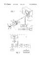
- FIG. 1is a schematic of an embodiment of an ultrasonic surgical system of the present invention
- FIG. 2is a schematic of a power source of the system
- FIG. 3is a schematic of an alternate embodiment of an aspiration system.
- One embodiment of the present inventionis an ultrasonic surgical system which has a feedback loop that varies a power provided to an ultrasonically driven handpiece in response to a change in vacuum pressure within an aspiration line.
- the systemincludes a pressure sensor which can sense the vacuum pressure within the aspiration line.
- the ultrasonically driven handpieceis driven by a power source that is also connected to the pressure sensor.
- the power sourcevaries the power output of the handpiece in response to changes in the vacuum pressure in a continuous non-step manner.
- the output power of the handpieceis increased when there is a reduction in the vacuum pressure.
- the variation in powermay be a linear function of the change in vacuum pressure, so that the power continuously increases or decreases with a corresponding reduction or increase in vacuum pressure, respectively.
- Increasing the power in response to a reduction in line pressuremay provide an automatic means for breaking tip occlusions.
- the continuous power responsecan provide a technique which has a lower average power than systems in the prior art. The lower power minimizes the amount of heat generated by friction between a cornea and a vibrating tip of the handpiece.
- FIG. 1shows an embodiment of an ultrasonic surgical system 10 of the present invention.
- the system 10may include an ultrasonically driven handpiece 12 which has a tip 14 that can be inserted into a cornea 16 .
- the handpiece 12may include one or more ultrasonic transducers 18 which convert electrical power into mechanical movement of the tip 14 .
- the handpiece 12is typically held by a surgeon who performs a surgical procedure with the system 10 .
- the system 10can be used to perform a phacoemulsification procedure to break and aspirate a lens of the cornea 16 .
- the handpiece 14is coupled to a pump 20 by an aspiration line 22 .
- the pump 20creates a vacuum pressure within the aspiration line 22 .
- the aspiration line 22is in fluid communication with an inner channel 24 and opening 26 in the tip 14 .
- the vacuum pressure within the line 22can aspirate matter from the cornea 16 .
- the system 10may include a power source 28 which provides electrical power to the transducers 18 .
- the power source 28may be connected to a pressure sensor 30 that senses the level of the vacuum pressure within the aspiration line 22 .
- the power source 28varies the output power of the transducers 18 in response to changes in the vacuum pressure within the line 22 .
- the power source 28increases the output power of the transducers 18 when the vacuum pressure falls (eg. becomes more negative) and decreases the output power when the line pressure increases.
- the power source 28may be located within a console 32 that is connected to the sensor 30 and handpiece 12 .
- the console 32may have input knobs or buttons 34 which allow the surgeon to vary different parameters of the system 10 .
- the console 32may also have a readout display(s) 35 which provides an indication of the vacuum pressure, power level, etc. of the system 10 .
- FIG. 2shows an embodiment of the power source 28 .
- the power source 28may include a microprocessor 36 that varies the output power of the transducers 18 in accordance with a software routine(s).
- the processor 36can be connected to a memory device(s) 38 which contains instructions and data used to perform the software routine.
- the processor 36may be connected to the pressure sensor 30 which provides a signal that may vary in amplitude with changes in the line pressure.
- the signalmay be converted to a digital bit string(s) by an analog to digital (A/D) converter 40 .
- A/Danalog to digital
- the output of the processor 36may be connected to a voltage controlled oscillator (VCO) 42 .
- the output of the VCO 42may be a time varying analog signal which is amplified by a driver circuit 44 and provided to the transducers 18 .
- the output signal of the VCO 42may be a series of square wave pulse.
- the frequency of the VCO output signalmay vary with a corresponding change in the amplitude of the VCO input signal from the processor 36 .
- the processor 36may have a digital to analog (D/A) converter 46 to convert a digital bit string(s) to an analog VCO input signal.
- D/Adigital to analog
- the output of the power source 28may be normally set at a frequency that is greater than the natural resonant frequency of the transducers 18 .
- the output power of the handpiece 12can be increased by decreasing the frequency of the output signal provided to the transducers 18 .
- the lower frequencyis closer to the natural frequency of the transducers 18 .
- the transfer function of the transducers 18increases as the input frequency approaches the natural frequency.
- the power output of the transducers 18decreases with an increase in the frequency of the VCO output signal. The variation in frequency may occur while the voltage of the VCO output signal remains at a constant valve.
- the software routine performed by the microprocessor 36can have an upper CEILING power limit and a lower IDLE power limit for the handpiece 12 .
- the CEILING and IDLE limitscan be varied by the surgeon through the input buttons 34 .
- the IDLE power limitmay be a minimum output power of the transducers 18 when there is a zero vacuum pressure within the aspiration line 22 .
- the CEILING power limitmay be a maximum output power of the transducers 18 .
- the processor 36may have an automatic scaling function which sets a power scale between the IDLE and CEILING limits based on the value of the CEILING limit set by the surgeon.
- the scalemay be linear so that there is a linear correspondence between the vacuum pressure and the output power of the transducers 18 .
- the processor 36may have a timer function which automatically reduces the CEILING limit to the IDLE limit if the system 10 is in the CEILING mode for a predetermined time interval.
- the processor 36may have a counter which counts each time the system enters the CEILING mode. If the timer times out, the processor 36 places the system in the IDLE mode. The timer prevents the system from staying indefinitely in the high powered CEILING mode. The time interval can be set by the surgeon through the input buttons 34 .
- the processor 36may also implement a delay function so that there is a time delay between a variation in the vacuum pressure and the change in the transducer power.
- the time delaymay be implemented as a gradual variation in transducer power over time for each change in vacuum pressure.
- the time delaymay be selectable and variable so that the surgeon can vary a delay slope defined by the change in transducer power versus a variation in the vacuum pressure.
- the delay functionprevents instantaneous feedback which can create an unstable system.
- a surgeonmay insert the tip 14 into a cornea 16 to break and aspirate a lens.
- the vibratory movement of the tip 14can break the lens into pieces which are then aspirated through the line 22 .
- An occlusion at the tip opening 26will lower the pressure within the aspiration line 22 .
- the lower line pressureis sensed by the sensor 30 and will cause the processor 36 to increase the power output of the transducers 18 .
- the increase in transducer powermay assist in breaking the occlusion.
- An occlusionmay occur with the line 22 . Such an event may cause the system to enter the CEILING mode. If the occlusion remains in the line 22 for a predetermined time interval the processor 36 may reduce the transducer power to the IDLE mode.
- FIG. 3shows an alternate embodiment of an aspiration system 100 that can automatically control the vacuum pressure within an aspiration line 102 .
- the apsiration line 102may be connected to a handpiece 104 .
- the handpiece 104may be the same or similar to the device shown in FIG. 1 and described above.
- the aspiration line 102may provide a conduit between the handpiece 104 and a pump 106 .
- the pump 106may create a vacuum pressure in the line 102 that pulls fluid and debris from the handpiece 104 .
- the pump 106may be a non-invasive peristaltic pump unit.
- the aspiration system 100may further have a pressure sensor 108 that is coupled to the aspiration line 102 by a sensor line 110 and a one-way check valve 112 .
- the one-way check valve 112will allow fluid to flow from the sensor line 110 to the aspiration line 102 , but will not allow fluid to flow from the aspiration line 102 to the sensor line 110 .
- the oneway check valve 112essentially seals the pressure sensor 108 from the aspiration line. With such an arrangement the pressure sensor 108 does not have to be sterilized after each surgical procedure.
- the system 100may further have a control valve 114 that can be switched between a closed position and an open position. In the open position the control valve 114 allows a positive pressure fluid to flow into the sensor line 110 .
- the pressure of the fluid within the sensor line 110is greater than the vacuum pressure within the aspiration line 102 .
- the differential pressure between the fluid within the sensor line 110 and the vacuum pressure within the aspiration line 102opens the check valve 112 .
- the opened check valveallows the fluid within the sensor line 110 to flow into the aspiration line 102 and increase the vacuum pressure within the line 102 .
- the control valve 114can be connected to atmosphere, a tank of fluid, or other source of positive pressure.
- the aspiration system 100may include a control circuit 116 that can switch the control valve 114 and regulate the vacuum pressure within the aspiration line 102 .
- the control circuit 116may include a comparator 118 that has a first input 120 which receives a sensor output signal from the pressure sensor 108 and a second input 122 that receives a threshold voltage signal.
- the comparator 118has an output 124 that provides a control output signal to the control valve 114 .
- the control output signalswitches the control valve 114 from the closed position to the open position to allow fluid to flow into the aspiration line 102 through the check valve 112 .
- the second input 122 of the comparator 118may be connected to an input device such as a foot pedal 126 .
- the foot pedal 126can be depressed by the surgeon to vary the amplitude of the threshold voltage signal.
- the threshold voltage signalcan also be used to control the power of the handpiece 104 .
- a direct connection to the foot pedal 126is shown and described, it is to be understood that the second input 122 may be connected to a microprocessor.
- the microprocessormay also provide the function of the comparator 118 and generate the output signal that switches the control valve 114 .
- the surgeoncan depress the foot pedal to power the handpiece 104 .
- Depressing the foot pedalalso sets the threshold voltage provided to the comparator 118 .
- the pressure transducer 108provides a sensor output signal that corresponds to the pressure within the sensor line 110 .
- the pressure within the sensor line 110is approximately equal to the vacuum pressure within the aspiration line 102 .
- An occlusionwill cause a reduction in the pressure within the aspiration line 102 .
- the decrease in pressure within the aspiration line 102creates a pressure differential that opens the check valve 112 and allows fluid to flow from the sensor line 110 and reduce the pressure in the line 110 .
- the reduction in the sensor line 110 pressurecreates a corresponding variation in the amplitude of the sensor output signal provided to the comparator 118 .
- the comparator 124provides an output signal that opens the control valve 114 .
- the opened control valveallows fluid to flow into the sensor 110 line, through the check valve 112 and into the aspiration line 102 to increase the pressure within the line 102 .
- the instantaneous flow of fluid through the open control valve 114will increase the pressure within the sensor line 110 and vary the output of the pressure sensor 108 so that it no longer exceeds the threshold voltage.
- the polarity of the output signal from the comparator 118reverses and closes the control valve 114 .
- the pressure within the sensor line 110drops until the comparator again provides an output signal that opens the control valve 114 . This cycle is repeated until the steady state output signal of the pressure sensor no longer exceeds the threshold voltage.
- the control circuit 116may include a timer circuit 128 that opens the control valve 114 and resets the system to the initial condition if the comparator 118 does not provide an valve open output signal for a predetermined time interval.
- the threshold signalmay have a preset value that defines a preset vacuum pressure.
- the surgeoncan vary vacuum pressure of the aspiration line 102 by manipulating the foot pedal 126 and varying the amplitude of the threshold signal provided to the comparator 118 .
- the systemcan be configured to operate in a “vacuum up” mode or a “vacuum down” mode. In the vacuum down mode depressing the foot pedal 126 will increase the power to the handpiece 104 and lower the pressure within the aspiration line 102 . In the vacuum up mode depressing the foot pedal will increase the power to the handpiece 104 and increase the pressure within the line 102 .
- the vacuum up modecan be enabled by inverting the threshold signal provided to the comparator 118 . The modes can be switched through a switch or button (not shown).
- the present inventionprovides a system that allows a surgeon to control the power to the handpiece and the vacuum pressure of the aspiration system through a single foot pedal 126 . This reduces the complexity of operating the system. Additionally, the check valve 112 essentially seals the pressure sensor 108 so that the sensor 108 does not have to be sterilized after each procedure.
Landscapes
- Health & Medical Sciences (AREA)
- Heart & Thoracic Surgery (AREA)
- Veterinary Medicine (AREA)
- Vascular Medicine (AREA)
- Engineering & Computer Science (AREA)
- Biomedical Technology (AREA)
- Ophthalmology & Optometry (AREA)
- Life Sciences & Earth Sciences (AREA)
- Animal Behavior & Ethology (AREA)
- General Health & Medical Sciences (AREA)
- Public Health (AREA)
- Anesthesiology (AREA)
- Nuclear Medicine, Radiotherapy & Molecular Imaging (AREA)
- Hematology (AREA)
- Surgery (AREA)
- External Artificial Organs (AREA)
Abstract
Description
Claims (17)
Priority Applications (1)
| Application Number | Priority Date | Filing Date | Title |
|---|---|---|---|
| US09/372,476US6425883B1 (en) | 1998-05-08 | 1999-08-11 | Method and apparatus for controlling vacuum as a function of ultrasonic power in an ophthalmic phaco aspirator |
Applications Claiming Priority (3)
| Application Number | Priority Date | Filing Date | Title |
|---|---|---|---|
| US8485298P | 1998-05-08 | 1998-05-08 | |
| US9709998A | 1998-06-16 | 1998-06-16 | |
| US09/372,476US6425883B1 (en) | 1998-05-08 | 1999-08-11 | Method and apparatus for controlling vacuum as a function of ultrasonic power in an ophthalmic phaco aspirator |
Related Parent Applications (1)
| Application Number | Title | Priority Date | Filing Date |
|---|---|---|---|
| US9709998AContinuation-In-Part | 1998-05-08 | 1998-06-16 |
Publications (1)
| Publication Number | Publication Date |
|---|---|
| US6425883B1true US6425883B1 (en) | 2002-07-30 |
Family
ID=26771506
Family Applications (1)
| Application Number | Title | Priority Date | Filing Date |
|---|---|---|---|
| US09/372,476Expired - Fee RelatedUS6425883B1 (en) | 1998-05-08 | 1999-08-11 | Method and apparatus for controlling vacuum as a function of ultrasonic power in an ophthalmic phaco aspirator |
Country Status (1)
| Country | Link |
|---|---|
| US (1) | US6425883B1 (en) |
Cited By (43)
| Publication number | Priority date | Publication date | Assignee | Title |
|---|---|---|---|---|
| US20040065622A1 (en)* | 2002-10-02 | 2004-04-08 | Ferguson Gary William | Filter device to capture a desired amount of material and methods of use |
| US20040069714A1 (en)* | 2002-10-11 | 2004-04-15 | Ferguson Gary William | Filter apparatus and methods to capture a desired amount of material from a sample suspension for monolayer deposition, analysis or other uses |
| US20050025646A1 (en)* | 2003-07-30 | 2005-02-03 | Vance Products Inc. D/B/A Cook Urological Incorporated | Foot pedal medical irrigation system |
| US6884252B1 (en)* | 2000-04-04 | 2005-04-26 | Circuit Tree Medical, Inc. | Low frequency cataract fragmenting device |
| US20060058729A1 (en)* | 2004-09-16 | 2006-03-16 | Alex Urich | Aspiration system for medical devices |
| US20060200068A1 (en)* | 2002-10-21 | 2006-09-07 | Advanced Medical Optics, Inc. | Novel enhanced microburst ultrasonic power delivery system and method |
| US20060212037A1 (en)* | 2005-03-16 | 2006-09-21 | Alcon, Inc. | Pumping chamber for a liquefaction handpiece |
| US20060212039A1 (en)* | 2005-03-16 | 2006-09-21 | Alcon, Inc. | Pumping chamber for a liquefaction handpiece |
| US20070071610A1 (en)* | 2003-11-20 | 2007-03-29 | Michael Holzemer | Method for controlling the drive motor of a positive displacement vaccum pump |
| US20070073309A1 (en)* | 1997-01-22 | 2007-03-29 | Advanced Medical Optics, Inc. | Control of pulse duty cycle based upon footswitch displacement |
| US20070149881A1 (en)* | 2005-12-22 | 2007-06-28 | Rabin Barry H | Ultrasonically Powered Medical Devices and Systems, and Methods and Uses Thereof |
| US20070219494A1 (en)* | 2006-03-20 | 2007-09-20 | Gao Shawn X | Surgical cassette with bubble separating structure |
| US20080033342A1 (en)* | 2006-08-01 | 2008-02-07 | Advanced Medical Optics, Inc. | Vacuum sense control for phaco pulse shaping |
| US20080233053A1 (en)* | 2005-02-07 | 2008-09-25 | Pharmalight Inc. | Method and Device for Ophthalmic Administration of Active Pharmaceutical Ingredients |
| US20080312594A1 (en)* | 2007-06-13 | 2008-12-18 | Dana Llc | Vacuum surge suppressor for surgical aspiration systems |
| WO2008157674A1 (en)* | 2007-06-19 | 2008-12-24 | Yablon, Jay, R. | Post-occlusion chamber collapse canceling system for a surgical apparatus and method of use |
| US20090032123A1 (en)* | 2007-07-31 | 2009-02-05 | Bourne John M | Check Valve |
| US20090032121A1 (en)* | 2007-07-31 | 2009-02-05 | Chon James Y | Check Valve |
| US20090043365A1 (en)* | 2005-07-18 | 2009-02-12 | Kolis Scientific, Inc. | Methods, apparatuses, and systems for reducing intraocular pressure as a means of preventing or treating open-angle glaucoma |
| US20100076471A1 (en)* | 2008-09-25 | 2010-03-25 | Bourne John M | Spring-Less Check Valve For A Handpiece |
| WO2010086741A1 (en)* | 2009-01-30 | 2010-08-05 | Lma Urology Limited | Medical device |
| US7842005B2 (en) | 2002-10-21 | 2010-11-30 | Abbott Medical Optics, Inc. | System and method for pulsed ultrasonic power delivery employing cavitational effects |
| US7857783B2 (en) | 1997-01-22 | 2010-12-28 | Abbott Medical Optics Inc. | Micro-burst ultrasonic power delivery |
| US20110054508A1 (en)* | 2009-08-31 | 2011-03-03 | Jiansheng Zhou | Pneumatic Pressure Output Control by Drive Valve Duty Cycle Calibration |
| US20110144813A1 (en)* | 2009-12-10 | 2011-06-16 | Daryush Agahi | Systems and Methods for Dynamic FeedForward |
| US20110144675A1 (en)* | 2009-12-10 | 2011-06-16 | Gao Shawn X | Systems and Methods for Dynamic Pneumatic Valve Driver |
| US8020565B2 (en) | 2002-10-21 | 2011-09-20 | Abbott Medical Optics, Inc. | Modulated pulsed ultrasonic power delivery system and method |
| US20110257614A1 (en)* | 2007-06-13 | 2011-10-20 | Dana Llc | Vacuum surge suppressor for surgical aspiration systems |
| USD698019S1 (en) | 2013-03-05 | 2014-01-21 | Alcon Research, Ltd. | Ophthalmic surgical cassette |
| US20140163454A1 (en)* | 2012-12-10 | 2014-06-12 | Alcon Research, Ltd. | Vacuum control method for surgical hand piece |
| US8821524B2 (en) | 2010-05-27 | 2014-09-02 | Alcon Research, Ltd. | Feedback control of on/off pneumatic actuators |
| US9050627B2 (en) | 2011-09-02 | 2015-06-09 | Abbott Medical Optics Inc. | Systems and methods for ultrasonic power measurement and control of phacoemulsification systems |
| US9060841B2 (en) | 2011-08-31 | 2015-06-23 | Alcon Research, Ltd. | Enhanced flow vitrectomy probe |
| US9445831B2 (en) | 2012-09-27 | 2016-09-20 | Nico Corporation | Variable aspiration control device |
| US9549851B2 (en) | 2015-01-28 | 2017-01-24 | Novartis Ag | Surgical hand piece with integrated pressure sensor |
| US9549850B2 (en) | 2013-04-26 | 2017-01-24 | Novartis Ag | Partial venting system for occlusion surge mitigation |
| US9561321B2 (en) | 2011-12-08 | 2017-02-07 | Alcon Research, Ltd. | Selectively moveable valve elements for aspiration and irrigation circuits |
| US9925314B2 (en) | 2009-08-05 | 2018-03-27 | Rocin Laboratories, Inc. | Method of performing intra-abdominal tissue aspiration to ameliorate the metabolic syndrome, or abdominal obesity |
| US10070990B2 (en) | 2011-12-08 | 2018-09-11 | Alcon Research, Ltd. | Optimized pneumatic drive lines |
| US10342564B2 (en) | 2012-09-27 | 2019-07-09 | Nico Corporation | Variable aspiration control device |
| US11259862B2 (en) | 2009-08-05 | 2022-03-01 | Rocin Laboratories, Inc. | Coaxial-driven tissue aspiration instrument system |
| US20230201443A1 (en)* | 2021-12-28 | 2023-06-29 | Johnson & Johnson Surgical Vision, Inc. | Pulse width modulation (pwm) operated vacuum relief valve in conjunction with an anti-vacuum surge (avs) module |
| US11877953B2 (en) | 2019-12-26 | 2024-01-23 | Johnson & Johnson Surgical Vision, Inc. | Phacoemulsification apparatus |
Citations (68)
| Publication number | Priority date | Publication date | Assignee | Title |
|---|---|---|---|---|
| US1206126A (en) | 1911-11-16 | 1916-11-28 | John A Mitsch | Vacuum-generator. |
| US3301063A (en) | 1964-12-10 | 1967-01-31 | Schlumberger Well Surv Corp | Pressure recorder |
| US3476144A (en) | 1968-02-02 | 1969-11-04 | Coastal Dynamics Corp | Saliva ejector shut-off device for dental units |
| US3501959A (en) | 1969-02-11 | 1970-03-24 | Stewart Warner Corp | Pressure sensing apparatus |
| US3661144A (en) | 1968-09-17 | 1972-05-09 | Hans Gram | Suction apparatus for body cavities |
| US3784039A (en) | 1972-01-10 | 1974-01-08 | Illinois Tool Works | Nursing bottle construction and assembly |
| US3812855A (en) | 1971-12-15 | 1974-05-28 | Surgical Design Corp | System for controlling fluid and suction pressure |
| US3863504A (en) | 1973-03-09 | 1975-02-04 | American Hospital Supply Corp | Pressure gauge protector assembly and method |
| US4016882A (en) | 1975-03-05 | 1977-04-12 | Cavitron Corporation | Neurosonic aspirator and method |
| US4226124A (en) | 1979-04-02 | 1980-10-07 | Baxter Travenol Laboratories, Inc. | Pressure isolator |
| US4382442A (en) | 1978-04-24 | 1983-05-10 | Jones James W | Thoracostomy pump-tube apparatus |
| US4425115A (en) | 1977-12-19 | 1984-01-10 | Wuchinich David G | Ultrasonic resonant vibrator |
| US4457455A (en) | 1981-10-13 | 1984-07-03 | Philip Meshberg | Collapsible container |
| US4465470A (en) | 1982-06-04 | 1984-08-14 | Kelman Charles D | Apparatus for and method of irrigating and aspirating an eye |
| US4468217A (en) | 1982-07-09 | 1984-08-28 | Kuzmick Kenneth M | Surgical suction tip with filter |
| US4526593A (en) | 1983-04-04 | 1985-07-02 | International Business Machines Corporation | Restrictor plug device with filter for a gas supply system |
| US4650461A (en) | 1985-06-10 | 1987-03-17 | Woods Randall L | Extracapasular cortex irrigation and extraction |
| EP0251694A2 (en) | 1986-07-02 | 1988-01-07 | Sherwood Medical Company | Medical suction device |
| US4722350A (en)* | 1984-09-21 | 1988-02-02 | Armeniades C D | Ophthalmic instrument for measuring intraocular fluid pressure |
| US4770654A (en)* | 1985-09-26 | 1988-09-13 | Alcon Laboratories Inc. | Multimedia apparatus for driving powered surgical instruments |
| EP0284322A2 (en) | 1987-03-24 | 1988-09-28 | Niko Surgical Limited | Solid matter filter for a surgical suction service |
| WO1988010102A1 (en) | 1987-06-22 | 1988-12-29 | Silvio Iannuzzi | Saliva sucking spout for dentist apparatus free from bacterium and virus infection risk |
| US4808154A (en) | 1983-10-26 | 1989-02-28 | Freeman Jerre M | Phacoemulsification/irrigation and aspiration sleeve apparatus |
| US4832685A (en) | 1985-06-05 | 1989-05-23 | Coopervision, Inc. | Fluid flow control system and connecting fitting therefor |
| US4838853A (en) | 1987-02-05 | 1989-06-13 | Interventional Technologies Inc. | Apparatus for trimming meniscus |
| US4935005A (en) | 1985-06-05 | 1990-06-19 | Nestle, S.A. | Opthalmic fluid flow control system |
| US4983160A (en) | 1985-09-27 | 1991-01-08 | Nestle S.A. | Rigid transparent fluid conduit for ophthalmic surgical irrigation |
| US5111971A (en) | 1989-05-26 | 1992-05-12 | Robert Winer | Self-pressurized container having a convoluted liner and an elastomeric sleeve |
| US5123903A (en) | 1989-08-10 | 1992-06-23 | Medical Products Development, Inc. | Disposable aspiration sleeve for ultrasonic lipectomy |
| US5152746A (en) | 1990-04-30 | 1992-10-06 | Zimmer, Inc. | Low pressure irrigation system |
| US5167725A (en) | 1990-08-01 | 1992-12-01 | Ultracision, Inc. | Titanium alloy blade coupler coated with nickel-chrome for ultrasonic scalpel |
| US5188102A (en) | 1990-05-11 | 1993-02-23 | Sumitomo Bakelite Company Limited | Surgical ultrasonic horn |
| US5197485A (en) | 1991-10-15 | 1993-03-30 | Pilling Co. | Method and apparatus for sampling aortic plaque |
| US5282786A (en) | 1991-09-23 | 1994-02-01 | Alcon Surgical, Inc. | Infusion sleeve for surgical ultrasonic apparatus |
| US5312329A (en) | 1993-04-07 | 1994-05-17 | Valleylab Inc. | Piezo ultrasonic and electrosurgical handpiece |
| US5324299A (en) | 1992-02-03 | 1994-06-28 | Ultracision, Inc. | Ultrasonic scalpel blade and methods of application |
| US5324297A (en) | 1989-01-31 | 1994-06-28 | Advanced Osseous Technologies, Inc. | Ultrasonic tool connector |
| US5342380A (en) | 1992-02-20 | 1994-08-30 | Hood Larry L | Ultrasonic knife |
| US5354268A (en) | 1992-11-04 | 1994-10-11 | Medical Instrument Development Laboratories, Inc. | Methods and apparatus for control of vacuum and pressure for surgical procedures |
| US5354265A (en) | 1992-12-30 | 1994-10-11 | Mackool Richard J | Fluid infusion sleeve |
| US5380274A (en) | 1991-01-11 | 1995-01-10 | Baxter International Inc. | Ultrasound transmission member having improved longitudinal transmission properties |
| US5391144A (en)* | 1990-02-02 | 1995-02-21 | Olympus Optical Co., Ltd. | Ultrasonic treatment apparatus |
| US5413578A (en) | 1989-03-14 | 1995-05-09 | Zahedi; Amir | Device for removing a bone cement tube |
| US5454784A (en) | 1994-06-10 | 1995-10-03 | Zimmer, Inc. | Control valve for a fluid set |
| US5464389A (en) | 1993-08-10 | 1995-11-07 | Stahl; Norman O. | Working tip for fragmenting and aspirating ocular tissue |
| US5582588A (en) | 1993-04-19 | 1996-12-10 | Olympus Optical Co., Ltd. | Ultrasonic therapeutic apparatus |
| US5591127A (en) | 1994-01-28 | 1997-01-07 | Barwick, Jr.; Billie J. | Phacoemulsification method and apparatus |
| US5628743A (en) | 1994-12-21 | 1997-05-13 | Valleylab Inc. | Dual mode ultrasonic surgical apparatus |
| US5630939A (en) | 1995-09-15 | 1997-05-20 | Imtec Corporation | Filter assembly device for use in surgical aspirated suction |
| US5676650A (en) | 1994-12-20 | 1997-10-14 | Grieshaber & Co. Ag Schaffhausen | Ophthalmologic aspiration and irrigation system, and method of operating same |
| US5685840A (en)* | 1993-02-16 | 1997-11-11 | Danek Medical, Inc. | Method and apparatus for minimally invasive tissue removal |
| US5722945A (en) | 1990-07-17 | 1998-03-03 | Aziz Yehia Anis | Removal of tissue |
| US5730156A (en) | 1996-07-10 | 1998-03-24 | Mackool; Richard J. | Method for cutting and removing wrapping from an intraocular lens implant within an eye |
| US5733256A (en) | 1996-09-26 | 1998-03-31 | Micro Medical Devices | Integrated phacoemulsification system |
| US5743871A (en) | 1995-06-02 | 1998-04-28 | Surgical Design Corporation | Phacoemulsification handpiece, sleeve, and tip |
| US5746719A (en) | 1996-10-25 | 1998-05-05 | Arthur D. Little, Inc. | Fluid flow control system incorporating a disposable pump cartridge |
| US5766146A (en) | 1996-04-04 | 1998-06-16 | Allergan | Method of infusion control during phacoemulsification surgery |
| US5807310A (en) | 1997-05-13 | 1998-09-15 | Nexus Medical System, Inc. Llc | Irrigation sleeve for an ultrasonic tip |
| US5810765A (en) | 1994-06-30 | 1998-09-22 | Nidek Company, Ltd. | Irrigation/aspiration apparatus |
| US5817099A (en) | 1996-06-06 | 1998-10-06 | Skolik; Stephanie A. | Universal port/seal device for ocular surgery |
| US5843021A (en) | 1994-05-09 | 1998-12-01 | Somnus Medical Technologies, Inc. | Cell necrosis apparatus |
| US5890516A (en) | 1996-08-12 | 1999-04-06 | Talamonti; Anthony R. | Stomach suction pump connector valve |
| US5897569A (en) | 1997-04-16 | 1999-04-27 | Ethicon Endo-Surgery, Inc. | Ultrasonic generator with supervisory control circuitry |
| EP0931519A1 (en) | 1995-07-18 | 1999-07-28 | Atrion Medical Products, Inc. | Autogenous bone specimen collector |
| US6083193A (en) | 1998-03-10 | 2000-07-04 | Allergan Sales, Inc. | Thermal mode phaco apparatus and method |
| US6110259A (en) | 1997-11-21 | 2000-08-29 | Jlj International, Inc. | Smoke evacuation system |
| US6193683B1 (en) | 1999-07-28 | 2001-02-27 | Allergan | Closed loop temperature controlled phacoemulsification system to prevent corneal burns |
| US6203540B1 (en) | 1998-05-28 | 2001-03-20 | Pearl I, Llc | Ultrasound and laser face-lift and bulbous lysing device |
- 1999
- 1999-08-11USUS09/372,476patent/US6425883B1/ennot_activeExpired - Fee Related
Patent Citations (72)
| Publication number | Priority date | Publication date | Assignee | Title |
|---|---|---|---|---|
| US1206126A (en) | 1911-11-16 | 1916-11-28 | John A Mitsch | Vacuum-generator. |
| US3301063A (en) | 1964-12-10 | 1967-01-31 | Schlumberger Well Surv Corp | Pressure recorder |
| US3476144A (en) | 1968-02-02 | 1969-11-04 | Coastal Dynamics Corp | Saliva ejector shut-off device for dental units |
| US3661144A (en) | 1968-09-17 | 1972-05-09 | Hans Gram | Suction apparatus for body cavities |
| US3501959A (en) | 1969-02-11 | 1970-03-24 | Stewart Warner Corp | Pressure sensing apparatus |
| US3812855A (en) | 1971-12-15 | 1974-05-28 | Surgical Design Corp | System for controlling fluid and suction pressure |
| US3784039A (en) | 1972-01-10 | 1974-01-08 | Illinois Tool Works | Nursing bottle construction and assembly |
| US3863504A (en) | 1973-03-09 | 1975-02-04 | American Hospital Supply Corp | Pressure gauge protector assembly and method |
| US4016882A (en) | 1975-03-05 | 1977-04-12 | Cavitron Corporation | Neurosonic aspirator and method |
| US4425115A (en) | 1977-12-19 | 1984-01-10 | Wuchinich David G | Ultrasonic resonant vibrator |
| US4382442A (en) | 1978-04-24 | 1983-05-10 | Jones James W | Thoracostomy pump-tube apparatus |
| US4226124A (en) | 1979-04-02 | 1980-10-07 | Baxter Travenol Laboratories, Inc. | Pressure isolator |
| US4457455A (en) | 1981-10-13 | 1984-07-03 | Philip Meshberg | Collapsible container |
| US4465470A (en) | 1982-06-04 | 1984-08-14 | Kelman Charles D | Apparatus for and method of irrigating and aspirating an eye |
| US4468217A (en) | 1982-07-09 | 1984-08-28 | Kuzmick Kenneth M | Surgical suction tip with filter |
| US4526593A (en) | 1983-04-04 | 1985-07-02 | International Business Machines Corporation | Restrictor plug device with filter for a gas supply system |
| US4808154A (en) | 1983-10-26 | 1989-02-28 | Freeman Jerre M | Phacoemulsification/irrigation and aspiration sleeve apparatus |
| US4722350A (en)* | 1984-09-21 | 1988-02-02 | Armeniades C D | Ophthalmic instrument for measuring intraocular fluid pressure |
| US4935005A (en) | 1985-06-05 | 1990-06-19 | Nestle, S.A. | Opthalmic fluid flow control system |
| US4832685A (en) | 1985-06-05 | 1989-05-23 | Coopervision, Inc. | Fluid flow control system and connecting fitting therefor |
| US4650461A (en) | 1985-06-10 | 1987-03-17 | Woods Randall L | Extracapasular cortex irrigation and extraction |
| US4770654A (en)* | 1985-09-26 | 1988-09-13 | Alcon Laboratories Inc. | Multimedia apparatus for driving powered surgical instruments |
| US4983160A (en) | 1985-09-27 | 1991-01-08 | Nestle S.A. | Rigid transparent fluid conduit for ophthalmic surgical irrigation |
| EP0251694A2 (en) | 1986-07-02 | 1988-01-07 | Sherwood Medical Company | Medical suction device |
| US4838853A (en) | 1987-02-05 | 1989-06-13 | Interventional Technologies Inc. | Apparatus for trimming meniscus |
| EP0284322A2 (en) | 1987-03-24 | 1988-09-28 | Niko Surgical Limited | Solid matter filter for a surgical suction service |
| WO1988010102A1 (en) | 1987-06-22 | 1988-12-29 | Silvio Iannuzzi | Saliva sucking spout for dentist apparatus free from bacterium and virus infection risk |
| US5324297A (en) | 1989-01-31 | 1994-06-28 | Advanced Osseous Technologies, Inc. | Ultrasonic tool connector |
| US5413578A (en) | 1989-03-14 | 1995-05-09 | Zahedi; Amir | Device for removing a bone cement tube |
| US5111971A (en) | 1989-05-26 | 1992-05-12 | Robert Winer | Self-pressurized container having a convoluted liner and an elastomeric sleeve |
| US5111971B1 (en) | 1989-05-26 | 1993-07-06 | Winer Robert | |
| US5123903A (en) | 1989-08-10 | 1992-06-23 | Medical Products Development, Inc. | Disposable aspiration sleeve for ultrasonic lipectomy |
| US5391144A (en)* | 1990-02-02 | 1995-02-21 | Olympus Optical Co., Ltd. | Ultrasonic treatment apparatus |
| US5152746A (en) | 1990-04-30 | 1992-10-06 | Zimmer, Inc. | Low pressure irrigation system |
| US5188102A (en) | 1990-05-11 | 1993-02-23 | Sumitomo Bakelite Company Limited | Surgical ultrasonic horn |
| US5722945A (en) | 1990-07-17 | 1998-03-03 | Aziz Yehia Anis | Removal of tissue |
| US5167725A (en) | 1990-08-01 | 1992-12-01 | Ultracision, Inc. | Titanium alloy blade coupler coated with nickel-chrome for ultrasonic scalpel |
| US5380274A (en) | 1991-01-11 | 1995-01-10 | Baxter International Inc. | Ultrasound transmission member having improved longitudinal transmission properties |
| US5282786A (en) | 1991-09-23 | 1994-02-01 | Alcon Surgical, Inc. | Infusion sleeve for surgical ultrasonic apparatus |
| US5197485A (en) | 1991-10-15 | 1993-03-30 | Pilling Co. | Method and apparatus for sampling aortic plaque |
| US5324299A (en) | 1992-02-03 | 1994-06-28 | Ultracision, Inc. | Ultrasonic scalpel blade and methods of application |
| US5342380A (en) | 1992-02-20 | 1994-08-30 | Hood Larry L | Ultrasonic knife |
| US5354268A (en) | 1992-11-04 | 1994-10-11 | Medical Instrument Development Laboratories, Inc. | Methods and apparatus for control of vacuum and pressure for surgical procedures |
| US5520652A (en) | 1992-11-04 | 1996-05-28 | Medical Instrument Development Laboratories, Inc. | Methods and apparatus for control of vacuum and pressure for surgical procedures |
| US5354265A (en) | 1992-12-30 | 1994-10-11 | Mackool Richard J | Fluid infusion sleeve |
| US5685840A (en)* | 1993-02-16 | 1997-11-11 | Danek Medical, Inc. | Method and apparatus for minimally invasive tissue removal |
| US5312329A (en) | 1993-04-07 | 1994-05-17 | Valleylab Inc. | Piezo ultrasonic and electrosurgical handpiece |
| US5582588A (en) | 1993-04-19 | 1996-12-10 | Olympus Optical Co., Ltd. | Ultrasonic therapeutic apparatus |
| US5464389A (en) | 1993-08-10 | 1995-11-07 | Stahl; Norman O. | Working tip for fragmenting and aspirating ocular tissue |
| US5591127A (en) | 1994-01-28 | 1997-01-07 | Barwick, Jr.; Billie J. | Phacoemulsification method and apparatus |
| US5700240A (en) | 1994-01-28 | 1997-12-23 | Barwick, Jr.; Billie John | Phacoemulsification system having ultrasonic power controlled by aspiration vacuum sensor |
| US5843021A (en) | 1994-05-09 | 1998-12-01 | Somnus Medical Technologies, Inc. | Cell necrosis apparatus |
| US6179803B1 (en) | 1994-05-09 | 2001-01-30 | Somnus Medical Technologies, Inc. | Cell necrosis apparatus |
| US5454784A (en) | 1994-06-10 | 1995-10-03 | Zimmer, Inc. | Control valve for a fluid set |
| US5810765A (en) | 1994-06-30 | 1998-09-22 | Nidek Company, Ltd. | Irrigation/aspiration apparatus |
| US5676650A (en) | 1994-12-20 | 1997-10-14 | Grieshaber & Co. Ag Schaffhausen | Ophthalmologic aspiration and irrigation system, and method of operating same |
| US5628743A (en) | 1994-12-21 | 1997-05-13 | Valleylab Inc. | Dual mode ultrasonic surgical apparatus |
| US5743871A (en) | 1995-06-02 | 1998-04-28 | Surgical Design Corporation | Phacoemulsification handpiece, sleeve, and tip |
| EP0931519A1 (en) | 1995-07-18 | 1999-07-28 | Atrion Medical Products, Inc. | Autogenous bone specimen collector |
| US5630939A (en) | 1995-09-15 | 1997-05-20 | Imtec Corporation | Filter assembly device for use in surgical aspirated suction |
| US5766146A (en) | 1996-04-04 | 1998-06-16 | Allergan | Method of infusion control during phacoemulsification surgery |
| US5817099A (en) | 1996-06-06 | 1998-10-06 | Skolik; Stephanie A. | Universal port/seal device for ocular surgery |
| US5730156A (en) | 1996-07-10 | 1998-03-24 | Mackool; Richard J. | Method for cutting and removing wrapping from an intraocular lens implant within an eye |
| US5890516A (en) | 1996-08-12 | 1999-04-06 | Talamonti; Anthony R. | Stomach suction pump connector valve |
| US5733256A (en) | 1996-09-26 | 1998-03-31 | Micro Medical Devices | Integrated phacoemulsification system |
| US5746719A (en) | 1996-10-25 | 1998-05-05 | Arthur D. Little, Inc. | Fluid flow control system incorporating a disposable pump cartridge |
| US5897569A (en) | 1997-04-16 | 1999-04-27 | Ethicon Endo-Surgery, Inc. | Ultrasonic generator with supervisory control circuitry |
| US5807310A (en) | 1997-05-13 | 1998-09-15 | Nexus Medical System, Inc. Llc | Irrigation sleeve for an ultrasonic tip |
| US6110259A (en) | 1997-11-21 | 2000-08-29 | Jlj International, Inc. | Smoke evacuation system |
| US6083193A (en) | 1998-03-10 | 2000-07-04 | Allergan Sales, Inc. | Thermal mode phaco apparatus and method |
| US6203540B1 (en) | 1998-05-28 | 2001-03-20 | Pearl I, Llc | Ultrasound and laser face-lift and bulbous lysing device |
| US6193683B1 (en) | 1999-07-28 | 2001-02-27 | Allergan | Closed loop temperature controlled phacoemulsification system to prevent corneal burns |
Cited By (91)
| Publication number | Priority date | Publication date | Assignee | Title |
|---|---|---|---|---|
| US9788998B2 (en) | 1997-01-22 | 2017-10-17 | Abbott Medical Optics Inc. | Control of pulse duty cycle based upon footswitch displacement |
| US20070073309A1 (en)* | 1997-01-22 | 2007-03-29 | Advanced Medical Optics, Inc. | Control of pulse duty cycle based upon footswitch displacement |
| US7857783B2 (en) | 1997-01-22 | 2010-12-28 | Abbott Medical Optics Inc. | Micro-burst ultrasonic power delivery |
| US8876747B2 (en) | 1997-01-22 | 2014-11-04 | Abbott Medical Optics Inc. | Micro-burst ultrasonic power delivery |
| US8197436B2 (en) | 1997-01-22 | 2012-06-12 | Abbott Medical Optics Inc. | Micro-burst ultrasonic power delivery |
| US8195286B2 (en) | 1997-01-22 | 2012-06-05 | Abbott Medical Optics Inc. | Control of pulse duty cycle based upon footswitch displacement |
| US20110160646A1 (en)* | 1997-01-22 | 2011-06-30 | Abbott Medical Optics Inc. | Micro-burst ultrasonic power delivery |
| US6884252B1 (en)* | 2000-04-04 | 2005-04-26 | Circuit Tree Medical, Inc. | Low frequency cataract fragmenting device |
| US20050189286A1 (en)* | 2002-10-02 | 2005-09-01 | Ferguson Gary W. | Filter device to capture a desired amount of material and methods of use |
| US6884341B2 (en) | 2002-10-02 | 2005-04-26 | G6 Science Corp. | Filter device to capture a desired amount of material |
| US20040065622A1 (en)* | 2002-10-02 | 2004-04-08 | Ferguson Gary William | Filter device to capture a desired amount of material and methods of use |
| US6905594B2 (en) | 2002-10-11 | 2005-06-14 | G6 Science Corp. | Filter apparatus and methods to capture a desired amount of material from a sample suspension for monolayer deposition, analysis or other uses |
| US20040069714A1 (en)* | 2002-10-11 | 2004-04-15 | Ferguson Gary William | Filter apparatus and methods to capture a desired amount of material from a sample suspension for monolayer deposition, analysis or other uses |
| US8945162B2 (en) | 2002-10-21 | 2015-02-03 | Abbott Medical Optics Inc. | System and method for pulsed ultrasonic power delivery employing cavitational effects |
| US7842005B2 (en) | 2002-10-21 | 2010-11-30 | Abbott Medical Optics, Inc. | System and method for pulsed ultrasonic power delivery employing cavitational effects |
| US20110077583A1 (en)* | 2002-10-21 | 2011-03-31 | Abbott Medical Optics Inc. | System and method for pulsed ultrasonic power delivery employing cavitational effects |
| US8887735B2 (en) | 2002-10-21 | 2014-11-18 | Abbott Medical Optics Inc. | Modulated pulsed ultrasonic power delivery system and method |
| US9642745B2 (en) | 2002-10-21 | 2017-05-09 | Abbott Medical Optics Inc. | Modulated pulsed ultrasonic power delivery system and method |
| US7938120B2 (en) | 2002-10-21 | 2011-05-10 | Abbott Medical Optics, Inc. | Enhanced microburst ultrasonic power delivery system and method |
| US9707127B2 (en) | 2002-10-21 | 2017-07-18 | Abbott Medical Optics Inc. | Modulated pulsed ultrasonic power delivery system and method |
| US20150216726A1 (en)* | 2002-10-21 | 2015-08-06 | Abbott Medical Optics Inc. | System and method for pulsed ultrasonic power delivery employing cavitation effects |
| US8852138B2 (en) | 2002-10-21 | 2014-10-07 | Abbott Medical Optics Inc. | Modulated pulsed ultrasound power delivery system and method |
| US10765557B2 (en) | 2002-10-21 | 2020-09-08 | Johnson & Johnson Surgical Vision, Inc. | Modulated pulsed ultrasonic power delivery system and method |
| US20060200068A1 (en)* | 2002-10-21 | 2006-09-07 | Advanced Medical Optics, Inc. | Novel enhanced microburst ultrasonic power delivery system and method |
| US8231564B2 (en) | 2002-10-21 | 2012-07-31 | Abbott Medical Optics Inc. | Modulated pulsed ultrasonic power delivery system and method |
| US10245179B2 (en)* | 2002-10-21 | 2019-04-02 | Johnson & Johnson Surgical Vision, Inc. | System and method for pulsed ultrasonic power delivery employing cavitation effects |
| US8020565B2 (en) | 2002-10-21 | 2011-09-20 | Abbott Medical Optics, Inc. | Modulated pulsed ultrasonic power delivery system and method |
| US20050025646A1 (en)* | 2003-07-30 | 2005-02-03 | Vance Products Inc. D/B/A Cook Urological Incorporated | Foot pedal medical irrigation system |
| US20070071610A1 (en)* | 2003-11-20 | 2007-03-29 | Michael Holzemer | Method for controlling the drive motor of a positive displacement vaccum pump |
| US20060058729A1 (en)* | 2004-09-16 | 2006-03-16 | Alex Urich | Aspiration system for medical devices |
| US8475402B2 (en) | 2004-09-16 | 2013-07-02 | Data, LLC | Aspiration system for medical devices |
| US20080233053A1 (en)* | 2005-02-07 | 2008-09-25 | Pharmalight Inc. | Method and Device for Ophthalmic Administration of Active Pharmaceutical Ingredients |
| US20060212037A1 (en)* | 2005-03-16 | 2006-09-21 | Alcon, Inc. | Pumping chamber for a liquefaction handpiece |
| US7758585B2 (en) | 2005-03-16 | 2010-07-20 | Alcon, Inc. | Pumping chamber for a liquefaction handpiece |
| US20060212039A1 (en)* | 2005-03-16 | 2006-09-21 | Alcon, Inc. | Pumping chamber for a liquefaction handpiece |
| US9913678B2 (en) | 2005-07-18 | 2018-03-13 | Tearscience, Inc. | Methods, apparatuses, and systems for reducing intraocular pressure as a means of preventing or treating open-angle glaucoma |
| US20090043365A1 (en)* | 2005-07-18 | 2009-02-12 | Kolis Scientific, Inc. | Methods, apparatuses, and systems for reducing intraocular pressure as a means of preventing or treating open-angle glaucoma |
| US20070149881A1 (en)* | 2005-12-22 | 2007-06-28 | Rabin Barry H | Ultrasonically Powered Medical Devices and Systems, and Methods and Uses Thereof |
| US20070219494A1 (en)* | 2006-03-20 | 2007-09-20 | Gao Shawn X | Surgical cassette with bubble separating structure |
| US7604615B2 (en)* | 2006-03-20 | 2009-10-20 | Alcon, Inc. | Surgical cassette with bubble separating structure |
| US8034067B2 (en) | 2006-08-01 | 2011-10-11 | Abbott Medical Optics Inc. | Vacuum sense control for phaco pulse shaping |
| US8366728B2 (en) | 2006-08-01 | 2013-02-05 | Abbott Medical Optics Inc. | Vacuum sense control for phaco pulse shaping |
| US7998156B2 (en) | 2006-08-01 | 2011-08-16 | Abbott Medical Optics Inc. | Vacuum sense control for phaco pulse shaping |
| US9226849B2 (en)* | 2006-08-01 | 2016-01-05 | Abbott Medical Optics Inc. | Vacuum sense control for phaco pulse shaping |
| WO2008016870A3 (en)* | 2006-08-01 | 2008-03-27 | Advanced Medical Optics Inc | Vacuum sense control for phaco pulse shaping |
| US20140018724A1 (en)* | 2006-08-01 | 2014-01-16 | Abbott Medical Optics Inc. | Vacuum sense control for phaco pulse shaping |
| US20100114010A1 (en)* | 2006-08-01 | 2010-05-06 | Abbott Medical Optics Inc. | Vacuum sense control for phaco pulse shaping |
| US20100114009A1 (en)* | 2006-08-01 | 2010-05-06 | Abbott Medical Optics Inc. | Vacuum sense control for phaco pulse shaping |
| US7785336B2 (en) | 2006-08-01 | 2010-08-31 | Abbott Medical Optics Inc. | Vacuum sense control for phaco pulse shaping |
| US8202287B2 (en) | 2006-08-01 | 2012-06-19 | Abbott Medical Optics Inc. | Vacuum sense control for phaco pulse shaping |
| US20080033342A1 (en)* | 2006-08-01 | 2008-02-07 | Advanced Medical Optics, Inc. | Vacuum sense control for phaco pulse shaping |
| US7914482B2 (en) | 2007-06-13 | 2011-03-29 | Dana Llc | Vacuum surge suppressor for surgical aspiration systems |
| WO2008156996A1 (en)* | 2007-06-13 | 2008-12-24 | Dana, Llc | Vacuum surge suppressor for surgical aspiration systems |
| US8753323B2 (en)* | 2007-06-13 | 2014-06-17 | Dana, LLC. | Vacuum surge suppressor for surgical aspiration systems |
| US20110257614A1 (en)* | 2007-06-13 | 2011-10-20 | Dana Llc | Vacuum surge suppressor for surgical aspiration systems |
| US20080312594A1 (en)* | 2007-06-13 | 2008-12-18 | Dana Llc | Vacuum surge suppressor for surgical aspiration systems |
| WO2008157674A1 (en)* | 2007-06-19 | 2008-12-24 | Yablon, Jay, R. | Post-occlusion chamber collapse canceling system for a surgical apparatus and method of use |
| US8617106B2 (en)* | 2007-06-19 | 2013-12-31 | Alcon Research, Ltd. | Post-occlusion chamber collapse canceling system for a surgical apparatus and method of use |
| US20100185150A1 (en)* | 2007-06-19 | 2010-07-22 | Jaime Zacharias | Post-Occlusion Chamber Collapse Canceling System For A Surgical Apparatus and Method of Use |
| US20090032123A1 (en)* | 2007-07-31 | 2009-02-05 | Bourne John M | Check Valve |
| US7849875B2 (en) | 2007-07-31 | 2010-12-14 | Alcon, Inc. | Check valve |
| US20090032121A1 (en)* | 2007-07-31 | 2009-02-05 | Chon James Y | Check Valve |
| US8291933B2 (en) | 2008-09-25 | 2012-10-23 | Novartis Ag | Spring-less check valve for a handpiece |
| US20100076471A1 (en)* | 2008-09-25 | 2010-03-25 | Bourne John M | Spring-Less Check Valve For A Handpiece |
| WO2010086741A1 (en)* | 2009-01-30 | 2010-08-05 | Lma Urology Limited | Medical device |
| US9925314B2 (en) | 2009-08-05 | 2018-03-27 | Rocin Laboratories, Inc. | Method of performing intra-abdominal tissue aspiration to ameliorate the metabolic syndrome, or abdominal obesity |
| US11259862B2 (en) | 2009-08-05 | 2022-03-01 | Rocin Laboratories, Inc. | Coaxial-driven tissue aspiration instrument system |
| US12171482B2 (en) | 2009-08-05 | 2024-12-24 | Rocin Laboratories, Inc. | Bariatric surgery operating room with a laparoscopic-based visceral fat tissue aspiration system configured and operational for treating metabolic syndrome in human patients on an ambulatory basis |
| US12178494B2 (en) | 2009-08-05 | 2024-12-31 | Rocin Laboratories, Inc | Laparoscopic-based method of safely removing visceral fat tissue deposits from within the mesenteric region of a human patient suffering from metabolic syndrome |
| US8818564B2 (en) | 2009-08-31 | 2014-08-26 | Alcon Research, Ltd. | Pneumatic pressure output control by drive valve duty cycle calibration |
| US20110054508A1 (en)* | 2009-08-31 | 2011-03-03 | Jiansheng Zhou | Pneumatic Pressure Output Control by Drive Valve Duty Cycle Calibration |
| US20110144675A1 (en)* | 2009-12-10 | 2011-06-16 | Gao Shawn X | Systems and Methods for Dynamic Pneumatic Valve Driver |
| US8666556B2 (en) | 2009-12-10 | 2014-03-04 | Alcon Research, Ltd. | Systems and methods for dynamic feedforward |
| US8728108B2 (en) | 2009-12-10 | 2014-05-20 | Alcon Research, Ltd. | Systems and methods for dynamic pneumatic valve driver |
| US20110144813A1 (en)* | 2009-12-10 | 2011-06-16 | Daryush Agahi | Systems and Methods for Dynamic FeedForward |
| US8821524B2 (en) | 2010-05-27 | 2014-09-02 | Alcon Research, Ltd. | Feedback control of on/off pneumatic actuators |
| US9060841B2 (en) | 2011-08-31 | 2015-06-23 | Alcon Research, Ltd. | Enhanced flow vitrectomy probe |
| US9050627B2 (en) | 2011-09-02 | 2015-06-09 | Abbott Medical Optics Inc. | Systems and methods for ultrasonic power measurement and control of phacoemulsification systems |
| US9561321B2 (en) | 2011-12-08 | 2017-02-07 | Alcon Research, Ltd. | Selectively moveable valve elements for aspiration and irrigation circuits |
| US10070990B2 (en) | 2011-12-08 | 2018-09-11 | Alcon Research, Ltd. | Optimized pneumatic drive lines |
| US9788850B2 (en) | 2012-09-27 | 2017-10-17 | Nico Corporation | Variable aspiration control device |
| US10342564B2 (en) | 2012-09-27 | 2019-07-09 | Nico Corporation | Variable aspiration control device |
| US9445831B2 (en) | 2012-09-27 | 2016-09-20 | Nico Corporation | Variable aspiration control device |
| US9878075B2 (en)* | 2012-12-10 | 2018-01-30 | Alcon Research, Ltd. | Vacuum control method for surgical hand piece |
| US20140163454A1 (en)* | 2012-12-10 | 2014-06-12 | Alcon Research, Ltd. | Vacuum control method for surgical hand piece |
| USD698019S1 (en) | 2013-03-05 | 2014-01-21 | Alcon Research, Ltd. | Ophthalmic surgical cassette |
| US9549850B2 (en) | 2013-04-26 | 2017-01-24 | Novartis Ag | Partial venting system for occlusion surge mitigation |
| US9549851B2 (en) | 2015-01-28 | 2017-01-24 | Novartis Ag | Surgical hand piece with integrated pressure sensor |
| US11877953B2 (en) | 2019-12-26 | 2024-01-23 | Johnson & Johnson Surgical Vision, Inc. | Phacoemulsification apparatus |
| US20230201443A1 (en)* | 2021-12-28 | 2023-06-29 | Johnson & Johnson Surgical Vision, Inc. | Pulse width modulation (pwm) operated vacuum relief valve in conjunction with an anti-vacuum surge (avs) module |
| US12427239B2 (en)* | 2021-12-28 | 2025-09-30 | Johnson & Johnson Surgical Vision, Inc. | Pulse width modulation (PWM) operated vacuum relief valve in conjunction with an anti-vacuum surge (AVS) module |
Similar Documents
| Publication | Publication Date | Title |
|---|---|---|
| US6425883B1 (en) | Method and apparatus for controlling vacuum as a function of ultrasonic power in an ophthalmic phaco aspirator | |
| US11877952B2 (en) | Selectively moveable valve elements for aspiration and irrigation circuits | |
| US6179808B1 (en) | Method of controlling the operating parameters of a surgical system | |
| US10940039B2 (en) | Automatic ultrasonic phacoemulsification control | |
| EP1187643B1 (en) | Irrigation control system | |
| US8814821B2 (en) | System and method for modulated surgical procedure irrigation and aspiration | |
| CA2559501C (en) | Method of controlling a surgical system based on a rate of change of an operating parameter | |
| US10342701B2 (en) | Systems and methods for phacoemulsification with vacuum based pumps | |
| CA2559749C (en) | Method of controlling a surgical system based on a load on the cutting tip of a handpiece | |
| CA2559499C (en) | Method of controlling a surgical system based on irrigation flow | |
| JP3561227B2 (en) | Control method of lens ultrasonic suction device | |
| EP1285642A1 (en) | Apparatus and software for controlling an intraoperative temperature | |
| KR20040049767A (en) | Non-linear flow restrictor for a medical aspiration system | |
| AU4258400A (en) | Liquid venting surgical system and cassette | |
| EP2320842B1 (en) | Device for ophthalmic surgery, in particular for cataract removal, provided with a system for dynamically maintaining intraocular pressure | |
| MXPA02003105A (en) | Method of controlling intraocular pressure and temperature. |
Legal Events
| Date | Code | Title | Description |
|---|---|---|---|
| AS | Assignment | Owner name:CIRCUIT TREE MEDICAL, INC., CALIFORNIA Free format text:ASSIGNMENT OF ASSIGNORS INTEREST;ASSIGNORS:URICH, ALEX;CURTIS, MICHAEL;REEL/FRAME:010166/0751 Effective date:19990804 | |
| FPAY | Fee payment | Year of fee payment:4 | |
| AS | Assignment | Owner name:WELLS FARGO BANK, NATIONAL ASSOCIATION,CALIFORNIA Free format text:SECURITY AGREEMENT;ASSIGNOR:STAAR SURGICAL COMPANY;REEL/FRAME:017846/0278 Effective date:20060608 Owner name:WELLS FARGO BANK, NATIONAL ASSOCIATION, CALIFORNIA Free format text:SECURITY AGREEMENT;ASSIGNOR:STAAR SURGICAL COMPANY;REEL/FRAME:017846/0278 Effective date:20060608 | |
| FEPP | Fee payment procedure | Free format text:PAYOR NUMBER ASSIGNED (ORIGINAL EVENT CODE: ASPN); ENTITY STATUS OF PATENT OWNER: SMALL ENTITY | |
| REMI | Maintenance fee reminder mailed | ||
| FPAY | Fee payment | Year of fee payment:8 | |
| SULP | Surcharge for late payment | Year of fee payment:7 | |
| REMI | Maintenance fee reminder mailed | ||
| LAPS | Lapse for failure to pay maintenance fees | ||
| STCH | Information on status: patent discontinuation | Free format text:PATENT EXPIRED DUE TO NONPAYMENT OF MAINTENANCE FEES UNDER 37 CFR 1.362 | |
| FP | Lapsed due to failure to pay maintenance fee | Effective date:20140730 |