US6425005B1 - Method and apparatus for managing local resources at service nodes in an intelligent network - Google Patents
Method and apparatus for managing local resources at service nodes in an intelligent networkDownload PDFInfo
- Publication number
- US6425005B1 US6425005B1US09/420,654US42065499AUS6425005B1US 6425005 B1US6425005 B1US 6425005B1US 42065499 AUS42065499 AUS 42065499AUS 6425005 B1US6425005 B1US 6425005B1
- Authority
- US
- United States
- Prior art keywords
- service
- status
- node
- execution environment
- local execution
- Prior art date
- Legal status (The legal status is an assumption and is not a legal conclusion. Google has not performed a legal analysis and makes no representation as to the accuracy of the status listed.)
- Expired - Lifetime
Links
- 238000000034methodMethods0.000titleclaimsdescription149
- 238000012545processingMethods0.000claimsabstractdescription94
- 238000004891communicationMethods0.000claimsabstractdescription35
- 230000007246mechanismEffects0.000claimsabstractdescription7
- 230000000977initiatory effectEffects0.000claimsabstractdescription5
- 238000007726management methodMethods0.000claimsdescription57
- 238000003860storageMethods0.000claimsdescription16
- 230000004044responseEffects0.000claimsdescription11
- 238000013500data storageMethods0.000claimsdescription10
- 230000008859changeEffects0.000claimsdescription5
- 230000008569processEffects0.000description100
- 230000006870functionEffects0.000description86
- LZCOQTDXKCNBEE-XJMZPCNVSA-NN-methylscopolamineChemical compoundC1([C@@H](CO)C(=O)OC2C[C@@H]3[N+]([C@H](C2)[C@@H]2[C@H]3O2)(C)C)=CC=CC=C1LZCOQTDXKCNBEE-XJMZPCNVSA-N0.000description23
- 238000013523data managementMethods0.000description14
- 239000004744fabricSubstances0.000description14
- 230000011664signalingEffects0.000description12
- 238000013519translationMethods0.000description12
- 238000012544monitoring processMethods0.000description11
- 238000010586diagramMethods0.000description10
- 238000012360testing methodMethods0.000description9
- 230000008901benefitEffects0.000description8
- 238000005516engineering processMethods0.000description8
- 238000011161developmentMethods0.000description7
- 230000000875corresponding effectEffects0.000description6
- 230000004913activationEffects0.000description5
- 238000012986modificationMethods0.000description5
- 230000004048modificationEffects0.000description5
- 230000002085persistent effectEffects0.000description5
- 230000005540biological transmissionEffects0.000description4
- 238000001038ionspray mass spectrometryMethods0.000description4
- 238000012423maintenanceMethods0.000description4
- 230000002093peripheral effectEffects0.000description4
- 238000007792additionMethods0.000description3
- 238000013459approachMethods0.000description3
- 238000009826distributionMethods0.000description3
- 230000003993interactionEffects0.000description3
- 230000003213activating effectEffects0.000description2
- 230000036541healthEffects0.000description2
- 238000013507mappingMethods0.000description2
- 230000005055memory storageEffects0.000description2
- 238000005457optimizationMethods0.000description2
- 230000010076replicationEffects0.000description2
- 238000012546transferMethods0.000description2
- HRANPRDGABOKNQ-ORGXEYTDSA-N(1r,3r,3as,3br,7ar,8as,8bs,8cs,10as)-1-acetyl-5-chloro-3-hydroxy-8b,10a-dimethyl-7-oxo-1,2,3,3a,3b,7,7a,8,8a,8b,8c,9,10,10a-tetradecahydrocyclopenta[a]cyclopropa[g]phenanthren-1-yl acetateChemical compoundC1=C(Cl)C2=CC(=O)[C@@H]3C[C@@H]3[C@]2(C)[C@@H]2[C@@H]1[C@@H]1[C@H](O)C[C@@](C(C)=O)(OC(=O)C)[C@@]1(C)CC2HRANPRDGABOKNQ-ORGXEYTDSA-N0.000description1
- 241001133287Artocarpus hirsutusSpecies0.000description1
- 241001522296Erithacus rubeculaSpecies0.000description1
- VLQGDKKHHCKIOJ-UHFFFAOYSA-NNNOSChemical compoundNNOSVLQGDKKHHCKIOJ-UHFFFAOYSA-N0.000description1
- 230000006399behaviorEffects0.000description1
- 210000004556brainAnatomy0.000description1
- 230000005465channelingEffects0.000description1
- 229940052810complex bDrugs0.000description1
- 230000002596correlated effectEffects0.000description1
- 230000000593degrading effectEffects0.000description1
- 230000003111delayed effectEffects0.000description1
- 230000001419dependent effectEffects0.000description1
- 238000004090dissolutionMethods0.000description1
- RGNPBRKPHBKNKX-UHFFFAOYSA-NhexaflumuronChemical compoundC1=C(Cl)C(OC(F)(F)C(F)F)=C(Cl)C=C1NC(=O)NC(=O)C1=C(F)C=CC=C1FRGNPBRKPHBKNKX-UHFFFAOYSA-N0.000description1
- 230000006872improvementEffects0.000description1
- 230000010354integrationEffects0.000description1
- 230000002452interceptive effectEffects0.000description1
- 238000005304joiningMethods0.000description1
- 230000007257malfunctionEffects0.000description1
- 239000011159matrix materialSubstances0.000description1
- 230000003287optical effectEffects0.000description1
- 230000000644propagated effectEffects0.000description1
- 238000004904shorteningMethods0.000description1
- 238000000638solvent extractionMethods0.000description1
- 238000001228spectrumMethods0.000description1
- 239000013589supplementSubstances0.000description1
- 230000001360synchronised effectEffects0.000description1
- 238000010200validation analysisMethods0.000description1
Images


Classifications
- H—ELECTRICITY
- H04—ELECTRIC COMMUNICATION TECHNIQUE
- H04M—TELEPHONIC COMMUNICATION
- H04M15/00—Arrangements for metering, time-control or time indication ; Metering, charging or billing arrangements for voice wireline or wireless communications, e.g. VoIP
- H04M15/90—Arrangements for metering, time-control or time indication ; Metering, charging or billing arrangements for voice wireline or wireless communications, e.g. VoIP using Intelligent Networks [IN] or Advanced Intelligent Networks [AIN]
- H—ELECTRICITY
- H04—ELECTRIC COMMUNICATION TECHNIQUE
- H04M—TELEPHONIC COMMUNICATION
- H04M15/00—Arrangements for metering, time-control or time indication ; Metering, charging or billing arrangements for voice wireline or wireless communications, e.g. VoIP
- H—ELECTRICITY
- H04—ELECTRIC COMMUNICATION TECHNIQUE
- H04M—TELEPHONIC COMMUNICATION
- H04M3/00—Automatic or semi-automatic exchanges
- H04M3/22—Arrangements for supervision, monitoring or testing
- H04M3/2254—Arrangements for supervision, monitoring or testing in networks
- H04M3/2263—Network management
- H—ELECTRICITY
- H04—ELECTRIC COMMUNICATION TECHNIQUE
- H04M—TELEPHONIC COMMUNICATION
- H04M3/00—Automatic or semi-automatic exchanges
- H04M3/42—Systems providing special services or facilities to subscribers
- H04M3/42136—Administration or customisation of services
- H—ELECTRICITY
- H04—ELECTRIC COMMUNICATION TECHNIQUE
- H04M—TELEPHONIC COMMUNICATION
- H04M3/00—Automatic or semi-automatic exchanges
- H04M3/42—Systems providing special services or facilities to subscribers
- H04M3/4228—Systems providing special services or facilities to subscribers in networks
- H—ELECTRICITY
- H04—ELECTRIC COMMUNICATION TECHNIQUE
- H04Q—SELECTING
- H04Q3/00—Selecting arrangements
- H04Q3/0016—Arrangements providing connection between exchanges
- H04Q3/0029—Provisions for intelligent networking
- H—ELECTRICITY
- H04—ELECTRIC COMMUNICATION TECHNIQUE
- H04Q—SELECTING
- H04Q3/00—Selecting arrangements
- H04Q3/0016—Arrangements providing connection between exchanges
- H04Q3/0029—Provisions for intelligent networking
- H04Q3/0037—Provisions for intelligent networking involving call modelling techniques, e.g. modifications to the basic call state model [BCSM]
- H—ELECTRICITY
- H04—ELECTRIC COMMUNICATION TECHNIQUE
- H04Q—SELECTING
- H04Q3/00—Selecting arrangements
- H04Q3/0016—Arrangements providing connection between exchanges
- H04Q3/0029—Provisions for intelligent networking
- H04Q3/0054—Service creation techniques
- H04Q3/0058—Service creation techniques using service-independent building blocks (SIBBs) or "primitives"
- H—ELECTRICITY
- H04—ELECTRIC COMMUNICATION TECHNIQUE
- H04M—TELEPHONIC COMMUNICATION
- H04M2201/00—Electronic components, circuits, software, systems or apparatus used in telephone systems
- H04M2201/54—Object oriented software
- H—ELECTRICITY
- H04—ELECTRIC COMMUNICATION TECHNIQUE
- H04M—TELEPHONIC COMMUNICATION
- H04M2203/00—Aspects of automatic or semi-automatic exchanges
- H04M2203/05—Aspects of automatic or semi-automatic exchanges related to OAM&P
- H04M2203/052—Aspects of automatic or semi-automatic exchanges related to OAM&P software update
- H—ELECTRICITY
- H04—ELECTRIC COMMUNICATION TECHNIQUE
- H04M—TELEPHONIC COMMUNICATION
- H04M2207/00—Type of exchange or network, i.e. telephonic medium, in which the telephonic communication takes place
- H04M2207/12—Type of exchange or network, i.e. telephonic medium, in which the telephonic communication takes place intelligent networks
- H—ELECTRICITY
- H04—ELECTRIC COMMUNICATION TECHNIQUE
- H04M—TELEPHONIC COMMUNICATION
- H04M2215/00—Metering arrangements; Time controlling arrangements; Time indicating arrangements
- H04M2215/01—Details of billing arrangements
- H04M2215/016—Billing using Intelligent Networks [IN] or Advanced Intelligent Networks [AIN]
Definitions
- the present inventionis related generally to Intelligent Networks, and, more particularly, to a novel system and methodology for managing service processing resources employed for performing services in response to service requests received at service nodes of an intelligent network.
- a network serviceis a function performed by a communications network, such as data or telephony, and its associated resources in response to an interaction with one or more subscribers.
- a telephony network resident servicesuch as call forwarding or voice mail access
- Other network servicesmay be directed at assisting a network owner with security, validation, and authentication. Adding or modifying a service requires changes to be made in the communications network.
- Switchesare controlled by integrated or imbedded processors operated by proprietary software or firmware designed by the switch manufacturer.
- the switch manufacturer's software or firmwaremust support all functional aspects of service processing, call processing, facility processing and network management. This means that when a network owner wishes to implement a new service or modify an existing service, the software of every switch in the network must be revised by the various switch manufacturers.
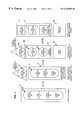
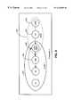
- a monolithic switchwhich is denoted generally as 20 , contains service processing functions 22 , call processing functions 24 , facility processing functions 26 and a switch fabric 28 . All of these functions 22 , 24 , 26 and 28 are hard-coded, intermixed and undifferentiated, as symbolized by the group 30 . Moreover, functions 22 , 24 , 26 and 28 are designed by the switch manufacturer and operate on proprietary platforms that vary from manufacturer to manufacturer. As a result, these functions 22 , 24 , 26 and 28 cannot be modified without the aid of the manufacturer, which slows down service development and implementation, and increases the cost of bringing a new service to market. The development of new and innovative services, call processing, data processing, signal processing and network operations are, therefore, constrained by the manufacturer's control over their proprietary switch hardware and software, and the inherent difficulty of establishing and implementing industry standards.
- the service processing functions 22are encoded within the monolithic switch 20 and only allow local control of this process based on local data contents and the number dialed. This local information is interpreted by a hard-coded process engine that carries out the encoded service function.
- the call processing functions 24are hard-coded and provide call origination and call termination functions. This process actually brings up and takes down individual connections to complete a call.
- the facility processing functions 26are also hard-coded and provide all data processing relating to the physical resources involved in a call.
- the switch fabric 28represents the hardware component of the switch and the computer to run the monolithic software provided by the switch manufacturer, such as Northern Telecom, Inc.
- the switch fabric 28provides the physical facilities necessary to establish a connection and may include, but is not limited to, bearer devices (Tl's and DSO's), switching matrix devices (network planes and their processors), link layer signal processors (SS7, MTP, ISDN, LAPD) and specialized circuits (conference ports, audio tone detectors).
- bearer devicesTl's and DSO's
- switching matrix devicesnetwork planes and their processors
- link layer signal processorsSS7, MTP, ISDN, LAPD
- specialized circuitsconference ports, audio tone detectors
- SIBBService Independent Building Blocks
- the In or AIN architecturewhich is denoted generally as 40 , logically separates the functions of the monolithic switch 20 into a Service Control Point (“SCP”) 42 , and a Service Switching Point (“SSP”) and Switching System 44 .
- SCPService Control Point
- SSPService Switching Point
- the SCP 42contains the service processing functions 22
- SSP and Switching System 44contain the call processing functions 24 , facility processing functions 26 and the switch fabric 28 .
- the call processing functions 24 , facility processing functions 26 and the switch fabric 28are hard-coded, intermixed and undifferentiated, as symbolized by the group 46 .
- the Service Switching Pointis a functional module that resides at a switch in order to recognize when a subscriber's signaling requires more than simple routing based solely upon the number dialed.
- the SSPsuspends further handling of the call while it initiates a query for correct handling of the call to the remote SCP 42 , which essentially acts as a database server for a number of switches.
- This division of processingresults in the offloading of the infrequent, yet time consuming task of handling special service calls, from the switch.
- this moderate centralizationdraws a balance between having one readily modifiable, heavy burdened repository serving the whole network versus deploying a complete copy of the repository at every switch.
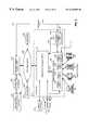
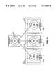
- FIG. 2a diagram of a telecommunications system employing an IN or AIN architecture is shown and is denoted generally as 50 .
- Various customer systemssuch as an ISDN terminal 52 , a first telephone 54 , and a second telephone 56 are connected to the SSP and Switching System 44 .
- the ISDN terminal 52is connected to the SSP and Switching System 44 by signaling line 60 and transport line 62 .
- the first telephone 54is connected to the SSP and Switching System 44 by transport line 64 .
- the second telephone 56is connected to a remote switching system 66 by transport line 68 and the remote switching system 66 is connected to the SSP and Switching System 44 by transport line 70 .
- the SSP 70is a functional module that resides at a switch in order to recognize when a subscriber's signaling requires more than simple routing based upon the number dialed.
- the SSP 70suspends further handling of the call while it initiates a query for correct handling of the call.
- This queryis sent in the form of SS7 messaging to a remote SCP 42 .
- the Service Control Point 42is so named because changing the database content at this location can alter the network function as it appears to subscribers connected through the many subtending switches.
- the queryis sent through signaling line 72 to the Signal Transfer Point (“STP”) 74 , which is simply a router for SS7 messaging among these elements, and then through signaling line 76 to the SCP 42 .
- STPSignal Transfer Point
- the Integrated Service Management System (“ISMS”) 78is envisioned as a management tool to deploy or alter services or to manage per-subscriber access to services.
- the ISMS 78operates mainly by altering the operating logic and data stored within the SSP 70 and SCP 42 .
- the ISMS 78has various user interfaces 80 and 82 .
- This ISMS 78is connected to the SCP 42 by operations line 84 , the SSP and Switching System 44 by operations line 86 , and the Intelligent Peripheral (“IP”) 88 by operations line 90 .
- the Intelligent Peripheral 88is a device used to add functions to the network that are not available on the switches, such as a voice response or speech recognition system.
- the IP 88is connected to the SSP and Switching System 44 by signaling line 92 and transport line 94 .
- the callis initiated when the customer picks up the receiver and begins dialing.
- the SSP 70 at the company switchmonitors the dialing and recognizes the trigger sequence.
- the SSP 70suspends further handling of the call until service logic can be consulted.
- the SSP 70then composes a standard SS7 message and sends it through STP(s) 74 to the SCP 42 .
- the SCP 42receives and decodes the message and invokes the SLP.
- the SLIinterprets the SCP, which may call for actuating other functions such as database lookup for number translation.
- the SCP 42returns an SS7 message to the SSP and Switching System 44 regarding the handling of the call or otherwise dispatches messages to the network elements to carry out the correct service.
- an SS7 messageis sent among the switches to tear down the call and call detail records are created by each switch involved in the call.
- the call detail recordsare collected, correlated, and resolved offline for each call to derive billing for toll calls thus, completing call processing.
- the IN and AIN architecturesattempt to predefine a standard set of functions to support all foreseeable services. These standard functions are all hard-coded into various state machines in the switch. Unfortunately, any new functions, which are likely to arise in conjunction with new technologies or unforeseen service needs, cannot be implemented without an extensive overhaul and testing of the network software across many vendor platforms. Furthermore, if a new function requires changes to standardized call models, protocols, or interfaces, the implementation of the service utilizing that function may be delayed until the changes are ratified by an industry standards group. But even as draft standards have attempted to broaden the set of IN and AIN supported functions, equipment suppliers have refused to endorse these draft standards due to the staggering increase in code complexity.
- SSI/SFSeparate Switch Intelligence and Switch Fabric
- the interface between the switch fabric functions 158 and switch intelligence functions 152may be extended through a communications network such that the switch fabric 158 and switch intelligence 152 may not necessarily be physically located together, by executed within the same processor, or even have a one-to-one correspondence.
- the switch intelligence 152provides a consistent interface of simple non-service-specific, non-manufacturer-specific functions common to all switches.
- An Intelligent Computing Complex (“ICC”) 160contains the service processing functions 22 and communicates with multiple switch intelligence elements 152 .
- This approachoffers the network owner advantages in flexible service implementation because all but the most elementary functions are moved outside the realm of the manufacturer-specific code. Further improvements may be realized by providing a more unified environment for the creation, development, test and execution of service logic.
- RISCReduced-Instruction Set Computing
- the present inventionis directed to a novel system and method for managing communications service resources at nodes in an intelligent network designed to perform event processing services for any type of event, e.g., telephone call, received at a resource complex or switching platform associated with nodes of an Intelligent Distributed Network which is alternately referred to as the Next Generation Intelligent Network (“NGIN”).
- the intelligent networkincludes a plurality of service nodes, each node providing an execution environment that may provide all of the call processing functionality necessary to handle a call at the instance it is received at the switch or resource complex physically associated with that particular service node.
- the networkis of a highly scalable architecture and engineered to ensure that communications services, embodied as executable logic programs (objects) capable of invocation at each service node, are deployed and managed in a cost-effective manner.
- the resource management system of the inventionparticularly is a hierarchical system that enables real-time optimization of service execution in a manner so as to increase efficiency and throughput of the intelligent network.
- Servicesembodied as service logic programs (object and object instantiations) execute locally in one or more computing environments located at a service node, with each service and computing environment having an associated system load levels.
- service objectsare locally instantiated to perform call processing services upon receipt of service requests, e.g., a call received at the network switch
- a first tier management componenttracks system loads and service usage thresholds according to the business rules, e.g., time of day, expected call demand, etc..
- a second tier management component associated with the service nodeoptimally determines whether an additional execution environment may be instantiated at that service node to perform the service at that node.
- a subset of the service status information maintained at each service of the networkis provided to a third tier management system component associated with the intelligent network.
- the servicemay be instantiated at another execution environment provided at another service node, e.g., according to pre-defined business rules. In this manner, intelligent network resources are conserved, and service provision efficiency increased.
- FIG. 1is logical representation of various switching architectures
- FIG. 2is a diagram of a telecommunications system employing a typical intelligent network configuration according to the prior art
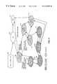
- FIG. 3is a diagram of a telecommunications system employing an intelligent distributed network architecture
- FIG. 4is a block diagram depicting an alternative embodiment of IDNA functional components configured as the Next Generation Intelligent Network
- FIG. 5illustrates conceptually the functionality of the service administration component 500 ;
- FIG. 6is a logical and functional diagram of a telecommunications system employing an intelligent distributed network architecture in accordance with the present invention
- FIG. 7is a diagram illustrating the layering of functional interfaces within an intelligent call processor in accordance with the present invention.
- FIG. 8 ( a )illustrates a preferred architecture of a service control environment 430 ;
- FIG. 8 ( b )illustrates the functional architecture of the NOS NT and LRM functional sub-components.
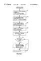
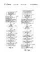
- FIG. 8 ( c )is a flow chart depicting the Service Agent functionality
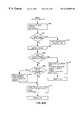
- FIG. 8 ( d )is a flow chart depicting the Thread Manager process
- FIG. 9illustrates the activation of a service via the NOS LRM component.
- FIG. 10illustrates the functional architecture of the NOS NT and LRM functional sub-components.
- FIG. 11illustrates the architecture of the resource management system for the intelligent network.
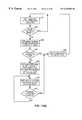
- FIG. 12 ( a )illustrates the local resource management status processor flow.
- FIG. 12 ( b )is a more detailed illustration depicting node cache status database architecture.
- FIG. 13is a flow diagram depicting an SLP instantiation process.
- FIG. 14 ( a )is a flow diagram depicting the SLEE threshold processing.
- FIG. 14 ( b )is a flow diagram depicting the SLEE monitoring process.
- FIGS. 15 ( a ) and 15 ( b )depict the three-tiered intelligent network resource management functionality.
- the present inventionis one component of a comprehensive intelligent network alternately referred to herein as an Intelligent Distributed Network Architecture (“IDNA”) or the Next Generation Intelligent Network (“NGIN”).
- IDNAIntelligent Distributed Network Architecture
- NGINNext Generation Intelligent Network
- the NGIN architectureis designed to perform intelligent call processing services for any type of call received at a resource complex or switching platform, e.g., switch, router, IP termination address, etc.
- the IDNA/NGINpreferably comprises a plurality of distributed service nodes with each node providing an execution environment providing call processing functionality necessary to handle a call at the instance it is received at the switch or resource complex physically associated with that particular service node.
- NGINis of a highly scalable architecture and engineered to ensure that executable service objects, embodied as independent Service Logic Programs (“SLP”), and associated data for performing event services, e.g., 1-800 telephone call, send fax, etc., may be deployed to and maintained at the service nodes in a cost-effective manner.
- SLPService Logic Programs
- the intelligent networksupports location and platform-independent call processing service execution independent of and transparent to the event switching platform or resource complex in which an event or call is received, and, enables high-level logic programs to be run virtually anywhere in the network independent of the service execution platform.
- the systemprovides location-independent communications among these distributed processes.
- the Intelligent Distributed Network Architecturesuch as described in commonly assigned, co-pending U.S. patent application Ser. No. 09/128,937 filed Aug. 5, 1998, still pending, entitled “Intelligent Call Platform for an Intelligent Network Distributed Architecture”, the contents and disclosure of which is incorporated by reference herein, is denoted generally as 170 .
- the present inventionunifies the ICC 160 and Switch Intelligence 152 of the SSI/SF architecture 150 into an Intelligent Call Processor (“ICP”) 172 .
- ICPIntelligent Call Processor
- the ICP 172contains the service control functions 22 , call processing functions 24 and facility processing functions 26 as managed objects in an object-oriented platform, which is symbolized by blocks 174 , 176 and 178 .
- the ICP 172is logically separated from the Resource Complex 180 .
- the Wide Area Network (“WAN”) 202is a system that supports the distribution of applications and data across a wide geographic area.
- the transport networkis based upon Synchronous Optical NETwork (“SONET”) and connects the IDNA Nodes 204 and enables the applications within those nodes to communicate with each other.
- SONETSynchronous Optical NETwork
- Each IDNA Node 204contains an Intelligent Call Processor (“ICP”) 172 and a Resource Complex 180 (FIG. 1 ).
- FIG. 3illustrates an IDNA Node 204 having a Resource Complex A (“RCA”) 206 and a Resource Complex B (“RCB”) 208 .
- the ICPcan be linked to Adjunct Processors 210 , which provide existing support functions, such as provisioning, billing and restoration, however, these functions may be absorbed by functionality provided by a Network Management System (“NMS”) 212 . In the preferred embodiment, however, these support functions may be provided by a centralized Service Administration (“SA”) system 500 having Data Management (“DM”) component 400 as will be described herein with respect to FIG. 4 . As further shown in FIG.
- SAService Administration
- DMData Management
- the ICP 172can be also linked to other ICP's 172 , other networks (not shown), or other devices (not shown) through a direct link 214 having signaling 216 and bearer links 218 .
- a direct linkprevents latency between the connected devices and allows the devices to communicate in their own language.
- the ICP 172is the “brain” of the IDNA Node 204 and is preferably a general purpose computer, which may range from a single processor with a single memory storage device to a large scale computer network depending on the processing requirements of the IDNA Node 204 .
- the general purpose computerwill have redundant processing, memory storage and connections.
- general purpose computersrefer to computers that are, or may be assembled with, commercial off-the-shelf components, as opposed to dedicated devices specifically configured and designed for telephone switching applications.
- the integration of general purpose computers within the calling networkaffords numerous advantages.
- ICP 172The use of general purpose computers gives the ICP 172 the capability of scaling up with additional hardware to meet increased processing needs. These additions include the ability to increase processing power, data storage, and communications bandwidth. These additions do not require the modification of manufacturer-specific software and/or hardware on each switch in the calling network. Consequently, new services and protocols may be implemented and installed on a global scale, without modification of individual devices in the switching network.
- monolithic switches 20FIG. 1
- intelligent call processors 172By changing from monolithic switches 20 (FIG. 1) to intelligent call processors 172 , the present invention provides the foregoing advantages and increased capabilities.
- multi-processingallows the use of less expensive processors to optimize the price/performance ratio for call processing.
- the ICP 172may, as noted above, comprise a cluster of general purpose computers operating, for example, on a UNIX or Windows NT operating system.
- the ICP 172may consist of sixteen (16) 32 bit processors operating at 333 MHz in a Symmetric Multi-Processor cluster.
- the processorscould, for example, be divided into four separate servers with four processors each.
- the individual processorswould be connected with a System Area Network (“SAN”) or other clustering technology.
- the processor clustercould share access to Redundant Array of Independent Disks (“RAID”) modular data storage devices. Shared storage may be adjusted by adding or removing the modular disk storage devices.
- the servers in the clusterswould preferably share redundant links to the RC 180 (FIG. 1 ).
- the ICP software architectureis an open processing model that allows the interchangeability of: (1) management software; (2) ICP applications; (3) computing hardware and software; (4) resource complex components; and even (5) service architecture and processing.
- Such a generic architecturereduces maintenance costs due to standardization and provides the benefits derived from economies of scale.
- the present inventionenables the partitioning of development work and the use of modular tools that result in faster development and implementation of services. Moreover, the use of and the relevant aspects of service management are within the control of the network operator on an as required basis as opposed to the constraints imposed by fixed messaging protocol or a particular combination of hardware and software supplied by a given manufacturer.
- the present inventionalso allows services and functions to be flexibly (“where you want it”) and dynamically (“on the fly”) distributed across the network based on any number of factors, such as capacity and usage. Performance is improved because service processing 22 (FIG. 1 ), call processing 24 (FIG. 1) and facility processing 26 (FIG. 1) operate in a homogeneous platform.
- the present inventionallows the monitoring and manipulation of call sub-elements that could not be accessed before.
- the present inventionalso provides for monitoring the usage of functions or services so that when they are outdated or unused they can be eliminated.
- the Resource Complex (“RC”) 180(FIG. 1) is a collection of physical devices, or resources, that provide bearer, signaling and connection services.
- the RC 180which can include Intelligent Peripherals 88 , replaces the switch fabric 28 and 158 (FIG. 1) of the IN or AIN or SSI/SF architecture.
- the control of the Resource Complex, such as RCA 206is at a lower level.
- the RCA 206can contain more than one switch fabric 158 .
- the switch fabrics 158 or other customer interfaces(not shown) connect to multiple subscribers and switching networks via standard telephony connections. These customer systems may include ISDN terminals 52 , fax machines 220 , telephones 54 , and PBX systems 222 .
- the ICP 172controls and communicates with the RC 180 (FIG. 1 ), RCA 206 and RCB 208 through a high speed data communications pipe (minimally 100 Mb/sec Ethernet connection) 224 .
- the RC 180 , 206 and 208can be analogized to a printer and ICP 172 can be analogized to a personal computer wherein the personal computer uses a driver to control the printer.
- the “driver” in the IDNA Node 204is a Resource Complex Proxy (“RCP”) (not shown), which will be described below in reference to FIG. 6 . This allows manufacturers to provide an IDNA compliant node using this interface without having to rewrite all of their software to incorporate IDNA models.
- RCPResource Complex Proxy
- the control of the Resource Complex 180(FIG. 1 ), RCA 206 and RCB 208 , is at a lower level than typically provided by the AIN or IN architecture.
- resource complex manufacturersonly have to provide a single interface to support facility and network management processing; they do not have to provide the network owner with specific call and service processing.
- a low level interfaceis abstracted into more discrete operations. Having a single interface allows the network owner to choose from a wide spectrum of Resource Complex manufacturers, basing decisions on price and performance.
- Intelligenceis added to the ICP 172 rather than the RC 180 , which isolates the RC 180 from changes and reduces its complexity. Since the role of the RC 180 is simplified, changes are more easily made, thus making it easier to migrate to alternative switching and transmission technologies, such as Asynchronous Transfer Mode (“ATM”).
- ATMAsynchronous Transfer Mode
- IPIntelligent Peripherals
- IP's 88provide the ability to process and act on information contained within the actual call transmission path.
- IP's 88are generally in a separate Resource Complex, such as RCB 208 , and are controlled by the ICP's 172 in a similar manner as RCA 206 .
- IP'scan provide the ability to process data in the actual call transmission path in real-time using Digital Signal Processing (“DSP”) technology.
- DSPDigital Signal Processing
- the Network Management System (“NMS”) 212is used to monitor and control hardware and services in the IDNA Network 200 .
- a suggested NMS 212 implementationmight be a Telecommunications Management Network (“TMN”) compliant framework which provides management of the components within the IDNA Network 200 . More specifically, the NMS 212 controls the deployment of services, maintains the health of those services, provides information about those services, and provides a network-level management function for the IDNA Network 200 .
- the NMS 212accesses and controls the services and hardware through agent functionality within the IDNA nodes 204 .
- the ICP-NMS Agent (not shown) within the IDNA Node 204carries out the commands or requests issued by the NMS 212 .
- the NMS 212can directly monitor and control RCA 206 and RCB 208 through a standard operations link 226 .
- the Managed Object Creation Environment (“MOCE”) 228includes the sub-components to create services that run in the IDNA network 200 .
- a Service Independent Building Block and API representations that a service designer uses to create new servicesare imbedded within the MOCE'S primary sub-component, a Graphical User Interface (“GUI”).
- GUIGraphical User Interface
- the MOCE 228is a unified collection of tools hosted on a single user environment or platform, alternately referred to as a Service Creation (“SC”) environment. It represents the collection of operations that are required throughout the process of service creation, such as service documentation, managed object definition, interface definition, protocol definition and data input definition, which are encapsulated in managed objects, and service testing.
- the network owneronly has to develop a service once using the MOCE 228 , because managed objects can be applied to all the nodes on his network. This is in contrast to the network owner having each of the various switch manufacturers develop their version of the service, which means that the service must be developed multiple times.
- the MOCE 228 and NMS 212are connected together via a Repository 230 .
- the Repository 230contains the managed objects that are distributed by the NMS 212 and used in the IDNA/NGIN Nodes 204 .
- the Repository 230also provides a buffer between the MOCE 228 and the NMS 212 ,
- the MOCE 228may, however, be directly connected to the NMS 212 to perform “live” network testing, which is indicated by the dashed line 232 .
- the IDNA/NGIN systemincludes a centralized Service Administration (“SA”) component 500 that provides both a storage (Repository) 230 functionality and the generic network management (NMS) 212 functionality of the IDNA system 170 together with added capabilities as described in greater detail in commonly-owned, co-pending U.S. patent application Ser. No. 09/421,590, still pending, entitled METHOD AND APPARATUS FOR DEPLOYING SERVICE MODULES AMONG SERVICE NODES DISTRIBUTED IN AN INTELLIGENT NETWORK, the contents and disclosure of which is incorporated by reference as if fully set forth herein.
- SA component 500as shown in FIG.
- DMdata management
- the Service Administration component 500is a component that performs all of the functions needed to manage, store, and distribute all services and service data used by IDNA/NGIN service processing nodes and to configure both the hardware and software components implemented in the IDNA/NGIN system.
- the Service Administration component 500is a component that performs all of the functions needed to manage, store, and distribute all services and service data used by IDNA/NGIN service processing nodes and to configure both the hardware and software components implemented in the IDNA/NGIN system.
- the SA component 500is responsible for: receiving the data from MOCE (Service Creation) 228 , receiving customer order data 502 from order entry and other legacy systems 229 to provision the IDNA/NGIN system for use by customers; deploying data, Service Independent Building Blocks (“SIBBs”), Service Logic Programs (“SLPs”), and other service components 503 , e.g., to the MOCE 200 as requested by MOCE/SCE users, for example, during the service creation process; receiving completed and tested service packages, SIBBs, SLPs or other service or data components 506 from MOCE 228 ; providing unique names to each service component; and, distributing the data and each service component 509 to a Data Management functional component 400 , to be described in greater detail herein.
- Service Administration 300maintains the repository 230 which includes a global Database of Record (“DBOR”) comprising all IDNA services and data from which the Data Management component 400 receives all of its data.
- DBORglobal Database of Record
- Service Administrationincludes: activating data and service components 512 to ensure that all data, SIBBs and managed objects or service logic programs SLPs are available for nodes via the Data Management component 400 ; registering the names of the data, SLPs and SIBBs 515 by feeding their logical names to a Network Operating System (“NOS”) component 700 , to be described in detail below, for registration therewith; deactivating data and service components 518 ; and, removing data and services 521 from the IDNA/NGIN system via the Data Management component 400 .
- Service Administrationadditionally performs a configuration management function by maintaining the state of each SIBB and service (pre-tested, post-tested, deployed, etc.), in addition to versioning through its naming process. This ensures a service is not deployed until all components of that service have been successfully tested and configured.
- the Service Administration component 500further performs the function of configuring and provisioning the IDNA/NGIN service nodes 204 in accordance with configuration information that SA receives. Particularly, based on the received configuration information, the SA component 500 determines the capabilities of each component at each service node 204 , which services and data to distribute to which nodes, which services will run on which server(s) resident at the service node, and which data will be cached to local memory resident associated with IDNA/NGIN node server(s).
- SAdeploys configuration rules contained in service profile (configuration) files 580 to a Local (node) Resource Manager (“LRM”) component 575 of the NOS system 700 for storage in a local LRM cache located at each service node.
- LRMLocal Resource Manager
- these configuration files 580determine which services to execute at an IDNA node.
- the LRMfirst reads this service profile file 580 stored in the local cache at that node, and determines a specific Service Layer Execution Environment (“SLEE”), e.g., a virtual machine, to run a service on in accordance with the rules in the service profile file and, which services are to run actively (as persistent objects) in the SLEE, or are to be instantiated only on-demand.
- SLEEService Layer Execution Environment
- the ICP 172is shown to contain an ICP-NMS Agent 240 and a SLEE 242 that, in turn, hosts a variety of managed objects 246 , 248 , 250 and 252 derived from the managed objects base class 244 .
- the ICP-NMS Agent 240provides the NMS 212 the ability to control the operation of the ICP 172 , and, as will be described, the ability to control the operation and configuration of the LOS 260 , the operation and configuration of the WANOS 262 , and the instantiation and operation of SLEE(s) 242 .
- managed objectsare a method of packaging software functions wherein each managed object offers both functional and management interfaces to implement the functions of the managed object.
- the management interfacecontrols access to who and what can access the managed object functions.
- all of the telephony application software, except for the infrastructure software, run by the IDNA/NGIN Node 204is deployed as managed objects and supporting libraries. This provides a uniform interface and implementation to control and manage the IDNA Node software.
- the collection of network elements that connect, route, and terminate bearer traffic handled by the nodewill be collectively referred to as the Resource Complex (“RC”) 180 .
- the service processing applications running on the SLEEuse the Resource Proxy (“RCP”) 244 as a control interface to the RC 180 .
- the RCP 244may be likened to a device driver in that it adapts equipment-independent commands from objects in the SLEE to equipment-specific commands to be performed by the RC 180 .
- the RCP 224can be described as an interface implementing the basic commands common among vendors of the resources in the RCP 244 .
- the RCP 244could be implemented as shown as one or more managed objects running on the IDNA node 204 . Alternatively, this function could be provided as part of the RC 180 .
- the NMS 212 , Repository 230 and MOCE 228are consistent with the description of those elements in the discussion of FIGS. 3-5.
- the operations link 226directly connects the NMS 212 to the RC 180 .
- the RC 180may be connected to other resource complexes 254 .
- a direct signaling link 214is also shown entering the ICP 172 so that signaling 216 , such as SS7, can enter the call processing environment directly. By intercepting signaling at the network periphery, the SS7 message can go directly to the ICP 172 without going through the RC 180 . This reduces latency and improves robustness by shortening the signaling path.
- An accompanying bearer line 218connects to the RC 180 .
- FIG. 7depicts the layering of functional interfaces within the ICP 172 .
- the MOCE 228is the system where the managed object software and its dependencies are generated.
- the NMS 212controls the execution of the ICP 172 by interfacing to an agent function provided within the ICP 172 , called the ICP-NMS Agent 240 .
- the NMS 212controls the operation of the Local Operating System (“LOS”) 260 on the ICP 172 .
- the NMS 212controls the operation of the ICP 172 , including starting and stopping of processes, querying the contents of the process table, and the status of processes, configuring the operating system parameters, and monitoring the performance of the general purpose computer system that hosts the ICP 172 .
- LOSLocal Operating System
- the NMS 212also controls the operation of the Wide Area Network Operating System (“WANOS”) 262 .
- the NMS 212controls the initialization and operation of the WANOS support processes and the configuration of the WANOS libraries via its control of the LOS 260 and any other interfaces provided by the NMS SLEE control.
- the NMS 212controls the instantiation and operation of the one or more SLEE's 242 running on an ICP 172 .
- the LOS 260is a commercial-off-the-shelf operating system for operation of the general purpose computer.
- the WANOS 262is a commercial-off-the-shelf middle-ware software package (e.g., an object request broker) that facilitates seamless communication between computing nodes.
- the SLEE 242hosts the execution of managed objects 244 , which are software instances that implement the service processing architecture.
- the SLEE 242implements the means to control the execution of the managed objects 244 by the ICP-NMS Agent 240 .
- a SLEE 242 instanceis a software process capable of deploying and removing managed object software, instantiating and destroying managed object instances, supporting the interaction and collaboration of managed objects, administering access to Native Libraries 264 , and interfacing with the NMS-ICP Agent 240 in implementing the required controls.
- the Native Libraries 264are libraries that are coded to depend only on the LOS 260 or WANOS 262 and the native general purpose computer execution (e.g., compiled C libraries). They are used primarily to supplement the native functionality provided by the SLEE 242 .
- SLEE libraries 266are libraries coded to execute in the SLEE 242 . They can access the functions provided by the SLEE 242 and the Native Libraries 264 .
- the managed objects 244are the software loaded and executed by the SLEE 242 . They can access the functionality provided by the SLEE 242 and the SLEE libraries 266 (and possibly the native libraries 264 ).
- the ICP-NMS Agent 240provides the NMS 212 the ability to control the operation of the ICP 172 .
- the ICP-NMS Agent 240implements the ability to control the operation and configuration of the LOS 260 , the operation and configuration of the WANOS 262 , and the instantiation and operation of SLEE(s) 242 .
- the proposed service processing architectureoperates in layers of increasing abstraction.
- the managed object layer 244which is the layer of objects (software instances) that are interaction under the control of the NMS 212 ; and the Library layer 264 or 266 , which is the layer of software (either native to the SLEE 242 or the LOS 260 ) that supplies supplementary functions to the operation of the managed objects 242 or the SLEE 242 itself.
- NOSNetwork Operating System
- LOSLOS
- WANOSWANOS
- ICP-NMS Agent functionalitymay be represented as a Network Operating System or “NOS” 700 for providing platform independent and location independent connectivity between the IDNA/NGIN system components. That is, NOS comprises a set of network-wide services that provides process interfaces and communications among the other IDNA/NGIN functional components and sub-components. Among the services provided by NOS are object connectivity, logical name translation, inter-process communications, and local and system-wide resource management (“RM”). According to the preferred embodiments, as shown in FIG. 3, the NOS component 700 provides local (NODE RM or LRM) and system-wide resource management (SYS RM or NRS) functions, as described herein.
- NODE RMlocal
- SYS RMsystem-wide resource management
- the NOS componentencapsulates the location of any service from the processes that need services and data, so that a process only needs to make a call to a single logical name.
- the NOS componentdetermines which instance of a service to use, and provides connectivity to that instance.
- the NOS 700enables, in part, both the widely distributed nature of IDNA/NGIN, and the platform-independence of IDNA/NGIN.
- the aforementioned logic programsuse the NOS component 700 to call other logic programs, and can therefore call and invoke other logic programs that run on different SLEEs either in the same service node or a remote service node.
- a service nodemay be specified to perform only certain services.
- IDNAmay need to route the call to another node configured to provide such service.
- IDNA/NGINvia the NOS component 700 , will call the needed service at another remote service node, perform the call processing, and provide a service response to the switch at the original node.
- FIG. 8 ( a )illustrates particularly a preferred architecture of a service control environment 430 having SLEE applications 450 , 450 ′ executing within the operating system 435 of a service control server, e.g., general purpose computer 440 . As shown in FIG.
- the SLEE 450is designed to execute at least five types of logic programs implemented in performing call processing services and other supporting services: 1) Feature Discriminator logic programs (“FD”) 510 , which are functional sub-components (objects) that first receive a service request from the switching platform, determine which service to perform on a call based on some available criteria, for example, the dialed number of the call, and, then calls on another appropriate Service Logic Program to process the call; 2) the Service Logic Program (“SLP”) objects 520 , which are functional sub-components that perform service processing for a received service request or event; 3) Line Logic Program (“LLP”) objects 530 , which are functional sub-components that maintain the current state of a network access line; 4) Event Logic Program (“ELP”) objects 540 , to which all other logic programs write events; and 5) Call Logic Program (“CLP”) objects 545 which are functional sub-components that maintains the state of an entire call by providing a connection point for all other logic programs that are
- FD
- Each of these logic programsare embodied as a software “objects”, preferably written in JavaTM programming language, that may either be temporarily instantiated or persistent, as will be described.
- the IDNA/NGIN service control architectureis designed such that these objects are written only once in MOCE/SCE, and may be deployed to a SLEEs on any type of computer and on any type of operating system anywhere in the network.
- SMService Manager
- NOS client process 558which is a NOS class library that is used for interfacing with NOS services and is used by all services running within that SLEE to call on NOS services, i.e., is the gateway to NOS
- TMthread manager
- TMData Management API 410 used to interface with the local cache and cache manager components of DM 400 through the intermediary of the DMAPI 410 .
- a 1-800-number service having a SIBB that has collected 1-800-number digitsmay need to interact with the data management component to query a database to perform a number translation. This is accomplished through the DM API 410 which will perform the translation look-up and provide the data back to the service.
- the databasemay have been previously loaded to the local cache 415 or, the data is accessed from the local DBOR through the DM server 425 .
- a SLEEWhen a SLEE is first started (typically as part of system boot), it starts its locator service and instantiates within its environment the service manager process 554 .
- the service manager process 554particularly implements an ORB interface to enable service management functionality with operations including: loading, starting, running and stopping services within the SLEE.
- NOSsends a message to the Service Manager process 554 to start (or stop) a particular service and the Service Manager 554 , in response, respectively instantiates or kills the selected service object.
- NOS 700determines which other service objects need to be instantiated based on the configuration file 580 generated by SA 500 (FIG. 3 ), downloads them from the data management component into the memory, and instantiates them.
- Each of these instantiated objectsregisters themselves with the NOS locator service, i.e., LRM 577 , in accordance with a naming convention, generally exemplified by the following string:
- the site levelis the information pertaining to the physical location of the IDNA/NGIN service control server 440 ;
- the SLEE Numberis the particular SLEE in which that object has been instantiated, e.g., SLEE#1;
- the SLP nameis the logical name of the service, e.g., Feature Discriminator.
- the stringmay include a “version number”. This registration name is propagated to other locator sites in the NGIN domain; and it is by this registration process and the resource management system of the invention by which the NOS component knows which processes have been deployed, where they have been deployed, and where services may be currently available.
- the NOS component 700is provided with a NOS master component 560 that interfaces directly with the computer's operating system and the NOS client process 558 .
- a NOS master process 560located on the network or the local node that interfaces with the NOS client object 558 on each SLEE and includes all NOS class libraries for providing NOS services.
- NOS master process 560located on the network or the local node that interfaces with the NOS client object 558 on each SLEE and includes all NOS class libraries for providing NOS services.
- NOS master process 560located on the network or the local node that interfaces with the NOS client object 558 on each SLEE and includes all NOS class libraries for providing NOS services.
- NOS name translator function 570FIG. 8 ( b )
- each service instance loaded in the SLEEhas a service agent instance 559 and a thread manager instance 557 associated therewith.
- that requested service's service agent instance 559will get the location of the call from NOS, via the NOS agent, and will query its thread manager instance 557 to determine if there is another thread instance that could process that call.
- the service agent instanceprovides instantiation of a thread manager (“TM”) object associated with the service agent and depicted as TM object instance 557 in FIG. 8 ( a ).
- TMthread manager
- the thread manager objectis based on a (ThreadManager) class which may be instantiated to behave like a thread factory functioning to create a new SLEE thread per service request, or a thread warehouse, which is desired when running on machines with high thread creation latencies.
- the SA associated with the serviceenters into a process event loop via its (run) class method, and is now ready for receiving call events associated with a service.
- ServiceAgent(“Sag”) class which provides the gateway into the NGIN services via its (begin), (continue) and (end) class methods.
- Every service within the SLEEhas an associated ServiceAgent object which is based on a class responsible for managing service instances (call instances) and dispatching events to service instances.
- the SAg's (begin) methodis invoked each time a new call requesting that service is received. Particularly, as indicated in FIG.
- tid, orid call identifier parameters and a message stream containing event information related to service processing for that callis first passed into the SAg begin method.
- the message streamis decoded, e.g., by invoking a (decode) method to extract the critical information related to that service instance.
- a call context object instance used for managing call context datais created to receive the extracted message information.
- a new threadis allocated for that call by invoking the allocate method of the ThreadManager instance, or, a thread is pulled from a pool of threads if several threads for that service have been instantiated ahead of time. Otherwise, if the SAg (continue) method is invoked, an object reference corresponding to the allocated thread for that call is returned.
- the thread manager objectis based on the ThreadManager class which preferably manages threads based on session ids.
- Two methods, (allocate) and (release)are provided for allocating and releasing threads, respectively. Both allocate and release expect a unique identifier as a key that can be used for thread identification.
- the unique identifiersinclude a transaction ID (“Tid”) which is set by the NGS switch which received the call, and an object reference ID (“Orid”) identifying the call originator and are used to identify a call instance.
- FIG. 8 ( d )illustrates the operational details of the (allocate) method of the thread manager class. As shown in FIG.
- the Tid and Orid identifiers for uniquely identifying the call transactionare passed in the process and a unique key is generated based on the identifiers.
- a queryis made as to whether the key identifies an already existing thread, for example, by checking a hashtable of key-value pairs. If the key is recognized meaning that a service thread has already been allocated for the call, then at step 964 , the thread manager will return the SleeThread instance (thread object) after consulting the hashtable.
- a counter which tracks number of instantiated service threadsis incremented, and in an effort to monitor system loads, at step 965 , a determination is made as to whether the maximum value of thread instances for that service has exceeded. If the maximum value of thread instances for that service has been exceeded, e.g., upon comparison of the counter value with the maximum service instance value found in the service configuration file, then at step 967 a message is issued to NOS to enable it to seek out another instance for the service which may be available, for example, in another SLEE executing at the same site, or, at instantiated at another service node location, for example, and the process returns. Further to the SleeThread instantiation process is the initialization of its PriorityEventQueue.
- object variables relating to the threadare initialized at step 946 , and a new object instance of the requested service is instantiated by invoking a (clone) method.
- the new cloned SLP instanceis set into the new allocated thread.
- a decisionis made as to whether there is event information that is needed to be associated with that call instance, e.g., all the IAM information that had been extracted from the input message stream. If there is event information associated with the new cloned SLP instance, then this it is pushed onto the thread as indicated at step 952 .
- the new allocated thread for that SLPis started, waiting for the asynchronous arrival of service-related event information which is processed by the SA (continue) method.
- the SleeThread allocated for that callmaintains a priority event queue for holding all service related event information received during processing. All events related to service processing has an associated priority and the thread will manage processing of event information according to its priority, i.e., its placement in that service's event queue (not shown).
- the thread event loopis started for that call instance.
- the SA (continue) methodis essentially the same as the (begin) method shown in FIG. 8 ( c ), with the difference being that SA (continue) method is directed to channeling real-time service-related events with a service process thread that has already been instantiated for that call instance.
- the Service Agent's continue methodreceives events and identification parameters of the call instance, re-allocates the service thread associated with the tid, orid parameters for the received event, and pushes the event to the thread's event priority queue.
- both the SAg and SM classesboth comprises an IDL interface to NNOS. Services (SLPs) do not have such an interface however, are able to communicate system wide with via its SAg interface.
- the SLEE 450is able to perform the following: 1) interpret instructions at SLP and SIBB levels during service processing; 2) deliver the incoming events to the designated instance of the SLP; 3) generate trace data if a tracing flag is set; 4) allow tracing turned on at SLP, SIBB, and SLEE levels and send the trace data to a specified output; 5) generate SLEE usage data and send the run time usage data to a specified output; 6) generate the exceptional data (errors) and performance data for network management; 7) receive a message/request for adding new instances of SLP or utility programs and add such new SLP or utility program instances without interrupting and degrading the service processing; and 8) support the same service by multiple Service Control instances for load sharing.
- a service instanceWhen a service instance has finished processing, it will either initiate the termination of the service or, another process in communication with the service will. In either event, the SAg (end) method is called which functions to terminate the thread instance associated with that call. This is accomplished by invoking a ThreadManager (release) method, passing in the Tid and Orid identifiers uniquely identifying the call instance, pushing any events onto the thread's event queue, and releasing the call, i.e., terminating the thread instance and/or placing the thread instance back into a thread pool.
- ThreadManagerrelease
- a SleeThread class instanceprovides the functionality needed for NGIN services to execute concurrently without tying up all the SLEE resources and, facilitates co-operative resource sharing.
- the SleeThreadalso acts like a data warehouse for the services by housing a transaction id (tid), object reference id (orid), object references, e.g., both peer and agents, an SLP, and the priority event queue associated with the SLP. More particularly, a SleeThread acts like an event channel between the service(SLP) and the ServiceAgent by implementing two key interfaces: a PushConsumer for enabling the ServiceAgent to push events on the SleeThread; and, a PullSupplier enabling services to pull events from their associated thread.
- a SleeThreadacts like an event channel between the service(SLP) and the ServiceAgent by implementing two key interfaces: a PushConsumer for enabling the ServiceAgent to push events on the SleeThread; and, a PullSupplier enabling services to pull events from their associated thread.
- NOSThe IDNA/NGIN Network Operating System (“NOS”) component 700 will now be explained in greater detail in view of FIGS. 8 ( b )- 10 .
- NOS functionsinclude enablement of inter-process communications, object connectivity, and resource management functions for the IDNA/NGIN system 170 .
- NOSprovides platform-independent and location-independent communications among all processes.
- NOScomprises several functional sub-components to provide the interface between all NGIN processes, including the interfaces between service execution and control, service administration, and data management.
- the NOSis also the interface between the switch fabric (resource complex) and call and service processing (FIG. 1 ), and, enables two or more processes running on the same SLEE to communicate with each other.
- the NGIN NOS functional sub-componentsinclude: 1) a Name Translation (“NT”) process 570 that resolves logical names for data and service objects to physical addresses that identifies both the computer (as a network address) and the memory address in which the requested object is running; 2) Local Resource Management (“LRM”) processes 575 , 577 that tracks and maintains the status of resources at a service node; 3) a global Network Resource Status (“NRS”) process 590 that maintains the status of all service node resources throughout the entire NGIN network; and, to provide inter-process communications, 4) a set of services for providing object connectivity, such as that provided by a Common Object Request Broker Architecture compliant ORB, such as provided by Orbix®, developed by IONA Technologies of Cambridge, Mass., and Dublin, Ireland, or like equivalent, which enables communications among objects across different computing platforms, API message sets, and Internet Protocol (IP) communications, particularly by mapping logical names of objects to physical addresses in a manner such as to
- NTName Translation
- LRMLocal Resource Management
- the SLEE 550is started and launches within its environment an instance of a NOS client component 558 and Service Manager process component 554 .
- the SM SLP 554retrieves the logical name for other components from that node's configuration file(s) 580 comprising the logical names of services to be immediately instantiated. It then provides the logical name to the ORB name service, which maps that logical name to a physical address.
- the ORBmaintains service object connectivity from that point on.
- the ORB name serviceis also used for other services' registrations. Each service started on a SLEE registers itself with NOS and it is through these registrations the ORB identifies physical addresses for logical names.
- interfacesare defined, as enabled by an interface definition language (“IDL”).
- CORBAcurrently supports IDL, however other object-oriented communication technologies such as remote method invocation (RMI) protocol may be implemented as long as performance requirements are met for real-time call processing.
- RMIremote method invocation
- the interfaces for each of the IDNA/NGIN componentsare defined at the time of their creation and are made available at run-time by storing them in a persistent data store or library (not shown) associated with the local LRM 575 . Services are enabled to query this library to learn about new object interfaces.
- the NOS client process 558 and NOS master 560is a NOS class library that is used for interfacing with NOS services and is used by all services running within that SLEE to call on NOS NT and LRM services, as is now described with reference to FIGS. 8 ( b )- 11 .
- FIG. 8 ( b )illustrates the functional architecture of NOS NT functional sub-component 570 and LRM functional sub-component 575 residing on a computer executing one or more SLEEs 550 and 550 ′, with an NT and LRM sub-component associated with each SLEE.
- FIG. 8 ( b )particularly depicts an example of a single IDNA/NGIN service node or “site” 204 having at least two computing systems 440 and 440 ′ implementing respective SLEE components 450 and 450 ′ and respective NOS components 700 and 700 ′ that each include a respective NT functional sub-component 570 and 570 ′, and a respective LRM functional sub-component 575 and 575 ′.
- each SLEE 450 , 450 ′are several service objects or processes labeled S 1 , . . . , S 4 which may be call line logic, service logic or call processing logic programs, a persistently running feature discriminator object program, or a NOS client object 558 , or other process.
- each NOS NT functional sub-component 570 , 570 ′includes a process for identifying the correct version of a data or service object to use, and the optimal instance of that object to use, particularly by allowing a process to call on any other process, using a single, common logical name that remains unchanged throughout different versions and instances of the called process.
- the NOS NT component 570encapsulates object references, versioning, and physical locations of instances from processes.
- each Local Resource Manager (“LRM”) component 575 , 575 ′ of NOS 700 at each service nodedetermines which services to execute on which SLEEs at a node, per configuration rules contained in service profile (configuration) files 580 , which may include the contents of the service profile an example of which is depicted herein in Table 2 and deployed from the SA component for storage in the local cache.
- the LRMfirst reads this service profile file 580 stored in the local cache 415 (FIG. 8 ( a )) at that node, and determines which specific SLEE to run a service on in accordance with the rules in the service profile file and, which services are to run actively (as persistent objects) in the SLEE, or are to be instantiated only on-demand.
- the SAgenerates for each service a service profile, which may be embodied as a formatted data file in SA, that specifies that service's requirements and to which SLEE(s) and/or computers within the network it should be deployed.
- An example service profile for a particular service to be deployed in the networkis depicted in Table 1 as follows:
- a service profile namee.g., service #1001 for a customer X
- amount of processing units, memory, and disk space required to execute the service when instantiatede.g., amount of processing units, memory, and disk space required to execute the service when instantiated
- a node instantiate field(s)specifying a time range when a particular service (embodied as a service logic program, for example) is to be instantiated according to a predetermined business rule(s) specified in SA, and a corresponding min/max field(s) indicating the minimum and maximum number of those service objects (SLPs) that may be instantiated by NOS during the specified time range
- SLPsservice objects
- SAmay distribute the service (and service profile) of the example service 1001 of Table 1 to those service nodes having the memory requirements and the voice playback support. It is additionally apparent that the example service #1001 depicted in the service profile in Table 1, requires a data set from customer X that would comprise, inter alia, a voice playback service announcement specific to that service #1001 provided by customer X.
- the SA component 700will receive data via order entry feed (not shown) that includes the customer X voice playback announcement, and SA's inventory manager will assign it as a data set #1001, for example, for storage in the DBOR 230 . In this manner, SA may automatically distribute the dataset #1001 to the service node(s) providing the service #1001 for customer X.
- a service node profiles table (not shown) and service profile table (e.g., Table 1)are input to SA and stored therein to enable automatic tracking of: 1) the capabilities of each service node, i.e., how many computers and SLEE(s), and the resource capacity of each; 2) which services and data are to be deployed to which service nodes and when; and, 3) the configuration of service execution, i.e., at which times an SLP should run persistently versus on-demand, for example.
- the capabilities of each node and computer in the networkis maintained, so that simple and complex business rules governing data/service distribution, data/service activation and data/service removal may be applied to optimize the execution of services on IDNA/NGIN service nodes.
- the NOSis able to determine which service to instantiate as a persistent object (to run actively) on which SLEE, and at which times, with rules based on one or more criteria including, for example, load balancing among service nodes, network call routing efficiencies, and service demand. Rules provided in the service profile file (Table 1) generated by SA will reflect these criteria.
- the LRM 575enables run-time configuration and optimization of service execution, by tracking the health and status of each service resource in the manner as will be described in greater detail.
- each LRM functional sub-componentmaintains a list of all services that are programmed to run on that SLEE, which service processes (object references) are actively running on a SLEE, and the current load status (processing capacity) of the SLEE(s) at that node based on predetermined thresholds.
- the LRM component 575 of NOSis a set of libraries built into a local cache of object references corresponding to every object (logic program) in the system, and which object reference contains the information about the server, such as IP address and port number, to enable communication.
- object referencecontains the information about the server, such as IP address and port number, to enable communication.
- the NOS LRM component 575After querying its service profile (configuration) file 580 to determine which services are to be immediately instantiated, the NOS LRM component 575 sends a service activation request from NOS NT 570 to the active Service Manager object 554 in SLEE via the NOS client instance 558 also executing in the SLEE 450 .
- the SM object 554is an API object for enabling control of SLEE services. For example, it provides the capability to instantiate new services when a request for an inactive service is received. That is, it is capable of assigning a process thread to the object when it is instantiated and the service then registers itself with NOS via LRM 575 as depicted generally in FIG. 9 .
- the LRMuses the rules in the configuration file to determine which instance to invoke by utilizing the ORB name service to map the logical name to physical addresses of active instances.
- a site LRM 577running over a NOS component 700 ′′ on a separate computer 440 ′′, or on a shared computer, such as computer 440 or computer 440 ′.
- the Site LRM 577functions to: 1) track the availability of services at each SLEE, which is a function of current loads of all processes running on each SLEE; and, 2) maintain a resource status list that is an actively updated copy of each individual SLEE LRM 575 , with the addition of a SLEE identifier for each resource.
- the site LRM sub-component 577determines which instance of a requested service should be used based on any of several criteria, including, but not limited to: 1) the proximity of a called service instance to the calling service instance (same versus different SLEE, same versus different site); 2) the proximity of the called service instance to the Data Management data that is needed by the called service; and, 3) the current system and process loads.
- NOSwhenever a process, for example, S1 in SLEE 1, needs to instantiate an SLP, S4, to perform a particular process, e.g., Vnet service, NOS first makes a determination as to whether the service, i.e., its object reference, is available in the local cache, for example, in SLEE 1. If the local LRM 575 does not have the requested object reference, NOS seeks out the site level LRM 577 to determine the location of that particular object reference corresponding to the requested service. For instance, as shown in FIG.
- that objectmay be found in SLEE 2, and when found, NOS will make available that service by instantiating an instance of that object, if SLEE to has the capacity for doing so, i.e., its utilization threshold has not been reached.
- the NOS component 700further includes a Network Resource Status (“NRS”) sub-component 590 which is a process that performs a network-wide resource management function.
- NRSNetwork Resource Status
- the NRSincludes a subset of data maintained by each site LRM, for every Site LRM in the network, for example, site LRMs 577 a , . . . , 577 c corresponding to sites labeled 440 a - 440 c in FIG. 10 .
- the NRS 590includes: 1) a list of SLEEs; 2) which types of services are programmed to run on each SLEE, and 3) which services are actively running on each SLEE, i.e., the SLEE's current load as a per-cent basis.
- This NRS sub-component 590is a logically centralized function giving NOS another level of propagation for requests that the site LRMs 577 a , . .. , 577 c can not satisfy. Additionally, the NRS sub-component 590 includes an indicator for each SLEE 450 to indicate whether that SLEE is up or down, and whether a service utilization threshold has been reached by that SLEE.
- the “up or down” indicator and the utilization threshold applicationare used to determine if a SLEE is available to accept service requests from other services and the NRS sub-component can simply provide a binary indicator of whether or not a SLEE is available given these indicator and threshold applications. As an example, if a requested SLP object is found in a SLEE, but that SLEE does not have the capacity to instantiate the requested process, it will send a notification to the site LRM 577 that the utilization threshold for that SLEE has been reached and is incapable of handling further requests for that service. This information will also propagate to the NRS component 590 .
- each nodeimplements a monitoring system 595 (FIG. 8 ( a )) for monitoring the memory capacity, database capacity, length of a queue for requested objects, amount of time in queue, and other resource/load parameters for each SLEE in the system.
- a monitoring system 595FIG. 8 ( a )
- NOS 700makes a determination as to the SLEE's utilization threshold based on one or more of these factors.
- multiple thresholdsmay be used for hysteresis.
- NT, LRM, and NRSenable NOS 700 to provide location-independent processing, while optimizing the overall processing capabilities of NGIN, is now described in greater detail in view of FIGS. 11-15 a and 15 ( b ).
- service packages including SLPs data and other componentsare configured (as configuration packages) and down loaded from SA component 500 to node configuration files provided at a node configuration processor (“NCP”) 764 located at each individual service node, and, downloaded to the NRS 590 .
- NCPnode configuration processor
- the configuration data downloaded to SAcomprises a data structure pertaining to a service profile including: 1) the service name (for each service); 2) the in-service date/time for each service; 3) the out-service date/time (if any) for each service; 4) a service dependency, e.g., databases to be loaded with memory and other processes (SLPs) for the current service to run; 5) service calendar, e.g., day of week holiday including start time duration, start-up load volume (expected load); 6) load rate per instants; and, 7) threshold percents.
- SLPsmemory and other processes
- the configuration data delivered to and maintained at the NRS component 590includes: the service name for each service at each node; the capability of the service, i.e., an indicator that the hardware and software required to run that service is available at a node; and, a node status for that service which may include the following sub-classes: 1) active; 2) overload; 3) out-of-service; and 4) shut down, e.g., going into maintenance.
- a service nodemay be capable of providing a service but inactive, i.e., service is not instantiated, but capable of being instantiated. When a service becomes instantiated, the service's status at that node becomes active.
- the NRS system 590looks at capabilities and status to determine whether it may receive a request to activate a service at a particular node.
- each node configuration processor 764maintains and accesses a node cache status (“NCS”) database 768 , having information including what that node has currently running on it including: the service object name and object reference; the node and the SLEE; its status (active permanent/temp, alarm level, out of service, removed); the time stamp of the last status message, the time stamp of the last change (update) and, the time stamp of the last LRM status process check.
- NCP 764further has access to the configuration file so that it can monitor when to start and bring-down processes. Particularly, the node configuration processor 764 reads the configuration file and kicks off the instantiation of a SLEE or changes the status from permanent to temporary when the time runs out.
- a local server configuration agent process 767is the mechanism enabling the communication between the SLEE 450 and the NCP 764 and LRM systems 577 (FIG. 11 ).
- the SLEE 450may, for example, issue an alarm threshold signal 762 indicating that the service at the SLEE may no longer be or currently is not available.
- This signalis communicated to the service node configuration processor 764 which changes the status of the service in the node cache status database 768 to indicate an alarm level, e.g., temporarily out-of-service, or removed, and, further queries the NCS node cache status database to determine if this service is currently running on another SLEE(s). Based on this determination, it may either instantiate another SLEE or instantiate a new thread for that service on another SLEE.
- the NOSmakes a name translation assignment, it is based on the data in the node configuration processor.
- Additional data that is kept and maintained by the node cache status database 768includes SLEE service status data profiles associated with SLEEs that are instantiated at a service node.
- This SLEE status profileincludes a SLEE name; a SLEE object reference; a SLEE status including active, temporary, alarmed, out-of-service, or removed; a time stamp of the last status message sent from the SLEE to the node configuration processor; a time stamp of the last status change (update); a time stamp of the last heartbeat with indicates the last time a message is sent to check on the SLEE from the node configuration processor; a time of the alarm level; and a time of the alarmed level when it is cleared.
- SLEE status datais the schedule of the SLEE active time and, the schedule of the SLEE shutdown time with the shutdown status being either hard, meaning the SLEE will shutdown regardless of whether calls services are currently executing at that SLEE or, soft, meaning that the SLEE will shutdown after all calls are completed or removed.
- NOS naming processes 570 a,bare provided which is a real-time process agent for processing run-time service requests.
- the node configuration processor 764performs an administrative function and is responsive to: input from SA; an alarm and status inputs from a SLEE; and, requests to instantiate new processes from NOS naming, as will be hereinafter described.
- the LRM system 577comprises the following subcomponents: an LRM status processor 579 , the NCP 764 , the NCS 768 , and the (local) server cache status database 769 .
- the local server configuration agent 767which functions as an interface between the SLEE and the NCP 764 .
- the LRM status processor 579is the object that reads the NCS database 768 , looks for any status changes or updates (FIG. 12 ( a )), and distributes any changes or updates in status to the local server cache status database 769 where the local cache maintained. Chronologically, as depicted in FIG.
- the node cache database 768is updated first with any current active running services at each SLEE along with a recorded time stamp of the updates.
- the LRM status processor (“LSP”) 579periodically polls the node cache database, e.g., every two seconds, to look for any update changes which are to be distributed to the computing system caches supporting the respective SLEEs. For example, the LSP will read the NCS and pick up all status changes with a time stamp greater than the time stamp of the last LSP poll, and further, updates the copy to the local server cache status 69 . Thus, for example, if node cache is lost during a failure condition, the local nodes may run on the current copy of the status at the local level (server cache status).
- FIG. 12 ( b )illustrates a more detailed architecture of the node cache status database 768 .
- two cache systemspreferably residing on different servers: 1) a hot cache 771 a functioning as the current cache resource, and 2) a standby cache 771 b functioning to maintain the hot cache resource in near real-time.
- the hot cache 771 ais used as the main repository of node cache status data. This data is periodically updated to one or more cache logs 772 a,b under the control of one or more cache manager processes 773 a,b.
- the cache managerprocesses 773 a,b to reference a cache log 72 a,b to obtain updated status information from the hot cache and input it into the standby cache 771 b for redundancy.
- there is a small lag timeranging from about 5 to 15 milliseconds between the time a hot cache 771 a first receives status updates and the time it takes for the cache manager to update the standby cache 771 b.
- the systemswitches from the hot cache 771 a to the standby cache 771 b which then functions as a hot cache.
- each cache manager 773 a,bregisters itself with each of the three major processes that access the node cache status database including the node configuration processor 764 , the LRM status processor 579 and the node NOS naming process 570 b. This is so that the three agents, i.e., the NCP, LRM status processor and node NOS naming, may be notified of a changeover, so that they each may reference the correct copy of the cache.
- the first SLP instantiation process in a nodeis as follows: First, as indicated at step 620 , the NCP reads all the service profiles in that node's configuration file, and at 6 determines which SLP needs to be instantiated, e.g., based on time of day. Then, the NCP will choose a SLEE/server based on the SLEE's current load and the service data dependency. For instance, if a database needs to be loaded (or node is inactive), the NCP 764 will request cache manager to load dependency data to the server data management. If data is already loaded from DM to the SLEE, or if data did not have to be loaded, the process proceeds to step 640 .
- the DMwill respond to the NCP when it is done at steps 630 , and the NCP will request to load the SLP on the SLEE at step 640 . Then, the SLEE responds that the service is available at step 650 , and the NCP 764 (FIG. 11) accordingly updates the node cache status with the active service name (registered object reference for NOS name translation), at step 655 . Additionally, at step 660 the status for that service at that node is updated to “active” in the NRS 590 . In the case of subsequent instantiation of that service, the NRS service status may not be updated as it already has an “active” status. The NCP updates the node cache 768 with the name and the registered object reference to supply NOS, so that NOS can perform name translation. Thus, when NOS gets a request, it has an object reference to go to.
- a SLEEe.g., SLEE 1
- SLEEwill issue an alarm when a service threshold is exceeded.
- a service thresholdis exceeded.
- there are several possible levels of thresholdsincluding: a “warning” or “overload,” (a threshold level exceeded).
- steps 672 through 685correspond to like steps 630 through 655 of FIG. 13 with step 672 invoking a function of the NCP to read the node cache status 768 to determine if the service is running on any other SLEE at the service node.
- an instantiation processmay be started, particularly by picking a SLEE, e.g., SLEE 2, as shown in step 674 , and any required data dependencies are loaded by the DM.
- the NCPrequests that the SLP be loaded on the chosen SLEE 2, and the SLEE 2 responds accordingly when the service is successfully instantiated on SLEE 2.
- the NCP 764updates the node cache status of the first SLEE 1, e.g., to a warning or “overload” condition, for example.
- the status of the service at SLEE 2is set to active in the NRS.
- the NRSdoes not have to be updated, as the node is still capable and the service still active. However, if it is determined that the node has no more room to start up with the SLEE, the status may go into overload, and the network resource status may be updated to reflect that the node is overloaded.
- SLEE monitoring processis necessary to enable update of status changes to the node cache status database 768 .
- the processbegins by enabling the node configuration processor 764 to read the node service SLEE status data profile in the node cache status database 768 , as indicated at step 691 , FIG. 14 ( b ).
- the NCPdetermines whether a predetermined time ‘x’ has elapsed since the previous SLEE status update at step 692 .
- the NCPsends a query message to the SLEE via the local server configuration agent 767 , as indicated at step 693 .
- This NCP generated query messageis also known as the heartbeat.
- the NCPthen waits for a response or an error response from the SLEE that it directed the heartbeat message to, as indicated at step 694 . If the SLEE responds with update status, then the NCP updates the SLEE status profile in the node cache database as indicated at step 699 . If no response or error message is received, the NCP sets the SLEE profile status to “out-of-service”, for example, as indicated at step 695 .
- the NCPsets each service object reference on that SLEE to out-of-service, and will initiate a SLEE instantiation process on a standby server to replace the out-of-service SLEE at step 696 .
- Thismay require querying the object reference library in the node cache status database to make a determination as to the service objects that were currently executing on the SLEE, and may also require querying the original configuration file to determine which services may have been instantiated at the time the SLEE went out of service. It should be understood that when the SLEE is determined to be out of service, all call states that have been executing at that SLEE are lost and may not be recovered, unless other fault-tolerant and/or redundancy mechanisms are built into the system.
- the start-up of a new SLEEmay only recover those object instances that had been available at the time the SLEE went down.
- the NCPwaits for the new SLEE to respond as indicated at step 697 . If the new SLEE responds affirmatively, then the NCP resumes its updating of the SLEE status in the node cache status database at step 699 . Otherwise, the NCP may instantiate a new SLEE process on another server at the service node. In either event, the process returns to the SLEE monitoring step 691 .
- FIGS. 15 ( a )- 15 ( b )An illustrative example of the resource management functions performed by NOS including the NT, LRM, and NRS that enable NOS 700 to provide location-and platform-independent processing, while optimizing the overall processing capabilities of NGIN, is now described in greater detail in view of FIGS. 15 ( a )- 15 ( b ).
- LRM process flow 801described with respect to FIGS. 15 ( a ) and 15 ( b )
- Service S1may be a FD or Service logic program that has received an event service request from the switch fabric call control and needs to invoke another SLP, S2, e.g., in order to complete call processing.
- service S1issues a request to NOS 700 using the logical name for SLP S2.
- the NOS name translation function 570 ais implemented as indicated at step 804 , for determining if the NOS recognizes the requested service as actively running on the local service control server 1 , i.e., has an object reference associated with the logical name of the requested service.
- data stored in local server cacheincludes the following NOS naming data fields: 1) an SLP logical service name which typically is the logical name describing the service and is the name which the Feature Discriminator data point to; 2) an optional version number which describes the version of a particular service which may be needed, e.g., for a particular customer who requires that version of the service running, or a node, etc.; 3) the status including: deployed, i.e., when SA has deployed work packages to nodes but the services are not activated, active, i.e., indicating that the service is currently active, or fallback, when it is desired to fallback to a previous version of a service object, e.g., to provide a quick reversal; 4) the object name or reference which may include an IP address, port, and other information identifying the physical location of the object instance; 5) the in-service date and time and out of service date and time; 6) the error process object name, e.g., if the object is not available
- the local server NOS naming process 570 ais benefitted from services provided by the LRM status processor 579 which updates the local server cache status database 769 only with currently active services running in a particular SLEE in the service control server. This is so that the local server NOS name translation function may first be performed locally.
- NOSWhen NOS first gets a name request, it looks up a logical name to obtain an object name (or object reference). NOS gets the object name from the logical name and the node LRM process determines the best instance of the requested object to address based on one or more previously noted business rules, as indicated at step 806 .
- the processproceeds to the LRM function at step 806 to determine active (“available”) instances of S2 running on the SLEE 1, in accordance with certain criteria, such as utilization thresholds. If no active instances are found, the LRM may check to see if S2 is programmed to run on SLEE 1, but has not been instantiated. If this is the case, NOS 700 may decide to instantiate an instance of S2 on SLEE 1, if SLEE 1 has enough available capacity. As mentioned, the LRM at the server level only knows what is active at the server and knows what has been instantiated.
- the object reference for instantiating a new thread for this serviceis returned to the SLP request. NOS will initiate instantiation of a new service thread for performing the service requested based on the returned object reference and returns an object reference if not already instantiated.
- step 804it is determined that SLEE 1 does not have enough available capacity, or if S2 is not available to be run on SLEE 1, then at step 810 , the LRM on SLEE 1 sends a service request to the Site LRM 577 a, (FIG. 14 ).
- the site LRMapplies similar business rules and determines if an instance of S2 is active, or should be instantiated, on another SLEE at that site.
- the node NOS name translation function 570 b(FIG.
- the NT sub-component 570queries NOS LRM 575 to determine which instance of S2 to use.
- the node LRMthen applies business rules against the node cache status database 768 (FIG. 11) at step 814 in order to retrieve the desired object reference for the requested service, if active, and returns that address to the calling SLP (step 802 , FIG. 15 ( a )).
- an assignment and loading processis performed by checking the node cache status database 768 , (FIG. 11 ), implementing business rules relating to, e.g., service proximity, data proximity, thresholding, current processing loads, etc., instantiating the requested service in the SLEE where it is determined that the service object is capable for instantiation, as described in further detail with reference to FIG. 13, and, returns the address to the calling SLP.
- a round robin schememay be implemented in determining which service thread to instantiate when more than one service is available for instantiation per SLEE.
- the global network resource status (NRS) process 590is queried at step 822 to check the current status of SLEEs across the intelligent network 170 and to determine a SLEE which may handle the service request for S2.
- a predetermined limite.g., three times.
- step 824the NRS query index number is incremented at step 829 , and the process proceeds back to step 820 , FIG. 15 ( a ), to check if the index number threshold has been exceeded in which case an error condition exists. If, at step 820 , FIG. 15 ( a ), the NRS query index has not exceeded its predetermined threshold, the NRS process 590 is again queried at step 822 to find a new location of an available service at another service node.
- step 826determines an address associated with the requested object reference in accordance with acceptable processing loads. This address is then returned to the requesting SLP as shown at step 802 , FIG. 15 ( a ). If, at step 826 , it is determined that the service is not currently instantiated (active), then the process proceeds to step 828 to enable an assignment and loading process by checking the node cache status database 768 at that node, implementing business rules, and, instantiating the requested service in the SLEE where it is determined that the service object is available for instantiation. Subsequently, the address of the instantiated object SLP is returned to the requesting client at step 824 .
- the object reference for that S2 instanceis returned to NT on SLEE 1 (step 802 ).
- the NTthen effectively translates the logical name S2 to an object identifier for the selected instance of S2, and uses that object identifier for S2 in the proceeding inter-process communications between S1 and S2.
- the object identifierincludes an IP address, port, and other information identifying the physical location of the object instance.
- NOSensures that the object reference is cached at the requesting site for future reference, and audited, through service administration.
- the object reference for service S2is thereafter cached in the local cache in the LRM 575 of SLEE 1.
- service object reference datamay be provided at a SLEE.
- a NOS data replication mechanismmay be employed to replicate all object references at a site LRM 577 to each and every LRM for every SLEE at the site.
- this three layer resource management hierarchy(LRM, site LRM and NRS) shown and described as the preferred embodiment herein, may be modified by skilled artisans.
- additional NOS resource management layersmay be built into the hierarchy with a plurality of regional NRS components provided, each of which may communicate with a single global NRS.
- the general purpose computeris understood to be a computing device that is not made specifically for one type of application.
- the general purpose computercan be any computing device of any size that can perform the functions required to implement the invention.
- Java programming languagecan be replaced with other equivalent programming languages that have similar characteristics and will perform similar functions as required to implement the invention.
Landscapes
- Engineering & Computer Science (AREA)
- Computer Networks & Wireless Communication (AREA)
- Signal Processing (AREA)
- Telephonic Communication Services (AREA)
- Data Exchanges In Wide-Area Networks (AREA)
Abstract
Description
| TABLE 1 | |||
| Service 1001 for | |||
| Customer X | |||
| Profile Name: | Announcements | ||
| Operating System: | All Unix | ||
| Processing Units: | 200 Units | ||
| Memory Units: | 30,000 Units | ||
| Disk Units: | 2,000 Units | ||
| Instantiate (Time Range, | 00:00-23:59, 1, 5 | ||
| Min, Max): | |||
| Data Communication | 10,000 Units | ||
| Unit (Average): | |||
| Data Communication | 30,000 Units | ||
| Units (Burst): | |||
| Voice Playback Required | |||
| Data Management | Data Set 1001 | ||
| Required: | |||
| Service Start Date: | 01-01-1998 10:00 | ||
| Service End Date: | None | ||
Claims (36)
Priority Applications (3)
| Application Number | Priority Date | Filing Date | Title |
|---|---|---|---|
| US09/420,654US6425005B1 (en) | 1997-10-06 | 1999-10-19 | Method and apparatus for managing local resources at service nodes in an intelligent network |
| US10/026,850US7061923B2 (en) | 1997-10-06 | 2001-12-19 | Method and apparatus for managing local resources at service nodes in an intelligent network |
| US11/354,068US7697415B2 (en) | 1997-10-06 | 2006-02-15 | Method and apparatus for managing local resources at service nodes in an intelligent network |
Applications Claiming Priority (4)
| Application Number | Priority Date | Filing Date | Title |
|---|---|---|---|
| US6117397P | 1997-10-06 | 1997-10-06 | |
| US09/128,937US6418461B1 (en) | 1997-10-06 | 1998-08-05 | Intelligent call switching node in an intelligent distributed network architecture |
| US10489098P | 1998-10-20 | 1998-10-20 | |
| US09/420,654US6425005B1 (en) | 1997-10-06 | 1999-10-19 | Method and apparatus for managing local resources at service nodes in an intelligent network |
Related Parent Applications (1)
| Application Number | Title | Priority Date | Filing Date |
|---|---|---|---|
| US09/128,937Continuation-In-PartUS6418461B1 (en) | 1997-10-06 | 1998-08-05 | Intelligent call switching node in an intelligent distributed network architecture |
Related Child Applications (1)
| Application Number | Title | Priority Date | Filing Date |
|---|---|---|---|
| US10/026,850ContinuationUS7061923B2 (en) | 1997-10-06 | 2001-12-19 | Method and apparatus for managing local resources at service nodes in an intelligent network |
Publications (1)
| Publication Number | Publication Date |
|---|---|
| US6425005B1true US6425005B1 (en) | 2002-07-23 |
Family
ID=27490182
Family Applications (3)
| Application Number | Title | Priority Date | Filing Date |
|---|---|---|---|
| US09/420,654Expired - LifetimeUS6425005B1 (en) | 1997-10-06 | 1999-10-19 | Method and apparatus for managing local resources at service nodes in an intelligent network |
| US10/026,850Expired - Fee RelatedUS7061923B2 (en) | 1997-10-06 | 2001-12-19 | Method and apparatus for managing local resources at service nodes in an intelligent network |
| US11/354,068Expired - Fee RelatedUS7697415B2 (en) | 1997-10-06 | 2006-02-15 | Method and apparatus for managing local resources at service nodes in an intelligent network |
Family Applications After (2)
| Application Number | Title | Priority Date | Filing Date |
|---|---|---|---|
| US10/026,850Expired - Fee RelatedUS7061923B2 (en) | 1997-10-06 | 2001-12-19 | Method and apparatus for managing local resources at service nodes in an intelligent network |
| US11/354,068Expired - Fee RelatedUS7697415B2 (en) | 1997-10-06 | 2006-02-15 | Method and apparatus for managing local resources at service nodes in an intelligent network |
Country Status (1)
| Country | Link |
|---|---|
| US (3) | US6425005B1 (en) |
Cited By (92)
| Publication number | Priority date | Publication date | Assignee | Title |
|---|---|---|---|---|
| US20020003869A1 (en)* | 2000-07-06 | 2002-01-10 | Lg Electronics Inc. | Method of conference calling supplemental service using intelligent peripheral in intelligent network |
| US20020010910A1 (en)* | 2000-07-15 | 2002-01-24 | International Business Machines Corporation | Preferable modes of software package deployment |
| US20020065864A1 (en)* | 2000-03-03 | 2002-05-30 | Hartsell Neal D. | Systems and method for resource tracking in information management environments |
| US20020073088A1 (en)* | 2000-09-05 | 2002-06-13 | Beckmann William H. | System and method for personalization implemented on multiple networks and multiple interfaces |
| US20020073207A1 (en)* | 2000-09-28 | 2002-06-13 | Ian Widger | Communication management system for managing multiple incoming communications, such as from one graphical user interface |
| US20020147823A1 (en)* | 2001-01-29 | 2002-10-10 | Eland Technologies Inc. | Computer network system |
| US20020156863A1 (en)* | 2001-04-23 | 2002-10-24 | Luosheng Peng | Apparatus and methods for managing caches on a gateway |
| WO2002091203A1 (en)* | 2001-05-03 | 2002-11-14 | Nokia Inc. | Method and system for implementing mpls redundancy |
| US20020194397A1 (en)* | 2001-06-18 | 2002-12-19 | International Business Machines Corporation | Service logic execution environment connector to client interface |
| US20020191774A1 (en)* | 2001-06-18 | 2002-12-19 | International Business Machines Corporation | Service application architecture for integrated network service providers |
| US20030014526A1 (en)* | 2001-07-16 | 2003-01-16 | Sam Pullara | Hardware load-balancing apparatus for session replication |
| US20030014480A1 (en)* | 2001-07-16 | 2003-01-16 | Sam Pullara | Method and apparatus for session replication and failover |
| US6510214B1 (en)* | 1998-12-30 | 2003-01-21 | Alcatel Usa Sourcing, L.P. | System and method of detecting overload in a service control point of a telecommunications network |
| US20030018732A1 (en)* | 2001-07-16 | 2003-01-23 | Jacobs Dean Bernard | Data replication protocol |
| US20030023898A1 (en)* | 2001-07-16 | 2003-01-30 | Jacobs Dean Bernard | Layered architecture for data replication |
| US20030033346A1 (en)* | 2001-08-10 | 2003-02-13 | Sun Microsystems, Inc. | Method, system, and program for managing multiple resources in a system |
| US20030033398A1 (en)* | 2001-08-10 | 2003-02-13 | Sun Microsystems, Inc. | Method, system, and program for generating and using configuration policies |
| US20030046230A1 (en)* | 2001-08-30 | 2003-03-06 | Jacobs Dean Bernard | Method for maintaining account consistency |
| US20030055947A1 (en)* | 2001-08-31 | 2003-03-20 | Jun Haneda | Address conversion apparatus, monitoring apparatus, and computer-readable medium storing a program thereof |
| US20030065743A1 (en)* | 2001-09-28 | 2003-04-03 | Jenny Patrick Duncan | Method and system for distributing requests for content |
| US20030076788A1 (en)* | 2001-10-19 | 2003-04-24 | Sun Microsystems, Inc. | Method, system, and program for discovering devices communicating through a switch |
| US20030093501A1 (en)* | 2001-10-18 | 2003-05-15 | Sun Microsystems, Inc. | Method, system, and program for configuring system resources |
| WO2003046709A1 (en)* | 2001-11-27 | 2003-06-05 | Accenture Llp | Service control architecture |
| US20030105849A1 (en)* | 2001-12-05 | 2003-06-05 | Iwamoto Neil Y. | Device access based on centralized authentication |
| US20030135609A1 (en)* | 2002-01-16 | 2003-07-17 | Sun Microsystems, Inc. | Method, system, and program for determining a modification of a system resource configuration |
| US6600520B1 (en)* | 1996-09-13 | 2003-07-29 | Sarnoff Corporation | Command and control architecture for a digital sound |
| US20030161296A1 (en)* | 2000-02-11 | 2003-08-28 | David Butler | Service level executable environment for integrated pstn and ip networks and call processing language therefor |
| US20030163755A1 (en)* | 2002-02-22 | 2003-08-28 | Fung Priscilla C. | System for highly available transaction recovery for transaction processing systems |
| US20030163761A1 (en)* | 2002-02-21 | 2003-08-28 | Michael Chen | System and method for message driven bean service migration |
| US20030163562A1 (en)* | 2002-02-26 | 2003-08-28 | Ford Daniel E. | Remote information logging and selective reflections of loggable information |
| US20030182427A1 (en)* | 2002-02-21 | 2003-09-25 | Halpern Eric M. | Systems and methods for automated service migration |
| US6636588B2 (en)* | 1998-12-28 | 2003-10-21 | Fujitsu Limited | Intelligent network system |
| US20030217166A1 (en)* | 2002-05-17 | 2003-11-20 | Mario Dal Canto | System and method for provisioning universal stateless digital and computing services |
| US6658417B1 (en)* | 1997-12-31 | 2003-12-02 | International Business Machines Corporation | Term-based methods and apparatus for access to files on shared storage devices |
| US20030225944A1 (en)* | 2002-02-06 | 2003-12-04 | Richard Mousseau | J2EE component extension architecture |
| US6671715B1 (en)* | 2000-01-21 | 2003-12-30 | Microstrategy, Inc. | System and method for automatic, real-time delivery of personalized informational and transactional data to users via high throughput content delivery device |
| US6687364B1 (en)* | 1998-02-03 | 2004-02-03 | Nokia Corporation | Service provision in a telecommunications network |
| US20040022200A1 (en)* | 2002-07-31 | 2004-02-05 | Sun Microsystems, Inc. | Method, system, and program for providing information on components within a network |
| US20040025079A1 (en)* | 2002-02-22 | 2004-02-05 | Ananthan Srinivasan | System and method for using a data replication service to manage a configuration repository |
| US20040024854A1 (en)* | 2002-07-01 | 2004-02-05 | Sun Microsystems, Inc. | Method and apparatus for managing a storage area network including a self-contained storage system |
| US20040024887A1 (en)* | 2002-07-31 | 2004-02-05 | Sun Microsystems, Inc. | Method, system, and program for generating information on components within a network |
| US20040024863A1 (en)* | 2002-07-31 | 2004-02-05 | Sun Microsystems, Inc. | Method, system, and program for discovering components within a network |
| US20040030749A1 (en)* | 2001-11-27 | 2004-02-12 | Accenture Global Services, Gmbh | Service control framework for seamless transfer of a multimedia conference over different media |
| US20040045008A1 (en)* | 2002-08-29 | 2004-03-04 | June Deborah C. | J2ee connector architecture |
| US6714978B1 (en)* | 1999-12-04 | 2004-03-30 | Worldcom, Inc. | Method and system for processing records in a communications network |
| US20040078495A1 (en)* | 2002-07-23 | 2004-04-22 | Richard Mousseau | System and method for implementing J2EE connector architecture |
| WO2004034273A3 (en)* | 2002-10-09 | 2004-05-27 | Personeta Ltd | Method and apparatus for a service integration system |
| US20040133624A1 (en)* | 2003-01-06 | 2004-07-08 | Seung-Joon Park | Method and apparatus for performing common call processing management using common software platform |
| US6782408B1 (en)* | 1999-03-30 | 2004-08-24 | International Business Machines Corporation | Controlling a number of instances of an application running in a computing environment |
| US20040215764A1 (en)* | 2003-04-23 | 2004-10-28 | Sun Microsystems, Inc. | Method, system, and program for rendering a visualization of aggregations of network devices |
| US6826600B1 (en) | 2000-11-02 | 2004-11-30 | Cisco Technology, Inc. | Methods and apparatus for managing objects in a client-server computing system environment |
| US20040243585A1 (en)* | 2001-09-06 | 2004-12-02 | Bea Systems, Inc. | Exactly once cache framework |
| US20050080925A1 (en)* | 2003-09-29 | 2005-04-14 | International Business Machines Corporation | Method of establishing communications between processing units |
| US20050080665A1 (en)* | 2001-11-27 | 2005-04-14 | Accenture Global Services, Gmbh | Context sensitive advertisement delivery framework |
| US20050177550A1 (en)* | 2001-08-30 | 2005-08-11 | Bea Systems, Inc. | System and method for flushing bean cache |
| US20050238034A1 (en)* | 2004-04-12 | 2005-10-27 | Brian Gillespie | System and method for automatically initiating and dynamically establishing secure internet connections between a fire-walled server and a fire-walled client |
| US6973488B1 (en)* | 2000-03-31 | 2005-12-06 | Intel Corporation | Providing policy information to a remote device |
| US6981037B1 (en)* | 2001-01-09 | 2005-12-27 | International Business Machines Corporation | Method and system for using access patterns to improve web site hierarchy and organization |
| US20060021920A1 (en)* | 2004-08-02 | 2006-02-02 | Forbes Robert C | Pond filters |
| US20060080417A1 (en)* | 2004-10-12 | 2006-04-13 | International Business Machines Corporation | Method, system and program product for automated topology formation in dynamic distributed environments |
| US20060101415A1 (en)* | 2004-11-01 | 2006-05-11 | Evans Mark S | Service logic program tracing |
| US20060111921A1 (en)* | 2004-11-23 | 2006-05-25 | Hung-Yang Chang | Method and apparatus of on demand business activity management using business performance management loops |
| US20060120384A1 (en)* | 2004-12-08 | 2006-06-08 | International Business Machines Corporation | Method and system for information gathering and aggregation in dynamic distributed environments |
| US20060123066A1 (en)* | 2001-08-30 | 2006-06-08 | Bea Systems, Inc. | Cluster caching with concurrency checking |
| US20060143522A1 (en)* | 2004-10-05 | 2006-06-29 | Multhaup Hans E | Accelerated hardware emulation environment for processor-based systems |
| US7103889B2 (en) | 2002-07-23 | 2006-09-05 | Sun Microsystems, Inc. | Method, system, and article of manufacture for agent processing |
| US20060218265A1 (en)* | 1998-02-10 | 2006-09-28 | Savvis Communications Corporation | Optimized network resource location |
| US20060235952A1 (en)* | 2001-09-06 | 2006-10-19 | Bea Systems, Inc. | Exactly once JMS communication |
| US7143182B1 (en)* | 2000-08-08 | 2006-11-28 | Cisco Technology, Inc. | Smart secretary for routing call objects in a telephony network |
| US20060271814A1 (en)* | 2002-02-22 | 2006-11-30 | Bea Systems, Inc. | Method for highly available transaction recovery for transaction processing systems |
| US7287065B2 (en)* | 2001-06-12 | 2007-10-23 | Fujitsu Limited | Data distribution system and network cache apparatus, data distribution server, and access server used for the same |
| US20070297593A1 (en)* | 2004-03-05 | 2007-12-27 | Hua Qiang | Method For Realizing Intelligent Network Service |
| US20080127184A1 (en)* | 2006-11-28 | 2008-05-29 | Stefan Hofmann | Method and Apparatus for Facilitating Communication Between a Managed System and Management Systems |
| US20080126524A1 (en)* | 2006-11-28 | 2008-05-29 | Stefan Hofmann | Method and Apparatus for Facilitating Communication Between a Managed System and Management Systems |
| US20080155386A1 (en)* | 2006-12-22 | 2008-06-26 | Autiq As | Network discovery system |
| US20080215755A1 (en)* | 1998-02-10 | 2008-09-04 | Level 3 Communications, Llc | Delivering resources to clients in a distributed computing environment with rendezvous based on load balancing and network conditions |
| US7437456B1 (en)* | 2000-03-17 | 2008-10-14 | Fujitsu Limited | Object reference generating device, object reference generating method and computer readable recording medium for recording an object reference generating program |
| US20090030896A1 (en)* | 2007-07-23 | 2009-01-29 | Autiq As | Inference search engine |
| US20090182870A1 (en)* | 1999-11-09 | 2009-07-16 | Siemens Aktiengesellschaft | Method and communication system for managing a communication network |
| US20090204702A1 (en)* | 2008-02-08 | 2009-08-13 | Autiq As | System and method for network management using self-discovering thin agents |
| US7590714B1 (en)* | 2003-12-31 | 2009-09-15 | Emc Corporation | Methods and apparatus for providing extensible lightweight services in a data storage environment |
| US7698435B1 (en) | 2003-04-15 | 2010-04-13 | Sprint Spectrum L.P. | Distributed interactive media system and method |
| US20100293270A1 (en)* | 2009-05-18 | 2010-11-18 | International Business Machines Corporation | Use Tag Clouds to Visualize Components Related to an Event |
| US7860957B1 (en)* | 2002-12-20 | 2010-12-28 | Cisco Technology, Inc. | System and method for managing network services in a distributed system |
| US7945756B1 (en)* | 2005-03-30 | 2011-05-17 | Emc Corporation | System and method for managing a data storage system by contacting a single processor in a data storage system having more than one processor |
| US20110211583A1 (en)* | 2010-03-01 | 2011-09-01 | Deutsche Telekom Ag | Apparatus, method, manufacture, and system for providing network services from building blocks |
| US20120120892A1 (en)* | 2010-11-16 | 2012-05-17 | Interdigital Patent Holdings, Inc. | Method and apparatus for wireless direct link operation |
| US8396950B1 (en)* | 2000-03-02 | 2013-03-12 | Rockstar Consortium Us Lp | Method and apparatus for the fast detection of connectivity loss between devices in a network |
| US9106606B1 (en) | 2007-02-05 | 2015-08-11 | F5 Networks, Inc. | Method, intermediate device and computer program code for maintaining persistency |
| US20180074815A1 (en)* | 2016-09-15 | 2018-03-15 | Oracle International Corporation | Plugin for multi-module web applications |
| US10075359B2 (en)* | 2010-10-25 | 2018-09-11 | Gregory A. Pearson, Inc. | Dynamic content delivery systems and methods for providing same |
| US10789100B2 (en) | 2015-04-15 | 2020-09-29 | Alibaba Group Holding Limited | System, apparatus and method for resource provisioning |
Families Citing this family (111)
| Publication number | Priority date | Publication date | Assignee | Title |
|---|---|---|---|---|
| GB9603582D0 (en) | 1996-02-20 | 1996-04-17 | Hewlett Packard Co | Method of accessing service resource items that are for use in a telecommunications system |
| US6069890A (en) | 1996-06-26 | 2000-05-30 | Bell Atlantic Network Services, Inc. | Internet telephone service |
| US6154445A (en) | 1996-04-18 | 2000-11-28 | Bell Atlantic Network Services, Inc. | Telephony communication via varied redundant networks |
| US6078582A (en) | 1996-12-18 | 2000-06-20 | Bell Atlantic Network Services, Inc. | Internet long distance telephone service |
| US6137869A (en) | 1997-09-16 | 2000-10-24 | Bell Atlantic Network Services, Inc. | Network session management |
| US6574216B1 (en) | 1997-03-11 | 2003-06-03 | Verizon Services Corp. | Packet data network voice call quality monitoring |
| US6292479B1 (en) | 1997-03-19 | 2001-09-18 | Bell Atlantic Network Services, Inc. | Transport of caller identification information through diverse communication networks |
| US6870827B1 (en) | 1997-03-19 | 2005-03-22 | Verizon Services Corp. | Voice call alternative routing through PSTN and internet networks |
| US7028298B1 (en)* | 1999-09-10 | 2006-04-11 | Sun Microsystems, Inc. | Apparatus and methods for managing resource usage |
| US7328239B1 (en)* | 2000-03-01 | 2008-02-05 | Intercall, Inc. | Method and apparatus for automatically data streaming a multiparty conference session |
| US7216132B1 (en)* | 2000-08-16 | 2007-05-08 | Sparta Systems, Inc. | System and method for automated process control |
| US7228328B2 (en)* | 2001-05-31 | 2007-06-05 | Hewlett-Packard Development Company, L.P. | Multinode activation and termination method and system |
| US7117447B2 (en)* | 2001-06-08 | 2006-10-03 | Mci, Llc | Graphical user interface (GUI) based call application system |
| US7496654B2 (en)* | 2001-06-29 | 2009-02-24 | Microsoft Corporation | Multi-threaded system for activating a process using a script engine and publishing data descriptive of the status of the process |
| US7305421B2 (en)* | 2001-07-16 | 2007-12-04 | Sap Ag | Parallelized redo-only logging and recovery for highly available main memory database systems |
| US20030051029A1 (en)* | 2001-09-07 | 2003-03-13 | Reedy Dennis G. | Dynamic provisioning of sevice components in a distributed system |
| JP4199475B2 (en)* | 2002-04-11 | 2008-12-17 | 日本電気株式会社 | Positioning gateway device, terminal location information request processing method and program |
| US8447963B2 (en)* | 2002-06-12 | 2013-05-21 | Bladelogic Inc. | Method and system for simplifying distributed server management |
| US7031450B2 (en)* | 2002-08-27 | 2006-04-18 | Itxl Ip Holdings, S.A.R.L. | Call routing system and method |
| US7117491B2 (en)* | 2002-08-29 | 2006-10-03 | International Business Machines Corporation | Method, system, and program for determining whether data has been modified |
| US20040210724A1 (en)* | 2003-01-21 | 2004-10-21 | Equallogic Inc. | Block data migration |
| US8499086B2 (en)* | 2003-01-21 | 2013-07-30 | Dell Products L.P. | Client load distribution |
| JP4175928B2 (en)* | 2003-03-20 | 2008-11-05 | 富士通株式会社 | Network management device |
| US7249178B2 (en)* | 2003-03-28 | 2007-07-24 | International Business Machines Corporation | Non-intrusive recursive dispatching of nested service collections for aggregating web services |
| US9667552B2 (en)* | 2003-09-26 | 2017-05-30 | International Business Machines Corporation | Real-time SLA impact analysis |
| US20050081216A1 (en)* | 2003-10-08 | 2005-04-14 | Sun Microsystems,Inc. | Method, system, and program for calling a target object from a caller object |
| US20050125556A1 (en)* | 2003-12-08 | 2005-06-09 | International Business Machines Corporation | Data movement management system and method for a storage area network file system employing the data management application programming interface |
| US8862570B1 (en)* | 2004-03-02 | 2014-10-14 | Rockstar Consortium Us Lp | Method and apparatus for open management of multi-media services |
| US8151103B2 (en)* | 2004-03-13 | 2012-04-03 | Adaptive Computing Enterprises, Inc. | System and method for providing object triggers |
| US20060026287A1 (en)* | 2004-07-30 | 2006-02-02 | Lockheed Martin Corporation | Embedded processes as a network service |
| US20060143256A1 (en) | 2004-12-28 | 2006-06-29 | Galin Galchev | Cache region concept |
| US7539821B2 (en)* | 2004-12-28 | 2009-05-26 | Sap Ag | First in first out eviction implementation |
| US7886294B2 (en)* | 2004-12-28 | 2011-02-08 | Sap Ag | Virtual machine monitoring |
| US7689989B2 (en)* | 2004-12-28 | 2010-03-30 | Sap Ag | Thread monitoring using shared memory |
| US20060143389A1 (en)* | 2004-12-28 | 2006-06-29 | Frank Kilian | Main concept for common cache management |
| US7523196B2 (en)* | 2004-12-28 | 2009-04-21 | Sap Ag | Session monitoring using shared memory |
| US7552153B2 (en)* | 2004-12-28 | 2009-06-23 | Sap Ag | Virtual machine monitoring using shared memory |
| US7562138B2 (en)* | 2004-12-28 | 2009-07-14 | Sap | Shared memory based monitoring for application servers |
| US8024355B2 (en)* | 2004-12-29 | 2011-09-20 | Sap Ag | Dynamic capacity demand profile construction with a persisted capacity demand profile and a collision buffer |
| US7516277B2 (en)* | 2005-04-28 | 2009-04-07 | Sap Ag | Cache monitoring using shared memory |
| US7797522B2 (en)* | 2005-12-30 | 2010-09-14 | Sap Ag | Meta attributes of system configuration elements |
| US7793087B2 (en)* | 2005-12-30 | 2010-09-07 | Sap Ag | Configuration templates for different use cases for a system |
| US8838750B2 (en) | 2005-12-30 | 2014-09-16 | Sap Ag | System and method for system information centralization |
| US20070257715A1 (en)* | 2005-12-30 | 2007-11-08 | Semerdzhiev Krasimir P | System and method for abstract configuration |
| US8201189B2 (en)* | 2005-12-30 | 2012-06-12 | Sap Ag | System and method for filtering components |
| US8248916B2 (en)* | 2005-12-30 | 2012-08-21 | Telefonaktiebolaget Lm Ericsson (Publ) | Recovery methods for restoring service in a distributed radio access network |
| US8843918B2 (en) | 2005-12-30 | 2014-09-23 | Sap Ag | System and method for deployable templates |
| US7779389B2 (en)* | 2005-12-30 | 2010-08-17 | Sap Ag | System and method for dynamic VM settings |
| US8423670B2 (en)* | 2006-01-25 | 2013-04-16 | Corporation For National Research Initiatives | Accessing distributed services in a network |
| EP1850227A1 (en)* | 2006-04-28 | 2007-10-31 | Sag Ag | Data processing system and metod for providing a status management service |
| US7761550B2 (en)* | 2006-05-26 | 2010-07-20 | The Pnc Financial Services Group, Inc. | Network management for a plurality of agents using periodic status messages |
| US7752306B2 (en)* | 2006-05-26 | 2010-07-06 | The Pnc Financial Services Group, Inc. | Network management for automated teller machines |
| US7814191B2 (en)* | 2006-05-26 | 2010-10-12 | The Pnc Financial Services Group, Inc. | Methods and systems for network management using periodic status messages |
| CA2932392C (en)* | 2006-05-26 | 2018-08-28 | Todd Komlenic | Improved network management |
| US20070280276A1 (en)* | 2006-05-30 | 2007-12-06 | Tellabs Operations, Inc. | Method and apparatus for managing client layer communications services |
| US20080082600A1 (en)* | 2006-09-28 | 2008-04-03 | Microsoft Corporation | Remote network operating system |
| US7653833B1 (en) | 2006-10-31 | 2010-01-26 | Hewlett-Packard Development Company, L.P. | Terminating a non-clustered workload in response to a failure of a system with a clustered workload |
| GB0624168D0 (en)* | 2006-12-04 | 2007-01-10 | Axiom Systems Ltd | Service assembly and delivery |
| US8082342B1 (en)* | 2006-12-27 | 2011-12-20 | Google Inc. | Discovery of short-term and emerging trends in computer network traffic |
| WO2008082022A1 (en)* | 2007-01-05 | 2008-07-10 | Ajou University Industry Cooperation Foundation | Method of controlling adaptive process reconfiguring system easily |
| US20080196024A1 (en)* | 2007-02-08 | 2008-08-14 | Ibm Corporation | Method and Apparatus for Changing Software Components in an Information Handling System |
| KR20080082830A (en)* | 2007-03-09 | 2008-09-12 | 삼성전자주식회사 | Flushing processing device and method of switching device in network using Spanning Tree Protocol |
| US8793327B2 (en)* | 2007-08-30 | 2014-07-29 | Red Hat, Inc. | Grid computing space |
| CN101868784B (en)* | 2007-11-22 | 2013-05-08 | 爱立信电话股份有限公司 | Method and device for agile computing |
| US9002752B2 (en)* | 2008-02-18 | 2015-04-07 | Massachusetts Institute Of Technology | Tangible social network |
| US7430584B1 (en) | 2008-03-12 | 2008-09-30 | Gene Fein | Data forwarding storage |
| US7599997B1 (en) | 2008-08-01 | 2009-10-06 | Gene Fein | Multi-homed data forwarding storage |
| US7636759B1 (en)* | 2008-09-29 | 2009-12-22 | Gene Fein | Rotating encryption in data forwarding storage |
| US8458285B2 (en) | 2008-03-20 | 2013-06-04 | Post Dahl Co. Limited Liability Company | Redundant data forwarding storage |
| US9203928B2 (en) | 2008-03-20 | 2015-12-01 | Callahan Cellular L.L.C. | Data storage and retrieval |
| US7636761B1 (en)* | 2008-09-29 | 2009-12-22 | Gene Fein | Measurement in data forwarding storage |
| US7523206B1 (en)* | 2008-04-07 | 2009-04-21 | International Business Machines Corporation | Method and system to dynamically apply access rules to a shared resource |
| US7877456B2 (en)* | 2008-04-08 | 2011-01-25 | Post Dahl Co. Limited Liability Company | Data file forwarding storage and search |
| US8386585B2 (en)* | 2008-04-25 | 2013-02-26 | Tajitshu Transfer Limited Liability Company | Real-time communications over data forwarding framework |
| US8452844B2 (en)* | 2008-05-07 | 2013-05-28 | Tajitshu Transfer Limited Liability Company | Deletion in data file forwarding framework |
| US8599678B2 (en) | 2008-07-10 | 2013-12-03 | Tajitshu Transfer Limited Liability Company | Media delivery in data forwarding storage network |
| US8370446B2 (en) | 2008-07-10 | 2013-02-05 | Tajitshu Transfer Limited Liability Company | Advertisement forwarding storage and retrieval network |
| US8352635B2 (en)* | 2008-09-29 | 2013-01-08 | Tajitshu Transfer Limited Liability Company | Geolocation assisted data forwarding storage |
| US8478823B2 (en)* | 2008-09-29 | 2013-07-02 | Tajitshu Transfer Limited Liability Company | Selective data forwarding storage |
| US20100153157A1 (en)* | 2008-12-11 | 2010-06-17 | Verizon Data Services Llc | Method and system for providing network resource growth management |
| US7721279B1 (en) | 2009-01-28 | 2010-05-18 | International Business Machines Corporation | Packaging information integration applications |
| US8238538B2 (en) | 2009-05-28 | 2012-08-07 | Comcast Cable Communications, Llc | Stateful home phone service |
| US8476938B2 (en)* | 2010-09-16 | 2013-07-02 | Samsung Electro-Mechanics Co., Ltd. | Device and method for generating three mode signal |
| US9002788B2 (en)* | 2010-09-30 | 2015-04-07 | Verisign, Inc | System for configurable reporting of network data and related method |
| US8903960B2 (en)* | 2010-12-21 | 2014-12-02 | Cisco Technology, Inc. | Activate attribute for service profiles in unified computing system |
| US9112747B2 (en) | 2011-12-06 | 2015-08-18 | Vonage Business Solutions, Inc. | Dynamic application integration associated with telephonic communications through hosted VoIP PBX using client-side integration proxy |
| US9401997B2 (en)* | 2011-12-06 | 2016-07-26 | Vonage Business Inc. | Dynamic application integration associated with hosted VoIP PBX using client-side integration proxy |
| US9864669B1 (en)* | 2012-02-22 | 2018-01-09 | Amazon Technologies, Inc. | Managing data center resources |
| WO2014178948A1 (en)* | 2013-03-14 | 2014-11-06 | Vonage Business Solutions, Inc. | Dynamic application integration associated with telephonic communications through hosted voip pbx using client-side integration proxy |
| US9215150B2 (en)* | 2013-06-26 | 2015-12-15 | Sap Se | Feature set negotiation framework |
| PL2843567T3 (en)* | 2013-08-30 | 2017-10-31 | Pilab S A | Computer-implemented method for improving query execution in relational databases normalized at level 4 and above |
| US9660862B2 (en) | 2014-03-31 | 2017-05-23 | International Business Machines Corporation | Localizing faults in wireless communication networks |
| US9350670B2 (en) | 2014-04-22 | 2016-05-24 | International Business Machines Corporation | Network load estimation and prediction for cellular networks |
| US9456312B2 (en) | 2014-04-22 | 2016-09-27 | International Business Machines Corporation | Correlating road network information and user mobility information for wireless communication network planning |
| US9497648B2 (en) | 2014-04-30 | 2016-11-15 | International Business Machines Corporation | Detecting cellular connectivity issues in a wireless communication network |
| US20160139834A1 (en)* | 2014-11-14 | 2016-05-19 | Cisco Technology, Inc. | Automatic Configuration of Local Storage Resources |
| US9881070B2 (en)* | 2014-12-12 | 2018-01-30 | Microsoft Technology Licensing, Llc | Controlling service functions in response to service instigation and service reactivation messages |
| US9826000B2 (en) | 2014-12-12 | 2017-11-21 | Microsoft Technology Licensing, Llc | Effecting communication events |
| DE112015005728B4 (en) | 2014-12-22 | 2021-07-29 | Servicenow, Inc. | Automatic finding of configuration elements |
| US10382358B1 (en) | 2016-06-13 | 2019-08-13 | Amazon Technologies. Inc. | Multi-tiered data processing service |
| US10509716B2 (en)* | 2018-03-09 | 2019-12-17 | Microsoft Technology Licensing, Llc | Automated recovery of flighted features based on service requests |
| US11050637B2 (en) | 2018-09-26 | 2021-06-29 | International Business Machines Corporation | Resource lifecycle optimization in disaggregated data centers |
| US10761915B2 (en) | 2018-09-26 | 2020-09-01 | International Business Machines Corporation | Preemptive deep diagnostics and health checking of resources in disaggregated data centers |
| US10754720B2 (en)* | 2018-09-26 | 2020-08-25 | International Business Machines Corporation | Health check diagnostics of resources by instantiating workloads in disaggregated data centers |
| US10838803B2 (en) | 2018-09-26 | 2020-11-17 | International Business Machines Corporation | Resource provisioning and replacement according to a resource failure analysis in disaggregated data centers |
| US10831580B2 (en) | 2018-09-26 | 2020-11-10 | International Business Machines Corporation | Diagnostic health checking and replacement of resources in disaggregated data centers |
| US11188408B2 (en) | 2018-09-26 | 2021-11-30 | International Business Machines Corporation | Preemptive resource replacement according to failure pattern analysis in disaggregated data centers |
| US20220210624A1 (en)* | 2019-02-13 | 2022-06-30 | Nokia Technologies Oy | Service based architecture management |
| CN112748861B (en)* | 2019-10-31 | 2024-06-07 | 伊姆西Ip控股有限责任公司 | Method, electronic device and computer program product for providing information |
| CN112506654B (en)* | 2020-12-07 | 2023-07-18 | 中国船舶集团有限公司第七一六研究所 | Distributed collaborative debugging method and system for industrial robot |
| US11716772B1 (en) | 2021-09-24 | 2023-08-01 | T-Mobile Usa, Inc. | Rapid prototyping of an internet of things device, such as a device for communicating with a wireless cellular network |
Citations (31)
| Publication number | Priority date | Publication date | Assignee | Title |
|---|---|---|---|---|
| US4713806A (en) | 1986-03-14 | 1987-12-15 | American Telephone And Telegraph Company, At&T Bell Laboratories | Communication system control arrangement |
| US5157390A (en) | 1989-04-17 | 1992-10-20 | Hitachi, Ltd. | Method for providing network service in a communication system |
| US5323452A (en)* | 1990-12-18 | 1994-06-21 | Bell Communications Research, Inc. | Visual programming of telephone network call processing logic |
| US5335268A (en) | 1992-10-22 | 1994-08-02 | Mci Communications Corporation | Intelligent routing of special service telephone traffic |
| US5450480A (en)* | 1992-08-25 | 1995-09-12 | Bell Communications Research, Inc. | Method of creating a telecommunication service specification |
| US5463682A (en)* | 1992-08-25 | 1995-10-31 | Bell Communications Research, Inc. | Method of creating user-defined call processing procedures |
| US5475817A (en) | 1991-02-25 | 1995-12-12 | Hewlett-Packard Company | Object oriented distributed computing system processing request to other object model with code mapping by object managers located by manager of object managers |
| US5537466A (en)* | 1994-08-04 | 1996-07-16 | British Telecommunications, Plc. | Intelligent communications networks |
| US5551035A (en) | 1989-06-30 | 1996-08-27 | Lucent Technologies Inc. | Method and apparatus for inter-object communication in an object-oriented program controlled system |
| US5619557A (en) | 1995-07-10 | 1997-04-08 | Rockwell International Corporation | Telephone switching system and method for controlling incoming telephone calls to remote agents and for collecting and providing call data |
| US5644629A (en) | 1993-03-26 | 1997-07-01 | Sni Innovation, Inc. | Automatic routing of incoming telephone calls to a plurality of receiving devices based on caller identification |
| US5664102A (en) | 1995-02-07 | 1997-09-02 | At&T | Intelligent network internetworking access arrangement |
| US5742668A (en) | 1994-09-19 | 1998-04-21 | Bell Communications Research, Inc. | Electronic massaging network |
| US5754939A (en) | 1994-11-29 | 1998-05-19 | Herz; Frederick S. M. | System for generation of user profiles for a system for customized electronic identification of desirable objects |
| US5799153A (en) | 1994-06-13 | 1998-08-25 | Telefonaktiebolaget Lm Ericsson | Telecommunication system |
| US5826268A (en) | 1996-04-12 | 1998-10-20 | Ontos, Inc. | Secure multilevel object oriented database management system |
| US5825865A (en) | 1991-10-04 | 1998-10-20 | Motorola, Inc. | Temporary message routing and destination selection |
| US5838970A (en) | 1994-10-04 | 1998-11-17 | Recognition International Inc. | Object-oriented computer environment and related method |
| US5867498A (en) | 1994-09-16 | 1999-02-02 | British Telecommunications Public Limited | Intelligent telecommunications network |
| US5881134A (en) | 1994-12-02 | 1999-03-09 | Voice Control Systems, Inc. | Intelligent call processing platform for home telephone system |
| US5898839A (en) | 1997-03-17 | 1999-04-27 | Geonet Limited, L.P. | System using signaling channel to transmit internet connection request to internet service provider server for initiating and internet session |
| US5907607A (en) | 1994-04-21 | 1999-05-25 | British Telecommunications Public Limited Company | Service creation apparatus for a communications network |
| US5915008A (en) | 1995-10-04 | 1999-06-22 | Bell Atlantic Network Services, Inc. | System and method for changing advanced intelligent network services from customer premises equipment |
| US5940616A (en) | 1996-05-31 | 1999-08-17 | International Business Machines Corporation | Tracker class for object-oriented programming environments |
| US5958016A (en) | 1997-07-13 | 1999-09-28 | Bell Atlantic Network Services, Inc. | Internet-web link for access to intelligent network service control |
| US5966434A (en) | 1997-03-31 | 1999-10-12 | Telcordia Technologies, Inc. | System and method for managing feature interaction of telephone services |
| US5999965A (en) | 1996-08-20 | 1999-12-07 | Netspeak Corporation | Automatic call distribution server for computer telephony communications |
| US6041109A (en) | 1995-12-29 | 2000-03-21 | Mci Communications Corporation | Telecommunications system having separate switch intelligence and switch fabric |
| US6041117A (en) | 1997-02-28 | 2000-03-21 | At&T Corp | Distributed network control and fabric application interface |
| WO2000024182A1 (en) | 1998-10-20 | 2000-04-27 | Andrew Dugan | Method and apparatus for deploying service modules among service nodes distributed in an intelligent network |
| US6208856B1 (en) | 1997-12-08 | 2001-03-27 | Telefonaktiebolaget L M Ericsson | Method for maintaining service nodes in a telecommunications network |
Family Cites Families (51)
| Publication number | Priority date | Publication date | Assignee | Title |
|---|---|---|---|---|
| US5168515A (en) | 1989-11-27 | 1992-12-01 | Unifi Communications Corporation | Switchless automatic call distribution system |
| US5185782A (en)* | 1991-02-08 | 1993-02-09 | A&T Bell Laboratories | ACD arrangement for automatically returning a call at a time specified by the original caller |
| WO1995006297A1 (en)* | 1993-08-27 | 1995-03-02 | Massachusetts Institute Of Technology | Example-based image analysis and synthesis using pixelwise correspondence |
| WO1995017064A1 (en) | 1993-12-17 | 1995-06-22 | Taligent, Inc. | Object-oriented distributed communications directory service |
| US5548779A (en) | 1993-12-21 | 1996-08-20 | Taligent | System for providing system services for a device to a client using stack definition and stack description of a stack having top, intermediate, and bottom service objects |
| SG43031A1 (en) | 1994-02-28 | 1997-10-17 | British Telecomm | Service provision in communications networks |
| US5812533A (en) | 1994-02-28 | 1998-09-22 | British Telecommunications Public Limited Company | Service provision in communications networks |
| ES2124575T3 (en) | 1994-08-04 | 1999-02-01 | British Telecomm | INTELLIGENT COMMUNICATION NETWORKS. |
| FI98971C (en) | 1994-11-01 | 1997-09-10 | Nokia Telecommunications Oy | Procedure for deploying intelligent network services in a mobile communication network as well as a mobile communication network |
| AU4469896A (en) | 1994-12-23 | 1996-07-19 | Southwestern Bell Technology Resources, Inc. | Flexible network platform and call processing system |
| US5655081A (en)* | 1995-03-08 | 1997-08-05 | Bmc Software, Inc. | System for monitoring and managing computer resources and applications across a distributed computing environment using an intelligent autonomous agent architecture |
| DE69636239T2 (en) | 1995-04-24 | 2007-05-10 | International Business Machines Corp. | A method and apparatus for skill-based routing in a call center |
| US5774668A (en) | 1995-06-07 | 1998-06-30 | Microsoft Corporation | System for on-line service in which gateway computer uses service map which includes loading condition of servers broadcasted by application servers for load balancing |
| US6138140A (en) | 1995-07-14 | 2000-10-24 | Sony Corporation | Data processing method and device |
| US5991811A (en) | 1995-09-04 | 1999-11-23 | Kabushiki Kaisha Toshiba | Information transmission system utilizing both real-time data transmitted in a normal-in-time direction and in a retrospective-in-time direction |
| US5892946A (en) | 1995-09-12 | 1999-04-06 | Alcatel Usa, Inc. | System and method for multi-site distributed object management environment |
| US5754639A (en) | 1995-11-03 | 1998-05-19 | Lucent Technologies | Method and apparatus for queuing a call to the best split |
| US5748896A (en) | 1995-12-27 | 1998-05-05 | Apple Computer, Inc. | Remote network administration methods and apparatus |
| US6182109B1 (en) | 1996-03-08 | 2001-01-30 | International Business Machines Corporation | Dynamic execution unit management for high performance user level network server system |
| GB9606790D0 (en)* | 1996-03-29 | 1996-06-05 | British Telecomm | Peripheral control in an intelligent network |
| BR9709352A (en) | 1996-05-23 | 1999-08-10 | Dsc Telecom Lp | System and method for maintaining and managing telecommunications services |
| US5991389A (en) | 1996-06-13 | 1999-11-23 | Northern Telecom Limited | Programmable service architecture for call control processing |
| US6028924A (en) | 1996-06-13 | 2000-02-22 | Northern Telecom Limited | Apparatus and method for controlling processing of a service call |
| JP2000517126A (en) | 1996-08-30 | 2000-12-19 | テレフオンアクチーボラゲツト エル エム エリクソン(パブル) | System and method for inputting and outputting queries for store-and-forward services |
| US5799513A (en)* | 1996-09-10 | 1998-09-01 | Pwc Lock, L.L.C. | Personal water craft security device |
| US5920618A (en)* | 1996-11-29 | 1999-07-06 | Sbc Technology Resources, Inc. | Apparatus and method for managing telephony-based services |
| US5828747A (en) | 1997-01-28 | 1998-10-27 | Lucent Technologies Inc. | Call distribution based on agent occupancy |
| CA2206737C (en) | 1997-03-27 | 2000-12-05 | Bull S.A. | Computer network architecture |
| ATE298173T1 (en)* | 1997-04-14 | 2005-07-15 | Cit Alcatel | METHOD FOR OFFERING AT LEAST ONE SERVICE TO TELECOMMUNICATION NETWORK USERS |
| EP0873024B1 (en) | 1997-04-14 | 2004-10-13 | Alcatel | Method for communicating between a service switching exchange of a telecommunication network and service control facility |
| US6085030A (en) | 1997-05-02 | 2000-07-04 | Novell, Inc. | Network component server |
| US6044142A (en) | 1997-05-06 | 2000-03-28 | Telefonaktiebolaget L M Ericsson | Method and arrangement for integrating intelligent network services with operator assisted services |
| US6014700A (en) | 1997-05-08 | 2000-01-11 | International Business Machines Corporation | Workload management in a client-server network with distributed objects |
| US6321323B1 (en) | 1997-06-27 | 2001-11-20 | Sun Microsystems, Inc. | System and method for executing platform-independent code on a co-processor |
| US7024450B1 (en)* | 1997-10-06 | 2006-04-04 | Mci, Inc. | Method and apparatus for deploying service modules among service nodes distributed in an intelligent network |
| US6418461B1 (en) | 1997-10-06 | 2002-07-09 | Mci Communications Corporation | Intelligent call switching node in an intelligent distributed network architecture |
| US6393481B1 (en) | 1997-10-06 | 2002-05-21 | Worldcom, Inc. | Method and apparatus for providing real-time call processing services in an intelligent network |
| US6363411B1 (en) | 1998-08-05 | 2002-03-26 | Mci Worldcom, Inc. | Intelligent network |
| US5923892A (en) | 1997-10-27 | 1999-07-13 | Levy; Paul S. | Host processor and coprocessor arrangement for processing platform-independent code |
| US6122510A (en) | 1997-11-04 | 2000-09-19 | Telefonaktiebolaget Lm Ericsson | Method and apparatus for providing network-specific mobile services |
| US6209018B1 (en) | 1997-11-13 | 2001-03-27 | Sun Microsystems, Inc. | Service framework for a distributed object network system |
| NL1007969C2 (en) | 1998-01-07 | 1999-07-08 | Koninkl Kpn Nv | Intelligent network. |
| US6330326B1 (en) | 1998-03-27 | 2001-12-11 | At&T Corp. | Dynamic staffing of service centers to provide substantially zero-delay service |
| US6134530A (en) | 1998-04-17 | 2000-10-17 | Andersen Consulting Llp | Rule based routing system and method for a virtual sales and service center |
| US6044368A (en) | 1998-04-30 | 2000-03-28 | Genesys Telecommunications Laboratories, Inc. | Method and apparatus for multiple agent commitment tracking and notification |
| US6233332B1 (en) | 1998-06-03 | 2001-05-15 | Avaya Technology Corp. | System for context based media independent communications processing |
| US6078586A (en) | 1998-08-03 | 2000-06-20 | Mci Communications Corporation | ATM virtual private networks |
| US6295353B1 (en) | 1998-10-07 | 2001-09-25 | Avaya Technology Corp. | Arrangement for efficiently updating status information of a network call-routing system |
| US6333931B1 (en) | 1998-12-28 | 2001-12-25 | Cisco Technology, Inc. | Method and apparatus for interconnecting a circuit-switched telephony network and a packet-switched data network, and applications thereof |
| US6327355B1 (en) | 1999-01-29 | 2001-12-04 | Telefonaktiebolaget Lm Ericsson (Publ) | Use of platform-independent code for supporting services in an intelligent network |
| US6922729B1 (en)* | 1999-07-30 | 2005-07-26 | International Business Machines Corporation | Multi-connection control system |
- 1999
- 1999-10-19USUS09/420,654patent/US6425005B1/ennot_activeExpired - Lifetime
- 2001
- 2001-12-19USUS10/026,850patent/US7061923B2/ennot_activeExpired - Fee Related
- 2006
- 2006-02-15USUS11/354,068patent/US7697415B2/ennot_activeExpired - Fee Related
Patent Citations (32)
| Publication number | Priority date | Publication date | Assignee | Title |
|---|---|---|---|---|
| US4713806A (en) | 1986-03-14 | 1987-12-15 | American Telephone And Telegraph Company, At&T Bell Laboratories | Communication system control arrangement |
| US5157390A (en) | 1989-04-17 | 1992-10-20 | Hitachi, Ltd. | Method for providing network service in a communication system |
| US5551035A (en) | 1989-06-30 | 1996-08-27 | Lucent Technologies Inc. | Method and apparatus for inter-object communication in an object-oriented program controlled system |
| US5323452A (en)* | 1990-12-18 | 1994-06-21 | Bell Communications Research, Inc. | Visual programming of telephone network call processing logic |
| US5475817A (en) | 1991-02-25 | 1995-12-12 | Hewlett-Packard Company | Object oriented distributed computing system processing request to other object model with code mapping by object managers located by manager of object managers |
| US5825865A (en) | 1991-10-04 | 1998-10-20 | Motorola, Inc. | Temporary message routing and destination selection |
| US5450480A (en)* | 1992-08-25 | 1995-09-12 | Bell Communications Research, Inc. | Method of creating a telecommunication service specification |
| US5463682A (en)* | 1992-08-25 | 1995-10-31 | Bell Communications Research, Inc. | Method of creating user-defined call processing procedures |
| US5335268A (en) | 1992-10-22 | 1994-08-02 | Mci Communications Corporation | Intelligent routing of special service telephone traffic |
| US5644629A (en) | 1993-03-26 | 1997-07-01 | Sni Innovation, Inc. | Automatic routing of incoming telephone calls to a plurality of receiving devices based on caller identification |
| US5907607A (en) | 1994-04-21 | 1999-05-25 | British Telecommunications Public Limited Company | Service creation apparatus for a communications network |
| US5799153A (en) | 1994-06-13 | 1998-08-25 | Telefonaktiebolaget Lm Ericsson | Telecommunication system |
| US5537466A (en)* | 1994-08-04 | 1996-07-16 | British Telecommunications, Plc. | Intelligent communications networks |
| US5867498A (en) | 1994-09-16 | 1999-02-02 | British Telecommunications Public Limited | Intelligent telecommunications network |
| US5742668A (en) | 1994-09-19 | 1998-04-21 | Bell Communications Research, Inc. | Electronic massaging network |
| US5838970A (en) | 1994-10-04 | 1998-11-17 | Recognition International Inc. | Object-oriented computer environment and related method |
| US5754939A (en) | 1994-11-29 | 1998-05-19 | Herz; Frederick S. M. | System for generation of user profiles for a system for customized electronic identification of desirable objects |
| US5881134A (en) | 1994-12-02 | 1999-03-09 | Voice Control Systems, Inc. | Intelligent call processing platform for home telephone system |
| US5664102A (en) | 1995-02-07 | 1997-09-02 | At&T | Intelligent network internetworking access arrangement |
| US5619557A (en) | 1995-07-10 | 1997-04-08 | Rockwell International Corporation | Telephone switching system and method for controlling incoming telephone calls to remote agents and for collecting and providing call data |
| US5915008A (en) | 1995-10-04 | 1999-06-22 | Bell Atlantic Network Services, Inc. | System and method for changing advanced intelligent network services from customer premises equipment |
| US6041109A (en) | 1995-12-29 | 2000-03-21 | Mci Communications Corporation | Telecommunications system having separate switch intelligence and switch fabric |
| US5826268A (en) | 1996-04-12 | 1998-10-20 | Ontos, Inc. | Secure multilevel object oriented database management system |
| US5940616A (en) | 1996-05-31 | 1999-08-17 | International Business Machines Corporation | Tracker class for object-oriented programming environments |
| US5999965A (en) | 1996-08-20 | 1999-12-07 | Netspeak Corporation | Automatic call distribution server for computer telephony communications |
| US6041117A (en) | 1997-02-28 | 2000-03-21 | At&T Corp | Distributed network control and fabric application interface |
| US5898839A (en) | 1997-03-17 | 1999-04-27 | Geonet Limited, L.P. | System using signaling channel to transmit internet connection request to internet service provider server for initiating and internet session |
| US5966434A (en) | 1997-03-31 | 1999-10-12 | Telcordia Technologies, Inc. | System and method for managing feature interaction of telephone services |
| US5958016A (en) | 1997-07-13 | 1999-09-28 | Bell Atlantic Network Services, Inc. | Internet-web link for access to intelligent network service control |
| US6208856B1 (en) | 1997-12-08 | 2001-03-27 | Telefonaktiebolaget L M Ericsson | Method for maintaining service nodes in a telecommunications network |
| WO2000024182A1 (en) | 1998-10-20 | 2000-04-27 | Andrew Dugan | Method and apparatus for deploying service modules among service nodes distributed in an intelligent network |
| WO2000023898A1 (en) | 1998-10-20 | 2000-04-27 | Ajay Deo | Method and apparatus for providing real-time call processing services in an intelligent network |
Cited By (181)
| Publication number | Priority date | Publication date | Assignee | Title |
|---|---|---|---|---|
| US6600520B1 (en)* | 1996-09-13 | 2003-07-29 | Sarnoff Corporation | Command and control architecture for a digital sound |
| US6658417B1 (en)* | 1997-12-31 | 2003-12-02 | International Business Machines Corporation | Term-based methods and apparatus for access to files on shared storage devices |
| US6687364B1 (en)* | 1998-02-03 | 2004-02-03 | Nokia Corporation | Service provision in a telecommunications network |
| US8683076B2 (en) | 1998-02-10 | 2014-03-25 | Level 3 Communications, Llc | Method of generating a web page |
| US8572208B2 (en) | 1998-02-10 | 2013-10-29 | Level 3 Communications, Llc | Shared content delivery infrastructure |
| US20060218265A1 (en)* | 1998-02-10 | 2006-09-28 | Savvis Communications Corporation | Optimized network resource location |
| US8473613B2 (en) | 1998-02-10 | 2013-06-25 | Level 3 Communications, Llc | Transparent redirection of resource requests |
| US8478903B2 (en) | 1998-02-10 | 2013-07-02 | Level 3 Communications, Llc | Shared content delivery infrastructure |
| US8572210B2 (en) | 1998-02-10 | 2013-10-29 | Level 3 Communications, Llc | Shared content delivery infrastructure and method of generating a web page |
| US20080215750A1 (en)* | 1998-02-10 | 2008-09-04 | Level 3 Communications, Llc | Controlling subscriber information rates in a content delivery network |
| US7945693B2 (en) | 1998-02-10 | 2011-05-17 | Level 3 Communications, Llc | Controlling subscriber information rates in a content delivery network |
| US7949779B2 (en) | 1998-02-10 | 2011-05-24 | Level 3 Communications, Llc | Controlling subscriber information rates in a content delivery network |
| US8468245B2 (en) | 1998-02-10 | 2013-06-18 | Level 3 Communications, Llc | Delivering resources to clients in a distributed computing environment |
| US8060613B2 (en) | 1998-02-10 | 2011-11-15 | Level 3 Communications, Llc | Resource invalidation in a content delivery network |
| US20080215755A1 (en)* | 1998-02-10 | 2008-09-04 | Level 3 Communications, Llc | Delivering resources to clients in a distributed computing environment with rendezvous based on load balancing and network conditions |
| US8281035B2 (en) | 1998-02-10 | 2012-10-02 | Level 3 Communications, Llc | Optimized network resource location |
| US8296396B2 (en) | 1998-02-10 | 2012-10-23 | Level 3 Communications, Llc | Delivering resources to clients in a distributed computing environment with rendezvous based on load balancing and network conditions |
| US8291046B2 (en) | 1998-02-10 | 2012-10-16 | Level 3 Communications, Llc | Shared content delivery infrastructure with rendezvous based on load balancing and network conditions |
| US6636588B2 (en)* | 1998-12-28 | 2003-10-21 | Fujitsu Limited | Intelligent network system |
| US6510214B1 (en)* | 1998-12-30 | 2003-01-21 | Alcatel Usa Sourcing, L.P. | System and method of detecting overload in a service control point of a telecommunications network |
| US6782408B1 (en)* | 1999-03-30 | 2004-08-24 | International Business Machines Corporation | Controlling a number of instances of an application running in a computing environment |
| US9667522B2 (en) | 1999-11-09 | 2017-05-30 | Siemens Aktiengesellschaft | Method and communication system for managing a communication network |
| US7747714B1 (en)* | 1999-11-09 | 2010-06-29 | Siemens Aktiengesellschaft | Method and communication system for managing a communication network |
| US20090182861A1 (en)* | 1999-11-09 | 2009-07-16 | Siemens Aktiengesellschaft | Method and communication system for managing a communication network |
| US20090182870A1 (en)* | 1999-11-09 | 2009-07-16 | Siemens Aktiengesellschaft | Method and communication system for managing a communication network |
| US8332533B2 (en) | 1999-11-09 | 2012-12-11 | Siemens Aktiengesellschaft | Method and communication system for managing a communication network |
| US7356806B2 (en) | 1999-12-04 | 2008-04-08 | Verizon Business Global Llc | Method and system for processing records of events during use of a communications system |
| US6714978B1 (en)* | 1999-12-04 | 2004-03-30 | Worldcom, Inc. | Method and system for processing records in a communications network |
| US6671715B1 (en)* | 2000-01-21 | 2003-12-30 | Microstrategy, Inc. | System and method for automatic, real-time delivery of personalized informational and transactional data to users via high throughput content delivery device |
| US20110194556A1 (en)* | 2000-02-11 | 2011-08-11 | David Butler | Service Level Executable Environment for Integrated PSTN and IP Networks and Call Processing Language Therefor |
| US20030161296A1 (en)* | 2000-02-11 | 2003-08-28 | David Butler | Service level executable environment for integrated pstn and ip networks and call processing language therefor |
| US7934206B2 (en)* | 2000-02-11 | 2011-04-26 | Convergent Networks, Inc. | Service level executable environment for integrated PSTN and IP networks and call processing language therefor |
| US8396950B1 (en)* | 2000-03-02 | 2013-03-12 | Rockstar Consortium Us Lp | Method and apparatus for the fast detection of connectivity loss between devices in a network |
| US20020065864A1 (en)* | 2000-03-03 | 2002-05-30 | Hartsell Neal D. | Systems and method for resource tracking in information management environments |
| US7437456B1 (en)* | 2000-03-17 | 2008-10-14 | Fujitsu Limited | Object reference generating device, object reference generating method and computer readable recording medium for recording an object reference generating program |
| US6973488B1 (en)* | 2000-03-31 | 2005-12-06 | Intel Corporation | Providing policy information to a remote device |
| US7113579B2 (en)* | 2000-07-06 | 2006-09-26 | Lg Electronics Inc. | Method of conference calling supplemental service using intelligent peripheral in intelligent network |
| US20020003869A1 (en)* | 2000-07-06 | 2002-01-10 | Lg Electronics Inc. | Method of conference calling supplemental service using intelligent peripheral in intelligent network |
| US20020010910A1 (en)* | 2000-07-15 | 2002-01-24 | International Business Machines Corporation | Preferable modes of software package deployment |
| US6973647B2 (en)* | 2000-07-15 | 2005-12-06 | International Business Machines Corporation | Preferable modes of software package deployment |
| US7143182B1 (en)* | 2000-08-08 | 2006-11-28 | Cisco Technology, Inc. | Smart secretary for routing call objects in a telephony network |
| US7945695B1 (en) | 2000-08-08 | 2011-05-17 | Cisco Technology, Inc. | Smart secretary |
| US20020073088A1 (en)* | 2000-09-05 | 2002-06-13 | Beckmann William H. | System and method for personalization implemented on multiple networks and multiple interfaces |
| US7788212B2 (en)* | 2000-09-05 | 2010-08-31 | Big Think Llc | System and method for personalization implemented on multiple networks and multiple interfaces |
| US20050117733A1 (en)* | 2000-09-28 | 2005-06-02 | Ian Widger | Communication management system for managing multiple incoming communications, such as from one graphical user interface |
| US20020073207A1 (en)* | 2000-09-28 | 2002-06-13 | Ian Widger | Communication management system for managing multiple incoming communications, such as from one graphical user interface |
| US6826600B1 (en) | 2000-11-02 | 2004-11-30 | Cisco Technology, Inc. | Methods and apparatus for managing objects in a client-server computing system environment |
| US6981037B1 (en)* | 2001-01-09 | 2005-12-27 | International Business Machines Corporation | Method and system for using access patterns to improve web site hierarchy and organization |
| US20020147823A1 (en)* | 2001-01-29 | 2002-10-10 | Eland Technologies Inc. | Computer network system |
| US20020156863A1 (en)* | 2001-04-23 | 2002-10-24 | Luosheng Peng | Apparatus and methods for managing caches on a gateway |
| US20030046604A1 (en)* | 2001-05-03 | 2003-03-06 | Chun-Hung Lau | Method and system for implementing MPLS redundancy |
| US7093160B2 (en) | 2001-05-03 | 2006-08-15 | Nokia Corporation | Method and system for implementing MPLS redundancy |
| WO2002091203A1 (en)* | 2001-05-03 | 2002-11-14 | Nokia Inc. | Method and system for implementing mpls redundancy |
| US7287065B2 (en)* | 2001-06-12 | 2007-10-23 | Fujitsu Limited | Data distribution system and network cache apparatus, data distribution server, and access server used for the same |
| US6690782B2 (en)* | 2001-06-18 | 2004-02-10 | International Business Machines Corporation | Service logic execution environment connector to client interface |
| US6690783B2 (en)* | 2001-06-18 | 2004-02-10 | International Business Machines Corporation | Service application architecture for integrated network service providers |
| US20020191774A1 (en)* | 2001-06-18 | 2002-12-19 | International Business Machines Corporation | Service application architecture for integrated network service providers |
| US20020194397A1 (en)* | 2001-06-18 | 2002-12-19 | International Business Machines Corporation | Service logic execution environment connector to client interface |
| US7702791B2 (en) | 2001-07-16 | 2010-04-20 | Bea Systems, Inc. | Hardware load-balancing apparatus for session replication |
| US20030023898A1 (en)* | 2001-07-16 | 2003-01-30 | Jacobs Dean Bernard | Layered architecture for data replication |
| US20030018732A1 (en)* | 2001-07-16 | 2003-01-23 | Jacobs Dean Bernard | Data replication protocol |
| US20030014526A1 (en)* | 2001-07-16 | 2003-01-16 | Sam Pullara | Hardware load-balancing apparatus for session replication |
| US20030014480A1 (en)* | 2001-07-16 | 2003-01-16 | Sam Pullara | Method and apparatus for session replication and failover |
| US7409420B2 (en) | 2001-07-16 | 2008-08-05 | Bea Systems, Inc. | Method and apparatus for session replication and failover |
| US7571215B2 (en) | 2001-07-16 | 2009-08-04 | Bea Systems, Inc. | Data replication protocol |
| US20030033346A1 (en)* | 2001-08-10 | 2003-02-13 | Sun Microsystems, Inc. | Method, system, and program for managing multiple resources in a system |
| US20030033398A1 (en)* | 2001-08-10 | 2003-02-13 | Sun Microsystems, Inc. | Method, system, and program for generating and using configuration policies |
| US20050177550A1 (en)* | 2001-08-30 | 2005-08-11 | Bea Systems, Inc. | System and method for flushing bean cache |
| US7293009B2 (en) | 2001-08-30 | 2007-11-06 | Bea Systems, Inc. | System and method for flushing bean cache |
| US20060123066A1 (en)* | 2001-08-30 | 2006-06-08 | Bea Systems, Inc. | Cluster caching with concurrency checking |
| US20070192320A1 (en)* | 2001-08-30 | 2007-08-16 | Bea Systems, Inc. | System and Method for Flushing Bean Cache |
| US8176014B2 (en) | 2001-08-30 | 2012-05-08 | Oracle International Corporation | System and method for providing a cache that stores entity beans and employs data invalidation |
| US20030046230A1 (en)* | 2001-08-30 | 2003-03-06 | Jacobs Dean Bernard | Method for maintaining account consistency |
| US7444333B2 (en) | 2001-08-30 | 2008-10-28 | Bea Systems, Inc. | Cluster caching with concurrency checking |
| US20030055947A1 (en)* | 2001-08-31 | 2003-03-20 | Jun Haneda | Address conversion apparatus, monitoring apparatus, and computer-readable medium storing a program thereof |
| US7293073B2 (en) | 2001-09-06 | 2007-11-06 | Bea Systems, Inc. | Exactly once cache framework |
| US20060235952A1 (en)* | 2001-09-06 | 2006-10-19 | Bea Systems, Inc. | Exactly once JMS communication |
| US7409436B2 (en) | 2001-09-06 | 2008-08-05 | Bea Systems, Inc. | Exactly once JMS communication |
| US7383317B2 (en) | 2001-09-06 | 2008-06-03 | Bea Systems, Inc. | Exactly once data framework system |
| US7921169B2 (en) | 2001-09-06 | 2011-04-05 | Oracle International Corporation | System and method for exactly once message store communication |
| US7487244B2 (en) | 2001-09-06 | 2009-02-03 | Bea Systems, Inc. | Exactly once data framework method |
| US20040243585A1 (en)* | 2001-09-06 | 2004-12-02 | Bea Systems, Inc. | Exactly once cache framework |
| US20110119354A1 (en)* | 2001-09-28 | 2011-05-19 | F5 Networks, Inc. | Method and system for distributing requests for content |
| US20030065743A1 (en)* | 2001-09-28 | 2003-04-03 | Jenny Patrick Duncan | Method and system for distributing requests for content |
| US8352597B1 (en) | 2001-09-28 | 2013-01-08 | F5 Networks, Inc. | Method and system for distributing requests for content |
| US7769823B2 (en)* | 2001-09-28 | 2010-08-03 | F5 Networks, Inc. | Method and system for distributing requests for content |
| US8103746B2 (en) | 2001-09-28 | 2012-01-24 | F5 Networks, Inc. | Method and system for distributing requests for content |
| US7133907B2 (en) | 2001-10-18 | 2006-11-07 | Sun Microsystems, Inc. | Method, system, and program for configuring system resources |
| US20030093501A1 (en)* | 2001-10-18 | 2003-05-15 | Sun Microsystems, Inc. | Method, system, and program for configuring system resources |
| US20030076788A1 (en)* | 2001-10-19 | 2003-04-24 | Sun Microsystems, Inc. | Method, system, and program for discovering devices communicating through a switch |
| US20040030749A1 (en)* | 2001-11-27 | 2004-02-12 | Accenture Global Services, Gmbh | Service control framework for seamless transfer of a multimedia conference over different media |
| US20040030705A1 (en)* | 2001-11-27 | 2004-02-12 | Accenture Global Services, Gmbh | Service control architecture |
| WO2003046709A1 (en)* | 2001-11-27 | 2003-06-05 | Accenture Llp | Service control architecture |
| US20050080665A1 (en)* | 2001-11-27 | 2005-04-14 | Accenture Global Services, Gmbh | Context sensitive advertisement delivery framework |
| US7716333B2 (en) | 2001-11-27 | 2010-05-11 | Accenture Global Services Gmbh | Service control architecture |
| US7734793B2 (en) | 2001-11-27 | 2010-06-08 | Accenture Global Services Gmbh | Service control framework for seamless transfer of a multimedia conference over different media |
| US20090133104A1 (en)* | 2001-12-05 | 2009-05-21 | Canon Kabushiki Kaisha | Device Access Based on Centralized Authentication |
| US7925767B2 (en) | 2001-12-05 | 2011-04-12 | Canon Kabushiki Kaisha | Device access based on centralized authentication |
| US7487233B2 (en)* | 2001-12-05 | 2009-02-03 | Canon Kabushiki Kaisha | Device access based on centralized authentication |
| US20030105849A1 (en)* | 2001-12-05 | 2003-06-05 | Iwamoto Neil Y. | Device access based on centralized authentication |
| US20030135609A1 (en)* | 2002-01-16 | 2003-07-17 | Sun Microsystems, Inc. | Method, system, and program for determining a modification of a system resource configuration |
| US7930704B2 (en) | 2002-02-06 | 2011-04-19 | Oracle International Corporation | J2EE component extension architecture |
| US20030225944A1 (en)* | 2002-02-06 | 2003-12-04 | Richard Mousseau | J2EE component extension architecture |
| US7392317B2 (en) | 2002-02-21 | 2008-06-24 | Bea Systems, Inc. | Systems and methods for migratable services |
| US20030233433A1 (en)* | 2002-02-21 | 2003-12-18 | Halpern Eric M. | Systems and methods for migratable services |
| US20070147306A1 (en)* | 2002-02-21 | 2007-06-28 | Bea Systems, Inc. | Systems and methods for migratable services |
| US7403996B2 (en)* | 2002-02-21 | 2008-07-22 | Bea Systems, Inc. | Systems and methods for migratable services |
| US20030163761A1 (en)* | 2002-02-21 | 2003-08-28 | Michael Chen | System and method for message driven bean service migration |
| US7392302B2 (en) | 2002-02-21 | 2008-06-24 | Bea Systems, Inc. | Systems and methods for automated service migration |
| US20030182427A1 (en)* | 2002-02-21 | 2003-09-25 | Halpern Eric M. | Systems and methods for automated service migration |
| US20040025079A1 (en)* | 2002-02-22 | 2004-02-05 | Ananthan Srinivasan | System and method for using a data replication service to manage a configuration repository |
| US20030163755A1 (en)* | 2002-02-22 | 2003-08-28 | Fung Priscilla C. | System for highly available transaction recovery for transaction processing systems |
| US20060129872A1 (en)* | 2002-02-22 | 2006-06-15 | Fung Priscilla C | Apparatus for highly available transaction recovery for transaction processing systems |
| US7380155B2 (en) | 2002-02-22 | 2008-05-27 | Bea Systems, Inc. | System for highly available transaction recovery for transaction processing systems |
| US20060271814A1 (en)* | 2002-02-22 | 2006-11-30 | Bea Systems, Inc. | Method for highly available transaction recovery for transaction processing systems |
| US7620842B2 (en) | 2002-02-22 | 2009-11-17 | Bea Systems, Inc. | Method for highly available transaction recovery for transaction processing systems |
| US7617289B2 (en) | 2002-02-22 | 2009-11-10 | Bea Systems, Inc. | System and method for using a data replication service to manage a configuration repository |
| US20070136393A1 (en)* | 2002-02-22 | 2007-06-14 | Bea Systems, Inc. | System for Highly Available Transaction Recovery for Transaction Processing Systems |
| US7406618B2 (en) | 2002-02-22 | 2008-07-29 | Bea Systems, Inc. | Apparatus for highly available transaction recovery for transaction processing systems |
| US20080162593A1 (en)* | 2002-02-22 | 2008-07-03 | Bea Systems, Inc. | System for Highly Available Transaction Recovery for Transaction Processing Systems |
| US20030163562A1 (en)* | 2002-02-26 | 2003-08-28 | Ford Daniel E. | Remote information logging and selective reflections of loggable information |
| US20110093940A1 (en)* | 2002-05-17 | 2011-04-21 | Simtone Corporation (F/K/A Xds, Inc.) | System and method for provisioning universal stateless digital and computing services |
| US20080072298A1 (en)* | 2002-05-17 | 2008-03-20 | Xds Inc. | System and method for provisioning universal stateless digital and computing services |
| US20080071860A1 (en)* | 2002-05-17 | 2008-03-20 | Xds Inc. | System and method for provisioning universal stateless digital and computing services |
| US20030217166A1 (en)* | 2002-05-17 | 2003-11-20 | Mario Dal Canto | System and method for provisioning universal stateless digital and computing services |
| US7783701B2 (en)* | 2002-05-17 | 2010-08-24 | Simtone Corporation | System and method for provisioning universal stateless digital and computing services |
| US7363363B2 (en)* | 2002-05-17 | 2008-04-22 | Xds, Inc. | System and method for provisioning universal stateless digital and computing services |
| US7290045B2 (en)* | 2002-07-01 | 2007-10-30 | Sun Microsystems, Inc. | Method and apparatus for managing a storage area network including a self-contained storage system |
| US20040024854A1 (en)* | 2002-07-01 | 2004-02-05 | Sun Microsystems, Inc. | Method and apparatus for managing a storage area network including a self-contained storage system |
| US20040078495A1 (en)* | 2002-07-23 | 2004-04-22 | Richard Mousseau | System and method for implementing J2EE connector architecture |
| US7506342B2 (en) | 2002-07-23 | 2009-03-17 | Bea Systems, Inc. | System and method for implementing J2EE connector architecture |
| US7103889B2 (en) | 2002-07-23 | 2006-09-05 | Sun Microsystems, Inc. | Method, system, and article of manufacture for agent processing |
| US20040022200A1 (en)* | 2002-07-31 | 2004-02-05 | Sun Microsystems, Inc. | Method, system, and program for providing information on components within a network |
| US20040024887A1 (en)* | 2002-07-31 | 2004-02-05 | Sun Microsystems, Inc. | Method, system, and program for generating information on components within a network |
| US20040024863A1 (en)* | 2002-07-31 | 2004-02-05 | Sun Microsystems, Inc. | Method, system, and program for discovering components within a network |
| US7143615B2 (en) | 2002-07-31 | 2006-12-05 | Sun Microsystems, Inc. | Method, system, and program for discovering components within a network |
| US7698434B2 (en) | 2002-08-29 | 2010-04-13 | Bea Systems, Inc. | J2EE connector architecture |
| US20040045008A1 (en)* | 2002-08-29 | 2004-03-04 | June Deborah C. | J2ee connector architecture |
| US20060129662A1 (en)* | 2002-10-09 | 2006-06-15 | Alon Lelcuk | Method and apparatus for a service integration system |
| CN100345141C (en)* | 2002-10-09 | 2007-10-24 | 珀森尼塔有限公司 | Method and device for business integration system |
| WO2004034273A3 (en)* | 2002-10-09 | 2004-05-27 | Personeta Ltd | Method and apparatus for a service integration system |
| US7860957B1 (en)* | 2002-12-20 | 2010-12-28 | Cisco Technology, Inc. | System and method for managing network services in a distributed system |
| US20040133624A1 (en)* | 2003-01-06 | 2004-07-08 | Seung-Joon Park | Method and apparatus for performing common call processing management using common software platform |
| US7698435B1 (en) | 2003-04-15 | 2010-04-13 | Sprint Spectrum L.P. | Distributed interactive media system and method |
| US20040215764A1 (en)* | 2003-04-23 | 2004-10-28 | Sun Microsystems, Inc. | Method, system, and program for rendering a visualization of aggregations of network devices |
| US20050080925A1 (en)* | 2003-09-29 | 2005-04-14 | International Business Machines Corporation | Method of establishing communications between processing units |
| US7590714B1 (en)* | 2003-12-31 | 2009-09-15 | Emc Corporation | Methods and apparatus for providing extensible lightweight services in a data storage environment |
| US20070297593A1 (en)* | 2004-03-05 | 2007-12-27 | Hua Qiang | Method For Realizing Intelligent Network Service |
| US20110066739A1 (en)* | 2004-04-12 | 2011-03-17 | Simtone Corporation (F/K/A Xds, Inc.) | System and method for automatically initiating and dynamically establishing secure internet connections between a fire-walled server and a fire-walled client |
| US20050238034A1 (en)* | 2004-04-12 | 2005-10-27 | Brian Gillespie | System and method for automatically initiating and dynamically establishing secure internet connections between a fire-walled server and a fire-walled client |
| US20060021920A1 (en)* | 2004-08-02 | 2006-02-02 | Forbes Robert C | Pond filters |
| US20060143522A1 (en)* | 2004-10-05 | 2006-06-29 | Multhaup Hans E | Accelerated hardware emulation environment for processor-based systems |
| US9021065B2 (en) | 2004-10-12 | 2015-04-28 | International Business Machines Corporation | Automated topology formation in dynamic distributed environments |
| US8200789B2 (en) | 2004-10-12 | 2012-06-12 | International Business Machines Corporation | Method, system and program product for automated topology formation in dynamic distributed environments |
| US20060080417A1 (en)* | 2004-10-12 | 2006-04-13 | International Business Machines Corporation | Method, system and program product for automated topology formation in dynamic distributed environments |
| US20060101415A1 (en)* | 2004-11-01 | 2006-05-11 | Evans Mark S | Service logic program tracing |
| US8606622B2 (en) | 2004-11-23 | 2013-12-10 | International Business Machines Corporation | Business performance management (BPM) system and method having a physical star architecture, data processing rings and BPM loops |
| US20080071595A1 (en)* | 2004-11-23 | 2008-03-20 | Hung-Yang Chang | Method and apparatus of on demand business activity management using business performance management loops |
| US8478633B2 (en) | 2004-11-23 | 2013-07-02 | International Business Machines Corporation | Method and apparatus of on demand business activity management using business performance management loops |
| US20060111921A1 (en)* | 2004-11-23 | 2006-05-25 | Hung-Yang Chang | Method and apparatus of on demand business activity management using business performance management loops |
| US20060120384A1 (en)* | 2004-12-08 | 2006-06-08 | International Business Machines Corporation | Method and system for information gathering and aggregation in dynamic distributed environments |
| US7945756B1 (en)* | 2005-03-30 | 2011-05-17 | Emc Corporation | System and method for managing a data storage system by contacting a single processor in a data storage system having more than one processor |
| US20080126524A1 (en)* | 2006-11-28 | 2008-05-29 | Stefan Hofmann | Method and Apparatus for Facilitating Communication Between a Managed System and Management Systems |
| US8200848B2 (en) | 2006-11-28 | 2012-06-12 | Alcatel Lucent | Method and apparatus for facilitating communication between a managed system and management systems |
| US20080127184A1 (en)* | 2006-11-28 | 2008-05-29 | Stefan Hofmann | Method and Apparatus for Facilitating Communication Between a Managed System and Management Systems |
| US20080155386A1 (en)* | 2006-12-22 | 2008-06-26 | Autiq As | Network discovery system |
| US20080155086A1 (en)* | 2006-12-22 | 2008-06-26 | Autiq As | Agent management system |
| US9967331B1 (en) | 2007-02-05 | 2018-05-08 | F5 Networks, Inc. | Method, intermediate device and computer program code for maintaining persistency |
| US9106606B1 (en) | 2007-02-05 | 2015-08-11 | F5 Networks, Inc. | Method, intermediate device and computer program code for maintaining persistency |
| US20090030896A1 (en)* | 2007-07-23 | 2009-01-29 | Autiq As | Inference search engine |
| US20090204702A1 (en)* | 2008-02-08 | 2009-08-13 | Autiq As | System and method for network management using self-discovering thin agents |
| US8516106B2 (en)* | 2009-05-18 | 2013-08-20 | International Business Machines Corporation | Use tag clouds to visualize components related to an event |
| US9164950B2 (en) | 2009-05-18 | 2015-10-20 | International Business Machines Corporation | Use tag clouds to visualize components related to an event |
| US20100293270A1 (en)* | 2009-05-18 | 2010-11-18 | International Business Machines Corporation | Use Tag Clouds to Visualize Components Related to an Event |
| US20110211583A1 (en)* | 2010-03-01 | 2011-09-01 | Deutsche Telekom Ag | Apparatus, method, manufacture, and system for providing network services from building blocks |
| US8571040B2 (en) | 2010-03-01 | 2013-10-29 | Deutsche Telekom Ag | Apparatus, method, manufacture, and system for providing network services from building blocks |
| US10075359B2 (en)* | 2010-10-25 | 2018-09-11 | Gregory A. Pearson, Inc. | Dynamic content delivery systems and methods for providing same |
| US20120120892A1 (en)* | 2010-11-16 | 2012-05-17 | Interdigital Patent Holdings, Inc. | Method and apparatus for wireless direct link operation |
| US10789100B2 (en) | 2015-04-15 | 2020-09-29 | Alibaba Group Holding Limited | System, apparatus and method for resource provisioning |
| US20180074815A1 (en)* | 2016-09-15 | 2018-03-15 | Oracle International Corporation | Plugin for multi-module web applications |
| US10216513B2 (en)* | 2016-09-15 | 2019-02-26 | Oracle International Corporation | Plugin for multi-module web applications |
Also Published As
| Publication number | Publication date |
|---|---|
| US20060165223A1 (en) | 2006-07-27 |
| US7061923B2 (en) | 2006-06-13 |
| US7697415B2 (en) | 2010-04-13 |
| US20020083166A1 (en) | 2002-06-27 |
Similar Documents
| Publication | Publication Date | Title |
|---|---|---|
| US6425005B1 (en) | Method and apparatus for managing local resources at service nodes in an intelligent network | |
| US6804711B1 (en) | Method and apparatus for managing call processing services in an intelligent telecommunication network | |
| AU770505B2 (en) | Method and apparatus for providing real-time call processing services in an intelligent network | |
| US6393481B1 (en) | Method and apparatus for providing real-time call processing services in an intelligent network | |
| US8693666B2 (en) | Intelligent call platform for an intelligent distributed network | |
| US6041109A (en) | Telecommunications system having separate switch intelligence and switch fabric | |
| AU739844B2 (en) | A method of providing at least one service to users of a telecommunication network | |
| US20020085696A1 (en) | Methods and apparatus for call service processing | |
| WO2001060000A1 (en) | Methods and systems for creating, distributing and executing multimedia telecommunications applications over circuit and packet switched networks | |
| US6052455A (en) | Universal data structure for use with a concurrent state machine space in a telecommunications network | |
| US6122356A (en) | Concurrent state machine space in a telecommunications network | |
| Berg et al. | CORBA and intelligent network (IN) interworking | |
| Chatzipapadopoulos et al. | Deployment of DOT/MAT Technology into the Distributed Intelligent Broadband Network | |
| MXPA01001277A (en) | Method and system for an intelligent distributed network architecture | |
| Collins | Service creation and deployment on an intelligent network | |
| HK1044389A (en) | Method and apparatus for providing real-time call processing services in an intelligent network |
Legal Events
| Date | Code | Title | Description |
|---|---|---|---|
| AS | Assignment | Owner name:MCI WORLDCOM, INC., MISSISSIPPI Free format text:ASSIGNMENT OF ASSIGNORS INTEREST;ASSIGNORS:DUGAN, ANDREW;PORTER, KELVIN R.;ROBB, TERENCE A.;REEL/FRAME:010615/0046;SIGNING DATES FROM 20000202 TO 20000204 Owner name:MCI WORLDCOM, INC., MISSISSIPPI Free format text:ASSIGNMENT OF ASSIGNORS INTEREST;ASSIGNORS:DUGAN, ANDREW;PORTER, KELVIN R.;ROBB, TERENCE A.;REEL/FRAME:010616/0144;SIGNING DATES FROM 20000202 TO 20000204 | |
| AS | Assignment | Owner name:MCI WORLDCOM, INC., MISSISSIPPI Free format text:ASSIGNMENT OF ASSIGNORS INTEREST;ASSIGNORS:DUGAN, ANDREW;PORTER, KELVIN R.;ROBB, TERENCE A.;REEL/FRAME:013024/0640;SIGNING DATES FROM 20000202 TO 20000204 | |
| STCF | Information on status: patent grant | Free format text:PATENTED CASE | |
| AS | Assignment | Owner name:WORLDCOM, INC., MISSISSIPPI Free format text:CHANGE OF NAME;ASSIGNOR:MCI WORLDCOM, INC.;REEL/FRAME:012901/0706 Effective date:20020501 | |
| FPAY | Fee payment | Year of fee payment:4 | |
| AS | Assignment | Owner name:VERIZON BUSINESS GLOBAL LLC, NEW JERSEY Free format text:CHANGE OF NAME;ASSIGNOR:MCI, LLC;REEL/FRAME:020768/0246 Effective date:20061120 Owner name:MCI, INC., VIRGINIA Free format text:CHANGE OF NAME;ASSIGNOR:WORLDCOM, INC.;REEL/FRAME:020762/0642 Effective date:20040420 Owner name:MCI, LLC, NEW JERSEY Free format text:MERGER;ASSIGNOR:MCI, INC.;REEL/FRAME:020768/0254 Effective date:20060109 | |
| FPAY | Fee payment | Year of fee payment:8 | |
| FPAY | Fee payment | Year of fee payment:12 | |
| AS | Assignment | Owner name:VERIZON PATENT AND LICENSING INC., NEW JERSEY Free format text:ASSIGNMENT OF ASSIGNORS INTEREST;ASSIGNOR:VERIZON BUSINESS GLOBAL LLC;REEL/FRAME:032734/0502 Effective date:20140409 | |
| AS | Assignment | Owner name:VERIZON PATENT AND LICENSING INC., NEW JERSEY Free format text:CORRECTIVE ASSIGNMENT TO CORRECT THE ASSIGNEE PREVIOUSLY RECORDED AT REEL: 032734 FRAME: 0502. ASSIGNOR(S) HEREBY CONFIRMS THE ASSIGNMENT;ASSIGNOR:VERIZON BUSINESS GLOBAL LLC;REEL/FRAME:044626/0088 Effective date:20140409 |