US6424816B1 - Statistical communication link - Google Patents
Statistical communication linkDownload PDFInfo
- Publication number
- US6424816B1 US6424816B1US09/662,047US66204700AUS6424816B1US 6424816 B1US6424816 B1US 6424816B1US 66204700 AUS66204700 AUS 66204700AUS 6424816 B1US6424816 B1US 6424816B1
- Authority
- US
- United States
- Prior art keywords
- radio
- frequency
- satellite
- signal
- tuner
- Prior art date
- Legal status (The legal status is an assumption and is not a legal conclusion. Google has not performed a legal analysis and makes no representation as to the accuracy of the status listed.)
- Expired - Lifetime
Links
- 238000004891communicationMethods0.000titleabstractdescription14
- 230000005540biological transmissionEffects0.000claimsabstractdescription20
- 238000000034methodMethods0.000description5
- 238000001228spectrumMethods0.000description5
- 238000010586diagramMethods0.000description4
- 238000005259measurementMethods0.000description3
- 230000005236sound signalEffects0.000description3
- 238000001514detection methodMethods0.000description2
- 206010010071ComaDiseases0.000description1
- 230000003321amplificationEffects0.000description1
- 238000012986modificationMethods0.000description1
- 230000004048modificationEffects0.000description1
- 238000003199nucleic acid amplification methodMethods0.000description1
- 238000012545processingMethods0.000description1
- 238000000926separation methodMethods0.000description1
Images


Classifications
- H—ELECTRICITY
- H04—ELECTRIC COMMUNICATION TECHNIQUE
- H04B—TRANSMISSION
- H04B7/00—Radio transmission systems, i.e. using radiation field
- H04B7/14—Relay systems
- H04B7/15—Active relay systems
- H04B7/185—Space-based or airborne stations; Stations for satellite systems
- H04B7/18523—Satellite systems for providing broadcast service to terrestrial stations, i.e. broadcast satellite service
- H—ELECTRICITY
- H04—ELECTRIC COMMUNICATION TECHNIQUE
- H04H—BROADCAST COMMUNICATION
- H04H60/00—Arrangements for broadcast applications with a direct linking to broadcast information or broadcast space-time; Broadcast-related systems
- H04H60/35—Arrangements for identifying or recognising characteristics with a direct linkage to broadcast information or to broadcast space-time, e.g. for identifying broadcast stations or for identifying users
- H04H60/38—Arrangements for identifying or recognising characteristics with a direct linkage to broadcast information or to broadcast space-time, e.g. for identifying broadcast stations or for identifying users for identifying broadcast time or space
- H04H60/41—Arrangements for identifying or recognising characteristics with a direct linkage to broadcast information or to broadcast space-time, e.g. for identifying broadcast stations or for identifying users for identifying broadcast time or space for identifying broadcast space, i.e. broadcast channels, broadcast stations or broadcast areas
- H04H60/44—Arrangements for identifying or recognising characteristics with a direct linkage to broadcast information or to broadcast space-time, e.g. for identifying broadcast stations or for identifying users for identifying broadcast time or space for identifying broadcast space, i.e. broadcast channels, broadcast stations or broadcast areas for identifying broadcast stations
Definitions
- the present inventionrelates generally to a communications system for determining a state of a transmitter and, more particularly, to a communications system for providing an estimation of the number of radios tuned to each of a plurality of radio stations, where the system does not specifically identify a particular radio.
- Digital audio radio systemsthat generate compressed digital audio signals to be transmitted by a digital audio transmission source and reproduced in a receiver associated with the DARS are known in the art. Audio signals to be broadcast by the DARS are generated in a broadcast studio and then converted to digital data. The digital data radio signals are then sent to an earth based ground transmission station to be transmitted to a plurality of receivers within a reception area, or to be transmitted to one or more satellites orbiting the earth in a geosynchronous orbit. The satellites then transmit the digital radio signals to a defined reception area over the Earth.
- U.S. Pat. No. 5,592,471 issued to Briskman, Jan. 7, 1997discloses a digital radio system of this type.
- the compressed digital datais sent to the earth based ground station for transmission to one or more satellites on a radio frequency “uplink” carrier.
- the satellitereceives the uplink signals from the ground station and then re-transmits the signals to a defined area on the earth's surface where radio reception is desired.
- the satellitecan have a “downlink” beam pattern that covers the continental Untied States.
- the receiverreceives the downlink signal, decompresses it, and converts it back to an analog signal for both stereo channels using a digital-to-analog converter (DAC) for subsequent amplification and listening through speakers.
- DACdigital-to-analog converter
- each radiowould require its own unique frequency spectrum to identify each individual radio and the station it is tuned to.
- FDMAfrequency division multiple access
- TDMAtime division multiple access
- CDMAcode division multiple access
- each radiowould require its own unique frequency spectrum to identify each individual radio and the station it is tuned to.
- an identification system of this typewould not be feasible because of the large amount of bandwidth required.
- CDMA and TDMA implementationseach radio would require its own unique code and time slot, respectively.
- COMA and TDMAeach require bandwidth in proportion to the number of communication links being transmitted.
- bandwidthis at a premium. Because it is only necessary to provide an overall measurement of the average listenership per station, systems which identify the specific radio provide more information than is necessary for ratings purpose.
- a communications systemthat automatically and continuously monitors a state of a group of transmitters.
- the communications systemmonitors the number of radios tuned to each of a plurality of available radio stations. Each radio generates a coded signal depending on which radio station the radio is currently tuned to. The coded signal is applied to a frequency generator that generates a unique frequency signal for each code that is then transmitted by the radio. Each radio tuned to the sa me station would transmit the same unique frequency signal at substantially the same power level.
- the frequency signals transmitted by all of the radiosare received by a receiver, such as a satellite based receiver, that separates the signals by frequency.
- the power received for each different frequency signalis then measured to give a total power output for that frequency.
- An estimation of the number of transmissions for each different frequency signalis determined as the measured power level minus the expected receiver noise power, divided by the expected received power of a transmission from a single radio. Therefore, an estimation of the number of radios tuned to each radio station being monitored can be obtained.
- FIG. 1is a block diagram of a radio incorporating a transmission system for transmitting a carrier wave frequency signal identifying which station the radio is currently tuned to, according to an embodiment of the present invention
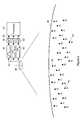
- FIG. 2is a block diagram of a communications system incorporating a plurality of the radios shown in FIG. 1, according to the invention.
- FIG. 3is a graph depicting a power spectrum for determining which radios are tuned to what frequency in accordance with the invention.
- FIG. 1shows a block diagram of a radio 10 , such as a vehicle radio, that incorporates a system for transmitting a unique carrier frequency signal depending on which radio station the radio 10 is currently tuned to.
- the radio 10includes an AM antenna 12 that collects and tunes AM (amplitude modulated) radio frequency signals, and sends the signals to an AM tuner 14 that filters and tunes a particular AM frequency bandwidth from an AM radio station. Additionally, the radio 10 includes an FM antenna 16 that collects and tunes FM (frequency modulated) radio frequency signals, and sends the signals to an FM tuner 18 that filters and tunes a particular FM frequency bandwidth from an FM radio station.
- AM antenna 12that collects and tunes AM (amplitude modulated) radio frequency signals, and sends the signals to an AM tuner 14 that filters and tunes a particular AM frequency bandwidth from an AM radio station.
- the radio 10includes an FM antenna 16 that collects and tunes FM (frequency modulated) radio frequency signals, and sends the signals to an FM tuner 18 that filters and tunes a particular
- the part of the radio 10 using the antennas 12 and 16 , the AM tuner 14 and the FM tuner 18are for conventional land-based radios, known in the art.
- the radio 10includes a satellite receive/transmit antenna 20 that receives satellite radio signals from a satellite (see FIG. 2 ), and sends the signals to a satellite tuner 22 that filters and tunes a particular frequency bandwidth from a satellite station.
- the satellite antenna 20 and the satellite tuner 22can be the type used in association with a DARS referred to above, in combination with the conventional land-based AM and FM radio.
- the antenna 20is also used to transmit a unique carrier frequency signal to the satellite based on which station the radio 10 is currently tuned to as will be described below.
- the tuners 14 , 18 and 22can be any type of suitable tuner for a particular heterodyne and/or satellite DARS known in the art.
- the radio 10includes a user interface 26 that allows the user of the radio 10 to select which station he desires to listen to for all of the available AM, FM and satellite stations. Depending on which station is selected, the interface 26 sends a selection signal to each of the tuners 14 , 18 and 22 , which causes the appropriate tuner that is selected to output a signal to an audio generation system 28 .
- the audio generation system 28takes the particular frequency or encoded signal from the selected tuner 14 , 18 or 22 , and generates an audio signal that is then applied to the radio speakers (not shown) for listening.
- the depiction of the tuners 14 , 16 and 22 , the user interface 26 , and the audio generation system 28is in a simplistic form for discussion purposes.
- the selection signal from the user interface 26is also applied to a carrier wave frequency determination system 30 , according to the invention. Based on which station the user selects by the user interface 26 , the carrier wave frequency system 30 will provide an output signal identifying that selection to a carrier wave generator 32 . The carrier wave generator 32 then generates a unique carrier wave frequency for that particular output from the system 30 . Each selected radio station that is being monitored has its own unique identification code in the frequency determination system 30 , and each identification code has its own unique carrier wave frequency that is generated by the carrier wave generator 32 . The carrier wave is applied to the antenna 20 where it is transmitted to the satellite. In one embodiment, each radio 10 tuned to the same station would transmit the same unique frequency signal at substantially the same power level. A frequency reference signal is applied from the satellite tuner 22 to the carrier wave generator 32 to align the carrier wave frequency with the receiver in the satellite so that various carrier wave frequencies identifying the individual stations can be more closely spaced, as would be understood to those skilled in the art.
- the radio 10will transmit a unique carrier wave frequency identifying the station.
- a transmitterradio 10
- n distinct frequencies f 1 -f nare defined in the available spectrum.
- the carriercan be transmitted periodically depending on the particular application to conserve resources.
- the carrier wave transmitted by the radio 10is received by a satellite in one embodiment.
- a satelliteto receive the state information from the radio 10 is by way of a non-limiting example, in that a ground-based receiver can also be used to receive the state information from the radio 10 . Since each radio 10 will transmit a carrier wave, the narrowness of the carrier wave spectrum required is only limited by the stability and accuracy of generation of the transmission frequency, and by the rate that each radio 10 changes between states. Thus, for a large number of radios 10 , the required band width for this scheme is negligible compared to the bandwidth necessary to support large numbers of individual communication links.
- the carrier wave generator 32will provide 20-30 different carrier wave frequencies, one for each of the stations being monitored.
- the carrier wave generator 32will generate frequency signals in the 2-3 GHz range, where each frequency signal has a bandwidth of about 1 kHz to separate the different carrier wave frequencies. If one of the radios 10 is turned off, it will stop sending the particular carrier wave, and thus the power contribution from that radio 10 will stop, and the overall transmitted power from all of the radios will decrease. Likewise, if the user selects a different radio station, the carrier wave transmitted by that radio will change, and the overall power for one frequency will decrease and the overall power for another frequency will increase.
- FIG. 2shows a diagram of a communications system 34 of the invention from the satellite perspective, according to the invention.
- a satellite 36 orbiting the Earth 38monitors a certain predefined reception area on the Earth 38 .
- a plurality of radio receiver locations 40are depicted on the Earth 38 , where each location 40 represents a radio 10 .
- Each location 40is designated with a frequency f 1 , f 2 , or f 3 as the carrier wave generated by the carrier wave generator 32 for that radio 10 . Only three frequencies are shown for discussion purposes. Of course, in a practical application, the satellite 36 will monitor many more than three different frequencies and many more locations 40 (possibly millions of locations) will be transmitting signals. The satellite 36 would also transmit the radio signals received by the antenna 20 and deciphered by the tuner 22 .
- the satellite 36receives the carrier wave frequencies f 1 -f 3 from the radio 10 . All of the carrier wave frequencies f 1 combine to give a certain power contribution for that frequency, all of the carrier wave frequencies f 2 combine to give a power contribution for that frequency, and all of the carrier wave frequencies f 3 combine to give a power output for that frequency. Since all of the radios 10 emit the carrier waves at substantially the same power level, each contribution to the total power from each radio 10 is about the same.
- the satellite 36includes a first frequency bin filter 42 that only passes the carrier wave signals at frequency f 1 , a second frequency bin filter 44 that only passes the carrier wave signals at frequency f 2 , and a third frequency bin filter 46 that only passes the carrier wave signals at frequencies f 3 .
- the filters 42 - 46can be any suitable narrow bandpass filter known to those skilled in the art that effectively passes the signals in the bandwidth of interest. In this depiction, many carrier waves arrive at each frequency bin filter 42 - 46 , and will be phase incoherent relative to each other. Therefore, a measurement of the total power in each frequency bin will be proportional to the number of transmitters transmitting in that frequency bin, and is thus a measure of the number of transmitters in the state associated with that frequency bin.
- the output from the filter 42is applied to a power detector 48
- the output of the filter 44is applied to a power detector 50
- the output of the filter 46is applied to a power detector 52 .
- the power detectors 48 - 52provide a measurement of the power received by the satellite 36 at the particular bandwidth passed by each of the filters 42 - 46 .
- the power detectors 48 - 52are square law power detectors, known to those skilled in the art. However, any kind of power detector suitable for digital or analog power detection of the type described herein can be used in accordance with the teachings of the present invention.
- the power detection signal from each of the power detectors 48 - 52is then applied to a processor 54 that converts the analog power signal to a digital signal, and provides an estimation of the number of transmissions for each frequency f 1 -f 3 .
- the estimation of the number of transmissions at each frequency f 1 -f 3is based on the expected receiver noise power and the expected received power of a single transmission from a radio 10 . In other words, because the noise of the receiver processing the frequency signal is known, and the power of each carrier frequency transmission from each radio 10 is known, the number of transmissions at each frequency f 1 -f 3 can be calculated.
- the expected receiver noise poweris subtracted from the measured power level at each frequency, and then divided by the expected received power from a single transmitter to give the number of transmissions at each frequency f 1 -f 3 .
- FIG. 3shows a graph of how the estimation of the number of the transmissions for each frequency is made according to one embodiment of the invention. Each of the frequencies f 1 , f 2 , and f 3 is depicted on the horizontal axis, and the power detected at each frequency is depicted on the vertical axis. Each separation of power is based on the receiver noise N 0 . If no radio 10 is transmitting a particular carrier wave frequency, then the total output power at that frequency would be N 0 .
- each power contribution from each radio 10 at a particular frequencyis known to be one-quarter of N 0 . Therefore, the total power output contribution for twelve radios transmitting at frequency f 1 is 4N 0 , the total power output for sixteen radios transmitting at frequency f 2 is 5N 0 , and the total power output for four radios transmitting at frequency f 3 is 2N 0 .
- the satellite 36can download the information concerning the number of radios tuned to a particular station to a ground based station (not shown) along with the normal telemetry information from the satellite 36 that gives the satellite's vital information.
- the transmit power required for each radio 10can be determined from the desired accuracy in counting the number of transmissions in each state. It is not necessary in the scheme of the invention to have sufficient power for a single transmitter to be detectable. This would have been have necessary if individual communications were employed. For example, consider a case where the uncertainty in the number of transmitters in a particular state can be as many as one hundred transmissions. The transmit power can then be set so that the received power from one radio 10 is roughly ⁇ fraction (1/100) ⁇ th of the noise power in the detector.
Landscapes
- Engineering & Computer Science (AREA)
- Signal Processing (AREA)
- Physics & Mathematics (AREA)
- Astronomy & Astrophysics (AREA)
- Aviation & Aerospace Engineering (AREA)
- General Physics & Mathematics (AREA)
- Computer Networks & Wireless Communication (AREA)
- Radio Relay Systems (AREA)
- Monitoring And Testing Of Transmission In General (AREA)
- Mobile Radio Communication Systems (AREA)
Abstract
Description
Claims (4)
Priority Applications (1)
| Application Number | Priority Date | Filing Date | Title |
|---|---|---|---|
| US09/662,047US6424816B1 (en) | 1998-06-10 | 2000-09-15 | Statistical communication link |
Applications Claiming Priority (2)
| Application Number | Priority Date | Filing Date | Title |
|---|---|---|---|
| US09/095,215US6219524B1 (en) | 1998-06-10 | 1998-06-10 | Statistical communication link |
| US09/662,047US6424816B1 (en) | 1998-06-10 | 2000-09-15 | Statistical communication link |
Related Parent Applications (1)
| Application Number | Title | Priority Date | Filing Date |
|---|---|---|---|
| US09/095,215DivisionUS6219524B1 (en) | 1998-06-10 | 1998-06-10 | Statistical communication link |
Publications (1)
| Publication Number | Publication Date |
|---|---|
| US6424816B1true US6424816B1 (en) | 2002-07-23 |
Family
ID=22250706
Family Applications (2)
| Application Number | Title | Priority Date | Filing Date |
|---|---|---|---|
| US09/095,215Expired - LifetimeUS6219524B1 (en) | 1998-06-10 | 1998-06-10 | Statistical communication link |
| US09/662,047Expired - LifetimeUS6424816B1 (en) | 1998-06-10 | 2000-09-15 | Statistical communication link |
Family Applications Before (1)
| Application Number | Title | Priority Date | Filing Date |
|---|---|---|---|
| US09/095,215Expired - LifetimeUS6219524B1 (en) | 1998-06-10 | 1998-06-10 | Statistical communication link |
Country Status (1)
| Country | Link |
|---|---|
| US (2) | US6219524B1 (en) |
Cited By (9)
| Publication number | Priority date | Publication date | Assignee | Title |
|---|---|---|---|---|
| US20030067898A1 (en)* | 2001-10-04 | 2003-04-10 | Raghu Challa | Method and apparatus for acquiring pilots over code space and frequency errors in a CDMA communication system |
| US20040127192A1 (en)* | 2001-03-19 | 2004-07-01 | Ceresoli Carl D. | System and method for obtaining comprehensive vehicle radio listener statistics |
| US20040210922A1 (en)* | 2002-01-08 | 2004-10-21 | Peiffer John C. | Method and apparatus for identifying a digital audio dignal |
| US20050195777A1 (en)* | 2004-03-03 | 2005-09-08 | Atheros Communications, Inc. | Implementing location awareness in WLAN devices |
| US7020217B1 (en)* | 1999-11-04 | 2006-03-28 | Xm Satellite Radio, Inc. | Satellite digital audio radio receiver with instant replay capability |
| US20060148514A1 (en)* | 2003-06-26 | 2006-07-06 | David Reagor | Through-the-earth radio |
| US20090067398A1 (en)* | 2004-03-03 | 2009-03-12 | Green Michael R | Implementing Location Awareness In WLAN Devices |
| US20090122204A1 (en)* | 2005-06-07 | 2009-05-14 | Janne Aaltonen | Receiving devices |
| US20150326330A1 (en)* | 2014-05-07 | 2015-11-12 | GM Global Technology Operations LLC | Am/fm antenna performance in the presence of wide-band noise using tunable high-q structures |
Families Citing this family (3)
| Publication number | Priority date | Publication date | Assignee | Title |
|---|---|---|---|---|
| US6947703B2 (en)* | 2002-05-20 | 2005-09-20 | Ceresoli Carl D | System for determining satellite radio listener statistics |
| IL159904A0 (en)* | 2004-01-16 | 2004-06-20 | Future Wireless Ltd | Method and apparatus for determining the efficiency of radio publicity and/or broadcasted programs |
| US20100131642A1 (en)* | 2007-04-17 | 2010-05-27 | Metrometrix Pty Ltd. | System for monitoring the use of content in a vehicle |
Citations (2)
| Publication number | Priority date | Publication date | Assignee | Title |
|---|---|---|---|---|
| US5278988A (en)* | 1991-06-14 | 1994-01-11 | A. C. Nielsen Company | Automated receiver monitoring method and apparatus |
| US5896554A (en)* | 1996-12-02 | 1999-04-20 | K.K. Video Research | Status monitoring apparatus for car radio |
Family Cites Families (1)
| Publication number | Priority date | Publication date | Assignee | Title |
|---|---|---|---|---|
| WO1996024991A1 (en)* | 1995-02-08 | 1996-08-15 | Actual Radio Measurement | Remote listenership monitoring system |
- 1998
- 1998-06-10USUS09/095,215patent/US6219524B1/ennot_activeExpired - Lifetime
- 2000
- 2000-09-15USUS09/662,047patent/US6424816B1/ennot_activeExpired - Lifetime
Patent Citations (2)
| Publication number | Priority date | Publication date | Assignee | Title |
|---|---|---|---|---|
| US5278988A (en)* | 1991-06-14 | 1994-01-11 | A. C. Nielsen Company | Automated receiver monitoring method and apparatus |
| US5896554A (en)* | 1996-12-02 | 1999-04-20 | K.K. Video Research | Status monitoring apparatus for car radio |
Cited By (22)
| Publication number | Priority date | Publication date | Assignee | Title |
|---|---|---|---|---|
| US7020217B1 (en)* | 1999-11-04 | 2006-03-28 | Xm Satellite Radio, Inc. | Satellite digital audio radio receiver with instant replay capability |
| US20040127192A1 (en)* | 2001-03-19 | 2004-07-01 | Ceresoli Carl D. | System and method for obtaining comprehensive vehicle radio listener statistics |
| US6934508B2 (en)* | 2001-03-19 | 2005-08-23 | Navigaug Inc. | System and method for obtaining comprehensive vehicle radio listener statistics |
| US7359687B2 (en)* | 2001-03-19 | 2008-04-15 | Navigauge, Inc. | System and method for obtaining comprehensive vehicle radio listener statistics |
| US20050221774A1 (en)* | 2001-03-19 | 2005-10-06 | Ceresoli Carl D | System and method for obtaining comprehensive vehicle radio listener statistics |
| US20030067898A1 (en)* | 2001-10-04 | 2003-04-10 | Raghu Challa | Method and apparatus for acquiring pilots over code space and frequency errors in a CDMA communication system |
| US7020180B2 (en)* | 2001-10-04 | 2006-03-28 | Qualcomm Inc. | Method and apparatus for acquiring pilots over code space and frequency errors in a CDMA communication system |
| US7742737B2 (en)* | 2002-01-08 | 2010-06-22 | The Nielsen Company (Us), Llc. | Methods and apparatus for identifying a digital audio signal |
| US20040210922A1 (en)* | 2002-01-08 | 2004-10-21 | Peiffer John C. | Method and apparatus for identifying a digital audio dignal |
| US8548373B2 (en) | 2002-01-08 | 2013-10-01 | The Nielsen Company (Us), Llc | Methods and apparatus for identifying a digital audio signal |
| US7149472B2 (en)* | 2003-06-26 | 2006-12-12 | Los Alamos National Security, Llc | Through-the-earth radio |
| US20060148514A1 (en)* | 2003-06-26 | 2006-07-06 | David Reagor | Through-the-earth radio |
| US8036153B2 (en) | 2004-03-03 | 2011-10-11 | Qualcomm Atheros, Inc. | Implementing location awareness in WLAN devices |
| US20090067398A1 (en)* | 2004-03-03 | 2009-03-12 | Green Michael R | Implementing Location Awareness In WLAN Devices |
| US20080130545A1 (en)* | 2004-03-03 | 2008-06-05 | Green Michael R | Implementing Location Awareness In WLAN Devices |
| US20050195777A1 (en)* | 2004-03-03 | 2005-09-08 | Atheros Communications, Inc. | Implementing location awareness in WLAN devices |
| US8155018B2 (en) | 2004-03-03 | 2012-04-10 | Qualcomm Atheros, Inc. | Implementing location awareness in WLAN devices |
| US7352733B2 (en)* | 2004-03-03 | 2008-04-01 | Atheros Communications, Inc. | Implementing location awareness in WLAN devices |
| US20090122204A1 (en)* | 2005-06-07 | 2009-05-14 | Janne Aaltonen | Receiving devices |
| US7970369B2 (en)* | 2005-06-07 | 2011-06-28 | Nokia Corporation | Receiving devices |
| US20150326330A1 (en)* | 2014-05-07 | 2015-11-12 | GM Global Technology Operations LLC | Am/fm antenna performance in the presence of wide-band noise using tunable high-q structures |
| US9515753B2 (en)* | 2014-05-07 | 2016-12-06 | GM Global Technology Operations LLC | AM/FM antenna performance in the presence of wide-band noise using tunable high-Q structures |
Also Published As
| Publication number | Publication date |
|---|---|
| US6219524B1 (en) | 2001-04-17 |
Similar Documents
| Publication | Publication Date | Title |
|---|---|---|
| US6424816B1 (en) | Statistical communication link | |
| US5345245A (en) | Differential data signal transmission technique | |
| US7373152B2 (en) | Radio signal strength mapping through a telematics system | |
| US6983123B2 (en) | Apparatus and method for reusing satellite broadcast spectrum for terrestrially broadcast signals | |
| US6600730B1 (en) | System for distribution of satellite signals from separate multiple satellites on a single cable line | |
| US5303393A (en) | Integrated radio satellite response system and method | |
| EP1098390B1 (en) | Satellite communication array transceiver | |
| US5036523A (en) | Automatic frequency control of satellite transmitted spread spectrum signals | |
| WO1998053562A1 (en) | Method of and system for providing geographically targeted broadcast satellite service | |
| US20090189806A1 (en) | System for transmitting a signal for positioning and method for producing the system | |
| CA2738268A1 (en) | Distributed distance measurement system for locating a geostationary satellite | |
| US7327989B2 (en) | Dual channel two-way satellite communication | |
| US5862235A (en) | Multiple broadcast channel transmitter arrangment | |
| EP1044523B1 (en) | Apparatus and method for reusing satellite broadcast spectrum for terrestrially broadcast signals | |
| US6643509B1 (en) | Civil aviation communication system | |
| US20050079876A1 (en) | Method of location using signals of unknown origin | |
| Bergadà et al. | Polarization diversity in a long-haul transequatorial HF link from Antarctica to Spain | |
| JP3236160B2 (en) | Satellite broadcast reception information processing device | |
| US8032100B2 (en) | System and method of communicating multiple carrier waves | |
| Henry et al. | Radio Frequency Interference Experiment Design for the Applications Technology Satellite | |
| US8593984B2 (en) | Apparatus and method for measuring individual receiving power using identification signal | |
| BROADCAST et al. | Research and Development Report | |
| Jamshidi et al. | Intelnet Services—A global data distribution and collection scheme | |
| CN1096910A (en) | Adopt the radio frequency broadcasting systems and the method for two low-cost geosynchronous satellites | |
| Swartwout | Interference potential of personal radio services |
Legal Events
| Date | Code | Title | Description |
|---|---|---|---|
| STCF | Information on status: patent grant | Free format text:PATENTED CASE | |
| AS | Assignment | Owner name:NORTHROP GRUMMAN CORPORATION, CALIFORNIA Free format text:ASSIGNMENT OF ASSIGNORS INTEREST;ASSIGNOR:TRW, INC. N/K/A NORTHROP GRUMMAN SPACE AND MISSION SYSTEMS CORPORATION, AN OHIO CORPORATION;REEL/FRAME:013751/0849 Effective date:20030122 Owner name:NORTHROP GRUMMAN CORPORATION,CALIFORNIA Free format text:ASSIGNMENT OF ASSIGNORS INTEREST;ASSIGNOR:TRW, INC. N/K/A NORTHROP GRUMMAN SPACE AND MISSION SYSTEMS CORPORATION, AN OHIO CORPORATION;REEL/FRAME:013751/0849 Effective date:20030122 | |
| FPAY | Fee payment | Year of fee payment:4 | |
| FEPP | Fee payment procedure | Free format text:PAYOR NUMBER ASSIGNED (ORIGINAL EVENT CODE: ASPN); ENTITY STATUS OF PATENT OWNER: LARGE ENTITY | |
| AS | Assignment | Owner name:NORTHROP GRUMMAN SPACE & MISSION SYSTEMS CORP.,CAL Free format text:ASSIGNMENT OF ASSIGNORS INTEREST;ASSIGNOR:NORTHROP GRUMMAN CORPORTION;REEL/FRAME:023699/0551 Effective date:20091125 Owner name:NORTHROP GRUMMAN SPACE & MISSION SYSTEMS CORP., CA Free format text:ASSIGNMENT OF ASSIGNORS INTEREST;ASSIGNOR:NORTHROP GRUMMAN CORPORTION;REEL/FRAME:023699/0551 Effective date:20091125 | |
| FPAY | Fee payment | Year of fee payment:8 | |
| AS | Assignment | Owner name:NORTHROP GRUMMAN SYSTEMS CORPORATION,CALIFORNIA Free format text:ASSIGNMENT OF ASSIGNORS INTEREST;ASSIGNOR:NORTHROP GRUMMAN SPACE & MISSION SYSTEMS CORP.;REEL/FRAME:023915/0446 Effective date:20091210 Owner name:NORTHROP GRUMMAN SYSTEMS CORPORATION, CALIFORNIA Free format text:ASSIGNMENT OF ASSIGNORS INTEREST;ASSIGNOR:NORTHROP GRUMMAN SPACE & MISSION SYSTEMS CORP.;REEL/FRAME:023915/0446 Effective date:20091210 | |
| FPAY | Fee payment | Year of fee payment:12 |