US6424674B1 - Multi-tone transciever for multiple users - Google Patents
Multi-tone transciever for multiple usersDownload PDFInfo
- Publication number
- US6424674B1 US6424674B1US09/236,122US23612299AUS6424674B1US 6424674 B1US6424674 B1US 6424674B1US 23612299 AUS23612299 AUS 23612299AUS 6424674 B1US6424674 B1US 6424674B1
- Authority
- US
- United States
- Prior art keywords
- symbol
- control signal
- dmt
- user
- request
- Prior art date
- Legal status (The legal status is an assumption and is not a legal conclusion. Google has not performed a legal analysis and makes no representation as to the accuracy of the status listed.)
- Expired - Lifetime
Links
Images


Classifications
- H—ELECTRICITY
- H04—ELECTRIC COMMUNICATION TECHNIQUE
- H04L—TRANSMISSION OF DIGITAL INFORMATION, e.g. TELEGRAPHIC COMMUNICATION
- H04L5/00—Arrangements affording multiple use of the transmission path
- H04L5/02—Channels characterised by the type of signal
- H04L5/023—Multiplexing of multicarrier modulation signals, e.g. multi-user orthogonal frequency division multiple access [OFDMA]
Definitions
- This inventionrelates generally to telecommunications, and, more particularly, to a multi-tone transceiver for multiple users.
- a line cardIn communications systems, particularly telephony, it is common practice to transmit signals between a subscriber station and a central switching office via a two-wire bi-directional communication channel.
- a line cardgenerally connects the subscriber station to the central switching office.
- the primary functions of the line cardrange from supplying talk battery to performing impedance matching to handling ringing signal, voice and data signals, and testing signals.
- POTSPlain Old Telephone System
- a recent trendhas been to utilize line cards to support protocols for transmission of digital data.
- the Plain Old Telephone Systemdesigned primarily for voice communication, provides an inadequate data transmission rate for many modem applications.
- designerssought innovative and cost-effective solutions that would take advantage of the existing network infrastructure.
- Several technological advancementswere proposed in the telecommunications industry that made use of the existing network of telephone wires. The most promising of these technologies is the xDSL technology.
- DSLis making the existing network of telephone lines more robust and versatile. Once considered virtually unusable for broadband communications, an ordinary twisted pair equipped with DSL interfaces can transmit videos, television, and very high-speed data. The fact that more than six hundred million telephone lines exist around the world is a compelling reason that these lines will serve as the primary transmission conduits for at least several more decades. Because DSL utilizes telephone wiring already installed in virtually every home and business in the world, it has been embraced by many as one of the more promising and viable options.
- DSL technologiesleave Plain Old Telephone Service undisturbed.
- Traditional analog voice band interfacesuse the same frequency band, 300 Hertz (Hz)-4 Kilohertz (KHz), as telephone service, thereby preventing concurrent voice and data use.
- a DSL interfaceoperates at frequencies above the voice channels from about 30 KHz to 1.1 Megahertz (MHz).
- a single DSL lineis capable of offering simultaneous channels for voice and data.
- DSL systemsuse digital signal processing (DSP) to increase throughput and signal quality through common copper telephone wire. It provides a downstream data transfer rate from the DSL Point-of-Presence (POP) to the subscriber location at speeds of up to 6 Mega-bits per second (MBPS). Even a more modest transfer rate of 1.5 MBPS, for instance, is fifty times faster than a conventional 28.8 kilobits per second (KBPS).
- DSPdigital signal processing
- ADSLAsymmetrical Digital Subscriber Line
- the ADSL standardis described in ANSI T1.413 Issue 2, entitled, “Interface Between Networks and Customer Installation—Asymmetric Digital Subscriber Line (ADSL) Metallic Interface, Rev. R6, dated Sep. 26, 1997, incorporated herein by reference in its entirety.
- ADSL modemsuse two competing modulation schemes: discrete multi-tone (DMT) and carrierless amplitude/phase modulation (CAP).
- DMTdiscrete multi-tone
- CAPcarrierless amplitude/phase modulation
- the technology employed by DMT ADSL modemsis termed discrete multi-tone.
- the standarddefines 256 discrete tones.
- Each tonerepresents a carrier signal that can be modulated with a digital signal for transmitting data.
- the specific frequency for a given toneis 4.3125 KHz times the tone number.
- Tones 1 - 7are reserved for voice band and guard band (i.e., tone 1 is the voice band and tones 2 - 7 are guard bands).
- the guard bandhelps isolate the voice band from the ADSL data bands.
- a splittermay be used to isolate any voice band signal from the data tones.
- Tones 8 - 32are used to transmit data upstream (i.e., from the user), and tones 33 - 256 are used to transmit data downstream (i.e., to the user). Alternatively, all the data tones 8 - 256 may be used for downstream data, and upstream data present on tones 8 - 32 would be detected using echo cancellation. Because more tones are used for downstream communication than for upstream communication, the transfer is said to be asymmetric.
- the modems on both sides of the connectionsense and analyze which tones are less affected by impairments in the telephone line. Each tone that is accepted is used to carry information. Accordingly, the maximum capacity is set by the quality of the telephone connection.
- the maximum data rate defined by the ADSL specification, assuming all tones are used,is about 8 MBPS downstream and about 640 KBPS upstream.
- a typical point-to-point ADSL connectionuses an ADSL transceiver at the central office (CO) connected to another ADSL transceiver via a subscriber line.
- COcentral office
- a plurality of transceiversis located on a line card.
- the number of transceivers that can be placed on one line cardis limited because of space constraints and power dissipation concerns.
- the ADSL serviceis available to a relatively small fraction of all potential users.
- the processors of the ADSL transceiversare not always efficiently utilized, particularly between downloads, where the ADSL processors are essentially idling.
- the inefficient use of the ADSL processorslimits the number of users that can have access to a multi-tone transceiver at any given time.
- the present inventionis directed to overcoming, or at least reducing the effects of, one or more of the problems set forth above.
- a methodfor supporting a plurality of user transceivers with a host transceiver.
- the methodincludes allocating at least one symbol of a DMT frame to a first user transceiver of the plurality of transceivers, providing a control signal from a second user transceiver of the plurality of transceivers to the host transceiver, allocating at least one symbol of the DMT frame to the second user transceiver in response to the control signal.
- an apparatusin one aspect of the present invention, includes a transmit block capable of transmitting data within a first portion of a DMT frame to a first user transceiver over a first connection.
- the apparatusincludes a control block adapted to receive a control signal over a second connection, the control block capable of allocating a second portion of the DMT frame to a second user transceiver for data transmission in response to the control signal.
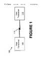
- FIG. 1illustrates a stylized block diagram of a communications system in accordance with the present invention
- FIG. 2depicts a stylized block diagram of a specific embodiment of the communications system of FIG. 1 in accordance with the present invention
- FIG. 3illustrates a stylized block diagram of a host modem of the communications system of FIG. 2 in accordance with the present invention
- FIG. 4depicts a standard DMT frame utilized for data communications between the host and user modems of FIG. 3;
- FIG. 5illustrates an allocation of symbols of the DMT frame of FIG. 4 in accordance with the present invention
- FIG. 6illustrates an alternative allocation of symbols of the DMT frame of FIG. 4 in accordance with the present invention when all symbols are utilized.
- FIGS. 7 a and 7 billustrate an example of an allocation of symbols of the DMT frame in accordance with the present invention when some symbols are unused.
- the communications system 100includes a host transceiver 105 and a user transceiver 110 capable of communicating with each other over a connection 115 .
- the connection 115may be either a wire-line connection or a wire-less connection, depending on the application.
- the host and user transceiver 105 , 110communicate with each other using a common communications protocol (i.e. a communications standard such ADSL, ISDN, DECT, TCP/IP etc.) that defines the transmission parameters such as the format of data to be transmitted, error checking algorithm, retransmission scheme, and the like.
- the host and user transceivers 105 , 110may be a pair of modems, fax machines, cellular phones, or any other devices capable of communicating with each other.
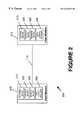
- FIG. 2illustrates one embodiment of a communications system 200 in accordance with the present invention.
- FIG. 2illustrates a host transceiver 105 that supports one or more of the user transceivers 110 over one or more of the connections 115 .
- the host transceiveris an ADSL (host) modem 205
- the user transceivers 110are ADSL (user) modems 210 (a-n)
- the connections 115are telephone lines 215 (a-n).
- the host modem 205may be located in a central office of a telephone service provider
- the user modems 210 (a-n)may be located in customer premises (CP), which could include homes, businesses, or the like.
- CPcustomer premises
- the host modem 205will couple the user modems 210 (a-n) to another service provider through the central office. For example, if an individual at one of the customer premises desires Internet service, then a connection is usually made between one of the user modems 210 (a-n) and an Internet Service Provider (ISP) via the host modem 205 at the central office.
- ISPInternet Service Provider
- the host and user modems 205 , 210 (a-n)are DMT ADSL modems, wherein the host modem 205 generates the tones necessary for compatibility with the user modems 210 (a-n).
- the host and user modems 205 , 210 (a-n)communicate with each other using a certain number of these tones for data transmission.
- the host and user modems 205 , 210 (a-n)have the capability of transmitting on all of the 256 allocated tones, they usually use only a portion of these tones for typical data transmissions.
- the capacity offered by the ADSL DMT modems 205 , 210 (a-n)generally depends on the quality (i.e., the clarity) of the communication channel and that all 256 tones are usable by the modems 205 , 210 (a-n).
- Each user modem 210 (a-n)comprises a control block 220 (a-n), transmit block 230 (a-n), and receive block 240 (a-n).
- the control block 220 (a-n)is capable of transmitting and receiving control signals to and from the host modem 205 .
- the control signalsmay include information such the transmission rate, the priority scheme (i.e., class of ADSL service), and the like.
- the transmit block 230 (a-n) and the receive block 240 (a-n)are capable of respectively transmitting and receiving data to and from the host modem 205 over a portion of a DMT frame.
- the portion of the DMT frame utilized for transmitting and receiving datais identified by the control block 220 (a-n). It is contemplated that the transmit block 230 (a-n) and receive block 240 (a-n) can be implemented in a variety of ways by those skilled in the art having the benefit of this disclosure. Accordingly, the transmit and receive blocks 230 (a-n), 240 (a-n) will not be described in detail herein.
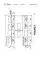
- FIG. 3a simplified block diagram of the host modem 205 is provided in accordance with the present invention.
- FIG. 3a simplified block diagram of the host modem 205 is provided in accordance with the present invention.
- FIG. 3a simplified block diagram of the host modem 205 is provided in accordance with the present invention.
- FIG. 3a simplified block diagram of the host modem 205 is provided in accordance with the present invention.
- FIG. 3a simplified block diagram of the host modem 205 is provided in accordance with the present invention.
- FIG. 3a simplified block diagram of the host modem 205 is provided in accordance with the present invention.
- the host modem 205includes transmit and receive functional blocks 305 , 310 , as well as a control block 315 to control their functions.
- the control blockallows the host modem 205 to support one or more of the user modems 210 (a-n) in accordance with the present invention.
- the transmit block 305includes a formatting and interfacing circuit 320 adapted to receive outgoing digital data over a data-out line 325 .
- the formatting and interfacing circuit 320performs functions such as cyclic redundancy checking (CRC), scrambling, forward error correction, and interleaving. As stated above, these functions are known to those of ordinary skill in the art, and are fully disclosed in the ANSI T1.413 Issue 2 standard.
- the transmit block 305also includes a modulator 330 .
- the modulator 330receives data from the formatting and interfacing circuit 320 , performs tone ordering, constellation encoding, and gain scaling functions in accordance with the number of available tones, and modulates the tone carriers with the transmitted data.
- a second data formatting and interfacing circuit 335within the transmit block 305 , inserts a cyclic prefix to the output of the modulator 330 .
- the formatting and interfacing circuit 335also buffers the output samples.
- the digital to analog (D/A) converter and filter 340converts the digital output samples from the formatting and interfacing circuit 335 to an analog waveform suitable for transmission over a phone connection 345 .
- the phone connection 345couples between the user and most modems 105 , 110 .
- the receive block 310includes an analog-to-digital (A/D) converter and filter 350 that receives an analog waveform over the phone connection 345 and samples the analog waveform to generate a digital signal.
- a formatting and interfacing circuit 355performs the functions known in the art such as frame alignment and time domain equalization. In time domain equalization, because the tones are at different frequencies, certain frequencies travel faster than others. As such, all the tones do not arrive at the same time. The time domain equalization function of the formatting and interfacing circuit 355 delays the faster tones to compensate for the propagation speed differences.
- the formatting and interfacing circuit 335also performs gain control to increase the amplitude of the received signal.
- a demodulator 360receives digital signal data from the formatting and interfacing circuit 355 and converts the time domain data from the formatting and interfacing circuit 365 to frequency domain data to recover the tones.
- the demodulator 360performs a slicing function to determine constellation points from the constellation encoded data, a demapping function to map the identified constellation point back to bits, and a decoding function (e.g., Viterbi decoding, if trellis constellation coding is employed).
- the demodulator 360also performs tone deordering to reassemble the serial bytes that were divided among the available tones.
- a second formatting and interfacing circuit 365 in the receive block 310performs forward error correction, CRC checking, and descrambling functions on the data received from the demodulator 360 .
- the reconstructed data provided by the formatting and interfacing circuit 365represents the sequential binary data that was sent by the “interfacing” modem 105 , 110 .
- the reconstructed datais provided to a data-in line 370
- the host modem 205utilizes time-division multiplexing, a process well known in the art, to support more than one user modem 210 (a-n).
- FIG. 4illustrates a typical ADSL TDM frame 400 , which comprises a plurality of symbols 410 (a-n), that is utilized for data communications between the host modem 205 and the user modem 210 (a-n).
- symbol410 (a-n) herein refers to a set of time domain samples produced by the modulator 330 .
- a new symbol 410 (a-n)is output every 250 ⁇ s (at a rate of 4000 per second).
- a symbol 410 (a-n)carries a total bit load equal to the sum of the numbers of bits used to modulate each carrier.
- a symbol 410 (a-n)is a supposition of all the modulated carriers.
- the host modem 205allocates a selected number of symbols 410 (a-n) of the TDM frame 400 to each user modem 210 (a-n) seeking a connection to the host modem 205 .
- symbols 410 (a-n) of the TDM frame 400For illustrative purposes, it is assumed that four user modems 210 (a-d) seek a connection to the host modem 205 .
- FIG. 5illustrates one example of allocating the symbols 410 (a-n) of the DMT frame 400 for servicing four user modems 210 (a-d).
- the letters “A” through “D,” as utilized herein,represent the symbol 410 (a-n) of the DMT frame 400 that is allocated to the four user modems 210 (a-b).
- the symbol 410 a identified by an “A”is allocated to the first user modem 210 a
- the symbol 410 a identified by an “B”is allocated to the second user modem 210 b
- the instant embodimentillustrates four users, it is contemplated that additional or fewer user modems 210 (a-n) can be supported by allocating the available symbols 410 (a-n) of the DMT frame 400 amongst the user modems 210 (a-n) seeking to connect to the host modem 205 .
- FIG. 5illustrates an alternative arrangement where the first user modem 210 a has a 50 percent higher symbol rate than the second user modem 210 b .
- the symbol rate allocated to each user modem 210 (a-d)may be determined according to a priority scheme.
- the control block 315 of the host modem 205determines how many symbols 410 (a-n) to allocate per user modem 210 (a-d) in a situation where multiple user modems 210 (a-d) seek to be serviced by the host modem 205 .
- the allocation of symbols 410 (a-n) to a particular user modem 210 (a-d)can be a dynamic process, as described in more detail below.
- the transmit block 230 (a-d)see FIG.
- the receive block 240 (a-d) of the user modem 210 (a-d)are capable of communicating with the host modem 205 over the allocated symbol 410 (a-n), or symbols 410 (a-n), if more than one is allocated per frame 400 .
- the first scenariois exemplified in FIGS. 7 a and 7 b .
- the first scenarioas seen in FIG. 7 a , there exists at least one unused symbol ( 410 b , 410 d , etc.) that may be allocated to the user modem 210 (a-d) that is requesting a high data rate.
- the unused symbols ( 410 b , 410 d , etc.)may exist because the other users may be operating at low rates.
- the control block 315 of the host modem 205simply assigns the unused symbols ( 410 b , 410 d , etc.) to the requesting user modem 210 (a-d), as seen in FIG. 7 b , where at least one of the unused symbols ( 410 b , 410 d , etc.) is allocated to the first user modem 410 a .
- the control block 315cannot allocate additional symbols 410 (a-n) in response to a request for higher symbol rate.
- the control block 315 of the host modem 205must reduce the data rate of an existing user modem 210 (a-d), which, in one embodiment, may be accomplished based on a priority scheme. For example, some users may desire a cheaper ADSL service, which may result in lower “average” data rates during peak times. On the other hand, some users may desire a more expensive ADSL service that provides a larger “average” data rate, even during peak times.
- At least one fixed symbol (e.g., a designated symbol) 410 (a-n) within the DMT frame 400may be reserved for transmitting control signals to and from the host modem 205 .
- the control block 220 (a-d) of the user modem 210 (a-d) requesting ADSL service from the host modem 205may monitor the designated symbol 410 (a-n).
- the designated symbol 410 (a-n), if not in use,may be utilized by the control block 220 (a-d) of the user modem 410 (a-d) for transmitting and/or receiving control signals to and from the host modem 205 .
- the control signalsmay include information such the transmission rate, the priority scheme (i.e., class of ADSL service), and the like.
- the host modem 205may transmit additional control signals to the user modems 210 (a-d), wherein the control signals specify the DMT symbol allocation for actual data transmission.
Landscapes
- Engineering & Computer Science (AREA)
- Signal Processing (AREA)
- Computer Networks & Wireless Communication (AREA)
- Telephonic Communication Services (AREA)
Abstract
Description
Claims (36)
Priority Applications (1)
| Application Number | Priority Date | Filing Date | Title |
|---|---|---|---|
| US09/236,122US6424674B1 (en) | 1999-01-22 | 1999-01-22 | Multi-tone transciever for multiple users |
Applications Claiming Priority (1)
| Application Number | Priority Date | Filing Date | Title |
|---|---|---|---|
| US09/236,122US6424674B1 (en) | 1999-01-22 | 1999-01-22 | Multi-tone transciever for multiple users |
Publications (1)
| Publication Number | Publication Date |
|---|---|
| US6424674B1true US6424674B1 (en) | 2002-07-23 |
Family
ID=22888215
Family Applications (1)
| Application Number | Title | Priority Date | Filing Date |
|---|---|---|---|
| US09/236,122Expired - LifetimeUS6424674B1 (en) | 1999-01-22 | 1999-01-22 | Multi-tone transciever for multiple users |
Country Status (1)
| Country | Link |
|---|---|
| US (1) | US6424674B1 (en) |
Cited By (6)
| Publication number | Priority date | Publication date | Assignee | Title |
|---|---|---|---|---|
| US20010021219A1 (en)* | 2000-03-07 | 2001-09-13 | Fujitsu Limited | xDSL transceiver |
| US20020136283A1 (en)* | 2001-03-21 | 2002-09-26 | International Business Machines Corporation | System and method for controlling line driver power in a shared digital subscriber line modem |
| US7277517B1 (en) | 2002-11-15 | 2007-10-02 | 3Com Corporation | Method for achieving symbol alignment to a pre-existing ADSL data exchange |
| US20070237178A1 (en)* | 2001-06-20 | 2007-10-11 | Juniper Networks, Inc. | Band control system for a digital subscriber network and band control method transfer |
| US9264533B2 (en) | 2000-01-07 | 2016-02-16 | Tq Delta, Llc | Systems and methods for establishing a diagnostic transmission mode and communicating over the same |
| US9893921B2 (en) | 2000-04-18 | 2018-02-13 | Tq Delta, Llc | Systems and methods for a multicarrier modulation system with a variable margin |
Citations (6)
| Publication number | Priority date | Publication date | Assignee | Title |
|---|---|---|---|---|
| US5521906A (en)* | 1995-01-26 | 1996-05-28 | Motorola Inc. | Method and apparatus for updating carrier channel allocations |
| WO1998010546A2 (en)* | 1996-09-02 | 1998-03-12 | Telia Ab (Publ) | Improvements in, or relating to, multi-carrier transmission systems |
| US5742640A (en)* | 1995-03-07 | 1998-04-21 | Diva Communications, Inc. | Method and apparatus to improve PSTN access to wireless subscribers using a low bit rate system |
| US5742639A (en)* | 1994-05-13 | 1998-04-21 | Westinghouse Electric Corporation | Mobile terminal apparatus and method for a satellite communication system |
| US5838667A (en)* | 1995-07-11 | 1998-11-17 | Amati Communications Corporation | Time division duplexed high speed data transmission system and method |
| US6144696A (en)* | 1997-12-31 | 2000-11-07 | At&T Corp. | Spread spectrum bit allocation algorithm |
- 1999
- 1999-01-22USUS09/236,122patent/US6424674B1/ennot_activeExpired - Lifetime
Patent Citations (6)
| Publication number | Priority date | Publication date | Assignee | Title |
|---|---|---|---|---|
| US5742639A (en)* | 1994-05-13 | 1998-04-21 | Westinghouse Electric Corporation | Mobile terminal apparatus and method for a satellite communication system |
| US5521906A (en)* | 1995-01-26 | 1996-05-28 | Motorola Inc. | Method and apparatus for updating carrier channel allocations |
| US5742640A (en)* | 1995-03-07 | 1998-04-21 | Diva Communications, Inc. | Method and apparatus to improve PSTN access to wireless subscribers using a low bit rate system |
| US5838667A (en)* | 1995-07-11 | 1998-11-17 | Amati Communications Corporation | Time division duplexed high speed data transmission system and method |
| WO1998010546A2 (en)* | 1996-09-02 | 1998-03-12 | Telia Ab (Publ) | Improvements in, or relating to, multi-carrier transmission systems |
| US6144696A (en)* | 1997-12-31 | 2000-11-07 | At&T Corp. | Spread spectrum bit allocation algorithm |
Cited By (20)
| Publication number | Priority date | Publication date | Assignee | Title |
|---|---|---|---|---|
| US9479637B2 (en) | 2000-01-07 | 2016-10-25 | Tq Delta, Llc | Systems and methods for establishing a diagnostic transmission mode and communicating over the same |
| US9319512B2 (en) | 2000-01-07 | 2016-04-19 | Tq Delta, Llc | Systems and methods for establishing a diagnostic transmission mode and communicating over the same |
| US9264533B2 (en) | 2000-01-07 | 2016-02-16 | Tq Delta, Llc | Systems and methods for establishing a diagnostic transmission mode and communicating over the same |
| US9838531B2 (en) | 2000-01-07 | 2017-12-05 | Tq Delta, Llc | Systems and methods for establishing a diagnostic transmission mode and communicating over the same |
| US10623559B2 (en) | 2000-01-07 | 2020-04-14 | Tq Delta, Llc | Systems and methods for establishing a diagnostic transmission mode and communicating over the same |
| US10264119B2 (en) | 2000-01-07 | 2019-04-16 | Tq Delta, Llc | Systems and methods for establishing a diagnostic transmission mode and communicating over the same |
| US9973624B2 (en) | 2000-01-07 | 2018-05-15 | Tq Delta, Llc | Systems and methods for establishing a diagnostic transmission mode and communicating over the same |
| US6845125B2 (en)* | 2000-03-07 | 2005-01-18 | Fujitsu Limited | xDSL transceiver |
| US20010021219A1 (en)* | 2000-03-07 | 2001-09-13 | Fujitsu Limited | xDSL transceiver |
| US9893921B2 (en) | 2000-04-18 | 2018-02-13 | Tq Delta, Llc | Systems and methods for a multicarrier modulation system with a variable margin |
| US10708104B2 (en) | 2000-04-18 | 2020-07-07 | Tq Delta, Llc | Systems and methods for a multicarrier modulation system with a variable margin |
| US6965637B2 (en)* | 2001-03-21 | 2005-11-15 | International Business Machines Corporation | System and method for controlling line driver power in a shared digital subscriber line modem |
| US20020136283A1 (en)* | 2001-03-21 | 2002-09-26 | International Business Machines Corporation | System and method for controlling line driver power in a shared digital subscriber line modem |
| US20070237178A1 (en)* | 2001-06-20 | 2007-10-11 | Juniper Networks, Inc. | Band control system for a digital subscriber network and band control method transfer |
| US8737256B2 (en)* | 2001-06-20 | 2014-05-27 | Juniper Networks, Inc. | Band control system for a digital subscriber network and band control method therefor |
| US20130170381A1 (en)* | 2001-06-20 | 2013-07-04 | Juniper Networks, Inc. | Band control system for a digital subscriber network and band control method therefor |
| US8396008B2 (en)* | 2001-06-20 | 2013-03-12 | Juniper Networks, Inc. | Band control system for a digital subscriber network and band control method therefor |
| US20110164497A1 (en)* | 2001-06-20 | 2011-07-07 | Juniper Networks, Inc. | Band control system for a digital subscriber network and band control method therefor |
| US7929454B2 (en)* | 2001-06-20 | 2011-04-19 | Juniper Networks, Inc. | Band control system for a digital subscriber network and band control method therefor |
| US7277517B1 (en) | 2002-11-15 | 2007-10-02 | 3Com Corporation | Method for achieving symbol alignment to a pre-existing ADSL data exchange |
Similar Documents
| Publication | Publication Date | Title |
|---|---|---|
| EP1197064B9 (en) | Adsl system for transmission of voice and data signals | |
| US10148591B2 (en) | Method and multi-carrier transceiver with stored application profiles for supporting multiple applications | |
| JP3186693B2 (en) | Data communication device | |
| US6519280B1 (en) | Method and apparatus for inserting idle symbols | |
| US20110019725A1 (en) | Dsl method having variable upload/download bit rate and application-specific dynamic profile switching | |
| US8630249B2 (en) | Allocation of signal-to-noise ratio margin in multi-carrier systems | |
| US6487241B1 (en) | Method and apparatus employing cutback probe | |
| CA2382519C (en) | Multicarrier system with stored application profiles for supporting multiple applications | |
| KR20010032820A (en) | Communication device and method | |
| US6535550B1 (en) | Transceiver with variable width cyclic prefix | |
| US6501791B1 (en) | Method and apparatus for allocating tones to a plurality of users in a multi-tone modem communications system | |
| US6704324B1 (en) | Apparatus and method for transmission of voice band signals over a DSL line | |
| US6922415B1 (en) | Apparatus and method for a non-symmetrical half-duplex DSL modem | |
| US6424674B1 (en) | Multi-tone transciever for multiple users | |
| KR100379851B1 (en) | Communication device and method | |
| US6611564B1 (en) | Method for conserving power in transceivers | |
| US6714589B1 (en) | Communication device with primitive synchronization signal | |
| US7411998B1 (en) | Method and apparatus for using low power training | |
| US6498807B1 (en) | Method and apparatus for transmitting data from a plurality of users in a multi-tone modem communications system | |
| KR100735907B1 (en) | Method and apparatus for buffering data samples in software based ADSL modem | |
| WO2000052894A1 (en) | Transceiver with usage-based rate adaptation for adsl modem | |
| KR100926196B1 (en) | Multicarrier system with stored application profiles for supporting multiple applications | |
| WO2001015403A1 (en) | Bit allocation method for a discrete multitone (dmt) system | |
| McCurry | Digital Subscriber Line Technology with a focus on Asynchronous Digital Subscriber Line | |
| WO2000052871A1 (en) | Transceiver with adjustable coding gain |
Legal Events
| Date | Code | Title | Description |
|---|---|---|---|
| AS | Assignment | Owner name:ADVANCED MICRO DEVICES, INC., TEXAS Free format text:ASSIGNMENT OF ASSIGNORS INTEREST;ASSIGNORS:LINZ, ALFREDO R.;COLE, TERRY L.;NAIR, VIJAYAKUMARAN V.;REEL/FRAME:009724/0496;SIGNING DATES FROM 19990112 TO 19990121 | |
| AS | Assignment | Owner name:MORGAN STANLEY & CO. INCORPORATED, NEW YORK Free format text:SECURITY INTEREST;ASSIGNOR:LEGERITY, INC.;REEL/FRAME:011601/0539 Effective date:20000804 | |
| AS | Assignment | Owner name:LEGERITY, INC., TEXAS Free format text:ASSIGNMENT OF ASSIGNORS INTEREST;ASSIGNOR:ADVANCED MICRO DEVICES, INC.;REEL/FRAME:011700/0686 Effective date:20000731 | |
| STCF | Information on status: patent grant | Free format text:PATENTED CASE | |
| AS | Assignment | Owner name:MORGAN STANLEY & CO. INCORPORATED, AS FACILITY COL Free format text:SECURITY AGREEMENT;ASSIGNORS:LEGERITY, INC.;LEGERITY HOLDINGS, INC.;LEGERITY INTERNATIONAL, INC.;REEL/FRAME:013372/0063 Effective date:20020930 | |
| FPAY | Fee payment | Year of fee payment:4 | |
| AS | Assignment | Owner name:LEGERITY, INC., TEXAS Free format text:RELEASE BY SECURED PARTY;ASSIGNOR:MORGAN STANLEY SENIOR FUNDING INC;REEL/FRAME:019640/0676 Effective date:20070803 Owner name:LEGERITY, INC.,TEXAS Free format text:RELEASE BY SECURED PARTY;ASSIGNOR:MORGAN STANLEY SENIOR FUNDING INC;REEL/FRAME:019640/0676 Effective date:20070803 | |
| FPAY | Fee payment | Year of fee payment:8 | |
| AS | Assignment | Owner name:MICROSEMI SEMICONDUCTOR (U.S.) INC., TEXAS Free format text:CHANGE OF NAME;ASSIGNOR:ZARLINK SEMICONDUCTOR (U.S.) INC.;REEL/FRAME:031746/0214 Effective date:20111121 Owner name:ZARLINK SEMICONDUCTOR (U.S.) INC., TEXAS Free format text:MERGER;ASSIGNOR:LEGERITY, INC.;REEL/FRAME:031746/0171 Effective date:20071130 | |
| AS | Assignment | Owner name:MORGAN STANLEY & CO. LLC, NEW YORK Free format text:PATENT SECURITY AGREEMENT;ASSIGNOR:MICROSEMI SEMICONDUCTOR (U.S.) INC.;REEL/FRAME:031729/0667 Effective date:20131125 | |
| FPAY | Fee payment | Year of fee payment:12 | |
| AS | Assignment | Owner name:BANK OF AMERICA, N.A., AS SUCCESSOR AGENT, NORTH C Free format text:NOTICE OF SUCCESSION OF AGENCY;ASSIGNOR:ROYAL BANK OF CANADA (AS SUCCESSOR TO MORGAN STANLEY & CO. LLC);REEL/FRAME:035657/0223 Effective date:20150402 | |
| AS | Assignment | Owner name:MICROSEMI SEMICONDUCTOR (U.S.) INC., A DELAWARE CO Free format text:RELEASE BY SECURED PARTY;ASSIGNOR:BANK OF AMERICA, N.A.;REEL/FRAME:037558/0711 Effective date:20160115 Owner name:MICROSEMI CORPORATION, CALIFORNIA Free format text:RELEASE BY SECURED PARTY;ASSIGNOR:BANK OF AMERICA, N.A.;REEL/FRAME:037558/0711 Effective date:20160115 Owner name:MICROSEMI COMMUNICATIONS, INC. (F/K/A VITESSE SEMI Free format text:RELEASE BY SECURED PARTY;ASSIGNOR:BANK OF AMERICA, N.A.;REEL/FRAME:037558/0711 Effective date:20160115 Owner name:MICROSEMI SOC CORP., A CALIFORNIA CORPORATION, CAL Free format text:RELEASE BY SECURED PARTY;ASSIGNOR:BANK OF AMERICA, N.A.;REEL/FRAME:037558/0711 Effective date:20160115 Owner name:MICROSEMI CORP.-ANALOG MIXED SIGNAL GROUP, A DELAW Free format text:RELEASE BY SECURED PARTY;ASSIGNOR:BANK OF AMERICA, N.A.;REEL/FRAME:037558/0711 Effective date:20160115 Owner name:MICROSEMI FREQUENCY AND TIME CORPORATION, A DELAWA Free format text:RELEASE BY SECURED PARTY;ASSIGNOR:BANK OF AMERICA, N.A.;REEL/FRAME:037558/0711 Effective date:20160115 Owner name:MICROSEMI CORP.-MEMORY AND STORAGE SOLUTIONS (F/K/ Free format text:RELEASE BY SECURED PARTY;ASSIGNOR:BANK OF AMERICA, N.A.;REEL/FRAME:037558/0711 Effective date:20160115 | |
| AS | Assignment | Owner name:MORGAN STANLEY SENIOR FUNDING, INC., NEW YORK Free format text:PATENT SECURITY AGREEMENT;ASSIGNORS:MICROSEMI CORPORATION;MICROSEMI SEMICONDUCTOR (U.S.) INC. (F/K/A LEGERITY, INC., ZARLINK SEMICONDUCTOR (V.N.) INC., CENTELLAX, INC., AND ZARLINK SEMICONDUCTOR (U.S.) INC.);MICROSEMI FREQUENCY AND TIME CORPORATION (F/K/A SYMMETRICON, INC.);AND OTHERS;REEL/FRAME:037691/0697 Effective date:20160115 | |
| AS | Assignment | Owner name:MICROSEMI CORP. - RF INTEGRATED SOLUTIONS, CALIFOR Free format text:RELEASE BY SECURED PARTY;ASSIGNOR:MORGAN STANLEY SENIOR FUNDING, INC.;REEL/FRAME:046251/0391 Effective date:20180529 Owner name:MICROSEMI SOC CORP., CALIFORNIA Free format text:RELEASE BY SECURED PARTY;ASSIGNOR:MORGAN STANLEY SENIOR FUNDING, INC.;REEL/FRAME:046251/0391 Effective date:20180529 Owner name:MICROSEMI FREQUENCY AND TIME CORPORATION, CALIFORN Free format text:RELEASE BY SECURED PARTY;ASSIGNOR:MORGAN STANLEY SENIOR FUNDING, INC.;REEL/FRAME:046251/0391 Effective date:20180529 Owner name:MICROSEMI COMMUNICATIONS, INC., CALIFORNIA Free format text:RELEASE BY SECURED PARTY;ASSIGNOR:MORGAN STANLEY SENIOR FUNDING, INC.;REEL/FRAME:046251/0391 Effective date:20180529 Owner name:MICROSEMI CORPORATION, CALIFORNIA Free format text:RELEASE BY SECURED PARTY;ASSIGNOR:MORGAN STANLEY SENIOR FUNDING, INC.;REEL/FRAME:046251/0391 Effective date:20180529 Owner name:MICROSEMI CORP. - POWER PRODUCTS GROUP, CALIFORNIA Free format text:RELEASE BY SECURED PARTY;ASSIGNOR:MORGAN STANLEY SENIOR FUNDING, INC.;REEL/FRAME:046251/0391 Effective date:20180529 Owner name:MICROSEMI SEMICONDUCTOR (U.S.), INC., CALIFORNIA Free format text:RELEASE BY SECURED PARTY;ASSIGNOR:MORGAN STANLEY SENIOR FUNDING, INC.;REEL/FRAME:046251/0391 Effective date:20180529 |