US6424623B1 - Virtual queuing system using proximity-based short-range wireless links - Google Patents
Virtual queuing system using proximity-based short-range wireless linksDownload PDFInfo
- Publication number
- US6424623B1 US6424623B1US09/454,846US45484699AUS6424623B1US 6424623 B1US6424623 B1US 6424623B1US 45484699 AUS45484699 AUS 45484699AUS 6424623 B1US6424623 B1US 6424623B1
- Authority
- US
- United States
- Prior art keywords
- peer
- presence identifier
- personal presence
- programmed
- peer device
- Prior art date
- Legal status (The legal status is an assumption and is not a legal conclusion. Google has not performed a legal analysis and makes no representation as to the accuracy of the status listed.)
- Expired - Lifetime
Links
Images


Classifications
- H—ELECTRICITY
- H04—ELECTRIC COMMUNICATION TECHNIQUE
- H04W—WIRELESS COMMUNICATION NETWORKS
- H04W28/00—Network traffic management; Network resource management
- H04W28/02—Traffic management, e.g. flow control or congestion control
- H04W28/10—Flow control between communication endpoints
- H04W28/14—Flow control between communication endpoints using intermediate storage
- H—ELECTRICITY
- H04—ELECTRIC COMMUNICATION TECHNIQUE
- H04L—TRANSMISSION OF DIGITAL INFORMATION, e.g. TELEGRAPHIC COMMUNICATION
- H04L63/00—Network architectures or network communication protocols for network security
- H04L63/08—Network architectures or network communication protocols for network security for authentication of entities
- H—ELECTRICITY
- H04—ELECTRIC COMMUNICATION TECHNIQUE
- H04W—WIRELESS COMMUNICATION NETWORKS
- H04W84/00—Network topologies
- H04W84/02—Hierarchically pre-organised networks, e.g. paging networks, cellular networks, WLAN [Wireless Local Area Network] or WLL [Wireless Local Loop]
- H04W84/10—Small scale networks; Flat hierarchical networks
- H—ELECTRICITY
- H04—ELECTRIC COMMUNICATION TECHNIQUE
- H04W—WIRELESS COMMUNICATION NETWORKS
- H04W76/00—Connection management
- H04W76/10—Connection setup
Definitions
- the present inventionrelates generally to data communication networks. More specifically, the present invention relates to a virtual queuing system using proximity-based short-range wireless links.
- User I/Orefers to components and processes used to communicate user-supplied data to an electronic device and to annunciate data from an electronic device so the data may be perceived by a user.
- electronic devicesprovide a vast and diverse assortment of services, they tend to have redundant I/O.
- many such deviceshave displays, speakers, and the like at which data may be annunciated and have buttons, switches, keypads, and other controls at which user-supplied data may be communicated to the devices.
- user I/O capabilitiesoften suffer.
- many electronic devices encountered in everyday life, and particularly many portable devicesare cumbersome and tedious to use because communicating data from a user to the devices is difficult and because provisions are unavailable for clearly annunciating data for a user's benefit.
- this user I/O problemcould be ameliorated by better integrating electronic devices to ease data communications therebetween.
- a portable telephonecould receive a facsimile (fax), but typically has no capability to print the fax and no capability to communicate with a printer which may be able to print the fax.
- a pagermay receive a call-back phone number, but typical pagers have no capability to transfer the call-back number to a telephone from which the call-back can be made.
- User involvementis required to address these and many other data transfer issues. While many conventional data communication or computer network architectures are known, the conventional architectures are unsuitable for the task of integrating a plurality of electronic devices which collectively provide a vast and diverse assortment of services.
- connectionsare formed when an initiating node presents the network with the address of a network node to which a connection is desired.
- the setup or activation requirements of conventional networksforce nodes to know or obtain a priori knowledge of node addresses with which they wish to connect prior to making the connection. Excessive user attention is involved in making the connection through setup procedures and during the instant of connection to obtain addresses. This level of user involvement leads to an impractical network implementation between the everyday electronic devices with which people come into contact.
- wiring to interconnect network nodesis a particularly offensive impediment to the use of conventional networks because wiring between diverse nodes is not suitable when some of the nodes are portable.
- Wireless communication linkscould theoretically solve the wiring problem.
- conventional wireless data communication networksare known.
- the conventional wireless networksdo little more than replace wire lines with wireless communication links. An excessive amount of infrastructure and excessive user involvement in setup procedures are still required.
- FIG. 1shows a layout diagram depicting relationships between various peers in a wireless peer-to-peer data communication network configured in accordance with the teaching of the present invention
- FIG. 2shows a block diagram of hardware included in a peer
- FIG. 3shows a list of appliance circuits which may be included in the hardware illustrated in FIG. 2;
- FIG. 4shows a list of relay interfaces which may be included in the hardware illustrated in FIG. 2;
- FIG. 5shows a list of I/O devices which may be included in the hardware illustrated in FIG. 2;
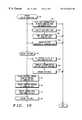
- FIG. 6shows a flow chart of tasks included in a capability addressable connection process performed by a peer
- FIG. 7shows a data format diagram of an exemplary need/capability message communicated from a peer to initiate a setup connection
- FIG. 8shows an exemplary need table which identifies possible network service needs which might occur at a peer
- FIG. 9shows an exemplary capability table which identifies possible network capabilities which may be provided by a peer
- FIG. 10shows a flow chart of a process service connection procedure performed at a peer
- FIG. 11shows a flow chart of tasks included in a capability addressable connection process for initiating communications between peers
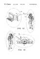
- FIG. 12illustrates a first example whereby the capability addressable connection process establishes communications between a computer and a personal presence identifier
- FIG. 13illustrates a second example whereby the capability addressable connection process establishes communications between a doorbell and the personal presence identifier
- FIG. 14is a diagram that illustrates a capability addressable connection between two peers.
- FIG. 1shows a layout diagram depicting relationships between various peers (P) 20 in a capability addressable, wireless, peer-to-peer data communication network 22 configured in accordance with the teaching of the present invention. While FIG. 1 shows only a few peers 20 , virtually any computer or microprocessor controlled electronic device throughout the world may serve as a peer 20 . Accordingly, network 22 supports an unfathomable number of possible connections between peers 20 .
- peer-to-peeris defined to mean having at least common portions of communications protocol and/or capability and does not refer to equivalence of physical size, functional capability, data processing capacity or transmitter/receiver range or power.
- Each peer or communication node 20 of communications network 22may establish a personal area network. For example, a first and a second of nodes 20 first find or determine that each other is a compatible node. Then, as a result of self-initiated processes, first and second nodes 20 form the personal network. First and second nodes 20 must detect that they are in a particular proximity to one another and if so a communication link is established. This link may be accomplished by known RF techniques.
- first and second nodes 20exchange what their needs and capabilities are. When needs and capabilities are not able to be satisfied or matched, one of first and second nodes 20 may alternately route the communications link to a third communication node 20 .
- a communications platformthat includes at least two nodes having overlapping communications regions could also include means for exchanging needs and capabilities information between the at least two nodes for forming a communication network.
- Network 22is desirably configured in a peer-to-peer architecture so that only a trivial amount of network-specific components are used.
- each peer 20can initiate a connection with other peers 20 without servers being required to manage the connections.
- peers 20can freely move about without affecting the network structure or requiring the performance of reconfiguration, setup, or activation procedures.
- wireless communication links 26are RF links operating in the higher regions of the microwave band so that small, lightweight, inexpensive, omni-directional antennas may be used. However, other RF frequencies, optical links, and other wireless communication links known to those skilled in the art may be used as well.
- the specific protocols used in implementing wireless communication links 26are not important to the present invention. Various TDMA, FDMA, and/or CDMA techniques known to those skilled in the art may be employed. However, all peers 20 in network 22 desirably have the ability to communicate using the protocols, regardless of the capabilities and needs of the peers 20 .
- FIG. 1depicts a detection zone 28 surrounding each peer 20 .
- wireless communication links 26 for the vast majority of peers 20are operated at a sufficiently low power so that a wireless communication range for a given peer 20 is limited to being less than 50 meters, and more preferably to being less than about 5 meters for the typical peer 20 .
- the use of this degree of low power transmissionslimits interference between independent connections which may share the wireless spectrum at different locations.
- the use of this degree of low power transmissionsis compatible with configuring a substantial portion of peers 20 as portable devices.
- hand-portable electronic devicesshare the characteristics of being physically small, lightweight, and including a self-contained power source such as a battery. Extremely low power transmissions do not severely deplete the reserves of small batteries typically used in portable devices.
- network 22uses physical proximity along with a needs and capabilities evaluation (discussed below) to target a peer 20 with which a connection is desired.
- a needs and capabilities evaluationdiscussed below
- network addressingbecomes dynamically configurable. Such an addressing scheme is useful in exchanging data between devices a user carries and comes into contact with on a daily basis.
- FIG. 1shows a wireline communication link 30 connecting a peer 20 ′ to a public switched telecommunication network (PSTN) 32 .
- PSTNpublic switched telecommunication network
- peer 20 ′may communicate with a vast assortment of remote devices 34 , of which FIG. 1 shows only one.
- Peer 20 ′may be powered from a public power network (not shown) so that minimizing power consumption is not a significant design issue.
- FIG. 1depicts only PSTN 32 linking a peer 20 to a remote device 34
- LANlocal area network
- WANwide area network
- Remote devices 34may or may not themselves be peers 20 .
- network 22uses proximity as a factor in targeting peers 20 to which connections are formed, the use of routing, gateway or relaying peers 20 ′ permits connections to be extended over great distances through the use of other networks.
- FIG. 2shows a block diagram of hardware included in a peer 20 .
- Peer 20includes an antenna 36 configured to support wireless communication link 26 .
- Antenna 36couples to a transmit and receive section 38 .
- Transmit and receive section 38is compatible with the protocols peers 20 use to communicate with one another.
- Transmit and receive section 38couples to a processor 40 .
- Processor 40couples to a memory 42 , an optional relay interface 44 , an optional I/O section 46 , and optional appliance circuits 48 .
- Processor 40executes computer programs 50 which are stored in memory 42 .
- Computer programs 50define processes performed by processor 40 and peer 20 .
- Memory 42additionally stores personalization data 52 and application data 54 .
- Personalization data 52characterize a user or owner of peer 20 and may change from user to user.
- ID codes, passwords, and PINsare examples of personalization data as are radio or TV channel presets, language preferences, and speed dial telephone numbers.
- Application data 54are provided by performing peer applications, and may change from moment to moment. A facsimile, a telephone number received over a pager, data scanned in using a bar code reader, and a sound snippet received from a microphone or other audio source represent examples of application data.
- FIG. 3shows a non-exhaustive list of examples of appliance circuits 48 which may be included in a peer 20 .
- appliance circuits 48may be configured as any type of a wide variety of everyday, commonly encountered electronically controlled devices.
- a peer 20may, in addition to being a peer 20 , be a personal digital assistant (PDA), smartcard, television, radio, CD player, tape player, copier, facsimile machine, telephone, cellular telephone, cordless telephone, pager, watch, computer, point of sale (POS) terminal, automated teller, or other electronic device.
- PDApersonal digital assistant
- FIG. 4shows a non-exhaustive list of relay interfaces 44 which may be included in a peer 20 .
- relay circuits 44may be configured as any of a wide variety of relay, routing, or gateway devices known to those skilled in the art.
- a peer 20may, in addition to being a peer 20 , be a modem which couples peer 20 to PSTN 32 (see FIG. 1 ).
- Other relay interfaces 44may couple a peer 20 to LANs or WANs.
- Still other relay interfaces 44may couple a peer 20 modem to a satellite, a peer 20 cell phone to PSTN 32 , a plain old telephone (POT) peer 20 to PSTN 32 , or a peer 20 to another peer 20 .
- POTplain old telephone
- FIG. 5shows a non-exhaustive list of I/O devices 46 which may be included in a peer 20 .
- I/O devices 46may be classified into input devices and output devices.
- Input devicesmay include keyboards, pointing devices, optical scanners, microphones, and other well known input devices.
- Output devicesmay include printers, monitors, speakers, and other well known output devices.
- a peer 20may be an I/O device 46 .
- relay interface section 44I/O section 46 and appliance circuits 48 are not mutually exclusive categories. For example, many devices fall into multiple categories. For example, a computer considered as an appliance may include both an I/O section and a relay interface. Likewise, a relay interface may serve an I/O role.
- FIG. 6shows a flow chart of tasks included in a capability addressable connection process 56 performed by a peer 20 .
- Process 56is defined by a computer program 50 stored in memory 42 of peer 20 (see FIG. 2) in a manner well known to those skilled in the art. In the preferred embodiments, all peers 20 perform a process similar to process 56 .
- Process 56includes a query task 58 during which peer 20 determines whether a setup connection is being attempted.
- task 58allows a first peer 20 to determine whether a second peer 20 is physically proximate to the first peer 20 .
- Task 58causes transmit and receive section 38 (see FIG. 2) to monitor wireless communication link 26 (see FIG. 1) to determine whether a signal compatible with a protocol being used by network 22 (see FIG. 1) can be received. Due to the above-described low transmission power levels used by peers 20 , when a signal is detected, the peer 20 sending the signal is located near the receiving peer 20 .
- a query task 60determines whether a connection-seeking event has occurred.
- a connection-seeking eventcauses a peer 20 to seek out a connection with another peer 20 .
- Connection-seeking eventscan be triggered using a periodic schedule. For example, connections may be sought out every few seconds. In this example, the schedule may call for more frequent periodic connection attempts from peers 20 which are powered from a public power network and less frequent connection attempts from peers 20 which are battery powered. Connection-seeking events can also be triggered upon the expiration of a timer or upon the receipt of other external information.
- the other external informationcan include information obtained through appliance circuits 48 , relay interface 44 , or I/O section 46 (see FIG. 2) including user input.
- task 60fails to determine that a connection-seeking event has occurred, program control loops back to task 58 . If task 60 determines that a connection-seeking event has occurred, process 56 performs a task 62 . Task 62 initiates an unsolicited setup connection.
- the setup connectionis not addressed to any particular peer 20 of network 22 . Rather, it is broadcast from the peer 20 making the attempt and will be received by all peers 20 within the detection zone 28 (see FIG. 1) of the broadcasting peer 20 . As discussed below, the broadcast signal need not be answered by another peer 20 even when another peer 20 is in detection zone 28 . At this point, the broadcasting peer 20 does not know if any other peer 20 can receive the broadcast signal, and the broadcasting peer 20 does not know any particular needs or capabilities of other peers 20 should other peers 20 be sufficiently proximate so that a connection may be formed.
- Task 62initiates a setup connection by broadcasting a need/capability message 64 , an exemplary format for which is depicted in FIG. 7 .
- message 64includes an ID 66 for the peer 20 broadcasting message 64 , an authorization key 68 , a need specification 70 , a capability specification 72 , and can include other data elements.
- ID 66is desirably sufficiently unique within the domain of network 22 so that it may be used in an addressed service connection, should the setup connection prove successful.
- Authorization key 68includes one or more data codes which may be used by a receiving peer 20 in performing an authorization process.
- Needs specification 70is a list of network needs currently experienced by the broadcasting peer 20 .
- Capability specification 72is a list of network capabilities which the broadcasting peer 20 may provide to other peers 20 of network 22 .
- Needs specification 70may be determined by consulting a need table 74 , an exemplary and non-exhaustive block diagram of which is depicted in FIG. 8 . As illustrated in FIG. 8, data codes may be associated with a variety of network service needs which a service-requesting peer 20 may experience.
- appliance personalizationIn the appliance personalization need example, a PDA might need to personalize nearby appliances. To satisfy this need, personalization data 52 (see FIG. 2) should be programmed into certain nearby appliances without user intervention. As a result, the certain appliances will always be programmed with a particular user's personalization data whenever that user is near, without requiring action on the user's part, and regardless of prior persons who may have used the appliance.
- exemplary needscan include that of printing application data 54 (see FIG. 2 ), displaying application data 54 , annunciating application data 54 at a speaker, routing connectivity to the Internet or other network resources, POS transactions, passage through secure areas or toll booths, and the like.
- Capability specification 72may be determined by consulting a capability table 76 , an exemplary and non-exhaustive block diagram of which is depicted in FIG. 9 .
- data codesmay be associated with a variety of network capabilities provided by a service-providing peer 20 .
- a service-providing peer 20 capabilitycan be that of appliance personalization.
- a peer 20may be capable of being personalized by personalization data 52 (see FIG. 2 ).
- Other examplesinclude capabilities of printing, displaying, annunciating over a speaker, relaying a connection through the Internet or other network, POS terminal, and unlocking a secured passageway, to name a few.
- potential capabilitiesare compatible with potential needs.
- need/capability message 64includes those codes from tables 74 and 76 (see FIGS. 8-9) that currently apply. While a peer 20 may have more than one need or capability at a given instant, nothing requires a peer 20 to have multiple needs or capabilities. Moreover, nothing requires a peer 20 to have both a network need and a network capability. Message 64 serves as a need message if a network need is specified regardless of whether a network capability is specified and as a capability message if a network capability is specified regardless of whether a network need is specified.
- Task 78uses authorization key 68 (see FIG. 7) from message 64 to determine if the peer 20 attempting to setup a connection is authorized to connect to the receiving peer 20 .
- Task 78allows an owner of a peer 20 to restrict access to the owned peer 20 through network 22 .
- the authorization process of task 78may be used, for example, to restrict personalization capabilities of an appliance to a small family group. Alternatively, a peer 20 having a POS capability may perform an extensive authorization process before permitting a transaction to take place. A peer 20 having a need may also qualify the receipt of provided services depending upon the authorization process provided by task 78 .
- a query task 80determines whether the authorization process 78 authorized the attempted setup connection. If authorization is denied, program control loops back to task 60 . The receiving peer 20 need not reply or otherwise acknowledge the attempted setup connection.
- a task 82evaluates peer needs with peer capabilities. In other words, task 82 causes the message-receiving peer to compare its available capabilities (if any) to any needs listed in a received unsolicited need/capability message 64 (see FIG. 7) and to compare its available needs (if any) to any capabilities listed in the message 64 .
- a query task 84acts upon the result of the evaluation of task 82 . If no internal capabilities match needs indicated in an unsolicited message 64 , and if no internal needs match capabilities indicated in an unsolicited message 64 , then neither peer 20 can be of service to the other. Program control loops back to task 60 , and the receiving peer 20 need not reply or otherwise acknowledge the attempted setup connection.
- the low power transmission schemeexcludes most peers 20 in network 22 from being connectable at a current instant because most peers 20 will not be proximate one another. Of the few peers 20 which may be within each other's detection zones 28 (see FIG. 1 ), the scope of potential connections has been further limited through the authorization process of task 78 and needs and capabilities evaluation of task 82 . Additional exclusions on the remaining potential connections are performed through a negotiation process carried on between a service-requesting peer 20 and a service-providing peer 20 .
- a query task 86determines whether this negotiation process is complete. If the negotiation process is not complete, a task 88 establishes or otherwise continues the setup connection in furtherance of the negotiation process by sending an addressed negotiation message (not shown) to the peer 20 whose peer ID 66 (see FIG. 7) was included in a just-received needs/capabilities message 64 .
- the negotiation messagecan have a form similar to that of needs/capabilities message 64 , but be specifically addressed to the other peer 20 .
- program controlloops back to task 60 .
- Subsequent negotiation messagesmay, but need not, be received. If such subsequent negotiation messages indicate that both peers 20 to the prospective connection have completed negotiation, a query task 90 determines whether the negotiation was successful. If the negotiation was not successful, program control loops back to task 58 , and no service connection will result. However, if the negotiation was successful, a process service connection procedure 92 is performed. During procedure 92 , a one-to-one, addressed connection is established between peers 20 to perform network services. Upon completion of the service connection, program flow loops back to task 58 .
- FIG. 10shows a flow chart of process service connection procedure 92 .
- Procedure 92illustrates a collection of tasks which can be performed at a service-providing peer 20 in support of a service connection. Not all peers 20 need to be able to perform all the tasks depicted in FIG. 10 . Likewise, many peers 20 may include other tasks which suit the nature of those particular peers 20 .
- Procedure 92performs a task 94 to provide a network relay, router, or gateway capability for a service-receiving peer 20 of network 22 through an established service connection.
- a service-providing peer 20relays data communications between the connected peer 20 and a remote device 34 (see FIG. 1 ).
- program flowreturns to process 56 (see FIG. 6 ).
- Task 94may be used to extend the service connection to the Internet or other network.
- Procedure 92performs tasks 96 and 98 to provide a user input capability for a service-receiving peer 20 of network 22 through an established service connection.
- the service-providing peer 20collects user input from its I/O section 46 (see FIG. 2 ).
- the service-providing peer 20sends the collected user input data to the connected service-receiving peer 20 .
- program flowreturns.
- Tasks 96 and 98may be used to control or program appliances from a PDA or other device which may have enhanced user input capabilities.
- Procedure 92performs a task 100 to provide a user output capability for a service-receiving peer 20 of network 22 through an established service connection.
- the service-providing peer 20receives data generated from the service-receiving peer 20 over the service connection and annunciates the data at an output device in its I/O section 46 (see FIG. 2 ).
- the datamay be annunciated in an audibly or visibly perceivable format or in any other format perceivable by human senses.
- program flowreturns.
- Task 100may be used to annunciate data collected in a portable peer 20 at a non-portable annunciating device.
- task 100may be used to annunciate data generated by a stationary appliance with limited I/O capability at a portable annunciating device.
- Procedure 92performs a control appliance process 102 to support the controlling of appliances.
- Tasks 104 , 106 , and 108 of process 102are performed to program an appliance peer 20 with personalization data 52 (see FIG. 2 ).
- a service-providing peer 20gets personalization data 52 from the connected, service-receiving peer 20 using the service connection.
- task 106translates the network compatible personalization data 52 into a format suitable for the specific appliance to be programmed with personalization data 52 . It should be noted that not all personalization data 52 available in a service-receiving peer 20 needs to be applicable to all appliances. Thus, task 106 can use as much of personalization data 52 as applies to the specific appliance.
- task 108causes the appliance to be programmed with the translated personalization data 52 .
- program flowreturns.
- Tasks 110 , 112 , 114 , and 116 of process 102are performed to allow a user to easily control an appliance. These tasks can be performed on a PDA, for example, which has a display and user input capability exceeding the user I/O capabilities typically found on appliances.
- an applianceis a service-receiving peer 20 while the PDA is a service-providing peer 20 .
- the service-receiving peer 20uploads an appliance control computer program to the connected service-providing peer using the service connection.
- the service-providing peer 20executes the just-uploaded computer program.
- Task 112causes the service-providing peer 20 to become specifically configured to provide a desirable user interface for the specific appliance being controlled.
- control dataare received at the service-receiving peer 20 over the service connection.
- the control dataoriginated from user input supplied through the control computer program being executed on the service-providing peer 20 .
- task 116controls the subject appliance in accordance with the control data received in task 114 .
- program flowreturns.
- FIG. 11is a flow chart providing further detail of the capability addressable coupling process as shown in FIG. 6 .
- FIG. 11illustrates a method of initiating a communication link between first and second electronic devices or first and second peers 20 .
- task 58causes transmit and receive section 38 to monitor wireless communication link 26 to determine whether a signal compatible with a protocol being used by network 22 can be received.
- task 58 of FIG. 11indicates that a setup connection or coupling process in transmitting a beacon message from a first peer 20 is received by a second peer 20 .
- the beacon message transmitted by the first peer 20is an unsolicited message that is broadcast to any listening electronic device.
- the type of information transmitted in the beacon messageis not a limitation of the present invention.
- the beacon messagemay or may not include all of the elements in need/capability message 64 as illustrated in FIG. 7 .
- the beacon messagecould only include the peer ID 66 portion of need/capability message 64 in order to save bandwidth and power when transmitting data.
- the first peer 20transmits a beacon message, i.e., the identity of the first peer 20 as contained in peer ID 66 , as an unsolicited periodic message independent of whether any other electronic device is within a close enough proximity to receive the message.
- Task 78 A of FIG. 11causes second peer 20 to perform an authorization of the identity message received from the first peer 20 . If authorized to establish a communications link as determined by task 80 A, second peer 20 sends or transmits an associate message as indicated by task 81 to first peer 20 . Thus, second peer 20 acknowledges receipt of the identity of first peer 20 based on authorization of the second peer 20 to communicate with the first peer 20 by transmitting an associate message from second peer 20 . If not authorized to establish a communications link, no associate message is transmitted and second peer 20 returns from task 80 A (see FIG. 11) to task 60 (see FIG. 6 ).
- the associate message sent by the second peer 20 to the first peer 20confirms that second peer 20 is authorized to communicate with first peer 20 based on the transmitted identity of the first electronic device.
- First peer 20receives the associate message and moves from task 61 to task 78 B.
- Task 78 B(also see task 78 in FIG. 6) causes first peer 20 to determine whether authorization is granted for the first peer 20 to establish communications with the second peer 20 . If authorization is granted then the first peer 20 moves from task 80 B to task 63 (FIG. 11 ).
- Task 63causes first peer 20 to send or transmit an associate confirm message to second peer 20 .
- first peer 20acknowledges both a receipt of the associate message from second peer 20 and a granted authorization of first peer 20 to communicate with second peer 20 by transmitting an associate confirm message.
- second peer 20receives the associate confirm message in task 83 , the two-way communications link between first peer 20 and second peer 20 is established.
- Task 82 in FIG. 11corresponds with task 82 in FIG. 6, which causes an exchange of needs and capabilities between first peer 20 and second peer 20 .
- the first peer 20transmits its needs and capabilities to the second peer 20 and the second peer 20 transmits its needs and capabilities to the first peer 20 .
- a need of peer 20is defined as a need for service. It may be that the need for service is an operation that is desired to be performed on the data of peer 20 but peer 20 is not capable of performing the desired operation. For example, it may be desired that the data be displayed but peer 20 does not have a display for viewing the data.
- a capability of peer 20is defined as a capability to perform a service.
- the capability for serviceincludes an operation that peer 20 is capable of performing.
- peer 20may be desired that the data in peer 20 be encrypted for security reasons and peer 20 has an encryption circuit.
- the peer 20 with the encryption circuithas a capability of encrypting data that can be offered as an operation to other peers without the encryption circuit.
- FIG. 12illustrates a first example whereby the capability addressable connection process establishes communications between two peers 20 , i.e., a computer 120 and a personal presence identifier 122 .
- Personal presence identifier 122is a specific peer 20 such as an electronic watch, an electronic wallet, a bracelet, a portable cellular phone, or a pager that has the capability of establishing a communications protocol with another peer 20 , i.e., computer 120 .
- computer 120 and personal presence identifier 122reside within each others detection zone 28 , they are interlinked via, for example, RF interconnections, represented as wireless communication links 26 .
- computer 120 and personal presence identifier 122each execute query task 58 of process 56 (FIG. 6 ).
- Task 58determines that computer 120 and personal presence identifier 122 have transmitted an unsolicited and periodic beacon message in attempting to setup a connection and are residing within each others detection zone 28 .
- Task 58causes transmit and receive section 38 (FIG. 2) to monitor wireless communication link 26 to determine whether a signal compatible with a protocol being used by communications network 22 (FIG. 1) is received.
- computer 120 and personal presence identifier 122transmit associate messages and associate confirm messages in establishing a personal area network (see tasks described in FIG. 11 ).
- Need table 74contains examples of items in needs specification 70 and capability table 76 (FIG. 9) contains examples of items in capability specification 72 for computer 120 .
- personal presence identifier 122transmits needs specification 70 and capability specification 72 as the portion of need/capability message 64 of FIG. 7 to computer 120 .
- Need table 74(FIG. 8) contains examples of items in needs specification 70 and capability table 76 (FIG. 9) contains examples of items in capability specification 72 for personal presence identifier 122 .
- a need of computer 120is a service that computer 120 needs performed.
- the servicemay include a function that computer 120 is not capable of performing or authorized to perform, such as providing a password that enables or allows a user access to files, data, and programs stored on computer 120 .
- personal presence identifier 122establishes communications network 22 (FIG. 1) with computer 120 and in addition, provides authorization that instructs computer 120 to have an active keyboard and screen and provide access to user's computer files.
- a capability of personal presence identifier 122is a service or function that personal presence identifier 122 is capable of performing.
- personal presence identifier 122stores information on the user's computer home directories, font styles, files, etc., which is transferred from personal presence identifier 122 to computer 120 without user intervention.
- Tasks 104 , 106 and 108 of process 102are performed to program computer 120 with personalization data 52 (FIG. 2) from personal presence identifier 122 .
- computer 120gets personalization data 52 from the service connection with personal presence identifier 122 .
- task 106translates the network compatible personalization data 52 into a format appropriate for computer 120 .
- computer 120is programmed with a particular user's personalization data whenever that user is in close proximity to computer 120 and authorized to use computer 120 , without requiring action on the user's part, and regardless of prior persons who may have used computer 120 .
- wireless communication link 26is automatically established when an authorized user with the personal presence identifier 122 is within detection zone 28 of computer 120 . Further, as long as computer 120 and personal presence identifier 122 remain in close proximity, computer 120 remains active to the user identified by personal presence identifier 122 . However, computer security is further enhanced because wireless communication link 26 between personal presence identifier 122 and computer 120 is broken when personal presence identifier 122 is removed from the close proximity with computer 120 . Wireless communication link 26 is immediately broken when the user with the personal presence identifier 122 leaves detection zone 28 of computer 120 .
- FIG. 13illustrates a second example whereby the capability addressable connection process establishes communications between two peers 20 , i.e., a door entry system 130 and a personal presence identifier 122 .
- Door entry system 130is an electronic device such as a doorbell system that has the communications protocol of peer 20 .
- door entry system 130is externally mounted at the front entry of a residence.
- RF interconnectionsrepresented as wireless communication link 26 .
- a handicapped person or safety conscience person wearing personal presence identifier 122can establish the personal area network without having to physically push the doorbell.
- door entry system 130 and personal presence identifier 122each execute query task 58 of process 56 (FIG. 6 ).
- Task 58determines that door entry system 130 and personal presence identifier 122 are each attempting to setup a connection by transmitting unsolicited and periodic beacon messages and each resides within the others detection zone 28 .
- Task 58causes transmit and receive section 38 (FIG. 2) to monitor wireless communication link 26 to determine whether a signal compatible with a protocol being used by communications network 22 (FIG. 1) is received.
- door entry system 130 and personal presence identifier 122transmit associate messages and associate confirm messages in establishing a personal area network (see tasks described in FIG. 11 ).
- Door entry system 130 and personal presence identifier 122have several possible options when operating together.
- a first optionis that door entry system 130 reads peer ID 66 (FIG. 7) of personal presence identifier 122 to determine the identity of the person wearing personal presence identifier 122 .
- the identity of the personcould then be displayed on a service-providing peer 20 within the residence which is capable of displaying information received from door entry system 130 .
- Service-providing peer 20would log the identity found in peer ID 66 (FIG. 7) of each person having a personal presence identifier 122 that attempts a setup connection via door entry system 130 .
- a second optioninvolves receiving a note intended only for the person residing at the resident. For instance, a delivery service may want to leave a private message explaining possible options after finding no one at home. After establishing the identity of the delivery service personnel who is wearing personal presence identifier 122 , door entry system 130 could receive a message entered though personal presence identifier 122 by the delivery service personnel. The message would then be displayed on a service-providing peer 20 within the residence which is capable of displaying information received from door entry system 130 .
- a third optioninvolves the home owner leaving a message for the delivery service personnel that has a specific identification designator programmed in the personal presence identifier 122 .
- the residentmay want to leave a private message with the delivery service after establishing the identity of the person wearing personal presence identifier 122 .
- door entry system 130enhances the security of the resident by allowing private messages to be communicated.
- a wireless communication link 26is automatically established when a user with the personal presence identifier 122 is within detection zone 28 of door entry system 130 .
- the identity of the user with the personal presence identifier 122is available to the residence of the home serviced by door entry system 130 .
- FIG. 14illustrates a third example of the capability addressable connection process that establishes communications between two peers 20 , i.e., a peer 132 as an electronic take-a-number device and personal presence identifier 122 .
- the electronic take-a-number devicei.e., virtual queuing system
- the personal presence identifier 122each attempt to setup a connection by transmitting unsolicited and periodic beacon messages.
- Associate messages and associate confirm messagesare exchanged between the electronic take-a-number device and personal presence identifier 122 to establish link 26 (see tasks described in FIG. 11) when the two peers are in close proximity to each other.
- Certain servicesare provided in a sequential order based on a queue system.
- personal presence identifier 122forms link 26 and is registered with the electronic take-a-number device, information is transferred to personal presence identifier 122 by the electronic take-a-number device.
- the informationfor example, includes position in the queue, expected wait time, notification of reaching the head of the queue, registration in other queues when necessary, financial cost of an expected transaction, etc.
- the virtual queuing systemuses proximity-based short-range wireless links and comprises the peer device 132 arranged and programmed for maintaining a virtual queue for an event, such as an amusement ride, taking place at a venue, and the personal presence identifier 122 carried by a user and coupled to the peer device 132 by a short-range two-way wireless link.
- the peer device 132 and the personal presence identifier 122are arranged and programmed to establish a two-way personal area network with one another when the personal presence identifier 122 is within wireless transmission range of the peer device 132 .
- the personal presence identifier 122 and the peer device 132are also arranged and programmed to exchange needs specifications and capability specifications with one another after establishing the two-way personal area network.
- the peer device 132is further arranged and programmed through well-known techniques to provide support for a logical queue for the event.
- the peer device and the personal presence identifier 122are further arranged and programmed to cooperate to place an identifier of the personal presence identifier 122 into the logical queue, in response to a request from the personal presence identifier 122 .
- the peer device 132is further arranged and programmed to send to the personal presence identifier 122 an estimated waiting time to access the event. In another embodiment, the peer device 132 is further arranged and programmed to send to the personal presence identifier 122 a cost of accessing the event. In yet another embodiment, the peer device 132 is further arranged and programmed to send to the personal presence identifier 122 an alert when an estimated time to reach the event is less than a predetermined time. This advantageously allows the user of the personal presence identifier 122 to move to the event and, for example, to enter a physical queue for the event.
- the peer device 132preferably is further arranged and programmed to multiplex with a plurality of personal presence identifiers 122 for maintaining a corresponding plurality of positions in the virtual queue. This allows a plurality of users to interact with the virtual queuing system simultaneously.
- the peer device 132 and the personal presence identifier 122also preferably are arranged and programmed to have an exchange of information about the user and a payment method, the exchange of information transparent to the user.
- the personal presence identifier 122comprises a timer for generating an alert indicating that the user should approach the venue of the event. This feature is advantageous, for example, when the personal presence identifier 122 has moved out of communication range with the peer device 132 .
- the peer device 132 and the personal presence identifier 122preferably are further arranged and programmed to exchange information defining how many people are associated with the personal presence identifier 122 .
- the peer device 132then queues a corresponding number of positions in the virtual queue.
- the peer device 132 and the personal presence identifier 122are further arranged and programmed to exchange user attributes affecting participation in the event. For example, an amusement ride may be considered too dangerous for children under six years old.
- the virtual queuing systemwould then check the age of potential riders and would disallow those under six years old.
- the peer device 132 and the personal presence identifier 122are arranged and programmed to stop advancing the user's position in the virtual queue when further advancement would require the user to approach the venue of the event, and when the user is performing a predetermined activity. This feature is useful, for example, for preventing an interruption of an activity such as shopping or dining, which may be deemed more important than the queued event.
- the peer device 132 and the personal presence identifier 122are further arranged and programmed to utilize the personal presence identifier 122 as a key for entering a physical queue at the event. For example, a code downloaded to the personal presence identifier 122 can unlock a turnstile at the event.
- the peer device 132 and the personal presence identifier 122preferably are further arranged and programmed to provide for dispensing of a virtual ticket to the personal presence identifier 122 , and the personal presence identifier 122 is further arranged and programmed to display the virtual ticket for presentation to a person guarding the entryway to the event.
- the peer device 132 and the personal presence identifier 122are further arranged and programmed to display seating information on a display of the personal presence identifier 122 and to allow seating selection by the user.
- the peer device 132 and the personal presence identifier 122preferably are further arranged and programmed to provide for selection of special needs accommodations, such as handicapped seating.
- the peer device 132 and the personal presence identifier 122preferably are further arranged and programmed to provide a waiting list function for desired seating when the desired seating is unavailable and alternate seating has been purchased.
- the peer device 132 and the personal presence identifier 122preferably are arranged and programmed to display information related to the event on a display of the personal presence identifier 122 . For example, a program for the event or player statistics can be displayed.
- the peer device 132 and the personal presence identifier 122are further arranged and programmed to provide for ordering items, e.g., food, drinks, and souvenirs, to be delivered to the user during the event.
- the peer device 132 and the personal presence identifier 122are preferably arranged and programmed to allow a selection of an event from multiple discrete events.
- the peer device 132is one of a plurality of networked peer devices, and the event is one of a plurality of events.
- the plurality of networked peer devices and the personal presence identifier 122are preferably arranged and programmed to allow purchasing tickets for any of the plurality of events through any of the plurality of networked peer devices.
- the present inventionprovides a virtual queuing system using proximity-based short-range wireless links.
- the virtual queuing systemadvantageously provides support for logical queues, thereby allowing users to queue for events and services without having to wait in a physical queue. The user is free to participate in other activities while the virtual queuing system maintains the user's position in the queue.
- the virtual queuing systemadvantageously provides for the electronic dispensing of tickets to events.
Landscapes
- Engineering & Computer Science (AREA)
- Computer Networks & Wireless Communication (AREA)
- Signal Processing (AREA)
- Computer Hardware Design (AREA)
- Computer Security & Cryptography (AREA)
- Computing Systems (AREA)
- General Engineering & Computer Science (AREA)
- Mobile Radio Communication Systems (AREA)
Abstract
Description
Claims (20)
Priority Applications (4)
| Application Number | Priority Date | Filing Date | Title |
|---|---|---|---|
| US09/454,846US6424623B1 (en) | 1996-10-15 | 1999-12-07 | Virtual queuing system using proximity-based short-range wireless links |
| AU19481/01AAU1948101A (en) | 1999-12-07 | 2000-12-06 | Virtual queuing system using proximity-based short-range wireless links |
| GB0211463AGB2376850B (en) | 1999-12-07 | 2000-12-06 | Virtual queuing system using proximity-based short-range wireless links |
| PCT/US2000/033032WO2001043316A1 (en) | 1999-12-07 | 2000-12-06 | Virtual queuing system using proximity-based short-range wireless links |
Applications Claiming Priority (3)
| Application Number | Priority Date | Filing Date | Title |
|---|---|---|---|
| US08/729,207US6069896A (en) | 1996-10-15 | 1996-10-15 | Capability addressable network and method therefor |
| US09/104,631US6421347B1 (en) | 1996-10-15 | 1998-06-25 | Capability addressable network and method therefor |
| US09/454,846US6424623B1 (en) | 1996-10-15 | 1999-12-07 | Virtual queuing system using proximity-based short-range wireless links |
Related Parent Applications (1)
| Application Number | Title | Priority Date | Filing Date |
|---|---|---|---|
| US09/104,631Continuation-In-PartUS6421347B1 (en) | 1996-10-15 | 1998-06-25 | Capability addressable network and method therefor |
Publications (1)
| Publication Number | Publication Date |
|---|---|
| US6424623B1true US6424623B1 (en) | 2002-07-23 |
Family
ID=23806338
Family Applications (1)
| Application Number | Title | Priority Date | Filing Date |
|---|---|---|---|
| US09/454,846Expired - LifetimeUS6424623B1 (en) | 1996-10-15 | 1999-12-07 | Virtual queuing system using proximity-based short-range wireless links |
Country Status (4)
| Country | Link |
|---|---|
| US (1) | US6424623B1 (en) |
| AU (1) | AU1948101A (en) |
| GB (1) | GB2376850B (en) |
| WO (1) | WO2001043316A1 (en) |
Cited By (57)
| Publication number | Priority date | Publication date | Assignee | Title |
|---|---|---|---|---|
| US20030147369A1 (en)* | 2001-12-24 | 2003-08-07 | Singh Ram Naresh | Secure wireless transfer of data between different computing devices |
| US20040046637A1 (en)* | 2000-05-23 | 2004-03-11 | Eveline Wesby Van Swaay | Programmable communicator |
| US20040082383A1 (en)* | 2002-10-24 | 2004-04-29 | Motorola, Inc | Methodology and wireless device for interactive gaming |
| US20040158482A1 (en)* | 1999-08-10 | 2004-08-12 | Hale Gregory B. | Management of the flow of persons in relation to centers of crowd concentration via wireless corntrol |
| US20040172316A1 (en)* | 1999-08-10 | 2004-09-02 | Hale Gregory B. | Management of the flow of persons in relation to centers of crowd concentration via priority control |
| US20040172315A1 (en)* | 1999-08-10 | 2004-09-02 | Hale Gregory B. | Management of the flow of persons in relation to centers of crowd concentration |
| US20040181424A1 (en)* | 1999-08-10 | 2004-09-16 | Hale Gregory B. | Management of the flow of persons in relation to centers of crowd concentration via television control |
| US20040189470A1 (en)* | 2003-03-26 | 2004-09-30 | Girvin Joshua M. | Non-reusable identification device |
| US6804232B1 (en)* | 2000-03-27 | 2004-10-12 | Bbnt Solutions Llc | Personal area network with automatic attachment and detachment |
| US20050060173A1 (en)* | 1999-08-10 | 2005-03-17 | Hale Gregory B. | Management of the flow of persons in entertainment environments |
| US20050065834A1 (en)* | 1999-08-10 | 2005-03-24 | Hale Gregory B. | Management of the flow of passengers, baggage and cargo in relation to travel facilities |
| US6889098B1 (en) | 1999-08-10 | 2005-05-03 | Disney Enterprises, Inc. | Method and apparatus for managing attraction admission |
| US20050169219A1 (en)* | 2004-01-30 | 2005-08-04 | Mark Serpa | Method and system for peer-to-peer wireless communication over unlicensed communication spectrum |
| US6941270B1 (en)* | 1999-06-21 | 2005-09-06 | Nokia Corporation | Apparatus, and associated method, for loading a mobile terminal with an application program installed at a peer device |
| US20050289266A1 (en)* | 2004-06-08 | 2005-12-29 | Daniel Illowsky | Method and system for interoperable content player device engine |
| WO2006038071A1 (en) | 2004-10-07 | 2006-04-13 | Nokia Corporation | Method and apparatus for indicating proximity co-presence |
| US20060092028A1 (en)* | 2004-10-08 | 2006-05-04 | Proximities, Inc. | Identification band using shorting wire for enabling/disabling an RFID transponder contained thereon |
| US20060122925A1 (en)* | 2002-05-21 | 2006-06-08 | Wesby Philip B | System and method for remote asset management |
| US20060280149A1 (en)* | 2003-07-22 | 2006-12-14 | Carmen Kuhl | Reader device for radio frequency identification transponder with transponder functionality |
| US20070011870A1 (en)* | 2005-07-18 | 2007-01-18 | Lerch John W | Method of manufacture of an identification wristband construction |
| US20070120687A1 (en)* | 2005-11-29 | 2007-05-31 | Lerch John W | Identification band using a conductive fastening for enhanced security and functionality |
| US20070203763A1 (en)* | 1999-08-10 | 2007-08-30 | Jonathan Ackley | Management of the flow of persons and advertisement distribution via wireless media |
| US20070225911A1 (en)* | 2006-03-23 | 2007-09-27 | Rich Chanick | User positional and venue information integration system and method |
| US20070236350A1 (en)* | 2004-01-23 | 2007-10-11 | Sebastian Nystrom | Method, Device and System for Automated Context Information Based Selective Data Provision by Identification Means |
| US20070286220A1 (en)* | 2004-06-17 | 2007-12-13 | Stenning Norman V | Queue Management System and Method |
| US20080056722A1 (en)* | 2006-08-29 | 2008-03-06 | Hendrix John A | Binding methods and devices in a building automation system |
| US20080183875A1 (en)* | 2002-07-30 | 2008-07-31 | Sony Corporation | Program and information processing method and apparatus |
| US20080231428A1 (en)* | 2004-03-17 | 2008-09-25 | Carmen Kuhl | Continuous Data a Provision by Radio Frequency Identification (rfid) Transponders |
| US20080238617A1 (en)* | 2004-03-19 | 2008-10-02 | Carmen Kuhl | Detector Logic and Radio Identification Device and Method for Enhancing Terminal Operations |
| CN100426720C (en)* | 2004-09-24 | 2008-10-15 | 华为技术有限公司 | Method of implementing business ability negotiation |
| US20090005004A1 (en)* | 2000-05-05 | 2009-01-01 | Nokia Corporation | Communication devices and method of communication |
| US20110009075A1 (en)* | 2009-07-07 | 2011-01-13 | Nokia Corporation | Data transfer with wirelessly powered communication devices |
| US7979096B1 (en) | 2001-11-30 | 2011-07-12 | Tri-County Excelsior Foundation | Energy efficient forwarding in ad-hoc wireless networks |
| US20130173713A1 (en)* | 2012-01-02 | 2013-07-04 | Eric David Rich Anderson | Securing communications among friends with user-wearable mementos |
| US8606605B2 (en) | 2006-09-28 | 2013-12-10 | Lo-Q, Plc | Reservation management system and method |
| US20140156328A1 (en)* | 2012-11-30 | 2014-06-05 | Bank Of America Corporation | Transaction queuing |
| US9642219B2 (en) | 2014-06-05 | 2017-05-02 | Steelcase Inc. | Environment optimization for space based on presence and activities |
| US20170200319A1 (en)* | 2012-09-04 | 2017-07-13 | Zoomline Ip Holdings, Llc | Queue management system and method |
| US9716861B1 (en) | 2014-03-07 | 2017-07-25 | Steelcase Inc. | Method and system for facilitating collaboration sessions |
| US9766079B1 (en) | 2014-10-03 | 2017-09-19 | Steelcase Inc. | Method and system for locating resources and communicating within an enterprise |
| US9852388B1 (en) | 2014-10-03 | 2017-12-26 | Steelcase, Inc. | Method and system for locating resources and communicating within an enterprise |
| US9921726B1 (en) | 2016-06-03 | 2018-03-20 | Steelcase Inc. | Smart workstation method and system |
| US9955318B1 (en) | 2014-06-05 | 2018-04-24 | Steelcase Inc. | Space guidance and management system and method |
| US10152840B2 (en) | 2016-03-16 | 2018-12-11 | Universal City Studios Llc | Virtual queue system and method |
| US10264213B1 (en) | 2016-12-15 | 2019-04-16 | Steelcase Inc. | Content amplification system and method |
| TWI660603B (en)* | 2018-05-04 | 2019-05-21 | 神基科技股份有限公司 | Information-Capturing Device |
| US10304276B2 (en) | 2012-06-07 | 2019-05-28 | Universal City Studios Llc | Queue management system and method |
| US10433646B1 (en) | 2014-06-06 | 2019-10-08 | Steelcaase Inc. | Microclimate control systems and methods |
| US10664772B1 (en) | 2014-03-07 | 2020-05-26 | Steelcase Inc. | Method and system for facilitating collaboration sessions |
| US10733371B1 (en) | 2015-06-02 | 2020-08-04 | Steelcase Inc. | Template based content preparation system for use with a plurality of space types |
| US10943188B2 (en) | 2016-11-09 | 2021-03-09 | Universal City Studios Llc | Virtual queuing techniques |
| US11337047B1 (en) | 2002-05-21 | 2022-05-17 | M2M Solutions Llc | System and method for remote asset management |
| US11568333B2 (en) | 2019-06-27 | 2023-01-31 | Universal City Studios Llc | Systems and methods for a smart virtual queue |
| US11744376B2 (en) | 2014-06-06 | 2023-09-05 | Steelcase Inc. | Microclimate control systems and methods |
| US11847589B2 (en) | 2014-08-20 | 2023-12-19 | Universal City Studios Llc | Virtual queuing system and method |
| US11984739B1 (en) | 2020-07-31 | 2024-05-14 | Steelcase Inc. | Remote power systems, apparatus and methods |
| US12118178B1 (en) | 2020-04-08 | 2024-10-15 | Steelcase Inc. | Wayfinding services method and apparatus |
Families Citing this family (1)
| Publication number | Priority date | Publication date | Assignee | Title |
|---|---|---|---|---|
| JP4045536B2 (en)* | 2002-05-27 | 2008-02-13 | 日本電気株式会社 | Portable information terminal device |
Citations (9)
| Publication number | Priority date | Publication date | Assignee | Title |
|---|---|---|---|---|
| US5006983A (en) | 1989-09-12 | 1991-04-09 | Addax, Inc. | Service allocation system |
| US5502806A (en) | 1994-11-17 | 1996-03-26 | Mahoney; Timothy S. | Waiting line management system |
| US5724520A (en) | 1993-06-08 | 1998-03-03 | Anthony V. Pugliese | Electronic ticketing and reservation system and method |
| US5812955A (en)* | 1993-11-04 | 1998-09-22 | Ericsson Inc. | Base station which relays cellular verification signals via a telephone wire network to verify a cellular radio telephone |
| US5898831A (en)* | 1996-12-16 | 1999-04-27 | Motorola, Inc. | Interactive appliance security system and method |
| US5909183A (en)* | 1996-12-26 | 1999-06-01 | Motorola, Inc. | Interactive appliance remote controller, system and method |
| US5949777A (en)* | 1994-05-03 | 1999-09-07 | George Uyesugi | Wireless communication processor system |
| US5948040A (en) | 1994-06-24 | 1999-09-07 | Delorme Publishing Co. | Travel reservation information and planning system |
| US6069896A (en)* | 1996-10-15 | 2000-05-30 | Motorola, Inc. | Capability addressable network and method therefor |
- 1999
- 1999-12-07USUS09/454,846patent/US6424623B1/ennot_activeExpired - Lifetime
- 2000
- 2000-12-06WOPCT/US2000/033032patent/WO2001043316A1/enactiveApplication Filing
- 2000-12-06GBGB0211463Apatent/GB2376850B/ennot_activeExpired - Fee Related
- 2000-12-06AUAU19481/01Apatent/AU1948101A/ennot_activeAbandoned
Patent Citations (9)
| Publication number | Priority date | Publication date | Assignee | Title |
|---|---|---|---|---|
| US5006983A (en) | 1989-09-12 | 1991-04-09 | Addax, Inc. | Service allocation system |
| US5724520A (en) | 1993-06-08 | 1998-03-03 | Anthony V. Pugliese | Electronic ticketing and reservation system and method |
| US5812955A (en)* | 1993-11-04 | 1998-09-22 | Ericsson Inc. | Base station which relays cellular verification signals via a telephone wire network to verify a cellular radio telephone |
| US5949777A (en)* | 1994-05-03 | 1999-09-07 | George Uyesugi | Wireless communication processor system |
| US5948040A (en) | 1994-06-24 | 1999-09-07 | Delorme Publishing Co. | Travel reservation information and planning system |
| US5502806A (en) | 1994-11-17 | 1996-03-26 | Mahoney; Timothy S. | Waiting line management system |
| US6069896A (en)* | 1996-10-15 | 2000-05-30 | Motorola, Inc. | Capability addressable network and method therefor |
| US5898831A (en)* | 1996-12-16 | 1999-04-27 | Motorola, Inc. | Interactive appliance security system and method |
| US5909183A (en)* | 1996-12-26 | 1999-06-01 | Motorola, Inc. | Interactive appliance remote controller, system and method |
Cited By (187)
| Publication number | Priority date | Publication date | Assignee | Title |
|---|---|---|---|---|
| US6941270B1 (en)* | 1999-06-21 | 2005-09-06 | Nokia Corporation | Apparatus, and associated method, for loading a mobile terminal with an application program installed at a peer device |
| US7532941B2 (en) | 1999-08-10 | 2009-05-12 | Disney Enterprises, Inc. | Management of the flow of persons in relation to centers of crowd concentration via wireless control |
| US7720718B2 (en) | 1999-08-10 | 2010-05-18 | Disney Enterprises, Inc. | Management of the flow of persons in relation to centers of crowd concentration via television control |
| US20040158482A1 (en)* | 1999-08-10 | 2004-08-12 | Hale Gregory B. | Management of the flow of persons in relation to centers of crowd concentration via wireless corntrol |
| US20040172316A1 (en)* | 1999-08-10 | 2004-09-02 | Hale Gregory B. | Management of the flow of persons in relation to centers of crowd concentration via priority control |
| US20040172315A1 (en)* | 1999-08-10 | 2004-09-02 | Hale Gregory B. | Management of the flow of persons in relation to centers of crowd concentration |
| US20040181424A1 (en)* | 1999-08-10 | 2004-09-16 | Hale Gregory B. | Management of the flow of persons in relation to centers of crowd concentration via television control |
| US20070203763A1 (en)* | 1999-08-10 | 2007-08-30 | Jonathan Ackley | Management of the flow of persons and advertisement distribution via wireless media |
| US7222080B2 (en) | 1999-08-10 | 2007-05-22 | Disney Enterprises, Inc. | Management of the flow of persons in relation to centers of crowd concentration |
| US7400932B2 (en) | 1999-08-10 | 2008-07-15 | Disney Enterprises, Inc. | Management of the flow of persons and advertisement distribution via wireless media |
| US7787965B2 (en) | 1999-08-10 | 2010-08-31 | Disney Enterprises, Inc. | Management of the flow of persons in entertainment environments |
| US20050060173A1 (en)* | 1999-08-10 | 2005-03-17 | Hale Gregory B. | Management of the flow of persons in entertainment environments |
| US20050065834A1 (en)* | 1999-08-10 | 2005-03-24 | Hale Gregory B. | Management of the flow of passengers, baggage and cargo in relation to travel facilities |
| US6889098B1 (en) | 1999-08-10 | 2005-05-03 | Disney Enterprises, Inc. | Method and apparatus for managing attraction admission |
| US7801629B2 (en) | 1999-08-10 | 2010-09-21 | Disney Enterprises, Inc. | Management of the flow of passengers, baggage and cargo in relation to travel facilities |
| US7047205B2 (en) | 1999-08-10 | 2006-05-16 | Disney Enterprises, Inc. | Management of the flow of persons in relation to centers of crowd concentration via priority control |
| US8588196B2 (en)* | 2000-03-27 | 2013-11-19 | Tri-County Excelsior Foundation | Automatic attachment and detachment for hub and peripheral devices |
| US20050053065A1 (en)* | 2000-03-27 | 2005-03-10 | Bbnt Solutions Llc | Personal area network with automatic attachment and detachment |
| US9445260B2 (en)* | 2000-03-27 | 2016-09-13 | Azure Networks, Llc | Personal area network apparatus |
| US20130003667A1 (en)* | 2000-03-27 | 2013-01-03 | Tri-County Excelsior Foundation | Personal area network with automatic attachment and detachment |
| US20070274309A1 (en)* | 2000-03-27 | 2007-11-29 | Bbn Technologies Corp. | Personal area network with automatic attachment and detachment |
| US8149829B2 (en)* | 2000-03-27 | 2012-04-03 | Tri-County Excelsior Foundation | Personal area network with automatic attachment and detachment |
| US8068489B2 (en) | 2000-03-27 | 2011-11-29 | Tri-County Excelsior Foundation | Personal area network with automatic attachment and detachment |
| US8582570B2 (en)* | 2000-03-27 | 2013-11-12 | Tri-County Excelsior Foundation | Automatic attachment and detachment for hub and peripheral devices |
| US20140289380A1 (en)* | 2000-03-27 | 2014-09-25 | Tri-County Excelsior Foundation | Personal area network apparatus |
| US9003074B2 (en) | 2000-03-27 | 2015-04-07 | Tri-County Excelsior Foundation | Automatic attachment and detachment for hub and peripheral devices |
| US8582571B2 (en)* | 2000-03-27 | 2013-11-12 | Tri-County Excelsior Foundation | Personal area network apparatus |
| US20130265998A1 (en)* | 2000-03-27 | 2013-10-10 | Tri-County Excersion Foundation | Automatic attachment and detachment for hub and peripheral devices |
| US7756129B2 (en)* | 2000-03-27 | 2010-07-13 | Azure Networks, Llc | Personal area network with automatic attachment and detachment |
| US7218633B2 (en)* | 2000-03-27 | 2007-05-15 | Bbn Technologies Corporation | Personal area network with automatic attachment and detachment |
| US6804232B1 (en)* | 2000-03-27 | 2004-10-12 | Bbnt Solutions Llc | Personal area network with automatic attachment and detachment |
| US20100135293A1 (en)* | 2000-03-27 | 2010-06-03 | Azure Networks, Llc | Personal area network with automatic attachment and detachment |
| US8588231B2 (en)* | 2000-03-27 | 2013-11-19 | Tri-County Excelsior Foundation | Personal area network apparatus |
| US20100135219A1 (en)* | 2000-03-27 | 2010-06-03 | Azure Networks, Llc | Personal area network with automatic attachment and detachment |
| US8675590B2 (en)* | 2000-03-27 | 2014-03-18 | Tri-County Excelsior Foundation | Personal area network with automatic attachment and detachment |
| US20140307723A1 (en)* | 2000-03-27 | 2014-10-16 | Tri-County Excelsior Foundation | Personal area network apparatus |
| US8233881B2 (en)* | 2000-05-05 | 2012-07-31 | Nokia Corporation | Communication devices and method of communication |
| US20090005004A1 (en)* | 2000-05-05 | 2009-01-01 | Nokia Corporation | Communication devices and method of communication |
| US8391839B2 (en)* | 2000-05-05 | 2013-03-05 | Nokia Corporation | Communication devices and method of communication |
| US20060119468A1 (en)* | 2000-05-23 | 2006-06-08 | Van Swaay Eveline W | Programmable communicator |
| US9125079B2 (en) | 2000-05-23 | 2015-09-01 | M2M Solutions Llc | Programmable communicator |
| US20040046637A1 (en)* | 2000-05-23 | 2004-03-11 | Eveline Wesby Van Swaay | Programmable communicator |
| US8648717B2 (en) | 2000-05-23 | 2014-02-11 | M2M Solutions Llc | Programmable communicator |
| US8633802B2 (en) | 2000-05-23 | 2014-01-21 | M2M Solutions Llc | Programmable communicator |
| US8866589B2 (en) | 2000-05-23 | 2014-10-21 | M2M Solutions Llc | Programmable communicator |
| US8542111B2 (en) | 2000-05-23 | 2013-09-24 | M2M Solutions Llc | Programmable communicator |
| US8872624B2 (en) | 2000-05-23 | 2014-10-28 | M2M Solutions Llc | Programmable communicator |
| US8094010B2 (en) | 2000-05-23 | 2012-01-10 | Wesby-Van Swaay Eveline | Programmable communicator |
| US9078152B2 (en) | 2000-05-23 | 2015-07-07 | M2M Solutions Llc | Programmable communicator |
| US20100035580A1 (en)* | 2000-05-23 | 2010-02-11 | Wesby-Van Swaay Eveline | Programmable Communicator |
| US7583197B2 (en)* | 2000-05-23 | 2009-09-01 | Eveline Wesby Van Swaay | Programmable communicator |
| US7979098B1 (en) | 2001-11-30 | 2011-07-12 | Tri-County Excelsior Founation | Receiver scheduling in ad hoc wireless networks |
| US10588139B2 (en) | 2001-11-30 | 2020-03-10 | Iii Holdings 1, Llc | Scheduling communications in a wireless network |
| US9674858B2 (en) | 2001-11-30 | 2017-06-06 | Iii Holdings 1, Llc | Receiver scheduling in wireless networks |
| US10863528B2 (en) | 2001-11-30 | 2020-12-08 | Iii Holdings 1, Llc | Scheduling communications in a wireless network |
| US7979096B1 (en) | 2001-11-30 | 2011-07-12 | Tri-County Excelsior Foundation | Energy efficient forwarding in ad-hoc wireless networks |
| US20030147369A1 (en)* | 2001-12-24 | 2003-08-07 | Singh Ram Naresh | Secure wireless transfer of data between different computing devices |
| US8577359B2 (en) | 2002-05-21 | 2013-11-05 | M2M Solutions Llc | System and method for remote asset management |
| US7558564B2 (en) | 2002-05-21 | 2009-07-07 | Philip Bernard Wesby | System and method for remote asset management |
| US10278041B2 (en) | 2002-05-21 | 2019-04-30 | M2M Solutions Llc | System and method for remote asset management |
| US8457622B2 (en) | 2002-05-21 | 2013-06-04 | M2M Solutions Llc | System and method for remote asset management |
| US10791442B2 (en) | 2002-05-21 | 2020-09-29 | M2M Solutions Llc | System and method for remote asset management |
| US20090247146A1 (en)* | 2002-05-21 | 2009-10-01 | Philip Bernard Wesby | System and Method for Remote Asset Management |
| US20060122925A1 (en)* | 2002-05-21 | 2006-06-08 | Wesby Philip B | System and method for remote asset management |
| US11337047B1 (en) | 2002-05-21 | 2022-05-17 | M2M Solutions Llc | System and method for remote asset management |
| US8577358B2 (en) | 2002-05-21 | 2013-11-05 | M2M Solutions Llc | System and method for remote asset management |
| US10038989B1 (en) | 2002-05-21 | 2018-07-31 | M2M Solutions Llc | System and method for remote asset management |
| US9961477B2 (en) | 2002-05-21 | 2018-05-01 | M2M Solutions Llc | System and method for remote asset management |
| US9118701B2 (en) | 2002-05-21 | 2015-08-25 | M2M Solutions Llc | System and method for remote asset management |
| US8880054B2 (en) | 2002-05-21 | 2014-11-04 | M2M Solutions Llc | System and method for remote asset management |
| US8180336B2 (en) | 2002-05-21 | 2012-05-15 | M2M Solutions Llc | System and method for remote asset management |
| US8504007B2 (en) | 2002-05-21 | 2013-08-06 | M2M Solutions Llc | System and method for remote asset management |
| US20080183875A1 (en)* | 2002-07-30 | 2008-07-31 | Sony Corporation | Program and information processing method and apparatus |
| US8281016B2 (en)* | 2002-07-30 | 2012-10-02 | Sony Corporation | Program and information processing method and apparatus |
| US20040082383A1 (en)* | 2002-10-24 | 2004-04-29 | Motorola, Inc | Methodology and wireless device for interactive gaming |
| US11445523B2 (en) | 2002-12-23 | 2022-09-13 | Iii Holdings 1, Llc | Scheduling communications in a wireless network |
| US20050248458A1 (en)* | 2003-03-26 | 2005-11-10 | Proximities, Inc. | Tamper-resistant RFID disabling apparatus and method of manufacturing |
| US20050146435A1 (en)* | 2003-03-26 | 2005-07-07 | Proximities, Inc. | Non-reusable identification device |
| US7323998B2 (en) | 2003-03-26 | 2008-01-29 | Proximities, Inc. | Non-reusable identification device |
| US7348888B2 (en) | 2003-03-26 | 2008-03-25 | Proximities, Inc. | Non-reusable identification device |
| US7283054B2 (en) | 2003-03-26 | 2007-10-16 | Proximities, Inc. | Tamper-resistant RFID disabling apparatus and method of manufacturing |
| US20050166436A1 (en)* | 2003-03-26 | 2005-08-04 | Proximities, Inc. | Non-reusable identification device |
| US7042357B2 (en) | 2003-03-26 | 2006-05-09 | Proximities, Inc. | Non-reusable identification device |
| US20040189470A1 (en)* | 2003-03-26 | 2004-09-30 | Girvin Joshua M. | Non-reusable identification device |
| US20040257229A1 (en)* | 2003-03-26 | 2004-12-23 | Proximities | Non-reusable identification device |
| US8384519B2 (en) | 2003-07-22 | 2013-02-26 | Nokia Corporation | Reader device for radio frequency identification transponder with transponder functionality |
| US9306637B2 (en) | 2003-07-22 | 2016-04-05 | Nokia Technologies Oy | Reader device for radio frequency identification transponder with transponder functionality |
| US20060280149A1 (en)* | 2003-07-22 | 2006-12-14 | Carmen Kuhl | Reader device for radio frequency identification transponder with transponder functionality |
| US8823496B2 (en) | 2003-07-22 | 2014-09-02 | Nokia Corporation | Reader device for radio frequency identification transponder with transponder functionality |
| US20070236350A1 (en)* | 2004-01-23 | 2007-10-11 | Sebastian Nystrom | Method, Device and System for Automated Context Information Based Selective Data Provision by Identification Means |
| US8725626B2 (en) | 2004-01-23 | 2014-05-13 | Nokia Corporation | Method, device and system for automated context information based selective data provision by identification means |
| US20050169219A1 (en)* | 2004-01-30 | 2005-08-04 | Mark Serpa | Method and system for peer-to-peer wireless communication over unlicensed communication spectrum |
| US7342895B2 (en) | 2004-01-30 | 2008-03-11 | Mark Serpa | Method and system for peer-to-peer wireless communication over unlicensed communication spectrum |
| US20080231428A1 (en)* | 2004-03-17 | 2008-09-25 | Carmen Kuhl | Continuous Data a Provision by Radio Frequency Identification (rfid) Transponders |
| US8225014B2 (en) | 2004-03-17 | 2012-07-17 | Nokia Corporation | Continuous data provision by radio frequency identification (RFID) transponders |
| US20080238617A1 (en)* | 2004-03-19 | 2008-10-02 | Carmen Kuhl | Detector Logic and Radio Identification Device and Method for Enhancing Terminal Operations |
| US9619682B2 (en) | 2004-03-19 | 2017-04-11 | Nokia Technologies Oy | Detector logic and radio identification device and method for enhancing terminal operations |
| US9881190B2 (en) | 2004-03-19 | 2018-01-30 | Nokia Technologies Oy | Detector logic and radio identification device and method for enhancing terminal operations |
| US10546164B2 (en) | 2004-03-19 | 2020-01-28 | Nokia Technologies Oy | Detector logic and radio identification device and method for enhancing terminal operations |
| US9084116B2 (en) | 2004-03-19 | 2015-07-14 | Nokia Technologies Oy | Detector logic and radio identification device and method for enhancing terminal operations |
| US20050289266A1 (en)* | 2004-06-08 | 2005-12-29 | Daniel Illowsky | Method and system for interoperable content player device engine |
| US20070286220A1 (en)* | 2004-06-17 | 2007-12-13 | Stenning Norman V | Queue Management System and Method |
| CN100426720C (en)* | 2004-09-24 | 2008-10-15 | 华为技术有限公司 | Method of implementing business ability negotiation |
| WO2006038071A1 (en) | 2004-10-07 | 2006-04-13 | Nokia Corporation | Method and apparatus for indicating proximity co-presence |
| EP1800510A4 (en)* | 2004-10-07 | 2012-04-25 | Nokia Corp | METHOD AND DEVICE INDICATING PROXIMITY CO-PRESENCE |
| US7168626B2 (en) | 2004-10-08 | 2007-01-30 | Proximities, Inc. | Identification band using shorting wire for enabling/disabling an RFID transponder contained thereon |
| US20060092028A1 (en)* | 2004-10-08 | 2006-05-04 | Proximities, Inc. | Identification band using shorting wire for enabling/disabling an RFID transponder contained thereon |
| US7562445B2 (en) | 2005-07-18 | 2009-07-21 | Bartronics America, Inc. | Method of manufacture of an identification wristband construction |
| US20070011870A1 (en)* | 2005-07-18 | 2007-01-18 | Lerch John W | Method of manufacture of an identification wristband construction |
| US20100095522A1 (en)* | 2005-07-18 | 2010-04-22 | Bartronics America, Inc. | Method of manufacture of an identification wristband construction |
| US7535356B2 (en) | 2005-11-29 | 2009-05-19 | Bartronics America, Inc. | Identification band using a conductive fastening for enhanced security and functionality |
| US20100012733A1 (en)* | 2005-11-29 | 2010-01-21 | Bartronics America, Inc. | Identification band using a conductive fastening for enhanced security and functionality |
| US20070120687A1 (en)* | 2005-11-29 | 2007-05-31 | Lerch John W | Identification band using a conductive fastening for enhanced security and functionality |
| US20070225911A1 (en)* | 2006-03-23 | 2007-09-27 | Rich Chanick | User positional and venue information integration system and method |
| US20080056722A1 (en)* | 2006-08-29 | 2008-03-06 | Hendrix John A | Binding methods and devices in a building automation system |
| US9030315B2 (en)* | 2006-08-29 | 2015-05-12 | Siemens Industry, Inc. | Binding methods and devices in a building automation system |
| US8606605B2 (en) | 2006-09-28 | 2013-12-10 | Lo-Q, Plc | Reservation management system and method |
| US10198699B2 (en) | 2006-09-28 | 2019-02-05 | Lo-Q, Plc | Reservation management system and method |
| US20110009075A1 (en)* | 2009-07-07 | 2011-01-13 | Nokia Corporation | Data transfer with wirelessly powered communication devices |
| US20130173713A1 (en)* | 2012-01-02 | 2013-07-04 | Eric David Rich Anderson | Securing communications among friends with user-wearable mementos |
| US10304276B2 (en) | 2012-06-07 | 2019-05-28 | Universal City Studios Llc | Queue management system and method |
| US11004290B2 (en) | 2012-06-07 | 2021-05-11 | Universal City Studios Llc | Queue management system and method |
| US12288423B2 (en) | 2012-06-07 | 2025-04-29 | Universal City Studios Llc | Queue management system and method |
| US20170200319A1 (en)* | 2012-09-04 | 2017-07-13 | Zoomline Ip Holdings, Llc | Queue management system and method |
| US9224113B2 (en)* | 2012-11-30 | 2015-12-29 | Bank Of America Corporation | Preparing preliminary transaction work for a mobile banking customer |
| US20140156328A1 (en)* | 2012-11-30 | 2014-06-05 | Bank Of America Corporation | Transaction queuing |
| US9501765B2 (en) | 2012-11-30 | 2016-11-22 | Bank Of America Corporation | Preparing preliminary transaction work for a mobile banking customer |
| US9716861B1 (en) | 2014-03-07 | 2017-07-25 | Steelcase Inc. | Method and system for facilitating collaboration sessions |
| US10664772B1 (en) | 2014-03-07 | 2020-05-26 | Steelcase Inc. | Method and system for facilitating collaboration sessions |
| US11150859B2 (en) | 2014-03-07 | 2021-10-19 | Steelcase Inc. | Method and system for facilitating collaboration sessions |
| US11321643B1 (en) | 2014-03-07 | 2022-05-03 | Steelcase Inc. | Method and system for facilitating collaboration sessions |
| US12001976B1 (en) | 2014-03-07 | 2024-06-04 | Steelcase Inc. | Method and system for facilitating collaboration sessions |
| US10353664B2 (en) | 2014-03-07 | 2019-07-16 | Steelcase Inc. | Method and system for facilitating collaboration sessions |
| US11402217B1 (en) | 2014-06-05 | 2022-08-02 | Steelcase Inc. | Space guidance and management system and method |
| US10225707B1 (en) | 2014-06-05 | 2019-03-05 | Steelcase Inc. | Space guidance and management system and method |
| US11280619B1 (en) | 2014-06-05 | 2022-03-22 | Steelcase Inc. | Space guidance and management system and method |
| US10561006B2 (en) | 2014-06-05 | 2020-02-11 | Steelcase Inc. | Environment optimization for space based on presence and activities |
| US12375874B1 (en) | 2014-06-05 | 2025-07-29 | Steelcase Inc. | Space guidance and management system and method |
| US12324072B2 (en) | 2014-06-05 | 2025-06-03 | Steelcase Inc. | Environment optimization for space based on presence and activities |
| US9642219B2 (en) | 2014-06-05 | 2017-05-02 | Steelcase Inc. | Environment optimization for space based on presence and activities |
| US11979959B1 (en) | 2014-06-05 | 2024-05-07 | Steelcase Inc. | Environment optimization for space based on presence and activities |
| US11085771B1 (en) | 2014-06-05 | 2021-08-10 | Steelcase Inc. | Space guidance and management system and method |
| US11212898B2 (en) | 2014-06-05 | 2021-12-28 | Steelcase Inc. | Environment optimization for space based on presence and activities |
| US11307037B1 (en) | 2014-06-05 | 2022-04-19 | Steelcase Inc. | Space guidance and management system and method |
| US11402216B1 (en) | 2014-06-05 | 2022-08-02 | Steelcase Inc. | Space guidance and management system and method |
| US9955318B1 (en) | 2014-06-05 | 2018-04-24 | Steelcase Inc. | Space guidance and management system and method |
| US10057963B2 (en) | 2014-06-05 | 2018-08-21 | Steelcase Inc. | Environment optimization for space based on presence and activities |
| US11744376B2 (en) | 2014-06-06 | 2023-09-05 | Steelcase Inc. | Microclimate control systems and methods |
| US10433646B1 (en) | 2014-06-06 | 2019-10-08 | Steelcaase Inc. | Microclimate control systems and methods |
| US11847589B2 (en) | 2014-08-20 | 2023-12-19 | Universal City Studios Llc | Virtual queuing system and method |
| US10970662B2 (en) | 2014-10-03 | 2021-04-06 | Steelcase Inc. | Method and system for locating resources and communicating within an enterprise |
| US9852388B1 (en) | 2014-10-03 | 2017-12-26 | Steelcase, Inc. | Method and system for locating resources and communicating within an enterprise |
| US11168987B2 (en) | 2014-10-03 | 2021-11-09 | Steelcase Inc. | Method and system for locating resources and communicating within an enterprise |
| US10161752B1 (en) | 2014-10-03 | 2018-12-25 | Steelcase Inc. | Method and system for locating resources and communicating within an enterprise |
| US11713969B1 (en) | 2014-10-03 | 2023-08-01 | Steelcase Inc. | Method and system for locating resources and communicating within an enterprise |
| US11143510B1 (en) | 2014-10-03 | 2021-10-12 | Steelcase Inc. | Method and system for locating resources and communicating within an enterprise |
| US11687854B1 (en) | 2014-10-03 | 2023-06-27 | Steelcase Inc. | Method and system for locating resources and communicating within an enterprise |
| US9766079B1 (en) | 2014-10-03 | 2017-09-19 | Steelcase Inc. | Method and system for locating resources and communicating within an enterprise |
| US10121113B1 (en) | 2014-10-03 | 2018-11-06 | Steelcase Inc. | Method and system for locating resources and communicating within an enterprise |
| US11100282B1 (en) | 2015-06-02 | 2021-08-24 | Steelcase Inc. | Template based content preparation system for use with a plurality of space types |
| US10733371B1 (en) | 2015-06-02 | 2020-08-04 | Steelcase Inc. | Template based content preparation system for use with a plurality of space types |
| US11670126B2 (en) | 2016-03-16 | 2023-06-06 | Universal City Studios Llc | Virtual queue system and method |
| US12293610B2 (en) | 2016-03-16 | 2025-05-06 | Universal City Studios Llc | Virtual queue system and method |
| US10152840B2 (en) | 2016-03-16 | 2018-12-11 | Universal City Studios Llc | Virtual queue system and method |
| US10580244B2 (en) | 2016-03-16 | 2020-03-03 | Universal City Studios Llc | Virtual queue system and method |
| US11182998B2 (en) | 2016-03-16 | 2021-11-23 | Universal City Studios Llc | Virtual queue system and method |
| US9921726B1 (en) | 2016-06-03 | 2018-03-20 | Steelcase Inc. | Smart workstation method and system |
| US12213191B1 (en) | 2016-06-03 | 2025-01-28 | Steelcase Inc. | Smart workstation method and system |
| US11330647B2 (en) | 2016-06-03 | 2022-05-10 | Steelcase Inc. | Smart workstation method and system |
| US10459611B1 (en) | 2016-06-03 | 2019-10-29 | Steelcase Inc. | Smart workstation method and system |
| US11690111B1 (en) | 2016-06-03 | 2023-06-27 | Steelcase Inc. | Smart workstation method and system |
| US11956838B1 (en) | 2016-06-03 | 2024-04-09 | Steelcase Inc. | Smart workstation method and system |
| US10943188B2 (en) | 2016-11-09 | 2021-03-09 | Universal City Studios Llc | Virtual queuing techniques |
| US11775883B2 (en) | 2016-11-09 | 2023-10-03 | Universal City Studios Llc | Virtual queuing techniques |
| US12210983B2 (en) | 2016-11-09 | 2025-01-28 | Universal City Studios Llc | Virtual queuing techniques |
| US11652957B1 (en) | 2016-12-15 | 2023-05-16 | Steelcase Inc. | Content amplification system and method |
| US10264213B1 (en) | 2016-12-15 | 2019-04-16 | Steelcase Inc. | Content amplification system and method |
| US12231810B1 (en) | 2016-12-15 | 2025-02-18 | Steelcase Inc. | Content amplification system and method |
| US10638090B1 (en) | 2016-12-15 | 2020-04-28 | Steelcase Inc. | Content amplification system and method |
| US10897598B1 (en) | 2016-12-15 | 2021-01-19 | Steelcase Inc. | Content amplification system and method |
| US11190731B1 (en) | 2016-12-15 | 2021-11-30 | Steelcase Inc. | Content amplification system and method |
| TWI660603B (en)* | 2018-05-04 | 2019-05-21 | 神基科技股份有限公司 | Information-Capturing Device |
| US12026643B2 (en) | 2019-06-27 | 2024-07-02 | Universal City Studios Llc | Systems and methods for a smart virtual queue |
| US11568333B2 (en) | 2019-06-27 | 2023-01-31 | Universal City Studios Llc | Systems and methods for a smart virtual queue |
| US12118178B1 (en) | 2020-04-08 | 2024-10-15 | Steelcase Inc. | Wayfinding services method and apparatus |
| US11984739B1 (en) | 2020-07-31 | 2024-05-14 | Steelcase Inc. | Remote power systems, apparatus and methods |
| US12341360B1 (en) | 2020-07-31 | 2025-06-24 | Steelcase Inc. | Remote power systems, apparatus and methods |
Also Published As
| Publication number | Publication date |
|---|---|
| GB2376850B (en) | 2004-07-14 |
| AU1948101A (en) | 2001-06-18 |
| WO2001043316A1 (en) | 2001-06-14 |
| GB2376850A (en) | 2002-12-24 |
| GB0211463D0 (en) | 2002-06-26 |
Similar Documents
| Publication | Publication Date | Title |
|---|---|---|
| US6424623B1 (en) | Virtual queuing system using proximity-based short-range wireless links | |
| US6487180B1 (en) | Personal information system using proximity-based short-range wireless links | |
| US6434158B1 (en) | Entryway system using proximity-based short-range wireless links | |
| US6421347B1 (en) | Capability addressable network and method therefor | |
| US6434159B1 (en) | Transaction system and method therefor | |
| US5898831A (en) | Interactive appliance security system and method | |
| US5909183A (en) | Interactive appliance remote controller, system and method | |
| US6282183B1 (en) | Method for authorizing couplings between devices in a capability addressable network | |
| EP1364494B1 (en) | Method for adding a new device to a wireless network | |
| US6331972B1 (en) | Personal data storage and transaction device system and method | |
| CA2296223C (en) | Method, apparatus and communication system for exchange of information in pervasive environments | |
| CN1628450B (en) | Wireless network computing | |
| EP1455491B1 (en) | Activating and deactivating an application program on a mobile terminal when the terminal enters, respectively exits, the zone of a local network | |
| EP1213882A2 (en) | Method, system and device for granting access to a service | |
| WO2001090853A2 (en) | Hybrid communication system for wireless data communication | |
| CN102054011A (en) | System and method for communicating guest preferences to a telephony device | |
| KR20090004844A (en) | Wireless network synchronization of cells and client devices on the network | |
| JP2004328309A (en) | Communication service method and communication service system using location information | |
| KR20030081733A (en) | Method and system for controlling opening and shutting of locking device using terminal | |
| KR100584417B1 (en) | Method and system for providing value added data service of mobile terminal and the mobile terminal therefor | |
| KR100721285B1 (en) | Wireless Internet automatic login system using integrated communication ID and its method | |
| JP2002199456A (en) | Destination display system | |
| WO2002047348A2 (en) | Method and system for authentication of units in a communications networks |
Legal Events
| Date | Code | Title | Description |
|---|---|---|---|
| AS | Assignment | Owner name:MOTOROLA, INC., ILLINOIS Free format text:ASSIGNMENT OF ASSIGNORS INTEREST;ASSIGNORS:BORGSTAHL, RONALD WILLIAM;HARRIS, JEFFREY MARTIN;WOODWARD, ERNEST EARL;AND OTHERS;REEL/FRAME:010476/0843;SIGNING DATES FROM 19991109 TO 19991115 | |
| STCF | Information on status: patent grant | Free format text:PATENTED CASE | |
| FPAY | Fee payment | Year of fee payment:4 | |
| FPAY | Fee payment | Year of fee payment:8 | |
| AS | Assignment | Owner name:MOTOROLA MOBILITY, INC, ILLINOIS Free format text:ASSIGNMENT OF ASSIGNORS INTEREST;ASSIGNOR:MOTOROLA, INC;REEL/FRAME:025673/0558 Effective date:20100731 | |
| AS | Assignment | Owner name:MOTOROLA MOBILITY LLC, ILLINOIS Free format text:CHANGE OF NAME;ASSIGNOR:MOTOROLA MOBILITY, INC.;REEL/FRAME:029216/0282 Effective date:20120622 | |
| FPAY | Fee payment | Year of fee payment:12 | |
| AS | Assignment | Owner name:GOOGLE TECHNOLOGY HOLDINGS LLC, CALIFORNIA Free format text:ASSIGNMENT OF ASSIGNORS INTEREST;ASSIGNOR:MOTOROLA MOBILITY LLC;REEL/FRAME:034237/0001 Effective date:20141028 |