US6424369B1 - Hand-held computers incorporating reduced area imaging devices - Google Patents
Hand-held computers incorporating reduced area imaging devicesDownload PDFInfo
- Publication number
- US6424369B1 US6424369B1US09/638,976US63897600AUS6424369B1US 6424369 B1US6424369 B1US 6424369B1US 63897600 AUS63897600 AUS 63897600AUS 6424369 B1US6424369 B1US 6424369B1
- Authority
- US
- United States
- Prior art keywords
- video
- pda
- image sensor
- circuit board
- camera module
- Prior art date
- Legal status (The legal status is an assumption and is not a legal conclusion. Google has not performed a legal analysis and makes no representation as to the accuracy of the status listed.)
- Expired - Lifetime, expires
Links
Images


Classifications
- H—ELECTRICITY
- H01—ELECTRIC ELEMENTS
- H01L—SEMICONDUCTOR DEVICES NOT COVERED BY CLASS H10
- H01L25/00—Assemblies consisting of a plurality of semiconductor or other solid state devices
- H01L25/16—Assemblies consisting of a plurality of semiconductor or other solid state devices the devices being of types provided for in two or more different subclasses of H10B, H10D, H10F, H10H, H10K or H10N, e.g. forming hybrid circuits
- H01L25/167—Assemblies consisting of a plurality of semiconductor or other solid state devices the devices being of types provided for in two or more different subclasses of H10B, H10D, H10F, H10H, H10K or H10N, e.g. forming hybrid circuits comprising optoelectronic devices, e.g. LED, photodiodes
- A—HUMAN NECESSITIES
- A61—MEDICAL OR VETERINARY SCIENCE; HYGIENE
- A61B—DIAGNOSIS; SURGERY; IDENTIFICATION
- A61B1/00—Instruments for performing medical examinations of the interior of cavities or tubes of the body by visual or photographical inspection, e.g. endoscopes; Illuminating arrangements therefor
- A61B1/00002—Operational features of endoscopes
- A61B1/00011—Operational features of endoscopes characterised by signal transmission
- A61B1/00016—Operational features of endoscopes characterised by signal transmission using wireless means
- A—HUMAN NECESSITIES
- A61—MEDICAL OR VETERINARY SCIENCE; HYGIENE
- A61B—DIAGNOSIS; SURGERY; IDENTIFICATION
- A61B1/00—Instruments for performing medical examinations of the interior of cavities or tubes of the body by visual or photographical inspection, e.g. endoscopes; Illuminating arrangements therefor
- A61B1/00002—Operational features of endoscopes
- A61B1/00025—Operational features of endoscopes characterised by power management
- A61B1/00027—Operational features of endoscopes characterised by power management characterised by power supply
- A61B1/00032—Operational features of endoscopes characterised by power management characterised by power supply internally powered
- A61B1/00034—Operational features of endoscopes characterised by power management characterised by power supply internally powered rechargeable
- A—HUMAN NECESSITIES
- A61—MEDICAL OR VETERINARY SCIENCE; HYGIENE
- A61B—DIAGNOSIS; SURGERY; IDENTIFICATION
- A61B1/00—Instruments for performing medical examinations of the interior of cavities or tubes of the body by visual or photographical inspection, e.g. endoscopes; Illuminating arrangements therefor
- A61B1/00002—Operational features of endoscopes
- A61B1/00043—Operational features of endoscopes provided with output arrangements
- A61B1/00045—Display arrangement
- A61B1/00048—Constructional features of the display
- A—HUMAN NECESSITIES
- A61—MEDICAL OR VETERINARY SCIENCE; HYGIENE
- A61B—DIAGNOSIS; SURGERY; IDENTIFICATION
- A61B1/00—Instruments for performing medical examinations of the interior of cavities or tubes of the body by visual or photographical inspection, e.g. endoscopes; Illuminating arrangements therefor
- A61B1/00131—Accessories for endoscopes
- A61B1/00135—Oversleeves mounted on the endoscope prior to insertion
- A—HUMAN NECESSITIES
- A61—MEDICAL OR VETERINARY SCIENCE; HYGIENE
- A61B—DIAGNOSIS; SURGERY; IDENTIFICATION
- A61B1/00—Instruments for performing medical examinations of the interior of cavities or tubes of the body by visual or photographical inspection, e.g. endoscopes; Illuminating arrangements therefor
- A61B1/04—Instruments for performing medical examinations of the interior of cavities or tubes of the body by visual or photographical inspection, e.g. endoscopes; Illuminating arrangements therefor combined with photographic or television appliances
- A61B1/05—Instruments for performing medical examinations of the interior of cavities or tubes of the body by visual or photographical inspection, e.g. endoscopes; Illuminating arrangements therefor combined with photographic or television appliances characterised by the image sensor, e.g. camera, being in the distal end portion
- G—PHYSICS
- G06—COMPUTING OR CALCULATING; COUNTING
- G06F—ELECTRIC DIGITAL DATA PROCESSING
- G06F1/00—Details not covered by groups G06F3/00 - G06F13/00 and G06F21/00
- G06F1/16—Constructional details or arrangements
- G06F1/1613—Constructional details or arrangements for portable computers
- G06F1/1615—Constructional details or arrangements for portable computers with several enclosures having relative motions, each enclosure supporting at least one I/O or computing function
- G06F1/1616—Constructional details or arrangements for portable computers with several enclosures having relative motions, each enclosure supporting at least one I/O or computing function with folding flat displays, e.g. laptop computers or notebooks having a clamshell configuration, with body parts pivoting to an open position around an axis parallel to the plane they define in closed position
- G—PHYSICS
- G06—COMPUTING OR CALCULATING; COUNTING
- G06F—ELECTRIC DIGITAL DATA PROCESSING
- G06F1/00—Details not covered by groups G06F3/00 - G06F13/00 and G06F21/00
- G06F1/16—Constructional details or arrangements
- G06F1/1613—Constructional details or arrangements for portable computers
- G06F1/1626—Constructional details or arrangements for portable computers with a single-body enclosure integrating a flat display, e.g. Personal Digital Assistants [PDAs]
- G—PHYSICS
- G06—COMPUTING OR CALCULATING; COUNTING
- G06F—ELECTRIC DIGITAL DATA PROCESSING
- G06F1/00—Details not covered by groups G06F3/00 - G06F13/00 and G06F21/00
- G06F1/16—Constructional details or arrangements
- G06F1/1613—Constructional details or arrangements for portable computers
- G06F1/1633—Constructional details or arrangements of portable computers not specific to the type of enclosures covered by groups G06F1/1615 - G06F1/1626
- G06F1/1637—Details related to the display arrangement, including those related to the mounting of the display in the housing
- G06F1/1647—Details related to the display arrangement, including those related to the mounting of the display in the housing including at least an additional display
- G06F1/1649—Details related to the display arrangement, including those related to the mounting of the display in the housing including at least an additional display the additional display being independently orientable, e.g. for presenting information to a second user
- G—PHYSICS
- G06—COMPUTING OR CALCULATING; COUNTING
- G06F—ELECTRIC DIGITAL DATA PROCESSING
- G06F1/00—Details not covered by groups G06F3/00 - G06F13/00 and G06F21/00
- G06F1/16—Constructional details or arrangements
- G06F1/1613—Constructional details or arrangements for portable computers
- G06F1/1633—Constructional details or arrangements of portable computers not specific to the type of enclosures covered by groups G06F1/1615 - G06F1/1626
- G06F1/1662—Details related to the integrated keyboard
- G06F1/1671—Special purpose buttons or auxiliary keyboards, e.g. retractable mini keypads, keypads or buttons that remain accessible at closed laptop
- G—PHYSICS
- G06—COMPUTING OR CALCULATING; COUNTING
- G06F—ELECTRIC DIGITAL DATA PROCESSING
- G06F1/00—Details not covered by groups G06F3/00 - G06F13/00 and G06F21/00
- G06F1/16—Constructional details or arrangements
- G06F1/1613—Constructional details or arrangements for portable computers
- G06F1/1633—Constructional details or arrangements of portable computers not specific to the type of enclosures covered by groups G06F1/1615 - G06F1/1626
- G06F1/1684—Constructional details or arrangements related to integrated I/O peripherals not covered by groups G06F1/1635 - G06F1/1675
- G06F1/1686—Constructional details or arrangements related to integrated I/O peripherals not covered by groups G06F1/1635 - G06F1/1675 the I/O peripheral being an integrated camera
- G—PHYSICS
- G06—COMPUTING OR CALCULATING; COUNTING
- G06F—ELECTRIC DIGITAL DATA PROCESSING
- G06F1/00—Details not covered by groups G06F3/00 - G06F13/00 and G06F21/00
- G06F1/16—Constructional details or arrangements
- G06F1/1613—Constructional details or arrangements for portable computers
- G06F1/1633—Constructional details or arrangements of portable computers not specific to the type of enclosures covered by groups G06F1/1615 - G06F1/1626
- G06F1/1684—Constructional details or arrangements related to integrated I/O peripherals not covered by groups G06F1/1635 - G06F1/1675
- G06F1/1698—Constructional details or arrangements related to integrated I/O peripherals not covered by groups G06F1/1635 - G06F1/1675 the I/O peripheral being a sending/receiving arrangement to establish a cordless communication link, e.g. radio or infrared link, integrated cellular phone
- H—ELECTRICITY
- H04—ELECTRIC COMMUNICATION TECHNIQUE
- H04N—PICTORIAL COMMUNICATION, e.g. TELEVISION
- H04N23/00—Cameras or camera modules comprising electronic image sensors; Control thereof
- H04N23/50—Constructional details
- H04N23/51—Housings
- H—ELECTRICITY
- H04—ELECTRIC COMMUNICATION TECHNIQUE
- H04N—PICTORIAL COMMUNICATION, e.g. TELEVISION
- H04N23/00—Cameras or camera modules comprising electronic image sensors; Control thereof
- H04N23/60—Control of cameras or camera modules
- H04N23/66—Remote control of cameras or camera parts, e.g. by remote control devices
- H—ELECTRICITY
- H04—ELECTRIC COMMUNICATION TECHNIQUE
- H04N—PICTORIAL COMMUNICATION, e.g. TELEVISION
- H04N25/00—Circuitry of solid-state image sensors [SSIS]; Control thereof
- H04N25/70—SSIS architectures; Circuits associated therewith
- H04N25/76—Addressed sensors, e.g. MOS or CMOS sensors
- H—ELECTRICITY
- H04—ELECTRIC COMMUNICATION TECHNIQUE
- H04N—PICTORIAL COMMUNICATION, e.g. TELEVISION
- H04N7/00—Television systems
- H04N7/14—Systems for two-way working
- H04N7/141—Systems for two-way working between two video terminals, e.g. videophone
- H04N7/142—Constructional details of the terminal equipment, e.g. arrangements of the camera and the display
- A—HUMAN NECESSITIES
- A61—MEDICAL OR VETERINARY SCIENCE; HYGIENE
- A61B—DIAGNOSIS; SURGERY; IDENTIFICATION
- A61B1/00—Instruments for performing medical examinations of the interior of cavities or tubes of the body by visual or photographical inspection, e.g. endoscopes; Illuminating arrangements therefor
- A61B1/005—Flexible endoscopes
- A61B1/0051—Flexible endoscopes with controlled bending of insertion part
- G—PHYSICS
- G06—COMPUTING OR CALCULATING; COUNTING
- G06F—ELECTRIC DIGITAL DATA PROCESSING
- G06F2200/00—Indexing scheme relating to G06F1/04 - G06F1/32
- G06F2200/16—Indexing scheme relating to G06F1/16 - G06F1/18
- G06F2200/163—Indexing scheme relating to constructional details of the computer
- G06F2200/1634—Integrated protective display lid, e.g. for touch-sensitive display in handheld computer
- H—ELECTRICITY
- H01—ELECTRIC ELEMENTS
- H01L—SEMICONDUCTOR DEVICES NOT COVERED BY CLASS H10
- H01L2924/00—Indexing scheme for arrangements or methods for connecting or disconnecting semiconductor or solid-state bodies as covered by H01L24/00
- H01L2924/0001—Technical content checked by a classifier
- H01L2924/0002—Not covered by any one of groups H01L24/00, H01L24/00 and H01L2224/00
- H—ELECTRICITY
- H01—ELECTRIC ELEMENTS
- H01L—SEMICONDUCTOR DEVICES NOT COVERED BY CLASS H10
- H01L2924/00—Indexing scheme for arrangements or methods for connecting or disconnecting semiconductor or solid-state bodies as covered by H01L24/00
- H01L2924/30—Technical effects
- H01L2924/301—Electrical effects
- H01L2924/3011—Impedance
- H—ELECTRICITY
- H04—ELECTRIC COMMUNICATION TECHNIQUE
- H04N—PICTORIAL COMMUNICATION, e.g. TELEVISION
- H04N23/00—Cameras or camera modules comprising electronic image sensors; Control thereof
- H04N23/50—Constructional details
- H04N23/555—Constructional details for picking-up images in sites, inaccessible due to their dimensions or hazardous conditions, e.g. endoscopes or borescopes
Definitions
- This inventionrelates to solid state image sensors and associated electronics, and more particularly, to solid state image sensors which are configured to be of a minimum size and used within miniature computer systems known as palm top computers, personal digital assistants (PDA), or hand-held computers/organizers.
- PDApersonal digital assistants
- CMOScomplementary metal oxide semiconductors
- the CCD deviceis still the preferred type of imager used in scientific applications. Only recently have CMOS-type devices been improved such that the quality of imaging compares to that of CCD devices.
- CCD devicesThere are enormous drawbacks with CCD devices. Two major drawbacks are that CCD device have immense power requirements, and the amount of processing circuitry required for a CCD imager always requires the use of a remote processing circuitry module which can process the image signal produced by the CCD imager.
- on-chip processingis impossible. Therefore, even timing and control circuitry must be remoted from the CCD imager plane. Therefore, CCD technology is the antithesis of “camera on a chip” technology discussed below.
- CMOS imagerswhich consist of randomly accessible pixels with an amplifier at each pixel site.
- active pixel-type imagersOne advantage of active pixel-type imagers is that the amplifier placement results in lower noise levels.
- Another major advantageis that these CMOS imagers can be mass produced on standard semiconductor production lines.
- One particularly notable advance in the area of CMOS imagers including active pixel-type arraysis the CMOS imager described in U.S. Pat. No. 5,471,515 to Fossum, et al. This CMOS imager can incorporate a number of other different electronic controls that are usually found on multiple circuit boards of much larger size.
- timing circuits, and special functions such as zoom and anti-jitter controlscan be placed on the same circuit board containing the CMOS pixel array without significantly increasing the overall size of the host circuit board.
- this particular CMOS imagerrequires 100 times less power than a CCD-type imager.
- the CMOS imager disclosed in Fossum, et al.has enabled the development of a “camera on a chip.”
- Passive pixel-type CMOS imagershave also been improved so that they too can be used in an imaging device which qualifies as a “camera on a chip.”
- the major difference between passive and active CMOS pixel arraysis that a passive pixel-type imager does not perform signal amplification at each pixel site.
- a manufacturer which has developed a passive pixel array with performance nearly equal to known active pixel devices and compatible with the read out circuitry disclosed in the U.S. Pat. No. 5,471,515is VLSI Vision, Ltd., 1190 Saratoga Avenue, Suite 180, San Jose, Calif. 95129.
- a further description of this passive pixel devicemay be found in co-pending application, Ser. No. 08/976,976, entitled “Reduced Area Imaging Devices Incorporated Within Surgical Instruments,” now U.S. Pat. No. 5,986,693, and is hereby incorporated by reference.
- the CCD and CMOS components of the hybridmay reside on different regions of the same chip or wafer. Additionally, this hybrid is able to run on a low power source (5 volts) which is normally not possible on standard CCD imagers which require 10 to 30 volt power supplies.
- a low power source(5 volts) which is normally not possible on standard CCD imagers which require 10 to 30 volt power supplies.
- CMOS imaging sensorwhich is able to achieve analog to digital conversion on each of the pixels within the pixel array.
- This type of improved CMOS imagerincludes transistors at every pixel to provide digital instead of analog output that enable the delivery of decoders and sense amplifiers much like standard memory chips. With this new technology, it may, therefore, be possible to manufacture a true digital “camera on a chip.”
- This CMOS imagerhas been developed by a Stanford University joint project and is headed by Professor Abbas el-Gamal.
- a second approach to creating a CMOS-based digital imaging deviceincludes the use of an over-sample converter at each pixel with a one bit comparator placed at the edge of the pixel array instead of performing all of the analog to digital functions on the pixel.
- This new design technologyhas been called MOSAD (multiplexed over sample analog to digital) conversion.
- MOSADmultipleplexed over sample analog to digital
- the result of this new processis low power usage, along with the capability to achieve enhanced dynamic range, possibly up to 20 bits.
- This processhas been developed by Amain Electronics of Simi Valley, Calif. A brief description of both of the processes developed by Stanford University and Amain Electronics can be found in an article entitled “A/D Conversion Revolution for CMOS Sensor?,” September 1998 issue of Advanced Imaging. This article is also hereby incorporated by reference for purposes of explaining these particular types of imaging processors.
- ShellCaseintroduces a diesized, ultrathin optoelectronic package which is completely packaged at the wafer level using semiconductor processing.
- ShellCaseprovides a chip scale package (CSP) process for accepting digital image sensors which may be used, for example, in miniature cameras.
- CSPchip scale package
- the die-sized, ultrathin packageis produced through a wafer level process which utilizes optically clear materials and completely encases the imager die.
- This packaging methodideally suited for optoelectronic devices, results in superior optical performance and form factor not available by traditional image sensors.
- This articleis also incorporated by reference for purposes of explaining ShellCase's chip scale package process.
- U.S. patent disclosing a type of a PDAincludes U.S. Pat. No. 5,900,875. This patent is incorporated herein by reference for purposes of illustrating an example of a PDA including basic functionality for such a device.
- a number of soon to be commercially available PDAsare disclosed.
- One such device disclosed in this articleis known as the “Hand Spring Visor Deluxe.” This device will soon be available which allows a user to accommodate pagers, MP3 players, still digital cameras and other devices.
- Another object of this inventionis to provide a PDA with the ability to not only transmit video images taken by the camera module, but also to receive video images sent from a remote location via the communications network, and to view such received video images on the video view screen of the PDA. Accordingly, the invention is ideally suited for video teleconferencing.
- the camera moduleis attached to the PDA by a retractable cord which enables the imaging device to be used to image anything at which the camera module is pointed by the user without having to also move the PDA away from the view of the user.
- imaging device of this inventioncan be improved with respect to reducing its profile area, and incorporating such a reduced area imaging device within a PDA such that minimal size and weight is added to the PDA, and further that the imaging device can be used to image selected targets by the user.
- imaging deviceas used herein describes the imaging elements and processing circuitry which is used to produce a video signal which may be accepted by both a standard video device such as a television or video monitor accompanying a personal computer, and a small LCD screen which is incorporated within the PDA.
- image sensoras used herein describes the components of a solid state imaging device which captures images and stores them within the structure of each of the pixels in the array of pixels found in the imaging device.
- timing and control circuitscan be placed either on the same planar structure as the pixel array, in which case the image sensor can also be defined as an integrated circuit, or the timing and control circuitry can be placed remote from the pixel array.
- video signalor “image signal” as used herein, and unless otherwise more specifically defined, refer to an image which at some point during its processing by the imaging device, is found in the form of electrons which have been placed in a specific format or domain.
- processing circuitryrefers to the electronic components within the imaging device which receive the image signal from the image sensor and ultimately place the image signal in a usable format.
- timing and control circuitsor “timing and control circuitry” as used herein refer to the electronic components which control the release of the image signal from the pixel array.
- the image sensorwith or without the timing and control circuitry, may be placed at the distal tip of a very small camera module which is attached by a cable or cord to the PDA, while the remaining processing circuitry may be placed within the housing of the PDA.
- the image sensor and the processing circuitrymay all be placed in a stacked arrangement of miniature circuit boards or planar circuit structures and positioned at the distal tip of the camera module.
- the pixel array of the image sensormay be placed by itself on its own circuit board while the timing and control circuitry and processing circuitry are placed on one or more other circuit boards, or the circuitry for timing and control may be placed with the pixel array on one circuit board, while the remaining processing circuitry can be placed on one or more of the other circuit boards.
- the pixel array, timing and control circuits, and some of the processing circuitrycan be placed near the distal end of the camera module on two or more circuit boards with the remaining part of the processing circuitry being placed in the housing of the PDA.
- the imaging devicewhich calls for the array of pixels and the timing and control circuitry to be placed on the same circuit board, only one conductor is required in order to transmit the image signal to the video processing circuitry.
- the timing and control circuitsare incorporated onto other circuit boards, a plurality of connections are required in order to connect the timing and control circuitry to the pixel array, and then the one conductor is also required to transmit the image signal back to the video processing circuitry.
- the invention disclosed hereincan be considered an improvement to a PDA wherein the improvement comprises a video system.
- the video systemwould include the video view screen or monitor attached to the PDA, the camera module, as well as supporting video processing circuitry for the imaging device.
- the invention disclosed hereincan also be considered an improvement to a PDA wherein the improvement comprises a novel imaging device, preferably of CMOS construction.
- the imaging deviceincludes the array of pixels, and the supporting video processing circuitry for providing a video ready signal.
- This video ready signalmay be formatted by the video processing circuitry for viewing on a NTSC/PAL compatible device such as television, or for viewing on a VGA compatible device such as a monitor of a personal computer.
- the video ready signalis formatted for viewing the video images on the video view screen incorporated within the PDA.
- the invention disclosed hereincan also be considered an improvement to a PDA wherein the improvement comprises a combination of a video system, and wireless telephone communication means for transmitting and receiving both audio and video signals.
- the inventionhas functionality for transmitting and receiving audio and video signals via the communications network.
- U.S. patent disclosing wireless remote communications between a personal computer and a PDA or miniature hand held computeris U.S. Pat. No. 6,034,621.
- This patentis hereby incorporated by reference in its entirety for purposes of disclosing means by which data can be exchanged between the hand held computer and a personal computer, to include video and audio signals.
- the specific example in this patentwhich readily lends itself to the communication network incorporated within this invention is found at FIG. 4 of this '621 patent. The discussion further below outlines this particular communication network.
- the invention disclosed hereincan also be considered an improvement to a PDA wherein the improvement comprises a video system, and a standard wireless telephone communication means for transmitting and receiving audio signals.
- the PDAsimply includes a standard wireless/cellular phone connected externally on the PDA which enables the user to conduct well-known wireless/telephone communications.
- This wireless/cellular communication meanscan be in addition to the wireless telephone communication means for transmitting and receiving both audio and video signals discussed immediately above with respect to the U.S. Pat. No. 6,034,621.
- the invention disclosed hereinhas utility with respect to an overall combination of elements, as well as various sub-combination of elements.
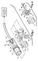
- FIG. 1is an enlarged fragmentary partially exploded perspective view of the distal end of the camera module which is used in conjunction with the PDA, specifically illustrating the arrangement of the image sensor with respect to the other elements of the camera module;
- FIG. 1 ais an enlarged exploded perspective view illustrating another configuration of the image sensor wherein video processing circuitry is placed behind and in longitudinal alignment with the image sensor;
- FIG. 2is a perspective view of the PDA incorporating the reduced area imaging device of this invention
- FIG. 3illustrates the PDA of FIG. 2 wherein the camera module is in the retracted position
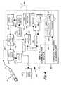
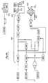
- FIG. 4is an overall schematic diagram of the functional electronic components which make up both the PDA and the reduced area imaging device wherein communications are achieved by wireless/cellular technology for video teleconferencing via the world wide web which is well-known as a global communications network;
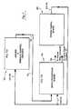
- FIG. 5is a schematic diagram illustrating an example communications network which can be used for data transfer of text, audio, and visual signals between the PDA and a personal computer which is in communication with the world wide web;
- FIG. 6 ais a perspective view of the PDA in combination with an externally attached wireless/cellular phone
- FIG. 6 bis another perspective view of the combination of FIG. 6 a illustrating the combination opened to expose the PDA;
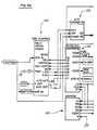
- FIG. 7is a more detailed schematic diagram of the functional electronic components which make up the imaging device.
- FIG. 7 ais an enlarged schematic diagram of a circuit board/planar structure which may include the array of pixels and the timing and control circuitry;
- FIG. 7 bis an enlarged schematic diagram of a video processing board/planar structure having placed thereon the processing circuitry which processes the pre-video signal generated by the array of pixels and which converts the pre-video signal to a post-video signal which may be accepted by an NTSC/PAL compatible video device;
- FIGS. 8 a - 8 eare schematic diagrams that illustrate an example of specific circuitry which may be used to make the video processing circuitry of the imaging device.
- a camera module 10which incorporates a reduced area imaging device 11 .
- the elements of the imaging device 11may all be found near one location, or the elements may be separated from one another and interconnected by the appropriate wired connections.
- the array of pixels making up the image sensorcaptures images and stores them in the form of electrical energy by conversion of light photons to electrons. This conversion takes place by the photo diodes in each pixel which communicate with one or more capacitors which store the electrons.
- the camera module 10includes an outer tube/sheath 14 which houses the components of the imaging device.
- the camera moduleis shown as being cylindrical in shape having a window 16 sealed at the distal end of the camera module.
- a retractable cable 12extends from the proximal end of the camera module 10 .
- a shielded cable 21is used to house the conductors which communicate with the imaging device 11 .
- the shielded cable 21is then housed within the retractable cable 12 .
- a lens group 18is positioned at the distal end of the camera module to enable an image to be appropriately conditioned prior to the image impinging upon the imaging device 11 .
- a focusing ring 20which enables the lens group 18 to be displaced distally or proximally to best focus an image on the imaging device 11 .
- a PDA 22which incorporates the camera module 10 .
- the PDA 22is a miniature hand-held computer incorporating a video system enabling video to be taken by the camera module, and viewed on the video view screen 26 , as well as enabling images to be stored and downloaded on a miniature computer disc (not shown) used with the PDA. Also discussed further below is the ability to transmit and receive audio and video signals.
- the PDA 22includes a housing 24 which hold the components of the PDA and the video system.
- Cable 12is housed within the housing 24 when in the retracted position.
- a spring biased spool (not shown) or some other known retracting deviceis mounted within the housing 24 enabling the cable 12 to be extended or retracted.
- a plurality of controlsare provided enabling the user to manipulate the functions of the PDA. These are shown as buttons 34 on the housing 24 .
- the video view screen 26is used for displaying video images taken by the camera module 10 , or for viewing incoming video signals received from a remote location.
- a command screen 28is provided which allows a user to select programs with a stylus (not shown).
- a video capture button 30is provided which allows a user to capture a still video image taken by the camera module 10 .
- a video store button 32is also provided which enables a captured video image to be stored within the digital memory of the PDA, as further discussed below.
- An opening or cavity 35is provided which allows the camera module 10 to be stored, along with cable 12 within the housing 24 . As shown in FIG. 3, the camera module 10 is in the stored or retracted position.
- the antenna 36allows for enhanced transmission and reception of incoming or transmitted/outgoing audio and video signals.
- a video select switch 37is provided enabling a user to view either video images taken by the camera module 10 , or for viewing incoming video images.
- the video view screen 26may be a liquid crystal display (LCD) type, or any other well-known display device of high resolution which has low power requirements, and has minimum size requirements as well.
- LCDliquid crystal display
- DISPLAYTECHmanufactures a miniature reflective display that consists of ferroelectric liquid crystal (FLC) applied to a CMOS integrated circuit.
- the reflective displayis a VGA display panel having low voltage digital operation, low power requirements, and full color operation.
- One of their specific productsincludes the LightCasterTM VGA Display Panel, Model LDP-0307-MV1. This is but one example of an LCD monitor which is available and usable within the invention herein described.
- a camera on/off switch 66is provided enabling the user to turn the video system on or off. Also shown in FIGS. 2 and 3 is a speaker 76 and a microphone 78 which are used for sending and receiving audio signals in the conventional manner as with a wireless/cellular telephone. A further description of speaker 76 and microphone 78 is found below.
- the imaging device 11includes an image sensor 40 .
- FIG. 1illustrates that the image sensor 40 can be a planar and square shaped member, or alternatively, planar and circular shaped to better fit within outer tube 14 .
- there is a power conductor 44 , a grounding conductor 46 , and an image signal conductor 48each of which are hardwired to the image sensor 40 .
- shielded cable 21may simply be a three conductor, 50 ohm type cable.
- Image sensor 40can be as small as 1 mm in its largest dimension. However, a more preferable size for most PDA applications would be between 4 mm to 8 mm in the image sensor's largest dimension (height or width).
- the image signal transmitted from the image sensor 40 through conductor 48is also herein referred to as a pre-video signal.
- video processing board 50receives the pre-video signal from image sensor 40 by means of conductor 48 , it is received by video processing board 50 , as shown in FIG. 7 .
- Video processing board 50then carries out all the necessary conditioning of the pre-video signal and places it in a form, also referred to herein as a video ready signal, so that it may be viewed directly on a remote video device such as a television or standard computer video monitor.
- the pre-video signalis further conditioned by a digital signal processor 72 , as further discussed below.
- the video signal produced by the video processing board 50can be viewed by an NTSC/PAL compatible video device (such as a television) which connects to the PDA through a remote jack.
- This video signal produced by board 50can be further defined as a post-video signal.
- FIG. 1illustrates an arrangement wherein the image sensor 40 is placed by itself adjacent the distal end of the camera module 10 .
- some or all of the video processing circuitrymay be placed in adjacent circuit boards directly behind the image sensor 40 .
- 1 aillustrates video processor board 50 aligned directly behind the image sensor 40 .
- a plurality of pin connectors 52can be used to interconnect image sensor 40 to video processor board 50 .
- pin connectors 52may be provided for structural support only, and/or to provide a means by which image signals are transmitted between image sensor 40 and board 50 .
- digital signal processor 72could also be placed behind image sensor 40 and behind video processing board 50 .
- the image sensor, and all supporting video processing circuitrycould be placed at the distal end of the camera module 10 .
- the conductor 49represents the conductor which may carry the post-video signal for direct connection with a remote video device 60 such as a television or computer monitor.
- a remote video device 60such as a television or computer monitor.
- placement of the digital signal processor 72 at the distal tip of the camera module behind the video processing board 50would also enable yet another conductor (not shown) to connect directly to the video monitor 26 for transmitting a video signal to the video monitor 26 .
- the area which is occupied by image sensor 40may be defined as the profile area of the imaging device and which determines its critical dimensions. If it is desired to place video processing circuitry adjacent the image sensor 40 at the distal end of the camera module 10 , such circuitry must be able to be placed on one or more circuit boards which are longitudinally aligned with image sensor 40 along longitudinal axis XX. If it is not important to limit the size of the profile area, then any circuitry placed behind image sensor 40 can be aligned in an offset manner, or may simply be larger than the profile area of image sensor 40 . In the configuration shown in FIG. 1 a, it is desirable that elements 40 and 50 be approximately the same size so that they may uniformly fit within the distal end of outer tube 14 .
- the PDA 22 of this inventionincludes functionality normally found in multiple devices. Specifically, the PDA 22 includes the computing capability of a PDA, a mobile/wireless phone, communication means for connection to a computer network such as the worldwide web, and a video system.
- the PDA 22may be separated into two major groups, namely, a video and communication system 61 , and a computer processing and memory unit 82 . Both of these are discussed in further detail below.
- a conventional lithium ion battery 62is provided which communicates with power supply board 64 .
- Power supply board 64conditions various power outputs to the components of the device, to include power to the video components.
- the power to the imaging devicemay simply be direct current of between about 1.5 to 12 volts, depending upon the power requirements of the imaging device.
- a camera on/off switch 66must be set to the “on” position in order to activate the camera module 10 .
- the video processor board 50then transfers power to supplies the camera module 10 , and also receives the analog pre-video signal back from the camera module, as further discussed below.
- the video signalAfter processing of the pre-video signal at the video processor board 50 , the video signal is video ready, meaning that it may then be directly viewed on a remote compatible video device 60 , such as a television or computer monitor.
- a video port 54can be provided on the housing 24 enabling a user to take a standard video jack (not shown) and interconnect the PDA with the video port of the remote video device.
- the video format for such remote video devicesincludes NTSC/PAL and VGA; thus, the video signal processed by video processor board 50 creates the video ready signals for use with these remote video devices.
- the pre-video signalis further processed into a digital format within video processor board 50 , preferably an 8 bit component video signal format that is commonly referred to as “YUV 4:2:2.”
- This video formateasily lends itself to video compression.
- This 8 bit digital video signalis then sent to the digital signal processor 72 which performs two functions relevant to the video signal.
- the digital signal processor 72further converts the signal into a format that is compatible with the driver circuitry of the video monitor 26 .
- the digital signal processor 72compresses the YV signal using a common video compression format, preferably JPEG.
- the JPEG encoded video signalis then mixed with the audio signal created by microphone 78 and amplifier 74 , and the resulting high frequency carrier signal may then be passed onto the transceiver/amplifier section 70 for transmission.
- the transceiver/amplifier 70is intended for communication with well-known wide area wireless communication networks. It is also contemplated within the spirit and scope of this invention that the PDA 22 be capable of communication with computer networks to include the worldwide web. Accordingly, the invention is well adapted for conducting video teleconferencing which is normally conducted with desktop computers and supplemental video equipment.
- the transceiver/amplifier sectionalso modulates the carrier signal prior to transmission.
- the video signal from digital signal processor 72is either sent to the monitor 26 , or is sent to the transceiver/amplifier section 70 for transmission.
- the antenna 36is used for enhancement of reception and transmission of transmitted and received carrier signals.
- the transceiver/amplifier section 70also serves as a receiver which receives an incoming carrier signal. This incoming signal is then demodulated within section 70 , the video and audio components of the incoming signal are separated, and then these separated signals are then sent to the digital signal processor 72 which performs video decompression. Then, the decompressed video signal is sent to the monitor 26 for viewing (if the video switch 37 is placed in that selected mode). The decompressed audio signal is sent to the amplifier 74 , and then to the speaker 76 .
- FIG. 4shows the transceiver/amplifier section 70 as being a cellular digital packet data system (CDPD) type transceiver.
- CDPDdigital packet data system
- This particular transceiver/amplifier 70could be the same as that disclosed in the U.S. Pat. No. 6,034,621.
- a cellular digital packet systemis a wireless standard providing two-way, 19.2 kbps packet data transmission over existing cellular telephone channels.
- the video switch 37may simply be a momentary, spring loaded, push button-type switch.
- incoming videowhich is received via the antenna 36 , is processed as discussed above in the transceiver/amplifier section 70 and digital signal processor 72 , and then sent to the monitor 26 .
- the video switch 37is depressed and held, the video signal produced from the camera module 10 is processed as discussed above, and ultimately sent to the monitor 26 for viewing by the user.
- An operatorcan cycle the switch 37 between the two positions in order to selectively choose whether to view incoming or outgoing video.
- FIG. 5illustrates a communications network which can be used by the invention.
- a communications network of this typeis disclosed in the U.S. Pat. No. 6,034,621, and is discussed specifically therein at FIGS. 3 and 4 of that patent.
- FIG. 5illustrates a CDPD base station 182 with a remote computer 188 utilizing a direct connection to the CDPD base station 182 via a modem 186 with a dial-up connection to the public switch telephone network (PSTN) 184 .
- PSTNpublic switch telephone network
- the CDPD base station 182includes an antenna 181 .
- the remote computer 188can be a personal computer, a server, or any other well-known stand-alone computer.
- the computer processing and memory unit 82which allows the PDA 22 to achieve basic word processing, etc., includes a microprocessor 83 , RAM 84 , ROM 86 , and digital storage 88 .
- Digital storage 88is provided for storing the formatted images taken by the camera module 10 .
- the RAM 84 , microprocessor 83 , and ROM 86are conventional or standard components as found in existing PDAs.
- An input/output bus 89is provided which allows video signals to be stored or otherwise manipulated within the computer processing and memory unit 82 . Accordingly, video taken by camera module 10 can be downloaded to digital storage 88 . Also, existing image data stored in digital storage 88 could be viewed on video monitor 26 .
- FIGS. 6 a and 6 billustrate another combination of the invention wherein the PDA 22 is simply combined with an externally mounted cellular telephone 190 .
- the cellular phone 190is a commercially available cellular/wireless telephone. As shown, the telephone includes the standard keypad 194 , visual display 196 , and antennae 198 .
- the phone 190is secured to the PDA 22 as by mounting means 192 , which is shown in the preferred embodiment as a piano-type hinge.
- mounting means 192which is shown in the preferred embodiment as a piano-type hinge.
- the PDAis altered very simply by providing means by which a cellular telephone can be attached to the PDA. This enables the user to hold both the PDA and cellular telephone in one hand while manipulating the PDA or phone 190 as desired with the other hand.
- All of the telephone circuitry for phone 190is housed within the phone itself, and there is no circuitry within the PDA which is used within the phone 190 .
- the actual size of the phone 190is smaller than the PDA 22 .
- the phone 190is housed in a larger housing 200 which essentially matches the dimensions of housing 24 .
- a peripheral flangecould be provided on the inner surface of housing 200 which comes into contact with housing 24 in the closed position of FIG. 6 a which would prevent inadvertent activation of the control buttons on the PDA 22 .
- FIG. 7is a schematic diagram illustrating one way in which the imaging device 11 may be constructed.
- the image sensor 40may include the timing and control circuits on the same planar structure. Power is supplied to image sensor 40 by power supply board 64 .
- the connection between image sensor 40 and board 64may simply be a cable having two conductors therein, one for ground and another for transmitting the desired voltage. These are illustrated as conductors 44 and 46 .
- the output from image sensor 40 in the form of the pre-video signalis input to video processor board 50 by means of the conductor 48 .
- conductor 48may simply be a 50 ohm conductor.
- Power and groundalso are supplied to video processing board 50 by conductors 44 and 46 from power supply board 52 .
- the output signal from the video processor board 50is in the form of the post-video signal and which may be carried by conductor 49 which can also be a 50 ohm conductor.
- FIG. 7illustrates the image sensor and the timing and control circuits being placed on the same circuit board or planar structure, it is possible to separate the timing and control circuits from the pixel array and place the timing and control circuits onto video processing board 50 .
- the advantage in placing the timing and control circuits on the same planar structure as the image sensoris that only three connections are required between image sensor 40 and the rest of the imaging device, namely, conductors 44 , 46 and 48 . Additionally, placing the timing and control circuits on the same planar structure with the pixel array results in the pre-video signal having less noise. Furthermore, the addition of the timing and control circuits to the same planar structure carrying the image sensor only adds a negligible amount of size to one dimension of the planar structure.
- the pixel arrayis to be the only element on the planar structure, then additional connections must be made between the planar structure and the video processing board 50 in order to transmit the clock signals and other control signals to the pixel array.
- additional connectionsFor example, a ribbon-type cable (not shown) or a plurality of 50 ohm coaxial cables (not shown) must be used in order to control the downloading of information from the pixel array.
- a ribbon-type cable(not shown) or a plurality of 50 ohm coaxial cables (not shown) must be used in order to control the downloading of information from the pixel array.
- Each of these additional connectionswould be hard wired between the boards.
- FIG. 7 ais a more detailed schematic diagram of image sensor 40 which contains an array of pixels 90 and the timing and control circuits 92 .
- a pixel array 90which can be used within the invention is similar to that which is disclosed in U.S. Pat. No. 5,471,515 to Fossum, et al., said patent being incorporated by reference herein. More specifically, FIG. 3 of Fossum, et al. illustrates the circuitry which makes up each pixel in the array of pixels 90 .
- the array of pixels 90 as described in Fossum, et al.is an active pixel group with intra-pixel charged transfer.
- the image sensor made by the array of pixelsis formed as a monolithic complementary metal oxide semiconductor (CMOS) integrated circuit which may be manufactured in an industry standard complementary metal oxide semiconductor process.
- the integrated circuitincludes a focal plane array of pixel cells, each one of the cells including a photo gate overlying the substrate for accumulating the photo generated charges.
- CMOScomplementary metal oxide semiconductor
- an imageimpinges upon the array of pixels, the image being in the form of photons which strike the photo diodes in the array of pixels.
- the photo diodes or photo detectorsconvert the photons into electrical energy or electrons which are stored in capacitors found in each pixel circuit.
- Each pixel circuithas its own amplifier which is controlled by the timing and control circuitry discussed below.
- the information or electrons stored in the capacitorsis unloaded in the desired sequence and at a desired frequency, and then sent to the video processing board 50 for further processing.
- the array of pixels 90 of the image sensor 40may be placed alone on a first plane, or the timing and control circuitry 92 may be placed with the array of pixels 90 on the first plane. If the timing and control circuitry 92 is not placed with the array of pixels 90 on the first plane, the timing and control circuitry 92 may be placed by itself on a second plane, or the timing and control circuitry 92 may be placed on a second plane with some or all of the processing circuitry from video processing board 50 .
- the video processing board 50itself may be placed on one or more planes on corresponding circuit boards containing video processing circuitry.
- FIG. 1 aillustrates a single video processor board 50 located directly behind image sensor 40 ; however, it shall be understood that additional circuit boards containing additional circuitry may be placed behind the image sensor 40 and behind the video processing board 50 . Some or all of the video processing circuitry may be placed within the camera module 10 near the distal end thereof adjacent the image sensor 40 . Video processing circuitry which is not placed within the distal end of the camera module 10 may be placed within the housing 24 of the PDA. If video processing circuitry is placed near the distal end of the camera module 10 , it is preferable to arrange the video processing circuitry in a stacked relationship behind the image sensor 40 . Additionally, it is preferable to place the processing circuitry in a parallel arrangement with respect to image sensor 40 and to center such video processing circuitry along axis X—X in order to minimize the size of camera module 10 .
- the timing and control circuits 92are used to control the release of the image information or image signal stored in the pixel array.
- the pixelsare arranged in a plurality of rows and columns.
- the image information from each of the pixelsis first consolidated in a row by row fashion, and is then downloaded from one or more columns which contain the consolidated information from the rows.
- the control of information consolidated from the rowsis achieved by latches 94 , counter 96 , and decoder 98 .
- the operation of the latches, counter and decoderis similar to the operation of similar control circuitry found in other imaging devices.
- a latchis a means of controlling the flow of electrons from each individual addressed pixel in the array of pixels.
- a latch 94When a latch 94 is enabled, it will allow the transfer of electrons to the decoder 98 .
- the counter 96is programmed to count a discrete amount of information based upon a clock input from the timing and control circuits 92 .
- the image informationis allowed to pass through the latches 94 and be sent to the decoder 98 which places the consolidated information in a serial format.
- the row driver 100accounts for the serial information from each row and enables each row to be downloaded by the column or columns.
- the latches 94will initially allow the information stored in each pixel to be accessed.
- the counter 96then controls the amount of information flow based upon a desired time sequence. Once the counter has reached its set point, the decoder 98 then knows to take the information and place it in the serial format. The whole process is repeated, based upon the timing sequence that is programmed.
- the row driver 100When the row driver 100 has accounted for each of the rows, the row driver reads out each of the rows at the desired video rate.
- the information released from the column or columnsis also controlled by a series of latches 102 , a counter 104 and a decoder 106 .
- the column informationis also placed in a serial format which may then be sent to the video processing board 50 .
- This serial format of column informationis the pre-video signal carried by conductor 48 .
- the column signal conditioner 108places the column serial information in a manageable format in the form of desired voltage levels. In other words, the column signal conditioner 108 only accepts desired voltages from the downloaded column(s).
- the clock input to the timing and control circuits 92may simply be a quartz crystal timer. This clock input is divided into many other frequencies for use by the various counters.
- the run input to the timing and control circuit 92may simply be an on/off control.
- the default inputcan allow one to input the pre-video signal to a video processor board which may run at a frequency of other than 30 hertz.
- the data inputcontrols functions such as zoom. At least for a CMOS type active pixel array which can be accessed in a random manner, features such as zoom are easily manipulated by addressing only those pixels which locate a desired area of interest by the user.
- image sensor 40Once image sensor 40 has created the pre-video signal, it is sent to the video processing board 50 for further processing.
- the pre-video signalis passed through a series of filters.
- One common filter arrangementmay include two low pass filters 114 and 116 , and a band pass filter 112 .
- the band pass filteronly passes low frequency components of the signal. Once these low frequency components pass, they are then sent to detector 120 and white balance circuit 124 , the white balance circuit distinguishing between the colors of red and blue.
- the white balance circuithelps the imaging device set its normal, which is white.
- the portion of the signal passing through low pass filter 114then travels through gain control 118 which reduces the magnitude or amplitude of this portion to a manageable level.
- the output from gain control 118is then fed back to the white balance circuit 124 .
- the portion of the signal traveling through filter 116is placed through the processor 122 .
- the portion of the signal carrying the luminance or non-chromais separated and sent to the Y chroma mixer 132 . Any chroma portion of the signal is held in processor 122 .
- this chroma portion of the signalis sent to a delay line 126 where the signal is then further reduced by switch 128 .
- the output of switch 128is sent through a balanced modulator 130 and also to the Y chroma mixer 132 where the processed chroma portion of the signal is mixed with the processed non-chroma portion.
- the output from the Y chroma mixer 132is sent to the NTSC/PAL encoder 134 , commonly known in the art as a “composite” encoder.
- the composite frequenciesare added to the signal leaving the Y chroma mixer 132 in encoder 134 to produce the post-video signal which may be accepted by a television.
- the signal from Y chroma mixer 132is sent to the digital signal processor 72 so that images can be viewed on monitor 26 .
- the processor 72can also provide additional digital enhancements. Specifically, digital enhancement can sharpen or otherwise clarify the edges of an image viewed on a video screen which might normally be somewhat distorted. Additionally, selected background or foreground images may be removed thus only leaving the desired group of images.
- the digital signal processor 72can include other circuitry which may further condition the signal received from board 50 so that it may be viewed in a desired format other than NTSC/PAL.
- One common encoder which can be usedwould be an RGB encoder.
- An RGB encoderseparates the signal into the three primary colors (red, green and blue).
- a SVHS encoder (super video home system) encodercould also be added to processor 72 . This type of encoder splits or separates the luminance portion of the signal and the chroma portion of the signal. Some observers believe that a more clear signal is input to the video device by such a separation, which in turn results in a more clear video image viewed on the video device.
- Another example of an encoder which could be added to processor 72includes a VGA compatible encoder, which enables the video signal to be viewed on a standard VGA monitor which is common to many computer monitors.
- FIGS. 8 a - 8 eillustrate in more detail one example of circuitry which may be used in the video processing board 50 in order to produce a post-video signal which may be directly accepted by a NTSC/PAL compatible video device such as a television.
- the circuitry disclosed in FIGS. 8 a - 8 eis very similar to circuitry which is found in a miniature quarter-inch Panasonic camera, Model KS-162. It will be understood by those skilled in the art that the particular arrangement of elements found in FIGS. 8 a - 8 e are only exemplary of the type of video processing circuitry which may be incorporated in order to take the pre-video signal and condition it to be received by a desired video device.
- 5 volt poweris provided along with a ground by conductors 44 and 46 to board 50 .
- the pre-video signal carried by conductor 48is buffered at buffer 137 and then is transferred to amplifying group 138 .
- Amplifying group 138amplifies the signal to a usable level as well as achieving impedance matching for the remaining circuitry.
- the next major elementis the automatic gain control 140 shown in FIG. 8 b.
- Automatic gain control 140automatically controls the signal from amplifying group 138 to an acceptable level and also adds other characteristics to the signal as discussed below. More specifically, automatic gain control 140 conditions the signal based upon inputs from a 12 channel digital to analog converter 141 .
- Converter 141retrieves stored information from EEPROM (electrically erasable programmable read only memory) 143 .
- EEPROM 143is a non-volatile memory element which may store user information, for example, settings for color, tint, balance and the like.
- automatic gain control 140changes the texture or visual characteristics based upon user inputs. Housing 24 could also include buttons for controlling the image viewed on monitor 26 such as a gain control 140 .
- the signal leaving the automatic gain control 140is an analog signal until being converted by analog to digital converter 142 .
- Digital signal processor 144 of FIG. 8 cfurther processes the converted signal into a serial type digital signal.
- One function of the microprocessor 146is to control the manner in which digital signal processor 144 sorts the digital signals emanating from converter 142 .
- Microprocessor 146also controls analog to digital converter 142 in terms of when it is activated, when it accepts data, when to release data, and the rate at which data should be released.
- Microprocessor 146may also control other functions of the imaging device such as white balance.
- the microprocessor 146may selectively receive the information stored in the EEPROM 143 and carry out its various commands to further control the other elements within the circuitry.
- digital encoder 148After the signal is processed by digital signal processor 144 , the signal is sent to digital encoder 148 illustrated in FIG. 8 d. Some of the more important functions of digital encoder 148 are to encode the digital signal with synchronization, modulated chroma, blanking, horizontal drive, and the other components necessary so that the signal may be placed in a condition for reception by a video device such as a television monitor. As also illustrated in FIG. 8 d, once the signal has passed through digital encoder 148 , the signal is reconverted into an analog signal through digital to analog converter 150 .
- This reconverted analog signalis then buffered at buffers 151 and then sent to amplifier group 152 of FIG. 8 e which amplifies the signal so that it is readily accepted by a desired video device.
- amplifier group 152 of FIG. 8 ewhich amplifies the signal so that it is readily accepted by a desired video device.
- one SVHS outletis provided at 160
- two composite or NTSC outletsare provided at 162 and 164 , respectively.
- an entire imaging devicemay be incorporated within the distal tip of the camera module, or may have some elements of the imaging device being placed in the housing of the PDA. Based upon the type of image sensor used, the profile area of the imaging device may be made small enough to be placed into a camera module which has a very small diameter.
Landscapes
- Engineering & Computer Science (AREA)
- Health & Medical Sciences (AREA)
- Life Sciences & Earth Sciences (AREA)
- Computer Hardware Design (AREA)
- Physics & Mathematics (AREA)
- Theoretical Computer Science (AREA)
- Surgery (AREA)
- General Engineering & Computer Science (AREA)
- General Physics & Mathematics (AREA)
- Human Computer Interaction (AREA)
- Nuclear Medicine, Radiotherapy & Molecular Imaging (AREA)
- General Health & Medical Sciences (AREA)
- Veterinary Medicine (AREA)
- Public Health (AREA)
- Animal Behavior & Ethology (AREA)
- Biophysics (AREA)
- Molecular Biology (AREA)
- Optics & Photonics (AREA)
- Pathology (AREA)
- Radiology & Medical Imaging (AREA)
- Medical Informatics (AREA)
- Biomedical Technology (AREA)
- Heart & Thoracic Surgery (AREA)
- Multimedia (AREA)
- Signal Processing (AREA)
- Microelectronics & Electronic Packaging (AREA)
- Mathematical Physics (AREA)
- Condensed Matter Physics & Semiconductors (AREA)
- Power Engineering (AREA)
- Computer Networks & Wireless Communication (AREA)
- Studio Devices (AREA)
- Transforming Light Signals Into Electric Signals (AREA)
Abstract
Description
Claims (75)
Priority Applications (8)
| Application Number | Priority Date | Filing Date | Title |
|---|---|---|---|
| US09/638,976US6424369B1 (en) | 1997-10-06 | 2000-08-15 | Hand-held computers incorporating reduced area imaging devices |
| JP2002520552AJP2004536467A (en) | 2000-02-01 | 2001-06-20 | Handheld computer with small area image forming device |
| EP01948575AEP1310090A1 (en) | 2000-02-01 | 2001-06-20 | Hand-held computers incorporating reduced area imaging devices |
| AU2001270042AAU2001270042A1 (en) | 2000-02-01 | 2001-06-20 | Hand-held computers incorporating reduced area imaging devices |
| PCT/US2001/019855WO2002015567A1 (en) | 2000-02-01 | 2001-06-20 | Hand-held computers incorporating reduced area imaging devices |
| US09/935,993US6982742B2 (en) | 1997-10-06 | 2001-08-23 | Hand-held computers incorporating reduced area imaging devices |
| US10/171,906US20020163578A1 (en) | 1997-10-06 | 2002-06-13 | Hand-held computers incorporating reduced area imaging devices |
| JP2007008436AJP4312800B2 (en) | 2000-02-01 | 2007-01-17 | Handheld computer with small area image forming device |
Applications Claiming Priority (4)
| Application Number | Priority Date | Filing Date | Title |
|---|---|---|---|
| US08/944,322US5929901A (en) | 1997-10-06 | 1997-10-06 | Reduced area imaging devices incorporated within surgical instruments |
| US09/175,685US6043839A (en) | 1997-10-06 | 1998-10-20 | Reduced area imaging devices |
| US09/496,312US6275255B1 (en) | 1997-10-06 | 2000-02-01 | Reduced area imaging devices |
| US09/638,976US6424369B1 (en) | 1997-10-06 | 2000-08-15 | Hand-held computers incorporating reduced area imaging devices |
Related Parent Applications (1)
| Application Number | Title | Priority Date | Filing Date |
|---|---|---|---|
| US09/496,312Continuation-In-PartUS6275255B1 (en) | 1997-09-11 | 2000-02-01 | Reduced area imaging devices |
Related Child Applications (2)
| Application Number | Title | Priority Date | Filing Date |
|---|---|---|---|
| US09/935,993Continuation-In-PartUS6982742B2 (en) | 1997-10-06 | 2001-08-23 | Hand-held computers incorporating reduced area imaging devices |
| US10/171,906ContinuationUS20020163578A1 (en) | 1997-10-06 | 2002-06-13 | Hand-held computers incorporating reduced area imaging devices |
Publications (1)
| Publication Number | Publication Date |
|---|---|
| US6424369B1true US6424369B1 (en) | 2002-07-23 |
Family
ID=24562229
Family Applications (2)
| Application Number | Title | Priority Date | Filing Date |
|---|---|---|---|
| US09/638,976Expired - LifetimeUS6424369B1 (en) | 1997-10-06 | 2000-08-15 | Hand-held computers incorporating reduced area imaging devices |
| US10/171,906AbandonedUS20020163578A1 (en) | 1997-10-06 | 2002-06-13 | Hand-held computers incorporating reduced area imaging devices |
Family Applications After (1)
| Application Number | Title | Priority Date | Filing Date |
|---|---|---|---|
| US10/171,906AbandonedUS20020163578A1 (en) | 1997-10-06 | 2002-06-13 | Hand-held computers incorporating reduced area imaging devices |
Country Status (5)
| Country | Link |
|---|---|
| US (2) | US6424369B1 (en) |
| EP (1) | EP1310090A1 (en) |
| JP (2) | JP2004536467A (en) |
| AU (1) | AU2001270042A1 (en) |
| WO (1) | WO2002015567A1 (en) |
Cited By (118)
| Publication number | Priority date | Publication date | Assignee | Title |
|---|---|---|---|---|
| US20020030844A1 (en)* | 2000-02-02 | 2002-03-14 | Tuli Raja Singh | Portable high speed internet access device |
| US20020044225A1 (en)* | 2000-01-14 | 2002-04-18 | Rakib Selim Shlomo | Remote control for wireless control of system and displaying of compressed video on a display on the remote |
| US20020065111A1 (en)* | 2000-11-30 | 2002-05-30 | Shuji Otsuka | Portable telephone device |
| US20020063799A1 (en)* | 2000-10-26 | 2002-05-30 | Ortiz Luis M. | Providing multiple perspectives of a venue activity to electronic wireless hand held devices |
| US20020065662A1 (en)* | 2000-07-11 | 2002-05-30 | Sherman William F. | Voice recognition peripheral device |
| US20020065902A1 (en)* | 2000-09-05 | 2002-05-30 | Janik Craig M. | Webpad and method for using the same |
| US20020085098A1 (en)* | 2001-01-04 | 2002-07-04 | Takako Miyazaki | System and method for efficiently capturing and managing electronic information |
| US20020123687A1 (en)* | 2000-12-21 | 2002-09-05 | Rainer Birkenbach | Cable-free medical detection and treatment system |
| US20020152476A1 (en)* | 1999-05-28 | 2002-10-17 | Anderson Tazwell L. | Audio/video programming and charging system and method |
| US20030002749A1 (en)* | 2001-06-28 | 2003-01-02 | Nokia Corporation, Espoo Finland | Method and apparatus for image improvement |
| US20030034987A1 (en)* | 2001-08-17 | 2003-02-20 | William Webb | Handheld computer having moveable segments that can be adjusted to affect a size of the handheld computer |
| US20030041106A1 (en)* | 2000-10-03 | 2003-02-27 | Raja Tuli | Portable high speed internet access device priority protocol |
| US20030045955A1 (en)* | 2000-09-01 | 2003-03-06 | Janik Craig M. | Audio converter device and method for using the same |
| US20030064747A1 (en)* | 2001-10-02 | 2003-04-03 | Simmons Laura E. | Integrated circuit architecture for programmable wireless device |
| US20030112354A1 (en)* | 2001-12-13 | 2003-06-19 | Ortiz Luis M. | Wireless transmission of in-play camera views to hand held devices |
| US20030123538A1 (en)* | 2001-12-21 | 2003-07-03 | Michael Krause | Video recording and encoding in devices with limited processing capabilities |
| US20030137493A1 (en)* | 2002-01-18 | 2003-07-24 | Wei-Pin Chuang | Personal digital assistant with a replaceable peripheral module at one of its corners |
| US20030154334A1 (en)* | 2002-02-08 | 2003-08-14 | Ko-Chien Chuang | Personal digital assistant system |
| US20030197725A1 (en)* | 2000-02-02 | 2003-10-23 | Raja Tuli | Portable high speed internet device integrating cellular telephone and palm top computer |
| US20030222846A1 (en)* | 2002-05-31 | 2003-12-04 | Huy Nguyen | Multi-functional handheld device having moveable segments |
| US20030222847A1 (en)* | 2002-05-31 | 2003-12-04 | Huy Nguyen | Handheld computer having an adjustable length for selectively exposing a surface component |
| US20040036358A1 (en)* | 2002-08-20 | 2004-02-26 | Sony Corporation | Electronic device with attachment and switching between batteries therefor |
| US20040056887A1 (en)* | 2002-09-24 | 2004-03-25 | Lg Electronics Inc. | System and method for multiplexing media information over a network using reduced communications resources and prior knowledge/experience of a called or calling party |
| US20040160637A1 (en)* | 2000-02-02 | 2004-08-19 | Tuli Raja Singh | Portable high speed internet access device |
| US20040177284A1 (en)* | 2003-03-07 | 2004-09-09 | Vance Chin | Personal computing device having single-cell battery |
| US20040184664A1 (en)* | 2000-02-02 | 2004-09-23 | Tuli Raja Singh | Portable high speed internet access device |
| US20040198458A1 (en)* | 2002-02-18 | 2004-10-07 | Nec Corporation | Portable information terminal |
| US20040204144A1 (en)* | 2002-04-22 | 2004-10-14 | Chae-Whan Lim | Device and method for transmitting display data in a mobile communication terminal with camera |
| US20040253945A1 (en)* | 1999-03-04 | 2004-12-16 | Janik Craig M. | System for providing content, management, and interactivity for thin client devices |
| US20050005298A1 (en)* | 2000-10-27 | 2005-01-06 | Audiovox Corporation | Vehicle console capable of wireless reception and transmission of audio and video data |
| US6842777B1 (en) | 2000-10-03 | 2005-01-11 | Raja Singh Tuli | Methods and apparatuses for simultaneous access by multiple remote devices |
| US6874009B1 (en) | 2000-02-16 | 2005-03-29 | Raja Tuli | Portable high speed internet device with user fees |
| US20050085690A1 (en)* | 2003-10-15 | 2005-04-21 | Der-Yang Tien | Endoscope apparatus |
| US20050088401A1 (en)* | 2001-11-09 | 2005-04-28 | Daly Scott J. | Liquid crystal display backlight with level change |
| US20050117186A1 (en)* | 2003-11-21 | 2005-06-02 | Baoxin Li | Liquid crystal display with adaptive color |
| US6915327B1 (en) | 2000-10-30 | 2005-07-05 | Raja Singh Tuli | Portable high speed communication device peripheral connectivity |
| US20050146600A1 (en)* | 2003-12-29 | 2005-07-07 | Jan Chipchase | Method and apparatus for improved handset multi-tasking, including pattern recognition and augmentation of camera images |
| US20050170686A1 (en)* | 2004-02-02 | 2005-08-04 | Thorland Miles K. | Retractable cable system for personal computers |
| US6941382B1 (en) | 2000-02-07 | 2005-09-06 | Raja Tuli | Portable high speed internet or desktop device |
| US6943774B2 (en)* | 2001-04-02 | 2005-09-13 | Matsushita Electric Industrial Co., Ltd. | Portable communication terminal, information display device, control input device and control input method |
| US20050210101A1 (en)* | 1999-03-04 | 2005-09-22 | Universal Electronics Inc. | System and method for providing content, management, and interactivity for client devices |
| US20060031550A1 (en)* | 2000-09-05 | 2006-02-09 | Universal Electronics Inc. | Webpad adapted to communicate using wide area and local area communication channels |
| US20060031549A1 (en)* | 2000-09-05 | 2006-02-09 | Universal Electronics Inc. | System and method for using a webpad to control a data stream |
| US20060094464A1 (en)* | 2004-11-01 | 2006-05-04 | Nec Corporation | Portable terminal apparatus with TV function and TV antenna with function as input pen |
| US20060105794A1 (en)* | 2004-11-12 | 2006-05-18 | International Business Machines Corporation | Push to view system for telephone communications |
| US20060104533A1 (en)* | 2004-11-16 | 2006-05-18 | Sharp Laboratories Of America, Inc. | High dynamic range images from low dynamic range images |
| US20060149813A1 (en)* | 1999-03-04 | 2006-07-06 | Simple Devices | System and method for providing content, management, and interactivity for client devices |
| US20060174297A1 (en)* | 1999-05-28 | 2006-08-03 | Anderson Tazwell L Jr | Electronic handheld audio/video receiver and listening/viewing device |
| US20060232546A1 (en)* | 2000-05-09 | 2006-10-19 | Semiconductor Energy Laboratory Co., Ltd. | User identity authentication system and user identity authentication method and mobile telephonic device |
| US7127271B1 (en) | 2001-10-18 | 2006-10-24 | Iwao Fujisaki | Communication device |
| US7149549B1 (en)* | 2000-10-26 | 2006-12-12 | Ortiz Luis M | Providing multiple perspectives for a venue activity through an electronic hand held device |
| US20070022445A1 (en)* | 2005-07-22 | 2007-01-25 | Marc Arseneau | System and Methods for Enhancing the Experience of Spectators Attending a Live Sporting Event, with User Interface Programming Capability |
| US7209113B2 (en)* | 2002-05-09 | 2007-04-24 | Gateway Inc. | Stylus pen expansion slot |
| US20070126924A1 (en)* | 2005-12-06 | 2007-06-07 | Hon Hai Precision Industry Co., Ltd. | Portable device with integrated camera |
| US20070238660A1 (en)* | 2006-03-31 | 2007-10-11 | Stephen Michielsen | Light activated antiviral materials and devices and methods for decontaminating virus infected environments |
| US7283788B1 (en)* | 2000-07-26 | 2007-10-16 | Posa John G | Remote microphone teleconferencing configurations |
| US7356570B1 (en) | 2000-08-29 | 2008-04-08 | Raja Tuli | Portable high speed communication device |
| US20080158678A1 (en)* | 2006-12-29 | 2008-07-03 | Cognex Corporation | Manually adjustable ruggedized focus mechanism |
| US20080287059A1 (en)* | 1999-03-08 | 2008-11-20 | Anderson Jr Tazwell L | Video/audio system and method enabling a user to select different views and sounds associated with an event |
| US7466992B1 (en) | 2001-10-18 | 2008-12-16 | Iwao Fujisaki | Communication device |
| US20090009605A1 (en)* | 2000-06-27 | 2009-01-08 | Ortiz Luis M | Providing multiple video perspectives of activities through a data network to a remote multimedia server for selective display by remote viewing audiences |
| US7493645B1 (en)* | 2000-10-27 | 2009-02-17 | Audiovox Corporation | Console with monitor and wireless receiver |
| US20090077203A1 (en)* | 1999-03-04 | 2009-03-19 | Ez4Media, Inc. | Clock with link to the internet |
| US7525528B2 (en) | 2004-11-16 | 2009-04-28 | Sharp Laboratories Of America, Inc. | Technique that preserves specular highlights |
| US7532192B2 (en) | 2004-05-04 | 2009-05-12 | Sharp Laboratories Of America, Inc. | Liquid crystal display with filtered black point |
| US20090128631A1 (en)* | 2000-10-26 | 2009-05-21 | Ortiz Luis M | Displaying broadcasts of multiple camera perspective recordings from live activities at entertainment venues on remote video monitors |
| US7593687B2 (en) | 2003-10-07 | 2009-09-22 | Immersion Entertainment, Llc | System and method for providing event spectators with audio/video signals pertaining to remote events |
| US7602369B2 (en) | 2004-05-04 | 2009-10-13 | Sharp Laboratories Of America, Inc. | Liquid crystal display with colored backlight |
| US7612757B2 (en) | 2004-05-04 | 2009-11-03 | Sharp Laboratories Of America, Inc. | Liquid crystal display with modulated black point |
| US7692667B2 (en) | 2001-08-17 | 2010-04-06 | Palm, Inc. | Handheld computer having moveable segments that are interactive with an integrated display |
| US20100110206A1 (en)* | 1998-06-22 | 2010-05-06 | Memorylink Corporation | Self-Contained Wireless Camera Drive, Wireless Camera System and Method |
| US7725073B2 (en) | 2002-10-07 | 2010-05-25 | Immersion Entertainment, Llc | System and method for providing event spectators with audio/video signals pertaining to remote events |
| US7777714B2 (en) | 2004-05-04 | 2010-08-17 | Sharp Laboratories Of America, Inc. | Liquid crystal display with adaptive width |
| US20100261961A1 (en)* | 2006-12-21 | 2010-10-14 | Intuitive Surgical Operations, Inc. | Hermetically sealed distal sensor endoscope |
| US7853094B2 (en) | 2006-01-24 | 2010-12-14 | Sharp Laboratories Of America, Inc. | Color enhancement technique using skin color detection |
| US7872631B2 (en) | 2004-05-04 | 2011-01-18 | Sharp Laboratories Of America, Inc. | Liquid crystal display with temporal black point |
| US20110037876A1 (en)* | 2009-08-13 | 2011-02-17 | Olive Medical Corp. | System, apparatus and methods for providing a single use imaging device for sterile environments |
| US7898519B2 (en) | 2005-02-17 | 2011-03-01 | Sharp Laboratories Of America, Inc. | Method for overdriving a backlit display |
| US7966636B2 (en) | 2001-05-22 | 2011-06-21 | Kangaroo Media, Inc. | Multi-video receiving method and apparatus |
| US20110238977A1 (en)* | 2010-03-25 | 2011-09-29 | Olive Medical Corporation | System and method for providing a single use imaging device for medical applications |
| US8042140B2 (en) | 2005-07-22 | 2011-10-18 | Kangaroo Media, Inc. | Buffering content on a handheld electronic device |
| US8050511B2 (en) | 2004-11-16 | 2011-11-01 | Sharp Laboratories Of America, Inc. | High dynamic range images from low dynamic range images |
| US8121401B2 (en) | 2006-01-24 | 2012-02-21 | Sharp Labortories of America, Inc. | Method for reducing enhancement of artifacts and noise in image color enhancement |
| US8150482B2 (en) | 2008-01-08 | 2012-04-03 | Hewlett-Packard Development Company, L.P. | Mobile computing device with moveable housing segments |
| US8176428B2 (en) | 2002-12-03 | 2012-05-08 | Datawind Net Access Corporation | Portable internet access device back page cache |
| US8200298B2 (en) | 2008-01-08 | 2012-06-12 | Hewlett-Packard Development Company, L.P. | Keypad housing configuration for a mobile computing device |
| US8233948B2 (en) | 2007-12-11 | 2012-07-31 | Hewlett-Packard Development Company, L.P. | Slider assembly for a housing of a mobile computing device |
| US8364295B2 (en) | 2000-10-12 | 2013-01-29 | Bose Corporation | Interactive sound reproducing |
| US8395577B2 (en) | 2004-05-04 | 2013-03-12 | Sharp Laboratories Of America, Inc. | Liquid crystal display with illumination control |
| US8583027B2 (en) | 2000-10-26 | 2013-11-12 | Front Row Technologies, Llc | Methods and systems for authorizing computing devices for receipt of venue-based data based on the location of a user |
| US20140257591A1 (en)* | 2013-03-11 | 2014-09-11 | Ice Computer, Inc. | Modular computer and thermal management |
| US8885034B2 (en) | 1997-10-06 | 2014-11-11 | Micro-Imaging Solutions Llc | Reduced area imaging device incorporated within endoscopic devices |
| US8941580B2 (en) | 2006-11-30 | 2015-01-27 | Sharp Laboratories Of America, Inc. | Liquid crystal display with area adaptive backlight |
| CN104323757A (en)* | 2014-11-13 | 2015-02-04 | 王卫东 | Endoscope with flash lamp and camera for portable intelligent equipment |
| US8952312B2 (en) | 2011-05-12 | 2015-02-10 | Olive Medical Corporation | Image sensor for endoscopic use |
| US9059809B2 (en) | 1998-02-23 | 2015-06-16 | Steven M. Koehler | System and method for listening to teams in a race event |
| US9300924B2 (en) | 1999-05-28 | 2016-03-29 | Immersion Entertainment, Llc. | Electronic handheld audio/video receiver and listening/viewing device |
| US9307893B2 (en) | 2011-12-29 | 2016-04-12 | Cook Medical Technologies Llc | Space-optimized visualization catheter with camera train holder in a catheter with off-centered lumens |
| US9370295B2 (en) | 2014-01-13 | 2016-06-21 | Trice Medical, Inc. | Fully integrated, disposable tissue visualization device |
| US9462234B2 (en) | 2012-07-26 | 2016-10-04 | DePuy Synthes Products, Inc. | Camera system with minimal area monolithic CMOS image sensor |
| US9646444B2 (en) | 2000-06-27 | 2017-05-09 | Mesa Digital, Llc | Electronic wireless hand held multimedia device |
| US9668643B2 (en) | 2011-12-29 | 2017-06-06 | Cook Medical Technologies Llc | Space-optimized visualization catheter with oblong shape |
| US10045686B2 (en) | 2008-11-12 | 2018-08-14 | Trice Medical, Inc. | Tissue visualization and modification device |
| US10244927B2 (en) | 2011-12-29 | 2019-04-02 | Cook Medical Technologies Llc | Space-optimized visualization catheter with camera train holder |
| US10342579B2 (en) | 2014-01-13 | 2019-07-09 | Trice Medical, Inc. | Fully integrated, disposable tissue visualization device |
| US10405886B2 (en) | 2015-08-11 | 2019-09-10 | Trice Medical, Inc. | Fully integrated, disposable tissue visualization device |
| US10517469B2 (en) | 2013-03-15 | 2019-12-31 | DePuy Synthes Products, Inc. | Image sensor synchronization without input clock and data transmission clock |
| US10750933B2 (en) | 2013-03-15 | 2020-08-25 | DePuy Synthes Products, Inc. | Minimize image sensor I/O and conductor counts in endoscope applications |
| US10983753B2 (en) | 2017-06-09 | 2021-04-20 | International Business Machines Corporation | Cognitive and interactive sensor based smart home solution |
| US11382496B2 (en) | 2006-12-21 | 2022-07-12 | Intuitive Surgical Operations, Inc. | Stereoscopic endoscope |
| US20220269311A1 (en)* | 2019-09-10 | 2022-08-25 | Intel Corporation | Laptop Computers with a Movable Accessory Housing |
| US11485286B2 (en) | 2006-02-07 | 2022-11-01 | Magna Electronics Inc. | Vehicle vision system with rear mounted camera |
| US11547446B2 (en) | 2014-01-13 | 2023-01-10 | Trice Medical, Inc. | Fully integrated, disposable tissue visualization device |
| US11548444B2 (en) | 2010-12-22 | 2023-01-10 | Magna Electronics Inc. | Vehicular multi-camera surround view system with video display |
| US11553125B2 (en) | 2018-09-13 | 2023-01-10 | Sony Corporation | Camera system and cables |
| US11577646B2 (en) | 2004-09-14 | 2023-02-14 | Magna Electronics Inc. | Vehicular trailer hitching assist system |
| US11622753B2 (en) | 2018-03-29 | 2023-04-11 | Trice Medical, Inc. | Fully integrated endoscope with biopsy capabilities and methods of use |
| US12035889B2 (en) | 2008-07-22 | 2024-07-16 | Trice Medical, Inc. | Tissue modification devices and methods of using the same |
Families Citing this family (7)
| Publication number | Priority date | Publication date | Assignee | Title |
|---|---|---|---|---|
| US7057635B1 (en)* | 2000-01-27 | 2006-06-06 | Atheros Communications, Inc. | High-speed RF link for a multi-user meeting |
| FR2841420B1 (en)* | 2002-06-25 | 2005-01-14 | France Telecom | AUDIOVISUAL SYSTEM FOR ESTABLISHING BIDIRECTIONAL COMMUNICATION BETWEEN A FIRST SCENE AND A SECOND SCENE |
| USD547346S1 (en) | 2004-03-09 | 2007-07-24 | V.I.O., Inc. | Camera |
| CN102957766A (en)* | 2011-08-18 | 2013-03-06 | 佛山正能光电有限公司 | Mobile device with detachable camera module |
| CN104188615A (en)* | 2014-08-29 | 2014-12-10 | 广州耀远实业有限公司 | Mobile endoscope image system and remote endoscope system |
| US10659697B2 (en)* | 2016-02-21 | 2020-05-19 | Jinrong Yang | Portable electronic device with retractable antenna rod for a camera |
| US12268359B2 (en)* | 2023-03-13 | 2025-04-08 | Endoluxe Inc. | Handheld unit for endoscopy, laparoscopy, and other scopic procedures and methods of manufacture and use thereof |
Citations (42)
| Publication number | Priority date | Publication date | Assignee | Title |
|---|---|---|---|---|
| US4491865A (en) | 1982-09-29 | 1985-01-01 | Welch Allyn, Inc. | Image sensor assembly |
| US4745471A (en) | 1986-05-13 | 1988-05-17 | Olympus Optical Co., Ltd. | Solid-state imaging apparatus and endoscope |
| US4786965A (en) | 1986-09-04 | 1988-11-22 | Olympus Optical Co., Ltd. | Eletronic endoscope with an imaging device having side bonding pads |
| US4814648A (en) | 1987-09-24 | 1989-03-21 | Texas Instruments Incorporated | Low 1/f noise amplifier for CCD imagers |
| US4854302A (en) | 1987-11-12 | 1989-08-08 | Welch Allyn, Inc. | Video equipped endoscope with needle probe |
| US4869246A (en) | 1987-12-11 | 1989-09-26 | Adair Edwin Lloyd | Method for controllably embolyzing blood vessels |
| US4928300A (en) | 1988-06-27 | 1990-05-22 | Mitsubishi Denki Kabushiki Kaisha | Videophone with detachable TV camera |
| US4942473A (en) | 1987-07-16 | 1990-07-17 | Techninon Research & Development Foundation | Intelligent scan image sensor |
| USRE33854E (en) | 1989-02-03 | 1992-03-24 | sterilizable sheathpe with .[.heat.]. | |
| US5116317A (en) | 1988-06-16 | 1992-05-26 | Optimed Technologies, Inc. | Angioplasty catheter with integral fiber optic assembly |
| EP0492349A1 (en) | 1990-12-28 | 1992-07-01 | Matsushita Electric Industrial Co., Ltd. | Camera head for solid-state image pickup device and method of producing same |
| US5162913A (en) | 1990-02-26 | 1992-11-10 | Medical Concepts, Inc. | Apparatus for modulating the output of a ccd camera |
| US5220198A (en) | 1990-08-27 | 1993-06-15 | Olympus Optical Co., Ltd. | Solid state imaging apparatus in which a solid state imaging device chip and substrate are face-bonded with each other |
| US5251613A (en) | 1991-05-06 | 1993-10-12 | Adair Edwin Lloyd | Method of cervical videoscope with detachable camera |
| US5381784A (en) | 1992-09-30 | 1995-01-17 | Adair; Edwin L. | Stereoscopic endoscope |
| US5402768A (en) | 1992-09-01 | 1995-04-04 | Adair; Edwin L. | Endoscope with reusable core and disposable sheath with passageways |
| US5453785A (en) | 1992-04-30 | 1995-09-26 | Jos. Schneider Optische Werke Kreuznach Gmbh & Co. Kg | Measurement camera with fixed geometry and rigid length support |
| US5471515A (en) | 1994-01-28 | 1995-11-28 | California Institute Of Technology | Active pixel sensor with intra-pixel charge transfer |
| US5489256A (en) | 1992-09-01 | 1996-02-06 | Adair; Edwin L. | Sterilizable endoscope with separable disposable tube assembly |
| US5605531A (en) | 1994-04-08 | 1997-02-25 | Tilane Corporation | Apparatus for use with endoscopy and fluoroscopy for automatic switching between video modes |
| US5630783A (en) | 1995-08-11 | 1997-05-20 | Steinberg; Jeffrey | Portable cystoscope |
| US5630782A (en) | 1992-09-01 | 1997-05-20 | Adair; Edwin L. | Sterilizable endoscope with separable auxiliary assembly |
| WO1997026744A2 (en) | 1996-01-17 | 1997-07-24 | Garry Douglas Robb | Multifunctional portable telephone |
| US5682199A (en) | 1996-03-28 | 1997-10-28 | Jedmed Instrument Company | Video endoscope with interchangeable endoscope heads |
| US5701155A (en) | 1992-09-11 | 1997-12-23 | Welch Allyn, Inc. | Processor module for video inspection probe |
| US5734418A (en) | 1996-07-17 | 1998-03-31 | Welch Allyn, Inc. | Endoscope with tab imager package |
| US5748441A (en) | 1995-06-22 | 1998-05-05 | Siemens Aktiengesellschaft | Notepad computer having an integrated video camera |
| US5754313A (en) | 1996-07-17 | 1998-05-19 | Welch Allyn, Inc. | Imager assembly |
| US5801919A (en) | 1997-04-04 | 1998-09-01 | Gateway 2000, Inc. | Adjustably mounted camera assembly for portable computers |
| US5900875A (en) | 1997-01-29 | 1999-05-04 | 3Com Corporation | Method and apparatus for interacting with a portable computer system |
| US5929901A (en) | 1997-10-06 | 1999-07-27 | Adair; Edwin L. | Reduced area imaging devices incorporated within surgical instruments |
| US5983073A (en) | 1997-04-04 | 1999-11-09 | Ditzik; Richard J. | Modular notebook and PDA computer systems for personal computing and wireless communications |
| EP0957448A2 (en) | 1998-05-15 | 1999-11-17 | PSC Scanning, Inc. | Optical code reader mouse |
| US6009336A (en)* | 1996-07-10 | 1999-12-28 | Motorola, Inc. | Hand-held radiotelephone having a detachable display |
| US6018670A (en) | 1996-01-12 | 2000-01-25 | Siemens Aktiengesellschaft | Mobile telephone set and mobile telephone system |
| US6067313A (en) | 1997-06-23 | 2000-05-23 | Micrilor, Inc. | Wireless communications system for transmitting and receiving data with increased data rates and robustness |
| US6073034A (en)* | 1996-10-31 | 2000-06-06 | Kopin Corporation | Wireless telephone display system |
| US6083353A (en)* | 1996-09-06 | 2000-07-04 | University Of Florida | Handheld portable digital geographic data manager |
| US6104334A (en)* | 1997-12-31 | 2000-08-15 | Eremote, Inc. | Portable internet-enabled controller and information browser for consumer devices |
| US6141037A (en)* | 1998-03-18 | 2000-10-31 | Linvatec Corporation | Video camera system and related method |
| US6147366A (en)* | 1999-02-08 | 2000-11-14 | Intel Corporation | On chip CMOS optical element |
| US6184804B1 (en)* | 1996-01-26 | 2001-02-06 | Orang-Otang Computers, Inc. | Key palette |
- 2000
- 2000-08-15USUS09/638,976patent/US6424369B1/ennot_activeExpired - Lifetime
- 2001
- 2001-06-20AUAU2001270042Apatent/AU2001270042A1/ennot_activeAbandoned
- 2001-06-20WOPCT/US2001/019855patent/WO2002015567A1/enactiveApplication Filing
- 2001-06-20JPJP2002520552Apatent/JP2004536467A/enactivePending
- 2001-06-20EPEP01948575Apatent/EP1310090A1/ennot_activeCeased
- 2002
- 2002-06-13USUS10/171,906patent/US20020163578A1/ennot_activeAbandoned
- 2007
- 2007-01-17JPJP2007008436Apatent/JP4312800B2/ennot_activeExpired - Fee Related
Patent Citations (42)
| Publication number | Priority date | Publication date | Assignee | Title |
|---|---|---|---|---|
| US4491865A (en) | 1982-09-29 | 1985-01-01 | Welch Allyn, Inc. | Image sensor assembly |
| US4745471A (en) | 1986-05-13 | 1988-05-17 | Olympus Optical Co., Ltd. | Solid-state imaging apparatus and endoscope |
| US4786965A (en) | 1986-09-04 | 1988-11-22 | Olympus Optical Co., Ltd. | Eletronic endoscope with an imaging device having side bonding pads |
| US4942473A (en) | 1987-07-16 | 1990-07-17 | Techninon Research & Development Foundation | Intelligent scan image sensor |
| US4814648A (en) | 1987-09-24 | 1989-03-21 | Texas Instruments Incorporated | Low 1/f noise amplifier for CCD imagers |
| US4854302A (en) | 1987-11-12 | 1989-08-08 | Welch Allyn, Inc. | Video equipped endoscope with needle probe |
| US4869246A (en) | 1987-12-11 | 1989-09-26 | Adair Edwin Lloyd | Method for controllably embolyzing blood vessels |
| US5116317A (en) | 1988-06-16 | 1992-05-26 | Optimed Technologies, Inc. | Angioplasty catheter with integral fiber optic assembly |
| US4928300A (en) | 1988-06-27 | 1990-05-22 | Mitsubishi Denki Kabushiki Kaisha | Videophone with detachable TV camera |
| USRE33854E (en) | 1989-02-03 | 1992-03-24 | sterilizable sheathpe with .[.heat.]. | |
| US5162913A (en) | 1990-02-26 | 1992-11-10 | Medical Concepts, Inc. | Apparatus for modulating the output of a ccd camera |
| US5220198A (en) | 1990-08-27 | 1993-06-15 | Olympus Optical Co., Ltd. | Solid state imaging apparatus in which a solid state imaging device chip and substrate are face-bonded with each other |
| EP0492349A1 (en) | 1990-12-28 | 1992-07-01 | Matsushita Electric Industrial Co., Ltd. | Camera head for solid-state image pickup device and method of producing same |
| US5251613A (en) | 1991-05-06 | 1993-10-12 | Adair Edwin Lloyd | Method of cervical videoscope with detachable camera |
| US5453785A (en) | 1992-04-30 | 1995-09-26 | Jos. Schneider Optische Werke Kreuznach Gmbh & Co. Kg | Measurement camera with fixed geometry and rigid length support |
| US5402768A (en) | 1992-09-01 | 1995-04-04 | Adair; Edwin L. | Endoscope with reusable core and disposable sheath with passageways |
| US5489256A (en) | 1992-09-01 | 1996-02-06 | Adair; Edwin L. | Sterilizable endoscope with separable disposable tube assembly |
| US5630782A (en) | 1992-09-01 | 1997-05-20 | Adair; Edwin L. | Sterilizable endoscope with separable auxiliary assembly |
| US5701155A (en) | 1992-09-11 | 1997-12-23 | Welch Allyn, Inc. | Processor module for video inspection probe |
| US5381784A (en) | 1992-09-30 | 1995-01-17 | Adair; Edwin L. | Stereoscopic endoscope |
| US5471515A (en) | 1994-01-28 | 1995-11-28 | California Institute Of Technology | Active pixel sensor with intra-pixel charge transfer |
| US5605531A (en) | 1994-04-08 | 1997-02-25 | Tilane Corporation | Apparatus for use with endoscopy and fluoroscopy for automatic switching between video modes |
| US5748441A (en) | 1995-06-22 | 1998-05-05 | Siemens Aktiengesellschaft | Notepad computer having an integrated video camera |
| US5630783A (en) | 1995-08-11 | 1997-05-20 | Steinberg; Jeffrey | Portable cystoscope |
| US6018670A (en) | 1996-01-12 | 2000-01-25 | Siemens Aktiengesellschaft | Mobile telephone set and mobile telephone system |
| WO1997026744A2 (en) | 1996-01-17 | 1997-07-24 | Garry Douglas Robb | Multifunctional portable telephone |
| US6184804B1 (en)* | 1996-01-26 | 2001-02-06 | Orang-Otang Computers, Inc. | Key palette |
| US5682199A (en) | 1996-03-28 | 1997-10-28 | Jedmed Instrument Company | Video endoscope with interchangeable endoscope heads |
| US6009336A (en)* | 1996-07-10 | 1999-12-28 | Motorola, Inc. | Hand-held radiotelephone having a detachable display |
| US5734418A (en) | 1996-07-17 | 1998-03-31 | Welch Allyn, Inc. | Endoscope with tab imager package |
| US5754313A (en) | 1996-07-17 | 1998-05-19 | Welch Allyn, Inc. | Imager assembly |
| US6083353A (en)* | 1996-09-06 | 2000-07-04 | University Of Florida | Handheld portable digital geographic data manager |
| US6073034A (en)* | 1996-10-31 | 2000-06-06 | Kopin Corporation | Wireless telephone display system |
| US5900875A (en) | 1997-01-29 | 1999-05-04 | 3Com Corporation | Method and apparatus for interacting with a portable computer system |
| US5801919A (en) | 1997-04-04 | 1998-09-01 | Gateway 2000, Inc. | Adjustably mounted camera assembly for portable computers |
| US5983073A (en) | 1997-04-04 | 1999-11-09 | Ditzik; Richard J. | Modular notebook and PDA computer systems for personal computing and wireless communications |
| US6067313A (en) | 1997-06-23 | 2000-05-23 | Micrilor, Inc. | Wireless communications system for transmitting and receiving data with increased data rates and robustness |
| US5929901A (en) | 1997-10-06 | 1999-07-27 | Adair; Edwin L. | Reduced area imaging devices incorporated within surgical instruments |
| US6104334A (en)* | 1997-12-31 | 2000-08-15 | Eremote, Inc. | Portable internet-enabled controller and information browser for consumer devices |
| US6141037A (en)* | 1998-03-18 | 2000-10-31 | Linvatec Corporation | Video camera system and related method |
| EP0957448A2 (en) | 1998-05-15 | 1999-11-17 | PSC Scanning, Inc. | Optical code reader mouse |
| US6147366A (en)* | 1999-02-08 | 2000-11-14 | Intel Corporation | On chip CMOS optical element |
Non-Patent Citations (6)
| Title |
|---|
| "Active-Pixel Image Sensor Integrated With Readout Circuits", NASA Tech Briefs, Oct. 1996. |
| "Applications Hold the Key to Imager Choice", Photonics Spectra, Mar. 1997. |
| "CMOS Image Sensors Challenge CCDs", Microdesign Resources, Jun. 22, 1998, Microprocessor Report, pp. 1-5. |
| "Imaging Options Expand With CMOS Technology", Laser Focus World, Jun. 1997. |
| "NASA's Tiny Camera Has a Wide-Angle Future", Business Week, Mar. 6, 1995. |
| "Silicon Eyes", Business Week, pp. 94-100, Oct. 12,1998. |
Cited By (302)
| Publication number | Priority date | Publication date | Assignee | Title |
|---|---|---|---|---|
| US9307895B2 (en) | 1997-10-06 | 2016-04-12 | Micro-Imaging Solutions, Llc | Reduced area imaging device incorporated within endoscopic devices |
| US8885034B2 (en) | 1997-10-06 | 2014-11-11 | Micro-Imaging Solutions Llc | Reduced area imaging device incorporated within endoscopic devices |
| US9667896B2 (en) | 1997-10-06 | 2017-05-30 | Cellect Llc | Reduced area imaging device incorporated within endoscopic devices |
| US9198565B2 (en) | 1997-10-06 | 2015-12-01 | Micro-Imaging Solutions | Reduced area imaging device incorporated within endoscopic devices |
| US9186052B1 (en) | 1997-10-06 | 2015-11-17 | Micro-Imagaing Solutions | Reduced area imaging device incorporated within endoscopic devices |
| US9059809B2 (en) | 1998-02-23 | 2015-06-16 | Steven M. Koehler | System and method for listening to teams in a race event |
| US9560419B2 (en) | 1998-02-23 | 2017-01-31 | Tagi Ventures, Llc | System and method for listening to teams in a race event |
| US9350776B2 (en) | 1998-02-23 | 2016-05-24 | Tagi Ventures, Llc | System and method for listening to teams in a race event |
| US20100110206A1 (en)* | 1998-06-22 | 2010-05-06 | Memorylink Corporation | Self-Contained Wireless Camera Drive, Wireless Camera System and Method |
| US20090298490A9 (en)* | 1999-03-04 | 2009-12-03 | Janik Craig M | System for providing content, management, and interactivity for thin client devices |
| US9042205B2 (en) | 1999-03-04 | 2015-05-26 | Viviana Research Llc | Clock with link to the internet |
| US20090077203A1 (en)* | 1999-03-04 | 2009-03-19 | Ez4Media, Inc. | Clock with link to the internet |
| US20040253945A1 (en)* | 1999-03-04 | 2004-12-16 | Janik Craig M. | System for providing content, management, and interactivity for thin client devices |
| US20050210101A1 (en)* | 1999-03-04 | 2005-09-22 | Universal Electronics Inc. | System and method for providing content, management, and interactivity for client devices |
| US7937450B2 (en) | 1999-03-04 | 2011-05-03 | Viviana Research Llc | System for providing content, management, and interactivity for thin client devices |
| US20060149813A1 (en)* | 1999-03-04 | 2006-07-06 | Simple Devices | System and method for providing content, management, and interactivity for client devices |
| US8239910B2 (en) | 1999-03-08 | 2012-08-07 | Immersion Entertainment | Video/audio system and method enabling a user to select different views and sounds associated with an event |
| US20080287059A1 (en)* | 1999-03-08 | 2008-11-20 | Anderson Jr Tazwell L | Video/audio system and method enabling a user to select different views and sounds associated with an event |
| US8732781B2 (en) | 1999-03-08 | 2014-05-20 | Immersion Entertainment, Llc | Video/audio system and method enabling a user to select different views and sounds associated with an event |
| US9374548B2 (en) | 1999-03-08 | 2016-06-21 | Immersion Entertainment, Llc | Video/audio system and method enabling a user to select different views and sounds associated with an event |
| US9300924B2 (en) | 1999-05-28 | 2016-03-29 | Immersion Entertainment, Llc. | Electronic handheld audio/video receiver and listening/viewing device |
| US7210160B2 (en) | 1999-05-28 | 2007-04-24 | Immersion Entertainment, L.L.C. | Audio/video programming and charging system and method |
| US20060174297A1 (en)* | 1999-05-28 | 2006-08-03 | Anderson Tazwell L Jr | Electronic handheld audio/video receiver and listening/viewing device |
| US20020152476A1 (en)* | 1999-05-28 | 2002-10-17 | Anderson Tazwell L. | Audio/video programming and charging system and method |
| US9674491B2 (en) | 1999-05-28 | 2017-06-06 | Immersion Entertainment, Llc | Audio/video entertainment system and method |
| US8253865B2 (en) | 1999-05-28 | 2012-08-28 | Immersion Entertainment | Audio/video entertainment system and method |
| US7859597B2 (en) | 1999-05-28 | 2010-12-28 | Immersion Entertainment, Llc | Audio/video entertainment system and method |
| US6970127B2 (en) | 2000-01-14 | 2005-11-29 | Terayon Communication Systems, Inc. | Remote control for wireless control of system and displaying of compressed video on a display on the remote |
| US20020044225A1 (en)* | 2000-01-14 | 2002-04-18 | Rakib Selim Shlomo | Remote control for wireless control of system and displaying of compressed video on a display on the remote |
| US20020030844A1 (en)* | 2000-02-02 | 2002-03-14 | Tuli Raja Singh | Portable high speed internet access device |
| US20040184664A1 (en)* | 2000-02-02 | 2004-09-23 | Tuli Raja Singh | Portable high speed internet access device |
| US7360173B2 (en) | 2000-02-02 | 2008-04-15 | Raja Tuli | Portable high speed internet device integrating cellular telephone and palm top computer |
| US20030197725A1 (en)* | 2000-02-02 | 2003-10-23 | Raja Tuli | Portable high speed internet device integrating cellular telephone and palm top computer |
| US20040160637A1 (en)* | 2000-02-02 | 2004-08-19 | Tuli Raja Singh | Portable high speed internet access device |
| US7068381B1 (en) | 2000-02-02 | 2006-06-27 | Raja Tuli | Portable high speed internet access device |
| US7023572B2 (en) | 2000-02-02 | 2006-04-04 | Raja Singh Tuli | Portable high speed internet access device |
| US6941382B1 (en) | 2000-02-07 | 2005-09-06 | Raja Tuli | Portable high speed internet or desktop device |
| US6874009B1 (en) | 2000-02-16 | 2005-03-29 | Raja Tuli | Portable high speed internet device with user fees |
| US7365750B2 (en)* | 2000-05-09 | 2008-04-29 | Semiconductor Energy Laboratory Co., Ltd. | User identity authentication system and user identity authentication method and mobile telephonic device |
| US20060232546A1 (en)* | 2000-05-09 | 2006-10-19 | Semiconductor Energy Laboratory Co., Ltd. | User identity authentication system and user identity authentication method and mobile telephonic device |
| US20090237505A1 (en)* | 2000-06-27 | 2009-09-24 | Ortiz Luis M | Processing of entertainment venue-based data utilizing wireless hand held devices |
| US20090009605A1 (en)* | 2000-06-27 | 2009-01-08 | Ortiz Luis M | Providing multiple video perspectives of activities through a data network to a remote multimedia server for selective display by remote viewing audiences |
| US8610786B2 (en) | 2000-06-27 | 2013-12-17 | Front Row Technologies, Llc | Providing multiple video perspectives of activities through a data network to a remote multimedia server for selective display by remote viewing audiences |
| US7782363B2 (en) | 2000-06-27 | 2010-08-24 | Front Row Technologies, Llc | Providing multiple video perspectives of activities through a data network to a remote multimedia server for selective display by remote viewing audiences |
| US8184169B2 (en) | 2000-06-27 | 2012-05-22 | Front Row Technologies, Llc | Providing multiple video perspectives of activities through a data network to a remote multimedia server for selective display by remote viewing audiences |
| US9646444B2 (en) | 2000-06-27 | 2017-05-09 | Mesa Digital, Llc | Electronic wireless hand held multimedia device |
| US20080065768A1 (en)* | 2000-06-27 | 2008-03-13 | Ortiz Luis M | Processing of entertainment venue-based data utilizing wireless hand held devices |
| US20080016534A1 (en)* | 2000-06-27 | 2008-01-17 | Ortiz Luis M | Processing of entertainment venue-based data utilizing wireless hand held devices |
| US20020065662A1 (en)* | 2000-07-11 | 2002-05-30 | Sherman William F. | Voice recognition peripheral device |
| US6952676B2 (en)* | 2000-07-11 | 2005-10-04 | Sherman William F | Voice recognition peripheral device |
| US8107645B2 (en) | 2000-07-26 | 2012-01-31 | S.F. Ip Properties 50 Llc | Remote microphone teleconferencing configurations |
| US7283788B1 (en)* | 2000-07-26 | 2007-10-16 | Posa John G | Remote microphone teleconferencing configurations |
| US7356570B1 (en) | 2000-08-29 | 2008-04-08 | Raja Tuli | Portable high speed communication device |
| US20070061028A1 (en)* | 2000-09-01 | 2007-03-15 | Universal Electronics Inc. | Audio converter device and method for using the same |
| KR100727336B1 (en)* | 2000-09-01 | 2007-06-12 | 심플 디바이시즈 인코포레이티드 | Audio Converter and How to Use It |
| US9037274B2 (en) | 2000-09-01 | 2015-05-19 | Viviana Research Llc | Audio converter device and method for using the same |
| US20070061029A1 (en)* | 2000-09-01 | 2007-03-15 | Universal Electronics Inc. | Audio converter device and method for using the same |
| US9836273B2 (en) | 2000-09-01 | 2017-12-05 | Callahan Cellular L.L.C. | Audio converter device and method for using the same |
| US20070061027A1 (en)* | 2000-09-01 | 2007-03-15 | Universal Electronics Inc. | Audio converter device and method for using the same |
| US20050113946A9 (en)* | 2000-09-01 | 2005-05-26 | Janik Craig M. | Audio converter device and method for using the same |
| US7142934B2 (en)* | 2000-09-01 | 2006-11-28 | Universal Electronics Inc. | Audio converter device and method for using the same |
| US10712999B2 (en) | 2000-09-01 | 2020-07-14 | Callahan Cellular L.L.C. | Audio converter device and method for using the same |
| US20050060054A1 (en)* | 2000-09-01 | 2005-03-17 | Janik Craig M. | Audio converter device and method for using the same |
| US20110047197A1 (en)* | 2000-09-01 | 2011-02-24 | Janik Craig M | Audio converter device and method for using the same |
| US20030045955A1 (en)* | 2000-09-01 | 2003-03-06 | Janik Craig M. | Audio converter device and method for using the same |
| US7167765B2 (en)* | 2000-09-01 | 2007-01-23 | Universal Electronics Inc. | Audio converter device and method for using the same |
| US7904579B2 (en) | 2000-09-05 | 2011-03-08 | Viviana Research Llc | System and method for using a webpad to control a data stream |
| US9628545B2 (en) | 2000-09-05 | 2017-04-18 | Callahan Cellular L.L.C. | System and method for using a webpad to control a data stream |
| US20110145721A1 (en)* | 2000-09-05 | 2011-06-16 | Janik Craig M | System and method for using a webpad to control a data stream |
| US7660601B2 (en) | 2000-09-05 | 2010-02-09 | Janik Craig M | Webpad and method for using the same |
| US8078751B2 (en) | 2000-09-05 | 2011-12-13 | Viviana Research Llc | System and method for using a webpad to control a data stream |
| US20060031550A1 (en)* | 2000-09-05 | 2006-02-09 | Universal Electronics Inc. | Webpad adapted to communicate using wide area and local area communication channels |
| US20020065902A1 (en)* | 2000-09-05 | 2002-05-30 | Janik Craig M. | Webpad and method for using the same |
| US20060031549A1 (en)* | 2000-09-05 | 2006-02-09 | Universal Electronics Inc. | System and method for using a webpad to control a data stream |
| US20050250449A1 (en)* | 2000-09-05 | 2005-11-10 | Simple Devices | Webpad and method for using the same |
| US20030041106A1 (en)* | 2000-10-03 | 2003-02-27 | Raja Tuli | Portable high speed internet access device priority protocol |
| US6842777B1 (en) | 2000-10-03 | 2005-01-11 | Raja Singh Tuli | Methods and apparatuses for simultaneous access by multiple remote devices |
| US7191211B2 (en) | 2000-10-03 | 2007-03-13 | Raja Tuli | Portable high speed internet access device priority protocol |
| US9223538B2 (en) | 2000-10-12 | 2015-12-29 | Bose Corporation | Interactive sound reproducing |
| US8977375B2 (en) | 2000-10-12 | 2015-03-10 | Bose Corporation | Interactive sound reproducing |
| US8401682B2 (en) | 2000-10-12 | 2013-03-19 | Bose Corporation | Interactive sound reproducing |
| US8364295B2 (en) | 2000-10-12 | 2013-01-29 | Bose Corporation | Interactive sound reproducing |
| US10140084B2 (en) | 2000-10-12 | 2018-11-27 | Bose Corporation | Interactive sound reproducing |
| US10481855B2 (en) | 2000-10-12 | 2019-11-19 | Bose Corporation | Interactive sound reproducing |
| US7620426B2 (en) | 2000-10-26 | 2009-11-17 | Ortiz Luis M | Providing video of a venue activity to a hand held device through a cellular communications network |
| US20110230134A1 (en)* | 2000-10-26 | 2011-09-22 | Ortiz Luis M | Transmitting sports and entertainment data to wireless hand held devices over a telecommunications network |
| US10129569B2 (en) | 2000-10-26 | 2018-11-13 | Front Row Technologies, Llc | Wireless transmission of sports venue-based data including video to hand held devices |
| US20110230133A1 (en)* | 2000-10-26 | 2011-09-22 | Ortiz Luis M | Transmitting sports and entertainment data to wireless hand held devices over a telecommunications network |
| US7884855B2 (en) | 2000-10-26 | 2011-02-08 | Front Row Technologies, Llc | Displaying broadcasts of multiple camera perspective recordings from live activities at entertainment venues on remote video monitors |
| US20020063799A1 (en)* | 2000-10-26 | 2002-05-30 | Ortiz Luis M. | Providing multiple perspectives of a venue activity to electronic wireless hand held devices |
| US7149549B1 (en)* | 2000-10-26 | 2006-12-12 | Ortiz Luis M | Providing multiple perspectives for a venue activity through an electronic hand held device |
| US8086184B2 (en) | 2000-10-26 | 2011-12-27 | Front Row Technologies, Llc | Transmitting sports and entertainment data to wireless hand held devices over a telecommunications network |
| US8090321B2 (en) | 2000-10-26 | 2012-01-03 | Front Row Technologies, Llc | Transmitting sports and entertainment data to wireless hand held devices over a telecommunications network |
| US20090221230A1 (en)* | 2000-10-26 | 2009-09-03 | Ortiz Luis M | Transmitting sports and entertainment data to wireless hand held devices over a telecommunications network |
| US20070216783A1 (en)* | 2000-10-26 | 2007-09-20 | Ortiz Luis M | Providing video of a venue activity to a hand held device through a cellular communications network |
| US20090141130A1 (en)* | 2000-10-26 | 2009-06-04 | Ortiz Luis M | In-play camera associated with headgear used in sporting events and configured to provide wireless transmission of captured video for broadcast to and display at remote video monitors |
| US20090128631A1 (en)* | 2000-10-26 | 2009-05-21 | Ortiz Luis M | Displaying broadcasts of multiple camera perspective recordings from live activities at entertainment venues on remote video monitors |
| US7826877B2 (en) | 2000-10-26 | 2010-11-02 | Front Row Technologies, Llc | Transmitting sports and entertainment data to wireless hand held devices over a telecommunications network |
| US8401460B2 (en) | 2000-10-26 | 2013-03-19 | Front Row Technologies, Llc | Transmitting sports and entertainment data to wireless hand held devices over a telecommunications network |
| US8319845B2 (en) | 2000-10-26 | 2012-11-27 | Front Row Technologies | In-play camera associated with headgear used in sporting events and configured to provide wireless transmission of captured video for broadcast to and display at remote video monitors |
| US8270895B2 (en) | 2000-10-26 | 2012-09-18 | Front Row Technologies, Llc | Transmitting sports and entertainment data to wireless hand held devices over a telecommunications network |
| US7796162B2 (en) | 2000-10-26 | 2010-09-14 | Front Row Technologies, Llc | Providing multiple synchronized camera views for broadcast from a live venue activity to remote viewers |
| US8750784B2 (en) | 2000-10-26 | 2014-06-10 | Front Row Technologies, Llc | Method, system and server for authorizing computing devices for receipt of venue-based data based on the geographic location of a user |
| US8583027B2 (en) | 2000-10-26 | 2013-11-12 | Front Row Technologies, Llc | Methods and systems for authorizing computing devices for receipt of venue-based data based on the location of a user |
| US7812856B2 (en) | 2000-10-26 | 2010-10-12 | Front Row Technologies, Llc | Providing multiple perspectives of a venue activity to electronic wireless hand held devices |
| US20050005298A1 (en)* | 2000-10-27 | 2005-01-06 | Audiovox Corporation | Vehicle console capable of wireless reception and transmission of audio and video data |
| US7493645B1 (en)* | 2000-10-27 | 2009-02-17 | Audiovox Corporation | Console with monitor and wireless receiver |
| US9317241B2 (en) | 2000-10-27 | 2016-04-19 | Voxx International Corporation | Vehicle console capable of wireless reception and transmission of audio and video data |
| US10448079B2 (en) | 2000-10-27 | 2019-10-15 | Voxx International Corporation | Vehicle console capable of wireless reception and transmission of audio and video data |
| US6915327B1 (en) | 2000-10-30 | 2005-07-05 | Raja Singh Tuli | Portable high speed communication device peripheral connectivity |
| US6941160B2 (en)* | 2000-11-30 | 2005-09-06 | Sanyo Electric Co., Ltd. | Dual display portable telephone device and allocation means for display process thereof |
| USRE43561E1 (en)* | 2000-11-30 | 2012-07-31 | Kyocera Corporation | Dual display portable telephone device and allocation means for display process thereof |
| USRE44882E1 (en) | 2000-11-30 | 2014-05-06 | Kyocera Corporation | Dual display portable telephone device and allocation means for display process thereof |
| US20020065111A1 (en)* | 2000-11-30 | 2002-05-30 | Shuji Otsuka | Portable telephone device |
| US6782285B2 (en)* | 2000-12-21 | 2004-08-24 | Brainlab Ag | Cable-free medical detection and treatment system |
| US20020123687A1 (en)* | 2000-12-21 | 2002-09-05 | Rainer Birkenbach | Cable-free medical detection and treatment system |
| US20020085098A1 (en)* | 2001-01-04 | 2002-07-04 | Takako Miyazaki | System and method for efficiently capturing and managing electronic information |
| US6943774B2 (en)* | 2001-04-02 | 2005-09-13 | Matsushita Electric Industrial Co., Ltd. | Portable communication terminal, information display device, control input device and control input method |
| US7966636B2 (en) | 2001-05-22 | 2011-06-21 | Kangaroo Media, Inc. | Multi-video receiving method and apparatus |
| US8103123B2 (en) | 2001-06-28 | 2012-01-24 | Nokia Corporation | Method and apparatus for image improvement |
| US7426316B2 (en)* | 2001-06-28 | 2008-09-16 | Nokia Corporation | Method and apparatus for image improvement |
| US20030002749A1 (en)* | 2001-06-28 | 2003-01-02 | Nokia Corporation, Espoo Finland | Method and apparatus for image improvement |
| US20080303926A1 (en)* | 2001-06-28 | 2008-12-11 | Nokia Corporation | Method and apparatus for image improvement |
| US7692667B2 (en) | 2001-08-17 | 2010-04-06 | Palm, Inc. | Handheld computer having moveable segments that are interactive with an integrated display |
| US20030034987A1 (en)* | 2001-08-17 | 2003-02-20 | William Webb | Handheld computer having moveable segments that can be adjusted to affect a size of the handheld computer |
| US20030064747A1 (en)* | 2001-10-02 | 2003-04-03 | Simmons Laura E. | Integrated circuit architecture for programmable wireless device |
| US6931259B2 (en)* | 2001-10-02 | 2005-08-16 | Agilnet Technologies, Inc. | Integrated circuit architecture for programmable wireless device |
| US7127271B1 (en) | 2001-10-18 | 2006-10-24 | Iwao Fujisaki | Communication device |
| US7466992B1 (en) | 2001-10-18 | 2008-12-16 | Iwao Fujisaki | Communication device |
| US7737936B2 (en) | 2001-11-09 | 2010-06-15 | Sharp Laboratories Of America, Inc. | Liquid crystal display backlight with modulation |
| US7675500B2 (en) | 2001-11-09 | 2010-03-09 | Sharp Laboratories Of America, Inc. | Liquid crystal display backlight with variable amplitude LED |
| US7573457B2 (en) | 2001-11-09 | 2009-08-11 | Sharp Laboratories Of America, Inc. | Liquid crystal display backlight with scaling |
| US7714830B2 (en) | 2001-11-09 | 2010-05-11 | Sharp Laboratories Of America, Inc. | Liquid crystal display backlight with level change |
| US8378955B2 (en) | 2001-11-09 | 2013-02-19 | Sharp Laboratories Of America, Inc. | Liquid crystal display backlight with filtering |
| US20050088401A1 (en)* | 2001-11-09 | 2005-04-28 | Daly Scott J. | Liquid crystal display backlight with level change |
| US20030112354A1 (en)* | 2001-12-13 | 2003-06-19 | Ortiz Luis M. | Wireless transmission of in-play camera views to hand held devices |
| US20030123538A1 (en)* | 2001-12-21 | 2003-07-03 | Michael Krause | Video recording and encoding in devices with limited processing capabilities |
| US6914594B2 (en)* | 2002-01-18 | 2005-07-05 | Compal Electronics, Inc. | Personal digital assistant with a replaceable peripheral module at one of its corners |
| US20030137493A1 (en)* | 2002-01-18 | 2003-07-24 | Wei-Pin Chuang | Personal digital assistant with a replaceable peripheral module at one of its corners |
| US20030154334A1 (en)* | 2002-02-08 | 2003-08-14 | Ko-Chien Chuang | Personal digital assistant system |
| US6810450B2 (en)* | 2002-02-08 | 2004-10-26 | Compal Electronics, Inc. | Personal digital assistant system |
| US20040198458A1 (en)* | 2002-02-18 | 2004-10-07 | Nec Corporation | Portable information terminal |
| US7496378B2 (en)* | 2002-02-18 | 2009-02-24 | Nec Corporation | Portable information terminal comprising a camera with a fixed and movable display |
| US20040204144A1 (en)* | 2002-04-22 | 2004-10-14 | Chae-Whan Lim | Device and method for transmitting display data in a mobile communication terminal with camera |
| US7209113B2 (en)* | 2002-05-09 | 2007-04-24 | Gateway Inc. | Stylus pen expansion slot |
| US7474298B2 (en)* | 2002-05-31 | 2009-01-06 | Palm, Inc. | Mobile device having an adjustable length to selectively expose a surface component |
| US20030222846A1 (en)* | 2002-05-31 | 2003-12-04 | Huy Nguyen | Multi-functional handheld device having moveable segments |
| US20090034172A1 (en)* | 2002-05-31 | 2009-02-05 | Huy Nguyen | Handheld computer having an adjustable length for selectively exposing a surface component |
| US20030222847A1 (en)* | 2002-05-31 | 2003-12-04 | Huy Nguyen | Handheld computer having an adjustable length for selectively exposing a surface component |
| US7023111B2 (en)* | 2002-08-20 | 2006-04-04 | Sony Corporation | Electronic device with attachment and switching between batteries therefor |
| US20040036358A1 (en)* | 2002-08-20 | 2004-02-26 | Sony Corporation | Electronic device with attachment and switching between batteries therefor |
| US20040060067A1 (en)* | 2002-09-24 | 2004-03-25 | Lg Electronics Inc. | System and method for multiplexing media information over a network using reduced communications resources and prior knowledge/experience of a called or calling party |
| US20040056887A1 (en)* | 2002-09-24 | 2004-03-25 | Lg Electronics Inc. | System and method for multiplexing media information over a network using reduced communications resources and prior knowledge/experience of a called or calling party |
| US7882532B2 (en) | 2002-09-24 | 2011-02-01 | Lg Electronics Inc. | System and method for multiplexing media information over a network with reduced communications resources using prior knowledge/experience of a called or calling party |
| US7003040B2 (en) | 2002-09-24 | 2006-02-21 | Lg Electronics Inc. | System and method for multiplexing media information over a network using reduced communications resources and prior knowledge/experience of a called or calling party |
| US7725073B2 (en) | 2002-10-07 | 2010-05-25 | Immersion Entertainment, Llc | System and method for providing event spectators with audio/video signals pertaining to remote events |
| US8176428B2 (en) | 2002-12-03 | 2012-05-08 | Datawind Net Access Corporation | Portable internet access device back page cache |
| US9710032B2 (en) | 2003-03-07 | 2017-07-18 | Google Inc. | Personal computing device having single-cell battery |
| US7493500B2 (en)* | 2003-03-07 | 2009-02-17 | Oqo, Incorporated | Personal computing device having single-cell battery |
| US8930727B1 (en) | 2003-03-07 | 2015-01-06 | Google Inc. | Personal computing device having single-cell battery |
| US20090150690A1 (en)* | 2003-03-07 | 2009-06-11 | Oqo, Inc. | Personal computing device having single-cell battery |
| US20040177284A1 (en)* | 2003-03-07 | 2004-09-09 | Vance Chin | Personal computing device having single-cell battery |
| US8930721B2 (en) | 2003-03-07 | 2015-01-06 | Google Inc. | Personal computing device having single-cell battery |
| USRE46360E1 (en) | 2003-10-07 | 2017-04-04 | Immersion Entertainment, Llc | System and method for providing event spectators with audio/video signals pertaining to remote events |
| US7593687B2 (en) | 2003-10-07 | 2009-09-22 | Immersion Entertainment, Llc | System and method for providing event spectators with audio/video signals pertaining to remote events |
| US8725064B2 (en) | 2003-10-07 | 2014-05-13 | Immersion Entertainment, Llc | System and method for providing event spectators with audio/video signals pertaining to remote events |
| US7929903B2 (en) | 2003-10-07 | 2011-04-19 | Immersion Entertainment, Llc | System and method for providing event spectators with audio/video signals pertaining to remote events |
| US20050085690A1 (en)* | 2003-10-15 | 2005-04-21 | Der-Yang Tien | Endoscope apparatus |
| US20050117186A1 (en)* | 2003-11-21 | 2005-06-02 | Baoxin Li | Liquid crystal display with adaptive color |
| US7623105B2 (en) | 2003-11-21 | 2009-11-24 | Sharp Laboratories Of America, Inc. | Liquid crystal display with adaptive color |
| US7142231B2 (en)* | 2003-12-29 | 2006-11-28 | Nokia Corporation | Method and apparatus for improved handset multi-tasking, including pattern recognition and augmentation of camera images |
| WO2005065013A3 (en)* | 2003-12-29 | 2006-06-29 | Nokia Corp | Method and apparatus for improved handset multi-tasking, including pattern recognition and augmentation of camera images |
| US20050146600A1 (en)* | 2003-12-29 | 2005-07-07 | Jan Chipchase | Method and apparatus for improved handset multi-tasking, including pattern recognition and augmentation of camera images |
| US20050170686A1 (en)* | 2004-02-02 | 2005-08-04 | Thorland Miles K. | Retractable cable system for personal computers |
| US7612757B2 (en) | 2004-05-04 | 2009-11-03 | Sharp Laboratories Of America, Inc. | Liquid crystal display with modulated black point |
| US8400396B2 (en) | 2004-05-04 | 2013-03-19 | Sharp Laboratories Of America, Inc. | Liquid crystal display with modulation for colored backlight |
| US7602369B2 (en) | 2004-05-04 | 2009-10-13 | Sharp Laboratories Of America, Inc. | Liquid crystal display with colored backlight |
| US7872631B2 (en) | 2004-05-04 | 2011-01-18 | Sharp Laboratories Of America, Inc. | Liquid crystal display with temporal black point |
| US7532192B2 (en) | 2004-05-04 | 2009-05-12 | Sharp Laboratories Of America, Inc. | Liquid crystal display with filtered black point |
| US7777714B2 (en) | 2004-05-04 | 2010-08-17 | Sharp Laboratories Of America, Inc. | Liquid crystal display with adaptive width |
| US8395577B2 (en) | 2004-05-04 | 2013-03-12 | Sharp Laboratories Of America, Inc. | Liquid crystal display with illumination control |
| US11577646B2 (en) | 2004-09-14 | 2023-02-14 | Magna Electronics Inc. | Vehicular trailer hitching assist system |
| US11813987B2 (en) | 2004-09-14 | 2023-11-14 | Magna Electronics Inc. | Vehicular trailer hitching assist system |
| US7961150B2 (en) | 2004-11-01 | 2011-06-14 | Nec Corporation | Portable terminal apparatus with TV function and TV antenna with function as input pen |
| US20060094464A1 (en)* | 2004-11-01 | 2006-05-04 | Nec Corporation | Portable terminal apparatus with TV function and TV antenna with function as input pen |
| US20090184884A1 (en)* | 2004-11-01 | 2009-07-23 | Nec Corporation | Portable terminal apparatus with tv function and tv antenna with function as input pen |
| US7541987B2 (en)* | 2004-11-01 | 2009-06-02 | Nec Corporation | Portable terminal apparatus with TV function and TV antenna with function as input pen |
| US20060105794A1 (en)* | 2004-11-12 | 2006-05-18 | International Business Machines Corporation | Push to view system for telephone communications |
| US7525528B2 (en) | 2004-11-16 | 2009-04-28 | Sharp Laboratories Of America, Inc. | Technique that preserves specular highlights |
| US8050512B2 (en)* | 2004-11-16 | 2011-11-01 | Sharp Laboratories Of America, Inc. | High dynamic range images from low dynamic range images |
| US20060104533A1 (en)* | 2004-11-16 | 2006-05-18 | Sharp Laboratories Of America, Inc. | High dynamic range images from low dynamic range images |
| US8050511B2 (en) | 2004-11-16 | 2011-11-01 | Sharp Laboratories Of America, Inc. | High dynamic range images from low dynamic range images |
| US7898519B2 (en) | 2005-02-17 | 2011-03-01 | Sharp Laboratories Of America, Inc. | Method for overdriving a backlit display |
| US20070022438A1 (en)* | 2005-07-22 | 2007-01-25 | Marc Arseneau | System and Methods for Perfoming Online Purchase of Delivery of Service to a Handheld Device |
| USRE43601E1 (en) | 2005-07-22 | 2012-08-21 | Kangaroo Media, Inc. | System and methods for enhancing the experience of spectators attending a live sporting event, with gaming capability |
| US8701147B2 (en) | 2005-07-22 | 2014-04-15 | Kangaroo Media Inc. | Buffering content on a handheld electronic device |
| US8051453B2 (en) | 2005-07-22 | 2011-11-01 | Kangaroo Media, Inc. | System and method for presenting content on a wireless mobile computing device using a buffer |
| US20070021058A1 (en)* | 2005-07-22 | 2007-01-25 | Marc Arseneau | System and Methods for Enhancing the Experience of Spectators Attending a Live Sporting Event, with Gaming Capability |
| US8042140B2 (en) | 2005-07-22 | 2011-10-18 | Kangaroo Media, Inc. | Buffering content on a handheld electronic device |
| US20070018952A1 (en)* | 2005-07-22 | 2007-01-25 | Marc Arseneau | System and Methods for Enhancing the Experience of Spectators Attending a Live Sporting Event, with Content Manipulation Functions |
| US20070021057A1 (en)* | 2005-07-22 | 2007-01-25 | Marc Arseneau | System and Methods for Enhancing the Experience of Spectators Attending a Live Sporting Event, with an Audio Stream Selector Using a Priority Profile |
| US20070022446A1 (en)* | 2005-07-22 | 2007-01-25 | Marc Arseneau | System and Methods for Enhancing the Experience of Spectators Attending a Live Sporting Event, with Location Information Handling Capability |
| US8432489B2 (en) | 2005-07-22 | 2013-04-30 | Kangaroo Media, Inc. | System and methods for enhancing the experience of spectators attending a live sporting event, with bookmark setting capability |
| US20070022445A1 (en)* | 2005-07-22 | 2007-01-25 | Marc Arseneau | System and Methods for Enhancing the Experience of Spectators Attending a Live Sporting Event, with User Interface Programming Capability |
| US8391825B2 (en) | 2005-07-22 | 2013-03-05 | Kangaroo Media, Inc. | System and methods for enhancing the experience of spectators attending a live sporting event, with user authentication capability |
| US8391773B2 (en) | 2005-07-22 | 2013-03-05 | Kangaroo Media, Inc. | System and methods for enhancing the experience of spectators attending a live sporting event, with content filtering function |
| US7657920B2 (en) | 2005-07-22 | 2010-02-02 | Marc Arseneau | System and methods for enhancing the experience of spectators attending a live sporting event, with gaming capability |
| US8391774B2 (en) | 2005-07-22 | 2013-03-05 | Kangaroo Media, Inc. | System and methods for enhancing the experience of spectators attending a live sporting event, with automated video stream switching functions |
| US9065984B2 (en) | 2005-07-22 | 2015-06-23 | Fanvision Entertainment Llc | System and methods for enhancing the experience of spectators attending a live sporting event |
| US20070058041A1 (en)* | 2005-07-22 | 2007-03-15 | Marc Arseneau | System and Methods for Enhancing the Experience of Spectators Attending a Live Sporting Event, with Contextual Information Distribution Capability |
| US8051452B2 (en) | 2005-07-22 | 2011-11-01 | Kangaroo Media, Inc. | System and methods for enhancing the experience of spectators attending a live sporting event, with contextual information distribution capability |
| US20070126924A1 (en)* | 2005-12-06 | 2007-06-07 | Hon Hai Precision Industry Co., Ltd. | Portable device with integrated camera |
| US9143657B2 (en) | 2006-01-24 | 2015-09-22 | Sharp Laboratories Of America, Inc. | Color enhancement technique using skin color detection |
| US7853094B2 (en) | 2006-01-24 | 2010-12-14 | Sharp Laboratories Of America, Inc. | Color enhancement technique using skin color detection |
| US8121401B2 (en) | 2006-01-24 | 2012-02-21 | Sharp Labortories of America, Inc. | Method for reducing enhancement of artifacts and noise in image color enhancement |
| US11833967B2 (en) | 2006-02-07 | 2023-12-05 | Magna Electronics Inc. | Vehicular rear view monitor assembly with rear backup camera |
| US11485286B2 (en) | 2006-02-07 | 2022-11-01 | Magna Electronics Inc. | Vehicle vision system with rear mounted camera |
| US20070238660A1 (en)* | 2006-03-31 | 2007-10-11 | Stephen Michielsen | Light activated antiviral materials and devices and methods for decontaminating virus infected environments |
| US8941580B2 (en) | 2006-11-30 | 2015-01-27 | Sharp Laboratories Of America, Inc. | Liquid crystal display with area adaptive backlight |
| US20100261961A1 (en)* | 2006-12-21 | 2010-10-14 | Intuitive Surgical Operations, Inc. | Hermetically sealed distal sensor endoscope |
| US8556807B2 (en) | 2006-12-21 | 2013-10-15 | Intuitive Surgical Operations, Inc. | Hermetically sealed distal sensor endoscope |
| US11382496B2 (en) | 2006-12-21 | 2022-07-12 | Intuitive Surgical Operations, Inc. | Stereoscopic endoscope |
| US9005113B2 (en) | 2006-12-21 | 2015-04-14 | Intuitive Surgical Operations, Inc. | Hermetically sealed endoscope |
| US10682046B2 (en) | 2006-12-21 | 2020-06-16 | Intuitive Surgical Operations, Inc. | Surgical system with hermetically sealed endoscope |
| US20160220107A1 (en)* | 2006-12-21 | 2016-08-04 | Intuitive Surgical Operations, Inc. | Hermetically sealed endoscope with optical component attached to inner protective window |
| US12023006B2 (en) | 2006-12-21 | 2024-07-02 | Intuitive Surgical Operations, Inc. | Stereoscopic endoscope |
| US11716455B2 (en) | 2006-12-21 | 2023-08-01 | Intuitive Surgical Operations, Inc. | Hermetically sealed stereo endoscope of a minimally invasive surgical system |
| US9565997B2 (en)* | 2006-12-21 | 2017-02-14 | Intuitive Surgical Operations, Inc. | Hermetically sealed endoscope with optical component attached to inner protective window |
| US9962069B2 (en) | 2006-12-21 | 2018-05-08 | Intuitive Surgical Operations, Inc. | Endoscope with distal hermetically sealed sensor |
| US11039738B2 (en) | 2006-12-21 | 2021-06-22 | Intuitive Surgical Operations, Inc. | Methods for a hermetically sealed endoscope |
| US9271633B2 (en) | 2006-12-21 | 2016-03-01 | Intuitive Surgical Operations, Inc. | Stereo camera for hermetically sealed endoscope |
| US20080158678A1 (en)* | 2006-12-29 | 2008-07-03 | Cognex Corporation | Manually adjustable ruggedized focus mechanism |
| US8033670B2 (en)* | 2006-12-29 | 2011-10-11 | Cognex Corporation | Manually adjustable ruggedized focus mechanism |
| US9039208B2 (en) | 2006-12-29 | 2015-05-26 | Cognex Corporation | Manually adjustable ruggedized focus mechanism |
| US8233948B2 (en) | 2007-12-11 | 2012-07-31 | Hewlett-Packard Development Company, L.P. | Slider assembly for a housing of a mobile computing device |
| US8200298B2 (en) | 2008-01-08 | 2012-06-12 | Hewlett-Packard Development Company, L.P. | Keypad housing configuration for a mobile computing device |
| US8150482B2 (en) | 2008-01-08 | 2012-04-03 | Hewlett-Packard Development Company, L.P. | Mobile computing device with moveable housing segments |
| US12035889B2 (en) | 2008-07-22 | 2024-07-16 | Trice Medical, Inc. | Tissue modification devices and methods of using the same |
| US10045686B2 (en) | 2008-11-12 | 2018-08-14 | Trice Medical, Inc. | Tissue visualization and modification device |
| US20110037876A1 (en)* | 2009-08-13 | 2011-02-17 | Olive Medical Corp. | System, apparatus and methods for providing a single use imaging device for sterile environments |
| US8648932B2 (en) | 2009-08-13 | 2014-02-11 | Olive Medical Corporation | System, apparatus and methods for providing a single use imaging device for sterile environments |
| US20110238977A1 (en)* | 2010-03-25 | 2011-09-29 | Olive Medical Corporation | System and method for providing a single use imaging device for medical applications |
| US10874292B2 (en) | 2010-03-25 | 2020-12-29 | DePuy Synthes Products, Inc. | System and method for providing a single use imaging device for medical applications |
| US11601622B2 (en) | 2010-03-25 | 2023-03-07 | DePuy Synthes Products, Inc. | System and method for providing a single use imaging device for medical applications |
| US8972714B2 (en) | 2010-03-25 | 2015-03-03 | Olive Medical Corporation | System and method for providing a single use imaging device for medical applications |
| US10413165B2 (en) | 2010-03-25 | 2019-09-17 | DePuy Synthes Products, Inc. | System and method for providing a single use imaging device for medical applications |
| US12047714B2 (en) | 2010-03-25 | 2024-07-23 | DePuy Synthes Products, Inc. | Systems, methods and devices for providing illumination in an endoscopic imaging environment |
| US11708026B2 (en) | 2010-12-22 | 2023-07-25 | Magna Electronics Inc. | Vehicular rear backup system with video display |
| US11548444B2 (en) | 2010-12-22 | 2023-01-10 | Magna Electronics Inc. | Vehicular multi-camera surround view system with video display |
| US12017588B2 (en) | 2010-12-22 | 2024-06-25 | Magna Electronics Inc. | Vehicular rear backup system with video display |
| US11848337B2 (en) | 2011-05-12 | 2023-12-19 | DePuy Synthes Products, Inc. | Image sensor |
| US10863894B2 (en) | 2011-05-12 | 2020-12-15 | DePuy Synthes Products, Inc. | System and method for sub-column parallel digitizers for hybrid stacked image sensor using vertical interconnects |
| US9622650B2 (en) | 2011-05-12 | 2017-04-18 | DePuy Synthes Products, Inc. | System and method for sub-column parallel digitizers for hybrid stacked image sensor using vertical interconnects |
| US9123602B2 (en) | 2011-05-12 | 2015-09-01 | Olive Medical Corporation | Pixel array area optimization using stacking scheme for hybrid image sensor with minimal vertical interconnects |
| US8952312B2 (en) | 2011-05-12 | 2015-02-10 | Olive Medical Corporation | Image sensor for endoscopic use |
| US10517471B2 (en) | 2011-05-12 | 2019-12-31 | DePuy Synthes Products, Inc. | Pixel array area optimization using stacking scheme for hybrid image sensor with minimal vertical interconnects |
| US11179029B2 (en) | 2011-05-12 | 2021-11-23 | DePuy Synthes Products, Inc. | Image sensor with tolerance optimizing interconnects |
| US10537234B2 (en) | 2011-05-12 | 2020-01-21 | DePuy Synthes Products, Inc. | Image sensor with tolerance optimizing interconnects |
| US9153609B2 (en) | 2011-05-12 | 2015-10-06 | Olive Medical Corporation | Image sensor with tolerance optimizing interconnects |
| US11109750B2 (en) | 2011-05-12 | 2021-09-07 | DePuy Synthes Products, Inc. | Pixel array area optimization using stacking scheme for hybrid image sensor with minimal vertical interconnects |
| US10709319B2 (en) | 2011-05-12 | 2020-07-14 | DePuy Synthes Products, Inc. | System and method for sub-column parallel digitizers for hybrid stacked image sensor using vertical interconnects |
| US12100716B2 (en) | 2011-05-12 | 2024-09-24 | DePuy Synthes Products, Inc. | Image sensor with tolerance optimizing interconnects |
| US11432715B2 (en) | 2011-05-12 | 2022-09-06 | DePuy Synthes Products, Inc. | System and method for sub-column parallel digitizers for hybrid stacked image sensor using vertical interconnects |
| US9343489B2 (en) | 2011-05-12 | 2016-05-17 | DePuy Synthes Products, Inc. | Image sensor for endoscopic use |
| US9980633B2 (en) | 2011-05-12 | 2018-05-29 | DePuy Synthes Products, Inc. | Image sensor for endoscopic use |
| US9907459B2 (en) | 2011-05-12 | 2018-03-06 | DePuy Synthes Products, Inc. | Image sensor with tolerance optimizing interconnects |
| US11682682B2 (en) | 2011-05-12 | 2023-06-20 | DePuy Synthes Products, Inc. | Pixel array area optimization using stacking scheme for hybrid image sensor with minimal vertical interconnects |
| US9763566B2 (en) | 2011-05-12 | 2017-09-19 | DePuy Synthes Products, Inc. | Pixel array area optimization using stacking scheme for hybrid image sensor with minimal vertical interconnects |
| US11026565B2 (en) | 2011-05-12 | 2021-06-08 | DePuy Synthes Products, Inc. | Image sensor for endoscopic use |
| US9668643B2 (en) | 2011-12-29 | 2017-06-06 | Cook Medical Technologies Llc | Space-optimized visualization catheter with oblong shape |
| US10244927B2 (en) | 2011-12-29 | 2019-04-02 | Cook Medical Technologies Llc | Space-optimized visualization catheter with camera train holder |
| US9307893B2 (en) | 2011-12-29 | 2016-04-12 | Cook Medical Technologies Llc | Space-optimized visualization catheter with camera train holder in a catheter with off-centered lumens |
| US10075626B2 (en) | 2012-07-26 | 2018-09-11 | DePuy Synthes Products, Inc. | Camera system with minimal area monolithic CMOS image sensor |
| US11089192B2 (en) | 2012-07-26 | 2021-08-10 | DePuy Synthes Products, Inc. | Camera system with minimal area monolithic CMOS image sensor |
| US10701254B2 (en) | 2012-07-26 | 2020-06-30 | DePuy Synthes Products, Inc. | Camera system with minimal area monolithic CMOS image sensor |
| US11766175B2 (en) | 2012-07-26 | 2023-09-26 | DePuy Synthes Products, Inc. | Camera system with minimal area monolithic CMOS image sensor |
| US9462234B2 (en) | 2012-07-26 | 2016-10-04 | DePuy Synthes Products, Inc. | Camera system with minimal area monolithic CMOS image sensor |
| US10185331B2 (en)* | 2013-03-11 | 2019-01-22 | Ice Computer, Inc. | Modular computer and thermal management |
| US20140257591A1 (en)* | 2013-03-11 | 2014-09-11 | Ice Computer, Inc. | Modular computer and thermal management |
| US10881272B2 (en) | 2013-03-15 | 2021-01-05 | DePuy Synthes Products, Inc. | Minimize image sensor I/O and conductor counts in endoscope applications |
| US11344189B2 (en) | 2013-03-15 | 2022-05-31 | DePuy Synthes Products, Inc. | Image sensor synchronization without input clock and data transmission clock |
| US11253139B2 (en) | 2013-03-15 | 2022-02-22 | DePuy Synthes Products, Inc. | Minimize image sensor I/O and conductor counts in endoscope applications |
| US12150620B2 (en) | 2013-03-15 | 2024-11-26 | DePuy Synthes Products, Inc. | Minimize image sensor I/O and conductor counts in endoscope applications |
| US10980406B2 (en) | 2013-03-15 | 2021-04-20 | DePuy Synthes Products, Inc. | Image sensor synchronization without input clock and data transmission clock |
| US10517469B2 (en) | 2013-03-15 | 2019-12-31 | DePuy Synthes Products, Inc. | Image sensor synchronization without input clock and data transmission clock |
| US10750933B2 (en) | 2013-03-15 | 2020-08-25 | DePuy Synthes Products, Inc. | Minimize image sensor I/O and conductor counts in endoscope applications |
| US11903564B2 (en) | 2013-03-15 | 2024-02-20 | DePuy Synthes Products, Inc. | Image sensor synchronization without input clock and data transmission clock |
| US9610007B2 (en) | 2014-01-13 | 2017-04-04 | Trice Medical, Inc. | Fully integrated, disposable tissue visualization device |
| US9370295B2 (en) | 2014-01-13 | 2016-06-21 | Trice Medical, Inc. | Fully integrated, disposable tissue visualization device |
| US10092176B2 (en) | 2014-01-13 | 2018-10-09 | Trice Medical, Inc. | Fully integrated, disposable tissue visualization device |
| US10398298B2 (en) | 2014-01-13 | 2019-09-03 | Trice Medical, Inc. | Fully integrated, disposable tissue visualization device |
| US10342579B2 (en) | 2014-01-13 | 2019-07-09 | Trice Medical, Inc. | Fully integrated, disposable tissue visualization device |
| US11547446B2 (en) | 2014-01-13 | 2023-01-10 | Trice Medical, Inc. | Fully integrated, disposable tissue visualization device |
| CN104323757A (en)* | 2014-11-13 | 2015-02-04 | 王卫东 | Endoscope with flash lamp and camera for portable intelligent equipment |
| US10405886B2 (en) | 2015-08-11 | 2019-09-10 | Trice Medical, Inc. | Fully integrated, disposable tissue visualization device |
| US10945588B2 (en) | 2015-08-11 | 2021-03-16 | Trice Medical, Inc. | Fully integrated, disposable tissue visualization device |
| US11853648B2 (en) | 2017-06-09 | 2023-12-26 | International Business Machines Corporation | Cognitive and interactive sensor based smart home solution |
| US10983753B2 (en) | 2017-06-09 | 2021-04-20 | International Business Machines Corporation | Cognitive and interactive sensor based smart home solution |
| US11622753B2 (en) | 2018-03-29 | 2023-04-11 | Trice Medical, Inc. | Fully integrated endoscope with biopsy capabilities and methods of use |
| US11553125B2 (en) | 2018-09-13 | 2023-01-10 | Sony Corporation | Camera system and cables |
| US11899502B2 (en)* | 2019-09-10 | 2024-02-13 | Intel Corporation | Laptop computers with a movable accessory housing |
| US20220269311A1 (en)* | 2019-09-10 | 2022-08-25 | Intel Corporation | Laptop Computers with a Movable Accessory Housing |
Also Published As
| Publication number | Publication date |
|---|---|
| WO2002015567A1 (en) | 2002-02-21 |
| JP4312800B2 (en) | 2009-08-12 |
| AU2001270042A1 (en) | 2002-02-25 |
| US20020163578A1 (en) | 2002-11-07 |
| EP1310090A1 (en) | 2003-05-14 |
| JP2007116741A (en) | 2007-05-10 |
| JP2004536467A (en) | 2004-12-02 |
Similar Documents
| Publication | Publication Date | Title |
|---|---|---|
| US6424369B1 (en) | Hand-held computers incorporating reduced area imaging devices | |
| US6862036B2 (en) | Communication devices incorporating reduced area imaging devices | |
| US6982742B2 (en) | Hand-held computers incorporating reduced area imaging devices | |
| US7002621B2 (en) | Communication devices incorporating reduced area imaging devices | |
| US9667896B2 (en) | Reduced area imaging device incorporated within endoscopic devices | |
| EP1575092B1 (en) | Reduced area images devices incorporated within surgical instruments | |
| US6600510B1 (en) | Transmitting digital images to a plurality of selected receivers over a radio frequency link | |
| US6275255B1 (en) | Reduced area imaging devices | |
| US5943603A (en) | Electronic camera system with programmable transmission capability | |
| US7936394B2 (en) | Mobile devices having an image sensor for charging a battery | |
| EP1117324A1 (en) | Reduced area imaging devices incorporated within surgical instruments | |
| TW200303088A (en) | CMOS image sensor | |
| US6535239B1 (en) | Camera mounted two-way wireless personal video/audio communication system | |
| KR100205227B1 (en) | Solid state image pickup device for driving normal image and mirror image and its driving method | |
| Yang et al. | Integrated imaging sensor systems with CMOS active pixel sensor technology |
Legal Events
| Date | Code | Title | Description |
|---|---|---|---|
| STCF | Information on status: patent grant | Free format text:PATENTED CASE | |
| AS | Assignment | Owner name:MICRO-MEDICAL DEVICES, INC., COLORADO Free format text:ASSIGNMENT OF ASSIGNORS INTEREST;ASSIGNORS:ADAIR, EDWIN L.;ADAIR, JEFFREY;ADAIR, RANDALL;REEL/FRAME:013616/0140 Effective date:20021129 | |
| AS | Assignment | Owner name:MICRO-IMAGING SOLUTIONS, INC., COLORADO Free format text:CHANGE OF NAME;ASSIGNOR:MICRO-MEDICAL DEVICES, INC.;REEL/FRAME:016793/0057 Effective date:20050921 | |
| FPAY | Fee payment | Year of fee payment:4 | |
| FPAY | Fee payment | Year of fee payment:8 | |
| AS | Assignment | Owner name:MICRO-IMAGING SOLUTIONS, LLC, COLORADO Free format text:CHANGE OF NAME;ASSIGNOR:MICRO-IMAGING SOLUTIONS, INC.;REEL/FRAME:031098/0887 Effective date:20070712 Owner name:CELLECT LLC, COLORADO Free format text:ASSIGNMENT OF ASSIGNORS INTEREST;ASSIGNOR:MICRO-IMAGING SOLUTIONS, LLC;REEL/FRAME:031098/0942 Effective date:20130827 | |
| FPAY | Fee payment | Year of fee payment:12 | |
| IPR | Aia trial proceeding filed before the patent and appeal board: inter partes review | Free format text:TRIAL NO: IPR2020-00562 Opponent name:SAMSUNG ELECTRONICS CO. LTD. AND SAMSUNG ELECTRONICS AMERICA, INC. Effective date:20200217 Free format text:TRIAL NO: IPR2020-00564 Opponent name:SAMSUNG ELECTRONICS CO. LTD. AND SAMSUNG ELECTRONICS AMERICA, INC. Effective date:20200217 Free format text:TRIAL NO: IPR2020-00563 Opponent name:SAMSUNG ELECTRONICS CO. LTD. AND SAMSUNG ELECTRONICS AMERICA, INC. Effective date:20200217 | |
| RR | Request for reexamination filed | Effective date:20200217 | |
| LIMR | Reexamination decision: claims changed and/or cancelled | Kind code of ref document:C1 Free format text:REEXAMINATION CERTIFICATE; CLAIMS 1, 17, 19, 21, 22, 27, 49, 55 AND 61 ARE CANCELLED. CLAIMS 2-16, 18, 20, 23-26, 28-48, 50-54, 56-60 AND 62-75 WERE NOT REEXAMINED. Filing date:20200217 Effective date:20250812 |