US6424270B1 - Utility meter interface unit - Google Patents
Utility meter interface unitDownload PDFInfo
- Publication number
- US6424270B1 US6424270B1US09/183,645US18364598AUS6424270B1US 6424270 B1US6424270 B1US 6424270B1US 18364598 AUS18364598 AUS 18364598AUS 6424270 B1US6424270 B1US 6424270B1
- Authority
- US
- United States
- Prior art keywords
- encoder
- meter
- usage information
- operative
- power
- Prior art date
- Legal status (The legal status is an assumption and is not a legal conclusion. Google has not performed a legal analysis and makes no representation as to the accuracy of the status listed.)
- Expired - Lifetime
Links
Images


Classifications
- H—ELECTRICITY
- H04—ELECTRIC COMMUNICATION TECHNIQUE
- H04Q—SELECTING
- H04Q9/00—Arrangements in telecontrol or telemetry systems for selectively calling a substation from a main station, in which substation desired apparatus is selected for applying a control signal thereto or for obtaining measured values therefrom
- H04Q9/04—Arrangements for synchronous operation
Definitions
- the present inventionrelates to automatic and remote meter reading systems of the type used in the utility industry.
- the inventionrelates to radio frequency (“RF”) systems used to communicate with metering devices so that utility consumption can be determined from a remote location.
- RFradio frequency
- utility industriessuch as gas, electricity and water
- a meterto indicate consumption by a particular customer.
- the consumption indicated by the meterforms the basis of the bill sent to the customer each month (or over another predetermined period of time).
- the utility industrieshave often utilized personnel whose job has been to physically inspect meters at each customer location.
- each of the meterswill include a meter interface unit (“MIU”) that controls transmission of usage information read from the meter.
- MIUmeter interface unit
- Examples of MIU devices of the prior artare shown, for example, in U.S. Pat. Nos. 5,553,094 and 4,839,642. Each of these patents is incorporated herein by reference.
- a dedicated MIU devicefor the particular meter encoder with which it will be utilized.
- water metersmay be equipped with one of a number of different types of meter encoders.
- a particular usage locationmay contain several meter encoders networked together to provide compound, or multiple, registers. Thus, it was often necessary to determine which of any number of MIU devices was required in a particular application.
- the present inventionrecognizes various disadvantages of prior art constructions and methods. Accordingly, it is an object of the present invention to provide novel arrangements for the construction of a utility meter interface unit.
- a utility meter interface unitfor use with a meter encoder.
- the unitcomprises a transmitter operative to send usage information obtained from the meter encoder to a remote location.
- a processoris operative to initiate reading of usage information from the meter encoder and to control transmission thereof.
- Power management circuitry responsive to the processoris also provided. The power management circuitry is operative to direct power from a power source to the meter encoder only at selected times such that power is conserved during periods when the usage information is not being read.
- voltage from the power sourceis modulated by the power management circuitry and supplied to the meter encoder at a predetermined frequency.
- the processormay be operative to identify the meter encoder and responsively adjust the predetermined frequency based thereon.
- the processormay be operative to read the usage information from both single and compound register encoders.
- the devicemay read usage information from networks of multiple meter encoders.
- multiple encodersmay read using a multiplicity of data lines while employing a common clock signal.
- the power management circuitrywill include step-up circuitry operative to step-up a source voltage supplied by the power source to a predetermined higher voltage level.
- the step-up circuitrymay include a storage capacitor for maintaining the predetermined higher voltage level.
- a selectively conducting arrangementsuch as at least one transistor, may be connected in circuit with the storage capacitor. In such embodiments, the selectively conducting arrangement is controlled to switch at the predetermined frequency.
- a utility meter interface unitfor use with a meter encoder which comprises a transmitter operative to send usage information obtained from the meter encoder to a remote location.
- a processoris operative to initiate reading of the usage information from the meter encoder and store data representative thereof in a memory.
- the processoris further operative during reading of the usage information to identify the meter encoder from among at least two known encoder types.
- the processoris also operative to control transmission of the usage information utilizing a predetermined transmission protocol.
- the processoris operative to effect a different clock frequency to be supplied to the meter encoder depending on which type of known encoder is identified.
- a first of the known encoder typesmay be a single register encoder and a second of the known encoder types may be a compound register encoder.
- the predetermined frequencymay be either approximately 1200 hertz or approximately 19.2 kilohertz in some exemplary embodiments.
- the meter interface unitmay comprise a battery and power management circuitry responsive to the processor.
- the power management circuitryis operative to direct power from the battery to the meter encoder only at selected times such that battery power is conserved during periods when the usage information is not being read.
- the power management circuitrywill be operative to modulate voltage from the battery and supply the modulated voltage to the meter encoder at the predetermined frequency.
- the power management circuitrymay include step-up circuitry operative to step-up a battery voltage supplied by the battery to a predetermined higher voltage level.
- a meter interface unitfor use with a meter encoder requiring a predetermined encoder voltage level.
- the unitcomprises a power source supplying a source voltage level less than the encoder voltage level.
- a transmitteris operative to send usage information obtained from the meter encoder to a remote location.
- a processoris also provided, operative to initiate reading of the usage information from the meter encoder and to control transmission thereof.
- Power management circuitry responsive to the processoris also provided.
- the power management circuitryincludes step-up circuitry operative to step-up the voltage level supplied by the power source to at least the encoder voltage level.
- a method of reading usage information from a utility meter encoderinvolves supplying power to the encoder at a first predetermined frequency. Based on information responsively supplied by the encoder, it is verified whether the encoder is of a first known type. If the encoder is not of the first known type, power is supplied to the encoder at a second predetermined frequency. Based on information responsively supplied by the encoder, it is then verified whether the encoder is of a second known type. Usage information from the encoder is read and appropriately stored. The usage information is then transmitted to a remote location for further use as necessary.
- the first known type of encodermay be a single register encoder
- the second known type of encodermay be a multiple register encoder.
- usage information from each of the multiple registersmay be successively read and stored.
- the first predetermined frequencymay be approximately 1200 hertz and the second predetermined frequency may be approximately 19.2 kilohertz.
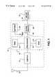
- FIG. 1is a diagrammatic representation of a meter interface unit (“MIU”) constructed in accordance with the present invention
- FIG. 2is a schematic diagram of power management circuitry in accordance with a preferred embodiment of the present invention.
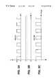
- FIGS. 3A, 3 B and 3 Care respective waveforms showing operation of the step-up and modulated switching circuitry included within the power management circuitry of FIG. 2;
- FIG. 4is a diagrammatic representation of an encoder system having compound registers, with which the MIU of FIG. 1 may be utilized;
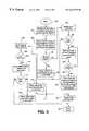
- FIG. 5is a flow chart showing operation of the processor to determine the type of meter encoder and thereafter read usage information therefrom.
- FIG. 1illustrates a meter interface unit (MIU) 10 of the present invention utilized in conjunction with a meter encoder 12 .
- MIUmeter interface unit
- meter encoder 12will function to read usage information from a metering apparatus, such as a mechanical flowmeter.
- a water flowmeterwill generally have mechanical wheels on which water consumption is displayed.
- Meter encoder 12functions to convert the mechanical display into electronic information which is then stored in a local register.
- meter encoder 12may have one register or multiple registers for temporarily storing usage information.
- a water meter having a single flowmeter apparatusmay be equipped with a single register.
- Certain meters, such as those including devices for measuring both high and low levels of flow,may be equipped with multiple storage registers.
- MIU 10is capable of recognizing which type of meter encoder with which it is being used, and to vary its operating characteristics accordingly. As such, MIU 10 overcomes the need frequently seen in the prior art to provide a unique MIU for each meter encoder.
- MIU 10functions to transmit usage information obtained from meter encoder 12 to a remote location for further processing. Because the illustrated embodiment utilizes RF transmission, MIU 10 is equipped with an antenna 14 and a suitable transmitter 16 . Other embodiments, however, may utilize telephone or transmission of another type to send the usage information. Typically, MIU 10 may initiate reading of usage information from meter encoder 12 on a scheduled basis. Preferably, the scheduled time at which reading occurs may be programmable.
- MIU 10includes a microcontroller 18 which is operative to control transmission of usage information obtained from meter encoder 12 .
- Microcontroller 18includes a processor 20 that implements firmware instructions stored in a suitable non-volatile memory, such as read-only memory (ROM) 22 .
- ROMread-only memory
- RAMrandom access memory
- MIU 10further includes power management circuitry 26 functionally interposing microcontroller 18 and meter encoder 12 as shown.
- MIU 10will be located remote from a source of constant electricity.
- MIU 10is equipped with a battery functional to supply a predetermined battery voltage level, V BAT .
- the integrated circuits and other components of MIU 10are fabricated according to newer technology to effectively operate at relatively low voltage levels.
- modern integrated circuitscan often operate effectively at voltage levels of less than 3.6 volts.
- a batterycomprising three cells of 1.2 volts each may thus be used for this purpose.
- power management circuitry 26is configured to step-up the voltage level V BAT to the higher voltage level needed by encoder 12 .
- power management circuitry 26is operative to supply power to meter encoder 12 only at selected times when usage information needs to be obtained. As such, battery life is greatly extended over what would be the case if power were supplied to meter encoder 12 at all times.
- power management circuitry 26functions to provide power to meter encoder 12 at a predetermined frequency which may be varied under the control of microprocessor 20 depending on the type of meter encoder.
- FIG. 2illustrates a schematic of power management circuitry 26 in one preferred implementation.
- circuitry 26is connected to processor 20 through three lines collectively indicated at 30 . The three lines are respectively labeled “ENABLE,” “CLOCK1” and “READ.”
- power management circuitry 26is connected to meter encoder 12 through three lines collectively indicated at 32 . As can be seen, these three lines are respectively labeled “CLOCK2,” “GND” and “DATA.”
- the ENABLE input from processor 20instructs power management circuitry 26 to allow power to be supplied to meter encoder 12 .
- the ENABLE signalis a “low” signal which causes transistor 34 to conduct.
- a voltage V SWITCHwill be produced at the collector of transistor 34 .
- the voltage V SWITCHis the voltage V BAT reduced by the voltage drop across transistor 34 . (The resistance value of resistor 36 will be small in relation to that of resistor 38 .)
- transistor 34When the ENABLE input is high, transistor 34 will be maintained in a non-conducting state by the voltage supplied to its base through resistors 40 and 42 .
- step-up circuitry 44which supplies the higher voltage level necessary to operate meter encoder 12 .
- step-up circuitry 44includes an integrated circuit (IC) 46 which receives the voltage V SWITCH as a power input at its pin 1 .
- IC 46operates to supply a DC output from pin 2 .
- a high frequency output(shown in FIG. 3A) having a peak voltage level V SWITCH is supplied from pin 5 .
- the frequency of the pin 5 outputwill be many times the clock frequency used to read usage information from the meter encoder.
- the output of pin 5may have a frequency of approximately 300 kilohertz or greater.
- a suitable integrated circuit for use as IC 46is available under Part No. ISC8321 from Vishay.
- the DC output from pin 2 of IC 46is applied to one terminal of a capacitor 48 .
- capacitor 48will be charged up to at least this voltage level.
- the output of pin 5is applied to a terminal interconnecting a diode 50 and an inductor 52 .
- Inductor 52is, in turn, connected to voltage V BAT .
- a pulse width modulated (PWM) signalis supplied as an output from pin 5 of IC 46 . It should be appreciated, however, that other suitable output signals, such as frequency modulated or pulse frequency modulated signals, may also be supplied.
- Meter encodersare typically configured to receive operational power as a pulse width input having a predetermined frequency and duty cycle. For example, many meter encoders are configured to operate at a frequency of 1200 hertz and 50% duty cycle. Other meter encoders, such as those having multiple registers, are often designed to operate at higher frequencies. For example, some encoders having compound registers are designed to operate from a 19.2 kilohertz input signal of 50% duty cycle. In addition to supplying power to the meter encoder, the square wave input provides a clock signal against which output of the encoder's register is synchronized.
- processor 20is operative to identify meter encoder 12 from among several known types. Depending on the type of meter encoder that is identified, the clock frequency that is output by microprocessor 20 may be varied accordingly. This clock signal is received by power management circuitry 26 along the CLOCK 1 input. The clock signal is then applied to switching circuitry 54 which modulates the voltage across capacitor 48 .
- FIG. 3Cillustrates the modulated output of switching circuitry 54 .
- switching circuitry 54is “chopping” the DC voltage on capacitor 48 at a frequency of 19.2 kHz. Because 19.2 kHz is about 15.63 times lower in frequency than the 300 kHz output from pin 5 of IC 46 , the time scale in FIG. 3C has been compressed by a like amount. Otherwise, each pulse in FIG. 3C would extend beyond the period shown in FIGS. 3A and 3B.
- Switching circuitry 54includes a pair of field effect transistors (FETs) 56 and 58 arranged in series as shown.
- a biasing resistor 60is connected across FETs 56 and 58 to limit current flowing through FET 58 .
- FETsfield effect transistors
- a resistor 62is provided to limit current flowing into meter encoder 12 .
- a resistor 64is provided to “pull down” the CLOCK 2 input of meter encoder 12 when power is not being applied.
- Usage informationis read from meter encoder 12 at its DATA output.
- the informationis detected by processor 20 along the READ line of power management circuitry 26 .
- a pair of grounded capacitors 68 and 70are connected on respective sides of diode 66 to filter noise that may be present in the data signal. This is particularly advantageous in view of the relatively long distance that may separate MIU 10 and meter encoder 12 . Often, even if a higher frequency signal (e.g., 19.2 kHz) is used to power the meter encoder, the data will still be read out at a lower frequency (e.g., 1200 Hz).
- a higher frequency signale.g., 19.2 kHz
- Voltage level V SWITCHis applied to the READ line through a resistor 72 for reducing the voltage of the data fed from meter encoder 12 to the lower voltage level at which components of MIU 10 operate.
- a common groundas indicated by the GND line extending between power management circuitry 26 and meter encoder 12 , provides a common ground level for reference purposes.
- meter encoder 12includes a pair of reader circuits 74 and 76 associated with a respective mechanical consumption meter.
- the meter associated with circuit 74may indicate consumption of water at low levels of flow.
- the meter associated with circuit 76may be configured to indicate consumption of water at higher flow levels.
- Each of the meterswill typically include mechanical wheels which are read, and converted to electronic data. The electronic data, in turn, is stored in respective registers 78 and 80 .
- the CLOCK 2 , GND and DATA linesextend to register 78 , which has three like lines extending to register 80 .
- Poweris fed to meter encoder 12 by the CLOCK 2 output of power management circuitry 26 .
- the frequency of the clock signalis utilized as a basis for synchronizing the output of electronic information along the DATA line.
- the power signal passesis also used to charge a capacitor inside of register 78 .
- the frequency and duty cycle of the clock signalis chosen so that the capacitor will stay charged sufficiently to allow data to be read from the encoder.
- MIU 10includes appropriate firmware permitting it to recognize meter encoder 12 from several possible alternatives.
- FIG. 5illustrates exemplary method steps that may be implemented by processor 20 to perform this function.
- block 82represents the start of the program. Once processor 20 is powered up, the program starts executing from the beginning. The program then moves to the next function, indicated by block 84 . At this point, initialization and power up configuration tasks are performed. The program initializes the I/O ports, timers and registers of processor 20 to the correct stage. At the end of the initialization, the program starts the main loop to read, verify and transmit the usage information via RF protocol.
- an ENABLE signalis sent to power management circuitry 26 .
- Processor 20configures itself to accept data from the encoder register.
- a predetermined clock of a first frequencysuch as 1200 hertz, is begun to cause reading a first type of encoder.
- a 1200 hertz clockcan be initiated to read data from a “ProRead” encoder marketed by Schlumberger RMS.
- the programmoves to decision block 88 , where it verifies that the data being received from the meter encoder is of the ProRead type. If the data is of the ProRead type, the program moves to block 90 .
- the datais verified for undesirable opens (“-”) or shorts (“H”).
- the term “open”means that there is no electrical contact with one or more of the mechanical wheels in the consumption meter.
- shortmeans that two digits are being shorted together to give an invalid reading.
- processor 20causes the transmit function to transmit the data with the correct ID and account number. After the data has been transmitted, the microprocessor is again powered down, as indicated at 94 .
- the programmoves to block 90 if the data does not identify the first expected type of meter encoder.
- Processor 20may then send power of a second predetermined frequency to meter encoder 12 .
- a 19.2 kilohertz signalmay be sent.
- the programdetermines whether any data is being received from meter encoder 12 . For example, the program may wait at least 300 milliseconds for ProRead network data. If the data starts coming within 300 milliseconds, then the program may move to block 100 .
- the programlooks for the network number. Usage information from each available register will be pulled and saved until all of the registers are read, as indicated at decision block 102 .
- the programmoves to block 104 .
- This functionverifies the data for opens and shorts, and adjusts the transmit interval time in ROM 22 to transmit the network data one register data at a time at a shorter interval time with proper ID and account numbers.
- This functionconverts the data to a BCD format. A number is loaded in the flag byte which indicates the number of registers' data that needs to be transmitted from the last read.
- the main moduleis forced to retrieve the data from ROM 22 for transmission with a shorter interval, which will preferably be the same for each register.
- the programproceeds to block 92 for transmission and block 94 for power down as described above.
- the programmoves to block 106 .
- the programwill now check to determine whether meter encoder 12 is of another known type. For example, a 1200 hertz clock signal may be sent to meter encoder 12 to determine whether a Sensus meter encoder is present.
- the programverifies whether the data received from meter encoder 12 appears to be of the Sensus type. If so, the program moves to block 110 .
- the datais converted to a BCD format and placed in the transmit buffer for transmission at block 92 .
- the programmoves to block 112 where it begins checking for another known type of meter encoder. For example, the program may send a 1200 hertz clock to meter encoder 12 to determine whether a ARB V encoder is present. The data is read twice from the ARB V encoder so that the two readings can be compared (since there is no checksum in this case).
- the programdetermines whether valid data is being received. If data is present in the “DATA” line, then the program moves to block 116 . At this point, the program checks for opens and shorts, and converts the data to a BCD format. The converted data is then placed in the transmit buffer for transmission, as indicated at block 92 .
Landscapes
- Engineering & Computer Science (AREA)
- Computer Networks & Wireless Communication (AREA)
- Arrangements For Transmission Of Measured Signals (AREA)
Abstract
Description
Claims (34)
Priority Applications (2)
| Application Number | Priority Date | Filing Date | Title |
|---|---|---|---|
| US09/183,645US6424270B1 (en) | 1998-10-30 | 1998-10-30 | Utility meter interface unit |
| CA002271409ACA2271409A1 (en) | 1998-10-30 | 1999-05-10 | Utility meter interface unit |
Applications Claiming Priority (1)
| Application Number | Priority Date | Filing Date | Title |
|---|---|---|---|
| US09/183,645US6424270B1 (en) | 1998-10-30 | 1998-10-30 | Utility meter interface unit |
Publications (1)
| Publication Number | Publication Date |
|---|---|
| US6424270B1true US6424270B1 (en) | 2002-07-23 |
Family
ID=22673712
Family Applications (1)
| Application Number | Title | Priority Date | Filing Date |
|---|---|---|---|
| US09/183,645Expired - LifetimeUS6424270B1 (en) | 1998-10-30 | 1998-10-30 | Utility meter interface unit |
Country Status (2)
| Country | Link |
|---|---|
| US (1) | US6424270B1 (en) |
| CA (1) | CA2271409A1 (en) |
Cited By (79)
| Publication number | Priority date | Publication date | Assignee | Title |
|---|---|---|---|---|
| US20020163442A1 (en)* | 2001-05-02 | 2002-11-07 | Invensys Metering Systems/North America Inc. | Automatic meter reading module |
| US6756914B1 (en)* | 1999-11-12 | 2004-06-29 | Itron, Inc. | Low impedance encoder for a utility meter |
| US20050060105A1 (en)* | 2002-11-12 | 2005-03-17 | Paul Lander | Tracking vibrations in a pipeline network |
| WO2005047828A1 (en)* | 2003-11-04 | 2005-05-26 | Neptune Technology Group, Inc. | Communications and features protocol for a measuring water meter |
| US20050279169A1 (en)* | 2002-11-12 | 2005-12-22 | Paul Lander | Tracking vibrations in a pipeline network |
| US7053767B2 (en) | 1998-06-22 | 2006-05-30 | Statsignal Systems, Inc. | System and method for monitoring and controlling remote devices |
| US7079810B2 (en) | 1997-02-14 | 2006-07-18 | Statsignal Ipc, Llc | System and method for communicating with a remote communication unit via the public switched telephone network (PSTN) |
| US7103511B2 (en) | 1998-10-14 | 2006-09-05 | Statsignal Ipc, Llc | Wireless communication networks for providing remote monitoring of devices |
| US7137550B1 (en) | 1997-02-14 | 2006-11-21 | Statsignal Ipc, Llc | Transmitter for accessing automated financial transaction machines |
| US20070038394A1 (en)* | 2004-04-01 | 2007-02-15 | Stephan Gagnon | System and method for reading power meters |
| US7209840B2 (en) | 2000-08-09 | 2007-04-24 | Hunt Technologies, Llc | Systems and methods for providing remote monitoring of electricity consumption for an electric meter |
| US7263073B2 (en) | 1999-03-18 | 2007-08-28 | Statsignal Ipc, Llc | Systems and methods for enabling a mobile user to notify an automated monitoring system of an emergency situation |
| US7295128B2 (en) | 1998-06-22 | 2007-11-13 | Sipco, Llc | Smoke detection methods, devices, and systems |
| US20080024320A1 (en)* | 1999-02-23 | 2008-01-31 | Ehrke Lance A | Electronic electric meter for networked meter reading |
| US7333903B2 (en) | 2005-09-12 | 2008-02-19 | Acuity Brands, Inc. | Light management system having networked intelligent luminaire managers with enhanced diagnostics capabilities |
| US7346463B2 (en) | 2001-08-09 | 2008-03-18 | Hunt Technologies, Llc | System for controlling electrically-powered devices in an electrical network |
| US20080068989A1 (en)* | 2006-09-15 | 2008-03-20 | Wyk Hartman V | Cell size management |
| US20080068215A1 (en)* | 2006-09-15 | 2008-03-20 | Stuber Michael T G | Home area networking (HAN) with low power considerations for battery devices |
| US20080086394A1 (en)* | 2006-06-29 | 2008-04-10 | Carina Technology, Inc. | System and method for controlling a utility meter |
| US20080094248A1 (en)* | 2006-10-19 | 2008-04-24 | Lakich Daniel M | Extending contact life in remote disconnect applications |
| US20080129538A1 (en)* | 1999-02-23 | 2008-06-05 | Raj Vaswani | Electronic electric meter for networked meter reading |
| US20080154624A1 (en)* | 2006-06-29 | 2008-06-26 | Carina Technology, Inc. | System and method for monitoring, controlling, and displaying utility information |
| US7397907B2 (en) | 1997-02-14 | 2008-07-08 | Sipco, Llc | Multi-function general purpose transceiver |
| US7424527B2 (en) | 2001-10-30 | 2008-09-09 | Sipco, Llc | System and method for transmitting pollution information over an integrated wireless network |
| US7480501B2 (en) | 2001-10-24 | 2009-01-20 | Statsignal Ipc, Llc | System and method for transmitting an emergency message over an integrated wireless network |
| GB2453325A (en)* | 2007-10-01 | 2009-04-08 | Npower | Monitoring utility consumption |
| US20090188315A1 (en)* | 2007-02-06 | 2009-07-30 | Dresser, Inc. | Instruments for flow meters |
| US20090287838A1 (en)* | 2002-11-18 | 2009-11-19 | Seyamak Keyghobad | Method and apparatus for inexpensively monitoring and controlling remotely distributed appliances |
| US20090309755A1 (en)* | 2006-05-04 | 2009-12-17 | Capstone Mobile Techologies Llc | System and method for remotely monitoring and controlling a water meter |
| US7650425B2 (en) | 1999-03-18 | 2010-01-19 | Sipco, Llc | System and method for controlling communication between a host computer and communication devices associated with remote devices in an automated monitoring system |
| US20100045479A1 (en)* | 2008-08-20 | 2010-02-25 | Landis+Gyr, Inc. | Remote communications feedback for utility meter |
| US7688220B2 (en) | 2005-12-16 | 2010-03-30 | Hunt Power, L.P. | Device and method for processing meter data from multiple meters |
| US7697492B2 (en) | 1998-06-22 | 2010-04-13 | Sipco, Llc | Systems and methods for monitoring and controlling remote devices |
| US7741976B2 (en) | 2005-12-16 | 2010-06-22 | Hunt Power, L.P. | Server and method for processing meter data into a common format |
| US7756086B2 (en) | 2004-03-03 | 2010-07-13 | Sipco, Llc | Method for communicating in dual-modes |
| US7817063B2 (en) | 2005-10-05 | 2010-10-19 | Abl Ip Holding Llc | Method and system for remotely monitoring and controlling field devices with a street lamp elevated mesh network |
| US20100295672A1 (en)* | 2009-05-22 | 2010-11-25 | Mueller International, Inc. | Infrastructure monitoring devices, systems, and methods |
| US7843391B2 (en) | 2006-09-15 | 2010-11-30 | Itron, Inc. | RF local area network antenna design |
| US7847536B2 (en) | 2006-08-31 | 2010-12-07 | Itron, Inc. | Hall sensor with temperature drift control |
| US20100321205A1 (en)* | 2009-06-23 | 2010-12-23 | Olson John A | AMR Transmitter And Method Using Multiple Radio Messages |
| US20110062298A1 (en)* | 2009-09-11 | 2011-03-17 | Elster Amco Water, Inc. | Horizontal pit mount interface device |
| US20110063124A1 (en)* | 2009-09-11 | 2011-03-17 | Elster Amco Water, Inc. | Pit mount interface device |
| US8000314B2 (en) | 1996-12-06 | 2011-08-16 | Ipco, Llc | Wireless network system and method for providing same |
| US8024724B2 (en) | 2006-08-31 | 2011-09-20 | Itron, Inc. | Firmware download |
| US8031650B2 (en) | 2004-03-03 | 2011-10-04 | Sipco, Llc | System and method for monitoring remote devices with a dual-mode wireless communication protocol |
| US8049642B2 (en) | 2006-09-05 | 2011-11-01 | Itron, Inc. | Load side voltage sensing for AMI metrology |
| US8055461B2 (en) | 2006-09-15 | 2011-11-08 | Itron, Inc. | Distributing metering responses for load balancing an AMR network |
| US8064412B2 (en) | 1998-06-22 | 2011-11-22 | Sipco, Llc | Systems and methods for monitoring conditions |
| US20120026006A1 (en)* | 2004-10-05 | 2012-02-02 | Electro Industries/Gauge Tech | Meter having a communication interface for receiving and interfacing with a communication device |
| US20120026007A1 (en)* | 2009-03-06 | 2012-02-02 | Utility Metering Services Limited | Utility Meter and Method of Operation |
| US8138944B2 (en) | 2006-09-15 | 2012-03-20 | Itron, Inc. | Home area networking (HAN) with handheld for diagnostics |
| US8140276B2 (en) | 2008-02-27 | 2012-03-20 | Abl Ip Holding Llc | System and method for streetlight monitoring diagnostics |
| US8212687B2 (en) | 2006-09-15 | 2012-07-03 | Itron, Inc. | Load side voltage sensing for AMI metrology |
| US8312103B2 (en) | 2006-08-31 | 2012-11-13 | Itron, Inc. | Periodic balanced communication node and server assignment |
| US20130013261A1 (en)* | 2011-07-06 | 2013-01-10 | Nxp B.V. | Metering system having improved security |
| US8410931B2 (en) | 1998-06-22 | 2013-04-02 | Sipco, Llc | Mobile inventory unit monitoring systems and methods |
| US8489063B2 (en) | 2001-10-24 | 2013-07-16 | Sipco, Llc | Systems and methods for providing emergency messages to a mobile device |
| US8660134B2 (en) | 2011-10-27 | 2014-02-25 | Mueller International, Llc | Systems and methods for time-based hailing of radio frequency devices |
| US8690117B2 (en) | 2006-05-04 | 2014-04-08 | Capstone Metering Llc | Water meter |
| US8787210B2 (en) | 2006-09-15 | 2014-07-22 | Itron, Inc. | Firmware download with adaptive lost packet recovery |
| US8787246B2 (en) | 2009-02-03 | 2014-07-22 | Ipco, Llc | Systems and methods for facilitating wireless network communication, satellite-based wireless network systems, and aircraft-based wireless network systems, and related methods |
| US8833390B2 (en) | 2011-05-31 | 2014-09-16 | Mueller International, Llc | Valve meter assembly and method |
| US8855569B2 (en) | 2011-10-27 | 2014-10-07 | Mueller International, Llc | Systems and methods for dynamic squelching in radio frequency devices |
| US8931505B2 (en) | 2010-06-16 | 2015-01-13 | Gregory E. HYLAND | Infrastructure monitoring devices, systems, and methods |
| US9202362B2 (en) | 2008-10-27 | 2015-12-01 | Mueller International, Llc | Infrastructure monitoring system and method |
| US9419888B2 (en) | 2011-12-22 | 2016-08-16 | Itron, Inc. | Cell router failure detection in a mesh network |
| US9439126B2 (en) | 2005-01-25 | 2016-09-06 | Sipco, Llc | Wireless network protocol system and methods |
| US9494249B2 (en) | 2014-05-09 | 2016-11-15 | Mueller International, Llc | Mechanical stop for actuator and orifice |
| US9565620B2 (en) | 2014-09-02 | 2017-02-07 | Mueller International, Llc | Dynamic routing in a mesh network |
| US10180414B2 (en) | 2013-03-15 | 2019-01-15 | Mueller International, Llc | Systems for measuring properties of water in a water distribution system |
| US10200476B2 (en) | 2011-10-18 | 2019-02-05 | Itron, Inc. | Traffic management and remote configuration in a gateway-based network |
| US10587278B2 (en) | 2018-02-20 | 2020-03-10 | F.S. Brainard & Company | Sensor to encoder signal converter |
| US10627254B2 (en) | 2018-04-04 | 2020-04-21 | F.S. Brainard & Co. | Low interference sub-meter and monitoring system |
| US20200128308A1 (en)* | 2017-06-29 | 2020-04-23 | Diehl Metering Systems Gmbh | Communication module for capturing consumption data from a meter |
| US10833799B2 (en) | 2018-05-31 | 2020-11-10 | Itron Global Sarl | Message correction and dynamic correction adjustment for communication systems |
| US10948132B2 (en) | 2017-05-08 | 2021-03-16 | 64Seconds, Inc. | Integrity assessment of a pipeline network |
| US11041839B2 (en) | 2015-06-05 | 2021-06-22 | Mueller International, Llc | Distribution system monitoring |
| US11516899B2 (en) | 2015-05-27 | 2022-11-29 | Electro Industries/Gauge Tech | Devices, systems and methods for electrical utility submetering |
| US11725366B2 (en) | 2020-07-16 | 2023-08-15 | Mueller International, Llc | Remote-operated flushing system |
Citations (25)
| Publication number | Priority date | Publication date | Assignee | Title |
|---|---|---|---|---|
| US3676875A (en)* | 1970-03-10 | 1972-07-11 | Westinghouse Electric Corp | Method and apparatus for transmitting information in meter reading |
| US3697970A (en)* | 1970-06-17 | 1972-10-10 | William W Jaxheimer | Electrical meter reading system |
| US4439764A (en)* | 1981-04-09 | 1984-03-27 | Westinghouse Electric Corp. | Dual mode meter reading apparatus |
| US4642634A (en)* | 1984-09-18 | 1987-02-10 | Ncr Corporation | Optical encoder |
| US4642635A (en)* | 1981-11-30 | 1987-02-10 | Snaper Alvin A | Remote meter reading system |
| US4804957A (en)* | 1985-11-27 | 1989-02-14 | Triad Communications, Inc. | Utility meter and submetering system |
| US4839642A (en) | 1985-01-22 | 1989-06-13 | Northern Illinois Gas Company | Data transmission system with data verification |
| US5252967A (en)* | 1990-05-25 | 1993-10-12 | Schlumberger Industries, Inc. | Reader/programmer for two and three wire utility data communications system |
| US5448230A (en)* | 1993-06-25 | 1995-09-05 | Metscan, Incorporated | Remote data acquisition and communication system |
| US5451938A (en)* | 1993-10-22 | 1995-09-19 | Schlumberger Industries, Inc. | RF meter reading system |
| US5544089A (en) | 1992-02-21 | 1996-08-06 | Abb Power T&D Company Inc. | Programmable electrical energy meter using multiplexed analog-to-digital converters |
| US5553094A (en) | 1990-02-15 | 1996-09-03 | Iris Systems, Inc. | Radio communication network for remote data generating stations |
| US5594431A (en)* | 1992-03-19 | 1997-01-14 | Abb Kent Plc | Remote meter reading |
| US5602744A (en)* | 1994-09-29 | 1997-02-11 | Meek; Jean L. | Universal send/receive utility usage data gathering system |
| US5625353A (en)* | 1992-12-29 | 1997-04-29 | Kabushiki Kaisha Sankyo Seiki Seisakusho | Device for transmitting signals from position detector and method of such signal transmission |
| US5682422A (en)* | 1995-08-25 | 1997-10-28 | International Teldata Corporation | Apparatus and method for on-demand activation of telephone line telemetry devices |
| US5726646A (en)* | 1994-04-04 | 1998-03-10 | Motorola, Inc. | Method and apparatus for activating and accessing remote meter interface devices |
| US5796250A (en)* | 1993-05-01 | 1998-08-18 | Scientific Generics Limited | Plural rotary member position encoder having electromagnetically coupled resonant frequency multiplexed outputs for respectively associated rotatable members |
| US5835025A (en)* | 1997-05-14 | 1998-11-10 | U.S. Army Corps Of Engineers As Represented By The Secretary Of The Army | Portable battery operated power managed event recorder and interrogator system |
| US6006212A (en)* | 1997-09-17 | 1999-12-21 | Itron, Inc. | Time-of-use and demand metering in conditions of power outage with a mobile node |
| US6088659A (en) | 1997-09-11 | 2000-07-11 | Abb Power T&D Company Inc. | Automated meter reading system |
| US6094622A (en) | 1996-10-22 | 2000-07-25 | Abb Power T&D Company Inc. | System and method for automatically determining the electrical energy service type to which an energy meter is connected |
| US6177883B1 (en) | 1998-09-02 | 2001-01-23 | Schlumberger Resource Management Services, Inc. | Utility meter transponder exposed ground level antenna assembly |
| US6232886B1 (en) | 1998-12-23 | 2001-05-15 | Schlumberger Resource Management Services, Inc. | Method and apparatus for indicating meter tampering |
| US6232885B1 (en) | 1998-10-15 | 2001-05-15 | Schlumberger Resource Management Services, Inc. | Electricity meter |
- 1998
- 1998-10-30USUS09/183,645patent/US6424270B1/ennot_activeExpired - Lifetime
- 1999
- 1999-05-10CACA002271409Apatent/CA2271409A1/ennot_activeAbandoned
Patent Citations (29)
| Publication number | Priority date | Publication date | Assignee | Title |
|---|---|---|---|---|
| US3676875A (en)* | 1970-03-10 | 1972-07-11 | Westinghouse Electric Corp | Method and apparatus for transmitting information in meter reading |
| US3697970A (en)* | 1970-06-17 | 1972-10-10 | William W Jaxheimer | Electrical meter reading system |
| US4439764A (en)* | 1981-04-09 | 1984-03-27 | Westinghouse Electric Corp. | Dual mode meter reading apparatus |
| US4642635A (en)* | 1981-11-30 | 1987-02-10 | Snaper Alvin A | Remote meter reading system |
| US4642634A (en)* | 1984-09-18 | 1987-02-10 | Ncr Corporation | Optical encoder |
| US4839642A (en) | 1985-01-22 | 1989-06-13 | Northern Illinois Gas Company | Data transmission system with data verification |
| US4804957A (en)* | 1985-11-27 | 1989-02-14 | Triad Communications, Inc. | Utility meter and submetering system |
| US5553094A (en) | 1990-02-15 | 1996-09-03 | Iris Systems, Inc. | Radio communication network for remote data generating stations |
| US5252967A (en)* | 1990-05-25 | 1993-10-12 | Schlumberger Industries, Inc. | Reader/programmer for two and three wire utility data communications system |
| US5631843A (en) | 1992-02-21 | 1997-05-20 | Abb Power T&D Company Inc. | Programmable electrical energy meter and methods therefor |
| US5555508A (en) | 1992-02-21 | 1996-09-10 | Abb Power T&D Company Inc. | Programmable electrical energy meter and methods therefor |
| US5544089A (en) | 1992-02-21 | 1996-08-06 | Abb Power T&D Company Inc. | Programmable electrical energy meter using multiplexed analog-to-digital converters |
| US5548527A (en) | 1992-02-21 | 1996-08-20 | Abb Power T&D Company Inc. | Programmable electrical energy meter utilizing a non-volatile memory |
| US5594431A (en)* | 1992-03-19 | 1997-01-14 | Abb Kent Plc | Remote meter reading |
| US5815089A (en)* | 1992-12-29 | 1998-09-29 | Kabushiki Kaisha Sankyo Seiki Seisakusho | Device for transmitting signals from position detector and method of such signal transmission |
| US5625353A (en)* | 1992-12-29 | 1997-04-29 | Kabushiki Kaisha Sankyo Seiki Seisakusho | Device for transmitting signals from position detector and method of such signal transmission |
| US5796250A (en)* | 1993-05-01 | 1998-08-18 | Scientific Generics Limited | Plural rotary member position encoder having electromagnetically coupled resonant frequency multiplexed outputs for respectively associated rotatable members |
| US5448230A (en)* | 1993-06-25 | 1995-09-05 | Metscan, Incorporated | Remote data acquisition and communication system |
| US5451938A (en)* | 1993-10-22 | 1995-09-19 | Schlumberger Industries, Inc. | RF meter reading system |
| US5726646A (en)* | 1994-04-04 | 1998-03-10 | Motorola, Inc. | Method and apparatus for activating and accessing remote meter interface devices |
| US5602744A (en)* | 1994-09-29 | 1997-02-11 | Meek; Jean L. | Universal send/receive utility usage data gathering system |
| US5682422A (en)* | 1995-08-25 | 1997-10-28 | International Teldata Corporation | Apparatus and method for on-demand activation of telephone line telemetry devices |
| US6094622A (en) | 1996-10-22 | 2000-07-25 | Abb Power T&D Company Inc. | System and method for automatically determining the electrical energy service type to which an energy meter is connected |
| US5835025A (en)* | 1997-05-14 | 1998-11-10 | U.S. Army Corps Of Engineers As Represented By The Secretary Of The Army | Portable battery operated power managed event recorder and interrogator system |
| US6088659A (en) | 1997-09-11 | 2000-07-11 | Abb Power T&D Company Inc. | Automated meter reading system |
| US6006212A (en)* | 1997-09-17 | 1999-12-21 | Itron, Inc. | Time-of-use and demand metering in conditions of power outage with a mobile node |
| US6177883B1 (en) | 1998-09-02 | 2001-01-23 | Schlumberger Resource Management Services, Inc. | Utility meter transponder exposed ground level antenna assembly |
| US6232885B1 (en) | 1998-10-15 | 2001-05-15 | Schlumberger Resource Management Services, Inc. | Electricity meter |
| US6232886B1 (en) | 1998-12-23 | 2001-05-15 | Schlumberger Resource Management Services, Inc. | Method and apparatus for indicating meter tampering |
Non-Patent Citations (2)
| Title |
|---|
| Hamilton, David, "Self-Powered Fluid Meter," U.S. Patent application Ser. No. 09/754/025, filed Jan. 3, 2001. |
| Makison, David, Philpot, Ludlow, "Modular Meter Configuration and Methodology," U.S. Patent application Ser. No. 09/450,890 filed Nov. 29, 1999. |
Cited By (194)
| Publication number | Priority date | Publication date | Assignee | Title |
|---|---|---|---|---|
| US8625496B2 (en) | 1996-12-06 | 2014-01-07 | Ipco, Llc | Wireless network system and method for providing same |
| US8233471B2 (en) | 1996-12-06 | 2012-07-31 | Ipco, Llc | Wireless network system and method for providing same |
| US8000314B2 (en) | 1996-12-06 | 2011-08-16 | Ipco, Llc | Wireless network system and method for providing same |
| US8982856B2 (en) | 1996-12-06 | 2015-03-17 | Ipco, Llc | Systems and methods for facilitating wireless network communication, satellite-based wireless network systems, and aircraft-based wireless network systems, and related methods |
| US7137550B1 (en) | 1997-02-14 | 2006-11-21 | Statsignal Ipc, Llc | Transmitter for accessing automated financial transaction machines |
| US7397907B2 (en) | 1997-02-14 | 2008-07-08 | Sipco, Llc | Multi-function general purpose transceiver |
| US7079810B2 (en) | 1997-02-14 | 2006-07-18 | Statsignal Ipc, Llc | System and method for communicating with a remote communication unit via the public switched telephone network (PSTN) |
| US20100141474A1 (en)* | 1997-09-05 | 2010-06-10 | Ehrke Lance A | Electronic electric meter for networked meter reading |
| US7295128B2 (en) | 1998-06-22 | 2007-11-13 | Sipco, Llc | Smoke detection methods, devices, and systems |
| US8212667B2 (en) | 1998-06-22 | 2012-07-03 | Sipco, Llc | Automotive diagnostic data monitoring systems and methods |
| US8013732B2 (en) | 1998-06-22 | 2011-09-06 | Sipco, Llc | Systems and methods for monitoring and controlling remote devices |
| US9571582B2 (en) | 1998-06-22 | 2017-02-14 | Sipco, Llc | Systems and methods for monitoring and controlling remote devices |
| US7053767B2 (en) | 1998-06-22 | 2006-05-30 | Statsignal Systems, Inc. | System and method for monitoring and controlling remote devices |
| US8410931B2 (en) | 1998-06-22 | 2013-04-02 | Sipco, Llc | Mobile inventory unit monitoring systems and methods |
| US9129497B2 (en) | 1998-06-22 | 2015-09-08 | Statsignal Systems, Inc. | Systems and methods for monitoring conditions |
| US9691263B2 (en) | 1998-06-22 | 2017-06-27 | Sipco, Llc | Systems and methods for monitoring conditions |
| US7697492B2 (en) | 1998-06-22 | 2010-04-13 | Sipco, Llc | Systems and methods for monitoring and controlling remote devices |
| US8964708B2 (en) | 1998-06-22 | 2015-02-24 | Sipco Llc | Systems and methods for monitoring and controlling remote devices |
| US8064412B2 (en) | 1998-06-22 | 2011-11-22 | Sipco, Llc | Systems and methods for monitoring conditions |
| US8223010B2 (en) | 1998-06-22 | 2012-07-17 | Sipco Llc | Systems and methods for monitoring vehicle parking |
| US9430936B2 (en) | 1998-06-22 | 2016-08-30 | Sipco Llc | Systems and methods for monitoring and controlling remote devices |
| US7103511B2 (en) | 1998-10-14 | 2006-09-05 | Statsignal Ipc, Llc | Wireless communication networks for providing remote monitoring of devices |
| US20080024320A1 (en)* | 1999-02-23 | 2008-01-31 | Ehrke Lance A | Electronic electric meter for networked meter reading |
| US20080129538A1 (en)* | 1999-02-23 | 2008-06-05 | Raj Vaswani | Electronic electric meter for networked meter reading |
| US8930571B2 (en) | 1999-03-18 | 2015-01-06 | Sipco, LLP | Systems and methods for controlling communication between a host computer and communication devices |
| US8924587B2 (en) | 1999-03-18 | 2014-12-30 | Sipco, Llc | Systems and methods for controlling communication between a host computer and communication devices |
| US8924588B2 (en) | 1999-03-18 | 2014-12-30 | Sipco, Llc | Systems and methods for controlling communication between a host computer and communication devices |
| US7263073B2 (en) | 1999-03-18 | 2007-08-28 | Statsignal Ipc, Llc | Systems and methods for enabling a mobile user to notify an automated monitoring system of an emergency situation |
| US7650425B2 (en) | 1999-03-18 | 2010-01-19 | Sipco, Llc | System and method for controlling communication between a host computer and communication devices associated with remote devices in an automated monitoring system |
| US6756914B1 (en)* | 1999-11-12 | 2004-06-29 | Itron, Inc. | Low impedance encoder for a utility meter |
| US7209840B2 (en) | 2000-08-09 | 2007-04-24 | Hunt Technologies, Llc | Systems and methods for providing remote monitoring of electricity consumption for an electric meter |
| US20020163442A1 (en)* | 2001-05-02 | 2002-11-07 | Invensys Metering Systems/North America Inc. | Automatic meter reading module |
| US6982651B2 (en)* | 2001-05-02 | 2006-01-03 | M & Fc Holding, Llc | Automatic meter reading module |
| US7346463B2 (en) | 2001-08-09 | 2008-03-18 | Hunt Technologies, Llc | System for controlling electrically-powered devices in an electrical network |
| US8489063B2 (en) | 2001-10-24 | 2013-07-16 | Sipco, Llc | Systems and methods for providing emergency messages to a mobile device |
| US7480501B2 (en) | 2001-10-24 | 2009-01-20 | Statsignal Ipc, Llc | System and method for transmitting an emergency message over an integrated wireless network |
| US9615226B2 (en) | 2001-10-24 | 2017-04-04 | Sipco, Llc | System and method for transmitting an emergency message over an integrated wireless network |
| US8666357B2 (en) | 2001-10-24 | 2014-03-04 | Sipco, Llc | System and method for transmitting an emergency message over an integrated wireless network |
| US10149129B2 (en) | 2001-10-24 | 2018-12-04 | Sipco, Llc | Systems and methods for providing emergency messages to a mobile device |
| US10687194B2 (en) | 2001-10-24 | 2020-06-16 | Sipco, Llc | Systems and methods for providing emergency messages to a mobile device |
| US9282029B2 (en) | 2001-10-24 | 2016-03-08 | Sipco, Llc. | System and method for transmitting an emergency message over an integrated wireless network |
| US8171136B2 (en) | 2001-10-30 | 2012-05-01 | Sipco, Llc | System and method for transmitting pollution information over an integrated wireless network |
| US7424527B2 (en) | 2001-10-30 | 2008-09-09 | Sipco, Llc | System and method for transmitting pollution information over an integrated wireless network |
| US9111240B2 (en) | 2001-10-30 | 2015-08-18 | Sipco, Llc. | System and method for transmitting pollution information over an integrated wireless network |
| US9515691B2 (en) | 2001-10-30 | 2016-12-06 | Sipco, Llc. | System and method for transmitting pollution information over an integrated wireless network |
| US7596458B2 (en) | 2002-11-12 | 2009-09-29 | Flow Metrix, Inc. | Tracking vibrations in a pipeline network |
| US20070130317A1 (en)* | 2002-11-12 | 2007-06-07 | Flow Metrix, Inc. | Tracking vibrations in a pipeline network |
| US7668670B2 (en) | 2002-11-12 | 2010-02-23 | Itron, Inc. | Tracking vibrations in a pipeline network |
| US7891246B2 (en)* | 2002-11-12 | 2011-02-22 | Itron, Inc. | Tracking vibrations in a pipeline network |
| US20050279169A1 (en)* | 2002-11-12 | 2005-12-22 | Paul Lander | Tracking vibrations in a pipeline network |
| US20050060105A1 (en)* | 2002-11-12 | 2005-03-17 | Paul Lander | Tracking vibrations in a pipeline network |
| US20090287838A1 (en)* | 2002-11-18 | 2009-11-19 | Seyamak Keyghobad | Method and apparatus for inexpensively monitoring and controlling remotely distributed appliances |
| US8549131B2 (en) | 2002-11-18 | 2013-10-01 | Mueller International, Llc | Method and apparatus for inexpensively monitoring and controlling remotely distributed appliances |
| US20090319853A1 (en)* | 2002-11-18 | 2009-12-24 | Seyamak Keyghobad | Method and apparatus for inexpensively monitoring and controlling remotely distributed appliances |
| US7783738B2 (en) | 2002-11-18 | 2010-08-24 | Mueller International, Inc. | Method and apparatus for inexpensively monitoring and controlling remotely distributed appliances |
| US7792946B2 (en) | 2002-11-18 | 2010-09-07 | Mueller International, Inc. | Method and apparatus for inexpensively monitoring and controlling remotely distributed appliances |
| US8407333B2 (en) | 2002-11-18 | 2013-03-26 | Mueller International, Llc | Method and apparatus for inexpensively monitoring and controlling remotely distributed appliances |
| US8140667B2 (en) | 2002-11-18 | 2012-03-20 | Mueller International, Llc | Method and apparatus for inexpensively monitoring and controlling remotely distributed appliances |
| US7752309B2 (en) | 2002-11-18 | 2010-07-06 | Mueller International, Inc. | Method and apparatus for inexpensively monitoring and controlling remotely distributed appliances |
| WO2005047828A1 (en)* | 2003-11-04 | 2005-05-26 | Neptune Technology Group, Inc. | Communications and features protocol for a measuring water meter |
| US8031650B2 (en) | 2004-03-03 | 2011-10-04 | Sipco, Llc | System and method for monitoring remote devices with a dual-mode wireless communication protocol |
| US7756086B2 (en) | 2004-03-03 | 2010-07-13 | Sipco, Llc | Method for communicating in dual-modes |
| US8379564B2 (en) | 2004-03-03 | 2013-02-19 | Sipco, Llc | System and method for monitoring remote devices with a dual-mode wireless communication protocol |
| US8446884B2 (en) | 2004-03-03 | 2013-05-21 | Sipco, Llc | Dual-mode communication devices, methods and systems |
| US20070038394A1 (en)* | 2004-04-01 | 2007-02-15 | Stephan Gagnon | System and method for reading power meters |
| US7444247B2 (en) | 2004-04-01 | 2008-10-28 | Stephan Gagnon | System and method for reading power meters |
| US11815365B2 (en) | 2004-10-05 | 2023-11-14 | Ei Electronics Llc | Meter having a communication interface for receiving and interfacing with a communication device |
| US20120026006A1 (en)* | 2004-10-05 | 2012-02-02 | Electro Industries/Gauge Tech | Meter having a communication interface for receiving and interfacing with a communication device |
| US10260903B2 (en)* | 2004-10-05 | 2019-04-16 | Electro Industries/Gauge Tech | Meter having a communication interface for receiving and interfacing with a communication device |
| US9439126B2 (en) | 2005-01-25 | 2016-09-06 | Sipco, Llc | Wireless network protocol system and methods |
| US11039371B2 (en) | 2005-01-25 | 2021-06-15 | Sipco, Llc | Wireless network protocol systems and methods |
| US9860820B2 (en) | 2005-01-25 | 2018-01-02 | Sipco, Llc | Wireless network protocol systems and methods |
| US10356687B2 (en) | 2005-01-25 | 2019-07-16 | Sipco, Llc | Wireless network protocol systems and methods |
| US20080147337A1 (en)* | 2005-09-12 | 2008-06-19 | Acuity Brands, Inc. | Light Management System Having Networked Intelligent Luminaire Managers with Enhanced Diagnostics Capabilities |
| US7911359B2 (en) | 2005-09-12 | 2011-03-22 | Abl Ip Holding Llc | Light management system having networked intelligent luminaire managers that support third-party applications |
| US8260575B2 (en) | 2005-09-12 | 2012-09-04 | Abl Ip Holding Llc | Light management system having networked intelligent luminaire managers |
| US7529594B2 (en) | 2005-09-12 | 2009-05-05 | Abl Ip Holding Llc | Activation device for an intelligent luminaire manager |
| US7546167B2 (en) | 2005-09-12 | 2009-06-09 | Abl Ip Holdings Llc | Network operation center for a light management system having networked intelligent luminaire managers |
| US7546168B2 (en) | 2005-09-12 | 2009-06-09 | Abl Ip Holding Llc | Owner/operator control of a light management system using networked intelligent luminaire managers |
| US7333903B2 (en) | 2005-09-12 | 2008-02-19 | Acuity Brands, Inc. | Light management system having networked intelligent luminaire managers with enhanced diagnostics capabilities |
| US8010319B2 (en) | 2005-09-12 | 2011-08-30 | Abl Ip Holding Llc | Light management system having networked intelligent luminaire managers |
| US7603184B2 (en) | 2005-09-12 | 2009-10-13 | Abl Ip Holding Llc | Light management system having networked intelligent luminaire managers |
| US7761260B2 (en) | 2005-09-12 | 2010-07-20 | Abl Ip Holding Llc | Light management system having networked intelligent luminaire managers with enhanced diagnostics capabilities |
| US7817063B2 (en) | 2005-10-05 | 2010-10-19 | Abl Ip Holding Llc | Method and system for remotely monitoring and controlling field devices with a street lamp elevated mesh network |
| US7688220B2 (en) | 2005-12-16 | 2010-03-30 | Hunt Power, L.P. | Device and method for processing meter data from multiple meters |
| US7741976B2 (en) | 2005-12-16 | 2010-06-22 | Hunt Power, L.P. | Server and method for processing meter data into a common format |
| US8866634B2 (en) | 2006-05-04 | 2014-10-21 | Capstone Metering Llc | System and method for remotely monitoring and controlling a water meter |
| US8690117B2 (en) | 2006-05-04 | 2014-04-08 | Capstone Metering Llc | Water meter |
| US20090309755A1 (en)* | 2006-05-04 | 2009-12-17 | Capstone Mobile Techologies Llc | System and method for remotely monitoring and controlling a water meter |
| US8103563B2 (en)* | 2006-06-29 | 2012-01-24 | Carina Technology, Inc. | System and method for monitoring, controlling, and displaying utility information |
| US20080154624A1 (en)* | 2006-06-29 | 2008-06-26 | Carina Technology, Inc. | System and method for monitoring, controlling, and displaying utility information |
| US20080086394A1 (en)* | 2006-06-29 | 2008-04-10 | Carina Technology, Inc. | System and method for controlling a utility meter |
| US20120119922A1 (en)* | 2006-06-29 | 2012-05-17 | Carina Technology, Inc. | System and Method for Monitoring, Controlling, and Displaying Utility Information |
| US8407115B2 (en)* | 2006-06-29 | 2013-03-26 | Carina Technology, Inc. | System and method for monitoring, controlling, and displaying utility information |
| US8140414B2 (en)* | 2006-06-29 | 2012-03-20 | Carina Technology, Inc. | System and method for controlling a utility meter |
| US8024724B2 (en) | 2006-08-31 | 2011-09-20 | Itron, Inc. | Firmware download |
| US7847536B2 (en) | 2006-08-31 | 2010-12-07 | Itron, Inc. | Hall sensor with temperature drift control |
| US8312103B2 (en) | 2006-08-31 | 2012-11-13 | Itron, Inc. | Periodic balanced communication node and server assignment |
| US8299778B2 (en) | 2006-08-31 | 2012-10-30 | Itron, Inc. | Hall sensor with temperature drift control |
| US20110068785A1 (en)* | 2006-08-31 | 2011-03-24 | Itron, Inc. | Hall sensor with temperature drift control |
| US8049642B2 (en) | 2006-09-05 | 2011-11-01 | Itron, Inc. | Load side voltage sensing for AMI metrology |
| US8212687B2 (en) | 2006-09-15 | 2012-07-03 | Itron, Inc. | Load side voltage sensing for AMI metrology |
| US7843391B2 (en) | 2006-09-15 | 2010-11-30 | Itron, Inc. | RF local area network antenna design |
| US7929916B2 (en) | 2006-09-15 | 2011-04-19 | Itron, Inc. | Embedded RF environmental evaluation tool to gauge RF transceivers performance need |
| US20080068215A1 (en)* | 2006-09-15 | 2008-03-20 | Stuber Michael T G | Home area networking (HAN) with low power considerations for battery devices |
| US7965758B2 (en) | 2006-09-15 | 2011-06-21 | Itron, Inc. | Cell isolation through quasi-orthogonal sequences in a frequency hopping network |
| US20080069118A1 (en)* | 2006-09-15 | 2008-03-20 | Fabrice Monier | Broadcast acknowledgement in a network |
| US20080069013A1 (en)* | 2006-09-15 | 2008-03-20 | Fabrice Monier | Beacon requests and RS bit resolving circular routes |
| US8270910B2 (en) | 2006-09-15 | 2012-09-18 | Itron, Inc. | Embedded RF environmental evaluation tool to gauge RF transceivers performance need |
| US8284107B2 (en) | 2006-09-15 | 2012-10-09 | Itron, Inc. | RF local area network antenna design |
| US8054821B2 (en) | 2006-09-15 | 2011-11-08 | Itron, Inc. | Beacon requests and RS bit resolving circular routes |
| US8138944B2 (en) | 2006-09-15 | 2012-03-20 | Itron, Inc. | Home area networking (HAN) with handheld for diagnostics |
| US20080068217A1 (en)* | 2006-09-15 | 2008-03-20 | Hartman Van Wyk | Outage notification system |
| US20080084330A1 (en)* | 2006-09-15 | 2008-04-10 | Gilles Picard | Traffic load control in a mesh network |
| US9129514B2 (en) | 2006-09-15 | 2015-09-08 | Itron, Inc. | Number of sons management in a cell network |
| US8391177B2 (en) | 2006-09-15 | 2013-03-05 | Itron, Inc. | Use of minimal propagation delay path to optimize a mesh network |
| US7986718B2 (en) | 2006-09-15 | 2011-07-26 | Itron, Inc. | Discovery phase in a frequency hopping network |
| US20100309021A1 (en)* | 2006-09-15 | 2010-12-09 | Itron, Inc. | Real time clock distribution and recovery |
| US7848362B2 (en) | 2006-09-15 | 2010-12-07 | Itron, Inc. | Real time clock distribution and recovery |
| US8437378B2 (en) | 2006-09-15 | 2013-05-07 | Itron, Inc. | Cell isolation through quasi-orthogonal sequences in a frequency hopping network |
| US8442029B2 (en) | 2006-09-15 | 2013-05-14 | Itron, Inc. | Traffic load control in a mesh network |
| US8441987B2 (en) | 2006-09-15 | 2013-05-14 | Itron, Inc. | Beacon requests and RS bit resolving circular routes |
| US8055461B2 (en) | 2006-09-15 | 2011-11-08 | Itron, Inc. | Distributing metering responses for load balancing an AMR network |
| US20080068989A1 (en)* | 2006-09-15 | 2008-03-20 | Wyk Hartman V | Cell size management |
| US8462015B2 (en) | 2006-09-15 | 2013-06-11 | Itron, Inc. | Real time clock distribution and recovery |
| US8488482B2 (en) | 2006-09-15 | 2013-07-16 | Itron, Inc. | Downlink routing mechanism |
| US9354083B2 (en) | 2006-09-15 | 2016-05-31 | Itron, Inc. | Home area networking (HAN) with low power considerations for battery devices |
| US8494792B2 (en) | 2006-09-15 | 2013-07-23 | Itron, Inc. | Distributing metering responses for load balancing an AMR network |
| US7843834B2 (en) | 2006-09-15 | 2010-11-30 | Itron, Inc. | Use of minimal propagation delay path to optimize a mesh network |
| US7756078B2 (en) | 2006-09-15 | 2010-07-13 | Itron, Inc. | Cell size management |
| US8045537B2 (en) | 2006-09-15 | 2011-10-25 | Itron, Inc. | Traffic load control in a mesh network |
| US20080084833A1 (en)* | 2006-09-15 | 2008-04-10 | Gilles Picard | Real time clock distribution and recovery |
| US7827268B2 (en) | 2006-09-15 | 2010-11-02 | Itron, Inc. | Number of sons management in a cell network |
| US20110182326A1 (en)* | 2006-09-15 | 2011-07-28 | Itron, Inc. | Embedded rf environmental evaluation tool to gauge rf transceivers performance need |
| US8787210B2 (en) | 2006-09-15 | 2014-07-22 | Itron, Inc. | Firmware download with adaptive lost packet recovery |
| US7756030B2 (en) | 2006-09-15 | 2010-07-13 | Itron, Inc. | Downlink routing mechanism |
| US7764714B2 (en) | 2006-09-15 | 2010-07-27 | Itron, Inc. | Crystal drift compensation in a mesh network |
| US8059009B2 (en) | 2006-09-15 | 2011-11-15 | Itron, Inc. | Uplink routing without routing table |
| US8848571B2 (en) | 2006-09-15 | 2014-09-30 | Itron, Inc. | Use of minimal propagation delay path to optimize a mesh network |
| US20080224889A1 (en)* | 2006-09-15 | 2008-09-18 | Hartman Van Wyk | Uplink routing without routing table |
| US8059011B2 (en) | 2006-09-15 | 2011-11-15 | Itron, Inc. | Outage notification system |
| US8907812B2 (en) | 2006-09-15 | 2014-12-09 | Itron, Inc. | Uplink routing without routing table |
| US7826398B2 (en) | 2006-09-15 | 2010-11-02 | Itron, Inc. | Broadcast acknowledgement in a network |
| US20100271945A1 (en)* | 2006-09-15 | 2010-10-28 | Itron, Inc. | Downlink routing mechanism |
| US20080094248A1 (en)* | 2006-10-19 | 2008-04-24 | Lakich Daniel M | Extending contact life in remote disconnect applications |
| US8384558B2 (en) | 2006-10-19 | 2013-02-26 | Itron, Inc. | Extending contact life in remote disconnect applications |
| US20090188315A1 (en)* | 2007-02-06 | 2009-07-30 | Dresser, Inc. | Instruments for flow meters |
| GB2453325A (en)* | 2007-10-01 | 2009-04-08 | Npower | Monitoring utility consumption |
| US8594976B2 (en) | 2008-02-27 | 2013-11-26 | Abl Ip Holding Llc | System and method for streetlight monitoring diagnostics |
| US8442785B2 (en) | 2008-02-27 | 2013-05-14 | Abl Ip Holding Llc | System and method for streetlight monitoring diagnostics |
| US8140276B2 (en) | 2008-02-27 | 2012-03-20 | Abl Ip Holding Llc | System and method for streetlight monitoring diagnostics |
| US8098168B2 (en) | 2008-08-20 | 2012-01-17 | Landis+Gyr, Inc. | Remote communications feedback for utility meter |
| US20100045479A1 (en)* | 2008-08-20 | 2010-02-25 | Landis+Gyr, Inc. | Remote communications feedback for utility meter |
| US9934670B2 (en) | 2008-10-27 | 2018-04-03 | Mueller International, Llc | Infrastructure monitoring system and method |
| US9202362B2 (en) | 2008-10-27 | 2015-12-01 | Mueller International, Llc | Infrastructure monitoring system and method |
| US10262518B2 (en) | 2008-10-27 | 2019-04-16 | Mueller International Llc | Method of disseminating monitoring information relating to contamination and corrosion within an infrastructure |
| US8787246B2 (en) | 2009-02-03 | 2014-07-22 | Ipco, Llc | Systems and methods for facilitating wireless network communication, satellite-based wireless network systems, and aircraft-based wireless network systems, and related methods |
| US20120026007A1 (en)* | 2009-03-06 | 2012-02-02 | Utility Metering Services Limited | Utility Meter and Method of Operation |
| US9799204B2 (en) | 2009-05-22 | 2017-10-24 | Mueller International, Llc | Infrastructure monitoring system and method and particularly as related to fire hydrants and water distribution |
| US8823509B2 (en) | 2009-05-22 | 2014-09-02 | Mueller International, Llc | Infrastructure monitoring devices, systems, and methods |
| US20100295672A1 (en)* | 2009-05-22 | 2010-11-25 | Mueller International, Inc. | Infrastructure monitoring devices, systems, and methods |
| US20100321205A1 (en)* | 2009-06-23 | 2010-12-23 | Olson John A | AMR Transmitter And Method Using Multiple Radio Messages |
| US20110063124A1 (en)* | 2009-09-11 | 2011-03-17 | Elster Amco Water, Inc. | Pit mount interface device |
| US8223034B2 (en) | 2009-09-11 | 2012-07-17 | Eister AMCO Water, LLC | Horizontal pit mount interface device |
| US20110062298A1 (en)* | 2009-09-11 | 2011-03-17 | Elster Amco Water, Inc. | Horizontal pit mount interface device |
| US9849322B2 (en) | 2010-06-16 | 2017-12-26 | Mueller International, Llc | Infrastructure monitoring devices, systems, and methods |
| US9861848B2 (en) | 2010-06-16 | 2018-01-09 | Mueller International, Llc | Infrastructure monitoring devices, systems, and methods |
| US8931505B2 (en) | 2010-06-16 | 2015-01-13 | Gregory E. HYLAND | Infrastructure monitoring devices, systems, and methods |
| US8833390B2 (en) | 2011-05-31 | 2014-09-16 | Mueller International, Llc | Valve meter assembly and method |
| US20130013261A1 (en)* | 2011-07-06 | 2013-01-10 | Nxp B.V. | Metering system having improved security |
| US10200476B2 (en) | 2011-10-18 | 2019-02-05 | Itron, Inc. | Traffic management and remote configuration in a gateway-based network |
| US8855569B2 (en) | 2011-10-27 | 2014-10-07 | Mueller International, Llc | Systems and methods for dynamic squelching in radio frequency devices |
| US10039018B2 (en) | 2011-10-27 | 2018-07-31 | Mueller International, Llc | Systems and methods for recovering an out-of-service node in a hierarchical network |
| US8660134B2 (en) | 2011-10-27 | 2014-02-25 | Mueller International, Llc | Systems and methods for time-based hailing of radio frequency devices |
| US9419888B2 (en) | 2011-12-22 | 2016-08-16 | Itron, Inc. | Cell router failure detection in a mesh network |
| US10203315B2 (en) | 2013-03-15 | 2019-02-12 | Mueller International Llc | Systems for measuring properties of water in a water distribution system |
| US12253507B2 (en) | 2013-03-15 | 2025-03-18 | Mueller International, Llc | Systems for measuring properties of water in a water distribution system |
| US10180414B2 (en) | 2013-03-15 | 2019-01-15 | Mueller International, Llc | Systems for measuring properties of water in a water distribution system |
| US11307190B2 (en) | 2013-03-15 | 2022-04-19 | Mueller International, Llc | Systems for measuring properties of water in a water distribution system |
| US11255835B2 (en) | 2013-03-15 | 2022-02-22 | Mueller International, Llc | Systems for measuring properties of water in a water distribution system |
| US9494249B2 (en) | 2014-05-09 | 2016-11-15 | Mueller International, Llc | Mechanical stop for actuator and orifice |
| US9565620B2 (en) | 2014-09-02 | 2017-02-07 | Mueller International, Llc | Dynamic routing in a mesh network |
| US11516899B2 (en) | 2015-05-27 | 2022-11-29 | Electro Industries/Gauge Tech | Devices, systems and methods for electrical utility submetering |
| US12069778B2 (en) | 2015-05-27 | 2024-08-20 | Ei Electronics Llc | Devices, systems and methods for electrical utility submetering |
| US11041839B2 (en) | 2015-06-05 | 2021-06-22 | Mueller International, Llc | Distribution system monitoring |
| US10948132B2 (en) | 2017-05-08 | 2021-03-16 | 64Seconds, Inc. | Integrity assessment of a pipeline network |
| US11463791B2 (en)* | 2017-06-29 | 2022-10-04 | Diehl Metering Systems Gmbh | Communication module for capturing consumption data from a meter |
| US20200128308A1 (en)* | 2017-06-29 | 2020-04-23 | Diehl Metering Systems Gmbh | Communication module for capturing consumption data from a meter |
| US10587278B2 (en) | 2018-02-20 | 2020-03-10 | F.S. Brainard & Company | Sensor to encoder signal converter |
| US10627254B2 (en) | 2018-04-04 | 2020-04-21 | F.S. Brainard & Co. | Low interference sub-meter and monitoring system |
| US11146352B2 (en) | 2018-05-31 | 2021-10-12 | Itron Global Sarl | Message correction and dynamic correction adjustment for communication systems |
| US10833799B2 (en) | 2018-05-31 | 2020-11-10 | Itron Global Sarl | Message correction and dynamic correction adjustment for communication systems |
| US11725366B2 (en) | 2020-07-16 | 2023-08-15 | Mueller International, Llc | Remote-operated flushing system |
| US12385233B2 (en) | 2020-07-16 | 2025-08-12 | Mueller International, Llc | Fluid flushing system |
Also Published As
| Publication number | Publication date |
|---|---|
| CA2271409A1 (en) | 2000-04-30 |
Similar Documents
| Publication | Publication Date | Title |
|---|---|---|
| US6424270B1 (en) | Utility meter interface unit | |
| US6161762A (en) | Contact/contactless smart card having customizable antenna interface | |
| US10305329B2 (en) | Inductive power supply with device identification | |
| US5594431A (en) | Remote meter reading | |
| AU725675B2 (en) | Data transaction device having contact and contactless modes of operation | |
| US6905074B2 (en) | Non-contact integrated circuit reader comprising a low power consumption active standby mode | |
| US7245230B2 (en) | Dual magnetic field sensor unit | |
| US7142117B2 (en) | Electronic circuit for contactless tag, and contactless tag | |
| EP0518916B1 (en) | Multifunction isolation transformer | |
| US8106625B2 (en) | Noncontact transmission device | |
| JPH0561596B2 (en) | ||
| IL91439A (en) | System for measuring and recording a utility consumption | |
| JP2000504421A (en) | Non-contact data transceiver with synchronous demodulator | |
| JPH09215228A (en) | Method and apparatus for non-contact transmission of measured value | |
| MXPA99006444A (en) | Interface unit for servic meter | |
| JPH11308146A (en) | Non-contact data transmission / reception device, non-contact data transmission / reception method, and non-contact data transmission / reception system | |
| KR100541357B1 (en) | Remote meter integrated electronic electricity meter and remote meter reading system using the same | |
| CN110827425B (en) | Intelligent card detecting and reading method and device for OBU | |
| JP3617347B2 (en) | Pulse transmitter / receiver | |
| CN201177838Y (en) | Microwave power-on induction circuit of electronic lock | |
| JPH07264679A (en) | Radio meter inspection system | |
| HK1028286B (en) | Contact/contactless smart card having customizable antenna interface | |
| IL137114A (en) | Contact/contactless smart card having customizable antenna interface | |
| MXPA02000410A (en) | Solid state single phase meter and methods and apparatus for programming such meter. | |
| JPH10271033A (en) | Communication equipment |
Legal Events
| Date | Code | Title | Description |
|---|---|---|---|
| AS | Assignment | Owner name:SCHLUMBERGER INDUSTRIES, INC., GEORGIA Free format text:ASSIGNMENT OF ASSIGNORS INTEREST;ASSIGNOR:ALI, MOHAMMED SULAIMAN;REEL/FRAME:009560/0767 Effective date:19981028 | |
| AS | Assignment | Owner name:SCHLUMBERGER RESOURCE MANAGEMENT SERVICES, INC., G Free format text:CORRECTIVE ASSIGNMENT TO CORRECT ASSIGNEE'S NAME THAT WAS PREVIOUSLY RECORDED ON REEL 9560, FRAME 0767;ASSIGNOR:ALI, MOHAMMED SULAIMAN;REEL/FRAME:009837/0763 Effective date:19981028 | |
| STCF | Information on status: patent grant | Free format text:PATENTED CASE | |
| AS | Assignment | Owner name:SCHLUMBERGER SEMA INC., GEORGIA Free format text:CHANGE OF NAME;ASSIGNOR:SCHLUMBERGER RESOURCE MANAGEMENT SERVICES, INC.;REEL/FRAME:013718/0449 Effective date:20011231 | |
| AS | Assignment | Owner name:UBS AG, STAMFORD BRANCH, AS ADMINISTRATIVE AGENT, Free format text:ASSIGNMENT OF ASSIGNORS INTEREST;ASSIGNOR:NEPTUNE TECHNOLOGY GOUP INC.;REEL/FRAME:013913/0290 Effective date:20030401 | |
| AS | Assignment | Owner name:NEPTUNE TECHNOLOGY GROUP INC., GEORGIA Free format text:RELEASE BY SECURED PARTY;ASSIGNOR:UBS AG, STAMFORD BRANCH, AS COLLATERAL AGENT;REEL/FRAME:014863/0780 Effective date:20031229 | |
| AS | Assignment | Owner name:ATOS ORIGIN IT SERVICES INC., GEORGIA Free format text:CHANGE OF NAME;ASSIGNOR:SCHLUMBERGERSEMA INC.;REEL/FRAME:014788/0505 Effective date:20040129 | |
| AS | Assignment | Owner name:CELLNET INNOVATIONS, INC., GEORGIA Free format text:ASSIGNMENT OF ASSIGNORS INTEREST;ASSIGNOR:ATOS ORIGIN IT SERVICES, INC.;REEL/FRAME:015147/0908 Effective date:20040920 | |
| AS | Assignment | Owner name:WELLS FARGO FOOTHILL, INC., GEORGIA Free format text:SECURITY AGREEMENT;ASSIGNORS:CELLNET HOLDING CORP;CELLNET TECHNOLOGY, INC.;CELLNET TECHNOLOGY MIDWEST, INC.;AND OTHERS;REEL/FRAME:015878/0240 Effective date:20040723 | |
| AS | Assignment | Owner name:CELLNET HOLDING CORP., GEORGIA Free format text:RELEASE OF SECURITY AGREEMENT RECORDED AT REEL 015878, FRAME 0240;ASSIGNOR:WELLS FARGO FOOTHILL, INC., AS ADMINISTRATIVE AGENT;REEL/FRAME:015972/0110 Effective date:20050426 Owner name:CELLNET TECHNOLOGY NORTHEAST, INC., GEORGIA Free format text:RELEASE OF SECURITY AGREEMENT RECORDED AT REEL 015878, FRAME 0240;ASSIGNOR:WELLS FARGO FOOTHILL, INC., AS ADMINISTRATIVE AGENT;REEL/FRAME:015972/0110 Effective date:20050426 Owner name:CELLNET TECHNOLOGY, INC., GEORGIA Free format text:RELEASE OF SECURITY AGREEMENT RECORDED AT REEL 015878, FRAME 0240;ASSIGNOR:WELLS FARGO FOOTHILL, INC., AS ADMINISTRATIVE AGENT;REEL/FRAME:015972/0110 Effective date:20050426 Owner name:CELLNET INNOVATIONS, INC., GEORGIA Free format text:RELEASE OF SECURITY AGREEMENT RECORDED AT REEL 015878, FRAME 0240;ASSIGNOR:WELLS FARGO FOOTHILL, INC., AS ADMINISTRATIVE AGENT;REEL/FRAME:015972/0110 Effective date:20050426 Owner name:CELLNET TECHNOLOGY MIDWEST, INC., GEORGIA Free format text:RELEASE OF SECURITY AGREEMENT RECORDED AT REEL 015878, FRAME 0240;ASSIGNOR:WELLS FARGO FOOTHILL, INC., AS ADMINISTRATIVE AGENT;REEL/FRAME:015972/0110 Effective date:20050426 | |
| FPAY | Fee payment | Year of fee payment:4 | |
| AS | Assignment | Owner name:ROYAL BANK OF CANADA, CANADA Free format text:SECOND LIEN INTELLECTUAL PROPERTY SECURITY AGREEMENT;ASSIGNORS:CELLNET GROUP INC.;CELLNET HOLDING CORP.;CELLNET TECHNOLOGY, INC.;AND OTHERS;REEL/FRAME:018797/0151 Effective date:20070119 Owner name:ROYAL BANK OF CANADA, CANADA Free format text:FIRST LIEN INTELLECTUAL PROPERTY SECURITY AGREEMENT;ASSIGNORS:CELLNET GROUP INC.;CELLNET HOLDING CORP.;CELLNET TECHNOLOGY, INC.;AND OTHERS;REEL/FRAME:018797/0117 Effective date:20070119 | |
| AS | Assignment | Owner name:LLOYDS TSB BANK PLC (UNITED KINGDOM PUBLIC LIMITED Free format text:SECURITY AGREEMENT;ASSIGNOR:CELLNET GROUP INC.;REEL/FRAME:021085/0601 Effective date:20080605 | |
| AS | Assignment | Owner name:CELLNET GROUP, INC., GEORGIA Free format text:RELEASE BY SECURED PARTY;ASSIGNOR:ROYAL BANK OF CANADA;REEL/FRAME:021439/0884 Effective date:20080605 Owner name:CELLNET GROUP, INC., GEORGIA Free format text:RELEASE BY SECURED PARTY;ASSIGNOR:ROYAL BANK OF CANADA;REEL/FRAME:021439/0925 Effective date:20080605 | |
| FPAY | Fee payment | Year of fee payment:8 | |
| AS | Assignment | Owner name:CELLNET GROUP INC., GEORGIA Free format text:RELEASE BY SECURED PARTY;ASSIGNOR:LLOYD TSB BANK PLC;REEL/FRAME:026684/0847 Effective date:20110728 | |
| AS | Assignment | Owner name:LANDIS+GYR INNOVATIONS, INC., GEORGIA Free format text:CHANGE OF NAME;ASSIGNOR:CELLNET INNOVATIONS, INC.;REEL/FRAME:028840/0317 Effective date:20120502 | |
| FPAY | Fee payment | Year of fee payment:12 |