US6421731B1 - Dynamic next hop routing protocol - Google Patents
Dynamic next hop routing protocolDownload PDFInfo
- Publication number
- US6421731B1 US6421731B1US08/741,208US74120896AUS6421731B1US 6421731 B1US6421731 B1US 6421731B1US 74120896 AUS74120896 AUS 74120896AUS 6421731 B1US6421731 B1US 6421731B1
- Authority
- US
- United States
- Prior art keywords
- nodes
- node
- list
- mobile node
- router
- Prior art date
- Legal status (The legal status is an assumption and is not a legal conclusion. Google has not performed a legal analysis and makes no representation as to the accuracy of the status listed.)
- Expired - Lifetime
Links
- 238000000034methodMethods0.000claimsabstractdescription45
- 230000001960triggered effectEffects0.000claimsdescription59
- 238000004891communicationMethods0.000claimsdescription53
- 230000008859changeEffects0.000claimsdescription38
- 230000010267cellular communicationEffects0.000claimsdescription4
- 230000004044responseEffects0.000description29
- 230000008569processEffects0.000description9
- 230000005540biological transmissionEffects0.000description8
- 230000006870functionEffects0.000description7
- 238000010295mobile communicationMethods0.000description6
- 238000010586diagramMethods0.000description4
- 235000008694Humulus lupulusNutrition0.000description3
- 230000001413cellular effectEffects0.000description3
- 238000007796conventional methodMethods0.000description3
- 238000012986modificationMethods0.000description2
- 230000004048modificationEffects0.000description2
- 230000000737periodic effectEffects0.000description2
- 230000007547defectEffects0.000description1
- 230000000694effectsEffects0.000description1
- 239000000835fiberSubstances0.000description1
- 239000004973liquid crystal related substanceSubstances0.000description1
- 238000004519manufacturing processMethods0.000description1
- 230000003287optical effectEffects0.000description1
- 238000001228spectrumMethods0.000description1
- 230000007704transitionEffects0.000description1
Images


Classifications
- H—ELECTRICITY
- H04—ELECTRIC COMMUNICATION TECHNIQUE
- H04W—WIRELESS COMMUNICATION NETWORKS
- H04W40/00—Communication routing or communication path finding
- H04W40/24—Connectivity information management, e.g. connectivity discovery or connectivity update
- H04W40/248—Connectivity information update
- H—ELECTRICITY
- H04—ELECTRIC COMMUNICATION TECHNIQUE
- H04W—WIRELESS COMMUNICATION NETWORKS
- H04W60/00—Affiliation to network, e.g. registration; Terminating affiliation with the network, e.g. de-registration
- H04W60/04—Affiliation to network, e.g. registration; Terminating affiliation with the network, e.g. de-registration using triggered events
- H—ELECTRICITY
- H04—ELECTRIC COMMUNICATION TECHNIQUE
- H04W—WIRELESS COMMUNICATION NETWORKS
- H04W84/00—Network topologies
- H04W84/02—Hierarchically pre-organised networks, e.g. paging networks, cellular networks, WLAN [Wireless Local Area Network] or WLL [Wireless Local Loop]
- H04W84/04—Large scale networks; Deep hierarchical networks
- H04W84/042—Public Land Mobile systems, e.g. cellular systems
Definitions
- the present inventionrelates generally to network communications and data routing protocols. More particularly, the present invention relates to a dynamic next hop routing protocol and system for obtaining next hop data link addresses in wireless networks.
- Wireless communication networks incorporating one or more mobile deviceshave become increasingly widespread in recent years.
- Retail stores and warehousesmay use communication networks with mobile data terminals to track inventory and replenish stock.
- the transportation industrymay use such networks at large outdoor storage facilities to keep an accurate account of incoming and outgoing shipments.
- Such networksare useful for tracking parts, completed products and defects.
- Such networksare also utilized in cellular telephone communications to allow users with wireless telephones to roam across large geographic regions while retaining telephonic access.
- Paging networksalso utilize mobile communication networks which enable a user carrying a pocket sized pager to be paged anywhere within a geographic region.
- cellular networkstypically involve a cellular network.
- cellular networksincludes a number of fixed access points (also known as base stations) interconnected by a cable medium often referred to as a system backbone.
- a geographic cellAssociated with each access point is a geographic cell.
- Such cellis a geographic area in which an access point has sufficient signal strength to transmit data to and receive data from a mobile device such as a data terminal or telephone with an acceptable error rate.
- access pointswill be positioned along the backbone such that the combined cell area coverage from each access point provides full coverage of a building or site.
- Mobile devicessuch as telephones, pagers, personal digital assistants (PDAs), data terminals, etc. are designed to be carried throughout the system from cell to cell.
- Each mobile deviceis capable of communicating with the system backbone via wireless communications between the mobile device and an access point to which the mobile device is registered.
- the mobile devicewill typically deregister with the access point of the previous cell and register with the access point associated with the new cell.
- access points within the cellular communication systemtypically are distributed at separate physical locations throughout an entire geographical region. Unfortunately, this can lead to high costs since access points are relatively expensive compared to the mobile devices. Also, if an access point fails it can result in an entire cell being “blacked out” from communications with other devices within the network.
- the present inventionprovides a network in which mobile devices themselves serve as routers of data packets.
- Each mobile devicerepresents a node in the network.
- the nodesadvertise a list of nodes which are reachable through their interface(s).
- a method for routing data packets among the nodeswhereby at least one node carries out the steps of: maintaining a list of nodes which are reachable through the node based on communication received from other nodes; and when receiving data for which the node is not the ultimate destination, attempting to forward the data towards the ultimate destination based on the list of nodes.
- a method for routing data packets among the nodeswhereby each of the nodes carries out the steps of: maintaining a list of nodes which are reachable through the node based on advertisements received from other nodes; advertising to other nodes the list of nodes which are reachable through the node; and when receiving data for which the node is not the ultimate destination, forwarding the data towards the ultimate destination based on the list of nodes.
- a method of communicating routing information in a cellular communication systemincluding the steps of: receiving at a first mobile node communication from a second mobile node operating within direct communication range; adding the second mobile node to a routing table maintained by the first mobile node; and transmitting from the first mobile node, for receipt by at least one other mobile node which may be operating within direct communication range of the first mobile node, at least a portion of the routing table including information related to the second mobile node.
- a mobile nodecapable of routing information in a cellular communication system
- the mobile nodeincluding; wireless communication means for communicating information between the mobile node and any other reachable node; means for maintaining a list of nodes which are reachable through the mobile node based on communication wirelessly received from the other nodes; and means for attempting to wirelessly forward data received towards the ultimate destination based on the list of nodes when the mobile node is not the ultimate destination for the data received.
- a network communication systemincluding; a backbone; a plurality of base stations coupled to the backbone; a plurality of mobile nodes communicating with the backbone via the base stations; wherein at least one of the mobile nodes includes: wireless communication means for communicating information between the mobile node and any other reachable node; means for maintaining a list of nodes which are reachable through the mobile node based on communication wirelessly received from other nodes; and means for attempting to wirelessly forward data received towards the ultimate destination based on the list of nodes when the mobile node is not the ultimate destination for the data received.
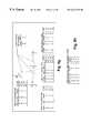
- FIG. 1is a block diagram of a mobile communication network having a plurality of nodes and incorporating a dynamic next hop routing protocol in accordance with the present invention
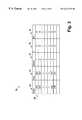
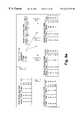
- FIG. 2is a diagram representing a routing table maintained in each of the network nodes in accordance with the present invention
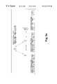
- FIG. 3is a flowchart representing overall operation of each node in the network in accordance with the present invention.
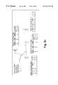
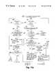
- FIG. 4is a flowchart representing the primary operation of each node in accordance with the present invention.
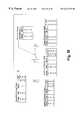
- FIGS. 5 a - 5 jillustrate an example of a router discovery process in the mobile communication network in accordance with the present invention
- FIGS. 6 a - 6 lillustrate an example of the present invention whereby the mobile communication network adapts for changes in topology among nodes;
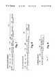
- FIG. 7represents an exemplary format of a router advertisement communicated between nodes in accordance with the present invention.
- FIG. 8is an exemplary format of a router solicitation exchanged between nodes in accordance with the present invention.
- FIG. 9is an exemplary format of a packet header in accordance with the present invention.
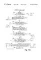
- FIG. 10is a flowchart representing a procedure whereby a node transmits a router advertisement identifying a list of other nodes which are reachable through its interface in accordance with the present invention
- FIGS. 11 a - 11 eis a flowchart illustrating a process in which a node updates its routing table in accordance with the present invention
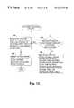
- FIG. 12is a flowchart illustrating a triggered update procedure carried out by each node to inform other nodes of changes in its routing table in accordance with the present invention
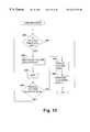
- FIG. 13is a flowchart representing a find neighbor routine in which each node solicits routing information from other nodes within a neighboring vicinity in accordance with the present invention
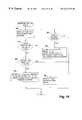
- FIG. 14is flowchart describing the process in which each node in the network maintains the routing information in its routing table in accordance with the present invention
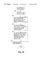
- FIGS. 15 a - 15 bis a flowchart representing the procedure whereby each node transmits and receives data packets in accordance with the present invention
- FIG. 16is a flowchart illustrating the manner in which each node refreshes routing information in its routing table in accordance with the present invention
- FIG. 17is a flowchart representing a procedure in which a router advertisement is transmitted periodically by each node in accordance with the present invention.
- FIG. 18is a block diagram of an exemplary mobile node in accordance with the present invention.
- an exemplary wireless communication network in accordance with the present inventionis generally designated as 20 .
- the network 20includes one or more devices 25 , also referred to herein as “nodes”. Each node is capable of wirelessly transmitting and receiving information via its respective antenna 26 .
- One or more of the nodes 25may be mobile devices (e.g., nodes 25 A, 25 B and 25 C) capable of movement throughout a geographical region.
- the mobile nodes 25 A- 25 Ccan be devices such as mobile data terminals, wireless telephones, personal pagers, etc. Each is portable and can be carried throughout the geographical region by a user.
- the network 20also includes one or more fixed nodes (e.g., nodes 25 D and 25 E) which are connected to a hardwired data communication path 27 .
- the hardwired data communication path 27may be made of twisted pair cable, shielded coaxial cable or fiber optic lines, for instance, and is generally referred to as a system backbone 27 .
- Each of the fixed nodes 25 D and 25 Ealso is capable of transmitting and receiving wireless communications involving other nodes 25 via its respective antenna 26 .
- nodes 25 D and 25 Eare able to communicate with other devices connected to the system backbone 27 using conventional network communication techniques.
- nodes 25 D and 25 Eare able to communicate with a host computer 30 which is also connected to the system backbone 27 .
- node 25 Afor example could also communicate with the host computer 30 through node 25 D.
- node 25 FAlso included in the network 20 is one or more fixed nodes (e.g., node 25 F) which serve primarily as a fixed location repeater station within the network 20 .
- node 25 Fmay serve as a communication link for communications between nodes 25 B and 25 E.
- fixed nodes within the network 20 that serve as repeatersfor example, it is possible to extend the geographical region of coverage of the network 20 as will be appreciated.
- each of the nodes 25includes a radio or other type of wireless transceiver for wirelessly transmitting and receiving information using conventional techniques.
- Each of the nodes 25is controlled by a processor which is programmed based on the flowcharts described herein in order to provide the routing for data packets which are wirelessly transmitted between nodes.
- the present inventionincludes the aspect whereby each of the nodes 25 maintains a routing table which includes a list of other nodes 25 in the network which are reachable through that node.
- a subject node 25receives a data packet for which it is not the ultimate destination, it looks up in its routing table the address of another node 25 which serves as the next hop in a communication link to the ultimate destination. The subject node 25 then forwards the data packet to the next node 25 .
- the nodes 25are mobile and their location may change over time, some nodes 25 may lose their respective communication links with other nodes 25 (e.g., such as by going out of range, encountering high noise conditions, etc.). Hence, the routing of information between nodes varies dynamically as existing links between nodes 25 may terminate and new links may be established.
- the present inventionincludes a protocol by which routing of data packets is carried out by maintaining in each node dynamic information regarding other nodes which are reachable therethrough.
- the present inventioncontemplates that at least one of the nodes 25 in the network 20 is mobile so as to provide optimum advantages. However, it will be appreciated that it is not necessary that any of the nodes 25 be mobile.
- FIG. 2represents a routing table 34 which each node 25 maintains in memory within the network 20 .
- the routing table 34 for a subject or given node 25includes entries for each of the other nodes 25 within the network 20 which are reachable through the subject node 25 .
- Each entryis represented by a row 36 and defines routing information for the corresponding node.
- IDnetwork identification address
- each entryincludes a “Hop” field 40 which includes the network ID of the particular node 25 which serves as the next hop (or “neighbor”) in a communication link between the subject node 25 and the node 25 identified in the “Node” field 38 .
- each entrycontains a “Metric” field 42 .
- the “Metric” field 42contains a metric associated with sending a data packet to the node 25 in field 38 via the subject node as discussed more fully below.
- a timeout field 44contains a timeout period used to determine whether the corresponding entry has been updated within a predefined period of time. If the timeout period in field 44 expires before the entry is updated, the entry is either marked unusable or is removed from the routing table 34 based on the value in the “Metric” field 42 as is described below in connection with FIG. 14 .
- each entry in the routing table 34includes a “Route Change (RC)” field 46 which is set when a new route is added or an existing route is changed.
- RCRecorde Change
- a route change flag in the RC field 46is set to “Y”. Otherwise, the flag in the RC field 46 is reset to “N”. Such information in the RC field 46 is used by the subject node 25 when performing a triggered update as is described more fully below in connection with FIG. 12 .
- the routing table 34 shown in FIG. 2may represent, for example, the routing table 34 for node 25 B as shown in FIG. 1 .
- the routing table 34includes entries for nodes 25 A, 25 D, 25 E and 25 F which have been found to be reachable either directly or indirectly via node 25 B.
- node 25 Bcan reach node 25 A directly as indicated by the entry for node 25 A.
- Node 25 Bcan reach node 25 D via node 25 A, and can reach node 25 E through node 25 F. Finally, the routing table 34 indicates that node 25 B can reach node 25 F directly. It is noted that the metrics in field 42 for the routes corresponding to nodes 25 A and 25 F are less than the metrics for the routes corresponding to nodes 25 D and 25 E since the direct links involve fewer “hops” among nodes and hence typically represent a communication link with a lower “cost”.
- step 60a node 25 executes a conventional self-initialization routine upon being powered up.
- the node 25then proceeds to step 62 in which it initializes its routing table 34 .
- the node 25is programmed to clear its routing table 34 .
- step 64the node 25 proceeds to step 64 in which it carries out primary operation as is described in detail below beginning with FIG. 4 .
- the node 25remains in step 64 until such time as it is powered down or is otherwise deactivated as represented in step 66 .
- FIG. 4is a flowchart representing the primary operation of each node 25 as embodied in step 64 of FIG. 3 .
- the operationcan be represented by four different subroutines 64 A- 64 D which are executed by the processor in each respective node 25 substantially simultaneously.
- Subroutine 64 Arelates to operations involving responding to router solicitations received from other nodes 25 , such router solicitations soliciting information regarding nodes which are reachable through the node.
- Subroutine 64 Binvolves operations in which a node 25 updates its routing table 34 in response to router advertisements received from other nodes 25 .
- each node 25is programmed to transmit a router advertisement periodically and in response to particular events including router solicitations received from other nodes 25 .
- a router advertisementincludes information regarding other nodes 25 which are reachable via the node 25 transmitting the router advertisement. Each node 25 utilizes such information to accumulate and update entries in its respective routing table 34 .
- Subroutine 64 Cinvolves a node 25 maintaining the contents of its routing table 34 .
- Subroutine 64 Drelates to the manner in which a node 25 receives and/or transmits data packets from/to other nodes 25 .
- step 70the subject node 25 determines if it has received a router solicitation from another node within the network.
- An exemplary format of a router solicitationis discussed below in connection with FIG. 8 .
- all router solicitationsare transmitted as multicast packets.
- a router solicitationis a request for recipient node(s) 25 to send a router advertisement to the source of the router solicitation.
- the router solicitationmay include a request for routing information for one or more specific nodes, or may be simply a request for all routing table entries from the recipient node(s) 25 .
- the subject node 25effectively loops through step 70 until a router solicitation is received.
- the subject node 25Upon receiving a router solicitation as determined in step 70 , the subject node 25 proceeds to step 72 in which the node 25 performs a routing table update as is described in detail below in connection with FIG. 11 . Since the subject node 25 received the router solicitation, there is known to exist a valid communication link between the source of the router solicitation and the subject node 25 . Hence, in step 72 the subject node 25 takes the opportunity to update its routing table 34 . This can include adding an entry to the routing table 34 corresponding to the source of the router solicitation. Following step 72 , the subject node 25 proceeds to step 74 in which it determines if there has been a change in its routing table. This is determined based on the entries in the RC field 46 of the routing table 34 as described more fully below.
- the node 25proceeds to step 76 in which it transmits a router advertisement in response to the router solicitation as discussed below in connection with FIG. 10 .
- the router advertisementin such case is a unicast packet transmitted to the source of the router solicitation identifying routing information for the particular nodes in the routing table of the subject node 25 which can be reached by the subject node 25 and which were identified in the router solicitation.
- the subject node 25returns to step 70 . If in step 74 it is determined that there has been a change in the routing table as a result of receiving the router solicitation, the node 25 proceeds to step 78 .
- the subject node 25performs what is referred to herein as a triggered update as is described in more detail below referring to FIG. 12 .
- the triggered updateinvolves the subject node 25 multicasting to any neighboring nodes a router advertisement which includes routing information for those nodes in the routing table 34 whose routing information has changed since the last router advertisement.
- the router advertisementincludes routing information for those route(s) requested in the router solicitation.
- each node 25responds to router solicitations received from other nodes by transmitting a router advertisement which includes information on the routes requested by the source of the router solicitation. In this manner, nodes 25 are able to educate their neighboring nodes as to which nodes are reachable through that particular node 25 .
- step 80the subject node 25 determines if a router advertisement has been received from any other nodes 25 .
- a router advertisementmay be in response to a router solicitation transmitted by the subject node 25 .
- the router advertisementmay be as a result of a periodic multicast or triggered update by another node as explained more fully below. If a router advertisement is not received, the subject node 25 will effectively continue to loop through step 80 as shown.
- the node 25Upon receiving a router advertisement as determined in step 80 , the node 25 proceeds to step 82 in which it updates the contents of its routing table 34 based on the information included in the router advertisement. As is discussed in more detail below in connection with FIG.
- the subject node 25utilizes the routing information included in the received router advertisement to add new routes and/or update existing routes in its routing table.
- the subject node 25determines if any changes occurred in its routing table 34 based on the route change flags in field 46 of the routing table 34 . If no, the node 25 returns to step 80 as shown. If yes, the node 25 proceeds to step 86 in which it carries out a triggered update in the same manner discussed above in connection with step 78 .
- the subject node 25informs its neighbors of any changes in its routing table 34 resulting from a routing advertisement.
- the neighboring nodesin turn, update their own respective routing tables 34 .
- the subject node 25returns to step 80 .
- Subroutine 64 Cbegins with step 90 in which the subject node 25 maintains its routing table 34 in the manner discussed more fully below in connection with FIG. 14 .
- step 90involves checking the timeout period in field 44 for each of the routing table entries to determine if the timeout period has expired since the last time the entry was updated. In this manner, communication links which were available at one time but may no longer be available are identified and cleared from the routing table 34 .
- the node 25proceeds to step 92 in which it determines if its routing table 34 is empty (indicating that no other nodes 25 are known to be reachable via the subject node 25 ).
- step 93the subject node 25 proceeds to step 93 in which it proceeds/continues to carry out a scheduled router advertisement routine in which router advertisements are multicasted periodically by the subject node 25 .
- the scheduled router advertisement routine of step 93is described more fully below in connection with FIG. 17 .
- the node 25returns to step 90 .
- step 92the subject node 25 determines that the routing table 34 is empty, the node 25 does not perform the scheduled periodic router advertisements of step 93 . Instead, the node 25 proceeds to step 94 in which it executes a find neighbor routine as is described below in relation to FIG. 13 .
- the subject node 25multicasts a router solicitation to any neighboring nodes 25 which are able to receive the router solicitation. In the router solicitation the subject node 25 requests that any neighboring nodes 25 provide information regarding nodes which are reachable therethrough. In this manner, the subject node 25 can “learn” any neighboring nodes 25 and other nodes 25 reachable therethrough, and other nodes can learn of the subject node. Following step 94 , the subject node returns to step 90 .
- Subroutines 64 A- 64 Cdeal primarily with routing protocol in accordance with the present invention.
- Subroutine 64 Drelates to the receipt/transmission of data packets by the subject node 25 based on the routing protocol. More specifically, subroutine 64 D involves the receipt/transmission of data packets which is carried out by the subject node 25 as part of its ordinary operation within the network 20 . For example, if the network 20 is used for keeping track of inventory or the like, such data which is transmitted or received in subroutine 64 D may be inventory data sent from one node 25 to another node 25 .
- Subroutine 64 Dconsists primarily of step 100 which is described in detail below in connection with FIGS. 15 a - 15 b . Step 100 involves the routing of data packets among the various nodes based on the routing information acquired in the routing table 34 of the subject node 25 as will be discussed.
- FIG. 5 aillustrates an example of a network which includes nodes A through D, each of nodes A through D being equivalent to nodes 25 discussed above. Shown in FIG. 5 a is the routing table 34 for each of the corresponding nodes. For purpose of clarity, routes for the various nodes themselves (i.e., loop-back routes) are shown in the corresponding routing tables and router advertisements in the following examples. However, these routes are ignored in the actual embodiment in order to reduce data traffic, and hence are shown with a metric value of zero in field 42 .
- FIG. 5 aassumes that a network is formed initially as shown with nodes A through D. All of nodes A through D are assumed to boot up or enter the network at approximately the same time with no previous state. Because of the range of the respective transceivers included within the nodes, assume nodes A, B and C are able to communicate directly with each other whereas node D can only communicate directly with node C. All routing tables are initialized and thus include only their respective loop-back route. Since the routing table of each of the nodes A through D is empty (i.e., includes only the respective loop-back route which is provided only for convenience), each of the nodes A through D enter a find neighbor state as represented in steps 92 and 94 in FIG. 4 .
- node Bis the first node to multicast a router solicitation to its neighbors (node A and node C) asking for all routes as part of node B's find neighbor routine in step 94 (FIG. 4 ). Since both nodes A and C do not have node B in their respective routing tables, node A and node C use the information in the router solicitation received from node B to add node B (with a metric of one) to their routing tables 34 as discussed above in connection with steps 70 and 72 (FIG. 4 ). The source of the router solicitation, i.e., node B, is identified as the next hop included in the next hop field 40 .
- Such change in the respective routing tables 34prompts node A and node C each to perform a triggered update as represented in step 78 (FIG. 4) and as is discussed below in connection with FIGS. 5 c and 5 d , respectively.
- triggered updates in step 78override unicast routing advertisements that node A and node C would otherwise send to node B in step 76 (FIG. 4) in response to the router solicitation from node B.
- node A and node Cnow have entries in their respective routing tables 34 (i.e., corresponding to node B)
- both nodestransition out of the find neighbor state of step 94 (FIG. 4) as discussed below.
- neither node A nor node Csends out its otherwise scheduled router solicitation.
- node Ais the first among nodes A and C to carry out its triggered update (step 78 ) in response to having added the route for node B to its routing table.
- Node Aas part of its triggered update, multicasts a router advertisement to its neighboring nodes (e.g., node B and node C).
- the router advertisementincludes all routing information from node A's routing table 34 (in response to node B's request for all routes), including route information corresponding to node B as provided from node A's routing table.
- node Abeing the source of the router advertisement, any nodes which receive the router advertisement are also able to ascertain routing information corresponding to node A. As shown in FIG.
- both node B and node Cadd route information for node A to their routing tables 34 as a result of receiving the router advertisement from node A (steps 80 and 82 in FIG. 4 ).
- both node B and node Cdiscard the route information for node B since they already have existing routes to B with a lower metric in their routing tables.
- the addition of the routing information for node A in the routing tables of nodes B and Cthen forces triggered updates from these nodes (steps 84 and 86 in FIG. 4 ), as represented in FIG. 5 d in the case of node C, for example.
- node B's and node C's routing information for node Aincludes node A in the next hop field 40 since it was the source of the router advertisement which resulted in the addition of node A to its routing table.
- a triggered updateforces node C to multicast a router advertisement to any neighboring nodes (e.g., nodes A, B and D).
- node Cincludes in the routing advertisement all routes in its routing table 34 .
- Nodes A and Badd routing information for node C to their respective routing tables in response to receiving the router advertisement (steps 80 , 82 in FIG. 4 ); however they discard the route information for nodes A and B since they both have existing routes to nodes A and B with a same or lower metric in their routing tables.
- Node Dadds routing information for each of the advertised nodes A, B and C since node D's routing table 34 is otherwise empty. This evokes triggered updates from each of nodes A, B and D since each of their respective routing tables have changed (steps 84 , 86 ).
- the triggered updatesinclude routing information relating to those nodes whose route change flags have been set indicating a change since their last routing advertisement.
- the route change flags in the routing tablesare reset after the updates are sent.
- the routing tables for nodes A and Bappear as shown in FIG. 5 e after their respective updates are sent.
- the triggered update by node Dcauses node D to multicast a router advertisement (steps 84 , 86 ) to its neighbors (e.g., node C), the router advertisement including routing information corresponding to nodes A through D (FIG. 5 f ).
- Node Creceives the router advertisement and adds node D to its routing table.
- node Cdiscards the route information for nodes A, B and C since it already has existing routes to these nodes with a lower metric in its routing table. This again evokes a triggered update from node C as represented in FIG. 5 g.
- the triggered updatecauses node C to multicast a router advertisement to its neighbors (e.g., nodes A, B and D) (steps 84 , 86 ). Since only route information corresponding to node D has been changed in node C's routing table, the router advertisement only includes an entry for node D. Nodes A and B receive the router advertisement and, since these nodes previously did not have node D in their routing tables, nodes A and B add node D to their routing tables. In this case, node C was the source of the router advertisement which resulted in the addition of node D. As a result, node C is identified in the next hop field 40 in connection with the node D entry in the routing tables of nodes A and B.
- neighborse.g., nodes A, B and D
- Node Dalso receives the router advertisement from node C. However, node D discards all the advertised routes as they already are included in node D's routing table with the same or lower metric.
- the triggered updates by nodes A and B resulting from the addition of the routing information for node Ddo not offer any new or lower cost routes to any of their neighbors. Consequently, they will have no affect on their neighbor's routing tables.
- the route change flags in field 46are reset after the updates are sent, and the routing tables for nodes A and B will appear as shown in FIGS. 5 h and 5 i , respectively. At this point, all of the routing tables for nodes A through D will have converged in the network to a steady state as represented in FIG. 5 j.
- FIGS. 6 a - 6 lillustrate an example where a node moves out of range of the others and another node is added to the network.
- FIG. 6 aassume that the network initially is in the steady state represented in FIG. 5 j discussed above.
- FIG. 6 aassume that node D roams out of range of its previous neighbor node C.
- Node Cdetects that the link to node D has failed either due to a delivery failure (see step 100 of FIG.
- Node Csets the metric for the route for node D to be “infinity” which, in the present embodiment, is a predetermined number such as “16”. More specifically, “infinity” as referred to herein is a metric whose value is one greater than the maximum number of hops allowed in the network.
- node Csets a delete timeout period for the node D route in field 44 as is described in more detail below in relation to FIG. 14 . This change in node C's routing table causes a triggered update to be sent from C as shown in FIG. 6 b .
- node Dall routes in the routing table of node D will timeout (step 90 ) such that their metrics are set to infinity and delete timeout periods are set.
- Such changes in node D's routing tablealso forces a triggered update from node D; however, no nodes are within range of node D to receive such update.
- the triggered update of node Ccauses the node to send a router advertisement to its neighbors (e.g., nodes A and B) indicating (by virtue of the metric equaling infinity) that node D can no longer be reached through node C.
- Nodes A and Bupdate their routing tables by setting the metric for the node D entry to infinity and by setting a delete timeout period in field 44 for node D.
- Such route updates in nodes A and Bcause these nodes to perform a triggered update. Since such triggered updates from nodes A and B offer no new or lower cost routes to any of their neighbors, they have no affect on their neighbors' routing tables.
- the route change flagsare reset after the updates are sent. This causes the routing tables for nodes A and B to appear as shown in FIG. 6 c following their respective updates.
- node Eenters the network and spans the gap between nodes C and D before the delete timeout periods in the routing tables for nodes A through D expire.
- the routing table of node Eis empty (i.e., only includes its loop-back route). Since node E's routing table is empty, node E enters its find neighbor state (steps 92 , 94 ) and multicasts a router solicitation to its neighbors requesting all routes as represented in FIG. 6 e .
- node Eis within range of nodes C and D. Nodes C and D will therefore receive the router solicitation.
- node ESince node E is not currently in the routing table of node C or node D, both node C and node D add node E to their respective routing table (steps 70 , 72 ). This causes nodes C and D to perform a triggered update (steps 74 , 78 ) as represented in FIGS. 6 f and 6 g , respectively.
- the triggered update by node Ccauses node C to multicast a router advertisement to its neighbors (nodes A, B and E).
- the router advertisementincludes all of the routes in C's routing table, not just the route which changed (node E). This is because it is combined with the response for all routes as solicited in the router solicitation from node E (step 78 ).
- Nodes A and Breceive the router advertisement (step 80 ) and add a route for node E in their respective routing tables (step 82 ). This in turn evokes triggered updates from nodes A and B (step 86 ).
- Node Eadds routes for nodes A, B and C to its routing table in response to the router advertisement from node C and in turn performs a triggered update (steps 80 - 86 ) as represented in FIG. 6 i . Note that node E does not add a route for node D from node C's router advertisement since its metric is set to infinity.
- FIG. 6 grepresents the triggered update by node D in response to the receipt of the router solicitation from node E and the addition of node E to its routing table (FIG. 6 e ).
- node Dmulticasts a router advertisement to its neighbors (e.g., node E) which includes all of the routes in node D's routing table since the router advertisement is in response to node E's solicitation for all routes.
- Node Ereceives the router advertisement and adds a route for node D based on the router advertisement.
- a triggered update(step 86 ) is initiated in node E.
- node Eignores the routes for nodes A, B and C as identified in the router advertisement from node D. This is because node E has valid routes to these nodes via another route (node C).
- a triggered updateis performed by node E in response to the changes in its routing table discussed above in relation to FIGS. 6 f and 6 g .
- node Emulticasts a router advertisement to its neighbors C and D (step 86 ) which includes recently added routes corresponding to nodes A through D.
- Node Creceives the router advertisement and updates its routing table by replacing the invalid route for node D with a route through node E, and ignores all other routes. This triggers an update from node C as discussed below in connection with FIG. 6 j .
- Node Dreceives the router advertisement from node E and replaces the invalid routes to nodes A, B and C with routes through node E, triggering an update from node D.
- FIG. 6 jrepresents the triggered update from node C in response to the router advertisement from node E.
- node Cmulticasts a router advertisement to its neighbors (e.g., nodes A, B and E).
- the router advertisementincludes the routing information relating to the newly changed route to node D.
- Nodes A and Bupdate their routing table replacing the invalid route to node D with a route through node C. This triggers an update from nodes A and B.
- Node Eignores the advertisement since no new or lower cost routes are offered. Since the resultant triggered updates by nodes A and B, together with the triggered update performed by node D in relation to FIG. 6 i , offer no new or lower cost routes to any of their neighbors, they have no affect on their neighbors' routing tables.
- the route change flagsare reset after the updates are sent.
- the routing tables for nodes A, B and D following their respective updatesappear as shown in FIG. 6 k .
- all of the routing tables of the respective nodes in the networkhave converged to a steady state as represented in FIG. 6 l .
- Data packetscan be sent between the nodes based on the information contained in the routing tables as is discussed more fully below.
- Each router advertisementis in the form of a packet which includes a header field 110 identifying the source and destination of the router advertisement as discussed below in connection with FIG. 9 .
- Adjacent the headeris a type field 112 which includes a predefined identifier which identifies the packet as relating to routing protocol so that the packet will be recognized as such by receiving nodes.
- a code field 114includes a predefined identifier indicating to any receiving nodes that the packet is a router advertisement.
- a version field 116includes a predefined identifier which identifies the particular version of routing protocol which is being carried out so that all nodes in the network employ the same version (provided multiple versions become available).
- a solicited identifier field 118is utilized in the event the router advertisement is being sent as a result of a router solicitation (e.g., in step 76 of FIG. 4 ). Specifically, each router solicitation also has a solicited identifier field 118 as discussed below in connection with FIG. 8 .
- the solicited identifier field 118contains a non-zero value identifying the particular router solicitation.
- Each node 25is programmed to increment the solicited identifier value with each router solicitation it transmits.
- the solicited identifier from the router solicitationis copied into the solicited identifier field 118 of the router advertisement. In this manner, the node 25 which transmitted the router solicitation can identify router advertisements in response thereto.
- the solicited identifier field 118is set to zero if the router advertisement is unsolicited (i.e., not in response to a router solicitation).
- the router advertisementalso includes an unsolicited identifier field 120 which is utilized in those cases where the router advertisement is sent out as a multicast (e.g., as part of a triggered or scheduled update in steps 78 , 86 , 94 and 100 ).
- the unsolicited identifier field 120includes a non-zero value which is incremented each time a node sends out an unsolicited router advertisement.
- the unsolicited identifier in field 120allows nodes 25 receiving the router advertisement to silently discard duplicate advertisements which can occur in an embodiment in which router advertisements are repeated in rapid succession. This may be desirable when communicating in a high bit error rate media.
- the router advertisementis a solicited advertisement (i.e., step 76 ) the unsolicited identifier field 120 is set to zero, with the exception that if the router advertisement is a triggered update resulting from a router solicitation (i.e., step 78 ), both the solicited and unsolicited identifier fields 118 and 120 are utilized.
- the router advertisementfurther includes a “number of routes” field 122 which is set by the sending node 25 and which identifies for the receiving node 25 the number of reachable nodes which will be specified in the router advertisement.
- the router advertisementincludes a link address field 124 which includes the link network addresses and the corresponding metrics of the reachable nodes as taken from the routing table 34 of the sending node 25 . For scheduled updates this will include all nodes identified in field 38 in the routing table. For triggered updates this will include all nodes whose route change flag is set in field 46 in the routing table. For a response to a router solicitation, this will include the nodes solicited and possibly those nodes whose route change flag is set.
- FIG. 8shows an exemplary format for the router solicitations transmitted by the nodes 25 .
- the router solicitationalso is in the form of a packet and includes a header 110 similar to that included in the router advertisement. Adjacent the header 110 is a type field 112 which, like the type field in the router advertisement, includes a predefined identifier which identifies the packet as relating to routing protocol so that the packet will be recognized as such by receiving nodes.
- a code field 114is also included in the router solicitation, but it contains a predefined identifier indicating to any receiving nodes that the packet is a router solicitation rather than a router advertisement.
- a version field 116 similar to that included in the router advertisementalso is included in the router solicitation.
- a solicited identifier field 118contains an identifier whose value uniquely identifies the particular router solicitation.
- a “number of routes” field 126is set to the number of nodes 25 which will be requested in the router solicitation. If a node wishes to request all routes from a receiving node, the “number of routes” field 126 is set to zero.
- a link address field 128includes the link addresses of the specific nodes for which routes are solicited. If the number of routes field 126 is set to zero, the link address field 128 is excluded.
- FIG. 9illustrates an exemplary header field 110 for use in accordance with the invention.
- the header field 110is utilized in the router advertisement and solicitation packets as noted above as well as with any data packets which are transmitted within the network.
- the header field 110includes a source field 130 which identifies the immediate source node of the packet.
- the header field 110includes a destination field 132 which identifies the immediate destination node of the packet. If the packet is to be multicasted, the destination field 132 is set all “1's”.
- the header field 110also includes an ultimate source field 134 that identifies the ultimate source node of the packet, namely the node from which the packet originated.
- the header 110includes an ultimate destination field 136 that identifies the ultimate destination node of the packet, i.e., where the packet is ultimately intended to go.
- the ultimate source field 134 and ultimate destination field 136are utilized only in the case of data packets where the packets may be forwarded.
- the ultimate source field 134 and ultimate destination field 136remain unused in router advertisements and router solicitations which are not forwarded.
- each node 25includes a processor which is programmed to transmit and receive packets according to the formats shown in FIGS. 7-9. More specifically, the processor is programmed to insert the appropriate information in the respective fields depending on the circumstances as will be appreciated.
- a node 25returns a router advertisement in response to a router solicitation as represented in step 76 of FIG. 4 .
- the node 25is programmed to begin generating a router advertisement.
- the node 25sets the type field 112 to represent a routing protocol packet.
- the code field 114is set to indicate a router advertisement.
- the version field 116is set to represent a particular version assumed to be the same throughout the present embodiment.
- the source field 130is set to identify the node 25 which is transmitting the router advertisement.
- the destination field 132is copied from the source field 130 of the router solicitation which prompted the router advertisement so as to indicate that the router advertisement is intended for the node 25 which sent the router solicitation. In other situations where the router advertisement is intended to be multicasted, however, the destination field 132 is set to all “1's”. The ultimate source and destination fields 134 and 136 are unused as indicated above.
- step 142the solicited identifier from field 118 of the router solicitation is copied to the solicited identifier field 118 of the router advertisement.
- the unsolicited identifier in field 120is set to zero since the router advertisement is solicited.
- step 144the number of routes field 122 is set to indicate the number of reachable nodes which will be specified in the router advertisement.
- step 146the link addresses and corresponding metrics of the reachable nodes which are included in the routing table 34 of the node 25 and which are solicited in the router solicitation are included in the link address field 124 . To the extent that the routes solicited include the subject node itself, it is not necessary that the route for the subject node be included in the link address field 124 . Such information is ascertained from the source field 130 of the router advertisement itself as discussed below in FIG. 11 .
- step 148the node 25 transmits the router advertisement to the node which issued the router solicitation.
- FIG. 11 a - 11 erepresent the procedure in which a node 25 updates its routing table 34 as represented in steps 80 and 82 in FIG. 4 .
- the node 25determines if the routing table is being updated in response to a router advertisement (e.g., step 82 ). If yes, the node 25 proceeds to step 152 in which it begins the process of reviewing the contents of the router advertisement and updating its routing table 34 based thereon. Specifically, the node 25 looks both to the source field 130 of the router advertisement and to each of the link addresses included in the link address field 124 , although one at a time, to determine if new or lower cost routes are available in the router advertisement.
- the node 25selects, for example, the source node of the router advertisement (or the next link address in the link address field 124 ). Then, in step 154 the node 25 determines if the advertised metric of the selected source node or link address node is less than infinity (e.g., “16”). It is noted that in the case of the source node represented in the source field 130 of the router advertisement, the metric is predetermined to be “0” since router advertisements are received only directly from the source node.
- the node 25proceeds to step 156 in which the advertised metric is modified to include the cost of the hop on which the router advertisement was received.
- the advertised metricis modified to include the cost of the hop on which the router advertisement was received.
- thiswill involve incrementing the advertised metric by one to indicate the added cost of one hop.
- different criteriamay be utilized in different embodiments for determining the added cost.
- the amount by which the advertised metric is modifiedmay take into consideration such things as traffic load, etc.
- a node which is incurring heavy data trafficmay increment an advertised metric by more than one so as to discourage other nodes from using such node as a link.
- the cost associated with one hopmay be greater than one under different conditions such as when a node has two radios (e.g., LAN and WAN, or 2.4 GHz and 900 MHz. In such case a higher cost would be associated with hops over the slower medium.
- two radiose.g., LAN and WAN, or 2.4 GHz and 900 MHz. In such case a higher cost would be associated with hops over the slower medium.
- the node 25proceeds to step 158 in which it determines if the selected source/link address node already exists as an entry in the node's routing table 34 . If yes, the node 25 continues to step 160 in which it determines if the source of the router advertisement (as determined from the source field 130 ) is the same as the node identified in the next hop field 40 (FIG. 2) for that entry. If no in step 160 , the node 25 proceeds to step 162 in which the node 25 determines if the modified metric for the selected source/link address node is less than the metric already included in the routing table entry.
- step 162the node 25 continues to step 164 in which it replaces the existing route with the advertised route and sets the route change flag if necessary. More specifically, for the selected source node/link address which already exists in the node field 38 (FIG. 2 ), the next hop field 40 is set with the source node from the router advertisement as obtained from the source field 130 . The metric field 42 is set with the updated metric as determined in step 156 . Finally, the route change flag in field 46 is set to “Y” if the updated metric is different from the previous metric. The node 25 then proceeds from step 164 to step 166 in which the timeout period in field 44 of the routing table 34 is set for the modified entry.
- Step 166involves a route refresh routine which is described in more detail below in relation to FIG. 16 .
- the timeout period in field 44 for the modified entryis set to a predetermined time equal to ROUTE_ADVER_TIME ⁇ 3, where ROUTE_ADVER_TIME is equal to the time interval (e.g., 10 seconds) between scheduled router advertisement updates as discussed below in connection with FIG. 17 .
- the node 25proceeds to step 168 where it determines if any source/link address nodes remain from the router advertisement which have not yet been processed. If yes in step 168 , the node 25 returns to step 152 where the next node from the router advertisement is selected. If no nodes remain as determined in step 168 , the node 25 proceeds to step 170 in which the routing table update routine is completed.
- step 158the selected source/link address node is determined not to exist already in the routing table 34 , the node 25 proceeds to step 178 as shown in FIGS. 11 a - 11 c .
- step 178the node 25 determines if the selected source/link address node has a modified metric which is less than infinity. If yes, the selected source/link address node is added as an entry to the routing table 34 . Specifically, the selected node is added as an entry in node field 38 and the remainder of the corresponding fields are set as follows.
- the next hop field 40is set with the source node which generated the router advertisement as obtained from the source field 130 .
- the metric field 42is set with the modified metric as determined in step 156 .
- the timeout period in field 44is reset to a predetermined time period such as ROUTE_ADVER_TIME ⁇ 3.
- the route change flag in field 46is set to “Y”. If the modified metric as determined in step 156 is equal to or greater than infinity, the route corresponding to the selected node is not added as it is considered to represent an invalid route and the node 25 proceeds directly from step 178 to step 168 . Following step 180 , the node 25 goes to step 168 as noted above to determine if any additional nodes remain from the router advertisement.
- the subject node 25proceeds directly from step 160 to step 164 .
- the existing route for the selected source/link address nodeis replaced in the routing table 34 regardless of the advertised metric value. This is because the previous route may no longer exist.
- the node 25then carries out steps 164 and 166 in the manner discussed above in order to update the entry in the routing table.
- step 162it may be the case that the modified metric for the selected source/link address node is not less than the metric in the existing routing table entry. Hence, the advertised route does not offer a lower cost alternative route. As a result, the node 25 proceeds from step 162 to step 188 in which the node 25 ignores the route information for the selected source/link address node. Following step 188 , the node 25 proceeds to step 168 to determine if any other nodes remain from the router advertisement.
- the advertised metric of the selected source/link address nodemay be equal to infinity (as in the case of an invalid link). If so, the node 25 proceeds from step 154 to step 190 .
- the node 25determines if the selected source/link address node already exists in the routing table 34 . If not, the node 25 proceeds to step 168 where it discards the selected source/link address node as the route is invalid and determines if any nodes remain in the router advertisement. However, if the selected source/link address node does exist in the routing table as determined in step 190 , the node 25 proceeds to step 192 .
- step 192the node 25 determines if the source node of the router advertisement (as determined from field 130 ) is the same as the node identified in the next hop field 40 in the existing routing table entry for the selected source/link address node. If no, the node 25 proceeds directly from step 192 to step 168 .
- step 192the node 25 thereby knows that the existing route in the routing table for the selected source/link address node is no longer valid. Consequently, the node 25 proceeds to step 194 in which it changes the metric in field 42 of the existing entry to infinity. In addition, the route change flag in field 46 is set to “Y” to indicate that the route has changed. Following step 194 , the node 25 continues to step 196 in which the route refresh routine mentioned in step 166 is carried out.
- the timeout period in field 44 for the selected source/link address nodeis set in the routing table to be equal to a predetermined delete timeout period such as ROUTE_ADVER_TIME ⁇ 2.
- the node 25proceeds to step 168 to determine if any additional nodes exist in the router advertisement which need to be processed in the manner described above.
- step 200determines in step 200 whether the update has been initiated in response to a router solicitation (e.g., step 72 in FIG. 4 ). If the node 25 concludes that the routing table update has not been initiated in response to a router solicitation, an error occurs as shown in step 202 . This is because in the exemplary embodiment a routing table update is intended to be performed only in response to a router advertisement or a router solicitation.
- the node 25proceeds to step 204 where it determines if the source node of the router solicitation already exists as an entry in its routing table 34 . Specifically, the node 25 compares the node identified in field 130 of the router solicitation with the nodes identified in fields 38 of the routing table 34 . If no, the node 25 proceeds to step 206 in which it adds the source node from field 130 as an entry in the routing table 34 .
- the source node from field 130is copied into a new field 38 in the routing table 34 .
- the source node from field 130also is copied into the corresponding next hop field 40 since the same node serves as a link to itself.
- the metric in field 42is set to a predetermined minimum value, e.g., “1” representing the cost of one hop.
- the timeout period in field 44is set to a predetermined value, e.g., ROUTE_ADVER_TIME ⁇ 3.
- the route change flag in field 46is set to “Y”. Following step 206 , the node 25 proceeds to step 170 where the routing table update is completed.
- step 204the node 25 determines that the source node already exists in the routing table 34 , the node 25 proceeds to step 208 in which the metric for the existing entry in field 42 is compared with the predefined metric (e.g., “1”) associated with a source node of a router solicitation. If the metric for the existing entry is equal to the predefined metric, the node ignores the new route information and proceeds to step 170 . On the other hand, if the metric of the existing entry is less than or greater than the predefined metric, the node 25 proceeds to step 210 in which the existing entry is updated to include the new cost of the route. In particular, the next hop field 40 is set to include the source node itself.
- the predefined metrice.g., “1”
- the metric in field 40is set to the predefined metric (e.g., “1”).
- the timeout period in field 44is set to ROUTE_ADVER_TIME ⁇ 3, and the route change flag in field 46 is set to “Y”.
- the node 25proceeds to step 170 where the update of the routing table is completed.
- each node 25performs a triggered update.
- the node 25determines if the triggered update is being performed in response to receipt of a router solicitation (i.e., step 78 in FIG. 4 ). If yes, the node 25 proceeds to step 222 in which it generates and multicasts a router advertisement.
- the router advertisementincludes routes for those entries in its routing table 34 whose route change flag in field 46 is set to “Y”, and any route(s) requested in the link address field 128 of the router solicitation for which there is an entry in the routing table 34 or which represent the node 25 itself.
- the specific procedure for generating the router advertisementis similar to steps 140 - 146 discussed above in connection with FIG.
- the router advertisementincludes any other routes in its routing table 34 which have their route change flags set. Moreover, since the router advertisement is being multicast the unsolicited identifier in field 120 is also included in the router advertisement in step 222 . In addition, the destination field 132 for the router advertisement is set to all “1's” to indicate a multicast. Following step 222 , the node 25 proceeds to step 224 in which it resets all of the route change flags in field 46 of the routing table from “Y” to “N”. After step 224 , the triggered update is completed.
- step 220the node 25 determines that the triggered update is not in response to receipt of a router solicitation, the node 25 proceeds instead to step 226 .
- step 226the node generates and multicasts a router advertisement which includes only those routes corresponding to entries in its routing table 34 which have their route change flag set to “Y”.
- the router advertisementis generated in the same manner as in step 222 with the exception that the router advertisement does not include a solicited identifier in field 118 and the field is set to zero.
- the link address field 124includes only those entries whose route change flag is set.
- step 224the node 25 proceeds to step 224 in which the route change flags for the respective entries are reset. From step 224 the triggered update is completed.
- FIG. 13illustrates in detail the find neighbor routine carried out by each node 25 in step 94 (FIG. 4 ).
- the node 25checks whether its routing table 34 is still empty. This is done in case a routing table entry was added since step 92 (FIG. 4) due to, for example, receipt of a router solicitation as exemplified in FIG. 5 b above.
- the node 25proceeds to step 232 in which it generates and multicasts a router solicitation requesting all routes.
- the node 25forms a router solicitation packet of the type shown in FIG. 8 .
- the source field 130is set to include the node 25 which is transmitting the router solicitation.
- the destination field 132is set to all “1's” to indicate a multicast.
- the ultimate source and destination fields 134 and 136are not used as previously indicated.
- the type field 112is set to indicate that the packet relates to routing protocol.
- the code field 114is set to indicate that the packet is a router solicitation, and the version field 116 is set to include the proper version information.
- the solicited identifier field 118is completed with the incremented solicited identifier value which identifies the particular router solicitation.
- the number of routes field 126is set to zero to indicate to all receiving nodes 25 that all available routes from their respective routing tables are requested.
- the link address field 128is excluded as the node 25 seeks any and all routes rather than specific route(s).
- the node 25Upon transmitting the router solicitation in step 232 , the node 25 proceeds to step 234 in which it waits a predetermined period (e.g., 5 seconds) to receive any router advertisements in response to its solicitation. In step 236 , the node determines if it has received any router advertisements. If yes, the node 25 proceeds to step 238 in which it updates its routing table in the manner described above in connection with FIG. 11 a - 11 e Following step 238 , the node 25 performs a triggered update in step 240 with respect to each router advertisement in the manner described above in relation to FIG. 12 . In this way, the node 25 is able to add one or more entries to its routing table 34 and the find neighbor procedure is completed.
- a predetermined periode.g., 5 seconds
- step 236the node 25 determines that it has not received a router advertisement
- the node 25returns to step 230 in which it checks if its routing table 34 remains empty. If no, indicating that an entry was added as a result of the node receiving a router solicitation, for example, the node 25 completes the find neighbor procedure as shown. Otherwise, if the routing table 34 is still empty the above-described process is repeated until such time as one or more routes are added to the routing table 34 .
- step 232is repeated every ROUTE_ADVER_TIME seconds until such time as one or more entries exist in the routing table.
- FIG. 14illustrates the procedure by which a node 25 maintains its routing table as represented in step 90 of FIG. 4 .
- the procedureis shown as a single step in FIG. 4, it will be appreciated that the procedure is carried out substantially continuously by the node 25 .
- the node 25monitors the timeout periods in field 44 for each of the respective entries in its routing table 34 .
- the timeout periods in field 44 for each of the entriescontinues to run as determined by a clock (not shown) included in the node 25 .
- the timeout periodsrun down until such time as they are reset or expire.
- the node 25continues to monitor the respective timeout periods.
- the node 25determines if any of the timeout periods have expired.
- step 254it checks whether the metric for any entry which has expired is less than infinity. If no, that indicates that the expired entry has already been identified as representing an invalid route. Hence, the node 25 proceeds to step 256 in which the entry is deleted from the routing table 34 . If in step 254 the metric for an expired entry is less than infinity, this indicates that the particular entry only recently has become invalid. As a result, rather than immediately clearing the entry from the routing table 34 the node 25 proceeds to step 258 in which the metric for the expired entry is set to infinity together with the metrics for any entries in which the expired entry is identified in the next hop field 40 .
- the timeout period in field 44 for the expired entry and any other entries in which the expired entry is identified in the next hop field 40is reset to a delete timeout period of ROUTE_ADVER_TIME ⁇ 2; and the route change flags in field 46 is set to “Y”. Thereafter, the node 25 performs a triggered update to inform its neighbors of the changes in its routing table.
- step 252determines if the node 25 determines that none of the timeout periods have expired, it proceeds to step 260 in which it determines if an error message has been received in connection with the transmission of data packets as discussed below in relation to FIGS. 15 a - 15 b .
- Such error messagesindicate that a data packet was sent unsuccessfully to a node according to a route included in the routing table 34 . If such an error message is received as determined in step 260 , the node 25 proceeds to step 262 .
- the metric for the node to which the data packet was unsuccessfully directedis set to infinity together with the metrics for any entries which have the node to which the packet was directed in their next hop field 40 .
- the timeout period in field 44is set to ROUTE_ADVER_TIME ⁇ 2; and the route change flag in field 46 is set to “Y” for the respective nodes.
- the node 25performs a triggered update to inform its neighbors of the changes in its routing table.
- the process in FIG. 14is continuously repeated in effect such that the information in the routing table 34 remains current.
- FIGS. 15 a - 15 brelates to the receipt/transmission of data packets as carried out by each node 25 (step 100 of FIG. 4 ).
- Data packetsinclude a standard header 110 as represented in FIG. 9 together with a data field (not shown).
- the node 25determines if a data packet has been received by the node. If no, the node 25 proceeds to step 282 in which it determines if the node 25 needs to transmit a data packet (e.g., as part of its normal operations). If no, the node 25 returns to step 280 . If yes, the node 25 proceeds to step 283 in which it determines whether route information for the node to which the packet is ultimately destined exists in its routing table 34 .
- the node 25proceeds to steps 324 through 330 as discussed below in order to solicit routing information for the ultimate destination node from its neighboring nodes. Otherwise, the node 25 proceeds from step 283 to step 284 in which it generates a packet including a header 110 .
- the source field 130 and the ultimate source field 134are set to contain the address of the subject node 25 itself.
- the destination field 132is set to include the node identified in the next hop field 40 of the entry corresponding to the ultimate destination node in the routing table 34 .
- the ultimate destination node 136is set to include the address of the node to which the packet is ultimately directed.
- the data field(not shown) is completed with the appropriate data which is desired to be transmitted.
- the subject node 25transmits the thus formed data packet in step 286 .
- the node 25determines if a receipt acknowledgment has been received indicating that the packet was successfully received by the node identified as being the next hop in field 132 .
- each of the nodes 25are configured to transmit a receipt acknowledgment according to conventional techniques so as to indicate to the source node whether a data packet was received. If a receipt acknowledgment is received in step 288 , the subject node 25 returns to step 280 .
- step 288If in step 288 a receipt acknowledgment is not received indicating a broken communication link between the subject node 25 and the destination node identified in field 132 , the subject node 25 proceeds to step 290 .
- step 290the node 25 sets the metric in its routing table 34 for the entry corresponding to the destination node in field 132 to infinity. It is noted that since the destination node in field 132 serves as a next hop node for the ultimate destination node in field 136 based on the routing table 34 , the routing table 34 will necessarily include an entry for the node identified in field 132 since such node will have served as the basis for the route information (see, e.g., FIGS. 11 a - 11 e ).
- the subject node 25sets the metrics to infinity for any other “related” entries in its routing table 34 which have the destination node identified in field 132 as the next hop in field 40 of its routing table 34 .
- the subject node 25 in step 290also sets the metric for the entry corresponding to the ultimate destination node to infinity.
- the node 25sets the route change flag(s) in field 46 to “Y” and sets the timeout period(s) in field 44 to ROUTE_ADVER_TIME ⁇ 2 for the respective entry(ies) which have been changed.
- step 292the node 25 carries out a triggered update as described above in order to inform its neighbors of the recently discovered invalid communication links.
- the subject node 25then waits a predetermined amount of time in step 294 to allow the triggered updates to cascade through the network. This is to avoid having a neighbor falsely advertise that it can reach the desired node via the node where the link had just failed. Such time can be on the order of 10 seconds, for example.
- step 294the subject node 25 proceeds to step 296 in which it multicasts a router solicitation in an attempt to learn of a possible new route(s) to the desired destination node(s).
- the node 25identifies in the link address field 128 the particular nodes for which the metric in its routing table were set to infinity in step 290 .
- the router solicitationis multicasted in step 296 and in step 298 the node 25 waits to receive router advertisements in response to the solicitation. Provided any router advertisements are received indicating alternate route(s), the node 25 updates its routing table and performs a triggered update in step 298 in the manner described above.
- the node 25proceeds to step 300 in which it determines if a valid route to-the desired ultimate destination node exists in its routing table 34 . If yes, the node 25 updates the header information in step 302 to indicate the new next hop node in field 132 . The node 25 then returns to step 286 where it retransmits the data packet and the above-described procedure is repeated. If a valid route to the ultimate destination node does not exist as determined in step 300 , the node 25 goes to step 304 . In step 304 the node 25 transmits an error message directed to the ultimate source node identified in field 134 of the data packet indicating that it was unable to deliver the data packet.
- the subject node 25is the ultimate source node (i.e., the transmit data originates from the subject node 25 (“Yes” in step 282 )), such step is unnecessary as will be appreciated.
- the subject node 25is serving as an intermediate node (as described below) for purposes of forwarding a data packet, such error message is transmitted in step 304 to the ultimate source node.
- the ultimate source nodeuses such error message to update its routing table in relation to the invalid link (steps 260 , 262 in FIG. 14 ).
- step 310if it is determined by the node 25 that a data packet has been received, the node 25 proceeds to step 310 .
- the node 25 in step 310generates and transmits a receipt acknowledgment to the node identified as the immediate source in field 130 of the data packet.
- step 312the node 25 determines if the node 25 itself is the ultimate destination node for the data packet as identified in field 136 . If yes, the data packet is intended for the subject node 25 and the node proceeds to step. 314 in which it processes the data in the packet for its intended purpose (e.g., inventory tracking, etc.).
- the node 25proceeds from step 312 to step 316 in which it determines if the ultimate destination node in field 136 exists as an entry in its routing table 34 . If yes, the node 25 proceeds to step 318 in which it simply updates the data packet by inserting into the destination field 132 the next hop node associated with the ultimate destination node from the routing table in field 40 . In addition, the node 25 identifies itself in the source field 130 . Following step 318 , the node 25 goes to step 286 where the revised data packet is transmitted in accordance with the steps. previously described above. Thus, the data packet is forwarded by the subject node 25 .
- step 316the node 25 proceeds to step 324 .
- step 283the ultimate destination node does not exist in the subject node's routing table the node 25 proceeds to step 324 .
- step 324the node 25 generates and multicasts a router solicitation in step 324 seeking routes to the ultimate destination node.
- the node 25then waits in step 326 for a predetermined period of time (e.g., 5 seconds) to receive any router advertisements which result from the router solicitation.
- step 328the node 25 updates its routing table and performs a triggered update if appropriate based on any router advertisements which were received.
- the node 25then goes to step 330 in which it determines if the ultimate destination node represented in field 136 of the data packet now exists in the routing table 34 . If not, the node 25 proceeds to step 304 in which it transmits an error message to the ultimate source node (unless the node 25 is itself the ultimate source node) to inform the ultimate source node that the node 25 was unable to forward/transmit the packet. In the event the ultimate destination node 25 does now exist in the routing table as determined in step 330 , the node 25 proceeds to step 332 in which it determines whether the routing information recently obtained in steps 324 - 330 was based originally on a transmit data function (“No” in step 283 ) or a receive data function (“No” in step 316 ).
- step 31 8If based originally on a receive data function, the node proceeds to step 31 8 in which it updates the data packet to be forwarded in the manner described above in order that it can be forwarded to the next hop along the communication link. If in step 332 it is determined the recently obtained routing information was acquired in connection with an original transmit function, the node 25 then proceeds to step 284 where it goes about generating the packet to be sent with the appropriate header information and the data to be transmitted.
- the process by which routes are refreshede.g., steps 166 , 196 in FIGS. 11 a - 11 b is shown.
- the node 25checks whether the route being refreshed has a metric which is valid (i.e., less than infinity). If yes, the timeout period for the particular entry is set to ROUTE_ADVER_TIME ⁇ 3 as represented in step 352 . On the other hand, if the metric is invalid (i.e., infinity or greater), the timeout period in field 44 is set to ROUTE_ADVER_TIME ⁇ 2 as shown in step 354 .
- the routine for sending scheduled router advertisements(step 93 in FIG. 4) is shown.
- the node 25is programmed to multicast router advertisements every ROUTE_ADVER_TIME seconds (e.g., 10 seconds).
- Such router advertisementsinclude routes for all valid entries in the routing table regardless of whether the corresponding route change flag is set.
- the route change flag for each of the entriesis reset to “N”.
- Each mobile node 25includes a processor 370 which can be programmed to control and to operate the various components within the mobile node 25 in order to carry out the various steps and functions described herein.
- the processor 370is coupled to an operator input device 372 which allows an operator to input data to be communicated to another node such as inventory data, patient information, etc. This information may be sent ultimately to the host computer 30 (FIG. 1) which serves as a central data location, for example.
- the input device 372can include such items as a keypad, touch sensitive display, etc.
- the mobile node 25also may include a bar code scanner 373 coupled to the processor 370 for providing another form of data input.
- a display 374is also connected to and controlled by the processor 370 via a display driver circuit 375 .
- the display 374serves as a means for displaying information stored within the mobile node 25 .
- the display 374can be a flat panel liquid crystal display with alphanumeric capabilities, for example, or any other type of display as will be appreciated.
- a memory 376is included in each mobile node 25 for storing program code executed by the processor 370 for carrying out the functions described herein.
- the actual code for performing such functionscould be easily programmed by a person having ordinary skill in the art of computer programming in any of a number of conventional programming languages based on the disclosure herein. Consequently, further detail as to the particular code has been omitted for sake of brevity.
- the memory 376also serves as a storage medium for storing packets received from or intended to be transmitted to other nodes 25 as discussed herein. Moreover, the memory 376 serves as a storage location for storing the routing table 34 corresponding to the node 25 .
- Each mobile nodealso includes its own RF section 378 connected to the processor 170 .
- the RF section 378includes an RF receiver 382 which receives RF transmissions (e.g., router advertisements, router solicitations, data packets, etc.) from other nodes via its antenna 26 and demodulates the signal to obtain the digital information modulated therein.
- RF transmissionse.g., router advertisements, router solicitations, data packets, etc.
- An example of a suitable RF receiver 382 for use in the mobile node 25is the Model O 25 Direct Sequence Spread Spectrum Radio Module, which is commercially available from Aironet Wireless Communications, Inc. of Akron, Ohio.
- the RF section 378also includes an RF transmitter 386 .
- the processor 370forms within the memory 376 an appropriated packet in the manner described above. The packet is then delivered to the RF transmitter 386 which transmits an RF signal with the packet modulated thereon via the antenna 26 according to conventional techniques.
- a fixed node 25(e.g., nodes 25 D and 25 E in FIG. 1) is similar to the mobile node 25 shown in FIG. 17, but may include a hardwired connection to the system backbone 27 for example. Also, depending on what extent the fixed node 25 is to be used for allowing user input versus simply serving to route data packets, the fixed node 25 may omit the display, bar code scanner, etc. In the case of the fixed node 25 F, for example, there is no connection to the system backbone 27 .
- the present inventionprovides a network in which the nodes themselves are the routers of data packets.
- the nodesadvertise a list of nodes which are reachable through their interface(s).
- a nodereceives a data packet for which it is not the ultimate destination, it looks up the next hop link address from its list of reachable nodes, and forwards the data packet to that address.
Landscapes
- Engineering & Computer Science (AREA)
- Computer Networks & Wireless Communication (AREA)
- Signal Processing (AREA)
- Data Exchanges In Wide-Area Networks (AREA)
- Mobile Radio Communication Systems (AREA)
Abstract
Description
Claims (34)
Priority Applications (1)
| Application Number | Priority Date | Filing Date | Title |
|---|---|---|---|
| US08/741,208US6421731B1 (en) | 1996-10-29 | 1996-10-29 | Dynamic next hop routing protocol |
Applications Claiming Priority (1)
| Application Number | Priority Date | Filing Date | Title |
|---|---|---|---|
| US08/741,208US6421731B1 (en) | 1996-10-29 | 1996-10-29 | Dynamic next hop routing protocol |
Publications (1)
| Publication Number | Publication Date |
|---|---|
| US6421731B1true US6421731B1 (en) | 2002-07-16 |
Family
ID=24979795
Family Applications (1)
| Application Number | Title | Priority Date | Filing Date |
|---|---|---|---|
| US08/741,208Expired - LifetimeUS6421731B1 (en) | 1996-10-29 | 1996-10-29 | Dynamic next hop routing protocol |
Country Status (1)
| Country | Link |
|---|---|
| US (1) | US6421731B1 (en) |
Cited By (97)
| Publication number | Priority date | Publication date | Assignee | Title |
|---|---|---|---|---|
| US20020025817A1 (en)* | 2000-08-25 | 2002-02-28 | Shuichi Karino | Route updating method for micromobility network |
| US20020087703A1 (en)* | 2000-12-29 | 2002-07-04 | Waldemar Wojtkiewicz | Autodetection of routing protocol version and type |
| US20020087659A1 (en)* | 2000-10-18 | 2002-07-04 | Chapman Alan S. | Content networks |
| US20020107023A1 (en)* | 2000-12-29 | 2002-08-08 | Chari Amalavoyal Narasimha | Method and apparatus to provide a routing protocol for wireless devices |
| US20020154607A1 (en)* | 2001-02-13 | 2002-10-24 | Nokia Corporation | Short range RF network configuration |
| US6567380B1 (en)* | 1999-06-30 | 2003-05-20 | Cisco Technology, Inc. | Technique for selective routing updates |
| US6577634B1 (en)* | 1998-07-01 | 2003-06-10 | Hitachi, Ltd. | Method for sharing network information and a router apparatus |
| US20030112799A1 (en)* | 2001-11-17 | 2003-06-19 | Ravi Chandra | Method and apparatus for multiple contexts and layer 3 virtual private networks |
| US20030118009A1 (en)* | 2001-11-09 | 2003-06-26 | Klaus Hoffmann | Provision of IVR resources in BICC networks |
| US6611499B1 (en)* | 1999-03-18 | 2003-08-26 | At&T Corp. | Method for measuring the availability of router-based connectionless networks |
| US6622005B1 (en)* | 2000-03-03 | 2003-09-16 | Ericsson Inc. | Methods, systems and devices for cascaded communications |
| US20040014467A1 (en)* | 2000-10-26 | 2004-01-22 | O'neill Alan W | Telecommunications routing |
| US20040039831A1 (en)* | 2000-07-14 | 2004-02-26 | Jochen Grimminger | Method and arrangements for router advertisement in a network with mobile anchor points |
| US6717919B1 (en)* | 1999-11-23 | 2004-04-06 | 3Com Corporation | Imprinting method for automated registration and configuration of network devices |
| US20040093426A1 (en)* | 2002-11-07 | 2004-05-13 | Nokia Corporation | System and method for mobile router cost metric updates for routing protocols |
| US20040113810A1 (en)* | 2002-06-28 | 2004-06-17 | Mason Robert T. | Data collector for an automated meter reading system |
| US20040213218A1 (en)* | 1999-09-08 | 2004-10-28 | Qwest Communications International Inc. | System and method for dynamic distributed communication |
| US6816706B1 (en) | 1999-09-08 | 2004-11-09 | Qwest Communications International, Inc. | Wireless communication access point |
| US6831902B1 (en) | 1999-09-08 | 2004-12-14 | Qwest Communications International, Inc. | Routing information packets in a distributed network |
| US20040264379A1 (en)* | 2000-12-29 | 2004-12-30 | Devabhaktuni Srikrishna | Multi-channel mesh network |
| US20050044217A1 (en)* | 1999-08-26 | 2005-02-24 | Canon Europa N.V. | Device and method for discovering peripherals connected to a computer network |
| US20050234768A1 (en)* | 2002-09-18 | 2005-10-20 | Stephanie Wald | System for multimedia viewing based on entitlements |
| US7007100B1 (en)* | 2000-12-20 | 2006-02-28 | Nortel Networks Limited | Method for synchronization of multicast routing table changes with a plurality of multicast routing protocols |
| US20060067232A1 (en)* | 2004-09-24 | 2006-03-30 | Samsung Electronics Co., Ltd. | Mobile network system for dynamically controlling communication path and method thereof |
| US7031266B1 (en)* | 2000-02-25 | 2006-04-18 | Cisco Technology, Inc. | Method and system for configuring wireless routers and networks |
| US20060081798A1 (en)* | 2004-10-18 | 2006-04-20 | Christian Sachs | Heat sensitive release valve for cryogenic tank |
| US20060092930A1 (en)* | 2004-10-28 | 2006-05-04 | General Electric Company | Ultrasound beamformer with high speed serial control bus packetized protocol |
| US7068624B1 (en) | 2000-02-25 | 2006-06-27 | Cisco Technology, Inc. | Wireless router and method for processing traffic in a wireless communications network |
| US20060173335A1 (en)* | 2005-01-11 | 2006-08-03 | General Electric Company | Ultrasound beamformer with scalable receiver boards |
| US20060215605A1 (en)* | 2001-03-26 | 2006-09-28 | Devabhaktuni Srikrishna | Method and system to provide increased data throughput in a wireless multi-hop network |
| US7119713B2 (en) | 2002-06-27 | 2006-10-10 | Elster Electricity, Llc | Dynamic self-configuring metering network |
| US7142106B2 (en) | 2004-06-15 | 2006-11-28 | Elster Electricity, Llc | System and method of visualizing network layout and performance characteristics in a wireless network |
| US7170425B2 (en) | 2004-09-24 | 2007-01-30 | Elster Electricity, Llc | System and method for creating multiple operating territories within a meter reading system |
| US7176807B2 (en) | 2004-09-24 | 2007-02-13 | Elster Electricity, Llc | System for automatically enforcing a demand reset in a fixed network of electricity meters |
| US7187906B2 (en) | 2004-04-26 | 2007-03-06 | Elster Electricity, Llc | Method and system for configurable qualification and registration in a fixed network automated meter reading system |
| US7239250B2 (en) | 2004-04-26 | 2007-07-03 | Elster Electricity, Llc | System and method for improved transmission of meter data |
| US7239633B1 (en)* | 1999-12-29 | 2007-07-03 | Winbond Electronics Corp. | Ethernet switch and method of switching |
| US20070189284A1 (en)* | 2006-02-13 | 2007-08-16 | Delia Kecskemeti | System and method for routing table computation and analysis |
| US20070192489A1 (en)* | 2006-02-14 | 2007-08-16 | Motorola, Inc. | Method and apparatus to facilitate automatic selection of sotware programs to be distributed to network elements |
| US7262709B2 (en) | 2004-04-26 | 2007-08-28 | Elster Electricity, Llc | System and method for efficient configuration in a fixed network automated meter reading system |
| US20070236345A1 (en)* | 2006-04-05 | 2007-10-11 | Motorola, Inc. | Wireless sensor node executable code request facilitation method and apparatus |
| US20070266078A1 (en)* | 2006-04-05 | 2007-11-15 | Motorola, Inc. | Wireless sensor node group affiliation method and apparatus |
| US7308370B2 (en) | 2005-03-22 | 2007-12-11 | Elster Electricity Llc | Using a fixed network wireless data collection system to improve utility responsiveness to power outages |
| US7308369B2 (en) | 2005-09-28 | 2007-12-11 | Elster Electricity Llc | Ensuring automatic season change demand resets in a mesh type network of telemetry devices |
| US7327998B2 (en) | 2004-12-22 | 2008-02-05 | Elster Electricity, Llc | System and method of providing a geographic view of nodes in a wireless network |
| US20080132185A1 (en)* | 2002-01-02 | 2008-06-05 | Elliott Karl E | Wireless communication enabled meter and network |
| US20080137556A1 (en)* | 2006-12-08 | 2008-06-12 | Jun-Hee Park | Mesh networking auto configuration method, virtual link setting method, packet transmission method in multi-hop wireless lan, and terminal thereof |
| US7388846B1 (en) | 1999-09-08 | 2008-06-17 | Qwest Communications International Inc. | Cellularized packetized voice and data |
| US7397907B2 (en) | 1997-02-14 | 2008-07-08 | Sipco, Llc | Multi-function general purpose transceiver |
| US20080170550A1 (en)* | 2005-03-10 | 2008-07-17 | Hang Liu | Hybrid Mesh Routing Protocol |
| US7424527B2 (en) | 2001-10-30 | 2008-09-09 | Sipco, Llc | System and method for transmitting pollution information over an integrated wireless network |
| US7427927B2 (en) | 2006-02-16 | 2008-09-23 | Elster Electricity, Llc | In-home display communicates with a fixed network meter reading system |
| US20080320166A1 (en)* | 2004-12-29 | 2008-12-25 | Cisco Technology, Inc. | Automatic prioritization of bgp next-hop in igp convergence |
| US20090010269A1 (en)* | 2004-11-11 | 2009-01-08 | Peter Larsson | Method And Apparatus For Routing Packets |
| US7480501B2 (en) | 2001-10-24 | 2009-01-20 | Statsignal Ipc, Llc | System and method for transmitting an emergency message over an integrated wireless network |
| US20090037570A1 (en)* | 2007-08-01 | 2009-02-05 | Motorola, Inc. | Method and Apparatus for Resource Assignment in a Sensor Network |
| US20090135824A1 (en)* | 2005-11-09 | 2009-05-28 | Hang Liu | Route Selection in Wireless Networks |
| US7545285B2 (en) | 2006-02-16 | 2009-06-09 | Elster Electricity, Llc | Load control unit in communication with a fixed network meter reading system |
| US7551562B2 (en) | 2000-12-29 | 2009-06-23 | Tropos Networks | Determining bidirectional path quality within a wireless mesh network |
| US7561895B1 (en) | 1999-09-08 | 2009-07-14 | Qwest Communications International, Inc. | Reverse sectorization wireless communication |
| US7650425B2 (en) | 1999-03-18 | 2010-01-19 | Sipco, Llc | System and method for controlling communication between a host computer and communication devices associated with remote devices in an automated monitoring system |
| US7697492B2 (en) | 1998-06-22 | 2010-04-13 | Sipco, Llc | Systems and methods for monitoring and controlling remote devices |
| US7702594B2 (en) | 2004-09-24 | 2010-04-20 | Elster Electricity, Llc | System and method for automated configuration of meters |
| US7742430B2 (en) | 2004-09-24 | 2010-06-22 | Elster Electricity, Llc | System for automated management of spontaneous node migration in a distributed fixed wireless network |
| US7756086B2 (en) | 2004-03-03 | 2010-07-13 | Sipco, Llc | Method for communicating in dual-modes |
| US20100214959A1 (en)* | 2009-02-25 | 2010-08-26 | Microsoft Corporation | Automatic network address assignment in a wireless mesh |
| US20100214979A1 (en)* | 2009-02-25 | 2010-08-26 | Microsoft Corporation | Gateway advertisement in a wireless mesh |
| US20100217655A1 (en)* | 2009-02-25 | 2010-08-26 | Microsoft Corporation | Services advertisement in a wireless mesh |
| US7813221B2 (en)* | 2002-11-22 | 2010-10-12 | Westerngeco L.L.C. | Sensor and recorder communication |
| US20110149849A1 (en)* | 1996-12-06 | 2011-06-23 | Edwin Brownrig | Wireless black box communication systems and methods |
| US8000314B2 (en) | 1996-12-06 | 2011-08-16 | Ipco, Llc | Wireless network system and method for providing same |
| US8005077B1 (en)* | 1999-09-08 | 2011-08-23 | Qwest Communications International Inc. | Distributively routed VDSL and high-speed information packets |
| US8013732B2 (en) | 1998-06-22 | 2011-09-06 | Sipco, Llc | Systems and methods for monitoring and controlling remote devices |
| US8031650B2 (en) | 2004-03-03 | 2011-10-04 | Sipco, Llc | System and method for monitoring remote devices with a dual-mode wireless communication protocol |
| US8064412B2 (en) | 1998-06-22 | 2011-11-22 | Sipco, Llc | Systems and methods for monitoring conditions |
| US8073384B2 (en) | 2006-12-14 | 2011-12-06 | Elster Electricity, Llc | Optimization of redundancy and throughput in an automated meter data collection system using a wireless network |
| US8203463B2 (en) | 2009-02-13 | 2012-06-19 | Elster Electricity Llc | Wakeup and interrogation of meter-reading devices using licensed narrowband and unlicensed wideband radio communication |
| US8320302B2 (en) | 2007-04-20 | 2012-11-27 | Elster Electricity, Llc | Over the air microcontroller flash memory updates |
| US20130022046A1 (en)* | 2011-07-22 | 2013-01-24 | Cisco Technology, Inc. | Diverse path forwarding through trial and error |
| US8410931B2 (en) | 1998-06-22 | 2013-04-02 | Sipco, Llc | Mobile inventory unit monitoring systems and methods |
| US20130128726A1 (en)* | 2006-05-17 | 2013-05-23 | Rajant Corporation | System and method for packet delivery backtracking |
| US8489063B2 (en) | 2001-10-24 | 2013-07-16 | Sipco, Llc | Systems and methods for providing emergency messages to a mobile device |
| US20130182707A1 (en)* | 2012-01-18 | 2013-07-18 | International Business Machines Corporation | Managing a global forwarding table in a distributed switch |
| US8525692B2 (en) | 2008-06-13 | 2013-09-03 | Elster Solutions, Llc | Techniques for limiting demand from an electricity meter with an installed relay |
| US20140119200A1 (en)* | 2007-11-01 | 2014-05-01 | Cisco Technology, Inc. | System and Method for Computing Cost Metrics for Wireless Network Links |
| US8787246B2 (en) | 2009-02-03 | 2014-07-22 | Ipco, Llc | Systems and methods for facilitating wireless network communication, satellite-based wireless network systems, and aircraft-based wireless network systems, and related methods |
| US8856419B2 (en) | 2010-07-19 | 2014-10-07 | International Business Machines Corporation | Register access in distributed virtual bridge environment |
| US8861400B2 (en) | 2012-01-18 | 2014-10-14 | International Business Machines Corporation | Requesting multicast membership information in a distributed switch in response to a miss event |
| US20140333423A1 (en)* | 2004-05-27 | 2014-11-13 | Nest Labs, Inc. | Traffic collision avoidance in wireless communication systems |
| US20150120949A1 (en)* | 2012-05-08 | 2015-04-30 | Sony Corporation | Information processing apparatus, information processing method and program |
| US20160036764A1 (en)* | 2014-07-31 | 2016-02-04 | Convida Wireless, Llc | Mechanism And Service For Device Naming |
| US9439126B2 (en) | 2005-01-25 | 2016-09-06 | Sipco, Llc | Wireless network protocol system and methods |
| US20160308764A1 (en)* | 2015-04-17 | 2016-10-20 | International Business Machines Corporation | Data packet retransmission processing |
| US9612132B2 (en) | 2007-12-26 | 2017-04-04 | Elster Solutions, Llc | Optimized data collection in a wireless fixed network metering system |
| US10425877B2 (en) | 2005-07-01 | 2019-09-24 | Google Llc | Maintaining information facilitating deterministic network routing |
| US10664792B2 (en) | 2008-05-16 | 2020-05-26 | Google Llc | Maintaining information facilitating deterministic network routing |
| US10778564B2 (en)* | 2014-04-10 | 2020-09-15 | Level 3 Communications, Llc | Proxy of routing protocols to redundant controllers |
Citations (19)
| Publication number | Priority date | Publication date | Assignee | Title |
|---|---|---|---|---|
| US5210787A (en)* | 1991-02-05 | 1993-05-11 | Telefonaktiebolaget L M Ericsson | Subscriber interrogation point |
| US5272638A (en)* | 1991-05-31 | 1993-12-21 | Texas Instruments Incorporated | Systems and methods for planning the scheduling travel routes |
| US5412654A (en)* | 1994-01-10 | 1995-05-02 | International Business Machines Corporation | Highly dynamic destination-sequenced destination vector routing for mobile computers |
| US5434994A (en)* | 1994-05-23 | 1995-07-18 | International Business Machines Corporation | System and method for maintaining replicated data coherency in a data processing system |
| US5572528A (en)* | 1995-03-20 | 1996-11-05 | Novell, Inc. | Mobile networking method and apparatus |
| US5592533A (en)* | 1994-12-23 | 1997-01-07 | Bell Atlantic Mobile Systems, Inc. | Personal communication service registration system and method |
| US5603031A (en)* | 1993-07-08 | 1997-02-11 | General Magic, Inc. | System and method for distributed computation based upon the movement, execution, and interaction of processes in a network |
| US5636217A (en)* | 1995-04-28 | 1997-06-03 | Lucent Technologies Inc. | Method for connecting roaming stations in a source routed bridged local area network |
| US5673031A (en)* | 1988-08-04 | 1997-09-30 | Norand Corporation | Redundant radio frequency network having a roaming terminal communication protocol |
| US5726984A (en)* | 1989-01-31 | 1998-03-10 | Norand Corporation | Hierarchical data collection network supporting packetized voice communications among wireless terminals and telephones |
| US5740366A (en)* | 1991-10-01 | 1998-04-14 | Norand Corporation | Communication network having a plurality of bridging nodes which transmit a beacon to terminal nodes in power saving state that it has messages awaiting delivery |
| US5757787A (en)* | 1995-07-12 | 1998-05-26 | Ericsson Inc. | Dual mode satellite/cellular terminal |
| US5793976A (en)* | 1996-04-01 | 1998-08-11 | Gte Laboratories Incorporated | Method and apparatus for performance monitoring in electronic communications networks |
| US5822309A (en)* | 1995-06-15 | 1998-10-13 | Lucent Technologies Inc. | Signaling and control architecture for an ad-hoc ATM LAN |
| US5841769A (en)* | 1994-12-16 | 1998-11-24 | Nec Corporation | Data message routing system for mobile or fixed terminals within a network |
| US5890054A (en)* | 1996-11-14 | 1999-03-30 | Telxon Corporation | Emergency mobile routing protocol |
| US5903840A (en)* | 1996-01-16 | 1999-05-11 | Telefonaktiebolaget Im Ericsson (Publ) | System and method for adaptive measurement collection and handoff queuing in a radio telecommunications network |
| US5940771A (en)* | 1991-05-13 | 1999-08-17 | Norand Corporation | Network supporting roaming, sleeping terminals |
| US5943334A (en)* | 1996-12-20 | 1999-08-24 | Lucent Technologies Inc. | Method of using an intelligent mobile terminal for reconnecting calls in a wireless telecommunications system |
- 1996
- 1996-10-29USUS08/741,208patent/US6421731B1/ennot_activeExpired - Lifetime
Patent Citations (19)
| Publication number | Priority date | Publication date | Assignee | Title |
|---|---|---|---|---|
| US5673031A (en)* | 1988-08-04 | 1997-09-30 | Norand Corporation | Redundant radio frequency network having a roaming terminal communication protocol |
| US5726984A (en)* | 1989-01-31 | 1998-03-10 | Norand Corporation | Hierarchical data collection network supporting packetized voice communications among wireless terminals and telephones |
| US5210787A (en)* | 1991-02-05 | 1993-05-11 | Telefonaktiebolaget L M Ericsson | Subscriber interrogation point |
| US5940771A (en)* | 1991-05-13 | 1999-08-17 | Norand Corporation | Network supporting roaming, sleeping terminals |
| US5272638A (en)* | 1991-05-31 | 1993-12-21 | Texas Instruments Incorporated | Systems and methods for planning the scheduling travel routes |
| US5740366A (en)* | 1991-10-01 | 1998-04-14 | Norand Corporation | Communication network having a plurality of bridging nodes which transmit a beacon to terminal nodes in power saving state that it has messages awaiting delivery |
| US5603031A (en)* | 1993-07-08 | 1997-02-11 | General Magic, Inc. | System and method for distributed computation based upon the movement, execution, and interaction of processes in a network |
| US5412654A (en)* | 1994-01-10 | 1995-05-02 | International Business Machines Corporation | Highly dynamic destination-sequenced destination vector routing for mobile computers |
| US5434994A (en)* | 1994-05-23 | 1995-07-18 | International Business Machines Corporation | System and method for maintaining replicated data coherency in a data processing system |
| US5841769A (en)* | 1994-12-16 | 1998-11-24 | Nec Corporation | Data message routing system for mobile or fixed terminals within a network |
| US5592533A (en)* | 1994-12-23 | 1997-01-07 | Bell Atlantic Mobile Systems, Inc. | Personal communication service registration system and method |
| US5572528A (en)* | 1995-03-20 | 1996-11-05 | Novell, Inc. | Mobile networking method and apparatus |
| US5636217A (en)* | 1995-04-28 | 1997-06-03 | Lucent Technologies Inc. | Method for connecting roaming stations in a source routed bridged local area network |
| US5822309A (en)* | 1995-06-15 | 1998-10-13 | Lucent Technologies Inc. | Signaling and control architecture for an ad-hoc ATM LAN |
| US5757787A (en)* | 1995-07-12 | 1998-05-26 | Ericsson Inc. | Dual mode satellite/cellular terminal |
| US5903840A (en)* | 1996-01-16 | 1999-05-11 | Telefonaktiebolaget Im Ericsson (Publ) | System and method for adaptive measurement collection and handoff queuing in a radio telecommunications network |
| US5793976A (en)* | 1996-04-01 | 1998-08-11 | Gte Laboratories Incorporated | Method and apparatus for performance monitoring in electronic communications networks |
| US5890054A (en)* | 1996-11-14 | 1999-03-30 | Telxon Corporation | Emergency mobile routing protocol |
| US5943334A (en)* | 1996-12-20 | 1999-08-24 | Lucent Technologies Inc. | Method of using an intelligent mobile terminal for reconnecting calls in a wireless telecommunications system |
Non-Patent Citations (4)
| Title |
|---|
| Router Discovery, http://beyond.malmo.Ith.se/gate/node36.html. Jan./1996.** |
| RT1100 Pocket RF Terminal, Norand Corp, Dec. 1991.** |
| Wireless Network I, IEEE Global Comm 95 [p316-360], Nov. 1995.** |
| Wireless Network II, IEEE Global Comm 95 [p1468-1512], Nov. 1995.* |
Cited By (212)
| Publication number | Priority date | Publication date | Assignee | Title |
|---|---|---|---|---|
| US8982856B2 (en) | 1996-12-06 | 2015-03-17 | Ipco, Llc | Systems and methods for facilitating wireless network communication, satellite-based wireless network systems, and aircraft-based wireless network systems, and related methods |
| US20110149849A1 (en)* | 1996-12-06 | 2011-06-23 | Edwin Brownrig | Wireless black box communication systems and methods |
| US8000314B2 (en) | 1996-12-06 | 2011-08-16 | Ipco, Llc | Wireless network system and method for providing same |
| US8233471B2 (en) | 1996-12-06 | 2012-07-31 | Ipco, Llc | Wireless network system and method for providing same |
| US8625496B2 (en) | 1996-12-06 | 2014-01-07 | Ipco, Llc | Wireless network system and method for providing same |
| US7397907B2 (en) | 1997-02-14 | 2008-07-08 | Sipco, Llc | Multi-function general purpose transceiver |
| US8064412B2 (en) | 1998-06-22 | 2011-11-22 | Sipco, Llc | Systems and methods for monitoring conditions |
| US9571582B2 (en) | 1998-06-22 | 2017-02-14 | Sipco, Llc | Systems and methods for monitoring and controlling remote devices |
| US8964708B2 (en) | 1998-06-22 | 2015-02-24 | Sipco Llc | Systems and methods for monitoring and controlling remote devices |
| US8212667B2 (en) | 1998-06-22 | 2012-07-03 | Sipco, Llc | Automotive diagnostic data monitoring systems and methods |
| US8223010B2 (en) | 1998-06-22 | 2012-07-17 | Sipco Llc | Systems and methods for monitoring vehicle parking |
| US8013732B2 (en) | 1998-06-22 | 2011-09-06 | Sipco, Llc | Systems and methods for monitoring and controlling remote devices |
| US9430936B2 (en) | 1998-06-22 | 2016-08-30 | Sipco Llc | Systems and methods for monitoring and controlling remote devices |
| US9129497B2 (en) | 1998-06-22 | 2015-09-08 | Statsignal Systems, Inc. | Systems and methods for monitoring conditions |
| US9691263B2 (en) | 1998-06-22 | 2017-06-27 | Sipco, Llc | Systems and methods for monitoring conditions |
| US8410931B2 (en) | 1998-06-22 | 2013-04-02 | Sipco, Llc | Mobile inventory unit monitoring systems and methods |
| US7697492B2 (en) | 1998-06-22 | 2010-04-13 | Sipco, Llc | Systems and methods for monitoring and controlling remote devices |
| US20030198214A1 (en)* | 1998-07-01 | 2003-10-23 | Masato Tsukakoshi | Method for sharing network information and a router apparatus |
| US6577634B1 (en)* | 1998-07-01 | 2003-06-10 | Hitachi, Ltd. | Method for sharing network information and a router apparatus |
| US7650425B2 (en) | 1999-03-18 | 2010-01-19 | Sipco, Llc | System and method for controlling communication between a host computer and communication devices associated with remote devices in an automated monitoring system |
| US8924588B2 (en) | 1999-03-18 | 2014-12-30 | Sipco, Llc | Systems and methods for controlling communication between a host computer and communication devices |
| US8924587B2 (en) | 1999-03-18 | 2014-12-30 | Sipco, Llc | Systems and methods for controlling communication between a host computer and communication devices |
| US8930571B2 (en) | 1999-03-18 | 2015-01-06 | Sipco, LLP | Systems and methods for controlling communication between a host computer and communication devices |
| US6611499B1 (en)* | 1999-03-18 | 2003-08-26 | At&T Corp. | Method for measuring the availability of router-based connectionless networks |
| US6567380B1 (en)* | 1999-06-30 | 2003-05-20 | Cisco Technology, Inc. | Technique for selective routing updates |
| US20050044217A1 (en)* | 1999-08-26 | 2005-02-24 | Canon Europa N.V. | Device and method for discovering peripherals connected to a computer network |
| US6831902B1 (en) | 1999-09-08 | 2004-12-14 | Qwest Communications International, Inc. | Routing information packets in a distributed network |
| US7688801B2 (en) | 1999-09-08 | 2010-03-30 | Qwest Communications International Inc. | Routing information packets in a distributed network |
| US8098605B2 (en) | 1999-09-08 | 2012-01-17 | Qwest Communications International Inc. | System and method for dynamic distributed communication |
| US6987769B1 (en) | 1999-09-08 | 2006-01-17 | Qwest Communications International Inc. | System and method for dynamic distributed communication |
| US7388846B1 (en) | 1999-09-08 | 2008-06-17 | Qwest Communications International Inc. | Cellularized packetized voice and data |
| US6816706B1 (en) | 1999-09-08 | 2004-11-09 | Qwest Communications International, Inc. | Wireless communication access point |
| US8005077B1 (en)* | 1999-09-08 | 2011-08-23 | Qwest Communications International Inc. | Distributively routed VDSL and high-speed information packets |
| US20040213218A1 (en)* | 1999-09-08 | 2004-10-28 | Qwest Communications International Inc. | System and method for dynamic distributed communication |
| US8457027B2 (en) | 1999-09-08 | 2013-06-04 | Qwest Communications International Inc. | System and method for dynamic distributed communication |
| US7561540B2 (en) | 1999-09-08 | 2009-07-14 | Qwest Communications International, Inc. | System and method for dynamic distributed communication |
| US20050036460A1 (en)* | 1999-09-08 | 2005-02-17 | Qwest Communications International Inc. | Routing information packets in a distributed network |
| US7561895B1 (en) | 1999-09-08 | 2009-07-14 | Qwest Communications International, Inc. | Reverse sectorization wireless communication |
| US6717919B1 (en)* | 1999-11-23 | 2004-04-06 | 3Com Corporation | Imprinting method for automated registration and configuration of network devices |
| US7239633B1 (en)* | 1999-12-29 | 2007-07-03 | Winbond Electronics Corp. | Ethernet switch and method of switching |
| US8700749B2 (en) | 2000-01-31 | 2014-04-15 | Endeavor Ip, Inc. | Wireless communication enabled meter and network |
| US8855019B2 (en) | 2000-01-31 | 2014-10-07 | Endeavor Meshtech, Inc. | Wireless communication enabled meter and network |
| US8958428B2 (en) | 2000-02-25 | 2015-02-17 | Cisco Technology, Inc. | Method and system for configuring wireless routers and networks |
| US20060233137A1 (en)* | 2000-02-25 | 2006-10-19 | Cisco Technology, Inc. | Wireless Router and Method for Processing Traffic in a Wireless Communications Network |
| US20110032844A1 (en)* | 2000-02-25 | 2011-02-10 | Cisco Technology, Inc. | Method and System for Configuring Wireless Routers and Networks |
| US7031266B1 (en)* | 2000-02-25 | 2006-04-18 | Cisco Technology, Inc. | Method and system for configuring wireless routers and networks |
| US7068624B1 (en) | 2000-02-25 | 2006-06-27 | Cisco Technology, Inc. | Wireless router and method for processing traffic in a wireless communications network |
| US20060126536A1 (en)* | 2000-02-25 | 2006-06-15 | Patel Pulin R | Method and system for configuring wireless routers and networks |
| US7826463B2 (en) | 2000-02-25 | 2010-11-02 | Cisco Technology, Inc. | Method and system for configuring wireless routers and networks |
| US6622005B1 (en)* | 2000-03-03 | 2003-09-16 | Ericsson Inc. | Methods, systems and devices for cascaded communications |
| US7380020B2 (en)* | 2000-07-14 | 2008-05-27 | Siemens Aktiengesellschaft | Method and arrangements for router advertisement in a network with mobile anchor points |
| US20040039831A1 (en)* | 2000-07-14 | 2004-02-26 | Jochen Grimminger | Method and arrangements for router advertisement in a network with mobile anchor points |
| US7158791B2 (en)* | 2000-08-25 | 2007-01-02 | Nec Corporation | Route updating method for micromobility network |
| US20020025817A1 (en)* | 2000-08-25 | 2002-02-28 | Shuichi Karino | Route updating method for micromobility network |
| US20020087659A1 (en)* | 2000-10-18 | 2002-07-04 | Chapman Alan S. | Content networks |
| US7114003B2 (en)* | 2000-10-18 | 2006-09-26 | Nortel Networks Limited | Content networks |
| US20040014467A1 (en)* | 2000-10-26 | 2004-01-22 | O'neill Alan W | Telecommunications routing |
| US7242678B2 (en)* | 2000-10-26 | 2007-07-10 | British Telecommunications Public Limited Company | Telecommunications routing |
| US7007100B1 (en)* | 2000-12-20 | 2006-02-28 | Nortel Networks Limited | Method for synchronization of multicast routing table changes with a plurality of multicast routing protocols |
| US20050201395A1 (en)* | 2000-12-29 | 2005-09-15 | Waldemar Wojtkiewicz | Autodetection of routing protocol version and type for dial on demand links |
| US7689224B2 (en)* | 2000-12-29 | 2010-03-30 | Tropos Networks, Inc. | Method and apparatus to provide a routing protocol for wireless devices |
| US7551562B2 (en) | 2000-12-29 | 2009-06-23 | Tropos Networks | Determining bidirectional path quality within a wireless mesh network |
| US20040143678A1 (en)* | 2000-12-29 | 2004-07-22 | Amalavoyal Narashima Chari | Method and system to provide a routing protocol for wireless devices |
| US7397789B2 (en)* | 2000-12-29 | 2008-07-08 | Tropos Networks, Inc. | Providing routing paths for wireless devices |
| US7505426B2 (en)* | 2000-12-29 | 2009-03-17 | Tropos Networks | Multi-channel mesh network |
| US20020107023A1 (en)* | 2000-12-29 | 2002-08-08 | Chari Amalavoyal Narasimha | Method and apparatus to provide a routing protocol for wireless devices |
| US20040085928A1 (en)* | 2000-12-29 | 2004-05-06 | Chari Amalayoyal Narasimha | Method and system to provide a routing protocol for wireless devices |
| US7143173B2 (en)* | 2000-12-29 | 2006-11-28 | Intel Corporation | Autodetection of routing protocol version and type |
| US6704301B2 (en)* | 2000-12-29 | 2004-03-09 | Tropos Networks, Inc. | Method and apparatus to provide a routing protocol for wireless devices |
| US20040264379A1 (en)* | 2000-12-29 | 2004-12-30 | Devabhaktuni Srikrishna | Multi-channel mesh network |
| US20020087703A1 (en)* | 2000-12-29 | 2002-07-04 | Waldemar Wojtkiewicz | Autodetection of routing protocol version and type |
| US7200130B2 (en)* | 2001-02-13 | 2007-04-03 | Nokia Corporation | Short range RF network configuration |
| US20020154607A1 (en)* | 2001-02-13 | 2002-10-24 | Nokia Corporation | Short range RF network configuration |
| US20060215605A1 (en)* | 2001-03-26 | 2006-09-28 | Devabhaktuni Srikrishna | Method and system to provide increased data throughput in a wireless multi-hop network |
| US7668137B2 (en) | 2001-03-26 | 2010-02-23 | Tropos Networks, Inc. | Method and system to provide increased data throughput in a wireless multi-hop network |
| US8489063B2 (en) | 2001-10-24 | 2013-07-16 | Sipco, Llc | Systems and methods for providing emergency messages to a mobile device |
| US8666357B2 (en) | 2001-10-24 | 2014-03-04 | Sipco, Llc | System and method for transmitting an emergency message over an integrated wireless network |
| US7480501B2 (en) | 2001-10-24 | 2009-01-20 | Statsignal Ipc, Llc | System and method for transmitting an emergency message over an integrated wireless network |
| US10149129B2 (en) | 2001-10-24 | 2018-12-04 | Sipco, Llc | Systems and methods for providing emergency messages to a mobile device |
| US9282029B2 (en) | 2001-10-24 | 2016-03-08 | Sipco, Llc. | System and method for transmitting an emergency message over an integrated wireless network |
| US9615226B2 (en) | 2001-10-24 | 2017-04-04 | Sipco, Llc | System and method for transmitting an emergency message over an integrated wireless network |
| US10687194B2 (en) | 2001-10-24 | 2020-06-16 | Sipco, Llc | Systems and methods for providing emergency messages to a mobile device |
| US9515691B2 (en) | 2001-10-30 | 2016-12-06 | Sipco, Llc. | System and method for transmitting pollution information over an integrated wireless network |
| US8171136B2 (en) | 2001-10-30 | 2012-05-01 | Sipco, Llc | System and method for transmitting pollution information over an integrated wireless network |
| US7424527B2 (en) | 2001-10-30 | 2008-09-09 | Sipco, Llc | System and method for transmitting pollution information over an integrated wireless network |
| US9111240B2 (en) | 2001-10-30 | 2015-08-18 | Sipco, Llc. | System and method for transmitting pollution information over an integrated wireless network |
| US7362746B2 (en)* | 2001-11-09 | 2008-04-22 | Siemens Aktiengesellschaft | Provision of IVR resources in BICC networks |
| US20030118009A1 (en)* | 2001-11-09 | 2003-06-26 | Klaus Hoffmann | Provision of IVR resources in BICC networks |
| US20030112799A1 (en)* | 2001-11-17 | 2003-06-19 | Ravi Chandra | Method and apparatus for multiple contexts and layer 3 virtual private networks |
| US20060190573A1 (en)* | 2001-11-17 | 2006-08-24 | Ravi Chandra | Method and apparatus for multiple contexts and layer 3 virtual private networks |
| US7484003B2 (en)* | 2001-11-17 | 2009-01-27 | Redback Networks Inc. | Method and apparatus for multiple contexts and layer 3 virtual private networks |
| US8019836B2 (en) | 2002-01-02 | 2011-09-13 | Mesh Comm, Llc | Wireless communication enabled meter and network |
| US20080132185A1 (en)* | 2002-01-02 | 2008-06-05 | Elliott Karl E | Wireless communication enabled meter and network |
| US7301476B2 (en) | 2002-06-27 | 2007-11-27 | Elster Electricity, Llc | Dynamic self-configuring metering network |
| US7119713B2 (en) | 2002-06-27 | 2006-10-10 | Elster Electricity, Llc | Dynamic self-configuring metering network |
| US7145474B2 (en) | 2002-06-27 | 2006-12-05 | Elster Electricity, Llc | Dynamic self-configuring metering network |
| US20040113810A1 (en)* | 2002-06-28 | 2004-06-17 | Mason Robert T. | Data collector for an automated meter reading system |
| US7312721B2 (en) | 2002-06-28 | 2007-12-25 | Elster Electricity, Llc | Data collector for an automated meter reading system |
| US8229790B2 (en) | 2002-09-18 | 2012-07-24 | Nds Limited | System for multimedia viewing based on entitlements |
| US20050234768A1 (en)* | 2002-09-18 | 2005-10-20 | Stephanie Wald | System for multimedia viewing based on entitlements |
| US20090234743A1 (en)* | 2002-09-18 | 2009-09-17 | Nds Limited | System for multimedia viewing based on entitlements |
| US20090228961A1 (en)* | 2002-09-18 | 2009-09-10 | Nds Limited | System for multimedia viewing based on entitlements |
| US8224699B2 (en)* | 2002-09-18 | 2012-07-17 | Nds Limited | System for multimedia viewing based on entitlements |
| WO2004043080A3 (en)* | 2002-11-07 | 2004-08-19 | Nokia Corp | System and method for mobile router cost metric updates for routing protocols |
| US20040093426A1 (en)* | 2002-11-07 | 2004-05-13 | Nokia Corporation | System and method for mobile router cost metric updates for routing protocols |
| US7035940B2 (en)* | 2002-11-07 | 2006-04-25 | Nokia Corporation | System and method for mobile router cost metric updates for routing protocols |
| KR100745206B1 (en) | 2002-11-07 | 2007-08-02 | 노키아 코포레이션 | System and method for mobile router cost metric updates for routing protocols |
| US7813221B2 (en)* | 2002-11-22 | 2010-10-12 | Westerngeco L.L.C. | Sensor and recorder communication |
| US8379564B2 (en) | 2004-03-03 | 2013-02-19 | Sipco, Llc | System and method for monitoring remote devices with a dual-mode wireless communication protocol |
| US8031650B2 (en) | 2004-03-03 | 2011-10-04 | Sipco, Llc | System and method for monitoring remote devices with a dual-mode wireless communication protocol |
| US8446884B2 (en) | 2004-03-03 | 2013-05-21 | Sipco, Llc | Dual-mode communication devices, methods and systems |
| US7756086B2 (en) | 2004-03-03 | 2010-07-13 | Sipco, Llc | Method for communicating in dual-modes |
| US7187906B2 (en) | 2004-04-26 | 2007-03-06 | Elster Electricity, Llc | Method and system for configurable qualification and registration in a fixed network automated meter reading system |
| US7239250B2 (en) | 2004-04-26 | 2007-07-03 | Elster Electricity, Llc | System and method for improved transmission of meter data |
| US7262709B2 (en) | 2004-04-26 | 2007-08-28 | Elster Electricity, Llc | System and method for efficient configuration in a fixed network automated meter reading system |
| US9286787B2 (en)* | 2004-05-27 | 2016-03-15 | Google Inc. | Signal strength-based routing of network traffic in a wireless communication system |
| US10229586B2 (en) | 2004-05-27 | 2019-03-12 | Google Llc | Relaying communications in a wireless sensor system |
| US9955423B2 (en) | 2004-05-27 | 2018-04-24 | Google Llc | Measuring environmental conditions over a defined time period within a wireless sensor system |
| US10015743B2 (en) | 2004-05-27 | 2018-07-03 | Google Llc | Relaying communications in a wireless sensor system |
| US9474023B1 (en) | 2004-05-27 | 2016-10-18 | Google Inc. | Controlled power-efficient operation of wireless communication devices |
| US9412260B2 (en) | 2004-05-27 | 2016-08-09 | Google Inc. | Controlled power-efficient operation of wireless communication devices |
| US9357490B2 (en) | 2004-05-27 | 2016-05-31 | Google Inc. | Wireless transceiver |
| US9286788B2 (en)* | 2004-05-27 | 2016-03-15 | Google Inc. | Traffic collision avoidance in wireless communication systems |
| US9723559B2 (en) | 2004-05-27 | 2017-08-01 | Google Inc. | Wireless sensor unit communication triggering and management |
| US9872249B2 (en) | 2004-05-27 | 2018-01-16 | Google Llc | Relaying communications in a wireless sensor system |
| US10395513B2 (en) | 2004-05-27 | 2019-08-27 | Google Llc | Relaying communications in a wireless sensor system |
| US10565858B2 (en) | 2004-05-27 | 2020-02-18 | Google Llc | Wireless transceiver |
| US9860839B2 (en) | 2004-05-27 | 2018-01-02 | Google Llc | Wireless transceiver |
| US10573166B2 (en) | 2004-05-27 | 2020-02-25 | Google Llc | Relaying communications in a wireless sensor system |
| US20140333434A1 (en)* | 2004-05-27 | 2014-11-13 | Nest Labs, Inc. | Signal strength-based routing of network traffic in a wireless communication system |
| US20140333423A1 (en)* | 2004-05-27 | 2014-11-13 | Nest Labs, Inc. | Traffic collision avoidance in wireless communication systems |
| US10861316B2 (en) | 2004-05-27 | 2020-12-08 | Google Llc | Relaying communications in a wireless sensor system |
| US7142106B2 (en) | 2004-06-15 | 2006-11-28 | Elster Electricity, Llc | System and method of visualizing network layout and performance characteristics in a wireless network |
| US7176807B2 (en) | 2004-09-24 | 2007-02-13 | Elster Electricity, Llc | System for automatically enforcing a demand reset in a fixed network of electricity meters |
| US20060067232A1 (en)* | 2004-09-24 | 2006-03-30 | Samsung Electronics Co., Ltd. | Mobile network system for dynamically controlling communication path and method thereof |
| US8155004B2 (en)* | 2004-09-24 | 2012-04-10 | Samsung Electronics Co., Ltd. | Mobile network system for dynamically controlling communication path and method thereof |
| US7742430B2 (en) | 2004-09-24 | 2010-06-22 | Elster Electricity, Llc | System for automated management of spontaneous node migration in a distributed fixed wireless network |
| US7702594B2 (en) | 2004-09-24 | 2010-04-20 | Elster Electricity, Llc | System and method for automated configuration of meters |
| US7170425B2 (en) | 2004-09-24 | 2007-01-30 | Elster Electricity, Llc | System and method for creating multiple operating territories within a meter reading system |
| US20060081798A1 (en)* | 2004-10-18 | 2006-04-20 | Christian Sachs | Heat sensitive release valve for cryogenic tank |
| US7611463B2 (en)* | 2004-10-28 | 2009-11-03 | General Electric Company | Ultrasound beamformer with high speed serial control bus packetized protocol |
| US20060092930A1 (en)* | 2004-10-28 | 2006-05-04 | General Electric Company | Ultrasound beamformer with high speed serial control bus packetized protocol |
| US8139587B2 (en)* | 2004-11-11 | 2012-03-20 | Telefonaktiebolaget Lm Ericsson (Publ) | Method and apparatus for routing packets |
| US20090010269A1 (en)* | 2004-11-11 | 2009-01-08 | Peter Larsson | Method And Apparatus For Routing Packets |
| US7327998B2 (en) | 2004-12-22 | 2008-02-05 | Elster Electricity, Llc | System and method of providing a geographic view of nodes in a wireless network |
| US20080320166A1 (en)* | 2004-12-29 | 2008-12-25 | Cisco Technology, Inc. | Automatic prioritization of bgp next-hop in igp convergence |
| US8089968B2 (en)* | 2004-12-29 | 2012-01-03 | Cisco Technology, Inc. | Automatic prioritization of BGP next-hop in IGP convergence |
| US8002708B2 (en) | 2005-01-11 | 2011-08-23 | General Electric Company | Ultrasound beamformer with scalable receiver boards |
| US20060173335A1 (en)* | 2005-01-11 | 2006-08-03 | General Electric Company | Ultrasound beamformer with scalable receiver boards |
| US9439126B2 (en) | 2005-01-25 | 2016-09-06 | Sipco, Llc | Wireless network protocol system and methods |
| US9860820B2 (en) | 2005-01-25 | 2018-01-02 | Sipco, Llc | Wireless network protocol systems and methods |
| US10356687B2 (en) | 2005-01-25 | 2019-07-16 | Sipco, Llc | Wireless network protocol systems and methods |
| US11039371B2 (en) | 2005-01-25 | 2021-06-15 | Sipco, Llc | Wireless network protocol systems and methods |
| US8467297B2 (en) | 2005-03-10 | 2013-06-18 | Thomson Licensing | Hybrid mesh routing protocol |
| US20080170550A1 (en)* | 2005-03-10 | 2008-07-17 | Hang Liu | Hybrid Mesh Routing Protocol |
| US7308370B2 (en) | 2005-03-22 | 2007-12-11 | Elster Electricity Llc | Using a fixed network wireless data collection system to improve utility responsiveness to power outages |
| US10813030B2 (en) | 2005-07-01 | 2020-10-20 | Google Llc | Maintaining information facilitating deterministic network routing |
| US10425877B2 (en) | 2005-07-01 | 2019-09-24 | Google Llc | Maintaining information facilitating deterministic network routing |
| US7308369B2 (en) | 2005-09-28 | 2007-12-11 | Elster Electricity Llc | Ensuring automatic season change demand resets in a mesh type network of telemetry devices |
| US8064416B2 (en)* | 2005-11-09 | 2011-11-22 | Thomson Licensing | Route selection in wireless networks |
| US20090135824A1 (en)* | 2005-11-09 | 2009-05-28 | Hang Liu | Route Selection in Wireless Networks |
| US7860106B2 (en)* | 2006-02-13 | 2010-12-28 | Wind River Systems, Inc. | System and method for routing table computation and analysis |
| US20070189284A1 (en)* | 2006-02-13 | 2007-08-16 | Delia Kecskemeti | System and method for routing table computation and analysis |
| US20070192489A1 (en)* | 2006-02-14 | 2007-08-16 | Motorola, Inc. | Method and apparatus to facilitate automatic selection of sotware programs to be distributed to network elements |
| US7545285B2 (en) | 2006-02-16 | 2009-06-09 | Elster Electricity, Llc | Load control unit in communication with a fixed network meter reading system |
| US7427927B2 (en) | 2006-02-16 | 2008-09-23 | Elster Electricity, Llc | In-home display communicates with a fixed network meter reading system |
| US7688793B2 (en) | 2006-04-05 | 2010-03-30 | Motorola, Inc. | Wireless sensor node group affiliation method and apparatus |
| US20070266078A1 (en)* | 2006-04-05 | 2007-11-15 | Motorola, Inc. | Wireless sensor node group affiliation method and apparatus |
| US20070236345A1 (en)* | 2006-04-05 | 2007-10-11 | Motorola, Inc. | Wireless sensor node executable code request facilitation method and apparatus |
| US7676805B2 (en)* | 2006-04-05 | 2010-03-09 | Motorola, Inc. | Wireless sensor node executable code request facilitation method and apparatus |
| US9001645B2 (en)* | 2006-05-17 | 2015-04-07 | Rajant Corporation | System and method for packet delivery backtracking |
| US20130128726A1 (en)* | 2006-05-17 | 2013-05-23 | Rajant Corporation | System and method for packet delivery backtracking |
| US20080137556A1 (en)* | 2006-12-08 | 2008-06-12 | Jun-Hee Park | Mesh networking auto configuration method, virtual link setting method, packet transmission method in multi-hop wireless lan, and terminal thereof |
| US8073384B2 (en) | 2006-12-14 | 2011-12-06 | Elster Electricity, Llc | Optimization of redundancy and throughput in an automated meter data collection system using a wireless network |
| US8320302B2 (en) | 2007-04-20 | 2012-11-27 | Elster Electricity, Llc | Over the air microcontroller flash memory updates |
| US20090037570A1 (en)* | 2007-08-01 | 2009-02-05 | Motorola, Inc. | Method and Apparatus for Resource Assignment in a Sensor Network |
| US8131839B2 (en) | 2007-08-01 | 2012-03-06 | Motorola Solutions, Inc. | Method and apparatus for resource assignment in a sensor network |
| US9420514B2 (en)* | 2007-11-01 | 2016-08-16 | Cisco Technology, Inc. | System and method for computing cost metrics for wireless network links |
| US20140119200A1 (en)* | 2007-11-01 | 2014-05-01 | Cisco Technology, Inc. | System and Method for Computing Cost Metrics for Wireless Network Links |
| US9612132B2 (en) | 2007-12-26 | 2017-04-04 | Elster Solutions, Llc | Optimized data collection in a wireless fixed network metering system |
| US10664792B2 (en) | 2008-05-16 | 2020-05-26 | Google Llc | Maintaining information facilitating deterministic network routing |
| US11308440B2 (en) | 2008-05-16 | 2022-04-19 | Google Llc | Maintaining information facilitating deterministic network routing |
| US8525692B2 (en) | 2008-06-13 | 2013-09-03 | Elster Solutions, Llc | Techniques for limiting demand from an electricity meter with an installed relay |
| US8787246B2 (en) | 2009-02-03 | 2014-07-22 | Ipco, Llc | Systems and methods for facilitating wireless network communication, satellite-based wireless network systems, and aircraft-based wireless network systems, and related methods |
| US8203463B2 (en) | 2009-02-13 | 2012-06-19 | Elster Electricity Llc | Wakeup and interrogation of meter-reading devices using licensed narrowband and unlicensed wideband radio communication |
| US8838473B2 (en) | 2009-02-25 | 2014-09-16 | Microsoft Corporation | Services advertisement in a wireless mesh |
| US9474015B2 (en) | 2009-02-25 | 2016-10-18 | Microsoft Technology Licensing, Llc | Gateway advertisement in a wireless mesh |
| US20100214979A1 (en)* | 2009-02-25 | 2010-08-26 | Microsoft Corporation | Gateway advertisement in a wireless mesh |
| US20100214959A1 (en)* | 2009-02-25 | 2010-08-26 | Microsoft Corporation | Automatic network address assignment in a wireless mesh |
| US8385230B2 (en) | 2009-02-25 | 2013-02-26 | Microsoft Corporation | Automatic network address assignment in a wireless mesh |
| US8976795B2 (en)* | 2009-02-25 | 2015-03-10 | Microsoft Corporation | Gateway advertisement in a wireless mesh |
| US10255621B2 (en) | 2009-02-25 | 2019-04-09 | Microsoft Technology Licensing, Llc | Services advertisement in a wireless mesh |
| US10123262B2 (en) | 2009-02-25 | 2018-11-06 | Microsoft Technology Licensing, Llc | Gateway advertisement in a wireless mesh |
| US20100217655A1 (en)* | 2009-02-25 | 2010-08-26 | Microsoft Corporation | Services advertisement in a wireless mesh |
| US8856419B2 (en) | 2010-07-19 | 2014-10-07 | International Business Machines Corporation | Register access in distributed virtual bridge environment |
| US20130022046A1 (en)* | 2011-07-22 | 2013-01-24 | Cisco Technology, Inc. | Diverse path forwarding through trial and error |
| US8559442B2 (en)* | 2011-07-22 | 2013-10-15 | Cisco Technology, Inc. | Diverse path forwarding through trial and error |
| US20140016643A1 (en)* | 2011-07-22 | 2014-01-16 | Cisco Technology, Inc. | Diverse path forwarding through trial and error |
| US9094324B2 (en)* | 2011-07-22 | 2015-07-28 | Cisco Technology, Inc. | Diverse path forwarding through trial and error |
| US8891535B2 (en)* | 2012-01-18 | 2014-11-18 | International Business Machines Corporation | Managing a global forwarding table in a distributed switch |
| US20130182707A1 (en)* | 2012-01-18 | 2013-07-18 | International Business Machines Corporation | Managing a global forwarding table in a distributed switch |
| US8861400B2 (en) | 2012-01-18 | 2014-10-14 | International Business Machines Corporation | Requesting multicast membership information in a distributed switch in response to a miss event |
| US20150120949A1 (en)* | 2012-05-08 | 2015-04-30 | Sony Corporation | Information processing apparatus, information processing method and program |
| US10778564B2 (en)* | 2014-04-10 | 2020-09-15 | Level 3 Communications, Llc | Proxy of routing protocols to redundant controllers |
| US10887394B2 (en)* | 2014-07-31 | 2021-01-05 | Convida Wireless, Llc | Mechanism and service for device naming |
| US20160036764A1 (en)* | 2014-07-31 | 2016-02-04 | Convida Wireless, Llc | Mechanism And Service For Device Naming |
| US20160308764A1 (en)* | 2015-04-17 | 2016-10-20 | International Business Machines Corporation | Data packet retransmission processing |
| US20160308765A1 (en)* | 2015-04-17 | 2016-10-20 | International Business Machines Corporation | Data packet retransmission processing |
| US20180337853A1 (en)* | 2015-04-17 | 2018-11-22 | International Business Machines Corporation | Data packet retransmission processing |
| US10069727B2 (en)* | 2015-04-17 | 2018-09-04 | International Business Machines Corporation | Data packet retransmission processing |
| US10097453B2 (en)* | 2015-04-17 | 2018-10-09 | International Business Machines Corporation | Data packet retransmission processing |
| US11765082B2 (en) | 2015-04-17 | 2023-09-19 | International Business Machines Corporation | Data packet retransmission processing |
Similar Documents
| Publication | Publication Date | Title |
|---|---|---|
| US6421731B1 (en) | Dynamic next hop routing protocol | |
| EP0695059B1 (en) | Wireless LAN to wired LAN bridge | |
| KR100192729B1 (en) | Nodes and Methods for Communication in a Network | |
| US5890054A (en) | Emergency mobile routing protocol | |
| US7415019B2 (en) | Apparatus and method for collecting active route topology information in a mobile ad hoc network | |
| EP0740873B1 (en) | A communication network providing wireless and hard-wired dynamic routing | |
| US6704283B1 (en) | Traffic routing in small wireless data networks | |
| EP1361702B1 (en) | A hierarchical wireless network and an associated method for delivering IP packets to mobile stations | |
| US7346015B2 (en) | Method and apparatus for routing data with support for changing mobility requirements | |
| US6977938B2 (en) | Mobile IP for mobile ad hoc networks | |
| US20070121529A1 (en) | Communication network providing wireless and hard-wired dynamic routing | |
| US20030033423A1 (en) | Wireless LAN system | |
| US20040233847A1 (en) | Routing system for establishing optimal route in wireless personal area network (WPAN) and method thereof | |
| US7359358B2 (en) | Method and apparatus for routing data | |
| US6266513B1 (en) | Apparatus and method for missing message reconciliation | |
| US7356032B1 (en) | System and method for reducing broadcast traffic wireless access-point networks | |
| US7602735B2 (en) | Method and apparatus for routing between mobile networks | |
| EP1475926B1 (en) | Routing system for establishing optimal route in wireless personal area network (WPAN) and method thereof | |
| US20060034193A1 (en) | Method and apparatus for operating an AD-HOC communication system | |
| US20040105414A1 (en) | Multi-hop wireless network data forwarding |
Legal Events
| Date | Code | Title | Description |
|---|---|---|---|
| AS | Assignment | Owner name:TELXON CORPORATION, OHIO Free format text:ASSIGNMENT OF ASSIGNORS INTEREST;ASSIGNORS:CIOTTI, FRANK D., JR.;BELLER, WILLIAM E.;WALL, DANIEL G.;REEL/FRAME:008287/0822 Effective date:19961029 | |
| AS | Assignment | Owner name:BANK OF NEW YORK, THE, NEW YORK Free format text:SECURITY INTEREST;ASSIGNOR:TELXON CORPORATION;REEL/FRAME:009817/0901 Effective date:19990326 | |
| AS | Assignment | Owner name:BANK ONE, NA, OHIO Free format text:ASSIGNMENT OF ASSIGNORS INTEREST;ASSIGNOR:TELXON CORPORATION, A DELAWARE CORPORATION;REEL/FRAME:009866/0723 Effective date:19990326 | |
| AS | Assignment | Owner name:TELXON CORPORATION, OHIO Free format text:RELEASE BY SECURED PARTY;ASSIGNOR:THE BANK OF NEW YORK, AS AGENT;REEL/FRAME:010216/0776 Effective date:19990830 Owner name:TELXON CORPORATION, OHIO Free format text:RELEASE OF SECURITY INTEREST;ASSIGNOR:BANK ONE, NA;REEL/FRAME:010216/0050 Effective date:19990830 Owner name:FOOTHILL CAPITAL CORPORATION AS AGENT, CALIFORNIA Free format text:SECURITY INTEREST;ASSIGNOR:TELXON CORPORATION;REEL/FRAME:010216/0081 Effective date:19990826 | |
| AS | Assignment | Owner name:SYMBOL TECHNOLOGIES, INC., NEW YORK Free format text:ASSIGNMENT OF ASSIGNORS INTEREST;ASSIGNOR:TELXON CORPORATION;REEL/FRAME:012795/0070 Effective date:20020327 | |
| STCF | Information on status: patent grant | Free format text:PATENTED CASE | |
| AS | Assignment | Owner name:JPMORGAN CHASE BANK, N.A., NEW YORK Free format text:SECURITY INTEREST;ASSIGNOR:SYMBOL TECHNOLOGIES, INC.;REEL/FRAME:016116/0203 Effective date:20041229 | |
| FPAY | Fee payment | Year of fee payment:4 | |
| FPAY | Fee payment | Year of fee payment:8 | |
| AS | Assignment | Owner name:SYMBOL TECHNOLOGIES, INC., NEW YORK Free format text:RELEASE BY SECURED PARTY;ASSIGNOR:JPMORGANCHASE BANK, N.A.;REEL/FRAME:025441/0228 Effective date:20060901 | |
| FPAY | Fee payment | Year of fee payment:12 | |
| AS | Assignment | Owner name:TELXON CORPORATION, OHIO Free format text:RELEASE OF SECURITY INTEREST;ASSIGNOR:WELLS FARGO FOOTHILL, INC.(F/K/A FOOTHILL CAPITAL CORPORATION);REEL/FRAME:032928/0513 Effective date:20050716 | |
| AS | Assignment | Owner name:MORGAN STANLEY SENIOR FUNDING, INC. AS THE COLLATERAL AGENT, MARYLAND Free format text:SECURITY AGREEMENT;ASSIGNORS:ZIH CORP.;LASER BAND, LLC;ZEBRA ENTERPRISE SOLUTIONS CORP.;AND OTHERS;REEL/FRAME:034114/0270 Effective date:20141027 Owner name:MORGAN STANLEY SENIOR FUNDING, INC. AS THE COLLATE Free format text:SECURITY AGREEMENT;ASSIGNORS:ZIH CORP.;LASER BAND, LLC;ZEBRA ENTERPRISE SOLUTIONS CORP.;AND OTHERS;REEL/FRAME:034114/0270 Effective date:20141027 | |
| AS | Assignment | Owner name:SYMBOL TECHNOLOGIES, LLC, NEW YORK Free format text:CHANGE OF NAME;ASSIGNOR:SYMBOL TECHNOLOGIES, INC.;REEL/FRAME:036083/0640 Effective date:20150410 | |
| AS | Assignment | Owner name:SYMBOL TECHNOLOGIES, INC., NEW YORK Free format text:RELEASE BY SECURED PARTY;ASSIGNOR:MORGAN STANLEY SENIOR FUNDING, INC.;REEL/FRAME:036371/0738 Effective date:20150721 | |
| AS | Assignment | Owner name:SILICON VALLEY BANK, CALIFORNIA Free format text:AMENDED AND RESTATED PATENT AND TRADEMARK SECURITY AGREEMENT;ASSIGNOR:EXTREME NETWORKS, INC.;REEL/FRAME:040521/0762 Effective date:20161028 | |
| AS | Assignment | Owner name:EXTREME NETWORKS, INC., CALIFORNIA Free format text:ASSIGNMENT OF ASSIGNORS INTEREST;ASSIGNOR:SYMBOL TECHNOLOGIES, LLC;REEL/FRAME:040579/0410 Effective date:20161028 | |
| AS | Assignment | Owner name:SILICON VALLEY BANK, CALIFORNIA Free format text:SECOND AMENDED AND RESTATED PATENT AND TRADEMARK SECURITY AGREEMENT;ASSIGNOR:EXTREME NETWORKS, INC.;REEL/FRAME:043200/0614 Effective date:20170714 | |
| AS | Assignment | Owner name:BANK OF MONTREAL, NEW YORK Free format text:SECURITY INTEREST;ASSIGNOR:EXTREME NETWORKS, INC.;REEL/FRAME:046050/0546 Effective date:20180501 Owner name:EXTREME NETWORKS, INC., CALIFORNIA Free format text:RELEASE BY SECURED PARTY;ASSIGNOR:SILICON VALLEY BANK;REEL/FRAME:046051/0775 Effective date:20180501 |