US6421571B1 - Industrial plant asset management system: apparatus and method - Google Patents
Industrial plant asset management system: apparatus and methodDownload PDFInfo
- Publication number
- US6421571B1 US6421571B1US09/515,529US51552900AUS6421571B1US 6421571 B1US6421571 B1US 6421571B1US 51552900 AUS51552900 AUS 51552900AUS 6421571 B1US6421571 B1US 6421571B1
- Authority
- US
- United States
- Prior art keywords
- plant
- view
- asset
- data
- assets
- Prior art date
- Legal status (The legal status is an assumption and is not a legal conclusion. Google has not performed a legal analysis and makes no representation as to the accuracy of the status listed.)
- Expired - Lifetime
Links
Images


Classifications
- G—PHYSICS
- G05—CONTROLLING; REGULATING
- G05B—CONTROL OR REGULATING SYSTEMS IN GENERAL; FUNCTIONAL ELEMENTS OF SUCH SYSTEMS; MONITORING OR TESTING ARRANGEMENTS FOR SUCH SYSTEMS OR ELEMENTS
- G05B19/00—Programme-control systems
- G05B19/02—Programme-control systems electric
- G05B19/18—Numerical control [NC], i.e. automatically operating machines, in particular machine tools, e.g. in a manufacturing environment, so as to execute positioning, movement or co-ordinated operations by means of programme data in numerical form
- G05B19/19—Numerical control [NC], i.e. automatically operating machines, in particular machine tools, e.g. in a manufacturing environment, so as to execute positioning, movement or co-ordinated operations by means of programme data in numerical form characterised by positioning or contouring control systems, e.g. to control position from one programmed point to another or to control movement along a programmed continuous path
- G—PHYSICS
- G05—CONTROLLING; REGULATING
- G05B—CONTROL OR REGULATING SYSTEMS IN GENERAL; FUNCTIONAL ELEMENTS OF SUCH SYSTEMS; MONITORING OR TESTING ARRANGEMENTS FOR SUCH SYSTEMS OR ELEMENTS
- G05B15/00—Systems controlled by a computer
- G05B15/02—Systems controlled by a computer electric
- G—PHYSICS
- G06—COMPUTING OR CALCULATING; COUNTING
- G06F—ELECTRIC DIGITAL DATA PROCESSING
- G06F3/00—Input arrangements for transferring data to be processed into a form capable of being handled by the computer; Output arrangements for transferring data from processing unit to output unit, e.g. interface arrangements
- G06F3/01—Input arrangements or combined input and output arrangements for interaction between user and computer
- G06F3/048—Interaction techniques based on graphical user interfaces [GUI]
- G06F3/0481—Interaction techniques based on graphical user interfaces [GUI] based on specific properties of the displayed interaction object or a metaphor-based environment, e.g. interaction with desktop elements like windows or icons, or assisted by a cursor's changing behaviour or appearance
- G06F3/04812—Interaction techniques based on cursor appearance or behaviour, e.g. being affected by the presence of displayed objects
- G—PHYSICS
- G06—COMPUTING OR CALCULATING; COUNTING
- G06F—ELECTRIC DIGITAL DATA PROCESSING
- G06F3/00—Input arrangements for transferring data to be processed into a form capable of being handled by the computer; Output arrangements for transferring data from processing unit to output unit, e.g. interface arrangements
- G06F3/01—Input arrangements or combined input and output arrangements for interaction between user and computer
- G06F3/048—Interaction techniques based on graphical user interfaces [GUI]
- G06F3/0481—Interaction techniques based on graphical user interfaces [GUI] based on specific properties of the displayed interaction object or a metaphor-based environment, e.g. interaction with desktop elements like windows or icons, or assisted by a cursor's changing behaviour or appearance
- G06F3/0482—Interaction with lists of selectable items, e.g. menus
- G—PHYSICS
- G06—COMPUTING OR CALCULATING; COUNTING
- G06F—ELECTRIC DIGITAL DATA PROCESSING
- G06F3/00—Input arrangements for transferring data to be processed into a form capable of being handled by the computer; Output arrangements for transferring data from processing unit to output unit, e.g. interface arrangements
- G06F3/01—Input arrangements or combined input and output arrangements for interaction between user and computer
- G06F3/048—Interaction techniques based on graphical user interfaces [GUI]
- G06F3/0484—Interaction techniques based on graphical user interfaces [GUI] for the control of specific functions or operations, e.g. selecting or manipulating an object, an image or a displayed text element, setting a parameter value or selecting a range
- G06F3/04842—Selection of displayed objects or displayed text elements
- G—PHYSICS
- G06—COMPUTING OR CALCULATING; COUNTING
- G06F—ELECTRIC DIGITAL DATA PROCESSING
- G06F9/00—Arrangements for program control, e.g. control units
- G06F9/06—Arrangements for program control, e.g. control units using stored programs, i.e. using an internal store of processing equipment to receive or retain programs
- G06F9/44—Arrangements for executing specific programs
- G06F9/451—Execution arrangements for user interfaces
- G—PHYSICS
- G06—COMPUTING OR CALCULATING; COUNTING
- G06Q—INFORMATION AND COMMUNICATION TECHNOLOGY [ICT] SPECIALLY ADAPTED FOR ADMINISTRATIVE, COMMERCIAL, FINANCIAL, MANAGERIAL OR SUPERVISORY PURPOSES; SYSTEMS OR METHODS SPECIALLY ADAPTED FOR ADMINISTRATIVE, COMMERCIAL, FINANCIAL, MANAGERIAL OR SUPERVISORY PURPOSES, NOT OTHERWISE PROVIDED FOR
- G06Q10/00—Administration; Management
- G06Q10/08—Logistics, e.g. warehousing, loading or distribution; Inventory or stock management
- G06Q10/087—Inventory or stock management, e.g. order filling, procurement or balancing against orders
- G—PHYSICS
- G05—CONTROLLING; REGULATING
- G05B—CONTROL OR REGULATING SYSTEMS IN GENERAL; FUNCTIONAL ELEMENTS OF SUCH SYSTEMS; MONITORING OR TESTING ARRANGEMENTS FOR SUCH SYSTEMS OR ELEMENTS
- G05B2219/00—Program-control systems
- G05B2219/30—Nc systems
- G05B2219/31—From computer integrated manufacturing till monitoring
- G05B2219/31396—Business management, production, document, asset, regulatory management, high level
- G—PHYSICS
- G05—CONTROLLING; REGULATING
- G05B—CONTROL OR REGULATING SYSTEMS IN GENERAL; FUNCTIONAL ELEMENTS OF SUCH SYSTEMS; MONITORING OR TESTING ARRANGEMENTS FOR SUCH SYSTEMS OR ELEMENTS
- G05B2219/00—Program-control systems
- G05B2219/30—Nc systems
- G05B2219/32—Operator till task planning
- G05B2219/32235—Sharing of data between process control and maintenance management computers
- G—PHYSICS
- G05—CONTROLLING; REGULATING
- G05B—CONTROL OR REGULATING SYSTEMS IN GENERAL; FUNCTIONAL ELEMENTS OF SUCH SYSTEMS; MONITORING OR TESTING ARRANGEMENTS FOR SUCH SYSTEMS OR ELEMENTS
- G05B23/00—Testing or monitoring of control systems or parts thereof
- G05B23/02—Electric testing or monitoring
- G05B23/0205—Electric testing or monitoring by means of a monitoring system capable of detecting and responding to faults
- G05B23/0259—Electric testing or monitoring by means of a monitoring system capable of detecting and responding to faults characterized by the response to fault detection
- G05B23/0267—Fault communication, e.g. human machine interface [HMI]
- G05B23/0272—Presentation of monitored results, e.g. selection of status reports to be displayed; Filtering information to the user
Definitions
- the instant inventionrelates generally to asset management systems and, in particular, to an industrial plant asset management system including a unified display environment and a common database structure for protecting and managing industrial plant assets including a multifarious grouping of machinery and processes.
- Integrating a multiplicity of different systemsis still less than ideal because of the costs associated with performing the integration, training users on multiple systems, and maintaining multiple software packages. Adding to the integration costs are the significant costs associated with engineering and sustaining these multiple software packages. Training sales and service people on all of these multiple software packages also augments costs.
- the instant inventionrecognizes the shortcomings of the known prior art and is distinguished thereover in a multiplicity of ways. Moreover, the instant invention provides an industrial plant asset system that is revolutionary from both a technology standpoint and from a business standpoint.
- One of the starkest differentiations that the instant invention enjoys over the known prior artinvolves the fact that the instant invention is not a stand-alone system that merely manages a single category of machinery nor is it an integrated system that employs multiple systems and software packages for monitoring different categories of machinery.
- the instant inventionprovides a unique system that, inter alia, integrates a host of condition-monitoring devices, technologies and third party data sources into a single system that addresses all machinery types and modes of data acquisition with a single unified display application and using a common open database.
- the instant inventioneliminates the shortcomings of the known prior art by reducing the number of computers and operating systems required for protecting and managing plant assets. Hence, capital costs are lowered and the traditional requirement for both expertise and human resources necessary to integrate and maintain prior systems is reduced. Additionally, the instant invention reduces installation, integration and maintenance costs associated with these prior systems. Moreover, the instant invention provides a system that substantially eliminates the need to configure the same device or point in multiple applications thereby resulting in a quick, easy, and less costly system configuration.
- the instant inventionintegrates, inter alia, on-line continuous management for critical machinery, scanning management of less critical machinery, off-line management of critical machinery and off-line management of less critical machinery into a single system, which includes performance monitoring, and decision support. Furthermore, the system is designed to provide extensive external communication capabilities. These capabilities are not limited to interfaces with other condition monitoring devices and systems, but instead extend to plant control and automation systems. This allows the user to incorporate machinery asset condition information in operational and maintenance systems, and to incorporate many types of information relating to machinery asset conditions, regardless of the source. This capability greatly enhances the effectiveness and value of the system.
- the systemis capable of correlating information from multiple sources that allows timely, operational decisions on machinery condition that consider both the machinery and the surrounding process conditions/constraints.
- the systemprovides fewer and less severe failures, better production availability, maintenance cost reductions, and the potential for increased production revenues.
- This abilityis provided by the instant invention gathering information from multiple information sources within the plant control and automation systems and synchronously integrating the information onto a single unified display environment.
- the instant inventionis comprised of a data acquisition module, a display module, a database module, and utility modules. These modules can reside on a single computer or on a plurality of independent computers that interact via a network.
- the display moduleis in operative communication with the data acquisition module, the database module and the utility modules and includes a unified graphical user interface for viewing data from all of these modules.
- the graphical user interfaceis unique in that it, inter alia, provides synchronized multiple views of machine and instrument assets as well as diagnostic data and plot formats required for machinery and process diagnostics.
- a primary object of the instant inventionis to provide a new, novel and useful industrial plant asset management system: apparatus and method.
- Another further object of the instant inventionis to provide an industrial plant asset management system as characterized above which is modular in design and based on a client server architecture that allows the user to configure the system as centralized, distributed, or any combination of the two.
- Another further object of the instant inventionis to provide an industrial plant asset management system as characterized above which includes remote access to obtain remote services for troubleshooting both instrument and machinery problems for providing expedited problem resolution and lowered cost of services.
- Another further object of the instant inventionis to provide the unified display environment as characterized above which includes a machinery management display that provides a unified interface to machine asset and condition information as well as the system's instrument assets and transducer or sensor assets thereby enabling the user to view the enterprise as a whole and navigate to a specific point or parameter quickly and easily.
- Another further object of the instant inventionis to provide the unified display environment as characterized above which reduces user-training time and increases effectiveness as its use becomes more intuitive.
- Another further object of the instant inventionis to provide the unified display environment as characterized above which allows the user to correlate information from multiple applications and sources into a single unified view thereby expediting problem resolution during the diagnostics process.
- Another further object of the instant inventionis to provide an industrial plant asset management system as characterized above which incorporates multiple condition monitoring technologies as well as on-line and off-line data collection.
- Another further object of the instant inventionis to provide an industrial plant asset management system as characterized above which includes an open architecture for taking advantage of the many utilities and tools available for today's operating systems, importing and exporting information using industry standard methods, using application components in third-party systems, and customizing the system to specific needs without the need for complex configuration and integration.
- Another further object of the instant inventionis to provide an industrial plant asset management system as characterized above which includes parametric alarming in addition to the traditional software alarms of prior art systems thereby allowing the user to set alarms based on different modes of operation, including process conditions.
- Another object of the instant inventionis to provide parametric alarming as characterized above, for providing the user with the ability to customize system alarms and create simple or very complex alarming schemes.
- Another object of the instant inventionis to provide parametric alarming as characterized above, which includes generating internal software alarms for an alarm list, for creating exportable alarms for third-party interfaces, and for initiating data collection for machinery monitored on-line.
- Yet another further object of the instant inventionis to provide an industrial plant asset management system as characterized above which basis maintenance activities on specific alarms, machinery fault identification and information that is ready for use without further interpretation or analysis rather than simply displaying data that requires further interpretation and analysis.
- Still yet another further object of the instant inventionis to provide an industrial plant asset management system as characterized above which can communicate with portable data collectors for receiving an upload of data therefrom and generating a new route comprised of points from a first route (the uploaded route) which were in alarm.
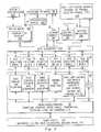
- FIG. 2is a simplified schematic of one example of client/server network architecture according to theft invention.
- FIG. 3is a more detailed schematic view of that which is shown in FIG. 1 .
- FIG. 4a schematic view of, inter alia, a data acquisition core according to the instant invention.
- FIG. 5is a flowchart view of an alarming process having severity levels according to the instant invention.
- FIG. 8is a screenshot view further illustrating the bargraph view according to the instant invention.
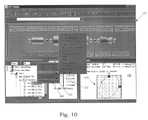
- FIG. 10is a screenshot view illustrating views of the unified graphical user interface including a plot view and a plot selection menu according to the instant invention.
- FIG. 11is a screenshot view illustrating views of the unified graphical user interface including a plot session graphical view and a plot session hierarchical view according to the instant invention.
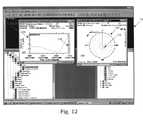
- FIG. 12is a screenshot view illustrating views of the unified graphical user interface including trend and polar plot views having synchronized cursors.
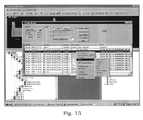
- FIG. 13a screenshot view illustrating views of the unified graphical user interface including an event manager view according to the instant invention.
- FIG. 14is a screenshot view illustrating different views of the unified graphical user interface including a hierarchical enterprise explorer view, an enterprise graphical view and a history plot view according to the instant invention.
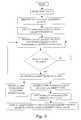
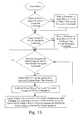
- FIG. 15a flowchart view of the object navigation process according to the instant invention.
- FIG. 16is a schematic view of, inter alia, a configuration module according to the instant invention.
- FIG. 17a screenshot view illustrating views of the unified graphical user interface including a configuration hierarchical enterprise explorer view, a configuration enterprise graphical view and a configuration instrument graphical view employed when configuring an enterprise.
- FIG. 18is a flowchart view of object architecture of the display and configuration modules shown in FIG. 6, and further detailing various plot objects according to the instant invention.
- FIG. 19is a flow diagram of the synchronize cursor method according to the instant invention.
- FIG. 20is a screenshot view illustrating views of the unified graphical user interface including a real time plot view, a real time plot configuration view and a plot session hierarchical view according to the instant invention.
- reference numeral 10is directed to the industrial plant asset management system according to the instant invention.
- the display module 100includes a software module that displays data in the database module 80 or in the data acquisition module 20 on, for example, one or more computers or display clients via the unified graphical user interface 102 . Communication with the data acquisition module 20 is what permits the real-time display of data such as orbits during a machinery start-up.
- the display module 100can be viewed as having two levels of display: basic navigation/operator display and full machinery management display.
- Configuration toolsare used to configure all data acquisition devices including instrumentation, construct machine train diagrams, and define the enterprise (i.e., the logical arrangement of machinery assets within the plant). Configuration tools and configuration information existing in the system 10 is preferably available for system extenders as well.
- Data exporter modules 300are interfaces that allow the system 10 to communicate with control and automation systems including third party control and automation systems. These exporter modules 300 can include the following interfaces: an object linking embedding (OLE) interface for process control, for example OLE for process control (OPC), a Dynamic Data Exchange (DDE) interface, and a Standard Query Language (SQL) interface. Custom Interfaces are interfaces to select third-party applications (i.e., Human Machine Interface (HMI), Historians, Computerized Maintenance Management System (CMMS), etc.)
- OLEobject linking embedding
- DDEDynamic Data Exchange
- SQLStandard Query Language
- Custom Interfacesare interfaces to select third-party applications (i.e., Human Machine Interface (HMI), Historians, Computerized Maintenance Management System (CMMS), etc.)
- an exporter modulecan interface between the data acquisition module 20 and a client user. Similar to the display client, each exporter can request real time data from the data acquisition module 20 or stored data form the database 82 .
- the exporterhas two main layers. One layer communicates with the modules of the system 10 to retrieve data. The other layer converts that information into the protocol requested by the user.
- Network Dynamic Data Exchange (NetDDE) and OPCare examples of protocols that the exporter preferably supports.
- the system extender (SE) modulesextend the functionality of the system 10 and can include data importers such as OLE for Process Control (OPC), Dynamic Data Exchange (DDE), Standard Query Language (SQL), and machinery information management open system alliance (MIMOSA). Additionally, the system extenders can include decision support modules, performance monitoring modules, balancing modules, alignment modules, oil analysis modules, rotor modeling modules, rolling element bearing database modules, and document management modules.
- OPCOLE for Process Control
- DDEDynamic Data Exchange
- SQLStandard Query Language
- MIMOSAmachinery information management open system alliance
- the system extenderscan include decision support modules, performance monitoring modules, balancing modules, alignment modules, oil analysis modules, rotor modeling modules, rolling element bearing database modules, and document management modules.
- FIG. 2a simplified schematic of one example of the client/server network architecture according to the instant invention is shown wherein the database module 80 resides on one or more servers S 1 , S 2 , . . . S N , the data acquisition module 20 resides on one or more data acquisition nodes or computers DAC 1 , DAC 2 , . . . DAC N , and the display modules 100 resides on one or more display clients or computers DC 1 , DC 2 , . . . DC N .
- the system 10can be based on a client/server network architecture employing at least one server, one or more computers, network controller cards, hub(s) and, for example, an Ethernet protocol communications link for configuring the system 10 as a centralized network, a distributed network, or any combination of the two as known to those having ordinary skill in the art, and informed by the instant disclosure. Additionally, the system 10 can be constructed as a wide area network (WAN) for managing a plurality of enterprises.
- WANwide area network
- the mouse deviceis one exemplary input device with wide user familiarity.
- the mouse device 104will be employed in the description infra as the input device for navigating a display pointer about the graphical user interface 102 .
- the mouse 104includes a “right” actuation device or button 106 and a “left” actuation device or button 108 .
- the left mouse button 108is generally used for, inter alia, selecting, dragging and opening an object when actuated or clicked on that object.
- the right mouse button 106is generally used for, inter alia, opening one or more menus and dialog boxes associated with an object when actuated or clicked on that object.
- clicking or actuating the right mouse buttonwill hereinafter be referred to as a right click and clicking or actuating the left mouse button will hereinafter be referred to as left click.
- the data acquisition module 20can be apportioned into a plurality of data collector modules 50 , a data acquisition core 22 and into one or more exporter modules 300 .
- the data collector modules 50preferably include modules for collecting data from fixed parallel devices including online continuous devices, from wired and wireless scanning/sequential devices including online scanning or multiplexing devices, from off-line diagnostic and surveillance devices including portable data collectors, from condition monitoring devices such as oil analysis, from processes devices, and from third party devices which can include machinery protection devices, machine and process controllers, applicable data sources, et cetera.
- a portable data collector module, a TDXnet® data collector module (communications processor) manufactured by Bently Nevada Corporation located in Minden, Nev., and an OPC data collector moduleare specific examples of data collector modules 50 for specific data acquisition devices 60 . These modules collect the data via each of the devices known supported protocol and convert it to a standard input that is received by the core data acquisition module 22 for further processing.
- different data collector modules 50simultaneously interface with continuous on-line monitoring devices, periodic on-line scanning or multiplexing monitoring devices, off-line diagnostic devices, portable surveillance/diagnostics devices, process devices and other conditioning monitoring devices for acquiring data from a multiplicity of measurement points throughout an enterprise.
- the data acquisition core module 22provides a data-conditioning layer between the physical world and both the database module 80 and the display module 100 .
- the data acquisition core 22includes means for real time interfacing with both the database module 80 and the display module 100 for providing real time export and real time display of data.
- the data acquisition core 22is configuration sensitive thereby providing proper scaling for the connected information flows. It also provides alarming functions for simple and parametric alarms.
- Data acquisition core module 22is comprised of a data collector module interface 24 , a data acquisition main module 26 (DAQ Main 26 ), a database interface/queue module 28 , a point repository module 30 , a request processor/session manager module 32 (real time interface), a hierarchy manager module 34 , an event processor module 36 , and a Boolean function manger module 38 .
- the data acquisition main module 26controls the starting and stopping of the other modules of the core 22 and may run as a service (the module is started when the system boots). Additionally, the data acquisition main module 26 is the module that is signaled by a configuration module (please see FIG. 9) of the system 10 when configuration changes are made to the system 10 . The data acquisition main module 26 passes this information to the other core modules so that they can adjust to the new configuration. For example, a point repository module 30 , to be discussed hereinbelow, is updated when the user changes alarm configurations. Furthermore, the data acquisition main module 26 handles the communication with a data acquisition connection manager 42 .
- the point repository module 30is a repository of point data (data collected from individual transducers including sensors) and status. This module receives data collected by the hardware on a point basis and initiates alarming on the collected data. The point repository module then adjust the status on the points if an alarm is detected or if a point is no longer in alarm and then reports this status change to the historical/machine database 86 and to any clients requesting it.
- the system 10includes both hardware-generated alarms and software-generated alarms. Hardware-generated alarms are specific to and evaluated by each individual hardware device. The results of these evaluations are returned to the system 10 for processing and display. Generally, hardware-generated alarms include over and under alarms that the user sets for a specific instrumentation such as monitoring system via the configuration utility module 202 and/or configuration object 150 to be explained infra. In one form, the hardware-generated alarms include two levels of alarms: alert and danger.
- Amplitude and phase regions that are in an “acceptable” regiondefine the acceptance region alarms. Thus, if a vector value goes outside of this region, it will be in alarm.
- the “acceptable” regioncan be defined by the user or configured to predetermined default values.
- Spectral band alarmsinclude full and single spectrum alarms.
- Parametric alarmsare alarms that are defined by using Boolean logic to combine a variety of conditions into one event which is preferably assigned a severity.
- the system 10allows the user to define or configure a plurality of severity levels to each alarm.
- the zero severity levelcan mean that a variable, event or parametric value is acceptable while increasing levels mean that the variable, event or parametric value has an increasing severity.
- hardware generated alarmswould normally have a higher severity level such as a severity level of three ( 3 ) or four ( 4 ), but this is totally configurable by the user.
- the usercan also configure a color for each severity level.
- the alarm eventis reported to any client viewing the data acquisition module who reported the alarm.
- the alarmsare not the only thing reported.
- the severity levelis also reported because that is what determines the color displayed on the unified graphical interface 102 .
- this unique alarming that the system 10 performsis very flexible and can be configured to meet the user's needs.
- the point repository 30preferable reports, via event processor 36 and database interface/queue module 28 , any alarms to the historical/machine database 84 including reporting the respective severity levels.
- the request processor/session manger module 32is the interface to the display clients DC 1 , DC 2 , . . . DC N for real time data display.
- This moduleallows display clients DC 1 , DC 2 , . . . DC N to request that a session be set up and the module 32 then updates the display clients on a given interval. These sessions can return static data, dynamic data or asset status.
- This moduleis also the interface for one-time data collection requests such as reference (baseline) data collection.
- the request processor/session manger module 32is the interface to the data exporter modules 300 .
- the data exporter modules 300can include an exporter module which includes two layers: a lower layer that requests data from the data acquisition core 22 or the database 82 , depending on the request for real time or stored data, and a upper layer that takes the data and transforms it into a protocol requested by the customer application (please see FIG. 3 ).
- the event processor module 36controls the writing of events to the event list 85 of the system 10 . Thus, if an alarm is detected (hardware or software) it is reported to this module and then put in the event list 85 . This module also controls any actions that a user may want to put into action as a result of a given event. For example, if a software alarm is detected, a user may want more data to be collected on a specific machine train. That action will be configured and event processor module 36 will signal that collection to be carried out. Note that events are not restricted to alarms. Events may be, inter alia, changes in the running of a machine and actions can be configured that will accomplish something when these events occur.
- the database interface/queue module 28is the interface to the relational database 82 including databases 84 and 86 .
- each of the data acquisition modules 20 that needs information from either database or needs to write information to either databaseuses this module to complete this operation.
- the database 82is preferably a high performance relational database that includes asset configuration, instrument configuration, compressed data, and non-compressed data.
- the database 82is able to store streaming real time data from online data acquisition devices. It also stores periodic data from external data sources and portable data collectors.
- a key to the design of the system 10is its ability to normalize these inputs into a predefined standard so it is easy for the database 82 to store data and for the display application to present data in a consistent manner regardless of its source.
- the main data source for the database 82is normalized transducer/sensor data acquired from the data acquisition core 22 .
- the database 82also outputs data to the data exporter modules 300 for use by external applications including external database 304 and customer applications 306 (please see FIG. 3 ).
- the database 82also outputs preprogrammed events to external applications and to a variety of media.
- the databasecan output data to event notification devices 308 such as email, pagers, telephones, cellular phones or other human machine interfaces.
- the display module 100uses a connection interface and scripting based logic to link a collection of independent objects and views together into object groups that function together to provide asset management and machinery diagnostic services.
- the two main linksare navigational and time.
- objectsare linked through time and/or location.
- a time linkspecifies a historical span in time, such as from one particular date to another particular date or as a current or real-time link.
- Locationrefers to a location within a plant including object assets (e.g., plant, unit, machines, couplings, bearings, seal, et cetera), instrument assets such as monitoring systems and transducers/sensors, and knowledge assets such as predetermined data presentations useful to view assets. Additionally, location refers to physical or abstract structures.
- the object architecture of the display module 100allows objects to choose to participate in links or act independently. If an object chooses to participate in a link, it can register this request through a main application class 110 , and subsequently receives link commands.
- an enterprise tree object 112presents, via the unified graphical user interface 102 , a hierarchical enterprise tree view 152 in a widow 154 of asset objects or asset representations.
- the enterprise tree object 112participates in a navigation link as the user navigates through the enterprise tree 152 , other objects participating in the navigation link update to the current location in the enterprise.
- the hierarchical enterprise tree view 152behaves similarly to the familiar “Windows® explorer view” showing a hierarchical explorer view 152 of the enterprise.
- the hierarchical enterprise tree or enterprise explorer view 152is analogous to the familiar file and folder view that allows users to navigate in a hierarchical manner.
- this viewallows navigation effortlessly from typical object assets such as plant, unit, machine, bearing, seal, to instrument assets such as monitoring systems, to transducers/sensors, and to knowledge assets such as predetermined data presentations (e.g., plots) useful to view assets.
- the enterprise tree object 112clearly represents each asset with a correlative descriptive icon on the unified graphical user interface 102 as exemplified in FIG. 7 .
- the enterprise tree object 112can also include filters that allow the user to view only certain asset objects and/or only certain assets and their associated attributes. Placing filter menus on the explorer window 154 can access these filters.
- the explorer window 154can include a first filter menu 156 that allows the user to view all plants (e.g. petrochemical plants, power generation plants, et cetera), all groups (e.g. crude unit A, crude unit B, Unit 1 , et cetera), all trains (e.g. turbine trains, pump trains, et cetera), or all measurement points on the assets.
- the explorer window 154can include a second filter menu 158 that allows the user to sort assets based on their attributes such as alarm status.
- the enterprise tree object 112can also visually show current alarm status on the hierarchical enterprise tree view 152 and propagate those statuses through the hierarchy, providing detailed alarm and summary alarm views simultaneously.
- the enterprise tree view 152reveals that an alarm is present by displaying the “Power Gen Plant” object in a configurable severity level color highlight as discussed supra. The user can then follow the color highlighting course by clicking on the severity level color highlighted objects which in this example include the “unit 1” object, the “300MW TG” object and the “BRG 2 Vert” object. Clicking on the “BRG 2 Vert” object reveals that the cause of the alarm is a direct reading on the vertical two bearing.
- the alarming and severity level color highlighting features of the instant inventionprovide the user with continuous visual feedback that rapidly guides the user to the alarming event by following a severity level color highlighted course or path.
- the enterprise view object 118 and thus, the enterprise view 160participate in the navigation link.
- the graphical enterprise or asset view 160follows the navigation although the user is not directly interfacing with the asset view window.
- These linked viewsmay be driven by the user or by alarms. Because all views are linked exploring root cause of alarm is rapid, one click and the user sees the asset where the alarm is and instrumentation that generated it. For example, and referring to FIG. 7, one click on the “300 MW TG” object in the explorer view 152 results in the user being presented with the asset view 160 shown in window 162 that visually presents a severity level color highlighted measurement location 165 that has the same configurable severity level alert color as that presented in the explorer tree 152 .
- the instant inventionspeedily presents the user with visual feedback in both windows 154 and 162 of the cause of the alert and these window views are linked to follow each other's navigation. Additionally, the user can drill down the objects in the graphical enterprise or asset view 160 by subsequently clicking on severity level color highlighted objects for following a severity level color highlighted course or path to an alarming event.
- a bargraph object 116presents graphical bargraph views 166 in a bargraph window 168 , via the unified graphical user interface 102 .
- Bargraph objects 116can participate in navigation links and can be customized and configured on a per user basis.
- userscan create customized bargraphs containing only particular points of interest and these customized bargraphs can be stored as files and shared between users.
- the bargraph views 166graphically show current values via dynamically changing graphical bars 171 .
- the bargraph views 166can also show one are more alarm level or setpoints.
- the alarm levels 173 , 175show setpoints configured for measurement location 177 .
- the bargraph views 166can show current values via nomenclature 179 and graphically show current status nomenclature (e.g. ok, not ok, alert, danger, alarm and no data).
- an indicator 181may be provided which may flash when the asset is in an alert, danger or alarm status.
- the indicators 181are preferably highlighted with the same configurable colors for alert, danger and alarm statuses as used for objects that are in these statuses in the explorer and asset views.
- bargraph objectscan participate in links.
- the usercan selectively display the bargraph.
- the bargraph view 166may simultaneously follow thereby allowing the user to have visual feedback in the form of bargraphs including the bargraph 169 of the vertical bearing two showing the graphical bar 171 in the same configurable severity level color highlight as the associated alarming objects are shown in both the tree view 152 and the graphical view 160 .
- bargraph 169shows the graphical bar acceding the setpoint 173 and displays nomenclature 179 that numerically details the bargraph value and shows that this asset is in an “alert” condition.
- indicator 181can flash the highlighted alert color.
- FIG. 8exemplifies further graphical bargraphs that can be displayed in the bargraph window 168 via the bargraph object 116 .
- FIG. 8shows, a 1 ⁇ amplitude bargraph and a corresponding 1 ⁇ phase bargraph thereby defining a vector value.
- Amplitude and a phase bargraphscan also display regions for defining an acceptance region such that an alarm event will occur if the associated vector value falls outside of the defined acceptance region.
- an instrument tree object 118presents, via the unified graphical user interface 102 , a hierarchical instrument tree view 170 in an instrument tree view window 172 .
- the hierarchical instrument tree view 170behaves similar to the hierarchical enterprise tree view 152 and thus, it behaves similar to the familiar “Windows® explorer view” for showing enterprise installed instrumentation including data acquisition devices 60 .
- the unified graphical user interface 102preferably represents each instrument object with a correlative descriptive icon.
- the Instrument view 174allows the user to see status, alarms, and configuration referenced from the instrumentation system including data acquisition devices 60 . Instrument assets may be controlled (for instance resetting machine protection alarms) and configurations may be changed in this view.
- the instrument view 174can participate in links and is always synchronized with the other views of the system 10 .
- the plot objectcan present, via the graphical user interface 102 , asset data plots on multiple points simultaneously. It is unique in its ability to present real time data and historical data simultaneously.
- Real time datacomes directly from transducers/sensors 70 via the data acquisition core 22 and provides results similar to connecting an oscilloscope, chart recorder, meter or spectrum analyzer directly to a measurement point.
- Historical datais retrieved directly from the relational database 82 and might be from non-real time devices such as a portable data collector or it might be stored real time data.
- the systemhas a wide variety of plot choices which include, but are not limited to, orbit (x vs.
- a plot groups object 126provides a collection of similar plots (such as Orbit or Trend plots). Plot groups allow the user to page through large sets of plots included in the system 10 and view these sets in the plot view window 180 via the unified graphical user interface 102 .
- Plot sessionscan participate in links. Sessions can be saved, and retrieved. Plot Sessions can be saved locally (on the display client) for private viewing, or shared in the database 82 , for example the configuration database 86 , for multiple users viewing and editing.
- Plots sessionscontain a single configuration that can be applied to all plots in the session (such as time range). Plots in the session can operate independently, or use the single session configuration.
- a plot sessioncan be configured to show orbit plots in the plot view window of data collected from a pair of displacement points (displacement point A and displacement point B) at defined time intervals (5:30, 6:00, 6:30, 7:00, 7:30 and 8:00). Furthermore, the plot session object 128 allows the user to page through large sets of plot groups included in the system 10 and view these groups in the plot view window 180 via the unified graphical user interface 102 .
- the plot session object 128uniquely provides a synchronized cursor link through plot groups object of multiple plot windows brought up or opened simultaneously via a menu 250 .
- a polar plot 252 having a first cursor 254 and a trend plot 256 having a second cursor 258are shown in plot windows 180 .
- the plot groups objectlinks these two cursors together via the synchronized cursor link 127 .
- the second cursor 258 in the trend plot 256automatically “scrolls” to the same sample as the driving plot or as scrolled to with the first cursor.
- the first cursor 254 in the polar plot 252automatically “scrolls” to the same sample as the driving plot or as scrolled to with the second cursor 258 . This allows the user to quickly and simply compare and correlate data from different and same plots.
- a plot session tree object 130(similar to the enterprise and instrument tree objects) shows a graphical plot session tree view 260 , via the graphical user interface 102 , of all available plot sessions.
- the plot session tree 260is unique in its ability to show all configured plot groups as the plot session is being constructed. The user can then quickly see what plots have been added to the plot sessions and choose to open, close and edit individual plot groups, and entire sessions from the plot session tree view 260 .
- the instant inventionincludes a variety of plot objects and views that will now be further explored from a user standpoint.
- the usercan simply select a point or variable, and choose the plot of interest, and a default plot will be presented.
- the system 10allows plotting for the high-end diagnostics engineer who demands maximum flexibility and customization.
- Simple Plottingis where a user selects a point or variable anywhere in the system and chooses a plot. Most commonly, the user will select a point or variable in the enterprise tree and choose a plot. If the user chooses a point then a default set of variables will be used to produce a plot, and if the user chooses a variable, the user can be specific about exactly what variable the user would like to see. For example, if the user selects a point on the tree, and chooses the trend plot—the user will be presented with a single trend plot showing the 1x and direct variables. On the other hand, if the user wants to see a trend plot for just, say, GAP, then the user can select the GAP variable, and then select a trend plot.
- the basic model of plottingis as follows.
- the main unit of plottingis what is referred to as the plot group.
- the plot groupincludes of one or more plots.
- Each plotin turn, is composed of one or more variables.
- At the top of the modelis something like the plot session, which is composed of plot groups.
- a simple illustrative hierarchyis as follows: plot sessions contain plot groups, plot groups contain plots, and plots contain curves.
- a single plotcan show one or more variables.
- the usercan view a plurality of variables at the same time for performance comparative analysis across multiple variables on a single plot.
- all plots in the system 10plot multiple variables on a single plot.
- the system 10can overlay either different variables, or the same variable, but at different times in the same plot.
- the usercould create a polar plot and show the 1 ⁇ and 2 ⁇ variables in the same plot or, the user could produce a polar plot that shows two sets of 1 ⁇ data, one set being from, say, last month, and the other set being from last year.
- a plot groupis just a collection of plots that appear in the same window.
- the usercan create a plot group that consists of ten trend plots. Each of those trend plots can contain ten variables. If the user chooses to show two plots per page, then the user would have a total of five pages of trend plots to flip or page through. In each plot group, the user can create an arbitrary large number of plots, and choose how many plots per page the user wishes to view.
- Plot configurations of the system 10include a number of choices and options. It is not necessary that the user knows or configures each of these options. Each time the user brings up a plot configuration screen, non-configured options are preferably filled in with simple defaults the user can either override or leave alone.
- the system 10saves the plot group's configuration including the configuration for everything in a plot group (plots, data sets in plots) for later viewing. The system 10 also allows the user to save multiple plotting configurations into a single plot session for later viewing.
- an event manager object 132is a special plot presentation that displays an event manager view 262 of both system and alarm events.
- System eventsare specific events in time that refer to the health and operation of the system 10 .
- Alarm eventsare exception conditions that occurred on assets coupled to the system 10 .
- the event manager object 132supports both navigational and time links. Additionally, the event manager object allows the user to filter alarms via a filtered selection display 264 thereby allowing the system 10 to provide filtered status on any location in the Enterprise as the user navigates through the system 10 .
- the Event Manager 132further allows the user to launch plots via menu 266 from the event manager view 262 to present supporting evidence for any given event.
- the history plot objectcan include event markings 186 .
- the event markings 186can be used to link to the event manager 132 and thus the event manager view 262 (FIG. 13) such that a listing of all events associated with the system 10 for the specified time frame can be quickly accessed.
- Eventsinclude alarms, diagnostic statuses, asset events (such as start up shutdown), and configuration events.
- the viewsare linked. Clicking on an event associated with an asset will cause other active displays to display information associated with the event. This information might be the trend plot for the variable that caused the event (time view), the physical location of the asset (enterprise view), all associated plots and hierarchical navigation options (explorer view), and a time base plot of the variable (plot view).
- the history plot objectcan include one or more journal markings 188 that provide a link that to a journal editor object 140 such that a listing of journal entries can be viewed and edited for any enterprise or instrument location.
- a status manager object 136presents, via the graphical user interface 102 , all current status information for any location in the enterprise via a status manager view in a status view window.
- the status manager objectdisplays all current status information for any location in the enterprise.
- the status manager viewis navigable, as the user moves through the enterprise; the status manager will link to the current enterprise location and provide real time statuses.
- An archive manager/database utilities object 144provides an archive manager that allows the user to back up or archive their database.
- the archive managercan archive the entire enterprise data, or a portion of the enterprise, all the data, or a piece of the database 82 in time.
- Archived datacan be stored on any media, fixed or removable. Archives can be viewed while the system is off line and can be shared with other system 10 users.
- the archive managercan participate in links.
- a portable control module 146controls uploads and downloads of routes to and from a portable data collector. The user can configure and manage the portable data collector through the portable control module 146 .
- An asset management or properties object 148provides, via the graphical user interface 102 , an asset management or properties view of each asset. This allows users to view asset information and such as: serial numbers, installation dates, manufacturer and model number, machine specifications, process information, linking to manuals and engineering drawings, maintenance history and photographs. These views preferably appear as dialogue boxes that can be accessed by selecting properties 149 on the menu shown in FIG. 10 .
- a configuration object 150presents, via the graphical user interface 102 , screens that show and allow the user to edit the configuration properties of any enterprise or instrument object. This view is linked to the instrument, enterprise and explorer views. Thus, from any object in the enterprise or instrument hierarchies or other view in the system 10 , the user can view and edit the configuration properties for that location or instrument without leaving the currently selected navigated location (the point being worked on). These views preferably appear as dialogue boxes that can be accessed by selecting configuration 151 on the menu as shown in, for example, FIG. 10 .
- any objectcan either accept navigation commands or give navigation commands.
- the enterprise tree object 112 and the enterprise view object 114both accept and give navigation commands.
- the view object 114wants to be notified, and when the user navigates in the enterprise graphical view 160 , the tree object 112 wants to know. So, in this example, both the enterprise tree object 112 and enterprise view object 114 accept and give navigation commands and may or may not be directly linked.
- main 110is the “command” central where all links are routed through. It should be noted that this design does not preclude objects from establishing direct links to each other, but the command center (main 110 ) does provide benefits that will be explored in further detail infra.
- main 110the benefit of routing all commands through main 110 is a substantial decrease in the number of required links. Specifically, if objects were directly linked there would be a resultant of N*N links whereas by employing the central command object main 110 according to the instant invention there is a resultant of only N links. Thus, the direct linking method would require four hundred links for twenty objects while employing main 110 according to the instant invention requires only twenty links.
- each object that implements INavigateSourcecan take “multiple” references to objects that it will send navigation commands to.
- the enterprise view object 114can accept references to multiple objects wanting to accept navigation commands from the view object 114 .
- the enterprise view object 114supports both the INavigate and INavigateSource interfaces.
- main 110creates the view object 114 , it queries first for the INavigate interface, and puts this interface into its map of navigating objects.
- Main 110queries for the INavigateSource interface and then gives the enterprise view object 114 a reference to its own INavigate Interface.
- the enterprise view object 114has a reference to mains 110 INavigate interface.
- the view object 114calls back on mains' INavigate interface to notify main 110 that the user has navigated.
- the same navigational model used aboveis also used for scripting all other commands together. For example, when a user right clicks on the event manager object 132 , the user sees a rich list of commands that come from main 110 . When a user right clicks on an object, they first put their own specific commands in the menu, then ask main 110 to fill up the rest for them.
- segment identifierThis is a central component to the system 10 and is the identifier for any object in the system.
- segment identifiersidentify all Enterprises, Plants, Machine Trains, Machines, Point and Variables.
- the segment identifiersdictate the commands or actions a user can perform on an object.
- IPopUpMenuthere are two interfaces created which can be defined as IPopUpMenu and IPopUpMenuSource.
- the bargraph objectwishes to participate in command links—so it implements the IPopUpMenuSource interface.
- main 110creates the bargraph (or any object) it asks the bargraph if it supports the IPopUpMenuSource interface. It is does, main 110 gives the bargraph a reference to its (main 110 ) IPopUpMenu interface.
- the bargraphWhen the user selects one of those commands, the bargraph simply forwards that command to main 110 through the IPopUpMenu interface it has for main 110 . Main 110 will then carry out the command.
- the enterprise view object 114has no knowledge that the user is bringing up configuration screens. It simply got a list of commands or actions that can be performed on that segment ID. If the user chooses one of those commands, it forwards that request to main 110 .
- the usercan choose what method of synchronization—synchronize on sample Number, synchronize on speed, synchronize on time, or synchronize on frequency.
- the architectureis designed such that plot groups can “elect” or volunteer to participate in the synchronization of cursors in a given plot session analogous to the above navigational link discussion.
- the plot group 126is the separate window that houses or contains plots.
- the plot groupis the main “visible” component that the user interacts with. The user can manipulate the plot group to preferable show 1 plot per page, or 2 or 4 or up to 8 plots per page. The user can scroll through plots in the plot group, print the plot group, etc . . . .
- Each plotcontains multiple (one or more) curves. If the user moves a cursor in a given plot—the plot first will synchronize the cursors contained in a single plot. Next, the plot forwards a message to the plot group that the user has moved the cursor. The plot group then sends a message to all it's plots to synchronize cursors, then forwards a message to its plot session. The plot session then turns around and repeats the message to all plot groups. Plots groups that have elected to join inter plot group synchronization will then send a message to all their plots to synchronize cursors, and each of those plots will synchronize cursors for all curves.
- the configuration module 202 of the system 10is a software module that allows users to configure the actual plant layout and the associated physical assets including the physical appearance of each asset or machine. Similar to the display module 100 , the configuration module 200 presents, via the unified graphical user interface 102 , a configuration explorer view 310 in an explorer view window 312 , a configuration graphical view 314 in a graphical window 316 and a configuration instrument view 318 in a instrument view window 320 . As noted supra, when the user navigates through the system each view is linked. For instance, if the user clicks through the configuration explorer view 310 , the configuration graphical view 314 in the graphical window 316 follows the navigation although the user is not directly interfacing with window 316 .
- the usercreates a new enterprise by interacting with the unified graphical user interface 102 .
- the usercan create an enterprise node named Plant A by using the file menu located on the top toolbar.
- the configuration module 202communicates with one or more servers S N and builds a database for this enterprise node in one or more configuration databases 86 .
- the enterprise configurationcan cooperate with one or more data acquisition computers DAC N and thus, with a plurality of data acquisition devices 60 and describes the data collection process and the instrumentation connected to the data acquisition computers DAC N .
- the userstarts populating this enterprise with machine assets by selecting the enterprise node and using menus and dialog boxes.
- the usermay populate the enterprise with, inter alia, turbines, pumps, couplings et cetera.
- the usercan associate each asset or node in the enterprise with a name and with a tag.
- each machine assetcan be populated with instrumentation assets by using menus, which associate further assets to the selected machine asset, and by using dialog boxes which allow the user to associate properties with the particular asset selected from the menu.
- menus and dialog boxescan be used to populate the instrumentation assets with transducer/sensor assets which may be associated with one another.
- a timing transducer or phase reference transducermay be associated with a proximity transducer for obtaining 1 ⁇ waveforms by selecting each asset and using an association selection on a menu or dialog box provided by the configuration module 202 .
- Measurement points or transducer/sensors 70can also be associated with one another to present, for example, specific plot presentations like an orbit plot.
- process information from transducer/sensors 70can be associated with, for example, vibration information from transducer/sensors 70 for presenting both process information and machine monitoring information.
- the configuration module 202maintains the historical configuration of an asset and previous versions of the configuration can be restored. In addition, module 202 can maintain the ability for the user to view data for points whose properties have changed, or that have been deleted.
- a template manager 206allows a user to add pre-configured components to an enterprise being configured. It also allows the user to create custom pre-configured components to be used by the system 10 . For example, a user may have five identical trains in a plant. Each of these trains has identical properties. The user can save the configuration for one of these trains as a template. This template can then be added to the system numerous times in order to configure the additional trains.
- a preference module 208is interfaced between the common tree manager 204 and the configuration database 86 for providing the user with configuration of various preferences for the interface 102 .
- the configuration module 202further includes an object store module 210 that provides interface pointers to the configuration objects, creates configuration objects and destroys configuration objects. This is the common interface for trees to communicate with one another. Additionally, object store module 210 builds the icon list that the trees and template toolbars use.
- a data collection groups module 212is interfaced between the configuration object 150 , the configuration database 86 and the object store module 210 for providing the configuration of data collection groups. This allows the user to group a set of points together for the purpose of taking specific actions on all members of that group. For example, measurement locations can be grouped into a set of collection groups and if one location in the collection group goes into alarm, data collection can occur for all points in that group. Collection groups can also be enabled based on events other than alarms. Locations in one group are not restricted to belonging to one train. They can span multiple trains.
- a parametric events module 214provides dialogs for displaying and creating parametric events. Parametric events allow the user to group different individual events including alarms using Boolean logic. When the conditions of the Boolean equation are met, module 214 can be used to drive a specific action. This allows the user to configure an action based on one or more events occurring. For example, if a speed exceeds 3600 rpm and the time is 9:00 a.m., then enable a set point.
- Setpoints module 216provides dialogs for displaying and editing, inter alia, acceptance regions 217 , spectral bands 219 and bargraph setpoints 221 .
- the graphical user interface 102in combination with the configuration module 202 allows the user to view data when setting set points.
- Action manager module 218provides dialogs for creating and displaying configured actions. Additionally, an event manager module 220 interfaces to the database 82 for obtaining and displaying setpoints, spectral bands, acceptance regions, actions, and parametric events. Furthermore, a security manager module 222 provides configuration security settings for the system 10 . Security is configured based on the logged-in user and certain tasks, such as editing set points or acknowledging events. Security settings can also be based on the particular instrumentation. For example, a user can be given access to edit the configuration for a portable system, but not for an on-line system. Moreover, a print manager module 224 provides for configuring printer settings, and printing of all configuration reports.
- Component Management Groups module 226is interfaced between the configuration object 150 , the configuration database 86 and the object store module 210 for allowing the user to easily change properties for a set of similar assets.
- the usermay have ten identical machines. Some of the properties for these machines may have been incorrectly configured. If the machines are part of a component management group, the user can correct the configuration in one place thereby resulting in all components of that group being automatically updated.
- a document manager module 228provides the configuration interface to the document view 229 presented by the document object 138 .
- View wrapper module 230provides a window that contains the virtual view, and the database interface to the virtual view for the configuration module 202 .
- the virtual view control module 232cooperates with the view wrapper module 230 to provide virtual view control.
- Configuration dialog wrapper module 234provides the interface for displaying and editing of configuration data for the display module 100 .
- the configuration module 202can include predefined asset models.
- bearing module 236can be included which provides for the configuration of bearing components and can include a predefined database. In addition to direct user input, the bearing module 236 can also retrieve information from a third-party bearing database package.
- Predefined data module 238provides an interface to the database for commonly used data.
- the predefined data module 238is operatively coupled to an observation codes module 240 that provides for the configuration of user-defined observation codes.
- An observation codecan be used as a source of data for configured components. It is a text description of a condition that a user may observe while collecting data.
- a load and save module 242interfaces between the configuration database 86 and both the object store 210 and the data acquisition module 20 for handling the locking, opening and closing of the configuration database 86 .
- the load and save module 222can also include a change log that lists the changes made during the configuration session, as well as the logged-in user who made them. Additionally, the load and save module 242 handles final save and cleanup of the configuration database 86 .
- a time synching module 244creates a time synchronization event for synchronization of the data acquisition modules 20 .
- an external plug Ins module 246can be included for containing all the functionality for configuration of hardware-specific nodes. Each hardware device can be supported by a separate plug-in. This allows for configuration support of additional hardware devices, with minimal impact on the core configuration module 202 .
- the industrial plant asset management system 10includes a synchronized multiple view graphical user interface with real time and database interfaces, different configurations for different users and different types of users, a relational database with input and output interfaces and preferably, a knowledge manager as exemplified by U.S. Pat. No.
- 5,905,989which is hereby incorporated by reference in its entirety, a normalizing data acquisition element with real time and data base interfaces, a variety of device dependant Data collector modules with associated signal conditioning and processing means for connecting to a variety of asset management instruments (e.g., a 3500 Monitoring System manufactured by Bently Nevada Corporation located in Minden, Nev.) that are then connected to a variety of asset management transducers including vibration, temperature, pressure, flow, optical, torque, position, and others.
- asset management instrumentse.g., a 3500 Monitoring System manufactured by Bently Nevada Corporation located in Minden, Nev.
- the system 10further connects third party instrumentation systems, monitoring systems, machine controllers, process controllers, and field devices.
- the display module 100includes the unified graphical user interface 102 that allows users to view assets objects or asset representations through a variety of different window views and while the user navigates through the system 10 each view is linked. For instance and as detailed supra, if the user clicks through the enterprise explorer tree view 152 , the enterprise graphical view 160 follows the navigation although the user is not directly interfacing with the graphical view 160 or the graphical window 162 . This linked view may be driven by the user or by alarms. Because all views are linked exploring root cause of alarm is rapid—simply clicking the selection device results in the user seeing the asset where the alarm is and the instrumentation that generated it. Additionally, the display module 100 of the system 10 is sensitive to the user, as it allows the presentation of different views to machine maintenance specialists, machine operators, or instrument technicians.
- the diagnostic viewsimultaneously displays, via the graphical user interface 102 , the enterprise explorer window view 154 showing the hierarchical enterprise tree view of enterprises including a hierarchical view of asset objects or asset representations, the enterprise graphical window view 162 showing virtual views of two and three-dimensional asset objects or asset representations, and the plot session tree view 260 or in the alternative, the current value(s)/history window view 168 showing real-time asset objects or asset representations in the form of bargraphs or trend plots.
- the operator viewmay simultaneously display the enterprise explorer window view 154 and the current value(s)/history window view 168 on the graphical user interface 102 .
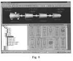
- the instrument viewsimultaneously displays the instrument explorer window view 172 including a hierarchical view of instrument asset objects or asset representation and the instrument graphical window view 176 including virtual views of two and three-dimensional instrument asset objects or asset representations (please see FIG. 9 ).
- all of these windowscan be repositioned and docked anywhere on the interface 102 .
- the diagnostic viewcan display an object model of the unit(s) (process train or machine train) in the enterprise graphical window view 162 that is correlative to the highlighted enterprise(s) in the plant explorer view 154 .
- an enterprise assetcan be that of a power generation plant having a machine train named unit one.
- the enterprise graphical window view 162 or virtual window viewwould then include a display of unit one when the associated power generation plant is highlighted in the enterprise or plant explorer window view 154 .
- the plot session tree view 260can include plot sessions or in the alternative, the current value(s)/history view 168 can include data on the highlighted enterprise.
- selecting the explorer power generation plant object by performing, for example, a single left click of the mouse 114reveals a machine train named unit one in the enterprise graphical window view 162 .
- Actuating the pointer on the explorer power generation plant object by, for example, performing a double left click of the mouse 114results in that object being opened or expanded to reveal object units of the actuated object and a plus sign that is disposed next to the object converts to a minus sign.
- the pointercan then be positioned on unit one and the user can actuate the pointer on unit one by, for example, performing a double left click of the mouse 114 , to reveal an asset object or an asset object group associated with unit one (e.g., the 300 MW TG asset).
- actuating a particular asset object groupshows the individual asset objects of that group and actuating any individual asset, for example, the 300 MW TG asset drills down or expands the asset into one or more instrument asset objects which in turn can be actuated to expand the instrument asset into one or more monitoring transducers/sensors asset objects. Actuating the pointer on transducers/sensors objects reveals the type of data that may be engendered therefrom.
- any asset objecte.g., an explorer plant object or unit object
- any asset objecte.g., an explorer plant object or unit object
- double left clicking the object or single left clicking the plus signwhen associated with a selected object, results in a synchronous display in the enterprise graphical window view 162 of one or more virtual asset objects correlative to the selected asset object such as the explorer plant object or unit object.
- the current value(s)/history view 168synchronously follows the other two windows for revealing real-time bargraph views and trend plots for assets.
- visual feedback of alarms including severity levels displayed in one windowsynchronously follows the other windows.
- visual feedback of a particular severity level highlighting of the plant object, unit object, or any other asset object in the enterprise graphical window view 162synchronously follows the particular severity level highlighting of the plant object, unit object, or any other asset object in the hierarchical enterprise explorer tree 152 .
- the usercan follow the severity level highlighting (e.g., a user configurable color as delineated supra) as the user opens assets objects or drills down the enterprise via either view for pinpointing the cause of the alarm.
- Actuating the pointer on any one particular asset object in the enterprise graphical window view 162 by, for example, performing a double left clickcauses that object to be expanded to one or more assets which are displayed in the enterprise graphical window view 162 as two or three-dimensional objects.
- the objects in the explorer viewwhich are associated with the objects selected in the graphical window view 162 , are automatically expanded.
- the enterprise graphical window view 162can be used to drill down from a unit asset object to asset object groups and then down to a particular asset object including associated monitoring transducer/sensor objects.
- the explorer window view 154synchronously.
- the usercan follow a course of alarm severity level color highlighting by drilling down the enterprise and following the color highlighting via the graphical window view for pinpointing the cause of the alarm.
- the instrument explorer window view 172 and the instrument graphical window view 176are also linked and work analogous to the enterprise explorer window view 154 and the enterprise graphical window view 162 , respectively.
- selecting an instrument asset object or asset representation in the instrument explorer window view 172results in that instrument being depicted via two or three-dimensional objects in the instrument graphical window view 176 .
- actuating an instrument in the instrument explorer window view 172 by, for example, performing a double left clickcauses that instrument object to be expanded into one or more instrument asset objects which in turn can be expanded into transducer/sensor asset objects associated with each instrument.
- the instrument explorer window view 172 and the instrument graphical window view 176also include visual feedback of alarms including severity levels for each window, which synchronously follow the other window.
- severity level highlightinge.g., a user configurable color as delineated supra
Landscapes
- Engineering & Computer Science (AREA)
- Physics & Mathematics (AREA)
- General Physics & Mathematics (AREA)
- Theoretical Computer Science (AREA)
- General Engineering & Computer Science (AREA)
- Business, Economics & Management (AREA)
- Human Computer Interaction (AREA)
- Automation & Control Theory (AREA)
- Economics (AREA)
- Software Systems (AREA)
- Development Economics (AREA)
- Operations Research (AREA)
- Accounting & Taxation (AREA)
- Manufacturing & Machinery (AREA)
- Entrepreneurship & Innovation (AREA)
- Human Resources & Organizations (AREA)
- Marketing (AREA)
- Finance (AREA)
- Quality & Reliability (AREA)
- Strategic Management (AREA)
- Tourism & Hospitality (AREA)
- General Business, Economics & Management (AREA)
- Testing And Monitoring For Control Systems (AREA)
- User Interface Of Digital Computer (AREA)
Abstract
Description
Claims (26)
Priority Applications (8)
| Application Number | Priority Date | Filing Date | Title |
|---|---|---|---|
| US09/515,529US6421571B1 (en) | 2000-02-29 | 2000-02-29 | Industrial plant asset management system: apparatus and method |
| CN01805670ACN1406348A (en) | 2000-02-29 | 2001-02-26 | An industrial plant asset management system |
| AU2001272091AAU2001272091A1 (en) | 2000-02-29 | 2001-02-26 | An industrial plant asset management system |
| EP01955107AEP1279074A4 (en) | 2000-02-29 | 2001-02-26 | An industrial plant asset management system |
| JP2001563957AJP5052725B2 (en) | 2000-02-29 | 2001-02-26 | Industrial plant equipment management system |
| PCT/US2001/006190WO2001065322A1 (en) | 2000-02-29 | 2001-02-26 | An industrial plant asset management system |
| US10/191,601US6775576B2 (en) | 2000-02-29 | 2002-07-08 | Industrial plant asset management system: apparatus and method |
| US10/196,007US6889096B2 (en) | 2000-02-29 | 2002-07-15 | Industrial plant asset management system: apparatus and method |
Applications Claiming Priority (1)
| Application Number | Priority Date | Filing Date | Title |
|---|---|---|---|
| US09/515,529US6421571B1 (en) | 2000-02-29 | 2000-02-29 | Industrial plant asset management system: apparatus and method |
Related Child Applications (2)
| Application Number | Title | Priority Date | Filing Date |
|---|---|---|---|
| US10/191,601ContinuationUS6775576B2 (en) | 2000-02-29 | 2002-07-08 | Industrial plant asset management system: apparatus and method |
| US10/196,007Continuation-In-PartUS6889096B2 (en) | 2000-02-29 | 2002-07-15 | Industrial plant asset management system: apparatus and method |
Publications (1)
| Publication Number | Publication Date |
|---|---|
| US6421571B1true US6421571B1 (en) | 2002-07-16 |
Family
ID=24051726
Family Applications (3)
| Application Number | Title | Priority Date | Filing Date |
|---|---|---|---|
| US09/515,529Expired - LifetimeUS6421571B1 (en) | 2000-02-29 | 2000-02-29 | Industrial plant asset management system: apparatus and method |
| US10/191,601Expired - LifetimeUS6775576B2 (en) | 2000-02-29 | 2002-07-08 | Industrial plant asset management system: apparatus and method |
| US10/196,007Expired - LifetimeUS6889096B2 (en) | 2000-02-29 | 2002-07-15 | Industrial plant asset management system: apparatus and method |
Family Applications After (2)
| Application Number | Title | Priority Date | Filing Date |
|---|---|---|---|
| US10/191,601Expired - LifetimeUS6775576B2 (en) | 2000-02-29 | 2002-07-08 | Industrial plant asset management system: apparatus and method |
| US10/196,007Expired - LifetimeUS6889096B2 (en) | 2000-02-29 | 2002-07-15 | Industrial plant asset management system: apparatus and method |
Country Status (6)
| Country | Link |
|---|---|
| US (3) | US6421571B1 (en) |
| EP (1) | EP1279074A4 (en) |
| JP (1) | JP5052725B2 (en) |
| CN (1) | CN1406348A (en) |
| AU (1) | AU2001272091A1 (en) |
| WO (1) | WO2001065322A1 (en) |
Cited By (255)
| Publication number | Priority date | Publication date | Assignee | Title |
|---|---|---|---|---|
| US20020002409A1 (en)* | 2000-05-31 | 2002-01-03 | Mitsubishi Denki Kabushiki Kaisha | Product control method using wireless communication |
| US20020123856A1 (en)* | 2001-03-01 | 2002-09-05 | Evren Eryurek | Cavitation detection in a process plant |
| US20020126137A1 (en)* | 2001-03-06 | 2002-09-12 | Kaestner Frederick G. | Data display device |
| US20020143557A1 (en)* | 2001-03-14 | 2002-10-03 | Gregory Vassmer | Computer program product for assisting a user to select among information units of a plurality of structured information units concerning bearings and seals |
| US20020147506A1 (en)* | 2001-03-01 | 2002-10-10 | Evren Eryurek | Fiducial technique for estimating and using degradation levels in a process plant |
| WO2002082302A1 (en)* | 2001-03-20 | 2002-10-17 | Daniel Management And Controls, Inc. | Method and apparatus for internet-based remote terminal units and flow computers |
| US20020161866A1 (en)* | 2001-03-20 | 2002-10-31 | Garnet Tozer | Method and apparatus for internet-based remote terminal units and flow computers |
| US20030041135A1 (en)* | 2001-08-21 | 2003-02-27 | Keyes Marion A. | Shared-use data processing for process control systems |
| US20030105751A1 (en)* | 2001-11-22 | 2003-06-05 | Van Domburg R.E. | Client-oriented information system |
| US20030135349A1 (en)* | 2000-07-04 | 2003-07-17 | Osamu Yoshie | System for diagnosing facility apparatus, managing apparatus and diagnostic apparatus |
| US20030139820A1 (en)* | 2002-01-18 | 2003-07-24 | Hideki Nagatsuka | Plant operating apparatus and method |
| US20030154051A1 (en)* | 2002-02-13 | 2003-08-14 | Kabushiki Kaisha Toshiba | Method and system for diagnosis of plant |
| US20040003007A1 (en)* | 2002-06-28 | 2004-01-01 | Prall John M. | Windows management instrument synchronized repository provider |
| US20040021687A1 (en)* | 2000-10-14 | 2004-02-05 | Aloys Wobben | Method for displaying the operating conditions of an installation |
| US20040024662A1 (en)* | 2002-08-02 | 2004-02-05 | David Gray | Equipment documentation management system, method, and software tools |
| US20040039970A1 (en)* | 2002-08-22 | 2004-02-26 | Barnard David L. | Method and apparatus to coordinate groups of heterogeneous measurements |
| US6710776B2 (en)* | 1999-12-28 | 2004-03-23 | Tlv Company Limited | Position finder, measuring apparatus with position finder, and measuring system |
| US20040075699A1 (en)* | 2002-10-04 | 2004-04-22 | Creo Inc. | Method and apparatus for highlighting graphical objects |
| US20040088119A1 (en)* | 2001-01-30 | 2004-05-06 | Guenther Landgraf | System for controlling and monitoring machines and/or systems with active components belonging to different active groups |
| US20040107114A1 (en)* | 2002-11-15 | 2004-06-03 | Curtis Peter M. | System and method for processing, organizing and accessing mission critical facilities information and intellectual capital |
| US20040107345A1 (en)* | 2002-10-21 | 2004-06-03 | Brandt David D. | System and methodology providing automation security protocols and intrusion detection in an industrial controller environment |
| US20040104946A1 (en)* | 2002-09-23 | 2004-06-03 | Yufeng Li | System and method for automated positioning of graphic objects |
| US20040104945A1 (en)* | 2002-12-03 | 2004-06-03 | Mentor Graphics Corporation | Graphical calculator with hierarchical view of usage history |
| US20040111499A1 (en)* | 2002-12-10 | 2004-06-10 | Dobrowski Patrick M. | Method for launching applications |
| US20040117624A1 (en)* | 2002-10-21 | 2004-06-17 | Brandt David D. | System and methodology providing automation security analysis, validation, and learning in an industrial controller environment |
| US20040133853A1 (en)* | 2002-09-23 | 2004-07-08 | Colleen Poerner | System and method for navigating an HMI |
| US20040139085A1 (en)* | 2002-12-30 | 2004-07-15 | Evren Eryurek | Data visualization within an integrated asset data system for a process plant |
| US20040139079A1 (en)* | 2002-12-30 | 2004-07-15 | Evren Eryurek | Integrated navigational tree importation and generation in a process plant |
| US20040153171A1 (en)* | 2002-10-21 | 2004-08-05 | Brandt David D. | System and methodology providing automation security architecture in an industrial controller environment |
| US20040158474A1 (en)* | 2003-02-06 | 2004-08-12 | Karschnia Robert J. | Service facility for providing remote diagnostic and maintenance services to a process plant |
| US20040162887A1 (en)* | 2003-02-19 | 2004-08-19 | Steven Dillon | Open network-based data acquisition, aggregation and optimization for use with process control systems |
| US20040181364A1 (en)* | 2003-03-13 | 2004-09-16 | Csi Technology, Inc. | Generation of data indicative of machine operational condition |
| WO2004067101A3 (en)* | 2003-01-26 | 2004-09-16 | Precor Inc | Service tracking and alerting system for fitness equipment |
| US6795798B2 (en) | 2001-03-01 | 2004-09-21 | Fisher-Rosemount Systems, Inc. | Remote analysis of process control plant data |
| US20040186927A1 (en)* | 2003-03-18 | 2004-09-23 | Evren Eryurek | Asset optimization reporting in a process plant |
| US20040201602A1 (en)* | 2003-04-14 | 2004-10-14 | Invensys Systems, Inc. | Tablet computer system for industrial process design, supervisory control, and data management |
| US6812939B1 (en)* | 2000-05-26 | 2004-11-02 | Palm Source, Inc. | Method and apparatus for an event based, selectable use of color in a user interface display |
| US20040230328A1 (en)* | 2003-03-21 | 2004-11-18 | Steve Armstrong | Remote data visualization within an asset data system for a process plant |
| US20040236706A1 (en)* | 2003-04-30 | 2004-11-25 | Fitch James Chester | Automated machinery lubrication service and maintenance planning system |
| US20040254949A1 (en)* | 2003-06-13 | 2004-12-16 | Abb Inc. | Frame work for storing, retrieving and displaying real-time data |
| US20040255057A1 (en)* | 2003-06-16 | 2004-12-16 | Greg Opheim | Method and apparatus for providing help information in multiple formats |
| US20050004781A1 (en)* | 2003-04-21 | 2005-01-06 | National Gypsum Properties, Llc | System and method for plant management |
| US20050027656A1 (en)* | 2003-02-11 | 2005-02-03 | Tyson Foods, Inc. | A system and method for monitoring facility data |
| US20050039191A1 (en)* | 2003-08-12 | 2005-02-17 | Chordiant Software, Inc. | Process/viewer interface |
| US6862499B1 (en)* | 2000-07-14 | 2005-03-01 | Thermo King Corporation | Environment-controlled transport unit |
| US20050080799A1 (en)* | 1999-06-01 | 2005-04-14 | Abb Flexible Automaton, Inc. | Real-time information collection and distribution system for robots and electronically controlled machines |
| US20050125079A1 (en)* | 2003-12-08 | 2005-06-09 | Schreder James M. | Interactive instructions in sequential control modules in controllers |
| US20050144587A1 (en)* | 2002-08-29 | 2005-06-30 | Bryant Jeffrey F. | Observation tool for signal processing components |
| US20050146426A1 (en)* | 2003-09-30 | 2005-07-07 | Goncalo Pereira | Method and apparatus for identifying faults in a network that has generated a plurality of fault alarms |
| US20050161499A1 (en)* | 2004-01-20 | 2005-07-28 | Jurgen Bieber | Plant information system and method for a plant information system |
| US20050190054A1 (en)* | 2004-02-26 | 2005-09-01 | Cindy Scott | Method and system for integrated alarms in a process control system |
| US20050197805A1 (en)* | 2001-03-01 | 2005-09-08 | Fisher-Rosemount Systems, Inc. | Data presentation system for abnormal situation prevention in a process plant |
| US20050197806A1 (en)* | 2004-03-03 | 2005-09-08 | Fisher-Rosemount Systems, Inc. | Configuration system and method for abnormal situation prevention in a process plant |
| US20050197803A1 (en)* | 2004-03-03 | 2005-09-08 | Fisher-Rosemount Systems, Inc. | Abnormal situation prevention in a process plant |
| US20050204018A1 (en)* | 2004-03-10 | 2005-09-15 | General Electric Company | Networked system and method for managing computer memory in the networked system |
| US20050203789A1 (en)* | 2004-03-15 | 2005-09-15 | Tokyo Electron Limited | Activity management system and method of using |
| US20050222698A1 (en)* | 2004-03-30 | 2005-10-06 | Fisher-Rosemount Systems, Inc. | Integrated configuration system for use in a process plant |
| US6954142B2 (en)* | 2000-10-31 | 2005-10-11 | Robert A. LieBerman | Surveillance system and method |
| US20050235223A1 (en)* | 2004-04-15 | 2005-10-20 | Udo Arend | User interface adaptable by an end user |
| US20050235249A1 (en)* | 2004-04-15 | 2005-10-20 | Friemelt Armin L | Method and system for monitoring status and performance of an enterprise facility |
| US20050240545A1 (en)* | 2004-04-22 | 2005-10-27 | Schachtely Alan T | Methods and systems for monitoring and diagnosing machinery |
| US20050251747A1 (en)* | 2002-08-05 | 2005-11-10 | Siemens Aktiegesellschaft | Tool and method for configuring, designing or programming an installation |
| US20050262236A1 (en)* | 2004-04-22 | 2005-11-24 | Schachtely Alan T | Methods and systems for monitoring and diagnosing machinery |
| US20050267709A1 (en)* | 2004-05-28 | 2005-12-01 | Fisher-Rosemount Systems, Inc. | System and method for detecting an abnormal situation associated with a heater |
| US20050271499A1 (en)* | 2004-06-04 | 2005-12-08 | Loy David F | Methods and systems for operating rotary machines |
| US6975952B1 (en)* | 1999-05-08 | 2005-12-13 | Phoenix Contact Gmbh & Co. Kg | Apparatus and method for planning bus systems |
| US6975219B2 (en) | 2001-03-01 | 2005-12-13 | Fisher-Rosemount Systems, Inc. | Enhanced hart device alerts in a process control system |
| US20060009862A1 (en)* | 2004-06-28 | 2006-01-12 | Raphael Imhof | Method and apparatus for accessing a building system model |
| US6987448B2 (en)* | 2001-08-20 | 2006-01-17 | Hill-Rom Services, Inc. | Medical gas alarm system |
| US20060064182A1 (en)* | 2004-09-17 | 2006-03-23 | Fisher-Rosemount Systems, Inc. | System and method for detecting an abnormal situation associated with a reactor |
| US7034791B1 (en)* | 2000-12-14 | 2006-04-25 | Gary Odom | Digital video display employing minimal visual conveyance |
| US20060116836A1 (en)* | 2000-07-04 | 2006-06-01 | Osamu Yoshie | System for diagnosing facility apparatus, managing apparatus and diagnostic apparatus |
| US7058154B1 (en)* | 2000-08-08 | 2006-06-06 | General Electric Company | Systems and methods for managing assets using an interactive database |
| US7062455B1 (en)* | 2000-09-07 | 2006-06-13 | International Business Machines Corporation | Method and system for tracking computer hardware and software assets by allocating and tagging the asset with an asset tag barcode having a software distribution system (SDS) number and verifying the asset tag barcode upon entry of the asset at a destination site |
| US7075555B1 (en) | 2000-05-26 | 2006-07-11 | Palmsource, Inc. | Method and apparatus for using a color table scheme for displaying information on either color or monochrome display |
| US20060156086A1 (en)* | 2004-06-21 | 2006-07-13 | Peter Flynn | System and method for integrating multiple data sources into service-centric computer networking services diagnostic conclusions |
| US7103427B2 (en) | 2003-02-28 | 2006-09-05 | Fisher-Rosemont Systems, Inc. | Delivery of process plant notifications |
| US20060217845A1 (en)* | 2005-03-23 | 2006-09-28 | Tim Simon, Inc. | Water timer and method |
| US7127312B2 (en)* | 2000-04-01 | 2006-10-24 | Abb Research Ltd | Method and system for acquiring and storing data from a production plant |
| US20060271311A1 (en)* | 2003-03-10 | 2006-11-30 | Dongming Gao | On-line system and method for processing information relating to the wear of turbine components |
| US20060277488A1 (en)* | 2005-06-07 | 2006-12-07 | Eastman Kodak Company | Information presentation on wide-screen displays |
| WO2006133020A1 (en)* | 2005-06-06 | 2006-12-14 | Honeywell International Inc. | Display of historical information related to field devices used in process control plants |
| US7152072B2 (en) | 2003-01-08 | 2006-12-19 | Fisher-Rosemount Systems Inc. | Methods and apparatus for importing device data into a database system used in a process plant |
| US20060290525A1 (en)* | 2002-09-12 | 2006-12-28 | Andersen Donald P | Gas alert for medical gas system |
| US20070005568A1 (en)* | 2005-06-29 | 2007-01-04 | Michael Angelo | Determination of a desired repository |
| US20070055705A1 (en)* | 2005-05-05 | 2007-03-08 | International Business Machines Corporation | System and method for on-demand integrated archive repository |
| US20070078526A1 (en)* | 2005-09-30 | 2007-04-05 | Rockwell Automation Technologies, Inc. | Hybrid user interface having base presentation information with variably prominent supplemental information |
| US7206646B2 (en)* | 1999-02-22 | 2007-04-17 | Fisher-Rosemount Systems, Inc. | Method and apparatus for performing a function in a plant using process performance monitoring with process equipment monitoring and control |
| US20070093921A1 (en)* | 2005-10-26 | 2007-04-26 | Braun Scott D | Wireless industrial control user interface |
| WO2006093746A3 (en)* | 2005-02-25 | 2007-05-24 | Biogen Idec Inc | Process equipment monitoring |
| US20070126592A1 (en)* | 2005-12-01 | 2007-06-07 | General Electric Company | Method and apparatus for machine state quatification in machinery management systems |
| US20070135944A1 (en)* | 2005-12-12 | 2007-06-14 | Schmid James J | Method, apparatus and computer program product for providing status of a process |
| US20070139441A1 (en)* | 2004-05-04 | 2007-06-21 | Fisher-Rosemount Systems, Inc. | Graphics integration into a process configuration and control environment |
| US20070156266A1 (en)* | 2005-12-16 | 2007-07-05 | Jensen Brad E | Methods and Systems for Machine-Related Information Delivery |
| US20070191973A1 (en)* | 2006-02-10 | 2007-08-16 | General Electric Company | Apparatus and method for configuring, processing and viewing state based data |
| US20070198588A1 (en)* | 2005-10-17 | 2007-08-23 | Siemens Corporate Research Inc | Automatic Qualification of Plant Equipment |
| US7272531B2 (en) | 2005-09-20 | 2007-09-18 | Fisher-Rosemount Systems, Inc. | Aggregation of asset use indices within a process plant |
| US20070239396A1 (en)* | 2006-04-05 | 2007-10-11 | Yokogawa Electric Corporation | Plant facility managing system |
| US20070244571A1 (en)* | 2005-10-28 | 2007-10-18 | Invensys Systems, Inc. | Sequence of events recorder facility for an industrial process control environment |
| US20070255851A1 (en)* | 2006-04-27 | 2007-11-01 | Vrba Joseph A | Adaptive data reduction for performance enhancement of large data set displays |
| US20070276514A1 (en)* | 2003-12-23 | 2007-11-29 | Abb Research Ltd. | Method In A Safety System For Controlling A Process Or Equipment |
| US20080004993A1 (en)* | 2006-05-08 | 2008-01-03 | Horspool Jason A | System and method for managing physical and logical assets |
| US7346404B2 (en)* | 2001-03-01 | 2008-03-18 | Fisher-Rosemount Systems, Inc. | Data sharing in a process plant |
| US20080077512A1 (en)* | 2006-09-27 | 2008-03-27 | Rockwell Automation Technologies, Inc. | Graphical interface for display of assets in an asset management system |
| US20080077617A1 (en)* | 2006-09-27 | 2008-03-27 | Rockwell Automation Technologies, Inc. | Universal, hierarchical layout of assets in a facility |
| US20080077976A1 (en)* | 2006-09-27 | 2008-03-27 | Rockwell Automation Technologies, Inc. | Cryptographic authentication protocol |
| US7353221B1 (en)* | 1999-03-09 | 2008-04-01 | Siemens Aktiengesellschaft | Method for the automatic retrieval of engineering data of systems |
| US20080117067A1 (en)* | 2005-05-25 | 2008-05-22 | Abel Joseph H | Medical gas alarm system |
| US20080126377A1 (en)* | 2006-09-27 | 2008-05-29 | Rockwell Automation Technologies, Inc. | Aggregating audit information with field conditions |
| US7392100B1 (en)* | 2002-08-15 | 2008-06-24 | Rockwell Automation Technologies, Inc. | System and methodology that facilitate factory automation services in a distributed industrial automation environment |
| US20080188972A1 (en)* | 2006-10-11 | 2008-08-07 | Fisher-Rosemount Systems, Inc. | Method and System for Detecting Faults in a Process Plant |
| US20080255681A1 (en)* | 2007-04-10 | 2008-10-16 | Cindy Alsup Scott | Methods and apparatus to manage process plant alarms |
| US20080271057A1 (en)* | 2007-04-26 | 2008-10-30 | Mtelligence Corporation | System and methods for the universal integration of plant floor assets and a computerized management system |
| US7447742B1 (en)* | 2001-03-30 | 2008-11-04 | Mirapoint Software, Inc. | Dual-frame user interface on generic client software |
| US20080288321A1 (en)* | 2007-05-15 | 2008-11-20 | Fisher-Rosemount Systems, Inc. | Automatic maintenance estimation in a plant environment |
| US20080294713A1 (en)* | 1999-03-23 | 2008-11-27 | Saylor Michael J | System and method for management of an automatic olap report broadcast system |
| US20080313126A1 (en)* | 2002-08-07 | 2008-12-18 | Kvaser Consultant Ab | Method for a distributed control system |
| US20090031286A1 (en)* | 2007-07-25 | 2009-01-29 | Oracle International Corporation | Device-based software authorizations for software asset management |
| US20090037302A1 (en)* | 2006-09-27 | 2009-02-05 | Rockwell Automation Technologies, Inc. | Programmatically scheduled verification |
| US20090083128A1 (en)* | 2007-09-24 | 2009-03-26 | Introspective Solutions, Llc | Predicted variable analysis based on evaluation variables relating to site selection |
| US20090089402A1 (en)* | 2007-09-28 | 2009-04-02 | Bruce Gordon Fuller | Graphical display system for a human-machine interface |
| US7536274B2 (en) | 2004-05-28 | 2009-05-19 | Fisher-Rosemount Systems, Inc. | System and method for detecting an abnormal situation associated with a heater |
| US7557702B2 (en) | 1999-02-22 | 2009-07-07 | Evren Eryurek | Integrated alert generation in a process plant |
| US7562135B2 (en) | 2000-05-23 | 2009-07-14 | Fisher-Rosemount Systems, Inc. | Enhanced fieldbus device alerts in a process control system |
| US20090248218A1 (en)* | 2008-03-28 | 2009-10-01 | Thermo King Corporation | Environment control system for a transport unit |
| US7600200B2 (en) | 2005-03-28 | 2009-10-06 | Honeywell International Inc. | Display of historical information related to field devices used in process control plants |
| US20090254407A1 (en)* | 2008-04-02 | 2009-10-08 | Envista Corporation | Systems and methods for event coordination and asset control |
| US20090287339A1 (en)* | 2008-05-19 | 2009-11-19 | Applied Materials, Inc. | Software application to analyze event log and chart tool fail rate as function of chamber and recipe |
| US7657399B2 (en) | 2006-07-25 | 2010-02-02 | Fisher-Rosemount Systems, Inc. | Methods and systems for detecting deviation of a process variable from expected values |
| US7660701B2 (en) | 2004-06-12 | 2010-02-09 | Fisher-Rosemount Systems, Inc. | System and method for detecting an abnormal situation associated with a process gain of a control loop |
| US7676285B2 (en) | 2004-04-22 | 2010-03-09 | General Electric Company | Method for monitoring driven machinery |
| US20100087941A1 (en)* | 2008-10-02 | 2010-04-08 | Shay Assaf | Method and system for managing process jobs in a semiconductor fabrication facility |
| US7702401B2 (en) | 2007-09-05 | 2010-04-20 | Fisher-Rosemount Systems, Inc. | System for preserving and displaying process control data associated with an abnormal situation |
| US20100145641A1 (en)* | 2008-12-09 | 2010-06-10 | Consolidated Edison Company Of New York, Inc. | System for monitoring and assessing electrical circuits and method of operation |
| US20100199225A1 (en)* | 2009-01-30 | 2010-08-05 | Navico Holdings As | Method, apparatus and computer program product for synchronizing cursor events |
| US20100228376A1 (en)* | 2009-02-11 | 2010-09-09 | Richard Stafford | Use of prediction data in monitoring actual production targets |
| US7827122B1 (en) | 2006-03-09 | 2010-11-02 | Rockwell Automation Technologies, Inc. | Data mining of unfiltered controller data |
| US7827006B2 (en) | 2007-01-31 | 2010-11-02 | Fisher-Rosemount Systems, Inc. | Heat exchanger fouling detection |
| US7853339B2 (en) | 2006-09-29 | 2010-12-14 | Fisher-Rosemount Systems, Inc. | Statistical signatures used with multivariate analysis for steady-state detection in a process |
| US20110022187A1 (en)* | 2009-07-23 | 2011-01-27 | Fisher-Rosemount Systems, Inc. | Process control system with integrated external data sources |
| US7912676B2 (en) | 2006-07-25 | 2011-03-22 | Fisher-Rosemount Systems, Inc. | Method and system for detecting abnormal operation in a process plant |
| US20110082569A1 (en)* | 2009-10-05 | 2011-04-07 | Bellville Keith R | Methods and apparatus to manage data uploading in a process control environment |
| US20110082010A1 (en)* | 2009-10-02 | 2011-04-07 | Dyer David E | Exercise guidance system |
| US20110082007A1 (en)* | 2009-10-02 | 2011-04-07 | Birrell James S | Exercise community system |
| US20110087601A1 (en)* | 2009-10-09 | 2011-04-14 | Oracle International Corporation | Methods and systems for providing a comprehensive view of it assets as self service inquiry/update transactions |
| US20110090092A1 (en)* | 2009-10-19 | 2011-04-21 | Precor Incorporated | Fitness facility equipment usage control system and method |
| US20110137697A1 (en)* | 2009-11-02 | 2011-06-09 | Manjunath Yedatore | Automated corrective and predictive maintenance system |
| US20110144777A1 (en)* | 2009-12-10 | 2011-06-16 | Molly Marie Firkins | Methods and apparatus to manage process control status rollups |
| US20110183813A1 (en)* | 2010-01-25 | 2011-07-28 | Precor Incorporated | User status notification system |
| US8005647B2 (en) | 2005-04-08 | 2011-08-23 | Rosemount, Inc. | Method and apparatus for monitoring and performing corrective measures in a process plant using monitoring data with corrective measures data |
| US8032340B2 (en) | 2007-01-04 | 2011-10-04 | Fisher-Rosemount Systems, Inc. | Method and system for modeling a process variable in a process plant |
| US8032341B2 (en) | 2007-01-04 | 2011-10-04 | Fisher-Rosemount Systems, Inc. | Modeling a process using a composite model comprising a plurality of regression models |
| US8055479B2 (en) | 2007-10-10 | 2011-11-08 | Fisher-Rosemount Systems, Inc. | Simplified algorithm for abnormal situation prevention in load following applications including plugged line diagnostics in a dynamic process |
| US20110282836A1 (en)* | 2010-05-17 | 2011-11-17 | Invensys Systems, Inc. | Replicating time-series data values for retrieved supervisory control and manufacturing parameter values in a multi-tiered historian server environment |
| US8073967B2 (en) | 2002-04-15 | 2011-12-06 | Fisher-Rosemount Systems, Inc. | Web services-based communications for use with process control systems |
| US20120022907A1 (en)* | 2010-07-22 | 2012-01-26 | Rockwell Automation Technologies, Inc. | Social networking in an asset performance management system |
| US8135481B2 (en) | 2004-05-04 | 2012-03-13 | Fisher-Rosemount Systems, Inc. | Process plant monitoring based on multivariate statistical analysis and on-line process simulation |
| US8145358B2 (en) | 2006-07-25 | 2012-03-27 | Fisher-Rosemount Systems, Inc. | Method and system for detecting abnormal operation of a level regulatory control loop |
| US20120101600A1 (en)* | 2010-10-22 | 2012-04-26 | Honeywell International Inc. | Apparatus and method for advanced alarming in field device protocols |
| US8209205B1 (en) | 2003-05-22 | 2012-06-26 | John W. McElroy | Planning and scheduling tool assistant assuring high utilization of resources |
| CN101273314B (en)* | 2005-09-30 | 2012-07-04 | 罗斯蒙德公司 | Method and apparatus for performing a function in a process plant using monitoring data with criticality evaluation data |
| US8219528B1 (en)* | 2009-03-31 | 2012-07-10 | Symantec Corporation | Method and apparatus for simultaneous comparison of multiple backup sets maintained in a computer system |
| CN102637013A (en)* | 2012-04-01 | 2012-08-15 | 北京七星华创电子股份有限公司 | Method for drawing and controlling dynamic piping diagram |
| US20120232962A1 (en)* | 2003-08-20 | 2012-09-13 | International Business Machines Corporation | E-business value web |
| US20120232806A1 (en)* | 2011-03-10 | 2012-09-13 | General Electric Company | System and method for analyzing and retrieving data obtained from turbine operations |
| US20120259858A1 (en)* | 2002-11-18 | 2012-10-11 | Fairchild Grainville R | Method and apparatus providing omnibus view of online and offline content of various file types and sources |
| US8301676B2 (en) | 2007-08-23 | 2012-10-30 | Fisher-Rosemount Systems, Inc. | Field device with capability of calculating digital filter coefficients |
| US8417595B2 (en) | 2001-03-01 | 2013-04-09 | Fisher-Rosemount Systems, Inc. | Economic calculations in a process control system |
| US20130138227A1 (en)* | 2010-07-26 | 2013-05-30 | Katharina Gohr | Method And Viewer For A Cause And Effect Matrix In A Safety System |
| US20130144404A1 (en)* | 2011-12-01 | 2013-06-06 | Honeywell International Inc. | Real time event viewing across distributed control system servers |
| US8467994B2 (en) | 2010-09-28 | 2013-06-18 | General Electric Company | Monitoring system and display for use in a monitoring system |
| US20130158682A1 (en)* | 2011-12-15 | 2013-06-20 | Xeonet Co., Ltd | Method of displaying abnormal status in plant operation monitoring system |
| US20130198105A1 (en)* | 2012-01-27 | 2013-08-01 | Synaptor Pty Ltd | Site Information and Management |
| US8503190B2 (en) | 2010-05-18 | 2013-08-06 | General Electric Company | Monitoring systems and backplane for a monitoring system |
| US20130282151A1 (en)* | 2010-12-22 | 2013-10-24 | Susanne Timsjo | Method And System For Monitoring An Industrial System Involving An Eye Tracking System |
| US8606544B2 (en) | 2006-07-25 | 2013-12-10 | Fisher-Rosemount Systems, Inc. | Methods and systems for detecting deviation of a process variable from expected values |
| US8655621B2 (en) | 2011-06-21 | 2014-02-18 | General Electric Company | Systems and methods for use in monitoring operation of a rotating device |
| US20140067089A1 (en)* | 2012-08-31 | 2014-03-06 | Yokogawa Electric Corporation | Maintenance support system, maintenance support apparatus and maintenance support method |
| US8693610B2 (en) | 2006-05-26 | 2014-04-08 | Gregory J. Hess | System and method for implementing unified computer-based management of fire safety-related risk and compensatory measures management in nuclear power plants |
| US8706443B2 (en) | 2011-06-21 | 2014-04-22 | General Electric Company | System and method for monitoring rotating device |
| US20140121790A1 (en)* | 2011-04-15 | 2014-05-01 | Abb Technology Ag | Device and method for the gesture control of a screen in a control room |
| US8725451B2 (en) | 2011-06-21 | 2014-05-13 | General Electric Company | Systems and methods for use in monitoring operation of a rotating device |
| US8751567B2 (en) | 2012-02-09 | 2014-06-10 | Oracle International Corporation | Quantify and measure micro-blogging for enterprise resources planning (ERP) |
| US8762106B2 (en) | 2006-09-28 | 2014-06-24 | Fisher-Rosemount Systems, Inc. | Abnormal situation prevention in a heat exchanger |
| US8769345B2 (en) | 2011-07-29 | 2014-07-01 | General Electric Company | Computing device and methods of presenting data to identify faults within power systems |
| US8773467B2 (en) | 2011-06-13 | 2014-07-08 | International Business Machines Corporation | Enhanced asset management and planning system |
| US8825183B2 (en) | 2010-03-22 | 2014-09-02 | Fisher-Rosemount Systems, Inc. | Methods for a data driven interface based on relationships between process control tags |
| US8832852B2 (en)* | 2000-08-28 | 2014-09-09 | Contentguard Holdings, Inc. | Method and apparatus for dynamic protection of static and dynamic content |
| US20140277808A1 (en)* | 2013-03-15 | 2014-09-18 | Open Access Technology International, Inc. | Use of Demand Response (DR) and Distributed Energy Resources (DER) to mitigate the impact of Variable Energy Resources (VER) in Power System Operation |
| US20140309757A1 (en)* | 2011-10-24 | 2014-10-16 | Schneider Electric Industries Sas | System and method for managing industrial processes |
| US8881039B2 (en) | 2009-03-13 | 2014-11-04 | Fisher-Rosemount Systems, Inc. | Scaling composite shapes for a graphical human-machine interface |
| US8882637B2 (en) | 2003-01-26 | 2014-11-11 | Precor Incorporated | Fitness facility equipment distribution management |
| US20140351148A1 (en)* | 2012-03-29 | 2014-11-27 | Hitachi, Ltd. | Maintenance information coordination system |
| US20150035834A1 (en)* | 2013-08-02 | 2015-02-05 | General Electric Company | System and method for presenting information in an industrial monitoring system |
| US9009084B2 (en) | 2002-10-21 | 2015-04-14 | Rockwell Automation Technologies, Inc. | System and methodology providing automation security analysis and network intrusion protection in an industrial environment |
| US20150134247A1 (en)* | 2002-08-05 | 2015-05-14 | Sony Corporation | Electronic guide system, contents server for electronic guide system, portable electronic guide device, and information processing method for electronic guide system |
| US20150186483A1 (en)* | 2013-12-27 | 2015-07-02 | General Electric Company | Systems and methods for dynamically grouping data analysis content |
| US20150293530A1 (en)* | 2014-02-28 | 2015-10-15 | Invensys Systems, Inc. | Manufacturing execution system authorization |
| US9270743B2 (en) | 2011-02-18 | 2016-02-23 | Pegasystems Inc. | Systems and methods for distributed rules processing |
| US9323247B2 (en) | 2007-09-14 | 2016-04-26 | Fisher-Rosemount Systems, Inc. | Personalized plant asset data representation and search system |
| US9323766B2 (en) | 2013-03-15 | 2016-04-26 | Metrix Instrument Co., Lp | Data collection device and method |
| US9367668B2 (en) | 2012-02-28 | 2016-06-14 | Precor Incorporated | Dynamic fitness equipment user interface adjustment |
| US9459176B2 (en) | 2012-10-26 | 2016-10-04 | Azima Holdings, Inc. | Voice controlled vibration data analyzer systems and methods |
| US20160328133A1 (en)* | 2015-05-08 | 2016-11-10 | General Electric Company | Systems and Methods for Controlling Power Generation Plant Operations via a Human-Machine Interface |
| US20160335373A1 (en)* | 2015-05-14 | 2016-11-17 | Honeywell International Inc. | Apparatus and method for universal annotation in industrial process control and automation system |
| US20160370966A1 (en)* | 2014-03-03 | 2016-12-22 | Life Technologies Corporation | A graphical user interface system and method for transferring data acquisition and analysis settings |
| US9529348B2 (en) | 2012-01-24 | 2016-12-27 | Emerson Process Management Power & Water Solutions, Inc. | Method and apparatus for deploying industrial plant simulators using cloud computing technologies |
| US9658735B2 (en) | 2006-03-30 | 2017-05-23 | Pegasystems Inc. | Methods and apparatus for user interface optimization |
| US9672486B1 (en)* | 2011-11-02 | 2017-06-06 | PK Companies Group, LLC | Inspection tool |
| US9678719B1 (en) | 2009-03-30 | 2017-06-13 | Pegasystems Inc. | System and software for creation and modification of software |
| US20170192414A1 (en)* | 2015-12-31 | 2017-07-06 | Himagiri Mukkamala | Systems and methods for managing industrial assets |
| US9769548B2 (en)* | 2015-07-15 | 2017-09-19 | Honeywell International Inc. | Wireless device for capturing stranded data on field devices |
| US20170343996A1 (en)* | 2016-05-24 | 2017-11-30 | Rockwell Automation Technologies, Inc. | Industrial automation asset modeling and synchronization |
| US9842302B2 (en) | 2013-08-26 | 2017-12-12 | Mtelligence Corporation | Population-based learning with deep belief networks |
| US9927788B2 (en) | 2011-05-19 | 2018-03-27 | Fisher-Rosemount Systems, Inc. | Software lockout coordination between a process control system and an asset management system |
| US9927285B2 (en) | 2012-10-26 | 2018-03-27 | Azima Holdings, Inc. | Multi-unit data analyzer |
| US20180300437A1 (en)* | 2017-04-17 | 2018-10-18 | Rockwell Automation Technologies, Inc. | Industrial automation information contextualization method and system |
| US10113941B2 (en)* | 2016-12-28 | 2018-10-30 | Dynamic Scientific Production Center USA, Inc. | Method for automatic real-time diagnostics for equipment that generates vibration and static equipment |
| US10192170B2 (en) | 2013-03-15 | 2019-01-29 | Mtelligence Corporation | System and methods for automated plant asset failure detection |
| US10311399B2 (en)* | 2016-02-12 | 2019-06-04 | Computational Systems, Inc. | Apparatus and method for maintaining multi-referenced stored data |
| US10318903B2 (en) | 2016-05-06 | 2019-06-11 | General Electric Company | Constrained cash computing system to optimally schedule aircraft repair capacity with closed loop dynamic physical state and asset utilization attainment control |
| US10345772B2 (en)* | 2017-05-24 | 2019-07-09 | Johnson Controls Technology Company | Building management system with integrated control of multiple components |
| US10387170B1 (en)* | 2004-11-15 | 2019-08-20 | Peter Ar-Fu Lam | User programmable building kit |
| US10402296B2 (en)* | 2014-08-27 | 2019-09-03 | Kabushiki Kaisha Toshiba | Monitor control system and data collection apparatus |
| US10409274B1 (en) | 2016-07-06 | 2019-09-10 | National Technology & Engineering Solutions Of Sandia, Llc | Control system backplane monitoring with FPGA |
| US10467200B1 (en) | 2009-03-12 | 2019-11-05 | Pegasystems, Inc. | Techniques for dynamic data processing |
| US10469396B2 (en) | 2014-10-10 | 2019-11-05 | Pegasystems, Inc. | Event processing with enhanced throughput |
| US10509396B2 (en) | 2016-06-09 | 2019-12-17 | Rockwell Automation Technologies, Inc. | Scalable analytics architecture for automation control systems |
| US10572236B2 (en) | 2011-12-30 | 2020-02-25 | Pegasystems, Inc. | System and method for updating or modifying an application without manual coding |
| US10613521B2 (en) | 2016-06-09 | 2020-04-07 | Rockwell Automation Technologies, Inc. | Scalable analytics architecture for automation control systems |
| US10620612B2 (en) | 2017-06-08 | 2020-04-14 | Rockwell Automation Technologies, Inc. | Predictive maintenance and process supervision using a scalable industrial analytics platform |
| US10650597B2 (en)* | 2018-02-06 | 2020-05-12 | Servicenow, Inc. | Augmented reality assistant |
| US10698647B2 (en) | 2016-07-11 | 2020-06-30 | Pegasystems Inc. | Selective sharing for collaborative application usage |
| US10698599B2 (en) | 2016-06-03 | 2020-06-30 | Pegasystems, Inc. | Connecting graphical shapes using gestures |
| US10956014B2 (en)* | 2013-12-27 | 2021-03-23 | Baker Hughes, A Ge Company, Llc | Systems and methods for dynamically grouping data analysis content |
| US10990262B2 (en) | 2017-04-13 | 2021-04-27 | Mitsubishi Electric Corporation | Display screen generation apparatus, factory automation system, and display screen generation method |
| US20210182879A1 (en)* | 2019-12-13 | 2021-06-17 | Jpmorgan Chase Bank, N.A. | System and method for providing intelligent dashboards for critical business flows |
| US20210191380A1 (en)* | 2019-03-13 | 2021-06-24 | Omron Corporation | Display system, display method, and non-transitory computer-readable recording medium recording display program |
| US11048488B2 (en) | 2018-08-14 | 2021-06-29 | Pegasystems, Inc. | Software code optimizer and method |
| US11048396B2 (en)* | 2017-10-02 | 2021-06-29 | Fisher-Rosemount Systems, Inc. | Systems and methods for configuring and presenting a display navigation hierarchy in a process plant |
| US20210208571A1 (en)* | 2020-01-06 | 2021-07-08 | Rockwell Automation Technologies, Inc. | Industrial data services platform |
| US20210224278A1 (en)* | 2017-12-28 | 2021-07-22 | Aveva Software, Llc | Associating comments with tags in a managed historian system |
| US11086298B2 (en) | 2019-04-15 | 2021-08-10 | Rockwell Automation Technologies, Inc. | Smart gateway platform for industrial internet of things |
| US11112449B2 (en)* | 2018-04-06 | 2021-09-07 | Bendy Nevada, LLC | Flexible and scalable monitoring systems for industrial machines |
| CN113383285A (en)* | 2019-02-07 | 2021-09-10 | 三菱电机株式会社 | Control data creation device, control data creation method, and control data creation program |
| US11144042B2 (en) | 2018-07-09 | 2021-10-12 | Rockwell Automation Technologies, Inc. | Industrial automation information contextualization method and system |
| US20210333770A1 (en)* | 2019-10-07 | 2021-10-28 | Honeywell International Inc. | Multi-site building management system |
| US11243860B2 (en) | 2019-10-01 | 2022-02-08 | Computational Systems, Inc. | Trend plot with multiple acquisitions |
| US11314224B2 (en)* | 2019-02-06 | 2022-04-26 | Fanuc Corporation | Information processing device and program recording medium |
| US11403541B2 (en) | 2019-02-14 | 2022-08-02 | Rockwell Automation Technologies, Inc. | AI extensions and intelligent model validation for an industrial digital twin |
| US11435726B2 (en) | 2019-09-30 | 2022-09-06 | Rockwell Automation Technologies, Inc. | Contextualization of industrial data at the device level |
| US11567945B1 (en) | 2020-08-27 | 2023-01-31 | Pegasystems Inc. | Customized digital content generation systems and methods |
| US20230112204A1 (en)* | 2021-10-07 | 2023-04-13 | Rakesh Pande | Integrated disaster recovery management |
| US11726459B2 (en) | 2020-06-18 | 2023-08-15 | Rockwell Automation Technologies, Inc. | Industrial automation control program generation from computer-aided design |
| US11841699B2 (en) | 2019-09-30 | 2023-12-12 | Rockwell Automation Technologies, Inc. | Artificial intelligence channel for industrial automation |
Families Citing this family (269)
| Publication number | Priority date | Publication date | Assignee | Title |
|---|---|---|---|---|
| US20020191102A1 (en)* | 2001-05-31 | 2002-12-19 | Casio Computer Co., Ltd. | Light emitting device, camera with light emitting device, and image pickup method |
| AT500188B1 (en)* | 2001-09-14 | 2007-03-15 | Voest Alpine Ind Anlagen | COMPUTER-ASSISTED CONFIGURATOR FOR CONFIGURING AN INVESTMENT OF THE FOUNDRY INDUSTRY |
| US7937281B2 (en) | 2001-12-07 | 2011-05-03 | Accenture Global Services Limited | Accelerated process improvement framework |
| KR100882376B1 (en) | 2002-06-19 | 2009-02-05 | 브룩스 오토메이션, 인크. | Automatic material handling system for semiconductor manufacturing based on combination of vertical rotary storage lathe and overhead hoist |
| US6725182B2 (en)* | 2002-07-31 | 2004-04-20 | Smar Research Corporation | System and method for monitoring devices and components |
| US7165226B2 (en)* | 2002-08-23 | 2007-01-16 | Siemens Aktiengesellschaft | Multiple coupled browsers for an industrial workbench |
| US7333918B2 (en)* | 2002-09-05 | 2008-02-19 | Strategic Power Systems, Inc. | System and method for calculating part life |
| DE10243065B4 (en)* | 2002-09-16 | 2004-10-28 | Siemens Ag | System for operator control and monitoring with integrated history functionality |
| WO2004034438A2 (en) | 2002-10-11 | 2004-04-22 | Brooks Automation, Inc. | Access to one or more levels of material storage shelves by an overhead hoist transport vehicle from a single track position |
| US8396958B1 (en)* | 2002-12-18 | 2013-03-12 | The United States Of America As Represented By The Secretary Of The Navy | Computer-automated logbook of condition-based data for machinery management |
| US7188121B2 (en)* | 2003-02-06 | 2007-03-06 | Sun Microsystems, Inc. | Information system management |
| SE0300353D0 (en)* | 2003-02-07 | 2003-02-07 | Abb Research Ltd | Method and system for managing energy information |
| US7110843B2 (en) | 2003-02-24 | 2006-09-19 | Smar Research Corporation | Arrangements and methods for monitoring processes and devices using a web service |
| US20040243636A1 (en)* | 2003-03-18 | 2004-12-02 | Smartsignal Corporation | Equipment health monitoring architecture for fleets of assets |
| JP4869062B2 (en)* | 2003-03-21 | 2012-02-01 | フィッシャー−ローズマウント システムズ, インコーポレイテッド | Remote data browsing system and method for browsing entity data |
| US7266812B2 (en)* | 2003-04-15 | 2007-09-04 | Smar Research Corporation | Arrangements, storage mediums and methods for transmitting a non-proprietary language device description file associated with a field device using a web service |
| US20040221257A1 (en)* | 2003-05-01 | 2004-11-04 | Lockheed Martin Corporation | Method and apparatus for status display |
| US20040230582A1 (en)* | 2003-05-13 | 2004-11-18 | Pagnano Marco Aurelio De Oliveira | Arrangement, storage medium and method for providing information which is obtained via a device type manager, and transmitted in an extensible mark-up language format or a hypertext mark-up language format |
| GB0314870D0 (en)* | 2003-06-26 | 2003-10-29 | Rolls Royce Power Eng | Remote monitoring system |
| US20040267694A1 (en)* | 2003-06-30 | 2004-12-30 | Satoshi Sakai | Machine-readable medium & data management system and method for tracking real-world objects |
| US7458028B2 (en)* | 2003-07-18 | 2008-11-25 | Avinash Chidambaram | Graphical interface for configuring a power supply controller |
| US20080086716A1 (en)* | 2003-09-04 | 2008-04-10 | Lockheed Martin Corporation | Method and apparatus for information display with intermediate datasource access |
| US7269468B2 (en)* | 2003-09-05 | 2007-09-11 | Fisher-Rosemount Systems, Inc. | State machine function block with a user modifiable output configuration database |
| US20050087235A1 (en)* | 2003-10-22 | 2005-04-28 | Skorpik James R. | Sensor assembly, system including RFID sensor assemblies, and method |
| EP1531376B1 (en)* | 2003-11-14 | 2007-01-17 | Gamesa Eolica, S.A. (Sociedad Unipersonal) | Monitoring and data processing equipment for wind turbines and predictive maintenance system for wind power stations |
| EP1797494A4 (en)* | 2004-08-30 | 2011-02-23 | Embedded Technologies Corpporation Pty Ltd | Process control system and method |
| DE102005041827A1 (en)* | 2004-09-02 | 2006-05-24 | Abb Research Ltd. | Man-machine interface for instruments and methods for configuring these |
| DE102004043175A1 (en)* | 2004-09-03 | 2006-03-23 | Siemens Ag | Graphical user interface, computing device, use, method of presenting information with a user interface, computer program product, and computer readable medium |
| US7286955B1 (en)* | 2004-11-01 | 2007-10-23 | Laser Atlanta, Llc | Ship proximity measurement display system including the remotely viewable billboard and bridge display with data communication and attachment framing |
| US20070033538A1 (en)* | 2004-11-03 | 2007-02-08 | Rockwell Automation Technologies, Inc. | Real time parallel interface configuration and device representation method and system |
| US8918733B2 (en)* | 2005-06-07 | 2014-12-23 | Rockwell Automation Technologies, Inc. | Interface method and system for enhanced data and memory management |
| US20070055386A1 (en)* | 2004-11-03 | 2007-03-08 | Rockwell Automation Technologies, Inc. | Abstracted display building method and system |
| US7143009B2 (en)* | 2004-12-16 | 2006-11-28 | General Electric Company | Unified data acquisition system and method |
| EP1696397A3 (en)* | 2005-02-23 | 2007-10-24 | Prospect SA | Method and apparatus for monitoring |
| US20060217822A1 (en)* | 2005-03-28 | 2006-09-28 | Karthikeya Ramanathan | Presenting status information of field devices in process control plants |
| US20060218311A1 (en)* | 2005-03-28 | 2006-09-28 | Prashant Maranat | Simplifying integration of field devices accessible by different network protocols into a field device management system |
| DE102006014634B4 (en)* | 2005-04-01 | 2014-01-30 | Abb Research Ltd. | Human machine interface for a control system |
| US7768932B2 (en)* | 2005-04-13 | 2010-08-03 | Hewlett-Packard Development Company, L.P. | Method for analyzing a system in a network |
| US7525422B2 (en)* | 2005-04-14 | 2009-04-28 | Verizon Business Global Llc | Method and system for providing alarm reporting in a managed network services environment |
| US20050216826A1 (en)* | 2005-05-09 | 2005-09-29 | Matrikon Inc. | Method of providing a concurrent overview and detailed display of industrial production facilities |
| US20060259466A1 (en)* | 2005-05-10 | 2006-11-16 | Sbc Knowledge Ventures Lp | Updating configuration specifications in a historical database |
| WO2006128124A2 (en)* | 2005-05-27 | 2006-11-30 | Panoptic Systems, Inc. | Total awareness surveillance system |
| CN100433000C (en)* | 2005-06-10 | 2008-11-12 | 上海宝信软件股份有限公司 | Date acquiring method realized by using object oriented data base development |
| CN102759886A (en)* | 2005-08-22 | 2012-10-31 | 传恩国际股份有限公司 | Building automation system convenient for user customization |
| EP1783569B1 (en)* | 2005-10-21 | 2018-08-29 | Omron Corporation | Data collection system |
| US7907713B2 (en)* | 2005-10-25 | 2011-03-15 | Tekelec | Methods, systems, and computer program products for using a presence database to deliver enhanced presence information regarding communications made to or from a presentity |
| US7580781B2 (en)* | 2005-12-14 | 2009-08-25 | Clark Equipment Company | Diagnostic system for a power machine |
| US7720556B2 (en)* | 2005-12-21 | 2010-05-18 | Lsi Corporation | Web-enabled solutions for memory compilation to support pre-sales estimation of memory size, performance and power data for memory components |
| US7539550B2 (en)* | 2006-02-23 | 2009-05-26 | Rockwell Automation Technologies, Inc. | Safety versus availability graphical user interface |
| US7545274B2 (en)* | 2006-04-10 | 2009-06-09 | The Boeing Company | RFID data management system |
| US20070239291A1 (en)* | 2006-04-11 | 2007-10-11 | Invensys Systems, Inc. | Runtime human-machine interface for process control having enhanced view hierarchy navigation controls |
| US7729887B2 (en)* | 2006-04-11 | 2010-06-01 | Invensys Systems, Inc. | System management user interface providing user access to status information for process control system equipment including a status monitor |
| EP2013687A2 (en)* | 2006-04-11 | 2009-01-14 | Invensys Systems, Inc. | Industrial automation human-machine interface |
| US8321790B2 (en)* | 2006-04-11 | 2012-11-27 | Invensys Systems, Inc. | System management user interface providing user access to status information for process control system equipment including a search function |
| US7702487B2 (en) | 2006-04-11 | 2010-04-20 | Invensys Systems, Inc. | System management user interface providing user access to status information for process control system equipment including displayed propagated status in a navigation pane |
| EP2013686A4 (en)* | 2006-04-11 | 2011-06-29 | Invensys Sys Inc | System management human-machine interface |
| ES2299347B1 (en)* | 2006-05-08 | 2009-04-01 | GAMESA INNOVATION & TECHNOLOGY, S.L. | PROCESS OF MASS CAPTURE OF OPERATIONAL DATA OF AN AEROGENERATOR. |
| US20090288003A1 (en)* | 2006-05-31 | 2009-11-19 | Marinkovic Sinisa V | Cost effective system and method for monitoring machinery units |
| US7637653B2 (en)* | 2006-06-21 | 2009-12-29 | Areva Np Inc. | Method to analyze economics of asset management solutions for nuclear steam generators |
| US7734640B2 (en)* | 2006-06-22 | 2010-06-08 | Oracle America, Inc. | Resource discovery and enumeration in meta-data driven instrumentation |
| US7676475B2 (en)* | 2006-06-22 | 2010-03-09 | Sun Microsystems, Inc. | System and method for efficient meta-data driven instrumentation |
| US20080040466A1 (en)* | 2006-06-22 | 2008-02-14 | Sun Microsystems, Inc. | System and method for object-oriented meta-data driven instrumentation |
| US20070299846A1 (en)* | 2006-06-22 | 2007-12-27 | Sun Microsystems, Inc. | System and method for meta-data driven instrumentation |
| US20070299847A1 (en)* | 2006-06-22 | 2007-12-27 | Sun Microsystems, Inc. | System and method for instrumentation using a native-asset-interface repository |
| US7805507B2 (en)* | 2006-06-22 | 2010-09-28 | Oracle America, Inc. | Use of URI-specifications in meta-data driven instrumentation |
| US7562084B2 (en)* | 2006-06-22 | 2009-07-14 | Sun Microsystems, Inc. | System and method for mapping between instrumentation and information model |
| US7711625B2 (en)* | 2006-06-22 | 2010-05-04 | Oracle America, Inc. | Asynchronous events in meta-data driven instrumentation |
| DE102006043579A1 (en)* | 2006-09-16 | 2008-04-03 | Abb Technology Ag | Display system for the graphic display of alarm messages of a technical installation or a technical process |
| US8275577B2 (en) | 2006-09-19 | 2012-09-25 | Smartsignal Corporation | Kernel-based method for detecting boiler tube leaks |
| US7953501B2 (en)* | 2006-09-25 | 2011-05-31 | Fisher-Rosemount Systems, Inc. | Industrial process control loop monitor |
| US7684881B2 (en)* | 2006-09-28 | 2010-03-23 | Rockwell Automation Technologies, Inc. | Transient-sensitive indicators for HMI devices |
| US7538664B2 (en)* | 2006-09-29 | 2009-05-26 | Rockwell Automation Technologies, Inc. | Customized industrial alarms |
| EP2086887B1 (en)* | 2006-10-09 | 2017-05-10 | Ian Moncrieff | Integrated utility system |
| EP2080073B1 (en)* | 2006-10-24 | 2011-04-13 | Krones AG | Manipulation aid for a device for manipulating containers |
| JP4710814B2 (en)* | 2006-12-13 | 2011-06-29 | 横河電機株式会社 | Operation reception device and operation reception method |
| US20080148190A1 (en)* | 2006-12-14 | 2008-06-19 | International Business Machines Corporation | Multi-level graphical user interfaces |
| US8311774B2 (en)* | 2006-12-15 | 2012-11-13 | Smartsignal Corporation | Robust distance measures for on-line monitoring |
| JP2008165296A (en)* | 2006-12-27 | 2008-07-17 | Shimadzu Corp | PDM system |
| US20080184131A1 (en)* | 2007-01-31 | 2008-07-31 | Solar Turbines Inc. | Method for providing an asset criticality tool |
| US9082104B2 (en)* | 2007-02-02 | 2015-07-14 | Alcatel Lucent | Method and apparatus for managing system specifications |
| JP4904174B2 (en)* | 2007-02-06 | 2012-03-28 | 株式会社山武 | Plant operation management support system |
| EP1965301A1 (en)* | 2007-02-27 | 2008-09-03 | Abb Research Ltd. | Method and system for generating a control system user interface |
| US20080215366A1 (en)* | 2007-02-28 | 2008-09-04 | Peter Robson | Asset management system and method |
| US8190400B1 (en)* | 2007-03-16 | 2012-05-29 | The Mathworks, Inc. | Thin client graphical presentation and manipulation application |
| US8294705B2 (en)* | 2007-05-10 | 2012-10-23 | International Business Machines Corporation | Virtual network operations center |
| US8373698B2 (en)* | 2007-05-10 | 2013-02-12 | International Business Machines Corporation | Holographic enterprise network |
| US20080288220A1 (en)* | 2007-05-17 | 2008-11-20 | Dillenberger Donna N | Use of a three-dimensional (3d) data center to share service operations |
| US8259099B2 (en)* | 2007-05-17 | 2012-09-04 | International Business Machines Corporation | Use of three-dimensional data center to support servicing external operations |
| US7831411B2 (en)* | 2007-05-25 | 2010-11-09 | Rockwell Automation Technologies, Inc. | Diagnostic tool for retroactive assessment of industrial process performance |
| US7949413B2 (en)* | 2007-05-29 | 2011-05-24 | Rockwell Automation Technologies, Inc. | Operator interface terminal for correlating data points to time points |
| US8407716B2 (en)* | 2007-05-31 | 2013-03-26 | Fisher-Rosemount Systems, Inc. | Apparatus and methods to access information associated with a process control system |
| CN101802731A (en)* | 2007-09-11 | 2010-08-11 | Abb公司 | A system and a computer implemented method for automatically displaying process information in an industrial control system |
| US8924877B2 (en)* | 2007-10-29 | 2014-12-30 | Honeywell International Inc. | Apparatus and method for displaying changes in statistical parameters in a process control system |
| JP2009116718A (en)* | 2007-11-08 | 2009-05-28 | Hitachi Ltd | Plant monitoring and control system |
| US8966384B2 (en)* | 2007-11-12 | 2015-02-24 | Honeywell International Inc. | Apparatus and method for displaying energy-related information |
| US9208262B2 (en)* | 2008-02-22 | 2015-12-08 | Accenture Global Services Limited | System for displaying a plurality of associated items in a collaborative environment |
| JP5123690B2 (en)* | 2008-02-27 | 2013-01-23 | キヤノン株式会社 | Screen data processing apparatus, screen data processing method, and computer program |
| JP5077826B2 (en)* | 2008-03-10 | 2012-11-21 | 横河電機株式会社 | Plant information display device and plant information display method |
| DE102008014151A1 (en)* | 2008-03-14 | 2009-09-17 | Abb Technology Ag | Method and device for storing data, which in each case belong to an alarm or event message containing multiple attributes |
| US20090249343A1 (en)* | 2008-03-25 | 2009-10-01 | Pirasenna Thiyagarajan | System, method, and computer program product for receiving timer objects from local lists in a global list for being used to execute events associated therewith |
| US20090288029A1 (en)* | 2008-05-19 | 2009-11-19 | Bruce Gordon Fuller | Display system with user options |
| US8219935B2 (en) | 2008-06-24 | 2012-07-10 | Signature Control Systems, Inc. | Method and system for providing isolated detail information about stations which are simultaneously active in an irrigation system |
| WO2010009310A1 (en)* | 2008-07-17 | 2010-01-21 | Oseberg L.L.C. | Method for geographically displaying oil and gas related information |
| US8781882B1 (en)* | 2008-08-07 | 2014-07-15 | Accenture Global Services Limited | Automotive industry high performance capability assessment |
| SG159417A1 (en)* | 2008-08-29 | 2010-03-30 | Yokogawa Electric Corp | A method and system for monitoring plant assets |
| US8549341B2 (en)* | 2008-08-29 | 2013-10-01 | Netlogic Microsystems, Inc. | System and method for reducing latency associated with timestamps in a multi-core, multi-threaded processor |
| CN102326128B (en) | 2008-09-29 | 2016-04-06 | 费希尔-罗斯蒙特系统公司 | Dynamic user interface for configuring and managing process control systems |
| US9158453B2 (en) | 2008-09-30 | 2015-10-13 | Rockwell Automation Technologies, Inc. | Human-machine interface having multiple touch trend manipulation capabilities |
| US9335761B2 (en)* | 2008-09-30 | 2016-05-10 | Rockwell Automation Technologies, Inc. | Procedure classification for industrial automation |
| US20100083110A1 (en)* | 2008-09-30 | 2010-04-01 | Scott Steven J | Human-machine interface having multiple touch display navigation capabilities |
| US20100095232A1 (en)* | 2008-10-15 | 2010-04-15 | Daniel Measurement And Control, Inc. | Calculating and plotting statistical data |
| US8572502B2 (en)* | 2008-11-21 | 2013-10-29 | Honeywell International Inc. | Building control system user interface with docking feature |
| WO2010102176A1 (en) | 2009-03-06 | 2010-09-10 | Vetrix, Llc | Systems and methods for mobile tracking, communications and alerting |
| US8332262B1 (en)* | 2009-03-30 | 2012-12-11 | Accenture Global Services Limited | Chemical high performance capability assessment |
| US8442857B1 (en)* | 2009-03-30 | 2013-05-14 | Accenture Global Services Limited | Pulp and paper high performance capability assessment |
| US9043003B2 (en)* | 2009-07-31 | 2015-05-26 | Fisher-Rosemount Systems, Inc. | Graphical view sidebar for a process control system |
| US8463417B2 (en)* | 2009-09-04 | 2013-06-11 | Csi Technology, Inc. | Method and apparatus to configure control system to link to machinery monitoring system |
| US20110153096A1 (en)* | 2009-12-22 | 2011-06-23 | Sujan Kumar Pal | Method and system for monitoring operation of a wind farm |
| US8478548B2 (en)* | 2010-01-15 | 2013-07-02 | Fluke Corporation | User interface system and method for diagnosing a rotating machine condition not based upon prior measurement history |
| US8577505B2 (en)* | 2010-01-27 | 2013-11-05 | Honeywell International Inc. | Energy-related information presentation system |
| US8484150B2 (en)* | 2010-02-26 | 2013-07-09 | General Electric Company | Systems and methods for asset condition monitoring in electric power substation equipment |
| JP5423553B2 (en)* | 2010-04-09 | 2014-02-19 | 株式会社日立製作所 | Database management method, computer, sensor network system, and database search program |
| US9372482B2 (en)* | 2010-05-14 | 2016-06-21 | Harnischfeger Technologies, Inc. | Predictive analysis for remote machine monitoring |
| JP4998601B2 (en)* | 2010-06-21 | 2012-08-15 | 横河電機株式会社 | Operation / monitoring device |
| EP2418554A1 (en)* | 2010-08-02 | 2012-02-15 | ABB Research Ltd. | Method and computer program products for enabling supervision and control of a technical system |
| US8797342B2 (en)* | 2010-09-10 | 2014-08-05 | Siemens Aktiengesellschaft | Method for visual project modeling |
| DE102010048809A1 (en)* | 2010-10-20 | 2012-04-26 | Hüttinger Elektronik Gmbh + Co. Kg | Power supply system for a plasma application and / or an induction heating application |
| CA2827204C (en)* | 2011-01-10 | 2020-05-05 | Sheffield Scientific | Systems and/or methods for managing critical digital assets in power generating plants |
| US9600785B2 (en)* | 2011-01-31 | 2017-03-21 | International Business Machines Corporation | Automatically generated and updated graphical rendering of processes |
| US8468461B2 (en)* | 2011-03-05 | 2013-06-18 | Flowatch Llc | Form-based user-configurable processing plant management system and method |
| US9524285B2 (en) | 2011-03-05 | 2016-12-20 | Kapaleeswar Madireddi | Stream flow chemical process information system and method |
| US20120239169A1 (en)* | 2011-03-18 | 2012-09-20 | Rockwell Automation Technologies, Inc. | Transparent models for large scale optimization and control |
| US8874242B2 (en)* | 2011-03-18 | 2014-10-28 | Rockwell Automation Technologies, Inc. | Graphical language for optimization and use |
| JP5677174B2 (en)* | 2011-04-14 | 2015-02-25 | 三菱電機株式会社 | Monitoring screen creation device and monitoring screen display device |
| US9292972B2 (en) | 2011-05-17 | 2016-03-22 | Autodesk, Inc. | Occupant centric capture and visualization of building performance data |
| CN102789197B (en)* | 2011-05-19 | 2016-06-22 | 科德数控股份有限公司 | The expression system of Digit Control Machine Tool machining information and expression thereof |
| US8730054B2 (en) | 2011-05-31 | 2014-05-20 | General Electric Company | Systems and methods to customize alert presentation |
| US9728164B2 (en)* | 2011-05-31 | 2017-08-08 | Lenovo (Singapore) Pte. Ltd. | Moving a tile across multiple workspaces |
| US20120306620A1 (en)* | 2011-05-31 | 2012-12-06 | General Electric Company | Systems and methods for alert visualization |
| ES2401880B1 (en)* | 2011-07-04 | 2014-03-10 | Gamesa Innovation & Technology S.L. | PROCEDURE AND SYSTEM FOR OPTIMIZING MAINTENANCE OPERATIONS IN AIRCRAFTERS AND WIND FARMS. |
| US8725303B2 (en)* | 2011-07-08 | 2014-05-13 | Sharp Laboratories Of America, Inc. | System and method for the multi-dimensional representation of energy control |
| US9250625B2 (en) | 2011-07-19 | 2016-02-02 | Ge Intelligent Platforms, Inc. | System of sequential kernel regression modeling for forecasting and prognostics |
| US8620853B2 (en) | 2011-07-19 | 2013-12-31 | Smartsignal Corporation | Monitoring method using kernel regression modeling with pattern sequences |
| US9256224B2 (en) | 2011-07-19 | 2016-02-09 | GE Intelligent Platforms, Inc | Method of sequential kernel regression modeling for forecasting and prognostics |
| US8660980B2 (en) | 2011-07-19 | 2014-02-25 | Smartsignal Corporation | Monitoring system using kernel regression modeling with pattern sequences |
| US9400867B2 (en) | 2011-09-10 | 2016-07-26 | Cbm Enterprise Solutions, Llc | Method and system for monitoring and reporting equipment operating conditions and diagnostic information |
| US9477223B2 (en)* | 2011-09-14 | 2016-10-25 | General Electric Company | Condition monitoring system and method |
| JP5846896B2 (en)* | 2011-12-21 | 2016-01-20 | 株式会社日立製作所 | Plant monitoring and control device |
| US20130176133A1 (en)* | 2012-01-05 | 2013-07-11 | General Electric Company | Device and method for monitoring process controller health |
| US9063030B2 (en) | 2012-02-14 | 2015-06-23 | Computational Systems, Inc. | Apparatus and method for visualizing the position of a rotating structure with respect to a stationary structure |
| US9239573B2 (en) | 2012-04-16 | 2016-01-19 | Rockwell Automation Technologies, Inc. | Mapping between hierarchies in an industrial automation system |
| US20130282190A1 (en)* | 2012-04-24 | 2013-10-24 | General Electric Company | System and method for configuration and management of power plant assets |
| EP2685328B1 (en)* | 2012-07-10 | 2016-10-05 | Siemens Aktiengesellschaft | User interface of an automation system and a method |
| US20140025722A1 (en)* | 2012-07-20 | 2014-01-23 | Yokogawa Electric Corporation | Apparatus for a plurality of clients to access a plant asset manager |
| US8947437B2 (en) | 2012-09-15 | 2015-02-03 | Honeywell International Inc. | Interactive navigation environment for building performance visualization |
| US20140095244A1 (en)* | 2012-10-02 | 2014-04-03 | Computer Sciences Corporation | Facility visualization and monitoring |
| US20140098105A1 (en)* | 2012-10-10 | 2014-04-10 | Chevron U.S.A. Inc. | Systems and methods for improved graphical display of real-time data in a user interface |
| US10145761B1 (en) | 2012-11-30 | 2018-12-04 | Discovery Sound Technology, Llc | Internal arrangement and mount of sound collecting sensors in equipment sound monitoring system |
| US10156844B1 (en) | 2012-11-30 | 2018-12-18 | Discovery Sound Technology, Llc | System and method for new equipment configuration and sound monitoring |
| US9971667B1 (en) | 2012-11-30 | 2018-05-15 | Discovery Sound Technology, Llc | Equipment sound monitoring system and method |
| US9664492B2 (en)* | 2012-12-27 | 2017-05-30 | General Electric Company | Methods and apparatus for defining a probe configuration using a probe configuration tool |
| US9507484B2 (en)* | 2012-12-27 | 2016-11-29 | General Electric Company | Methods and apparatus for configuring a data analyzer |
| CN103970513A (en)* | 2013-01-24 | 2014-08-06 | 江苏云知智能科技有限公司 | Source data information access method and platform |
| US20140214801A1 (en)* | 2013-01-29 | 2014-07-31 | Vito Anthony Ciliberti, III | System and Method for Enterprise Asset Management and Failure Reporting |
| US9558220B2 (en)* | 2013-03-04 | 2017-01-31 | Fisher-Rosemount Systems, Inc. | Big data in process control systems |
| US9977413B2 (en)* | 2013-03-11 | 2018-05-22 | Honeywell International Inc. | Apparatus and method for managing open windows in a graphical display for a representation of a process system |
| US10013149B2 (en) | 2013-03-15 | 2018-07-03 | Fisher-Rosemount Systems, Inc. | Graphical process variable trend monitoring for a process control system |
| US10803636B2 (en) | 2013-03-15 | 2020-10-13 | Fisher-Rosemount Systems, Inc. | Graphical process variable trend monitoring, predictive analytics and fault detection in a process control system |
| US10180681B2 (en) | 2013-03-15 | 2019-01-15 | Fisher-Rosemount Systems, Inc. | Graphical process variable trend monitoring with zoom features for use in a process control system |
| CN105051635B (en)* | 2013-03-15 | 2019-05-28 | 费希尔-罗斯蒙特系统公司 | Navigation in process control plant figure description |
| EP2972625B1 (en)* | 2013-03-15 | 2021-05-26 | Fisher-Rosemount Systems, Inc. | Graphical process variable trend monitoring for a process control system |
| US9983575B2 (en) | 2013-04-09 | 2018-05-29 | Fisher-Rosemount Systems, Inc. | Systems and methods to graphically display process control system information |
| US10514668B2 (en) | 2013-03-15 | 2019-12-24 | Fisher-Rosemount Systems, Inc. | Graphical process variable trend monitoring in a process control system using a navigation pane |
| DE102013209917A1 (en)* | 2013-05-28 | 2014-12-04 | Siemens Aktiengesellschaft | System and method for calculating productivity of an industrial plant |
| US10535025B2 (en)* | 2013-06-10 | 2020-01-14 | Abb Research Ltd. | Criticality profile for industrial asset |
| US9389761B2 (en)* | 2013-07-19 | 2016-07-12 | General Electric Company | Systems and methods for dynamically controlling content displayed on a condition monitoring system |
| US20150039102A1 (en)* | 2013-08-02 | 2015-02-05 | General Electric Company | System and method for presenting information in an industrial monitoring system |
| US9195384B2 (en) | 2013-08-02 | 2015-11-24 | General Electric Company | System and method for presenting information in an industrial monitoring system |
| US9696697B2 (en)* | 2013-09-04 | 2017-07-04 | General Electric Company | Automatic switching of HMI screens based on process, task, and abnormal deviation in a power plant |
| US9734470B2 (en)* | 2013-11-14 | 2017-08-15 | Honeywell International Inc. | Apparatus and method for providing customized viewing and control of field devices through custom groups and actions in a process control system |
| US20150185718A1 (en)* | 2013-12-27 | 2015-07-02 | General Electric Company | Systems and methods for dynamically ordering data analysis content |
| GB2522338B (en)* | 2014-01-03 | 2020-12-16 | Fisher Rosemount Systems Inc | Reusable graphical elements with quickly editable features for use in user displays of plant monitoring systems |
| US9548894B2 (en)* | 2014-06-06 | 2017-01-17 | Yokogawa Electric Corporation | Proximity based cross-screen experience App framework for use between an industrial automation console server and smart mobile devices |
| US9839069B2 (en)* | 2014-06-17 | 2017-12-05 | Uptime Solutions | System and method for machine parameter analysis in wireless field units |
| EP3111386A1 (en) | 2014-06-27 | 2017-01-04 | Siemens Aktiengesellschaft | System and method for calculating a productivity of an industrial system |
| WO2016022663A2 (en)* | 2014-08-07 | 2016-02-11 | Emerson Electric (Us) Holding Corporation (Chile) Limitada | Monitor and control of tumbling mill using measurements of vibration, electrical power input and mechanical power |
| EP2990900B1 (en) | 2014-08-29 | 2017-04-12 | Sartorius Stedim Biotech GmbH | System and method for control, acquisition, configuration and/or analysis of biological, biochemical, chemical and/or physical processes by using data correlation |
| US9256227B1 (en)* | 2014-09-12 | 2016-02-09 | Caterpillar Inc. | System and method for controlling the operation of a machine |
| US9984133B2 (en)* | 2014-10-16 | 2018-05-29 | Palantir Technologies Inc. | Schematic and database linking system |
| US10460268B2 (en)* | 2014-11-26 | 2019-10-29 | Tlv Co., Ltd. | System and method for generating device work orders based on work patterns and plant location |
| EP3121668A1 (en) | 2015-07-23 | 2017-01-25 | Siemens Aktiengesellschaft | A computer implemented method and system for engineering a process |
| EP3133451A1 (en)* | 2015-08-20 | 2017-02-22 | Siemens Aktiengesellschaft | System for controlling, monitoring and regulating a method for operating such a system |
| JP6256441B2 (en)* | 2015-09-18 | 2018-01-10 | 横河電機株式会社 | Information processing apparatus and display method |
| CN105653422A (en)* | 2015-12-23 | 2016-06-08 | 北京安托软件技术有限公司 | Sustainable asset management system |
| US10152041B2 (en) | 2015-12-30 | 2018-12-11 | General Electric Company | Method and apparatus for enabling model driven navigation |
| US20170227944A1 (en) | 2016-02-10 | 2017-08-10 | General Electric Company | Graphical interface for configuration of industrial automation systems |
| JP6432551B2 (en)* | 2016-03-09 | 2018-12-05 | 横河電機株式会社 | Equipment maintenance device, equipment maintenance system, equipment maintenance method, equipment maintenance program, and recording medium |
| US20170308278A1 (en)* | 2016-04-21 | 2017-10-26 | Schneider Electric Software, Llc | Automated graphical user interface configuration |
| US10838583B2 (en) | 2016-05-17 | 2020-11-17 | General Electric Company | Systems and methods for prioritizing and monitoring device status in a condition monitoring software application |
| CN106020157A (en)* | 2016-07-20 | 2016-10-12 | 苏州博众精工科技有限公司 | Relay production line monitoring system |
| US10503784B1 (en) | 2016-07-31 | 2019-12-10 | Splunk Inc. | Control interface for asset tree monitoring |
| US11210278B1 (en)* | 2016-07-31 | 2021-12-28 | Splunk Inc. | Asset group interface driven by search-derived asset tree hierarchy |
| US10564622B1 (en) | 2016-07-31 | 2020-02-18 | Splunk Inc. | Control interface for metric definition specification for assets and asset groups driven by search-derived asset tree hierarchy |
| KR102454725B1 (en)* | 2016-09-09 | 2022-10-13 | 엘에스일렉트릭(주) | Apparatus for editing graphic object |
| CN106325162B (en)* | 2016-09-20 | 2018-09-21 | 浙江工业大学 | A kind of embedded intelligence electromechanical device state monitoring system |
| JP6996701B2 (en)* | 2016-11-01 | 2022-01-17 | 東日本高速道路株式会社 | Information linkage system |
| US20180150595A1 (en)* | 2016-11-29 | 2018-05-31 | Computational Systems, Inc. | Asset Configuration System |
| US10318364B2 (en)* | 2017-02-23 | 2019-06-11 | Visual Process Limited | Methods and systems for problem-alert aggregation |
| EP3601895B1 (en) | 2017-03-31 | 2023-03-01 | Honeywell International Inc. | Method for providing a comfort dashboard and non-transitory computer-readable medium |
| US20180314240A1 (en)* | 2017-04-28 | 2018-11-01 | Honeywell International Inc. | Flexible hierarchical model for monitoring distributed industrial control systems |
| US10866927B2 (en)* | 2017-05-10 | 2020-12-15 | General Electric Company | Intelligent and automated review of industrial asset integrity data |
| US20180335907A1 (en)* | 2017-05-22 | 2018-11-22 | General Electric Company | Extensible graphical editor for asset modeling |
| US20180349816A1 (en)* | 2017-05-30 | 2018-12-06 | General Electric Company | Apparatus And Method For Dynamic Risk Assessment |
| US20190057180A1 (en)* | 2017-08-18 | 2019-02-21 | International Business Machines Corporation | System and method for design optimization using augmented reality |
| WO2019087409A1 (en)* | 2017-11-06 | 2019-05-09 | 三菱電機株式会社 | Data collection device, data collection method, and program |
| CN111712770A (en)* | 2017-12-13 | 2020-09-25 | Itt制造企业有限责任公司 | "Smart" sensor data analysis for device diagnostics |
| JP2019117430A (en)* | 2017-12-26 | 2019-07-18 | 株式会社クボタ | Portable diagnosis device, data management method, control program, and diagnosis system |
| RU2703174C2 (en)* | 2018-02-08 | 2019-10-15 | Общество с ограниченной ответственностью "МНОГОМЕРНАЯ АНАЛИТИКА" | Device for recording data of variable multi-object multiparameter system (dynamic passport) |
| AU2019245431A1 (en)* | 2018-03-31 | 2020-10-22 | Tyco Fire & Security Gmbh | Central plant optimization planning tool with advanced user interface |
| US11922283B2 (en) | 2018-04-20 | 2024-03-05 | H2O.Ai Inc. | Model interpretation |
| US11386342B2 (en)* | 2018-04-20 | 2022-07-12 | H2O.Ai Inc. | Model interpretation |
| JP6802212B2 (en)* | 2018-04-24 | 2020-12-16 | ファナック株式会社 | Display device |
| WO2020006335A1 (en)* | 2018-06-29 | 2020-01-02 | General Electric Company | Systems and methods for dynamically grouping data analysis content |
| EP3847513A4 (en)* | 2018-09-04 | 2022-06-15 | AVEVA Software, LLC | SCADA OPERATOR DECISION SUPPORT WITH INTEGRATED ENGINEERING AND OPERATIONAL DATA SERVER SYSTEM AND PROCEDURES |
| EP3621050B1 (en) | 2018-09-05 | 2022-01-26 | Honeywell International Inc. | Method and system for improving infection control in a facility |
| EP3623891A1 (en)* | 2018-09-17 | 2020-03-18 | Siemens Aktiengesellschaft | Individualised image hierarchies for a control system of a technical installation |
| US10955816B2 (en)* | 2018-09-20 | 2021-03-23 | Rockwell Automation Technologies, Inc. | Systems and methods for monitoring device information |
| US11567787B2 (en)* | 2018-09-29 | 2023-01-31 | Or-Ment Llc | User interface collaboration advisor |
| US10978199B2 (en) | 2019-01-11 | 2021-04-13 | Honeywell International Inc. | Methods and systems for improving infection control in a building |
| EP3948530B1 (en)* | 2019-03-27 | 2025-05-21 | Services Pétroliers Schlumberger | Geologic formation operations framework |
| US11188292B1 (en) | 2019-04-03 | 2021-11-30 | Discovery Sound Technology, Llc | System and method for customized heterodyning of collected sounds from electromechanical equipment |
| CN110297577A (en)* | 2019-05-07 | 2019-10-01 | 惠科股份有限公司 | Picture display control method |
| JP2020197836A (en)* | 2019-05-31 | 2020-12-10 | ファナック株式会社 | Data collection and checking device for industrial machine |
| DE102019117095A1 (en)* | 2019-06-25 | 2020-12-31 | Kiefel Gmbh | HMI SYSTEM FOR OPERATING A PRODUCTION MACHINE FOR PLASTICS PROCESSING |
| CN110473077A (en)* | 2019-07-23 | 2019-11-19 | 中国建设银行股份有限公司 | The monitoring and based reminding method of fixed assets abnormal data, device and electronic equipment |
| US11640155B2 (en)* | 2019-11-07 | 2023-05-02 | Baker Hughes Oilfield Operations Llc | Customizable workflows for machinery management |
| AU2020104485A4 (en)* | 2019-12-10 | 2022-09-22 | RemSense Pty Ltd | An asset virtualisation system |
| US11327633B2 (en)* | 2020-02-28 | 2022-05-10 | Nutanix, Inc. | High-cognition radial representation user interface |
| TWI714480B (en)* | 2020-03-19 | 2020-12-21 | 索爾智慧機械有限公司 | Data display method of pull cap installation tool test instrument |
| EP3904985B1 (en)* | 2020-04-30 | 2025-08-20 | Siemens Aktiengesellschaft | Tracking of changes in planning data of a control system of a technical installation |
| IT202000011545A1 (en)* | 2020-05-19 | 2021-11-19 | Ultrafab S R L | METHOD FOR MANAGING A MACHINE IN AN INDUSTRIAL PLANT |
| US11620594B2 (en) | 2020-06-12 | 2023-04-04 | Honeywell International Inc. | Space utilization patterns for building optimization |
| US11783652B2 (en) | 2020-06-15 | 2023-10-10 | Honeywell International Inc. | Occupant health monitoring for buildings |
| US11783658B2 (en) | 2020-06-15 | 2023-10-10 | Honeywell International Inc. | Methods and systems for maintaining a healthy building |
| US20210390474A1 (en) | 2020-06-15 | 2021-12-16 | Honeywell International Inc. | Dashboard for multi site management system |
| US11914336B2 (en) | 2020-06-15 | 2024-02-27 | Honeywell International Inc. | Platform agnostic systems and methods for building management systems |
| US11823295B2 (en) | 2020-06-19 | 2023-11-21 | Honeywell International, Inc. | Systems and methods for reducing risk of pathogen exposure within a space |
| US11184739B1 (en) | 2020-06-19 | 2021-11-23 | Honeywel International Inc. | Using smart occupancy detection and control in buildings to reduce disease transmission |
| US12131828B2 (en) | 2020-06-22 | 2024-10-29 | Honeywell Internationa Inc. | Devices, systems, and methods for assessing facility compliance with infectious disease guidance |
| US12142385B2 (en) | 2020-06-22 | 2024-11-12 | Honeywell International Inc. | Methods and systems for reducing a risk of spread of disease among people in a space |
| US11619414B2 (en) | 2020-07-07 | 2023-04-04 | Honeywell International Inc. | System to profile, measure, enable and monitor building air quality |
| US11402113B2 (en) | 2020-08-04 | 2022-08-02 | Honeywell International Inc. | Methods and systems for evaluating energy conservation and guest satisfaction in hotels |
| CN112202839A (en)* | 2020-09-07 | 2021-01-08 | 浙江中烟工业有限责任公司 | A method for realizing three-dimensional monitoring of expanded cut tobacco |
| US11894145B2 (en) | 2020-09-30 | 2024-02-06 | Honeywell International Inc. | Dashboard for tracking healthy building performance |
| US11965859B1 (en) | 2020-11-18 | 2024-04-23 | Discovery Sound Technology, Llc | System and method for empirical estimation of life remaining in industrial equipment |
| US11550844B2 (en)* | 2020-12-07 | 2023-01-10 | Td Ameritrade Ip Company, Inc. | Transformation of database entries for improved association with related content items |
| US20220214678A1 (en)* | 2021-01-05 | 2022-07-07 | Phillips 66 Company | Method for optimizing and categorizing equipment diagnostic messages |
| US11662115B2 (en) | 2021-02-26 | 2023-05-30 | Honeywell International Inc. | Hierarchy model builder for building a hierarchical model of control assets |
| US11372383B1 (en) | 2021-02-26 | 2022-06-28 | Honeywell International Inc. | Healthy building dashboard facilitated by hierarchical model of building control assets |
| US12142382B2 (en) | 2021-03-01 | 2024-11-12 | Honeywell International Inc. | Airborne infection early warning system |
| US11474489B1 (en) | 2021-03-29 | 2022-10-18 | Honeywell International Inc. | Methods and systems for improving building performance |
| US11650897B2 (en)* | 2021-06-30 | 2023-05-16 | Baker Hughes Holdings Llc | Event visualization for asset condition monitoring |
| US12038187B2 (en) | 2021-09-28 | 2024-07-16 | Honeywell International Inc. | Multi-sensor platform for a building |
| US12261448B2 (en) | 2022-06-07 | 2025-03-25 | Honeywell International Inc. | Low power sensor with energy harvesting |
| TW202441337A (en)* | 2022-12-21 | 2024-10-16 | 日商住友重機械工業股份有限公司 | Support device, factory system, support program and support method |
| US12431621B2 (en) | 2023-01-26 | 2025-09-30 | Honeywell International Inc. | Compact dual band antenna |
| US11962957B1 (en)* | 2023-02-17 | 2024-04-16 | Schlumberger Technology Corporation | Systems and methods for wellsite control |
| EP4560496A1 (en) | 2023-11-23 | 2025-05-28 | Shanghai Tosun Technology Ltd. | Signal tracking observation method, computer readable storage medium and electronic device |
| EP4592782A1 (en)* | 2024-01-24 | 2025-07-30 | Siemens Aktiengesellschaft | Centralization of operation and observation |
Citations (30)
| Publication number | Priority date | Publication date | Assignee | Title |
|---|---|---|---|---|
| US4399513A (en) | 1980-10-08 | 1983-08-16 | Ird Mechanalysis, Inc. | Machine monitoring system and apparatus |
| US4413314A (en) | 1980-06-16 | 1983-11-01 | Forney Engineering Company | Industrial process control system |
| USRE31750E (en) | 1977-11-25 | 1984-11-27 | Ird Mechanalysis, Inc. | Data acquisition system |
| US4644479A (en) | 1984-07-31 | 1987-02-17 | Westinghouse Electric Corp. | Diagnostic apparatus |
| US4803039A (en) | 1986-02-03 | 1989-02-07 | Westinghouse Electric Corp. | On line interactive monitoring of the execution of process operating procedures |
| US4872121A (en) | 1987-08-07 | 1989-10-03 | Harris Corporation | Method and apparatus for monitoring electronic apparatus activity |
| US4985857A (en) | 1988-08-19 | 1991-01-15 | General Motors Corporation | Method and apparatus for diagnosing machines |
| US5202828A (en) | 1991-05-15 | 1993-04-13 | Apple Computer, Inc. | User interface system having programmable user interface elements |
| US5291416A (en) | 1991-03-08 | 1994-03-01 | Software Algoritms Incorporated | Event feedback for numerically controlled machine tool and network implementation thereof |
| US5311562A (en) | 1992-12-01 | 1994-05-10 | Westinghouse Electric Corp. | Plant maintenance with predictive diagnostics |
| US5559691A (en) | 1993-05-26 | 1996-09-24 | Kabushiki Kaisha Toshiba | Plant condition display system |
| US5602757A (en) | 1994-10-20 | 1997-02-11 | Ingersoll-Rand Company | Vibration monitoring system |
| US5623109A (en) | 1993-05-21 | 1997-04-22 | Hitachi, Ltd. | Plant monitoring and diagnosing method and system, as well as plant equipped with the system |
| US5631825A (en)* | 1993-09-29 | 1997-05-20 | Dow Benelux N.V. | Operator station for manufacturing process control system |
| US5675752A (en)* | 1994-09-15 | 1997-10-07 | Sony Corporation | Interactive applications generator for an interactive presentation environment |
| US5719796A (en) | 1995-12-04 | 1998-02-17 | Advanced Micro Devices, Inc. | System for monitoring and analyzing manufacturing processes using statistical simulation with single step feedback |
| US5748881A (en) | 1992-10-09 | 1998-05-05 | Sun Microsystems, Inc. | Method and apparatus for a real-time data collection and display system |
| US5822743A (en) | 1997-04-08 | 1998-10-13 | 1215627 Ontario Inc. | Knowledge-based information retrieval system |
| US5826251A (en) | 1993-03-13 | 1998-10-20 | Kiendl; Harro | System of controlling or monitoring processes or industrial plants employing a dual-line fuzzy unit |
| US5838588A (en) | 1996-12-13 | 1998-11-17 | Siemens Corporate Research, Inc. | Graphical user interface system for steam turbine operating conditions |
| US5854994A (en) | 1996-08-23 | 1998-12-29 | Csi Technology, Inc. | Vibration monitor and transmission system |
| US5859885A (en) | 1996-11-27 | 1999-01-12 | Westinghouse Electric Coporation | Information display system |
| US5870698A (en) | 1997-05-03 | 1999-02-09 | Atrix International, Inc. | Multi-purpose machine metering/monitoring apparatus |
| US5877961A (en) | 1996-09-24 | 1999-03-02 | Genicom Corporation | Electronic support work station and method of operation |
| US5899990A (en) | 1997-03-31 | 1999-05-04 | Sun Microsystems, Inc. | Java-to-Database Connectivity Server |
| US5905985A (en) | 1997-06-30 | 1999-05-18 | International Business Machines Corporation | Relational database modifications based on multi-dimensional database modifications |
| US5905989A (en) | 1996-11-27 | 1999-05-18 | Bently Nevada Corporation | Knowledge manager relying on a hierarchical default expert system: apparatus and method |
| US5918225A (en) | 1993-04-16 | 1999-06-29 | Sybase, Inc. | SQL-based database system with improved indexing methodology |
| US5963884A (en) | 1996-09-23 | 1999-10-05 | Machine Xpert, Llc | Predictive maintenance system |
| US5995916A (en)* | 1996-04-12 | 1999-11-30 | Fisher-Rosemount Systems, Inc. | Process control system for monitoring and displaying diagnostic information of multiple distributed devices |
Family Cites Families (13)
| Publication number | Priority date | Publication date | Assignee | Title |
|---|---|---|---|---|
| JP2899174B2 (en)* | 1992-07-03 | 1999-06-02 | 株式会社日立製作所 | Monitoring device |
| US5576946A (en)* | 1993-09-30 | 1996-11-19 | Fluid Air, Inc. | Icon based process design and control system |
| US5623592A (en)* | 1994-10-18 | 1997-04-22 | Molecular Dynamics | Method and apparatus for constructing an iconic sequence to operate external devices |
| US5862052A (en)* | 1996-04-12 | 1999-01-19 | Fisher-Rosemount Systems, Inc. | Process control system using a control strategy implemented in a layered hierarchy of control modules |
| US6181336B1 (en)* | 1996-05-31 | 2001-01-30 | Silicon Graphics, Inc. | Database-independent, scalable, object-oriented architecture and API for managing digital multimedia assets |
| JPH1039919A (en)* | 1996-07-23 | 1998-02-13 | Chubu Electric Power Co Inc | Power plant operation and monitoring equipment |
| JP3554128B2 (en)* | 1997-01-21 | 2004-08-18 | 株式会社日立製作所 | Recording information display system and recording information display method |
| JPH1165642A (en)* | 1997-08-19 | 1999-03-09 | Yokogawa Electric Corp | Distributed control device |
| DE19740974A1 (en)* | 1997-09-17 | 1999-03-18 | Wohlenberg Buchbindersysteme G | Book production system |
| US5926177A (en)* | 1997-10-17 | 1999-07-20 | International Business Machines Corporation | Providing multiple views in a model-view-controller architecture |
| JPH11149312A (en)* | 1997-11-19 | 1999-06-02 | Yokogawa Electric Corp | Plant monitoring device and recording medium recording plant monitoring program |
| JPH11327627A (en)* | 1998-05-13 | 1999-11-26 | Mitsubishi Electric Corp | Plant monitoring and control equipment |
| JP2000056826A (en)* | 1998-08-06 | 2000-02-25 | Toshiba Corp | Monitoring and control equipment |
- 2000
- 2000-02-29USUS09/515,529patent/US6421571B1/ennot_activeExpired - Lifetime
- 2001
- 2001-02-26JPJP2001563957Apatent/JP5052725B2/ennot_activeExpired - Fee Related
- 2001-02-26WOPCT/US2001/006190patent/WO2001065322A1/enactiveApplication Filing
- 2001-02-26EPEP01955107Apatent/EP1279074A4/ennot_activeCeased
- 2001-02-26CNCN01805670Apatent/CN1406348A/enactivePending
- 2001-02-26AUAU2001272091Apatent/AU2001272091A1/ennot_activeAbandoned
- 2002
- 2002-07-08USUS10/191,601patent/US6775576B2/ennot_activeExpired - Lifetime
- 2002-07-15USUS10/196,007patent/US6889096B2/ennot_activeExpired - Lifetime
Patent Citations (30)
| Publication number | Priority date | Publication date | Assignee | Title |
|---|---|---|---|---|
| USRE31750E (en) | 1977-11-25 | 1984-11-27 | Ird Mechanalysis, Inc. | Data acquisition system |
| US4413314A (en) | 1980-06-16 | 1983-11-01 | Forney Engineering Company | Industrial process control system |
| US4399513A (en) | 1980-10-08 | 1983-08-16 | Ird Mechanalysis, Inc. | Machine monitoring system and apparatus |
| US4644479A (en) | 1984-07-31 | 1987-02-17 | Westinghouse Electric Corp. | Diagnostic apparatus |
| US4803039A (en) | 1986-02-03 | 1989-02-07 | Westinghouse Electric Corp. | On line interactive monitoring of the execution of process operating procedures |
| US4872121A (en) | 1987-08-07 | 1989-10-03 | Harris Corporation | Method and apparatus for monitoring electronic apparatus activity |
| US4985857A (en) | 1988-08-19 | 1991-01-15 | General Motors Corporation | Method and apparatus for diagnosing machines |
| US5291416A (en) | 1991-03-08 | 1994-03-01 | Software Algoritms Incorporated | Event feedback for numerically controlled machine tool and network implementation thereof |
| US5202828A (en) | 1991-05-15 | 1993-04-13 | Apple Computer, Inc. | User interface system having programmable user interface elements |
| US5748881A (en) | 1992-10-09 | 1998-05-05 | Sun Microsystems, Inc. | Method and apparatus for a real-time data collection and display system |
| US5311562A (en) | 1992-12-01 | 1994-05-10 | Westinghouse Electric Corp. | Plant maintenance with predictive diagnostics |
| US5826251A (en) | 1993-03-13 | 1998-10-20 | Kiendl; Harro | System of controlling or monitoring processes or industrial plants employing a dual-line fuzzy unit |
| US5918225A (en) | 1993-04-16 | 1999-06-29 | Sybase, Inc. | SQL-based database system with improved indexing methodology |
| US5623109A (en) | 1993-05-21 | 1997-04-22 | Hitachi, Ltd. | Plant monitoring and diagnosing method and system, as well as plant equipped with the system |
| US5559691A (en) | 1993-05-26 | 1996-09-24 | Kabushiki Kaisha Toshiba | Plant condition display system |
| US5631825A (en)* | 1993-09-29 | 1997-05-20 | Dow Benelux N.V. | Operator station for manufacturing process control system |
| US5675752A (en)* | 1994-09-15 | 1997-10-07 | Sony Corporation | Interactive applications generator for an interactive presentation environment |
| US5602757A (en) | 1994-10-20 | 1997-02-11 | Ingersoll-Rand Company | Vibration monitoring system |
| US5719796A (en) | 1995-12-04 | 1998-02-17 | Advanced Micro Devices, Inc. | System for monitoring and analyzing manufacturing processes using statistical simulation with single step feedback |
| US5995916A (en)* | 1996-04-12 | 1999-11-30 | Fisher-Rosemount Systems, Inc. | Process control system for monitoring and displaying diagnostic information of multiple distributed devices |
| US5854994A (en) | 1996-08-23 | 1998-12-29 | Csi Technology, Inc. | Vibration monitor and transmission system |
| US5963884A (en) | 1996-09-23 | 1999-10-05 | Machine Xpert, Llc | Predictive maintenance system |
| US5877961A (en) | 1996-09-24 | 1999-03-02 | Genicom Corporation | Electronic support work station and method of operation |
| US5905989A (en) | 1996-11-27 | 1999-05-18 | Bently Nevada Corporation | Knowledge manager relying on a hierarchical default expert system: apparatus and method |
| US5859885A (en) | 1996-11-27 | 1999-01-12 | Westinghouse Electric Coporation | Information display system |
| US5838588A (en) | 1996-12-13 | 1998-11-17 | Siemens Corporate Research, Inc. | Graphical user interface system for steam turbine operating conditions |
| US5899990A (en) | 1997-03-31 | 1999-05-04 | Sun Microsystems, Inc. | Java-to-Database Connectivity Server |
| US5822743A (en) | 1997-04-08 | 1998-10-13 | 1215627 Ontario Inc. | Knowledge-based information retrieval system |
| US5870698A (en) | 1997-05-03 | 1999-02-09 | Atrix International, Inc. | Multi-purpose machine metering/monitoring apparatus |
| US5905985A (en) | 1997-06-30 | 1999-05-18 | International Business Machines Corporation | Relational database modifications based on multi-dimensional database modifications |
Cited By (421)
| Publication number | Priority date | Publication date | Assignee | Title |
|---|---|---|---|---|
| US7557702B2 (en) | 1999-02-22 | 2009-07-07 | Evren Eryurek | Integrated alert generation in a process plant |
| US7206646B2 (en)* | 1999-02-22 | 2007-04-17 | Fisher-Rosemount Systems, Inc. | Method and apparatus for performing a function in a plant using process performance monitoring with process equipment monitoring and control |
| US7353221B1 (en)* | 1999-03-09 | 2008-04-01 | Siemens Aktiengesellschaft | Method for the automatic retrieval of engineering data of systems |
| US8321411B2 (en) | 1999-03-23 | 2012-11-27 | Microstrategy, Incorporated | System and method for management of an automatic OLAP report broadcast system |
| US9477740B1 (en) | 1999-03-23 | 2016-10-25 | Microstrategy, Incorporated | System and method for management of an automatic OLAP report broadcast system |
| US20080294713A1 (en)* | 1999-03-23 | 2008-11-27 | Saylor Michael J | System and method for management of an automatic olap report broadcast system |
| US6975952B1 (en)* | 1999-05-08 | 2005-12-13 | Phoenix Contact Gmbh & Co. Kg | Apparatus and method for planning bus systems |
| US20050080799A1 (en)* | 1999-06-01 | 2005-04-14 | Abb Flexible Automaton, Inc. | Real-time information collection and distribution system for robots and electronically controlled machines |
| US6710776B2 (en)* | 1999-12-28 | 2004-03-23 | Tlv Company Limited | Position finder, measuring apparatus with position finder, and measuring system |
| US7127312B2 (en)* | 2000-04-01 | 2006-10-24 | Abb Research Ltd | Method and system for acquiring and storing data from a production plant |
| US7562135B2 (en) | 2000-05-23 | 2009-07-14 | Fisher-Rosemount Systems, Inc. | Enhanced fieldbus device alerts in a process control system |
| US6812939B1 (en)* | 2000-05-26 | 2004-11-02 | Palm Source, Inc. | Method and apparatus for an event based, selectable use of color in a user interface display |
| US7075555B1 (en) | 2000-05-26 | 2006-07-11 | Palmsource, Inc. | Method and apparatus for using a color table scheme for displaying information on either color or monochrome display |
| US20020002409A1 (en)* | 2000-05-31 | 2002-01-03 | Mitsubishi Denki Kabushiki Kaisha | Product control method using wireless communication |
| US7139681B2 (en) | 2000-07-04 | 2006-11-21 | Asahi Kasei Engineering Corporation | System for diagnosing facility apparatus, managing apparatus and diagnostic apparatus |
| US7143011B2 (en) | 2000-07-04 | 2006-11-28 | Asahi Kasei Engineering Corporation | System for diagnosing facility apparatus, managing apparatus and diagnostic apparatus |
| US7085684B2 (en)* | 2000-07-04 | 2006-08-01 | Asahi Kasei Engineering Corporation | System for diagnosing a facility apparatus |
| US20030135349A1 (en)* | 2000-07-04 | 2003-07-17 | Osamu Yoshie | System for diagnosing facility apparatus, managing apparatus and diagnostic apparatus |
| US20060116836A1 (en)* | 2000-07-04 | 2006-06-01 | Osamu Yoshie | System for diagnosing facility apparatus, managing apparatus and diagnostic apparatus |
| US20060129358A1 (en)* | 2000-07-04 | 2006-06-15 | Asahi Kasei Engineering Corporation | System for diagnosing facility apparatus, managing apparatus and diagnostic apparatus |
| US6862499B1 (en)* | 2000-07-14 | 2005-03-01 | Thermo King Corporation | Environment-controlled transport unit |
| US7058154B1 (en)* | 2000-08-08 | 2006-06-06 | General Electric Company | Systems and methods for managing assets using an interactive database |
| US8832852B2 (en)* | 2000-08-28 | 2014-09-09 | Contentguard Holdings, Inc. | Method and apparatus for dynamic protection of static and dynamic content |
| US7062455B1 (en)* | 2000-09-07 | 2006-06-13 | International Business Machines Corporation | Method and system for tracking computer hardware and software assets by allocating and tagging the asset with an asset tag barcode having a software distribution system (SDS) number and verifying the asset tag barcode upon entry of the asset at a destination site |
| US20040021687A1 (en)* | 2000-10-14 | 2004-02-05 | Aloys Wobben | Method for displaying the operating conditions of an installation |
| US6954142B2 (en)* | 2000-10-31 | 2005-10-11 | Robert A. LieBerman | Surveillance system and method |
| US7034791B1 (en)* | 2000-12-14 | 2006-04-25 | Gary Odom | Digital video display employing minimal visual conveyance |
| US8629890B1 (en) | 2000-12-14 | 2014-01-14 | Gary Odom | Digital video display employing minimal visual conveyance |
| US20040088119A1 (en)* | 2001-01-30 | 2004-05-06 | Guenther Landgraf | System for controlling and monitoring machines and/or systems with active components belonging to different active groups |
| US6925338B2 (en) | 2001-03-01 | 2005-08-02 | Fisher-Rosemount Systems, Inc. | Fiducial technique for estimating and using degradation levels in a process plant |
| US6813532B2 (en) | 2001-03-01 | 2004-11-02 | Fisher-Rosemount Systems, Inc. | Creation and display of indices within a process plant |
| US8417595B2 (en) | 2001-03-01 | 2013-04-09 | Fisher-Rosemount Systems, Inc. | Economic calculations in a process control system |
| US6954713B2 (en) | 2001-03-01 | 2005-10-11 | Fisher-Rosemount Systems, Inc. | Cavitation detection in a process plant |
| US8620779B2 (en) | 2001-03-01 | 2013-12-31 | Fisher-Rosemount Systems, Inc. | Economic calculations in a process control system |
| US20050197805A1 (en)* | 2001-03-01 | 2005-09-08 | Fisher-Rosemount Systems, Inc. | Data presentation system for abnormal situation prevention in a process plant |
| US6795798B2 (en) | 2001-03-01 | 2004-09-21 | Fisher-Rosemount Systems, Inc. | Remote analysis of process control plant data |
| US7346404B2 (en)* | 2001-03-01 | 2008-03-18 | Fisher-Rosemount Systems, Inc. | Data sharing in a process plant |
| US8044793B2 (en) | 2001-03-01 | 2011-10-25 | Fisher-Rosemount Systems, Inc. | Integrated device alerts in a process control system |
| US20080168356A1 (en)* | 2001-03-01 | 2008-07-10 | Fisher-Rosemount System, Inc. | Presentation system for abnormal situation prevention in a process plant |
| US7389204B2 (en) | 2001-03-01 | 2008-06-17 | Fisher-Rosemount Systems, Inc. | Data presentation system for abnormal situation prevention in a process plant |
| US6965806B2 (en) | 2001-03-01 | 2005-11-15 | Fisher-Rosemount Systems Inc. | Automatic work order/parts order generation and tracking |
| US20020123856A1 (en)* | 2001-03-01 | 2002-09-05 | Evren Eryurek | Cavitation detection in a process plant |
| US7221988B2 (en) | 2001-03-01 | 2007-05-22 | Rosemount, Inc. | Creation and display of indices within a process plant |
| US6975219B2 (en) | 2001-03-01 | 2005-12-13 | Fisher-Rosemount Systems, Inc. | Enhanced hart device alerts in a process control system |
| US20020147506A1 (en)* | 2001-03-01 | 2002-10-10 | Evren Eryurek | Fiducial technique for estimating and using degradation levels in a process plant |
| US7957936B2 (en) | 2001-03-01 | 2011-06-07 | Fisher-Rosemount Systems, Inc. | Presentation system for abnormal situation prevention in a process plant |
| US20020126137A1 (en)* | 2001-03-06 | 2002-09-12 | Kaestner Frederick G. | Data display device |
| US20020143557A1 (en)* | 2001-03-14 | 2002-10-03 | Gregory Vassmer | Computer program product for assisting a user to select among information units of a plurality of structured information units concerning bearings and seals |
| WO2002082302A1 (en)* | 2001-03-20 | 2002-10-17 | Daniel Management And Controls, Inc. | Method and apparatus for internet-based remote terminal units and flow computers |
| US20020161866A1 (en)* | 2001-03-20 | 2002-10-31 | Garnet Tozer | Method and apparatus for internet-based remote terminal units and flow computers |
| US7447742B1 (en)* | 2001-03-30 | 2008-11-04 | Mirapoint Software, Inc. | Dual-frame user interface on generic client software |
| US6987448B2 (en)* | 2001-08-20 | 2006-01-17 | Hill-Rom Services, Inc. | Medical gas alarm system |
| US7568000B2 (en) | 2001-08-21 | 2009-07-28 | Rosemount Analytical | Shared-use data processing for process control systems |
| US20030041135A1 (en)* | 2001-08-21 | 2003-02-27 | Keyes Marion A. | Shared-use data processing for process control systems |
| US20030105751A1 (en)* | 2001-11-22 | 2003-06-05 | Van Domburg R.E. | Client-oriented information system |
| US20030139820A1 (en)* | 2002-01-18 | 2003-07-24 | Hideki Nagatsuka | Plant operating apparatus and method |
| US7110833B2 (en)* | 2002-01-18 | 2006-09-19 | Hitachi, Ltd. | Plant operating apparatus and method |
| US6909990B2 (en)* | 2002-02-13 | 2005-06-21 | Kabushiki Kaisha Toshiba | Method and system for diagnosis of plant |
| US20030154051A1 (en)* | 2002-02-13 | 2003-08-14 | Kabushiki Kaisha Toshiba | Method and system for diagnosis of plant |
| US9094470B2 (en) | 2002-04-15 | 2015-07-28 | Fisher-Rosemount Systems, Inc. | Web services-based communications for use with process control systems |
| US8073967B2 (en) | 2002-04-15 | 2011-12-06 | Fisher-Rosemount Systems, Inc. | Web services-based communications for use with process control systems |
| US9760651B2 (en) | 2002-04-15 | 2017-09-12 | Fisher-Rosemount Systems, Inc. | Web services-based communications for use with process control systems |
| US20040003007A1 (en)* | 2002-06-28 | 2004-01-01 | Prall John M. | Windows management instrument synchronized repository provider |
| US20040024662A1 (en)* | 2002-08-02 | 2004-02-05 | David Gray | Equipment documentation management system, method, and software tools |
| WO2004015514A3 (en)* | 2002-08-02 | 2004-06-03 | Nrx Global Srl | Equipment documentation management system, method, and software tools |
| US9605973B2 (en)* | 2002-08-05 | 2017-03-28 | Sony Corporation | Electronic guide system, contents server for electronic guide system, portable electronic guide device, and information processing method for electronic guide system |
| US20150134247A1 (en)* | 2002-08-05 | 2015-05-14 | Sony Corporation | Electronic guide system, contents server for electronic guide system, portable electronic guide device, and information processing method for electronic guide system |
| US20050251747A1 (en)* | 2002-08-05 | 2005-11-10 | Siemens Aktiegesellschaft | Tool and method for configuring, designing or programming an installation |
| US20080313126A1 (en)* | 2002-08-07 | 2008-12-18 | Kvaser Consultant Ab | Method for a distributed control system |
| US7392100B1 (en)* | 2002-08-15 | 2008-06-24 | Rockwell Automation Technologies, Inc. | System and methodology that facilitate factory automation services in a distributed industrial automation environment |
| US20040039970A1 (en)* | 2002-08-22 | 2004-02-26 | Barnard David L. | Method and apparatus to coordinate groups of heterogeneous measurements |
| US7231555B2 (en)* | 2002-08-22 | 2007-06-12 | Agilent Technologies, Inc. | Method and apparatus to coordinate groups of heterogeneous measurements |
| US20050144587A1 (en)* | 2002-08-29 | 2005-06-30 | Bryant Jeffrey F. | Observation tool for signal processing components |
| US20060290525A1 (en)* | 2002-09-12 | 2006-12-28 | Andersen Donald P | Gas alert for medical gas system |
| US20040133853A1 (en)* | 2002-09-23 | 2004-07-08 | Colleen Poerner | System and method for navigating an HMI |
| US20040104946A1 (en)* | 2002-09-23 | 2004-06-03 | Yufeng Li | System and method for automated positioning of graphic objects |
| US20040075699A1 (en)* | 2002-10-04 | 2004-04-22 | Creo Inc. | Method and apparatus for highlighting graphical objects |
| US9009084B2 (en) | 2002-10-21 | 2015-04-14 | Rockwell Automation Technologies, Inc. | System and methodology providing automation security analysis and network intrusion protection in an industrial environment |
| US20040117624A1 (en)* | 2002-10-21 | 2004-06-17 | Brandt David D. | System and methodology providing automation security analysis, validation, and learning in an industrial controller environment |
| US9412073B2 (en) | 2002-10-21 | 2016-08-09 | Rockwell Automation Technologies, Inc. | System and methodology providing automation security analysis and network intrusion protection in an industrial environment |
| US20040107345A1 (en)* | 2002-10-21 | 2004-06-03 | Brandt David D. | System and methodology providing automation security protocols and intrusion detection in an industrial controller environment |
| US8909926B2 (en) | 2002-10-21 | 2014-12-09 | Rockwell Automation Technologies, Inc. | System and methodology providing automation security analysis, validation, and learning in an industrial controller environment |
| US10862902B2 (en) | 2002-10-21 | 2020-12-08 | Rockwell Automation Technologies, Inc. | System and methodology providing automation security analysis and network intrusion protection in an industrial environment |
| US20040153171A1 (en)* | 2002-10-21 | 2004-08-05 | Brandt David D. | System and methodology providing automation security architecture in an industrial controller environment |
| WO2004046860A3 (en)* | 2002-11-15 | 2004-08-12 | Power Man Concepts Llc | System and method for processing, organizing and accessing mission critical facilities information and intellectual capital |
| US20040107114A1 (en)* | 2002-11-15 | 2004-06-03 | Curtis Peter M. | System and method for processing, organizing and accessing mission critical facilities information and intellectual capital |
| US9589034B2 (en)* | 2002-11-18 | 2017-03-07 | Mercury Kingdom Assets Limited | Method and apparatus providing omnibus view of online and offline content of various file types and sources |
| US20120259858A1 (en)* | 2002-11-18 | 2012-10-11 | Fairchild Grainville R | Method and apparatus providing omnibus view of online and offline content of various file types and sources |
| US8725769B2 (en)* | 2002-11-18 | 2014-05-13 | Mercury Kingdom Assets Limited | Method and apparatus providing omnibus view of online and offline content of various file types and sources |
| US20140172785A1 (en)* | 2002-11-18 | 2014-06-19 | Mercury Kingdom Assets Limited | Method and apparatus providing omnibus view of online and offline content of various file types and sources |
| US20040104945A1 (en)* | 2002-12-03 | 2004-06-03 | Mentor Graphics Corporation | Graphical calculator with hierarchical view of usage history |
| US7689938B2 (en)* | 2002-12-03 | 2010-03-30 | David Kearns | Graphical calculator with hierarchical view of usage history |
| US20040111499A1 (en)* | 2002-12-10 | 2004-06-10 | Dobrowski Patrick M. | Method for launching applications |
| US7600234B2 (en) | 2002-12-10 | 2009-10-06 | Fisher-Rosemount Systems, Inc. | Method for launching applications |
| US20040139085A1 (en)* | 2002-12-30 | 2004-07-15 | Evren Eryurek | Data visualization within an integrated asset data system for a process plant |
| US7493310B2 (en)* | 2002-12-30 | 2009-02-17 | Fisher-Rosemount Systems, Inc. | Data visualization within an integrated asset data system for a process plant |
| US8935298B2 (en)* | 2002-12-30 | 2015-01-13 | Fisher-Rosemount Systems, Inc. | Integrated navigational tree importation and generation in a process plant |
| US20040139079A1 (en)* | 2002-12-30 | 2004-07-15 | Evren Eryurek | Integrated navigational tree importation and generation in a process plant |
| US7152072B2 (en) | 2003-01-08 | 2006-12-19 | Fisher-Rosemount Systems Inc. | Methods and apparatus for importing device data into a database system used in a process plant |
| US8419593B2 (en) | 2003-01-26 | 2013-04-16 | Precor Incorporated | Fitness facility equipment usage control system and method |
| WO2004067101A3 (en)* | 2003-01-26 | 2004-09-16 | Precor Inc | Service tracking and alerting system for fitness equipment |
| US20040229730A1 (en)* | 2003-01-26 | 2004-11-18 | Precor Incorporated | Service tracking and alerting system for fitness equipment |
| US8882637B2 (en) | 2003-01-26 | 2014-11-11 | Precor Incorporated | Fitness facility equipment distribution management |
| US20100035723A1 (en)* | 2003-01-26 | 2010-02-11 | Ainsworth Mark E | Service tracking and alerting system for fitness equipment |
| US9418349B2 (en) | 2003-01-26 | 2016-08-16 | Precor Incorporated | Fitness facility equipment usage control system |
| US7988599B2 (en) | 2003-01-26 | 2011-08-02 | Precor Incorporated | Service tracking and alerting system for fitness equipment |
| US7621846B2 (en) | 2003-01-26 | 2009-11-24 | Precor Incorporated | Service tracking and alerting system for fitness equipment |
| US20040158474A1 (en)* | 2003-02-06 | 2004-08-12 | Karschnia Robert J. | Service facility for providing remote diagnostic and maintenance services to a process plant |
| US20050027656A1 (en)* | 2003-02-11 | 2005-02-03 | Tyson Foods, Inc. | A system and method for monitoring facility data |
| US20040162887A1 (en)* | 2003-02-19 | 2004-08-19 | Steven Dillon | Open network-based data acquisition, aggregation and optimization for use with process control systems |
| US7953842B2 (en) | 2003-02-19 | 2011-05-31 | Fisher-Rosemount Systems, Inc. | Open network-based data acquisition, aggregation and optimization for use with process control systems |
| US7103427B2 (en) | 2003-02-28 | 2006-09-05 | Fisher-Rosemont Systems, Inc. | Delivery of process plant notifications |
| US7149632B1 (en)* | 2003-03-10 | 2006-12-12 | General Electric Company | On-line system and method for processing information relating to the wear of turbine components |
| US20060271311A1 (en)* | 2003-03-10 | 2006-11-30 | Dongming Gao | On-line system and method for processing information relating to the wear of turbine components |
| US6915235B2 (en) | 2003-03-13 | 2005-07-05 | Csi Technology, Inc. | Generation of data indicative of machine operational condition |
| US20040181364A1 (en)* | 2003-03-13 | 2004-09-16 | Csi Technology, Inc. | Generation of data indicative of machine operational condition |
| US8620618B2 (en) | 2003-03-18 | 2013-12-31 | Fisher-Rosemount Systems, Inc. | Asset optimization reporting in a process plant |
| US20100076809A1 (en)* | 2003-03-18 | 2010-03-25 | Fisher-Rosemount Systems, Inc. | Asset optimization reporting in a process plant |
| US7634384B2 (en)* | 2003-03-18 | 2009-12-15 | Fisher-Rosemount Systems, Inc. | Asset optimization reporting in a process plant |
| US20040186927A1 (en)* | 2003-03-18 | 2004-09-23 | Evren Eryurek | Asset optimization reporting in a process plant |
| CN102736620B (en)* | 2003-03-18 | 2016-05-18 | 费舍-柔斯芒特系统股份有限公司 | For the method for the entity in operating process factory |
| CN102736620A (en)* | 2003-03-18 | 2012-10-17 | 费舍-柔斯芒特系统股份有限公司 | Asset optimization reporting in process plant |
| US20040230328A1 (en)* | 2003-03-21 | 2004-11-18 | Steve Armstrong | Remote data visualization within an asset data system for a process plant |
| US20040201602A1 (en)* | 2003-04-14 | 2004-10-14 | Invensys Systems, Inc. | Tablet computer system for industrial process design, supervisory control, and data management |
| US20050004781A1 (en)* | 2003-04-21 | 2005-01-06 | National Gypsum Properties, Llc | System and method for plant management |
| US20040236706A1 (en)* | 2003-04-30 | 2004-11-25 | Fitch James Chester | Automated machinery lubrication service and maintenance planning system |
| US8209205B1 (en) | 2003-05-22 | 2012-06-26 | John W. McElroy | Planning and scheduling tool assistant assuring high utilization of resources |
| US20040254949A1 (en)* | 2003-06-13 | 2004-12-16 | Abb Inc. | Frame work for storing, retrieving and displaying real-time data |
| US7299415B2 (en) | 2003-06-16 | 2007-11-20 | Fisher-Rosemount Systems, Inc. | Method and apparatus for providing help information in multiple formats |
| US20040255057A1 (en)* | 2003-06-16 | 2004-12-16 | Greg Opheim | Method and apparatus for providing help information in multiple formats |
| US20050039191A1 (en)* | 2003-08-12 | 2005-02-17 | Chordiant Software, Inc. | Process/viewer interface |
| US7178109B2 (en) | 2003-08-12 | 2007-02-13 | Chordiant Software, Inc. | Process/viewer interface |
| US9811790B2 (en) | 2003-08-20 | 2017-11-07 | International Business Machines Corporation | E-business value web |
| US20120232962A1 (en)* | 2003-08-20 | 2012-09-13 | International Business Machines Corporation | E-business value web |
| US9691042B2 (en)* | 2003-08-20 | 2017-06-27 | International Business Machines Corporation | E-Business value web |
| US7176792B2 (en)* | 2003-09-30 | 2007-02-13 | Siemens Aktiengesellschaft | Method and apparatus for identifying faults in a network that has generated a plurality of fault alarms |
| US20050146426A1 (en)* | 2003-09-30 | 2005-07-07 | Goncalo Pereira | Method and apparatus for identifying faults in a network that has generated a plurality of fault alarms |
| US20050125079A1 (en)* | 2003-12-08 | 2005-06-09 | Schreder James M. | Interactive instructions in sequential control modules in controllers |
| US20070276514A1 (en)* | 2003-12-23 | 2007-11-29 | Abb Research Ltd. | Method In A Safety System For Controlling A Process Or Equipment |
| US20050161499A1 (en)* | 2004-01-20 | 2005-07-28 | Jurgen Bieber | Plant information system and method for a plant information system |
| US7030747B2 (en) | 2004-02-26 | 2006-04-18 | Fisher-Rosemount Systems, Inc. | Method and system for integrated alarms in a process control system |
| US20050190054A1 (en)* | 2004-02-26 | 2005-09-01 | Cindy Scott | Method and system for integrated alarms in a process control system |
| US7079984B2 (en) | 2004-03-03 | 2006-07-18 | Fisher-Rosemount Systems, Inc. | Abnormal situation prevention in a process plant |
| US20050197803A1 (en)* | 2004-03-03 | 2005-09-08 | Fisher-Rosemount Systems, Inc. | Abnormal situation prevention in a process plant |
| US20050197806A1 (en)* | 2004-03-03 | 2005-09-08 | Fisher-Rosemount Systems, Inc. | Configuration system and method for abnormal situation prevention in a process plant |
| US7676287B2 (en)* | 2004-03-03 | 2010-03-09 | Fisher-Rosemount Systems, Inc. | Configuration system and method for abnormal situation prevention in a process plant |
| US20050204018A1 (en)* | 2004-03-10 | 2005-09-15 | General Electric Company | Networked system and method for managing computer memory in the networked system |
| US20070255444A1 (en)* | 2004-03-15 | 2007-11-01 | Tokyo Electron Limited | Service activity management system and method for semiconductor manufacturing equipment |
| US20050203789A1 (en)* | 2004-03-15 | 2005-09-15 | Tokyo Electron Limited | Activity management system and method of using |
| US7515977B2 (en)* | 2004-03-30 | 2009-04-07 | Fisher-Rosemount Systems, Inc. | Integrated configuration system for use in a process plant |
| CN101287743B (en)* | 2004-03-30 | 2012-03-07 | 费舍-柔斯芒特系统股份有限公司 | Integrated configuration system for use in a process plant |
| US20050222698A1 (en)* | 2004-03-30 | 2005-10-06 | Fisher-Rosemount Systems, Inc. | Integrated configuration system for use in a process plant |
| EP1735695A2 (en)* | 2004-03-30 | 2006-12-27 | Fisher-Rosemount Systems, Inc. | Integrated configuration system for use in a process plant |
| US20050235249A1 (en)* | 2004-04-15 | 2005-10-20 | Friemelt Armin L | Method and system for monitoring status and performance of an enterprise facility |
| US20050235223A1 (en)* | 2004-04-15 | 2005-10-20 | Udo Arend | User interface adaptable by an end user |
| US20050240545A1 (en)* | 2004-04-22 | 2005-10-27 | Schachtely Alan T | Methods and systems for monitoring and diagnosing machinery |
| US20050262236A1 (en)* | 2004-04-22 | 2005-11-24 | Schachtely Alan T | Methods and systems for monitoring and diagnosing machinery |
| US20100114810A1 (en)* | 2004-04-22 | 2010-05-06 | Scott Mordin Hoyte | Methods and systems for monitoring machinery |
| US7739216B2 (en) | 2004-04-22 | 2010-06-15 | General Electric Company | Methods and systems for monitoring and diagnosing machinery by incremently testing a rule |
| US8509935B2 (en) | 2004-04-22 | 2013-08-13 | General Electric Company | Systems for monitoring machinery |
| US7831704B2 (en) | 2004-04-22 | 2010-11-09 | General Electric Company | Methods and systems for monitoring and diagnosing machinery |
| US7676285B2 (en) | 2004-04-22 | 2010-03-09 | General Electric Company | Method for monitoring driven machinery |
| US7702409B2 (en)* | 2004-05-04 | 2010-04-20 | Fisher-Rosemount Systems, Inc. | Graphics integration into a process configuration and control environment |
| US20070139441A1 (en)* | 2004-05-04 | 2007-06-21 | Fisher-Rosemount Systems, Inc. | Graphics integration into a process configuration and control environment |
| US8060834B2 (en) | 2004-05-04 | 2011-11-15 | Fisher-Rosemount Systems, Inc. | Graphics integration into a process configuration and control environment |
| US8000814B2 (en)* | 2004-05-04 | 2011-08-16 | Fisher-Rosemount Systems, Inc. | User configurable alarms and alarm trending for process control system |
| US8185219B2 (en) | 2004-05-04 | 2012-05-22 | Fisher-Rosemount Systems, Inc. | Graphic element with multiple visualizations in a process environment |
| CN101893861B (en)* | 2004-05-04 | 2013-01-30 | 费舍-柔斯芒特系统股份有限公司 | Graphical integration in process configuration and control environments |
| US8135481B2 (en) | 2004-05-04 | 2012-03-13 | Fisher-Rosemount Systems, Inc. | Process plant monitoring based on multivariate statistical analysis and on-line process simulation |
| US8127241B2 (en)* | 2004-05-04 | 2012-02-28 | Fisher-Rosemount Systems, Inc. | Process plant user interface system having customized process graphic display layers in an integrated environment |
| US20050267709A1 (en)* | 2004-05-28 | 2005-12-01 | Fisher-Rosemount Systems, Inc. | System and method for detecting an abnormal situation associated with a heater |
| US7536274B2 (en) | 2004-05-28 | 2009-05-19 | Fisher-Rosemount Systems, Inc. | System and method for detecting an abnormal situation associated with a heater |
| US7025559B2 (en) | 2004-06-04 | 2006-04-11 | General Electric Company | Methods and systems for operating rotary machines |
| US20050271499A1 (en)* | 2004-06-04 | 2005-12-08 | Loy David F | Methods and systems for operating rotary machines |
| US7660701B2 (en) | 2004-06-12 | 2010-02-09 | Fisher-Rosemount Systems, Inc. | System and method for detecting an abnormal situation associated with a process gain of a control loop |
| US7434099B2 (en)* | 2004-06-21 | 2008-10-07 | Spirent Communications Of Rockville, Inc. | System and method for integrating multiple data sources into service-centric computer networking services diagnostic conclusions |
| WO2006007460A3 (en)* | 2004-06-21 | 2006-12-14 | Spirent Comm Of Rockville Inc | Service-centric computer network services diagnostic conclusions |
| US20060156086A1 (en)* | 2004-06-21 | 2006-07-13 | Peter Flynn | System and method for integrating multiple data sources into service-centric computer networking services diagnostic conclusions |
| US20060009862A1 (en)* | 2004-06-28 | 2006-01-12 | Raphael Imhof | Method and apparatus for accessing a building system model |
| US20060064182A1 (en)* | 2004-09-17 | 2006-03-23 | Fisher-Rosemount Systems, Inc. | System and method for detecting an abnormal situation associated with a reactor |
| US7181654B2 (en) | 2004-09-17 | 2007-02-20 | Fisher-Rosemount Systems, Inc. | System and method for detecting an abnormal situation associated with a reactor |
| US10387170B1 (en)* | 2004-11-15 | 2019-08-20 | Peter Ar-Fu Lam | User programmable building kit |
| WO2006093746A3 (en)* | 2005-02-25 | 2007-05-24 | Biogen Idec Inc | Process equipment monitoring |
| US20060217845A1 (en)* | 2005-03-23 | 2006-09-28 | Tim Simon, Inc. | Water timer and method |
| US7600200B2 (en) | 2005-03-28 | 2009-10-06 | Honeywell International Inc. | Display of historical information related to field devices used in process control plants |
| US9201420B2 (en) | 2005-04-08 | 2015-12-01 | Rosemount, Inc. | Method and apparatus for performing a function in a process plant using monitoring data with criticality evaluation data |
| US8005647B2 (en) | 2005-04-08 | 2011-08-23 | Rosemount, Inc. | Method and apparatus for monitoring and performing corrective measures in a process plant using monitoring data with corrective measures data |
| US20070055705A1 (en)* | 2005-05-05 | 2007-03-08 | International Business Machines Corporation | System and method for on-demand integrated archive repository |
| US9053164B2 (en) | 2005-05-05 | 2015-06-09 | International Business Machines Corporation | Method, system, and program product for using analysis views to identify data synchronization problems between databases |
| US7809689B2 (en)* | 2005-05-05 | 2010-10-05 | International Business Machines Corporation | System and method for on-demand integrated archive repository |
| US7768414B2 (en)* | 2005-05-25 | 2010-08-03 | Beacon Medical Products Llc | Medical gas alarm system |
| US20080117067A1 (en)* | 2005-05-25 | 2008-05-22 | Abel Joseph H | Medical gas alarm system |
| WO2006133020A1 (en)* | 2005-06-06 | 2006-12-14 | Honeywell International Inc. | Display of historical information related to field devices used in process control plants |
| US20060277488A1 (en)* | 2005-06-07 | 2006-12-07 | Eastman Kodak Company | Information presentation on wide-screen displays |
| US20070005568A1 (en)* | 2005-06-29 | 2007-01-04 | Michael Angelo | Determination of a desired repository |
| US7272531B2 (en) | 2005-09-20 | 2007-09-18 | Fisher-Rosemount Systems, Inc. | Aggregation of asset use indices within a process plant |
| US7433741B2 (en)* | 2005-09-30 | 2008-10-07 | Rockwell Automation Technologies, Inc. | Hybrid user interface having base presentation information with variably prominent supplemental information |
| US20080256478A1 (en)* | 2005-09-30 | 2008-10-16 | Rockwell Automation Technologies, Inc. | Hybrid user interface having base presentation information with variably prominent supplemental information |
| US20070078526A1 (en)* | 2005-09-30 | 2007-04-05 | Rockwell Automation Technologies, Inc. | Hybrid user interface having base presentation information with variably prominent supplemental information |
| US7962229B2 (en) | 2005-09-30 | 2011-06-14 | Rockwell Automation Technologies, Inc. | Hybrid user interface having base presentation information with variably prominent supplemental information |
| CN101273314B (en)* | 2005-09-30 | 2012-07-04 | 罗斯蒙德公司 | Method and apparatus for performing a function in a process plant using monitoring data with criticality evaluation data |
| US20070198588A1 (en)* | 2005-10-17 | 2007-08-23 | Siemens Corporate Research Inc | Automatic Qualification of Plant Equipment |
| US7668605B2 (en)* | 2005-10-26 | 2010-02-23 | Rockwell Automation Technologies, Inc. | Wireless industrial control user interface |
| US20070093921A1 (en)* | 2005-10-26 | 2007-04-26 | Braun Scott D | Wireless industrial control user interface |
| US20110066598A1 (en)* | 2005-10-28 | 2011-03-17 | Invensys Systems, Inc. | Sequence of events recorder facility for an industrial process control environment |
| US20070244571A1 (en)* | 2005-10-28 | 2007-10-18 | Invensys Systems, Inc. | Sequence of events recorder facility for an industrial process control environment |
| US8615313B2 (en)* | 2005-10-28 | 2013-12-24 | Invensys Systems, Inc. | Sequence of events recorder facility for an industrial process control environment |
| US7840285B2 (en)* | 2005-10-28 | 2010-11-23 | Invensys Systems, Inc. | Sequence of events recorder facility for an industrial process control environment |
| US20070126592A1 (en)* | 2005-12-01 | 2007-06-07 | General Electric Company | Method and apparatus for machine state quatification in machinery management systems |
| US7525443B2 (en) | 2005-12-01 | 2009-04-28 | General Electric Company | Method and apparatus for machine state quantification in machinery management systems |
| US20070135944A1 (en)* | 2005-12-12 | 2007-06-14 | Schmid James J | Method, apparatus and computer program product for providing status of a process |
| US20070156266A1 (en)* | 2005-12-16 | 2007-07-05 | Jensen Brad E | Methods and Systems for Machine-Related Information Delivery |
| US8401675B2 (en)* | 2005-12-16 | 2013-03-19 | Intellischematic, Llc | Methods and systems for machine-related information delivery |
| US20070191973A1 (en)* | 2006-02-10 | 2007-08-16 | General Electric Company | Apparatus and method for configuring, processing and viewing state based data |
| US7827122B1 (en) | 2006-03-09 | 2010-11-02 | Rockwell Automation Technologies, Inc. | Data mining of unfiltered controller data |
| US10838569B2 (en) | 2006-03-30 | 2020-11-17 | Pegasystems Inc. | Method and apparatus for user interface non-conformance detection and correction |
| US9658735B2 (en) | 2006-03-30 | 2017-05-23 | Pegasystems Inc. | Methods and apparatus for user interface optimization |
| US8321178B2 (en)* | 2006-04-05 | 2012-11-27 | Yokogawa Electric Corporation | Plant facility managing system |
| US20070239396A1 (en)* | 2006-04-05 | 2007-10-11 | Yokogawa Electric Corporation | Plant facility managing system |
| US20070255851A1 (en)* | 2006-04-27 | 2007-11-01 | Vrba Joseph A | Adaptive data reduction for performance enhancement of large data set displays |
| US20080004993A1 (en)* | 2006-05-08 | 2008-01-03 | Horspool Jason A | System and method for managing physical and logical assets |
| US8693610B2 (en) | 2006-05-26 | 2014-04-08 | Gregory J. Hess | System and method for implementing unified computer-based management of fire safety-related risk and compensatory measures management in nuclear power plants |
| US7657399B2 (en) | 2006-07-25 | 2010-02-02 | Fisher-Rosemount Systems, Inc. | Methods and systems for detecting deviation of a process variable from expected values |
| US8606544B2 (en) | 2006-07-25 | 2013-12-10 | Fisher-Rosemount Systems, Inc. | Methods and systems for detecting deviation of a process variable from expected values |
| US7912676B2 (en) | 2006-07-25 | 2011-03-22 | Fisher-Rosemount Systems, Inc. | Method and system for detecting abnormal operation in a process plant |
| US8145358B2 (en) | 2006-07-25 | 2012-03-27 | Fisher-Rosemount Systems, Inc. | Method and system for detecting abnormal operation of a level regulatory control loop |
| US7715930B2 (en) | 2006-09-27 | 2010-05-11 | Rockwell Automation Technologies, Inc. | Aggregating audit information with field conditions |
| US9665433B2 (en) | 2006-09-27 | 2017-05-30 | Rockwell Automation Technologies, Inc. | Graphical interface for display of assets in an asset management system |
| US20080077976A1 (en)* | 2006-09-27 | 2008-03-27 | Rockwell Automation Technologies, Inc. | Cryptographic authentication protocol |
| US20080126377A1 (en)* | 2006-09-27 | 2008-05-29 | Rockwell Automation Technologies, Inc. | Aggregating audit information with field conditions |
| US20090037302A1 (en)* | 2006-09-27 | 2009-02-05 | Rockwell Automation Technologies, Inc. | Programmatically scheduled verification |
| US8370224B2 (en) | 2006-09-27 | 2013-02-05 | Rockwell Automation Technologies, Inc. | Graphical interface for display of assets in an asset management system |
| US9063639B2 (en) | 2006-09-27 | 2015-06-23 | Rockwell Automation Technologies, Inc. | Graphical interface for display of assets in an asset management system |
| US20080077512A1 (en)* | 2006-09-27 | 2008-03-27 | Rockwell Automation Technologies, Inc. | Graphical interface for display of assets in an asset management system |
| US20080077617A1 (en)* | 2006-09-27 | 2008-03-27 | Rockwell Automation Technologies, Inc. | Universal, hierarchical layout of assets in a facility |
| US8762106B2 (en) | 2006-09-28 | 2014-06-24 | Fisher-Rosemount Systems, Inc. | Abnormal situation prevention in a heat exchanger |
| US7853431B2 (en) | 2006-09-29 | 2010-12-14 | Fisher-Rosemount Systems, Inc. | On-line monitoring and diagnostics of a process using multivariate statistical analysis |
| US8014880B2 (en) | 2006-09-29 | 2011-09-06 | Fisher-Rosemount Systems, Inc. | On-line multivariate analysis in a distributed process control system |
| US8489360B2 (en) | 2006-09-29 | 2013-07-16 | Fisher-Rosemount Systems, Inc. | Multivariate monitoring and diagnostics of process variable data |
| US7917240B2 (en) | 2006-09-29 | 2011-03-29 | Fisher-Rosemount Systems, Inc. | Univariate method for monitoring and analysis of multivariate data |
| US7966149B2 (en) | 2006-09-29 | 2011-06-21 | Fisher-Rosemount Systems, Inc. | Multivariate detection of transient regions in a process control system |
| US7853339B2 (en) | 2006-09-29 | 2010-12-14 | Fisher-Rosemount Systems, Inc. | Statistical signatures used with multivariate analysis for steady-state detection in a process |
| US7937164B2 (en) | 2006-09-29 | 2011-05-03 | Fisher-Rosemount Systems, Inc. | Multivariate detection of abnormal conditions in a process plant |
| US20080188972A1 (en)* | 2006-10-11 | 2008-08-07 | Fisher-Rosemount Systems, Inc. | Method and System for Detecting Faults in a Process Plant |
| US8032341B2 (en) | 2007-01-04 | 2011-10-04 | Fisher-Rosemount Systems, Inc. | Modeling a process using a composite model comprising a plurality of regression models |
| US8032340B2 (en) | 2007-01-04 | 2011-10-04 | Fisher-Rosemount Systems, Inc. | Method and system for modeling a process variable in a process plant |
| US7827006B2 (en) | 2007-01-31 | 2010-11-02 | Fisher-Rosemount Systems, Inc. | Heat exchanger fouling detection |
| US20080255681A1 (en)* | 2007-04-10 | 2008-10-16 | Cindy Alsup Scott | Methods and apparatus to manage process plant alarms |
| CN105739473A (en)* | 2007-04-10 | 2016-07-06 | 费舍-柔斯芒特系统股份有限公司 | Methods And Apparatus To Manage Process Plant Alarms |
| CN101286068B (en)* | 2007-04-10 | 2016-05-04 | 费舍-柔斯芒特系统股份有限公司 | Method and apparatus for managing process equipment alarms |
| US20100004759A1 (en)* | 2007-04-10 | 2010-01-07 | Cindy Alsup Scott | Methods and apparatus to manage process plant alarms |
| GB2448572B (en)* | 2007-04-10 | 2012-08-08 | Fisher Rosemount Systems Inc | Methods and apparatus to manage process plant alarms |
| US8380842B2 (en) | 2007-04-26 | 2013-02-19 | Mtelligence Corporation | System and methods for the universal integration of plant floor assets and a computerized management system |
| US20080271057A1 (en)* | 2007-04-26 | 2008-10-30 | Mtelligence Corporation | System and methods for the universal integration of plant floor assets and a computerized management system |
| US10114367B2 (en) | 2007-04-26 | 2018-10-30 | Mtelligence Corporation | System and methods for the universal integration of plant floor assets and a computerized management system |
| US10410145B2 (en) | 2007-05-15 | 2019-09-10 | Fisher-Rosemount Systems, Inc. | Automatic maintenance estimation in a plant environment |
| US20080288321A1 (en)* | 2007-05-15 | 2008-11-20 | Fisher-Rosemount Systems, Inc. | Automatic maintenance estimation in a plant environment |
| US8407669B2 (en) | 2007-07-25 | 2013-03-26 | Oracle International Corporation | Device based software authorizations for software asset management |
| US20090031286A1 (en)* | 2007-07-25 | 2009-01-29 | Oracle International Corporation | Device-based software authorizations for software asset management |
| US8301676B2 (en) | 2007-08-23 | 2012-10-30 | Fisher-Rosemount Systems, Inc. | Field device with capability of calculating digital filter coefficients |
| US7702401B2 (en) | 2007-09-05 | 2010-04-20 | Fisher-Rosemount Systems, Inc. | System for preserving and displaying process control data associated with an abnormal situation |
| US9323247B2 (en) | 2007-09-14 | 2016-04-26 | Fisher-Rosemount Systems, Inc. | Personalized plant asset data representation and search system |
| US20090083128A1 (en)* | 2007-09-24 | 2009-03-26 | Introspective Solutions, Llc | Predicted variable analysis based on evaluation variables relating to site selection |
| US20090089402A1 (en)* | 2007-09-28 | 2009-04-02 | Bruce Gordon Fuller | Graphical display system for a human-machine interface |
| US8712731B2 (en) | 2007-10-10 | 2014-04-29 | Fisher-Rosemount Systems, Inc. | Simplified algorithm for abnormal situation prevention in load following applications including plugged line diagnostics in a dynamic process |
| US8055479B2 (en) | 2007-10-10 | 2011-11-08 | Fisher-Rosemount Systems, Inc. | Simplified algorithm for abnormal situation prevention in load following applications including plugged line diagnostics in a dynamic process |
| US20090248218A1 (en)* | 2008-03-28 | 2009-10-01 | Thermo King Corporation | Environment control system for a transport unit |
| US20090254407A1 (en)* | 2008-04-02 | 2009-10-08 | Envista Corporation | Systems and methods for event coordination and asset control |
| US8335582B2 (en)* | 2008-05-19 | 2012-12-18 | Applied Materials, Inc. | Software application to analyze event log and chart tool fail rate as function of chamber and recipe |
| US20090287339A1 (en)* | 2008-05-19 | 2009-11-19 | Applied Materials, Inc. | Software application to analyze event log and chart tool fail rate as function of chamber and recipe |
| US20100087941A1 (en)* | 2008-10-02 | 2010-04-08 | Shay Assaf | Method and system for managing process jobs in a semiconductor fabrication facility |
| US8527080B2 (en) | 2008-10-02 | 2013-09-03 | Applied Materials, Inc. | Method and system for managing process jobs in a semiconductor fabrication facility |
| US8135550B2 (en)* | 2008-12-09 | 2012-03-13 | Consolidated Edison Company Of New York, Inc. | System for monitoring and assessing electrical circuits and method of operation |
| US20100145641A1 (en)* | 2008-12-09 | 2010-06-10 | Consolidated Edison Company Of New York, Inc. | System for monitoring and assessing electrical circuits and method of operation |
| US20100199225A1 (en)* | 2009-01-30 | 2010-08-05 | Navico Holdings As | Method, apparatus and computer program product for synchronizing cursor events |
| US8601401B2 (en)* | 2009-01-30 | 2013-12-03 | Navico Holding As | Method, apparatus and computer program product for synchronizing cursor events |
| US20100228376A1 (en)* | 2009-02-11 | 2010-09-09 | Richard Stafford | Use of prediction data in monitoring actual production targets |
| US8989887B2 (en) | 2009-02-11 | 2015-03-24 | Applied Materials, Inc. | Use of prediction data in monitoring actual production targets |
| US10467200B1 (en) | 2009-03-12 | 2019-11-05 | Pegasystems, Inc. | Techniques for dynamic data processing |
| US8881039B2 (en) | 2009-03-13 | 2014-11-04 | Fisher-Rosemount Systems, Inc. | Scaling composite shapes for a graphical human-machine interface |
| US9678719B1 (en) | 2009-03-30 | 2017-06-13 | Pegasystems Inc. | System and software for creation and modification of software |
| US8219528B1 (en)* | 2009-03-31 | 2012-07-10 | Symantec Corporation | Method and apparatus for simultaneous comparison of multiple backup sets maintained in a computer system |
| US20110022187A1 (en)* | 2009-07-23 | 2011-01-27 | Fisher-Rosemount Systems, Inc. | Process control system with integrated external data sources |
| US8155761B2 (en)* | 2009-07-23 | 2012-04-10 | Fisher-Rosemount Systems, Inc. | Process control system with integrated external data sources |
| US20110082007A1 (en)* | 2009-10-02 | 2011-04-07 | Birrell James S | Exercise community system |
| US8827870B2 (en) | 2009-10-02 | 2014-09-09 | Precor Incorporated | Exercise guidance system |
| US20110082010A1 (en)* | 2009-10-02 | 2011-04-07 | Dyer David E | Exercise guidance system |
| US7955219B2 (en) | 2009-10-02 | 2011-06-07 | Precor Incorporated | Exercise community system |
| US20110082569A1 (en)* | 2009-10-05 | 2011-04-07 | Bellville Keith R | Methods and apparatus to manage data uploading in a process control environment |
| US9164501B2 (en)* | 2009-10-05 | 2015-10-20 | Fisher-Rosemount Systems, Inc. | Methods and apparatus to manage data uploading in a process control environment |
| US20110087601A1 (en)* | 2009-10-09 | 2011-04-14 | Oracle International Corporation | Methods and systems for providing a comprehensive view of it assets as self service inquiry/update transactions |
| US9582776B2 (en)* | 2009-10-09 | 2017-02-28 | Oracle International Corporation | Methods and systems for providing a comprehensive view of it assets as self service inquiry/update transactions |
| US20110090092A1 (en)* | 2009-10-19 | 2011-04-21 | Precor Incorporated | Fitness facility equipment usage control system and method |
| US8157706B2 (en) | 2009-10-19 | 2012-04-17 | Precor Incorporated | Fitness facility equipment usage control system and method |
| US20110137697A1 (en)* | 2009-11-02 | 2011-06-09 | Manjunath Yedatore | Automated corrective and predictive maintenance system |
| US8660875B2 (en)* | 2009-11-02 | 2014-02-25 | Applied Materials, Inc. | Automated corrective and predictive maintenance system |
| US9557735B2 (en) | 2009-12-10 | 2017-01-31 | Fisher-Rosemount Systems, Inc. | Methods and apparatus to manage process control status rollups |
| US20110144777A1 (en)* | 2009-12-10 | 2011-06-16 | Molly Marie Firkins | Methods and apparatus to manage process control status rollups |
| US8221292B2 (en) | 2010-01-25 | 2012-07-17 | Precor Incorporated | User status notification system |
| US20110183813A1 (en)* | 2010-01-25 | 2011-07-28 | Precor Incorporated | User status notification system |
| US8825183B2 (en) | 2010-03-22 | 2014-09-02 | Fisher-Rosemount Systems, Inc. | Methods for a data driven interface based on relationships between process control tags |
| US8676756B2 (en)* | 2010-05-17 | 2014-03-18 | Invensys Systems, Inc. | Replicating time-series data values for retrieved supervisory control and manufacturing parameter values in a multi-tiered historian server environment |
| US20110282836A1 (en)* | 2010-05-17 | 2011-11-17 | Invensys Systems, Inc. | Replicating time-series data values for retrieved supervisory control and manufacturing parameter values in a multi-tiered historian server environment |
| US8503190B2 (en) | 2010-05-18 | 2013-08-06 | General Electric Company | Monitoring systems and backplane for a monitoring system |
| US20120022907A1 (en)* | 2010-07-22 | 2012-01-26 | Rockwell Automation Technologies, Inc. | Social networking in an asset performance management system |
| US20130138227A1 (en)* | 2010-07-26 | 2013-05-30 | Katharina Gohr | Method And Viewer For A Cause And Effect Matrix In A Safety System |
| US9367064B2 (en)* | 2010-07-26 | 2016-06-14 | Abb As | Method and viewer for a cause and effect matrix in a safety system |
| US8467994B2 (en) | 2010-09-28 | 2013-06-18 | General Electric Company | Monitoring system and display for use in a monitoring system |
| US20120101600A1 (en)* | 2010-10-22 | 2012-04-26 | Honeywell International Inc. | Apparatus and method for advanced alarming in field device protocols |
| US9448556B2 (en)* | 2010-10-22 | 2016-09-20 | Honeywell International Inc. | Apparatus and method for advanced alarming in field device protocols |
| US9575488B2 (en)* | 2010-12-22 | 2017-02-21 | Abb Research Ltd. | Method and system for monitoring an industrial system involving an eye tracking system |
| US20130282151A1 (en)* | 2010-12-22 | 2013-10-24 | Susanne Timsjo | Method And System For Monitoring An Industrial System Involving An Eye Tracking System |
| US9270743B2 (en) | 2011-02-18 | 2016-02-23 | Pegasystems Inc. | Systems and methods for distributed rules processing |
| US20120232806A1 (en)* | 2011-03-10 | 2012-09-13 | General Electric Company | System and method for analyzing and retrieving data obtained from turbine operations |
| US20140121790A1 (en)* | 2011-04-15 | 2014-05-01 | Abb Technology Ag | Device and method for the gesture control of a screen in a control room |
| US10824126B2 (en)* | 2011-04-15 | 2020-11-03 | Abb Schweiz Ag | Device and method for the gesture control of a screen in a control room |
| US9927788B2 (en) | 2011-05-19 | 2018-03-27 | Fisher-Rosemount Systems, Inc. | Software lockout coordination between a process control system and an asset management system |
| US8773467B2 (en) | 2011-06-13 | 2014-07-08 | International Business Machines Corporation | Enhanced asset management and planning system |
| US8725451B2 (en) | 2011-06-21 | 2014-05-13 | General Electric Company | Systems and methods for use in monitoring operation of a rotating device |
| US8706443B2 (en) | 2011-06-21 | 2014-04-22 | General Electric Company | System and method for monitoring rotating device |
| US8655621B2 (en) | 2011-06-21 | 2014-02-18 | General Electric Company | Systems and methods for use in monitoring operation of a rotating device |
| US8769345B2 (en) | 2011-07-29 | 2014-07-01 | General Electric Company | Computing device and methods of presenting data to identify faults within power systems |
| US20140309757A1 (en)* | 2011-10-24 | 2014-10-16 | Schneider Electric Industries Sas | System and method for managing industrial processes |
| US9672486B1 (en)* | 2011-11-02 | 2017-06-06 | PK Companies Group, LLC | Inspection tool |
| US8983630B2 (en)* | 2011-12-01 | 2015-03-17 | Honeywell International Inc. | Real time event viewing across distributed control system servers |
| US20130144404A1 (en)* | 2011-12-01 | 2013-06-06 | Honeywell International Inc. | Real time event viewing across distributed control system servers |
| US9298182B2 (en)* | 2011-12-15 | 2016-03-29 | Xeonet Co., Ltd | Method of displaying abnormal status in plant operation monitoring system |
| US20130158682A1 (en)* | 2011-12-15 | 2013-06-20 | Xeonet Co., Ltd | Method of displaying abnormal status in plant operation monitoring system |
| US10572236B2 (en) | 2011-12-30 | 2020-02-25 | Pegasystems, Inc. | System and method for updating or modifying an application without manual coding |
| US10509870B2 (en) | 2012-01-24 | 2019-12-17 | Emerson Process Management Power & Water Solutions, Inc. | Method and apparatus for deploying industrial plant simulators using cloud computing technologies |
| US9529348B2 (en) | 2012-01-24 | 2016-12-27 | Emerson Process Management Power & Water Solutions, Inc. | Method and apparatus for deploying industrial plant simulators using cloud computing technologies |
| US20130198105A1 (en)* | 2012-01-27 | 2013-08-01 | Synaptor Pty Ltd | Site Information and Management |
| US8751567B2 (en) | 2012-02-09 | 2014-06-10 | Oracle International Corporation | Quantify and measure micro-blogging for enterprise resources planning (ERP) |
| US9367668B2 (en) | 2012-02-28 | 2016-06-14 | Precor Incorporated | Dynamic fitness equipment user interface adjustment |
| US20140351148A1 (en)* | 2012-03-29 | 2014-11-27 | Hitachi, Ltd. | Maintenance information coordination system |
| CN102637013A (en)* | 2012-04-01 | 2012-08-15 | 北京七星华创电子股份有限公司 | Method for drawing and controlling dynamic piping diagram |
| US20140067089A1 (en)* | 2012-08-31 | 2014-03-06 | Yokogawa Electric Corporation | Maintenance support system, maintenance support apparatus and maintenance support method |
| US9829865B2 (en)* | 2012-08-31 | 2017-11-28 | Yokogawa Electric Corporation | Adaptive maintenance support and control of a process control system via device specification and actual condition information |
| US9459176B2 (en) | 2012-10-26 | 2016-10-04 | Azima Holdings, Inc. | Voice controlled vibration data analyzer systems and methods |
| US9927285B2 (en) | 2012-10-26 | 2018-03-27 | Azima Holdings, Inc. | Multi-unit data analyzer |
| US10635056B2 (en)* | 2013-03-15 | 2020-04-28 | Open Access Technology International, Inc. | Model and control virtual power plant performance |
| US10192170B2 (en) | 2013-03-15 | 2019-01-29 | Mtelligence Corporation | System and methods for automated plant asset failure detection |
| US9323766B2 (en) | 2013-03-15 | 2016-04-26 | Metrix Instrument Co., Lp | Data collection device and method |
| US20140277808A1 (en)* | 2013-03-15 | 2014-09-18 | Open Access Technology International, Inc. | Use of Demand Response (DR) and Distributed Energy Resources (DER) to mitigate the impact of Variable Energy Resources (VER) in Power System Operation |
| US20150035834A1 (en)* | 2013-08-02 | 2015-02-05 | General Electric Company | System and method for presenting information in an industrial monitoring system |
| US9842302B2 (en) | 2013-08-26 | 2017-12-12 | Mtelligence Corporation | Population-based learning with deep belief networks |
| US10733536B2 (en) | 2013-08-26 | 2020-08-04 | Mtelligence Corporation | Population-based learning with deep belief networks |
| US10956014B2 (en)* | 2013-12-27 | 2021-03-23 | Baker Hughes, A Ge Company, Llc | Systems and methods for dynamically grouping data analysis content |
| US10545986B2 (en)* | 2013-12-27 | 2020-01-28 | General Electric Company | Systems and methods for dynamically grouping data analysis content |
| US20150186483A1 (en)* | 2013-12-27 | 2015-07-02 | General Electric Company | Systems and methods for dynamically grouping data analysis content |
| US20150293530A1 (en)* | 2014-02-28 | 2015-10-15 | Invensys Systems, Inc. | Manufacturing execution system authorization |
| US10884603B2 (en)* | 2014-03-03 | 2021-01-05 | Life Technologies Corporation | Graphical user interface system and method for transferring data acquisition and analysis settings |
| US20160370966A1 (en)* | 2014-03-03 | 2016-12-22 | Life Technologies Corporation | A graphical user interface system and method for transferring data acquisition and analysis settings |
| US10402296B2 (en)* | 2014-08-27 | 2019-09-03 | Kabushiki Kaisha Toshiba | Monitor control system and data collection apparatus |
| US10469396B2 (en) | 2014-10-10 | 2019-11-05 | Pegasystems, Inc. | Event processing with enhanced throughput |
| US11057313B2 (en) | 2014-10-10 | 2021-07-06 | Pegasystems Inc. | Event processing with enhanced throughput |
| US20160328133A1 (en)* | 2015-05-08 | 2016-11-10 | General Electric Company | Systems and Methods for Controlling Power Generation Plant Operations via a Human-Machine Interface |
| US10572130B2 (en)* | 2015-05-08 | 2020-02-25 | General Electric Company | Systems and methods for controlling power generation plant operations via a human-machine interface |
| US20160335373A1 (en)* | 2015-05-14 | 2016-11-17 | Honeywell International Inc. | Apparatus and method for universal annotation in industrial process control and automation system |
| US9769548B2 (en)* | 2015-07-15 | 2017-09-19 | Honeywell International Inc. | Wireless device for capturing stranded data on field devices |
| US10156841B2 (en) | 2015-12-31 | 2018-12-18 | General Electric Company | Identity management and device enrollment in a cloud service |
| US10156842B2 (en) | 2015-12-31 | 2018-12-18 | General Electric Company | Device enrollment in a cloud service using an authenticated application |
| US20170192414A1 (en)* | 2015-12-31 | 2017-07-06 | Himagiri Mukkamala | Systems and methods for managing industrial assets |
| US10444743B2 (en) | 2015-12-31 | 2019-10-15 | General Electric Company | Identity management and device enrollment in a cloud service |
| US10234853B2 (en)* | 2015-12-31 | 2019-03-19 | General Electric Company | Systems and methods for managing industrial assets |
| US10719071B2 (en) | 2015-12-31 | 2020-07-21 | General Electric Company | Device enrollment in a cloud service using an authenticated application |
| US10311399B2 (en)* | 2016-02-12 | 2019-06-04 | Computational Systems, Inc. | Apparatus and method for maintaining multi-referenced stored data |
| US10318904B2 (en) | 2016-05-06 | 2019-06-11 | General Electric Company | Computing system to control the use of physical state attainment of assets to meet temporal performance criteria |
| US10318903B2 (en) | 2016-05-06 | 2019-06-11 | General Electric Company | Constrained cash computing system to optimally schedule aircraft repair capacity with closed loop dynamic physical state and asset utilization attainment control |
| CN107423268A (en)* | 2016-05-24 | 2017-12-01 | 罗克韦尔自动化技术公司 | Industrial automation assets model and synchronization |
| US20170343996A1 (en)* | 2016-05-24 | 2017-11-30 | Rockwell Automation Technologies, Inc. | Industrial automation asset modeling and synchronization |
| US10698599B2 (en) | 2016-06-03 | 2020-06-30 | Pegasystems, Inc. | Connecting graphical shapes using gestures |
| US10509396B2 (en) | 2016-06-09 | 2019-12-17 | Rockwell Automation Technologies, Inc. | Scalable analytics architecture for automation control systems |
| US10613521B2 (en) | 2016-06-09 | 2020-04-07 | Rockwell Automation Technologies, Inc. | Scalable analytics architecture for automation control systems |
| US10409274B1 (en) | 2016-07-06 | 2019-09-10 | National Technology & Engineering Solutions Of Sandia, Llc | Control system backplane monitoring with FPGA |
| US10698647B2 (en) | 2016-07-11 | 2020-06-30 | Pegasystems Inc. | Selective sharing for collaborative application usage |
| US10113941B2 (en)* | 2016-12-28 | 2018-10-30 | Dynamic Scientific Production Center USA, Inc. | Method for automatic real-time diagnostics for equipment that generates vibration and static equipment |
| US10132723B2 (en)* | 2016-12-28 | 2018-11-20 | Dynamic Scientific Production Center USA, Inc. | System for automatic real-time diagnostics for equipment that generates vibration and static equipment |
| US10990262B2 (en) | 2017-04-13 | 2021-04-27 | Mitsubishi Electric Corporation | Display screen generation apparatus, factory automation system, and display screen generation method |
| US20220092229A1 (en)* | 2017-04-17 | 2022-03-24 | Rockwell Automation Technologies, Inc. | Industrial automation information contextualization method and system |
| US10528700B2 (en)* | 2017-04-17 | 2020-01-07 | Rockwell Automation Technologies, Inc. | Industrial automation information contextualization method and system |
| US11227080B2 (en)* | 2017-04-17 | 2022-01-18 | Rockwell Automation Technologies, Inc. | Industrial automation information contextualization method and system |
| US20180300437A1 (en)* | 2017-04-17 | 2018-10-18 | Rockwell Automation Technologies, Inc. | Industrial automation information contextualization method and system |
| US11079727B2 (en) | 2017-05-24 | 2021-08-03 | Johnson Controls Technology Company | Building management system with integrated control of multiple components |
| US11640147B2 (en) | 2017-05-24 | 2023-05-02 | Johnson Controls Technology Company | Building management system with integrated control of multiple components |
| US10345772B2 (en)* | 2017-05-24 | 2019-07-09 | Johnson Controls Technology Company | Building management system with integrated control of multiple components |
| US11340591B2 (en) | 2017-06-08 | 2022-05-24 | Rockwell Automation Technologies, Inc. | Predictive maintenance and process supervision using a scalable industrial analytics platform |
| US11169507B2 (en) | 2017-06-08 | 2021-11-09 | Rockwell Automation Technologies, Inc. | Scalable industrial analytics platform |
| US10620612B2 (en) | 2017-06-08 | 2020-04-14 | Rockwell Automation Technologies, Inc. | Predictive maintenance and process supervision using a scalable industrial analytics platform |
| US10877464B2 (en) | 2017-06-08 | 2020-12-29 | Rockwell Automation Technologies, Inc. | Discovery of relationships in a scalable industrial analytics platform |
| US11048396B2 (en)* | 2017-10-02 | 2021-06-29 | Fisher-Rosemount Systems, Inc. | Systems and methods for configuring and presenting a display navigation hierarchy in a process plant |
| US20210224278A1 (en)* | 2017-12-28 | 2021-07-22 | Aveva Software, Llc | Associating comments with tags in a managed historian system |
| US12013858B2 (en)* | 2017-12-28 | 2024-06-18 | Aveva Software, Llc | Associating comments with tags in a managed historian system |
| US10650597B2 (en)* | 2018-02-06 | 2020-05-12 | Servicenow, Inc. | Augmented reality assistant |
| US11112449B2 (en)* | 2018-04-06 | 2021-09-07 | Bendy Nevada, LLC | Flexible and scalable monitoring systems for industrial machines |
| US11144042B2 (en) | 2018-07-09 | 2021-10-12 | Rockwell Automation Technologies, Inc. | Industrial automation information contextualization method and system |
| US11048488B2 (en) | 2018-08-14 | 2021-06-29 | Pegasystems, Inc. | Software code optimizer and method |
| US11314224B2 (en)* | 2019-02-06 | 2022-04-26 | Fanuc Corporation | Information processing device and program recording medium |
| CN113383285A (en)* | 2019-02-07 | 2021-09-10 | 三菱电机株式会社 | Control data creation device, control data creation method, and control data creation program |
| US11900277B2 (en) | 2019-02-14 | 2024-02-13 | Rockwell Automation Technologies, Inc. | AI extensions and intelligent model validation for an industrial digital twin |
| US11403541B2 (en) | 2019-02-14 | 2022-08-02 | Rockwell Automation Technologies, Inc. | AI extensions and intelligent model validation for an industrial digital twin |
| US12248310B2 (en)* | 2019-03-13 | 2025-03-11 | Omron Corporation | Display system, display method, and non-transitory computer-readable recording medium recording display program |
| US20210191380A1 (en)* | 2019-03-13 | 2021-06-24 | Omron Corporation | Display system, display method, and non-transitory computer-readable recording medium recording display program |
| US11774946B2 (en) | 2019-04-15 | 2023-10-03 | Rockwell Automation Technologies, Inc. | Smart gateway platform for industrial internet of things |
| US11086298B2 (en) | 2019-04-15 | 2021-08-10 | Rockwell Automation Technologies, Inc. | Smart gateway platform for industrial internet of things |
| US11709481B2 (en) | 2019-09-30 | 2023-07-25 | Rockwell Automation Technologies, Inc. | Contextualization of industrial data at the device level |
| US11435726B2 (en) | 2019-09-30 | 2022-09-06 | Rockwell Automation Technologies, Inc. | Contextualization of industrial data at the device level |
| US11841699B2 (en) | 2019-09-30 | 2023-12-12 | Rockwell Automation Technologies, Inc. | Artificial intelligence channel for industrial automation |
| US11243860B2 (en) | 2019-10-01 | 2022-02-08 | Computational Systems, Inc. | Trend plot with multiple acquisitions |
| US20210333770A1 (en)* | 2019-10-07 | 2021-10-28 | Honeywell International Inc. | Multi-site building management system |
| US11714392B2 (en)* | 2019-10-07 | 2023-08-01 | Honeywell International Inc. | Multi-site building management system |
| US20210182879A1 (en)* | 2019-12-13 | 2021-06-17 | Jpmorgan Chase Bank, N.A. | System and method for providing intelligent dashboards for critical business flows |
| US11551242B2 (en)* | 2019-12-13 | 2023-01-10 | Jpmorgan Chase Bank, N.A. | System and method for providing intelligent dashboards for critical business flows |
| US12204317B2 (en) | 2020-01-06 | 2025-01-21 | Rockwell Automation Technologies, Inc. | Industrial data services platform |
| US11249462B2 (en)* | 2020-01-06 | 2022-02-15 | Rockwell Automation Technologies, Inc. | Industrial data services platform |
| US11733683B2 (en) | 2020-01-06 | 2023-08-22 | Rockwell Automation Technologies, Inc. | Industrial data services platform |
| US20210208571A1 (en)* | 2020-01-06 | 2021-07-08 | Rockwell Automation Technologies, Inc. | Industrial data services platform |
| US11726459B2 (en) | 2020-06-18 | 2023-08-15 | Rockwell Automation Technologies, Inc. | Industrial automation control program generation from computer-aided design |
| US11567945B1 (en) | 2020-08-27 | 2023-01-31 | Pegasystems Inc. | Customized digital content generation systems and methods |
| US11783263B2 (en)* | 2021-10-07 | 2023-10-10 | Rakesh Pande | Integrated disaster recovery management |
| US20230112204A1 (en)* | 2021-10-07 | 2023-04-13 | Rakesh Pande | Integrated disaster recovery management |
Also Published As
| Publication number | Publication date |
|---|---|
| EP1279074A4 (en) | 2003-05-14 |
| CN1406348A (en) | 2003-03-26 |
| JP2003525489A (en) | 2003-08-26 |
| JP5052725B2 (en) | 2012-10-17 |
| AU2001272091A1 (en) | 2001-09-12 |
| US6775576B2 (en) | 2004-08-10 |
| US20030028269A1 (en) | 2003-02-06 |
| US20030023518A1 (en) | 2003-01-30 |
| US6889096B2 (en) | 2005-05-03 |
| WO2001065322A1 (en) | 2001-09-07 |
| EP1279074A1 (en) | 2003-01-29 |
Similar Documents
| Publication | Publication Date | Title |
|---|---|---|
| US6421571B1 (en) | Industrial plant asset management system: apparatus and method | |
| JP7001315B2 (en) | Methods and equipment for subscribing remote devices to process control data | |
| US10545492B2 (en) | Selective online and offline access to searchable industrial automation data | |
| EP3076311B1 (en) | Layered map presentation for industrial data | |
| CN101273314B (en) | Method and apparatus for performing a function in a process plant using monitoring data with criticality evaluation data | |
| JP4856951B2 (en) | Data integration system and method for process plant | |
| EP3285182B1 (en) | Multimodal search input for an industrial search platform | |
| JP4869062B2 (en) | Remote data browsing system and method for browsing entity data | |
| US7283914B2 (en) | System and method for vibration monitoring | |
| CN101278246B (en) | Method and apparatus for monitoring and executing correction by monitoring data and correction data for a process plant | |
| US20040230328A1 (en) | Remote data visualization within an asset data system for a process plant | |
| EP3163522A1 (en) | Automated creation of industrial dashboards and widgets | |
| EP3018597A1 (en) | Crawler for discovering control system data in an industrial automation environment | |
| WO2005107416A2 (en) | Methods and apparatus for modifying process control data | |
| WO2004061540A9 (en) | Integrated navigational tree importation and generation in a process plant | |
| CN109643483A (en) | The customized graphics view of system mode is for rendering with the system and method for identifying system failure | |
| JP2017215746A (en) | Instrument maintenance apparatus, instrument maintenance method, instrument maintenance program, and recording medium | |
| CN100592229C (en) | Remote Data Visualization in Processing Plant Asset Data System |
Legal Events
| Date | Code | Title | Description |
|---|---|---|---|
| AS | Assignment | Owner name:BENTLY NEVADA CORPORATION, NEVADA Free format text:ASSIGNMENT OF ASSIGNORS INTEREST;ASSIGNORS:SPRIGGS, BOB;HAYASHIDA, BOB;CEGLIA, KENNETH;AND OTHERS;REEL/FRAME:010596/0804;SIGNING DATES FROM 19991228 TO 20000106 | |
| AS | Assignment | Owner name:BN CORPORATION, LLC, NEVADA Free format text:ASSIGNMENT OF ASSIGNORS INTEREST;ASSIGNOR:BENTLY NEVADA CORPORATION;REEL/FRAME:013033/0173 Effective date:20020430 | |
| AS | Assignment | Owner name:BENTLY NEVADA CORPORATION LLC, NEVADA Free format text:CHANGE OF NAME;ASSIGNOR:BN CORPORATION, LLC;REEL/FRAME:013751/0595 Effective date:20020129 | |
| AS | Assignment | Owner name:BENTLY NEVADA, LLC, NEVADA Free format text:CHANGE OF NAME;ASSIGNOR:BENTLY NEVADA CORPORATION LLC;REEL/FRAME:013949/0001 Effective date:20020321 | |
| CC | Certificate of correction | ||
| FEPP | Fee payment procedure | Free format text:PETITION RELATED TO MAINTENANCE FEES FILED (ORIGINAL EVENT CODE: PMFP); ENTITY STATUS OF PATENT OWNER: LARGE ENTITY | |
| REMI | Maintenance fee reminder mailed | ||
| REIN | Reinstatement after maintenance fee payment confirmed | ||
| FP | Lapsed due to failure to pay maintenance fee | Effective date:20060716 | |
| FPAY | Fee payment | Year of fee payment:4 | |
| SULP | Surcharge for late payment | ||
| FEPP | Fee payment procedure | Free format text:PETITION RELATED TO MAINTENANCE FEES GRANTED (ORIGINAL EVENT CODE: PMFG); ENTITY STATUS OF PATENT OWNER: LARGE ENTITY | |
| PRDP | Patent reinstated due to the acceptance of a late maintenance fee | Effective date:20070126 | |
| STCF | Information on status: patent grant | Free format text:PATENTED CASE | |
| FPAY | Fee payment | Year of fee payment:8 | |
| FPAY | Fee payment | Year of fee payment:12 |