US6421236B1 - Hot swap disk drive carrier and disk drive bay - Google Patents
Hot swap disk drive carrier and disk drive bayDownload PDFInfo
- Publication number
- US6421236B1 US6421236B1US09/633,484US63348400AUS6421236B1US 6421236 B1US6421236 B1US 6421236B1US 63348400 AUS63348400 AUS 63348400AUS 6421236 B1US6421236 B1US 6421236B1
- Authority
- US
- United States
- Prior art keywords
- disk drive
- coupled
- arm
- base
- carrier
- Prior art date
- Legal status (The legal status is an assumption and is not a legal conclusion. Google has not performed a legal analysis and makes no representation as to the accuracy of the status listed.)
- Expired - Lifetime, expires
Links
- 239000006260foamSubstances0.000claimsdescription4
- 239000004020conductorSubstances0.000claimsdescription3
- 229910052782aluminiumInorganic materials0.000claimsdescription2
- XAGFODPZIPBFFR-UHFFFAOYSA-NaluminiumChemical compound[Al]XAGFODPZIPBFFR-UHFFFAOYSA-N0.000claimsdescription2
- 238000003780insertionMethods0.000claimsdescription2
- 230000037431insertionEffects0.000claimsdescription2
- 230000008878couplingEffects0.000claims4
- 238000010168coupling processMethods0.000claims4
- 238000005859coupling reactionMethods0.000claims4
- 230000001629suppressionEffects0.000abstractdescription3
- 239000000969carrierSubstances0.000description4
- 229910052751metalInorganic materials0.000description4
- 239000002184metalSubstances0.000description4
- 239000000463materialSubstances0.000description3
- 239000004417polycarbonateSubstances0.000description3
- 229920000515polycarbonatePolymers0.000description3
- 229910001220stainless steelInorganic materials0.000description3
- 239000010935stainless steelSubstances0.000description3
- 230000000712assemblyEffects0.000description2
- 238000000429assemblyMethods0.000description2
- 230000000903blocking effectEffects0.000description2
- 229920006351engineering plasticPolymers0.000description2
- 238000012986modificationMethods0.000description2
- 230000004048modificationEffects0.000description2
- 238000006467substitution reactionMethods0.000description2
- 239000002759woven fabricSubstances0.000description2
- 229920006097Ultramide®Polymers0.000description1
- 238000007792additionMethods0.000description1
- 230000002411adverseEffects0.000description1
- 230000004075alterationEffects0.000description1
- 230000005540biological transmissionEffects0.000description1
- 229920003247engineering thermoplasticPolymers0.000description1
- 239000000203mixtureSubstances0.000description1
- 230000009972noncorrosive effectEffects0.000description1
- 239000004033plasticSubstances0.000description1
- 229920003023plasticPolymers0.000description1
- 229920002647polyamidePolymers0.000description1
- 229920000642polymerPolymers0.000description1
- 230000001737promoting effectEffects0.000description1
- 230000035939shockEffects0.000description1
Images


Classifications
- G—PHYSICS
- G11—INFORMATION STORAGE
- G11B—INFORMATION STORAGE BASED ON RELATIVE MOVEMENT BETWEEN RECORD CARRIER AND TRANSDUCER
- G11B33/00—Constructional parts, details or accessories not provided for in the other groups of this subclass
- G11B33/12—Disposition of constructional parts in the apparatus, e.g. of power supply, of modules
- G11B33/125—Disposition of constructional parts in the apparatus, e.g. of power supply, of modules the apparatus comprising a plurality of recording/reproducing devices, e.g. modular arrangements, arrays of disc drives
- G11B33/127—Mounting arrangements of constructional parts onto a chassis
- G11B33/128—Mounting arrangements of constructional parts onto a chassis of the plurality of recording/reproducing devices, e.g. disk drives, onto a chassis
- H—ELECTRICITY
- H05—ELECTRIC TECHNIQUES NOT OTHERWISE PROVIDED FOR
- H05K—PRINTED CIRCUITS; CASINGS OR CONSTRUCTIONAL DETAILS OF ELECTRIC APPARATUS; MANUFACTURE OF ASSEMBLAGES OF ELECTRICAL COMPONENTS
- H05K9/00—Screening of apparatus or components against electric or magnetic fields
- H05K9/0007—Casings
- H05K9/0015—Gaskets or seals
- H05K9/0016—Gaskets or seals having a spring contact
Definitions
- the present inventionrelates to disk drive carriers and disk drive bays for receiving such carriers. More specifically, the invention relates to carriers and bays for hot swappable disk drives, i.e., disk drives that may be removed from a computer assembly without having to power down the computer.
- a computer systemmay use multiple disk drives to store large volumes of data.
- a redundant array of independent disks(“RAID”—also sometimes called a redundant array of inexpensive disks)
- RAIDalso sometimes called a redundant array of inexpensive disks
- Disk drives that may be replaced without powering down the systemare said to be “hot swappable.”
- RAID assembliesrequire relatively large enclosures to store high speed (e.g., 10K RPM or higher), high density, hot swappable disk drives.
- rotational vibration interferencecan adversely affect system performance, e.g., by slowing down data transmission from the drives.
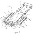
- FIG. 1is a partially exploded view of a first embodiment of the disk drive carrier of the present invention.
- FIG. 2is a partially exploded view of a second embodiment of the disk drive carrier of the present invention.
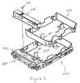
- FIG. 3is a partially exploded view of an embodiment of the disk drive bay of the present invention.
- the disk drive carriercomprises a frame that has a base, a first arm coupled to the base, and a second arm coupled to the base.
- the carrierfurther includes a handle that is coupled to the base, a first slide rail that is coupled to the first arm, and a second slide rail that is coupled to the second arm.
- the disk drive baycomprises a plate, which has a first side and a second side. The first side is oriented substantially parallel to the second side.
- a first wallis coupled to the first side of the plate, and a second wall is coupled to the second side of the plate. The first and second walls each have grooves for receiving the disk drive carrier's slide rails.
- disk drive carrier 100comprises frame 101 and handle 110 .
- Frame 101includes base 102 , first arm 103 , and second arm 104 .
- base 102includes upper member 105 and lower member 106 .
- upper member 105is an integrated, U-shaped, rigid support structure that includes shelf 107 , first arm 103 and second arm 104 .
- Lower member 106is an integrated, U-shaped, rigid support structure that is coupled at each end to upper member 105 , e.g., by rivets 108 and 192 .
- upper member 105is made from sheet metal and lower member 106 is made from stainless steel.
- Handle 110is positioned between upper member 105 and lower member 106 of base 102 .
- Handle 110includes first end 109 and second end 111 .
- End 109includes pawl 112
- end 111includes pin 113 and mechanical lever or latch 114 .
- Pin 113which is coupled to both upper member 105 and lower member 106 , enables handle 110 to rotate from an open position to a closed position.
- rib 115 of pawl 112passes through aperture 116 , which is formed in arm 103
- handle 110is locked into the closed position—as shown here.
- mechanical latch 114can engage an aperture formed in the side of a drive bay to lock disk drive carrier 100 to the drive bay.
- Handle 110may be released from the closed position by squeezing pawl 112 and shoulder 117 , which will cause rib 115 to slip below aperture 116 , enabling pawl 112 to disengage from aperture 116 . Releasing pawl 112 from aperture 116 , and releasing mechanical latch 114 from its corresponding drive bay socket, enables disk drive carrier 100 to be removed from a disk drive bay.
- handle 110comprises a one piece integrated structure formed from a high strength engineering plastic, such as a polycarbonate.
- Disk drive carrier 100further includes first slide rail 118 , which is coupled to arm 103 , and second slide rail 119 , which is coupled to arm 104 .
- Rails 118 and 119will slide into grooves formed in drive bay side walls, when carrier 100 is inserted into a drive bay. Inserting these rails into such grooves will help reduce RVI that could otherwise occur.
- Rails 118 and 119are preferably made from a high density polymer, e.g., a polyamide based engineering plastic like those available from BASF Aktiengesellschaft under the trademark Ultramid®. Although such materials are preferred, rails 118 and 119 may be made from other materials of equal hardness that have shock absorbing properties and that are relatively slick, which enables the rails to easily slide along drive bay grooves—providing excellent ergonomic feel.
- rails 118 and 119includes openings 120 , 121 and 122 , 123 , respectively. These openings enable screws (e.g., screws 124 - 127 ) to pass through the rails, and through matching orifices formed in arms 103 and 104 , for engagement with a disk drive that may be attached to carrier 100 .
- the disk drivein essence, contributes part of the support structure for the disk drive carrier.
- the disk driveBy using the disk drive in this way, such a design reduces the size of the disk drive carrier/disk drive assembly. This, in turn, enables a reduction in the size of the disk drive bay used to store multiple drives.
- EMI/RVI/ESD spring 150may be positioned between first slide rail 118 and first arm 103 to block electromagnetic emissions and protect against electrostatic discharge.
- spring 150is coupled to arm 103 and rail 118 by inserting projecting members 151 and 152 , formed on arm 103 , through apertures 153 and 154 , formed in spring 150 , for engagement with slots 155 and 156 , formed in rail 118 .
- slots 155 and 156include flexible tabs that snap onto projecting members 151 and 152 to connect rail 118 to arm 103 , binding spring 150 in between them.
- flexible tabs, positioned within slots 157 and 158 , formed on rail 119engage projecting members 193 and 194 , formed on arm 104 , to connect rail 119 to arm 104 .
- EMI/RVI/ESD spring 150includes bent flexible sections 181 , 182 and 183 . Because slide rail 118 contacts spring 150 underneath those sections, they will contact a drive bay side wall, when the carrier is inserted in a drive bay. The flexible nature of those sections ensures good contact with the drive bay side wall, which enables electrostatic discharge from the carrier assembly to the system chassis ground. By grounding out ESD under normal operating conditions, this design will eliminate data errors that such ESD might otherwise cause.
- EMI/RVI/ESD spring 150is preferably made from stainless steel, but may be made from other noncorrosive materials that provide the desired flexibility and electrical characteristics.
- carrier 100When a disk drive is not attached to disk drive carrier 100 , carrier 100 includes air baffle 160 .
- Baffle 160includes base 161 , first side 162 , and second side 163 .
- screws 124 - 127will pass through rails 118 and 119 and through arms 103 and 104 for attachment to sides 162 and 163 , connecting the arms to the baffle.
- air baffle 160is made from an engineering thermoplastic, such as a polycarbonate or polycarbonate blend.
- disk drive carrier 100is grounded to the chassis with five grounding clips, e.g., clips 190 and 191 , which are formed in lower member 106 .
- Grounding clips 190 and 191may be made from an electrically conductive material that has spring like characteristics, such as stainless steel. Such clips form a spring loaded arc that compresses when pressure is applied to their surface.
- clips 190 and 191will either contact a drive bay surface or an adjacent carrier and compress—causing an electromechanical connection. That connection may provide additional stability to the drive.
- the electromechanical connectionprovides a low insertion force ground for carrier 100 and an attached disk drive, as carrier 100 is being inserted into the drive bay and before a disk drive connector mates with a high speed back plane. Grounding the carrier before contact with the back plane provides a conductive path that ensures EMI suppression.
- FIG. 1The embodiment of the hot swap disk drive carrier of the present invention, which is shown in FIG. 1, is especially designed to receive a 1 inch disk drive.
- FIG. 2illustrates a second embodiment of the hot swap disk drive carrier of the present invention to accommodate a 1.6 inch disk drive.
- This embodimentincludes similar components and features to those shown in FIG. 1, but additionally includes a second air baffle 270 and carrier extension 283 .
- Baffle 270 and extension 283enable carrier 200 to be used in systems that accommodate a thicker drive by increasing the thickness of front portion 284 of carrier 200 and the thickness of the baffle.
- second baffle 270is identical to first baffle 260 .
- Second baffle 270can be nested inside, and locked to, baffle 260 by rotating baffle 270 1800 degrees from the orientation of baffle 260 , dropping baffle 270 onto baffle 260 and locking the baffles together by inserting clips 285 and 286 , formed on baffle 260 , through slots 287 and 288 , formed on baffle 270 .
- Carrier extension 283may be attached to shelf 207 of frame 202 by passing screw 289 through aperture 247 for engagement with a corresponding slot formed on one end of shelf 207 , and by sliding a hook, formed within slot 248 of extension 283 , into slot 249 , formed on the other end of shelf 207 .
- FIG. 3illustrates an embodiment of the disk drive bay of the present invention.
- Drive bay 300can receive several 5.25 inch disk drives, which preferably include a standard hot swap connection.
- Drive bay 300includes plate 301 , which has first side 302 and second side 303 .
- First side 302is oriented substantially parallel to second side 303 .
- First wall 304is coupled to side 302 of plate 300 .
- wall 304includes five grooves 305 for receiving disk drive carrier slide rails positioned on one side of the disk drives.
- Second wall 306is coupled to side 303 of plate 300 .
- Wall 306also includes five grooves 307 for receiving disk drive carrier slide rails positioned on the opposite side of the disk drives.
- Plate 301is preferably formed from sheet metal and walls 304 and 306 each preferably comprise extruded aluminum.
- Wall 304includes apertures 308 for receiving a mechanical lever or latch that is formed on a disk drive carrier handle. As explained above, when the disk drive carrier of the present invention is inserted into such a drive bay, the mechanical latch that is formed on one end of the carrier handle will lock into aperture 308 .
- Drive bay 300also includes second plate 309 .
- Plate 309like plate 301 , may be made from sheet metal.
- Plate 309is connected to walls 304 and 306 and includes contact surface 310 , for contacting grounding clips that are located on a disk drive carrier, and bent strip 312 .
- Bent strip 312includes apertures 313 , which permit light to pass through them from the space formed between second wall 306 and an overlying section of sheet metal, while ensuring EMI suppression. Such light may be generated by LEDs positioned within that space for providing system status information.
- the above described plates and wallsmay be coupled together using various types of connectors, e.g., rivets 321 - 324 .
- First foam gasket 314is placed over strip 312 .
- Gasket 314preferably includes an electrically conductive woven fabric, which performs an EMI/ESD blocking function.
- Second and third foam gaskets 315 and 316will be placed on interior surface 317 of plate 301 .
- Gaskets 315 and 316also preferably include an electrically conductive woven fabric, which performs an EMI/ESD blocking function.
- LED cover 318may be placed over gasket 314 , primarily for aesthetic reasons. Tab 319 of cover 318 slips into slot 320 of plate 301 , and a corresponding tab on the other end of cover 318 slips into corresponding slot 325 of plate 309 to connect cover 318 to drive bay 300 . Light will shine through plastic coverings 326 , and grooves 327 will enable carrier rails to slide over cover 318 to reach wall 306 .
- the drive bay of the present inventionaccommodates five 1 inch disk drives, other embodiments may handle more or less drives and may handle 1.6 inch drives instead of 1 inch drives.
- the drive bay of the present inventionmay be used in rack mounted chassis for entry level systems (e.g., low profile systems having a single disk drive and other systems with four or less drives) through high end systems that may accommodate twelve or more disk drives.
- Such a storage assemblyenables a low cost hot swap capable disk drive carrier/drive bay system that reduces RVI and suppresses EMI and ESD.
- This combinationyields a cost effective design for storing one or more high speed, high density, disk drives in a relatively small volumetric space.
Landscapes
- Engineering & Computer Science (AREA)
- Microelectronics & Electronic Packaging (AREA)
- Casings For Electric Apparatus (AREA)
Abstract
Description
Claims (16)
Priority Applications (1)
| Application Number | Priority Date | Filing Date | Title |
|---|---|---|---|
| US09/633,484US6421236B1 (en) | 2000-08-07 | 2000-08-07 | Hot swap disk drive carrier and disk drive bay |
Applications Claiming Priority (1)
| Application Number | Priority Date | Filing Date | Title |
|---|---|---|---|
| US09/633,484US6421236B1 (en) | 2000-08-07 | 2000-08-07 | Hot swap disk drive carrier and disk drive bay |
Publications (1)
| Publication Number | Publication Date |
|---|---|
| US6421236B1true US6421236B1 (en) | 2002-07-16 |
Family
ID=24539814
Family Applications (1)
| Application Number | Title | Priority Date | Filing Date |
|---|---|---|---|
| US09/633,484Expired - LifetimeUS6421236B1 (en) | 2000-08-07 | 2000-08-07 | Hot swap disk drive carrier and disk drive bay |
Country Status (1)
| Country | Link |
|---|---|
| US (1) | US6421236B1 (en) |
Cited By (84)
| Publication number | Priority date | Publication date | Assignee | Title |
|---|---|---|---|---|
| US20020094713A1 (en)* | 2001-01-17 | 2002-07-18 | Gough Gerald Ronald | Removable media drives |
| US20020195913A1 (en)* | 2001-05-31 | 2002-12-26 | Sony Computer Entertainment Inc. | Mountable unit loading/unloading mechanism and plate unit |
| US6565167B1 (en)* | 2001-07-06 | 2003-05-20 | Apple Computer, Inc. | Removable computer core with retractable handle mechanism |
| US6592087B2 (en)* | 2001-01-19 | 2003-07-15 | Schneider Electric Industries Sa | Mounting assembly for detection device |
| US20030161118A1 (en)* | 2002-02-28 | 2003-08-28 | Netezza Corporation | Front panel serving as extraction lever for circuit sled mount |
| US6661651B1 (en)* | 2001-12-11 | 2003-12-09 | Hewlett-Packard Development Company, L.P. | Mounting of data storage devices with compliant storage module covers |
| US6659292B2 (en)* | 2001-01-17 | 2003-12-09 | Sun Microsystems, Inc. | Rack mountable systems |
| US6661677B1 (en) | 2002-08-12 | 2003-12-09 | Sun Microsystems, Inc. | Disc drive cage |
| US20040012921A1 (en)* | 2002-07-16 | 2004-01-22 | Fujitsu Limited | Module mounting/removing mechanism and disk array |
| US20050047075A1 (en)* | 2003-08-26 | 2005-03-03 | Roesner Arlen L. | Drive loading system |
| US20050063152A1 (en)* | 2003-09-24 | 2005-03-24 | Chen Yun Lung | Mounting apparatus for data storage device |
| US20050073809A1 (en)* | 2003-03-27 | 2005-04-07 | Lin-Wei Chang | Drawer for digital data storage device |
| US20050121581A1 (en)* | 2003-12-09 | 2005-06-09 | Hon Hai Precision Industry Co., Ltd. | Mounting apparatus for storage devices |
| US20050174730A1 (en)* | 2004-02-05 | 2005-08-11 | Chao-Jung Chen | Vibration-proof removable module |
| US6965516B1 (en)* | 2004-05-21 | 2005-11-15 | Shu-Fen Lin | Mini case for computer |
| US20050270737A1 (en)* | 2004-06-07 | 2005-12-08 | Sun Microsystems, Inc. | Drive carrier |
| US20060021774A1 (en)* | 2004-07-30 | 2006-02-02 | Tatung Co., Ltd. | Shell structure for server |
| US20060034048A1 (en)* | 2004-08-11 | 2006-02-16 | Hon Hai Precision Industry Co., Ltd. | Mounting apparatus for storage device |
| US20070030639A1 (en)* | 2005-08-08 | 2007-02-08 | Inventec Corporation | Grounding part of hard disk against EMI and shock |
| US20070035920A1 (en)* | 2005-08-12 | 2007-02-15 | Hon Hai Precision Industry Co., Ltd. | Mounting apparatus for data storage devices |
| US20080055841A1 (en)* | 2006-08-04 | 2008-03-06 | Hon Hai Precision Industry Co., Ltd. | Disk drive carrier assembly |
| US20080157638A1 (en)* | 2006-12-29 | 2008-07-03 | Universal Scientific Industrial Co., Ltd. | Hard disk drive drawer |
| US20080158810A1 (en)* | 2006-12-29 | 2008-07-03 | Universal Scientific Industrial Co., Ltd. | Hard disk drive drawer |
| US20080205026A1 (en)* | 2007-02-26 | 2008-08-28 | International Business Machines Corporation | Electromagnetic Compliance Spring of Drive Carrier |
| US20080288971A1 (en)* | 2007-05-15 | 2008-11-20 | Vincent Lai | Antivibration guide rail for a computer disk drive |
| US20090080165A1 (en)* | 2007-09-20 | 2009-03-26 | International Business Machines Corporation | Mechanically-Assisted Insertion and Removal of Modular Device |
| US20090230279A1 (en)* | 2008-03-14 | 2009-09-17 | Southco, Inc. | Leverage Device and System Using Same |
| US20090279249A1 (en)* | 2008-05-12 | 2009-11-12 | International Business Machines Corporation | Latch for Securing a Hardware Component Into a Component Bay |
| US7626810B1 (en)* | 2007-05-24 | 2009-12-01 | Netapp, Inc. | Apparatus and method for inhibiting high-frequency, electromagnetic interference from non-metallic hard disk drive carriers |
| US20100020438A1 (en)* | 2008-07-24 | 2010-01-28 | Sun Microsystem, Inc. | Multi-dimensional hard disk drive vibration mitigation |
| US7778031B1 (en) | 2009-07-15 | 2010-08-17 | Teradyne, Inc. | Test slot cooling system for a storage device testing system |
| US20100284145A1 (en)* | 2009-05-08 | 2010-11-11 | Hong Fu Jin Precision Industry (Shenzhen) Co., Ltd. | Retaining apparatus for data storage device |
| US7848106B2 (en) | 2008-04-17 | 2010-12-07 | Teradyne, Inc. | Temperature control within disk drive testing systems |
| US20110013355A1 (en)* | 2009-07-17 | 2011-01-20 | Deng-Hsi Chen | Hard Disk Fixing Seat |
| US7890207B2 (en) | 2008-04-17 | 2011-02-15 | Teradyne, Inc. | Transferring storage devices within storage device testing systems |
| US7904211B2 (en) | 2008-04-17 | 2011-03-08 | Teradyne, Inc. | Dependent temperature control within disk drive testing systems |
| US7908029B2 (en) | 2008-06-03 | 2011-03-15 | Teradyne, Inc. | Processing storage devices |
| US7911778B2 (en) | 2008-04-17 | 2011-03-22 | Teradyne, Inc. | Vibration isolation within disk drive testing systems |
| US20110072445A1 (en)* | 2009-09-24 | 2011-03-24 | Dell Products, Lp | Optical Disk Drive with Reduced Noise |
| US7929303B1 (en) | 2010-02-02 | 2011-04-19 | Teradyne, Inc. | Storage device testing system cooling |
| US7932734B2 (en) | 2009-07-15 | 2011-04-26 | Teradyne, Inc. | Individually heating storage devices in a testing system |
| US20110096490A1 (en)* | 2009-10-23 | 2011-04-28 | Dell Products L.P. | Peripheral Device Carrying Apparatus and Systems |
| US7940529B2 (en) | 2009-07-15 | 2011-05-10 | Teradyne, Inc. | Storage device temperature sensing |
| US7945424B2 (en) | 2008-04-17 | 2011-05-17 | Teradyne, Inc. | Disk drive emulator and method of use thereof |
| US7987018B2 (en) | 2008-04-17 | 2011-07-26 | Teradyne, Inc. | Transferring disk drives within disk drive testing systems |
| US7996174B2 (en) | 2007-12-18 | 2011-08-09 | Teradyne, Inc. | Disk drive testing |
| US8041449B2 (en) | 2008-04-17 | 2011-10-18 | Teradyne, Inc. | Bulk feeding disk drives to disk drive testing systems |
| US20110289521A1 (en)* | 2010-05-24 | 2011-11-24 | Hon Hai Precision Industry Co., Ltd. | Disk drive assembly |
| US8102173B2 (en) | 2008-04-17 | 2012-01-24 | Teradyne, Inc. | Thermal control system for test slot of test rack for disk drive testing system with thermoelectric device and a cooling conduit |
| US8116079B2 (en) | 2009-07-15 | 2012-02-14 | Teradyne, Inc. | Storage device testing system cooling |
| US20120140411A1 (en)* | 2010-12-01 | 2012-06-07 | Hon Hai Precision Industry Co., Ltd. | Hard disk drive simulating apparatus |
| US8218256B1 (en) | 2009-10-30 | 2012-07-10 | Western Digital Technologies, Inc. | Disk spindle assembly cartridge |
| US8238099B2 (en) | 2008-04-17 | 2012-08-07 | Teradyne, Inc. | Enclosed operating area for disk drive testing systems |
| US20120229987A1 (en)* | 2011-03-11 | 2012-09-13 | Hon Hai Precision Industry Co., Ltd. | Electronic apparatus with electromagnetic radiation shielding |
| US8270118B1 (en) | 2009-10-30 | 2012-09-18 | Western Digital Technologies, Inc. | Head stack assembly cartridge |
| US8405971B2 (en) | 2007-12-18 | 2013-03-26 | Teradyne, Inc. | Disk drive transport, clamping and testing |
| US8432630B1 (en) | 2010-06-30 | 2013-04-30 | Western Digital Technologies, Inc. | Disk drive component test system |
| US8482915B2 (en) | 2008-04-17 | 2013-07-09 | Teradyne, Inc. | Temperature control within disk drive testing systems |
| US8547123B2 (en) | 2009-07-15 | 2013-10-01 | Teradyne, Inc. | Storage device testing system with a conductive heating assembly |
| US8628239B2 (en) | 2009-07-15 | 2014-01-14 | Teradyne, Inc. | Storage device temperature sensing |
| US8687349B2 (en) | 2010-07-21 | 2014-04-01 | Teradyne, Inc. | Bulk transfer of storage devices using manual loading |
| US20140239145A1 (en)* | 2013-02-22 | 2014-08-28 | Kyocera Document Solutions Inc. | Retaining structure for information recording device and image forming apparatus including retaining structure |
| US20150077921A1 (en)* | 2013-09-18 | 2015-03-19 | Ennoconn Corporation | Grounding member and mounting apparatus for hard disk drive |
| US9001456B2 (en) | 2010-08-31 | 2015-04-07 | Teradyne, Inc. | Engaging test slots |
| US20150123519A1 (en)* | 2013-11-05 | 2015-05-07 | Quanta Computer Inc. | Hard disk assembly |
| US9459312B2 (en) | 2013-04-10 | 2016-10-04 | Teradyne, Inc. | Electronic assembly test system |
| US9779780B2 (en) | 2010-06-17 | 2017-10-03 | Teradyne, Inc. | Damping vibrations within storage device testing systems |
| US20180279496A1 (en)* | 2015-12-25 | 2018-09-27 | Fivetech Technology Inc. | Pull-out aiding device and chassis-wall module with pull-out aiding function |
| US10297289B1 (en) | 2018-03-19 | 2019-05-21 | Seagate Technology Llc | Secure speed loader for drive carriers |
| US10725091B2 (en) | 2017-08-28 | 2020-07-28 | Teradyne, Inc. | Automated test system having multiple stages |
| US10775408B2 (en) | 2018-08-20 | 2020-09-15 | Teradyne, Inc. | System for testing devices inside of carriers |
| US10845410B2 (en) | 2017-08-28 | 2020-11-24 | Teradyne, Inc. | Automated test system having orthogonal robots |
| US10948534B2 (en) | 2017-08-28 | 2021-03-16 | Teradyne, Inc. | Automated test system employing robotics |
| US10983145B2 (en) | 2018-04-24 | 2021-04-20 | Teradyne, Inc. | System for testing devices inside of carriers |
| US11039546B2 (en) | 2015-12-25 | 2021-06-15 | Ting-Jui Wang | Pull-out aiding device and chassis-wall module with pull-out aiding function |
| US11226390B2 (en) | 2017-08-28 | 2022-01-18 | Teradyne, Inc. | Calibration process for an automated test system |
| US11754622B2 (en) | 2020-10-22 | 2023-09-12 | Teradyne, Inc. | Thermal control system for an automated test system |
| US11754596B2 (en) | 2020-10-22 | 2023-09-12 | Teradyne, Inc. | Test site configuration in an automated test system |
| US11867749B2 (en) | 2020-10-22 | 2024-01-09 | Teradyne, Inc. | Vision system for an automated test system |
| US11899042B2 (en) | 2020-10-22 | 2024-02-13 | Teradyne, Inc. | Automated test system |
| US11953519B2 (en) | 2020-10-22 | 2024-04-09 | Teradyne, Inc. | Modular automated test system |
| US20240164048A1 (en)* | 2022-11-15 | 2024-05-16 | Huawei Digital Power Technologies Co., Ltd. | Heat Dissipation Apparatus and Electric Power Device |
| US12007411B2 (en) | 2021-06-22 | 2024-06-11 | Teradyne, Inc. | Test socket having an automated lid |
| US20240397657A1 (en)* | 2023-05-26 | 2024-11-28 | Chenbro Micom Co.,Ltd. | Hard disk tray conducive to automated productions |
Citations (12)
| Publication number | Priority date | Publication date | Assignee | Title |
|---|---|---|---|---|
| US5327323A (en)* | 1992-04-16 | 1994-07-05 | Samsung Electronics Co., Ltd. | Hard disk compatible system including bracket, guide rails, and inteface board |
| US5602717A (en)* | 1994-07-27 | 1997-02-11 | Emc Corporation | Hot-pluggable data storage device having vibration absorbing and mechanical connector alignment |
| US5654873A (en)* | 1996-01-29 | 1997-08-05 | Silicon Graphics, Inc. | Single connector attachment drive sled assembly having light pipe coupled to a rail |
| US5673172A (en)* | 1996-01-05 | 1997-09-30 | Compaq Computer Corporation | Apparatus for electromagnetic interference and electrostatic discharge shielding of hot plug-connected hard disk drives |
| US5751551A (en)* | 1995-11-07 | 1998-05-12 | Sun Microsystems, Inc. | Universal hard drive bracket with shock and vibrational isolation and electrical grounding |
| US5978212A (en)* | 1997-02-28 | 1999-11-02 | Digital Equipment Corporation | Disk drive locking member with handle |
| US6058016A (en)* | 1998-09-10 | 2000-05-02 | International Business Machines Corporation | Direct dock storage device carrier |
| US6067225A (en)* | 1997-08-04 | 2000-05-23 | Sun Microsystems, Inc. | Disk drive bracket |
| US6069789A (en)* | 1996-10-28 | 2000-05-30 | Samsung Electronics Co., Ltd. | Mounting apparatus for auxiliary storage device of computer |
| US6228902B1 (en)* | 1994-03-02 | 2001-05-08 | Exxon Chemical Patents, Inc. | Tacky polymer particle anti-stick additive |
| US6249432B1 (en)* | 1998-03-13 | 2001-06-19 | International Business Machines Corporation | Vibration dampening system for removable hard disk drive carriers |
| US6272010B1 (en)* | 1998-01-27 | 2001-08-07 | Dell Usa, L.P. | Peripheral device mounting apparatus |
- 2000
- 2000-08-07USUS09/633,484patent/US6421236B1/ennot_activeExpired - Lifetime
Patent Citations (12)
| Publication number | Priority date | Publication date | Assignee | Title |
|---|---|---|---|---|
| US5327323A (en)* | 1992-04-16 | 1994-07-05 | Samsung Electronics Co., Ltd. | Hard disk compatible system including bracket, guide rails, and inteface board |
| US6228902B1 (en)* | 1994-03-02 | 2001-05-08 | Exxon Chemical Patents, Inc. | Tacky polymer particle anti-stick additive |
| US5602717A (en)* | 1994-07-27 | 1997-02-11 | Emc Corporation | Hot-pluggable data storage device having vibration absorbing and mechanical connector alignment |
| US5751551A (en)* | 1995-11-07 | 1998-05-12 | Sun Microsystems, Inc. | Universal hard drive bracket with shock and vibrational isolation and electrical grounding |
| US5673172A (en)* | 1996-01-05 | 1997-09-30 | Compaq Computer Corporation | Apparatus for electromagnetic interference and electrostatic discharge shielding of hot plug-connected hard disk drives |
| US5654873A (en)* | 1996-01-29 | 1997-08-05 | Silicon Graphics, Inc. | Single connector attachment drive sled assembly having light pipe coupled to a rail |
| US6069789A (en)* | 1996-10-28 | 2000-05-30 | Samsung Electronics Co., Ltd. | Mounting apparatus for auxiliary storage device of computer |
| US5978212A (en)* | 1997-02-28 | 1999-11-02 | Digital Equipment Corporation | Disk drive locking member with handle |
| US6067225A (en)* | 1997-08-04 | 2000-05-23 | Sun Microsystems, Inc. | Disk drive bracket |
| US6272010B1 (en)* | 1998-01-27 | 2001-08-07 | Dell Usa, L.P. | Peripheral device mounting apparatus |
| US6249432B1 (en)* | 1998-03-13 | 2001-06-19 | International Business Machines Corporation | Vibration dampening system for removable hard disk drive carriers |
| US6058016A (en)* | 1998-09-10 | 2000-05-02 | International Business Machines Corporation | Direct dock storage device carrier |
Cited By (129)
| Publication number | Priority date | Publication date | Assignee | Title |
|---|---|---|---|---|
| US6791828B2 (en)* | 2001-01-17 | 2004-09-14 | Sun Microsystems, Inc. | Removable media drives |
| US6659292B2 (en)* | 2001-01-17 | 2003-12-09 | Sun Microsystems, Inc. | Rack mountable systems |
| US20020094713A1 (en)* | 2001-01-17 | 2002-07-18 | Gough Gerald Ronald | Removable media drives |
| US6592087B2 (en)* | 2001-01-19 | 2003-07-15 | Schneider Electric Industries Sa | Mounting assembly for detection device |
| US20020195913A1 (en)* | 2001-05-31 | 2002-12-26 | Sony Computer Entertainment Inc. | Mountable unit loading/unloading mechanism and plate unit |
| US6888718B2 (en)* | 2001-05-31 | 2005-05-03 | Sony Computer Entertainment Inc. | Mountable unit loading/unloading mechanism and plate unit |
| US6565167B1 (en)* | 2001-07-06 | 2003-05-20 | Apple Computer, Inc. | Removable computer core with retractable handle mechanism |
| US6661651B1 (en)* | 2001-12-11 | 2003-12-09 | Hewlett-Packard Development Company, L.P. | Mounting of data storage devices with compliant storage module covers |
| US20030161118A1 (en)* | 2002-02-28 | 2003-08-28 | Netezza Corporation | Front panel serving as extraction lever for circuit sled mount |
| US6952341B2 (en)* | 2002-07-16 | 2005-10-04 | Fujitsu Limited | Module mounting/removing mechanism and disk array |
| US20040012921A1 (en)* | 2002-07-16 | 2004-01-22 | Fujitsu Limited | Module mounting/removing mechanism and disk array |
| US6661677B1 (en) | 2002-08-12 | 2003-12-09 | Sun Microsystems, Inc. | Disc drive cage |
| US7057890B2 (en)* | 2003-03-27 | 2006-06-06 | Inventec Corporation | Drawer for digital data storage device |
| US20050073809A1 (en)* | 2003-03-27 | 2005-04-07 | Lin-Wei Chang | Drawer for digital data storage device |
| US7583497B2 (en) | 2003-08-26 | 2009-09-01 | Hewlett-Packard Development Company, L.P. | Drive loading system |
| US20050047075A1 (en)* | 2003-08-26 | 2005-03-03 | Roesner Arlen L. | Drive loading system |
| US7006351B2 (en)* | 2003-09-24 | 2006-02-28 | Hon Hai Precision Ind. Co., Ltd | Mounting apparatus for data storage device |
| US20050063152A1 (en)* | 2003-09-24 | 2005-03-24 | Chen Yun Lung | Mounting apparatus for data storage device |
| US20050121581A1 (en)* | 2003-12-09 | 2005-06-09 | Hon Hai Precision Industry Co., Ltd. | Mounting apparatus for storage devices |
| US20050174730A1 (en)* | 2004-02-05 | 2005-08-11 | Chao-Jung Chen | Vibration-proof removable module |
| US7092250B2 (en)* | 2004-02-05 | 2006-08-15 | Quanta Computer, Inc. | Vibration-proof removable module |
| US6965516B1 (en)* | 2004-05-21 | 2005-11-15 | Shu-Fen Lin | Mini case for computer |
| US20050259389A1 (en)* | 2004-05-21 | 2005-11-24 | Shu-Fen Lin | Mini case for computer |
| US7280352B2 (en)* | 2004-06-07 | 2007-10-09 | Sun Microsystems, Inc. | Drive carrier |
| US20050270737A1 (en)* | 2004-06-07 | 2005-12-08 | Sun Microsystems, Inc. | Drive carrier |
| US20060021774A1 (en)* | 2004-07-30 | 2006-02-02 | Tatung Co., Ltd. | Shell structure for server |
| US20060034048A1 (en)* | 2004-08-11 | 2006-02-16 | Hon Hai Precision Industry Co., Ltd. | Mounting apparatus for storage device |
| US7450375B2 (en)* | 2004-08-11 | 2008-11-11 | Hong Fu Jin Precision Industry (Shenzhen) Co., Ltd. | Mounting apparatus for storage device |
| US7221565B2 (en)* | 2005-08-08 | 2007-05-22 | Inventec Corporation | Grounding part of hard disk against EMI and shock |
| US20070030639A1 (en)* | 2005-08-08 | 2007-02-08 | Inventec Corporation | Grounding part of hard disk against EMI and shock |
| US20070035920A1 (en)* | 2005-08-12 | 2007-02-15 | Hon Hai Precision Industry Co., Ltd. | Mounting apparatus for data storage devices |
| US20080055841A1 (en)* | 2006-08-04 | 2008-03-06 | Hon Hai Precision Industry Co., Ltd. | Disk drive carrier assembly |
| US7511953B2 (en)* | 2006-08-04 | 2009-03-31 | Hong Fu Jin Precision Industry (Shenzhen) Co., Ltd. | Disk drive carrier assembly |
| US20080158810A1 (en)* | 2006-12-29 | 2008-07-03 | Universal Scientific Industrial Co., Ltd. | Hard disk drive drawer |
| US20080157638A1 (en)* | 2006-12-29 | 2008-07-03 | Universal Scientific Industrial Co., Ltd. | Hard disk drive drawer |
| US20080205026A1 (en)* | 2007-02-26 | 2008-08-28 | International Business Machines Corporation | Electromagnetic Compliance Spring of Drive Carrier |
| US20080288971A1 (en)* | 2007-05-15 | 2008-11-20 | Vincent Lai | Antivibration guide rail for a computer disk drive |
| US7548417B2 (en)* | 2007-05-15 | 2009-06-16 | In Win Development, Inc. | Antivibration guide rail for a computer disk drive |
| US7626810B1 (en)* | 2007-05-24 | 2009-12-01 | Netapp, Inc. | Apparatus and method for inhibiting high-frequency, electromagnetic interference from non-metallic hard disk drive carriers |
| US7675754B2 (en)* | 2007-09-20 | 2010-03-09 | International Business Machines Corporation | Mechanically-assisted insertion and removal of modular device |
| US20090080165A1 (en)* | 2007-09-20 | 2009-03-26 | International Business Machines Corporation | Mechanically-Assisted Insertion and Removal of Modular Device |
| US7996174B2 (en) | 2007-12-18 | 2011-08-09 | Teradyne, Inc. | Disk drive testing |
| US8467180B2 (en) | 2007-12-18 | 2013-06-18 | Teradyne, Inc. | Disk drive transport, clamping and testing |
| US8549912B2 (en) | 2007-12-18 | 2013-10-08 | Teradyne, Inc. | Disk drive transport, clamping and testing |
| US8405971B2 (en) | 2007-12-18 | 2013-03-26 | Teradyne, Inc. | Disk drive transport, clamping and testing |
| US20090230279A1 (en)* | 2008-03-14 | 2009-09-17 | Southco, Inc. | Leverage Device and System Using Same |
| US8256737B2 (en) | 2008-03-14 | 2012-09-04 | Southco, Inc. | Leverage device and system using same |
| US7890207B2 (en) | 2008-04-17 | 2011-02-15 | Teradyne, Inc. | Transferring storage devices within storage device testing systems |
| US8160739B2 (en) | 2008-04-17 | 2012-04-17 | Teradyne, Inc. | Transferring storage devices within storage device testing systems |
| US7904211B2 (en) | 2008-04-17 | 2011-03-08 | Teradyne, Inc. | Dependent temperature control within disk drive testing systems |
| US8451608B2 (en) | 2008-04-17 | 2013-05-28 | Teradyne, Inc. | Temperature control within storage device testing systems |
| US7911778B2 (en) | 2008-04-17 | 2011-03-22 | Teradyne, Inc. | Vibration isolation within disk drive testing systems |
| US8482915B2 (en) | 2008-04-17 | 2013-07-09 | Teradyne, Inc. | Temperature control within disk drive testing systems |
| US8305751B2 (en) | 2008-04-17 | 2012-11-06 | Teradyne, Inc. | Vibration isolation within disk drive testing systems |
| US8655482B2 (en) | 2008-04-17 | 2014-02-18 | Teradyne, Inc. | Enclosed operating area for storage device testing systems |
| US8238099B2 (en) | 2008-04-17 | 2012-08-07 | Teradyne, Inc. | Enclosed operating area for disk drive testing systems |
| US7848106B2 (en) | 2008-04-17 | 2010-12-07 | Teradyne, Inc. | Temperature control within disk drive testing systems |
| US8140182B2 (en) | 2008-04-17 | 2012-03-20 | Teradyne, Inc. | Bulk feeding disk drives to disk drive testing systems |
| US7945424B2 (en) | 2008-04-17 | 2011-05-17 | Teradyne, Inc. | Disk drive emulator and method of use thereof |
| US7987018B2 (en) | 2008-04-17 | 2011-07-26 | Teradyne, Inc. | Transferring disk drives within disk drive testing systems |
| US8117480B2 (en) | 2008-04-17 | 2012-02-14 | Teradyne, Inc. | Dependent temperature control within disk drive testing systems |
| US8712580B2 (en) | 2008-04-17 | 2014-04-29 | Teradyne, Inc. | Transferring storage devices within storage device testing systems |
| US8102173B2 (en) | 2008-04-17 | 2012-01-24 | Teradyne, Inc. | Thermal control system for test slot of test rack for disk drive testing system with thermoelectric device and a cooling conduit |
| US8095234B2 (en) | 2008-04-17 | 2012-01-10 | Teradyne, Inc. | Transferring disk drives within disk drive testing systems |
| US8041449B2 (en) | 2008-04-17 | 2011-10-18 | Teradyne, Inc. | Bulk feeding disk drives to disk drive testing systems |
| US8023263B2 (en)* | 2008-05-12 | 2011-09-20 | International Business Machines Corporation | Latch for securing a hardware component into a component bay |
| US20090279249A1 (en)* | 2008-05-12 | 2009-11-12 | International Business Machines Corporation | Latch for Securing a Hardware Component Into a Component Bay |
| US7908029B2 (en) | 2008-06-03 | 2011-03-15 | Teradyne, Inc. | Processing storage devices |
| US8086343B2 (en) | 2008-06-03 | 2011-12-27 | Teradyne, Inc. | Processing storage devices |
| US20100020438A1 (en)* | 2008-07-24 | 2010-01-28 | Sun Microsystem, Inc. | Multi-dimensional hard disk drive vibration mitigation |
| US20100284145A1 (en)* | 2009-05-08 | 2010-11-11 | Hong Fu Jin Precision Industry (Shenzhen) Co., Ltd. | Retaining apparatus for data storage device |
| US8009425B2 (en)* | 2009-05-08 | 2011-08-30 | Hong Fu Jin Precision Industry (Shenzhen) Co., Ltd. | Retaining apparatus for data storage device |
| US7778031B1 (en) | 2009-07-15 | 2010-08-17 | Teradyne, Inc. | Test slot cooling system for a storage device testing system |
| US8279603B2 (en) | 2009-07-15 | 2012-10-02 | Teradyne, Inc. | Test slot cooling system for a storage device testing system |
| US8466699B2 (en) | 2009-07-15 | 2013-06-18 | Teradyne, Inc. | Heating storage devices in a testing system |
| US7995349B2 (en) | 2009-07-15 | 2011-08-09 | Teradyne, Inc. | Storage device temperature sensing |
| US7932734B2 (en) | 2009-07-15 | 2011-04-26 | Teradyne, Inc. | Individually heating storage devices in a testing system |
| US7940529B2 (en) | 2009-07-15 | 2011-05-10 | Teradyne, Inc. | Storage device temperature sensing |
| US8116079B2 (en) | 2009-07-15 | 2012-02-14 | Teradyne, Inc. | Storage device testing system cooling |
| US8547123B2 (en) | 2009-07-15 | 2013-10-01 | Teradyne, Inc. | Storage device testing system with a conductive heating assembly |
| US8628239B2 (en) | 2009-07-15 | 2014-01-14 | Teradyne, Inc. | Storage device temperature sensing |
| US7920380B2 (en) | 2009-07-15 | 2011-04-05 | Teradyne, Inc. | Test slot cooling system for a storage device testing system |
| US20110013355A1 (en)* | 2009-07-17 | 2011-01-20 | Deng-Hsi Chen | Hard Disk Fixing Seat |
| US20110072445A1 (en)* | 2009-09-24 | 2011-03-24 | Dell Products, Lp | Optical Disk Drive with Reduced Noise |
| US8724307B2 (en)* | 2009-09-24 | 2014-05-13 | Dell Products, Lp | Optical disk drive with reduced noise |
| US20110096490A1 (en)* | 2009-10-23 | 2011-04-28 | Dell Products L.P. | Peripheral Device Carrying Apparatus and Systems |
| US8199482B2 (en)* | 2009-10-23 | 2012-06-12 | Dell Products L.P. | Peripheral device carrying apparatus and systems |
| US8270118B1 (en) | 2009-10-30 | 2012-09-18 | Western Digital Technologies, Inc. | Head stack assembly cartridge |
| US8432631B1 (en) | 2009-10-30 | 2013-04-30 | Western Digital Technologies, Inc. | Disk spindle assembly cartridge |
| US8544164B1 (en) | 2009-10-30 | 2013-10-01 | Western Digital Technologies, Inc. | Method for test mounting a head stack assembly cartridge |
| US8218256B1 (en) | 2009-10-30 | 2012-07-10 | Western Digital Technologies, Inc. | Disk spindle assembly cartridge |
| US8687356B2 (en) | 2010-02-02 | 2014-04-01 | Teradyne, Inc. | Storage device testing system cooling |
| US7929303B1 (en) | 2010-02-02 | 2011-04-19 | Teradyne, Inc. | Storage device testing system cooling |
| US20110289521A1 (en)* | 2010-05-24 | 2011-11-24 | Hon Hai Precision Industry Co., Ltd. | Disk drive assembly |
| US8432670B2 (en)* | 2010-05-24 | 2013-04-30 | Hon Hai Precision Industry Co., Ltd. | Disk drive assembly |
| US9779780B2 (en) | 2010-06-17 | 2017-10-03 | Teradyne, Inc. | Damping vibrations within storage device testing systems |
| US8432630B1 (en) | 2010-06-30 | 2013-04-30 | Western Digital Technologies, Inc. | Disk drive component test system |
| US8687349B2 (en) | 2010-07-21 | 2014-04-01 | Teradyne, Inc. | Bulk transfer of storage devices using manual loading |
| US8964361B2 (en) | 2010-07-21 | 2015-02-24 | Teradyne, Inc. | Bulk transfer of storage devices using manual loading |
| US9001456B2 (en) | 2010-08-31 | 2015-04-07 | Teradyne, Inc. | Engaging test slots |
| US20120140411A1 (en)* | 2010-12-01 | 2012-06-07 | Hon Hai Precision Industry Co., Ltd. | Hard disk drive simulating apparatus |
| CN102686091A (en)* | 2011-03-11 | 2012-09-19 | 鸿富锦精密工业(深圳)有限公司 | Electronic device |
| US20120229987A1 (en)* | 2011-03-11 | 2012-09-13 | Hon Hai Precision Industry Co., Ltd. | Electronic apparatus with electromagnetic radiation shielding |
| US20140239145A1 (en)* | 2013-02-22 | 2014-08-28 | Kyocera Document Solutions Inc. | Retaining structure for information recording device and image forming apparatus including retaining structure |
| US9103399B2 (en)* | 2013-02-22 | 2015-08-11 | Kyocera Document Solutions Inc. | Retaining structure for information recording device and image forming apparatus including retaining structure |
| US9459312B2 (en) | 2013-04-10 | 2016-10-04 | Teradyne, Inc. | Electronic assembly test system |
| US9172153B2 (en)* | 2013-09-18 | 2015-10-27 | Ennoconn Corporation | Grounding member and mounting apparatus for hard disk drive |
| US20150077921A1 (en)* | 2013-09-18 | 2015-03-19 | Ennoconn Corporation | Grounding member and mounting apparatus for hard disk drive |
| US20150123519A1 (en)* | 2013-11-05 | 2015-05-07 | Quanta Computer Inc. | Hard disk assembly |
| US9176546B2 (en)* | 2013-11-05 | 2015-11-03 | Quanta Computer Inc. | Hard disk assembly |
| US20180279496A1 (en)* | 2015-12-25 | 2018-09-27 | Fivetech Technology Inc. | Pull-out aiding device and chassis-wall module with pull-out aiding function |
| US10827637B2 (en)* | 2015-12-25 | 2020-11-03 | Fivetech Technology Inc. | Pull-out aiding device and chassis-wall module with pull-out aiding function |
| US11039546B2 (en) | 2015-12-25 | 2021-06-15 | Ting-Jui Wang | Pull-out aiding device and chassis-wall module with pull-out aiding function |
| US11226390B2 (en) | 2017-08-28 | 2022-01-18 | Teradyne, Inc. | Calibration process for an automated test system |
| US10845410B2 (en) | 2017-08-28 | 2020-11-24 | Teradyne, Inc. | Automated test system having orthogonal robots |
| US10948534B2 (en) | 2017-08-28 | 2021-03-16 | Teradyne, Inc. | Automated test system employing robotics |
| US10725091B2 (en) | 2017-08-28 | 2020-07-28 | Teradyne, Inc. | Automated test system having multiple stages |
| US10297289B1 (en) | 2018-03-19 | 2019-05-21 | Seagate Technology Llc | Secure speed loader for drive carriers |
| US10983145B2 (en) | 2018-04-24 | 2021-04-20 | Teradyne, Inc. | System for testing devices inside of carriers |
| US10775408B2 (en) | 2018-08-20 | 2020-09-15 | Teradyne, Inc. | System for testing devices inside of carriers |
| US11754622B2 (en) | 2020-10-22 | 2023-09-12 | Teradyne, Inc. | Thermal control system for an automated test system |
| US11754596B2 (en) | 2020-10-22 | 2023-09-12 | Teradyne, Inc. | Test site configuration in an automated test system |
| US11867749B2 (en) | 2020-10-22 | 2024-01-09 | Teradyne, Inc. | Vision system for an automated test system |
| US11899042B2 (en) | 2020-10-22 | 2024-02-13 | Teradyne, Inc. | Automated test system |
| US11953519B2 (en) | 2020-10-22 | 2024-04-09 | Teradyne, Inc. | Modular automated test system |
| US12007411B2 (en) | 2021-06-22 | 2024-06-11 | Teradyne, Inc. | Test socket having an automated lid |
| US20240164048A1 (en)* | 2022-11-15 | 2024-05-16 | Huawei Digital Power Technologies Co., Ltd. | Heat Dissipation Apparatus and Electric Power Device |
| US20240397657A1 (en)* | 2023-05-26 | 2024-11-28 | Chenbro Micom Co.,Ltd. | Hard disk tray conducive to automated productions |
| US12349305B2 (en)* | 2023-05-26 | 2025-07-01 | Chenbro Micom Co., Ltd. | Hard disk tray conducive to automated productions |
Similar Documents
| Publication | Publication Date | Title |
|---|---|---|
| US6421236B1 (en) | Hot swap disk drive carrier and disk drive bay | |
| US6064568A (en) | Computer system with peripheral device carrier | |
| US6535381B2 (en) | Hot swap drawer assembly | |
| US5668696A (en) | Carrier-based mounting structure for computer peripheral chassis | |
| US6751093B1 (en) | Mounting device assembly for data storage device | |
| US7466544B2 (en) | Latching mechanism | |
| US7072177B2 (en) | Mounting mechanism for storage device | |
| US5544006A (en) | Computer chassis having flexible card guide for expansion card insertion and removal | |
| US7362565B2 (en) | Disk drive support system | |
| US6879495B2 (en) | Carrier for disk drive hot swapping | |
| US8456832B1 (en) | Data storage drive carrier | |
| US7755887B2 (en) | Mounting device for disk drive | |
| US7697276B2 (en) | Fixing apparatus for hard disk drive | |
| US7161798B2 (en) | Expansion card retention apparatus | |
| US7841565B2 (en) | Mounting apparatus for data storage devices | |
| US20090101781A1 (en) | Fixing apparatus for hard disk drive | |
| US6272010B1 (en) | Peripheral device mounting apparatus | |
| US20040008497A1 (en) | Cassette housing for printed circuit cards | |
| US11871533B2 (en) | Carrier unit for installing hard disk drive, carrier assembly having the same, and server having the same | |
| WO2001011454A2 (en) | Computer frame structure | |
| CN115454212B (en) | Hard disk support, hard disk assembly and electronic equipment | |
| CN111752347A (en) | Hard Drive Carriers, Hard Drive Tray Components, and Hard Drive Chassis Components | |
| US7057890B2 (en) | Drawer for digital data storage device | |
| US7813136B2 (en) | Server enclosure | |
| US20070153471A1 (en) | Mounting apparatus for data storage device of computer system |
Legal Events
| Date | Code | Title | Description |
|---|---|---|---|
| AS | Assignment | Owner name:INTEL CORPORATION, CALIFORNIA Free format text:ASSIGNMENT OF ASSIGNORS INTEREST;ASSIGNORS:MONTOYA, TOMMY S.;BENNETT, DOUGLAS G.;ROOT, WILLIAM E.;AND OTHERS;REEL/FRAME:011062/0736 Effective date:20000807 | |
| STCF | Information on status: patent grant | Free format text:PATENTED CASE | |
| FEPP | Fee payment procedure | Free format text:PAYOR NUMBER ASSIGNED (ORIGINAL EVENT CODE: ASPN); ENTITY STATUS OF PATENT OWNER: LARGE ENTITY | |
| FPAY | Fee payment | Year of fee payment:4 | |
| FPAY | Fee payment | Year of fee payment:8 | |
| FPAY | Fee payment | Year of fee payment:12 | |
| AS | Assignment | Owner name:INTEL CORPORATION, CALIFORNIA Free format text:CORRECTIVE ASSIGNMENT TO CORRECT THE REMOVE USSN:09001337 AND PATENT NUMBER:6121100 CORRECTED TO SHOW USSN:09633484 AND PATENT NUMBER:6421236 PREVIOUSLY RECORDED ON REEL 011062 FRAME 0736. ASSIGNOR(S) HEREBY CONFIRMS THE ASSIGNMENT;ASSIGNORS:MONTOYA, TOMMY S.;BENNETT, DOUGLAS G.;ROOT, WILLIAM E.;AND OTHERS;REEL/FRAME:033462/0518 Effective date:20000807 |