US6421217B1 - Circuit breaker accessory reset system - Google Patents
Circuit breaker accessory reset systemDownload PDFInfo
- Publication number
- US6421217B1 US6421217B1US09/526,945US52694500AUS6421217B1US 6421217 B1US6421217 B1US 6421217B1US 52694500 AUS52694500 AUS 52694500AUS 6421217 B1US6421217 B1US 6421217B1
- Authority
- US
- United States
- Prior art keywords
- axis
- latch
- trip arm
- pivot
- reset
- Prior art date
- Legal status (The legal status is an assumption and is not a legal conclusion. Google has not performed a legal analysis and makes no representation as to the accuracy of the status listed.)
- Expired - Lifetime
Links
- 230000007246mechanismEffects0.000claimsabstractdescription53
- 230000004907fluxEffects0.000description11
- 230000009471actionEffects0.000description2
- 230000003247decreasing effectEffects0.000description2
- 239000002184metalSubstances0.000description2
- 230000004913activationEffects0.000description1
- 238000010276constructionMethods0.000description1
- 230000009849deactivationEffects0.000description1
- 230000007423decreaseEffects0.000description1
- 230000000694effectsEffects0.000description1
- 238000004519manufacturing processMethods0.000description1
- 239000000463materialSubstances0.000description1
- 230000004048modificationEffects0.000description1
- 238000012986modificationMethods0.000description1
- 239000007787solidSubstances0.000description1
Images


Classifications
- H—ELECTRICITY
- H01—ELECTRIC ELEMENTS
- H01H—ELECTRIC SWITCHES; RELAYS; SELECTORS; EMERGENCY PROTECTIVE DEVICES
- H01H71/00—Details of the protective switches or relays covered by groups H01H73/00 - H01H83/00
- H01H71/10—Operating or release mechanisms
- H01H71/50—Manual reset mechanisms which may be also used for manual release
- H01H71/505—Latching devices between operating and release mechanism
- H—ELECTRICITY
- H01—ELECTRIC ELEMENTS
- H01H—ELECTRIC SWITCHES; RELAYS; SELECTORS; EMERGENCY PROTECTIVE DEVICES
- H01H71/00—Details of the protective switches or relays covered by groups H01H73/00 - H01H83/00
- H01H71/10—Operating or release mechanisms
- H01H71/12—Automatic release mechanisms with or without manual release
- H01H71/24—Electromagnetic mechanisms
- H01H71/32—Electromagnetic mechanisms having permanently magnetised part
- H01H71/321—Electromagnetic mechanisms having permanently magnetised part characterised by the magnetic circuit or active magnetic elements
- H01H71/322—Electromagnetic mechanisms having permanently magnetised part characterised by the magnetic circuit or active magnetic elements with plunger type armature
- H—ELECTRICITY
- H01—ELECTRIC ELEMENTS
- H01H—ELECTRIC SWITCHES; RELAYS; SELECTORS; EMERGENCY PROTECTIVE DEVICES
- H01H83/00—Protective switches, e.g. circuit-breaking switches, or protective relays operated by abnormal electrical conditions otherwise than solely by excess current
- H01H83/20—Protective switches, e.g. circuit-breaking switches, or protective relays operated by abnormal electrical conditions otherwise than solely by excess current operated by excess current as well as by some other abnormal electrical condition
- H01H2083/205—Protective switches, e.g. circuit-breaking switches, or protective relays operated by abnormal electrical conditions otherwise than solely by excess current operated by excess current as well as by some other abnormal electrical condition having shunt or UVR tripping device with integrated mechanical energy accumulator
- H—ELECTRICITY
- H01—ELECTRIC ELEMENTS
- H01H—ELECTRIC SWITCHES; RELAYS; SELECTORS; EMERGENCY PROTECTIVE DEVICES
- H01H83/00—Protective switches, e.g. circuit-breaking switches, or protective relays operated by abnormal electrical conditions otherwise than solely by excess current
- H01H83/20—Protective switches, e.g. circuit-breaking switches, or protective relays operated by abnormal electrical conditions otherwise than solely by excess current operated by excess current as well as by some other abnormal electrical condition
Definitions
- the present inventionrelates to a circuit breaker accessory, and, more particularly, to a reset system for a circuit breaker accessory.
- an accessoryin an exemplary embodiment of the invention, includes a trip arm biased by a spring to pivot in a clockwise direction about a trip arm pivot.
- a latchis arranged to pivot about a latch pivot and has the trip arm acting on a latch surface on the latch to push the latch in a counter clockwise direction about the latch pivot.
- An electromechanical deviceis positioned in the accessory having a plunger that acts on the latch by pulling it such that it is holding with the trip arm. When a signal is provided to the electromechanical device, the plunger is moved allowing the trip arm, being pushed by the stored energy spring, push the latch out of the way and interface the operating mechanism.
- a reset leveris arranged to pivot about the latch pivot.
- the reset leveris configured to interface the operating mechanism, and has a drive portion for interfacing the trip arm for resetting.
- a portion extending from an operating handleinterfaces the reset lever causing it to pivot, wherein the drive portion interfaces the trip arm to drive the trip arm about the trip arm pivot into the latched and ready to operate position.
- This inventionhas many advantages over the prior art, including but not limited to the ability to reduce the quantity of reset force required to reset the accessory and to provide positional tolerance with added reset over-travel within the accessory.
- FIG. 1is an isometric view of a circuit breaker
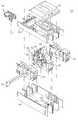
- FIG. 2is an exploded perspective view of a circuit breaker including a trip actuator of the present invention
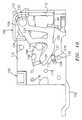
- FIG. 3is an isometric view of the trip actuator and operating mechanism of FIG. 2;
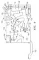
- FIG. 4is a side view depicting the general operation of the circuit breaker operating mechanism of FIG. 3;
- FIG. 5is an isometric view of the trip actuator of FIG. 3 in a released discharged state
- FIG. 6is an isometric front view of the trip actuator of FIG. 3 in the released discharged state having its cover removed and its frame partially cut away;
- FIG. 7is an isometric rear view of the trip actuator of FIG. 3 in the released discharged state having its cover removed and its frame partially cut-away.
- FIG. 8is an isometric view of the trip actuator of FIG. 3 in a released discharged state having a latch removed from the frame;
- FIG. 9is a side view of the trip actuator of FIG. 3 in a latched and ready to operate state
- FIG. 10is a side view of the trip actuator of FIG. 3 in a tripped released state.
- FIG. 11is a side view of the trip actuator of FIG. 3 in a reset state.
- FIG. 12is a side view of the trip actuator of FIG. 3 beyond the reset state.
- FIG. 1A top perspective view of a molded case circuit breaker 20 is provided at FIG. 1 .
- Molded case circuit breaker 20is generally interconnected within a protected circuit between multiple phases of a power source (not shown) at line end 21 and a load to be protected (not shown) at load end 22 .
- Molded case circuit breaker 20includes a housing 24 with a base 25 , a mid cover 26 and a top cover 27 .
- An operating handle 28passes through top cover 27 and interconnects with a circuit breaker operating mechanism 30 .
- a trip actuator 66is generally positioned and configured within mid cover 26 to interface operating mechanism 30 .
- a series of circuit breaker cassettes 32are generally well known and may contain, for example, a rotary type contact structure. Circuit breaker cassettes 32 are seated approximately upstanding within base 25 , and one of the cassettes 32 includes operating mechanism 30 positioned thereon. One cassette 32 is provided for each phase of the electrical distribution circuit. Each cassette 32 includes one or more contact pairs therein for passage of current when the contacts are closed and for preventing passage of current when the contact pairs are opened. Each cassette 32 is commonly operated by a first bar 34 and a second bar 36 that interface with the internal mechanisms of cassettes 32 and with operating mechanism 30 such that operating mechanism 30 operates all cassettes 32 . It is contemplated that the number of phases, or specific type of cassette utilized, can vary according to factors including, but not limited to, the type of load circuit being protected and the type of line input being provided to the circuit breaker 20 .
- circuit breaker operating mechanism 30includes a frame 38 having spaced apart sidewalls.
- An operating handle-yoke 40generally fits over frame 38 .
- Operating handle 28is interconnected with operating handle-yoke 40 .
- Operating mechanism 30includes an operating mechanism cover 42 with a handle opening 44 formed therein allowing operating handle 28 to pass therethrough.
- Handle-yoke 40includes a reset tab 46 depending generally perpendicularly therefrom to allow interface with trip actuator 66 , and more specifically to interact with a reset tab 72 of trip actuator 66 .
- Frame 38includes a secondary latch 52 pivotally secured thereto.
- Secondary latch 52includes a secondary latch tab 50 depending generally perpendicularly therefrom. Secondary latch tab 50 interfaces with a trip paddle 96 extending from trip actuator 66 .
- trip actuator 66Upon assembly, trip actuator 66 is positioned such that the trip paddle 96 is adjacent to latch tab 50 , and a reset tab 72 is adjacent to reset tab 46 . This is generally accomplished by seating trip actuator 66 alongside operating mechanism 30 within mid cover 26 (FIGS. 1 and 2 ).
- FIG. 4shows the operating mechanism 30 in three discrete positions: the “ON” position, the “OFF” position and the “RESET” position.
- trip actuator 66Upon activation of trip actuator 66 , trip paddle 96 will be displaced generally in a forward direction (toward reset tab 72 ) and will contact latch trip tab 50 , displacing tab 50 from the “Latched” position to the “Unlatched” position as shown in FIG. 3 . This will release latch 52 allowing operating mechanism 14 to move from the “ON” position to a “TRIPPED” position (not shown), opening the set of circuit breaker contacts (not shown).
- handle 28In the “TRIPPED” position, handle 28 is located between the “ON” and “OFF” positions shown. Before operating handle 28 may be returned to the quiescent operation position (i.e., “ON”), circuit breaker operating mechanism 30 and trip actuator 66 must be reset. This is accomplished by providing a reset force to operating handle 28 in the counter-clockwise direction against the bias of one or more springs (not shown) to the “RESET” position, thereby moving the secondary latch 52 of operating mechanism 30 from the “Unlatched” position to the “Latched” position. The reset force rotates operating handle 28 causing reset tab 46 , to drive reset tab 72 towards trip paddle 96 and reset trip actuator 66 , as will be described in further detail hereinafter. The reset force can be applied manually or with a charging mechanism (not shown).
- Trip actuator 66includes a frame 100 , an electromechanical device such as a flux shifter 102 , a trip arm 104 , a trip spring 106 , a reset lever 108 , a latch 110 , and a bell alarm lever 152 .
- Frame 100includes a back wall 112 with two sidewalls 114 , 116 depending substantially perpendicular therefrom. The sidewalls 114 , 116 extend substantially parallel to each other, and are joined by a pair of frame pins 118 , 119 that extend from side wall 114 to side wall 116 .
- Frame 100is preferably formed from a single plate of metal.
- a cover 160is positioned generally atop frame 100 , having a front portion 162 supported by frame pin 118 and a rear portion 164 arranged over back wall 112 .
- Trip arm 104is hingedly secured to sidewalls 114 , 116 by a trip arm pivot 120 , which extends from side wall 114 to side wall 116 .
- Trip arm 104includes two hinge portions 122 which accept trip arm pivot 120 , and a hinge support portion 124 that extends between hinge portions 122 .
- Trip arm 104also includes a latch portion 125 that extends downwardly from support portion 124 and along the outside of side wall 116 .
- Latch portion 125is configured with a cut out portion 123 , which is generally provided to reduce the mass of trip arm 104 .
- Trip paddle 96depends substantially perpendicularly latch portion 125 .
- a latch surface 126is formed on an edge of latch portion 125 opposite trip paddle 96 .
- An arcuate cam surface 127is formed on an edge of latch portion 125 opposite reset tab 72 .
- Trip arm 104is preferably formed from a single plate of metal.
- Trip spring 106is shown as a torsion spring disposed around trip arm pivot 120 .
- One end of trip spring 106is secured by back wall 112 of frame 100 , while the other end is positioned beneath hinge support portion 124 of the trip arm 104 .
- Trip spring 106acts to bias trip arm 104 in the clockwise direction, as shown in FIG. 5 .
- Latch 110is formed as a substantially solid shaft having a boss 128 disposed thereon.
- FIG. 8shows latch 110 disasembled.
- a slot 129 formed in boss 128accepts a head 131 of a plunger 130 , which extends from flux shifter 102 .
- the ends of latch 110are pivotally secured to frame sidewalls 114 and 116 by a latch pivot 132 .
- a latch pin 134is secured to an end of latch 110 , and extends from latch 110 through an arcuate slot 136 disposed in side wall 116 .
- Latch pin 134is arranged to interact with the latch surface 126 of trip arm 104 in a manner described hereinbelow.
- Bell alarm lever 152is optionally connected to latch 110 to activate a bell alarm (not shown) when latch 110 is displaced.
- Reset lever 108includes side arms 138 that extend from a central support 140 .
- Side arms 138extend along side walls 114 , 116 and are pivotally secured to side walls 114 , 116 by latch pivot 132 .
- Reset lever 108is biased in the counterclockwise direction about latch, pivot 132 due to a spring 139 having one end attached to a slot 141 in central support 140 and the other end attached to a portion (not shown) of cover 160 proximate to frame pin 118 .
- Latch pin 134extends through an arcuate slot 137 in one side arm 138 .
- Reset tab 72 and a reset roller 142depend substantially perpendicularly from a side arm 138 proximate side wall 116 .
- Reset tab 72 and reset roller 142extend through an arcuate slot 144 formed in sidewall 116 .
- Slot 144has an end 145 that is opposite a side 73 of reset tab 72 .
- Reset roller 142is positioned opposite arcuate cam surface 127 and is configured to roll on cam surface 127 , for example, by being revolvably disposed on a pin (not shown) depending substantially perpendicularly from a side arm 138 .
- Flux shifter 102is an electromechanical device mounted to rear wall 112 of the frame 100 .
- the construction and operation of flux shifter 102is known in the art and is similar in operation to that described in U.S. Pat. No. 5,453,724.
- Flux shifter 102includes plunger 130 , which slidably extends from a body 146 .
- Plunger 130is releasably secured by a magnet (not shown) within body 146 .
- Flux shifter 102is arranged to receive a triggering signal (e.g., a trip signal) from an electrical device (e.g., a trip unit).
- a triggering signale.g., a trip signal
- an electrical devicee.g., a trip unit
- FIG. 9shows trip actuator 66 in a latched and ready to operate state.
- trip spring 106is loaded to bias the trip arm 104 in a clockwise direction about trip arm pivot 120 .
- Latch surface 126 of trip arm 104acts with a force against latch pin 134 that creates a counterclockwise moment about the axis of latch pivot 132 .
- Latch 110is held in an upright position by plunger 130 , and plunger 130 is held in tension by a magnet (not shown) disposed in body 146 of flux shifter 102 .
- a force of plunger 130 on the latch 110creates a clockwise moment about the axis of latch pivot 132 .
- the clockwise moment created by the plunger tensionopposes the counterclockwise moment created by latch surface 126 against latch pin 134 and holds latch 110 in the upright position against the force of trip arm 104 .
- the plunger tension acting on latch 110can generally be much less than the force of trip arm 104 (due to spring 106 ) because of the relationship between the plunger tension, the clockwise moment and its respective moment arm (not shown), and the force of trip arm 104 , the counterclockwise moment and its respective moment arm (not shown). This is described in greater detail in U.S. patent application Ser. No. 09/518,899 now U.S. Pat. No. 6,211,757.
- latch pin 134slides off latch surface 126 , fully releasing trip arm 104 and allowing trip paddle 96 to move towards and into contact with secondary latch tab 50 .
- the rotation of latch 110may also cause a lever, such as a bell alarm lever 152 to move and activate a bell alarm (not shown).
- Trip actuator 66comes to rest in the tripped released state shown in FIG. 10, where latch 110 is prevented from rotating further in the counterclockwise direction by contact with frame pin 119 and trip arm 104 is prevented from rotating further in the clockwise direction by contact with reset tab 72 .
- Trip actuator 66is reset (i.e. placed in the latched and ready to operate state of FIG. 6) by the application of reset force to operating handle 28 .
- reset tab 46 of operating handle 28pushes reset tab 72 of the trip actuator 66 .
- This actioncauses reset lever 108 to pivot in a clockwise direction about latch pivot 132 against the bias of spring 139 .
- the clockwise reset motioncauses reset roller 142 to contact cam surface 127 of trip arm 104 .
- This state (reset state)is shown in FIG. 11 . (Also note the extension of spring 139 as compared to FIG. 9 where there is no reset force.
- roller 142 on cam surface 127rotates trip arm 104 in the counterclockwise direction about pivot 120 against the bias of spring 106 .
- Cam surface 127 and the geometries of trip arm 104 about its pivot 120 , and reset lever 108 about its pivot 132are configured to cause the multiplication of reset driving force applied by roller 142 as force is applied to reset tab 72 .
- This configurationis generally an arcuate shaped cam surface 127 . This results in a driving force that remains constant, or decreases, as reset force is applied to reset tab 72 , even as spring 106 is further charged. Therefore, as reset force is applied, i.e., to operating handle 28 , reset tab 46 pushes reset tab 72 until latch surface 126 is at or beyond latch pin 134 .
- Latch pin 134is at the position of FIG. 8 (i.e., the plunger tension has been reapplied). If the reset force is released, reset lever 108 will be pulled counterclockwise by spring 139 until side 73 of reset tab 72 is stopped by end 145 of slot 144 . The engagement between latch pin 134 and latch surface 126 will hold trip arm 104 against the bias of spring 106 , as described above in the latched state (FIG. 8 ).
- roller 142will continue to apply a driving force to trip arm 104 via cam surface 127 . Due to the arcuate shape of cam surface 127 , continued rotation of trip arm 104 is allowed. Also, due to the shape, the continued driving force by roller 142 will impart less rotation to trip arm 104 about pivot 120 . This reduced rotation of trip arm 104 causes the driving force to be opposed by a constant or reduced bias of spring 106 .
- cam surface 127allowing for decreased rotation of trip unit 104 about pivot 120 also results in a large amount of reset force over-travel, (e.g., operating handle 28 can be rotated to the reset position in FIG. 4 or further to the left) without imparting unwanted motion to other components (e.g., within trip unit 66 , operating mechanism 30 , or both).
- the release of reset force to operating handle 28returns the system to the latched position as described hereinabove.
- the reset system described hereinallows for over-travel in the motion of the reset components with imparting unwanted motion. This over-travel allows for a more compliant interface between actuator 66 and operating mechanism 30 . This is especially effective for overcoming tolerance variation in assembled components. Furthermore, by reducing the opposing force of spring 106 during application of reset force, the overall amount of reset force needed is decreased.
Landscapes
- Physics & Mathematics (AREA)
- Electromagnetism (AREA)
- Breakers (AREA)
Abstract
Description
The present invention relates to a circuit breaker accessory, and, more particularly, to a reset system for a circuit breaker accessory.
It is generally well known in the art of circuit breakers to provide a reset mechanism to reset a tripping device such as an accessory shunt trip or under voltage device. During quiescent operation, (i.e. when the circuit breaker contacts are closed to allow the flow of electrical current) the operating handle of an operating mechanism is in the “ON” position. To stop the current flow manually, the handle may be shifted to the “OFF” position thereby opening the electrical contacts. Upon attainment of a pre-determined condition (trip event), such as ground fault or overload, the operating mechanism of the circuit breaker will release the forces of the mechanism operating springs and release the operating handle to a tripped position between the “ON” position and the “OFF” position. Before the circuit breaker may be turned “ON”, the operating mechanism must be manually reset. This is accomplished by rotating the operating handle beyond the “OFF” position against the bias of the operating mechanism springs, thereby locking the operating mechanism in position.
The same mechanical forces used to direct the operating mechanism from the tripped position to the reset position are used to reset any attached accessories, such as an electronic trip actuator, a shunt trip actuator, auxiliary switch accessory, bell alarm or other type of accessory unit. However, as accessories are generally separate components mounted proximate to the operating mechanism, positional variations at the interface of the accessory and the circuit breaker operating mechanism are possible due to manufacturing tolerances. These positional variations can effect the quantity of reset force translated to the accessory and the range of motion of the provided reset force.
In an exemplary embodiment of the invention, an accessory includes a trip arm biased by a spring to pivot in a clockwise direction about a trip arm pivot. A latch is arranged to pivot about a latch pivot and has the trip arm acting on a latch surface on the latch to push the latch in a counter clockwise direction about the latch pivot. An electromechanical device is positioned in the accessory having a plunger that acts on the latch by pulling it such that it is holding with the trip arm. When a signal is provided to the electromechanical device, the plunger is moved allowing the trip arm, being pushed by the stored energy spring, push the latch out of the way and interface the operating mechanism. To reset the trip arm and the latch, a reset lever is arranged to pivot about the latch pivot. The reset lever is configured to interface the operating mechanism, and has a drive portion for interfacing the trip arm for resetting. Thus, when the operating mechanism is reset, a portion extending from an operating handle interfaces the reset lever causing it to pivot, wherein the drive portion interfaces the trip arm to drive the trip arm about the trip arm pivot into the latched and ready to operate position.
This invention has many advantages over the prior art, including but not limited to the ability to reduce the quantity of reset force required to reset the accessory and to provide positional tolerance with added reset over-travel within the accessory.
FIG. 1 is an isometric view of a circuit breaker;
FIG. 2 is an exploded perspective view of a circuit breaker including a trip actuator of the present invention;
FIG. 3 is an isometric view of the trip actuator and operating mechanism of FIG. 2;
FIG. 4 is a side view depicting the general operation of the circuit breaker operating mechanism of FIG. 3;
FIG. 5 is an isometric view of the trip actuator of FIG. 3 in a released discharged state;
FIG. 6 is an isometric front view of the trip actuator of FIG. 3 in the released discharged state having its cover removed and its frame partially cut away;
FIG. 7 is an isometric rear view of the trip actuator of FIG. 3 in the released discharged state having its cover removed and its frame partially cut-away.
FIG. 8 is an isometric view of the trip actuator of FIG. 3 in a released discharged state having a latch removed from the frame;
FIG. 9 is a side view of the trip actuator of FIG. 3 in a latched and ready to operate state;
FIG. 10 is a side view of the trip actuator of FIG. 3 in a tripped released state.
FIG. 11 is a side view of the trip actuator of FIG. 3 in a reset state; and
FIG. 12 is a side view of the trip actuator of FIG. 3 beyond the reset state.
A top perspective view of a moldedcase circuit breaker 20 is provided at FIG.1. Moldedcase circuit breaker 20 is generally interconnected within a protected circuit between multiple phases of a power source (not shown) atline end 21 and a load to be protected (not shown) atload end 22. Moldedcase circuit breaker 20 includes ahousing 24 with abase 25, amid cover 26 and atop cover 27. Anoperating handle 28 passes throughtop cover 27 and interconnects with a circuitbreaker operating mechanism 30. Atrip actuator 66 is generally positioned and configured withinmid cover 26 tointerface operating mechanism 30.
Referring now to FIG. 2, an exploded view of moldedcase circuit breaker 20 is provided. A series ofcircuit breaker cassettes 32 are generally well known and may contain, for example, a rotary type contact structure.Circuit breaker cassettes 32 are seated approximately upstanding withinbase 25, and one of thecassettes 32 includesoperating mechanism 30 positioned thereon. Onecassette 32 is provided for each phase of the electrical distribution circuit. Eachcassette 32 includes one or more contact pairs therein for passage of current when the contacts are closed and for preventing passage of current when the contact pairs are opened. Eachcassette 32 is commonly operated by afirst bar 34 and asecond bar 36 that interface with the internal mechanisms ofcassettes 32 and withoperating mechanism 30 such thatoperating mechanism 30 operates allcassettes 32. It is contemplated that the number of phases, or specific type of cassette utilized, can vary according to factors including, but not limited to, the type of load circuit being protected and the type of line input being provided to thecircuit breaker 20.
Referring to FIG. 3, circuitbreaker operating mechanism 30 includes aframe 38 having spaced apart sidewalls. An operating handle-yoke 40 generally fits overframe 38.Operating handle 28 is interconnected with operating handle-yoke 40.Operating mechanism 30 includes anoperating mechanism cover 42 with ahandle opening 44 formed therein allowingoperating handle 28 to pass therethrough. Handle-yoke 40 includes areset tab 46 depending generally perpendicularly therefrom to allow interface withtrip actuator 66, and more specifically to interact with areset tab 72 oftrip actuator 66.Frame 38 includes asecondary latch 52 pivotally secured thereto.Secondary latch 52 includes asecondary latch tab 50 depending generally perpendicularly therefrom.Secondary latch tab 50 interfaces with atrip paddle 96 extending fromtrip actuator 66.
Upon assembly,trip actuator 66 is positioned such that thetrip paddle 96 is adjacent tolatch tab 50, and areset tab 72 is adjacent toreset tab 46. This is generally accomplished byseating trip actuator 66 alongsideoperating mechanism 30 within mid cover26 (FIGS.1 and2).
Referring to FIGS. 3 and 4, the operation of the circuitbreaker operating mechanism 30 will be generally described. FIG. 4 shows theoperating mechanism 30 in three discrete positions: the “ON” position, the “OFF” position and the “RESET” position. Upon activation oftrip actuator 66,trip paddle 96 will be displaced generally in a forward direction (toward reset tab72) and will contactlatch trip tab 50, displacingtab 50 from the “Latched” position to the “Unlatched” position as shown in FIG.3. This will releaselatch 52 allowing operating mechanism14 to move from the “ON” position to a “TRIPPED” position (not shown), opening the set of circuit breaker contacts (not shown). In the “TRIPPED” position,handle 28 is located between the “ON” and “OFF” positions shown. Beforeoperating handle 28 may be returned to the quiescent operation position (i.e., “ON”), circuitbreaker operating mechanism 30 andtrip actuator 66 must be reset. This is accomplished by providing a reset force to operatinghandle 28 in the counter-clockwise direction against the bias of one or more springs (not shown) to the “RESET” position, thereby moving thesecondary latch 52 ofoperating mechanism 30 from the “Unlatched” position to the “Latched” position. The reset force rotatesoperating handle 28 causingreset tab 46, to drivereset tab 72 towardstrip paddle 96 and resettrip actuator 66, as will be described in further detail hereinafter. The reset force can be applied manually or with a charging mechanism (not shown).
Referring now to FIGS. 5-8,trip actuator 66 is shown.Trip actuator 66 includes aframe 100, an electromechanical device such as aflux shifter 102, atrip arm 104, atrip spring 106, areset lever 108, alatch 110, and abell alarm lever 152.Frame 100 includes aback wall 112 with twosidewalls sidewalls side wall 114 toside wall 116.Frame 100 is preferably formed from a single plate of metal. Acover 160 is positioned generally atopframe 100, having afront portion 162 supported byframe pin 118 and arear portion 164 arranged overback wall 112.
Referring still to FIGS. 5-8, and also to FIGS. 9 and 10, trip and reset action of thetrip actuator 66 will be described. FIG. 9 showstrip actuator 66 in a latched and ready to operate state. In this state,trip spring 106 is loaded to bias thetrip arm 104 in a clockwise direction abouttrip arm pivot 120.Latch surface 126 oftrip arm 104 acts with a force againstlatch pin 134 that creates a counterclockwise moment about the axis oflatch pivot 132.
When a trip (triggering) signal is provided toflux shifter 102, the coil (not shown) influx shifter 102 shunts out the magnetic circuit, releasingplunger 130. With the plunger tension removed,trip arm 104 will drivelatch pin 134, causinglatch 110 to rotate counterclockwise aboutlatch pivot 132. Aslatch 110 andtrip arm 104 rotate about theirrespective pivots latch pin 134 slides offlatch surface 126, fully releasingtrip arm 104 and allowingtrip paddle 96 to move towards and into contact withsecondary latch tab 50. The rotation oflatch 110 may also cause a lever, such as abell alarm lever 152 to move and activate a bell alarm (not shown). Movement ofsecondary latch tab 50trips operating mechanism 30, as described with reference to FIG. 4 hereinabove.Trip actuator 66 comes to rest in the tripped released state shown in FIG. 10, wherelatch 110 is prevented from rotating further in the counterclockwise direction by contact withframe pin 119 andtrip arm 104 is prevented from rotating further in the clockwise direction by contact withreset tab 72. Note the movement oflatch pin 134 withinslot 136 in the counterclockwise direction (as viewed in FIGS. 8 and 9) due to the release of plunger tension (e.g., due to the deactivation of the magnet within flux shifter102).
The driving force ofroller 142 oncam surface 127 rotatestrip arm 104 in the counterclockwise direction aboutpivot 120 against the bias ofspring 106.Cam surface 127 and the geometries oftrip arm 104 about itspivot 120, and resetlever 108 about itspivot 132 are configured to cause the multiplication of reset driving force applied byroller 142 as force is applied to resettab 72. This configuration is generally an arcuate shapedcam surface 127. This results in a driving force that remains constant, or decreases, as reset force is applied to resettab 72, even asspring 106 is further charged. Therefore, as reset force is applied, i.e., to operatinghandle 28, resettab 46 pushes resettab 72 untillatch surface 126 is at or beyondlatch pin 134.Latch pin 134 is at the position of FIG. 8 (i.e., the plunger tension has been reapplied). If the reset force is released,reset lever 108 will be pulled counterclockwise byspring 139 until side73 ofreset tab 72 is stopped by end145 ofslot 144. The engagement betweenlatch pin 134 andlatch surface 126 will holdtrip arm 104 against the bias ofspring 106, as described above in the latched state (FIG.8).
If, on the other hand, and referring now to FIG. 12, reset force is continued whenlatch surface 126 is at or beyond latch pin134 (i.e., beyond the reset state),roller 142 will continue to apply a driving force to triparm 104 viacam surface 127. Due to the arcuate shape ofcam surface 127, continued rotation oftrip arm 104 is allowed. Also, due to the shape, the continued driving force byroller 142 will impart less rotation to triparm 104 aboutpivot 120. This reduced rotation oftrip arm 104 causes the driving force to be opposed by a constant or reduced bias ofspring 106.
The shape ofcam surface 127 allowing for decreased rotation oftrip unit 104 aboutpivot 120 also results in a large amount of reset force over-travel, (e.g., operatinghandle 28 can be rotated to the reset position in FIG. 4 or further to the left) without imparting unwanted motion to other components (e.g., withintrip unit 66,operating mechanism 30, or both). The release of reset force to operating handle28 returns the system to the latched position as described hereinabove.
The reset system described herein allows for over-travel in the motion of the reset components with imparting unwanted motion. This over-travel allows for a more compliant interface betweenactuator 66 andoperating mechanism 30. This is especially effective for overcoming tolerance variation in assembled components. Furthermore, by reducing the opposing force ofspring 106 during application of reset force, the overall amount of reset force needed is decreased.
While the invention has been described with reference to a preferred embodiment, it will be understood by those skilled in the art that various changes may be made and equivalents may be substituted for elements thereof without departing from the scope of the invention. In addition, many modifications may be made to adapt a particular situation or material to the teachings of the invention without departing from the essential scope thereof. Therefore, it is intended that the invention not be limited to the particular embodiment disclosed as the best mode contemplated for carrying out this invention, but that the invention will include all embodiments falling within the scope of the appended claims.
Claims (20)
1. An accessory for interfacing an operating mechanism in a circuit breaker, the accessory comprising:
a trip arm biased to pivot in a first direction about a first axis;
a latch arranged to pivot about a second axis, said trip arm acting on said latch in a second direction about said second axis;
an electromechanical device including a plunger, said plunger acting on said latch in said first direction about said second axis;
a reset lever arranged to pivot about said second axis, said reset lever configured for interfacing said operating mechanism and for interfacing said trip arm;
wherein providing a signal to said electromechanical device releases said plunger to allow said trip arm to pivot in said first direction about said first axis and actuate the operating mechanism; and
wherein resetting the operating mechanism interfaces said reset lever and pivots said reset lever in said first direction about said second axis, and interfacing said trip arm and pivoting said trip arm about said first axis in the second direction.
2. The accessory as inclaim 1 , said resetting of the operating mechanism accomplished by a reset force, said reset force transferring a drive force to said trip arm in said first direction about said second axis.
3. The accessory as inclaim 2 , wherein said trip arm includes a cam surface formed thereon for being contacted by said reset lever.
4. The accessory as inclaim 3 , wherein said cam surface is configured such said drive force does not increase when said reset lever travels in said first direction about said second axis.
5. The accessory as inclaim 3 , wherein said cam surface is configured such said drive force remains constant when said reset lever travels in said first direction about said second axis.
6. The accessory as inclaim 3 , wherein said cam surface is configured such said drive force does not increase when said reset lever travels in said first direction about said second axis.
7. The accessory as inclaim 3 , wherein said cam surface is arcuate, said drive portion acting on said cam surface such that said drive force when said reset lever commences pivot in said first direction about said second axis is the maximum drive force.
8. The accessory as inclaim 1 , further including:
a frame including first and second sidewalls, said trip arm being pivotally attached to said first sidewall at said first axis, said reset lever being pivotally attached to said first sidewall at said second axis, and said latch being pivotally attached to said first sidewall at said second axis.
9. The accessory as inclaim 8 , wherein said electromechanical device is mounted to said frame.
10. The accessory as inclaim 8 wherein said trip arm includes a latch surface, further wherein said latch is pivotally attached to said first and second sidewalls at said first axis, an end of said latch proximate said first sidewall includes a latch pin extending therefrom, said latch surface acting on said latch pin, said latch further including a boss disposed thereon, said boss having a slot formed therein for accepting said plunger.
11. The accessory ofclaim 10 , further comprising a first spring for providing a bias to said trip arm in said first direction about said first axis, wherein said trip arm includes:
first and second hinge portions, said first hinge portion being pivotally disposed to said first sidewall and said second hinge portion being pivotally attached to said second sidewall;
a support portion extending from said first hinge portion to said second hinge portion, said first spring providing said bias as said support portion; and
a latch portion extending from said support portion and along said first sidewall, said latch portion including said latch surface formed thereon and a latch tab extending therefrom, said latch tab for actuating the operating mechanism.
12. The accessory as inclaim 11 , further wherein said reset lever includes a first side arm pivotally secured to said first sidewall at said second axis, a second side arm pivotally secured to said second sidewall at said second axis, a central support extending from said first sidearm to said second sidearm, and a second spring disposed between a slot on said central portion and a point supported by said frame, said second spring providing a bias to said reset lever in the second direction about said second pivot.
13. The accessory as inclaim 12 , wherein said first sidearm includes a drive portion disposed thereon configured for interfacing said trip arm, and said first sidearm further including a tab portion extending therefrom configured for being interfaced by said operating mechanism.
14. The accessory as inclaim 13 , wherein said drive portion is a low friction device.
15. The accessory as inclaim 14 , wherein said low friction device is a roller.
16. A circuit breaker for protecting a load from one or more predetermined conditions, the circuit breaker including:
a separable contact structure;
an operating mechanism arranged to separate said separable contact structure;
an operating handle interconnected to said operating mechanism; and
a trip actuator arranged proximate said operating handle for actuating said operating mechanism, the trip actuator comprising:
a trip arm biased to pivot in a first direction about a first axis;
a latch arranged to pivot about a second axis, said trip arm acting on said latch in a second direction about said second axis;
an electromechanical device including a plunger, said plunger acting on said latch in said first direction about said second axis;
a reset lever arranged to pivot about said second axis, said reset lever having a tab portion for interfacing said operating handle and a drive portion for interfacing said trip arm;
wherein providing a signal to said electromechanical device upon occurrence said one or more predetermined conditions releases said plunger to allow said trip arm to pivot in said first direction about said first axis and actuate said operating mechanism; and
wherein resetting said operating mechanism interfaces said tab portion to pivot said reset lever in said first direction about said second axis, and said drive portion interfacing said trip arm pivoting said trip arm against about said first axis in the second direction.
17. The circuit breaker as inclaim 16 , wherein said resetting of said operating mechanism is accomplished by a reset force, said reset force transferring a drive force to said trip arm in said first direction about said second axis.
18. The circuit breaker as inclaim 17 , wherein said trip arm includes a surface formed thereon for being contacted by said drive portion, said surface being configured such said drive force does not increase when said reset lever travels in said first direction about said second axis.
19. The circuit breaker as inclaim 17 , wherein said surface is arcuate, said drive portion acting on said surface such that said drive force when said reset lever commences it pivot motion in said first direction about said second axis is the maximum drive force.
20. A trip actuator for interfacing an operating mechanism in a circuit breaker, the trip actuator comprising:
a trip arm biased with a torsional spring to pivot in a first direction about a first axis, said trip arm having a reset surface;
a latch arranged to pivot about a second axis, said trip arm acting on said latch in a second direction about said second axis;
an electromechanical device including a plunger, said plunger acting on said latch in said first direction about said second axis;
a reset lever arranged to pivot about said second axis, said reset lever having a tab portion configured for interfacing said operating mechanism and a roller portion for interfacing said trip arm, and said reset lever biased in said second direction about said second axis;
wherein a reset force is applied to an operating handle on the operating mechanism causing a portion on said handle to interface said tab portion causing said reset lever to pivot in said first direction about said second axis, said reset lever transferring a drive force to said trip arm by the interface of said drive portion to said reset surface, said drive force pivoting said trip arm about said first axis in the second direction; and
wherein said surface is an arcuate configuration such said drive force does not increase when said reset lever travels in said first direction about said second axis.
Priority Applications (4)
| Application Number | Priority Date | Filing Date | Title |
|---|---|---|---|
| US09/526,945US6421217B1 (en) | 2000-03-16 | 2000-03-16 | Circuit breaker accessory reset system |
| PL01365522APL365522A1 (en) | 2000-03-16 | 2001-03-14 | Circuit breaker accessory reset system |
| EP01916660AEP1194939B1 (en) | 2000-03-16 | 2001-03-14 | Circuit breaker accessory reset system |
| PCT/US2001/008194WO2001071751A2 (en) | 2000-03-16 | 2001-03-14 | Circuit breaker accessory reset system |
Applications Claiming Priority (1)
| Application Number | Priority Date | Filing Date | Title |
|---|---|---|---|
| US09/526,945US6421217B1 (en) | 2000-03-16 | 2000-03-16 | Circuit breaker accessory reset system |
Publications (1)
| Publication Number | Publication Date |
|---|---|
| US6421217B1true US6421217B1 (en) | 2002-07-16 |
Family
ID=24099479
Family Applications (1)
| Application Number | Title | Priority Date | Filing Date |
|---|---|---|---|
| US09/526,945Expired - LifetimeUS6421217B1 (en) | 2000-03-16 | 2000-03-16 | Circuit breaker accessory reset system |
Country Status (4)
| Country | Link |
|---|---|
| US (1) | US6421217B1 (en) |
| EP (1) | EP1194939B1 (en) |
| PL (1) | PL365522A1 (en) |
| WO (1) | WO2001071751A2 (en) |
Cited By (14)
| Publication number | Priority date | Publication date | Assignee | Title |
|---|---|---|---|---|
| US20050146825A1 (en)* | 2003-07-23 | 2005-07-07 | Kaszeta William J. | Integrated battery fusing device |
| US20070171011A1 (en)* | 2006-01-23 | 2007-07-26 | Eaton Corporation | Auxiliary switch sub-assembly and electrical switching apparatus employing the same |
| US20070171010A1 (en)* | 2006-01-23 | 2007-07-26 | Eaton Corporation | Electrical switching apparatus and terminal housing therefor |
| US20070194869A1 (en)* | 2006-02-23 | 2007-08-23 | Siemens Energy & Automation, Inc. | Integrated maglatch accessory |
| US20080180932A1 (en)* | 2005-05-13 | 2008-07-31 | Abb Service S.R.L. | Device For Housing and Connection of Accessories For Switches |
| US20110031095A1 (en)* | 2008-04-11 | 2011-02-10 | Abb Technology Ag | Medium voltage circuit breaker with integrated electronic protection unit |
| US20110247785A1 (en)* | 2008-12-29 | 2011-10-13 | Hewlett-Packard Development Company, L.P. | Systems and Method of a Carrier Device for Placement of Thermal Interface Materials |
| US8350168B2 (en) | 2010-06-30 | 2013-01-08 | Schneider Electric USA, Inc. | Quad break modular circuit breaker interrupter |
| US8471654B1 (en)* | 2012-10-25 | 2013-06-25 | General Electric Company | Circuit protection device and flux shifter for a circuit protection device |
| US20140375400A1 (en)* | 2013-06-20 | 2014-12-25 | Schneider Electric Industries Sas | Trip unit and method for producing one such trip device |
| US20150179382A1 (en)* | 2009-01-08 | 2015-06-25 | ABB S.p. A. | Control mechanism for a circuit-breaking device and a circuit-breaking device comprising said mechanism |
| US9281151B2 (en)* | 2013-12-19 | 2016-03-08 | Siemens Industry, Inc. | Lever arm for a shunt trip device |
| US20190096620A1 (en)* | 2017-09-25 | 2019-03-28 | Eaton Corporation | Circuit interrupter, trip deck assembly, and support for switch therefor |
| WO2022206904A1 (en)* | 2021-04-01 | 2022-10-06 | 上海正泰智能科技有限公司 | Quick tripping device and circuit breaker |
Families Citing this family (1)
| Publication number | Priority date | Publication date | Assignee | Title |
|---|---|---|---|---|
| CN106449318B (en)* | 2015-08-04 | 2019-05-24 | 浙江正泰电器股份有限公司 | Breaker tripping mechanism |
Citations (173)
| Publication number | Priority date | Publication date | Assignee | Title |
|---|---|---|---|---|
| US2340682A (en) | 1942-05-06 | 1944-02-01 | Gen Electric | Electric contact element |
| US2719203A (en) | 1952-05-02 | 1955-09-27 | Westinghouse Electric Corp | Circuit breakers |
| US2937254A (en) | 1957-02-05 | 1960-05-17 | Gen Electric | Panelboard unit |
| US3158717A (en) | 1962-07-18 | 1964-11-24 | Gen Electric | Electric circuit breaker including stop means for limiting movement of a toggle linkage |
| US3162739A (en) | 1962-06-25 | 1964-12-22 | Gen Electric | Electric circuit breaker with improved trip means |
| US3197582A (en) | 1962-07-30 | 1965-07-27 | Fed Pacific Electric Co | Enclosed circuit interrupter |
| US3307002A (en) | 1965-02-04 | 1967-02-28 | Texas Instruments Inc | Multipole circuit breaker |
| US3517356A (en) | 1967-07-24 | 1970-06-23 | Terasaki Denki Sangyo Kk | Circuit interrupter |
| US3631369A (en) | 1970-04-27 | 1971-12-28 | Ite Imperial Corp | Blowoff means for circuit breaker latch |
| US3803455A (en) | 1973-01-02 | 1974-04-09 | Gen Electric | Electric circuit breaker static trip unit with thermal override |
| US3883781A (en) | 1973-09-06 | 1975-05-13 | Westinghouse Electric Corp | Remote controlled circuit interrupter |
| US4129762A (en) | 1976-07-30 | 1978-12-12 | Societe Anonyme Dite: Unelec | Circuit-breaker operating mechanism |
| US4144513A (en) | 1977-08-18 | 1979-03-13 | Gould Inc. | Anti-rebound latch for current limiting switches |
| US4158119A (en) | 1977-07-20 | 1979-06-12 | Gould Inc. | Means for breaking welds formed between circuit breaker contacts |
| US4165453A (en) | 1976-08-09 | 1979-08-21 | Societe Anonyme Dite: Unelec | Switch with device to interlock the switch control if the contacts stick |
| US4166988A (en) | 1978-04-19 | 1979-09-04 | General Electric Company | Compact three-pole circuit breaker |
| US4220934A (en) | 1978-10-16 | 1980-09-02 | Westinghouse Electric Corp. | Current limiting circuit breaker with integral magnetic drive device housing and contact arm stop |
| US4255732A (en) | 1978-10-16 | 1981-03-10 | Westinghouse Electric Corp. | Current limiting circuit breaker |
| US4259651A (en) | 1978-10-16 | 1981-03-31 | Westinghouse Electric Corp. | Current limiting circuit interrupter with improved operating mechanism |
| US4263492A (en) | 1979-09-21 | 1981-04-21 | Westinghouse Electric Corp. | Circuit breaker with anti-bounce mechanism |
| US4276527A (en) | 1978-06-23 | 1981-06-30 | Merlin Gerin | Multipole electrical circuit breaker with improved interchangeable trip units |
| US4297663A (en) | 1979-10-26 | 1981-10-27 | General Electric Company | Circuit breaker accessories packaged in a standardized molded case |
| US4301342A (en) | 1980-06-23 | 1981-11-17 | General Electric Company | Circuit breaker condition indicator apparatus |
| US4360852A (en) | 1981-04-01 | 1982-11-23 | Allis-Chalmers Corporation | Overcurrent and overtemperature protective circuit for power transistor system |
| US4368444A (en) | 1980-08-29 | 1983-01-11 | Siemens Aktiengesellschaft | Low-voltage protective circuit breaker with locking lever |
| US4375022A (en) | 1979-03-23 | 1983-02-22 | Alsthom-Unelec | Circuit breaker fitted with a device for indicating a short circuit |
| US4375021A (en) | 1980-01-31 | 1983-02-22 | General Electric Company | Rapid electric-arc extinguishing assembly in circuit-breaking devices such as electric circuit breakers |
| US4376270A (en) | 1980-09-15 | 1983-03-08 | Siemens Aktiengesellschaft | Circuit breaker |
| US4383146A (en) | 1980-03-12 | 1983-05-10 | Merlin Gerin | Four-pole low voltage circuit breaker |
| US4392036A (en) | 1980-08-29 | 1983-07-05 | Siemens Aktiengesellschaft | Low-voltage protective circuit breaker with a forked locking lever |
| US4393283A (en) | 1980-04-10 | 1983-07-12 | Hosiden Electronics Co., Ltd. | Jack with plug actuated slide switch |
| US4401872A (en) | 1981-05-18 | 1983-08-30 | Merlin Gerin | Operating mechanism of a low voltage electric circuit breaker |
| US4409573A (en) | 1981-04-23 | 1983-10-11 | Siemens-Allis, Inc. | Electromagnetically actuated anti-rebound latch |
| US4435690A (en) | 1982-04-26 | 1984-03-06 | Rte Corporation | Primary circuit breaker |
| US4467297A (en) | 1981-05-07 | 1984-08-21 | Merlin Gerin | Multi-pole circuit breaker with interchangeable magneto-thermal tripping unit |
| US4468645A (en) | 1981-10-05 | 1984-08-28 | Merlin Gerin | Multipole circuit breaker with removable trip unit |
| US4470027A (en) | 1982-07-16 | 1984-09-04 | Eaton Corporation | Molded case circuit breaker with improved high fault current interruption capability |
| US4479143A (en) | 1980-12-16 | 1984-10-23 | Sharp Kabushiki Kaisha | Color imaging array and color imaging device |
| US4488133A (en) | 1983-03-28 | 1984-12-11 | Siemens-Allis, Inc. | Contact assembly including spring loaded cam follower overcenter means |
| US4492941A (en) | 1983-02-18 | 1985-01-08 | Heinemann Electric Company | Circuit breaker comprising parallel connected sections |
| US4541032A (en) | 1980-10-21 | 1985-09-10 | B/K Patent Development Company, Inc. | Modular electrical shunts for integrated circuit applications |
| US4546224A (en) | 1982-10-07 | 1985-10-08 | Sace S.P.A. Costruzioni Elettromeccaniche | Electric switch in which the control lever travel is arrested if the contacts become welded together |
| US4550360A (en) | 1984-05-21 | 1985-10-29 | General Electric Company | Circuit breaker static trip unit having automatic circuit trimming |
| US4562419A (en) | 1983-12-22 | 1985-12-31 | Siemens Aktiengesellschaft | Electrodynamically opening contact system |
| US4589052A (en) | 1984-07-17 | 1986-05-13 | General Electric Company | Digital I2 T pickup, time bands and timing control circuits for static trip circuit breakers |
| US4595812A (en) | 1983-09-21 | 1986-06-17 | Mitsubishi Denki Kabushiki Kaisha | Circuit interrupter with detachable optional accessories |
| US4611187A (en) | 1984-02-15 | 1986-09-09 | General Electric Company | Circuit breaker contact arm latch mechanism for eliminating contact bounce |
| US4612430A (en) | 1984-12-21 | 1986-09-16 | Square D Company | Anti-rebound latch |
| US4616198A (en) | 1984-08-14 | 1986-10-07 | General Electric Company | Contact arrangement for a current limiting circuit breaker |
| US4622444A (en) | 1984-07-20 | 1986-11-11 | Fuji Electric Co., Ltd. | Circuit breaker housing and attachment box |
| US4631625A (en) | 1984-09-27 | 1986-12-23 | Siemens Energy & Automation, Inc. | Microprocessor controlled circuit breaker trip unit |
| US4642431A (en) | 1985-07-18 | 1987-02-10 | Westinghouse Electric Corp. | Molded case circuit breaker with a movable electrical contact positioned by a camming spring loaded clip |
| US4644438A (en) | 1983-06-03 | 1987-02-17 | Merlin Gerin | Current-limiting circuit breaker having a selective solid state trip unit |
| US4649247A (en) | 1984-08-23 | 1987-03-10 | Siemens Aktiengesellschaft | Contact assembly for low-voltage circuit breakers with a two-arm contact lever |
| US4658322A (en) | 1982-04-29 | 1987-04-14 | The United States Of America As Represented By The Secretary Of The Navy | Arcing fault detector |
| US4672501A (en) | 1984-06-29 | 1987-06-09 | General Electric Company | Circuit breaker and protective relay unit |
| US4675481A (en) | 1986-10-09 | 1987-06-23 | General Electric Company | Compact electric safety switch |
| US4682264A (en) | 1985-02-25 | 1987-07-21 | Merlin Gerin | Circuit breaker with digital solid-state trip unit fitted with a calibration circuit |
| US4689712A (en) | 1985-02-25 | 1987-08-25 | Merlin Gerin S.A. | Circuit breaker with solid-state trip unit with a digital processing system shunted by an analog processing system |
| US4694373A (en) | 1985-02-25 | 1987-09-15 | Merlin Gerin | Circuit breaker with digital solid-state trip unit with optional functions |
| US4710845A (en) | 1985-02-25 | 1987-12-01 | Merlin Gerin S.A. | Circuit breaker with solid-state trip unit with sampling and latching at the last signal peak |
| US4717985A (en) | 1985-02-25 | 1988-01-05 | Merlin Gerin S.A. | Circuit breaker with digitized solid-state trip unit with inverse time tripping function |
| US4733321A (en) | 1986-04-30 | 1988-03-22 | Merlin Gerin | Solid-state instantaneous trip device for a current limiting circuit breaker |
| US4733211A (en) | 1987-01-13 | 1988-03-22 | General Electric Company | Molded case circuit breaker crossbar assembly |
| US4764650A (en) | 1985-10-31 | 1988-08-16 | Merlin Gerin | Molded case circuit breaker with removable arc chutes and disengageable transmission system between the operating mechanism and the poles |
| US4768007A (en) | 1986-02-28 | 1988-08-30 | Merlin Gerin | Current breaking device with solid-state switch and built-in protective circuit breaker |
| US4780786A (en) | 1986-08-08 | 1988-10-25 | Merlin Gerin | Solid-state trip unit of an electrical circuit breaker with contact wear indicator |
| US4831221A (en) | 1987-12-16 | 1989-05-16 | General Electric Company | Molded case circuit breaker auxiliary switch unit |
| US4870531A (en) | 1988-08-15 | 1989-09-26 | General Electric Company | Circuit breaker with removable display and keypad |
| US4884164A (en) | 1989-02-01 | 1989-11-28 | General Electric Company | Molded case electronic circuit interrupter |
| US4883931A (en) | 1987-06-18 | 1989-11-28 | Merlin Gerin | High pressure arc extinguishing chamber |
| US4884047A (en) | 1987-12-10 | 1989-11-28 | Merlin Gerin | High rating multipole circuit breaker formed by two adjoined molded cases |
| US4900882A (en) | 1987-07-02 | 1990-02-13 | Merlin Gerin | Rotating arc and expansion circuit breaker |
| US4910485A (en) | 1987-10-26 | 1990-03-20 | Merlin Gerin | Multiple circuit breaker with double break rotary contact |
| US4914541A (en) | 1988-01-28 | 1990-04-03 | Merlin Gerin | Solid-state trip device comprising an instantaneous tripping circuit independent from the supply voltage |
| US4916420A (en) | 1987-06-09 | 1990-04-10 | Merlin Gerin | Operating mechanism of a miniature electrical circuit breaker |
| US4916421A (en) | 1987-10-01 | 1990-04-10 | General Electric Company | Contact arrangement for a current limiting circuit breaker |
| US4926282A (en) | 1987-06-12 | 1990-05-15 | Bicc Public Limited Company | Electric circuit breaking apparatus |
| US4935590A (en) | 1988-03-01 | 1990-06-19 | Merlin Gerin | Gas-blast circuit breaker |
| US4937706A (en) | 1987-12-10 | 1990-06-26 | Merlin Gerin | Ground fault current protective device |
| US4939492A (en) | 1988-01-28 | 1990-07-03 | Merlin Gerin | Electromagnetic trip device with tripping threshold adjustment |
| US4943691A (en) | 1988-06-10 | 1990-07-24 | Merlin Gerin | Low-voltage limiting circuit breaker with leaktight extinguishing chamber |
| US4943888A (en) | 1989-07-10 | 1990-07-24 | General Electric Company | Electronic circuit breaker using digital circuitry having instantaneous trip capability |
| US4951019A (en) | 1989-03-30 | 1990-08-21 | Westinghouse Electric Corp. | Electrical circuit breaker operating handle block |
| US4950855A (en) | 1987-11-04 | 1990-08-21 | Merlin Gerin | Self-expansion electrical circuit breaker with variable extinguishing chamber volume |
| US4952897A (en) | 1987-09-25 | 1990-08-28 | Merlin Gerin | Limiting circuit breaker |
| US4958135A (en) | 1987-12-10 | 1990-09-18 | Merlin Gerin | High rating molded case multipole circuit breaker |
| US4965543A (en) | 1988-11-16 | 1990-10-23 | Merin Gerin | Magnetic trip device with wide tripping threshold setting range |
| US4983788A (en) | 1988-06-23 | 1991-01-08 | Cge Compagnia Generale Electtromeccanica S.P.A. | Electric switch mechanism for relays and contactors |
| US5001313A (en) | 1989-02-27 | 1991-03-19 | Merlin Gerin | Rotating arc circuit breaker with centrifugal extinguishing gas effect |
| US5004878A (en) | 1989-03-30 | 1991-04-02 | General Electric Company | Molded case circuit breaker movable contact arm arrangement |
| US5029301A (en) | 1989-06-26 | 1991-07-02 | Merlin Gerin | Limiting circuit breaker equipped with an electromagnetic effect contact fall delay device |
| US5030804A (en) | 1989-04-28 | 1991-07-09 | Asea Brown Boveri Ab | Contact arrangement for electric switching devices |
| US5043688A (en)* | 1990-05-03 | 1991-08-27 | General Electric Company | Actuator-accessory interface unit for molded case circuit interrupter |
| US5057655A (en) | 1989-03-17 | 1991-10-15 | Merlin Gerin | Electrical circuit breaker with self-extinguishing expansion and insulating gas |
| US5077627A (en) | 1989-05-03 | 1991-12-31 | Merlin Gerin | Solid-state trip device for a protective circuit breaker of a three-phase mains system, enabling the type of fault to be detected |
| US5083081A (en) | 1990-03-01 | 1992-01-21 | Merlin Gerin | Current sensor for an electronic trip device |
| US5095183A (en) | 1989-01-17 | 1992-03-10 | Merlin Gerin | Gas-blast electrical circuit breaker |
| US5103198A (en) | 1990-05-04 | 1992-04-07 | Merlin Gerin | Instantaneous trip device of a circuit breaker |
| US5115371A (en) | 1989-09-13 | 1992-05-19 | Merlin Gerin | Circuit breaker comprising an electronic trip device |
| US5120921A (en) | 1990-09-27 | 1992-06-09 | Siemens Energy & Automation, Inc. | Circuit breaker including improved handle indication of contact position |
| US5132865A (en) | 1989-09-13 | 1992-07-21 | Merlin Gerin | Ultra high-speed circuit breaker with galvanic isolation |
| US5138121A (en) | 1989-08-16 | 1992-08-11 | Siemens Aktiengesellschaft | Auxiliary contact mounting block |
| US5140115A (en) | 1991-02-25 | 1992-08-18 | General Electric Company | Circuit breaker contacts condition indicator |
| US5153802A (en) | 1990-06-12 | 1992-10-06 | Merlin Gerin | Static switch |
| US5155315A (en) | 1989-12-11 | 1992-10-13 | Merlin Gerin | Hybrid medium voltage circuit breaker |
| US5166483A (en) | 1990-06-14 | 1992-11-24 | Merlin Gerin | Electrical circuit breaker with rotating arc and self-extinguishing expansion |
| US5172087A (en) | 1992-01-31 | 1992-12-15 | General Electric Company | Handle connector for multi-pole circuit breaker |
| US5178504A (en) | 1990-05-29 | 1993-01-12 | Cge Compagnia Generale Elettromeccanica Spa | Plugged fastening device with snap-action locking for control and/or signalling units |
| US5184717A (en) | 1991-05-29 | 1993-02-09 | Westinghouse Electric Corp. | Circuit breaker with welded contacts |
| US5187339A (en) | 1990-06-26 | 1993-02-16 | Merlin Gerin | Gas insulated high-voltage circuit breaker with pneumatic operating mechanism |
| US5198956A (en) | 1992-06-19 | 1993-03-30 | Square D Company | Overtemperature sensing and signaling circuit |
| US5200724A (en) | 1989-03-30 | 1993-04-06 | Westinghouse Electric Corp. | Electrical circuit breaker operating handle block |
| US5210385A (en) | 1989-07-26 | 1993-05-11 | Merlin Gerin | Low voltage circuit breaker with multiple contacts for high currents |
| US5239150A (en) | 1991-06-03 | 1993-08-24 | Merlin Gerin | Medium voltage circuit breaker with operating mechanism providing reduced operating energy |
| US5260533A (en) | 1991-10-18 | 1993-11-09 | Westinghouse Electric Corp. | Molded case current limiting circuit breaker |
| US5262744A (en) | 1991-01-22 | 1993-11-16 | General Electric Company | Molded case circuit breaker multi-pole crossbar assembly |
| US5280144A (en) | 1991-10-17 | 1994-01-18 | Merlin Gerin | Hybrid circuit breaker with axial blowout coil |
| US5281776A (en) | 1991-10-15 | 1994-01-25 | Merlin Gerin | Multipole circuit breaker with single-pole units |
| US5296664A (en) | 1992-11-16 | 1994-03-22 | Westinghouse Electric Corp. | Circuit breaker with positive off protection |
| US5296660A (en) | 1992-02-07 | 1994-03-22 | Merlin Gerin | Auxiliary shunt multiple contact breaking device |
| US5298874A (en) | 1991-10-15 | 1994-03-29 | Merlin Gerin | Range of molded case low voltage circuit breakers |
| US5300907A (en) | 1992-02-07 | 1994-04-05 | Merlin Gerin | Operating mechanism of a molded case circuit breaker |
| US5310971A (en) | 1992-03-13 | 1994-05-10 | Merlin Gerin | Molded case circuit breaker with contact bridge slowed down at the end of repulsion travel |
| US5313180A (en) | 1992-03-13 | 1994-05-17 | Merlin Gerin | Molded case circuit breaker contact |
| US5317471A (en) | 1991-11-13 | 1994-05-31 | Gerin Merlin | Process and device for setting a thermal trip device with bimetal strip |
| US5331500A (en) | 1990-12-26 | 1994-07-19 | Merlin Gerin | Circuit breaker comprising a card interfacing with a trip device |
| US5334808A (en) | 1992-04-23 | 1994-08-02 | Merlin Gerin | Draw-out molded case circuit breaker |
| US5341191A (en) | 1991-10-18 | 1994-08-23 | Eaton Corporation | Molded case current limiting circuit breaker |
| US5347096A (en) | 1991-10-17 | 1994-09-13 | Merlin Gerin | Electrical circuit breaker with two vacuum cartridges in series |
| US5347097A (en) | 1990-08-01 | 1994-09-13 | Merlin Gerin | Electrical circuit breaker with rotating arc and self-extinguishing expansion |
| US5350892A (en) | 1991-11-20 | 1994-09-27 | Gec Alsthom Sa | Medium tension circuit-breaker for indoor or outdoor use |
| US5357066A (en) | 1991-10-29 | 1994-10-18 | Merlin Gerin | Operating mechanism for a four-pole circuit breaker |
| US5357068A (en) | 1991-11-20 | 1994-10-18 | Gec Alsthom Sa | Sulfur hexafluoride isolating circuit-breaker and use thereof in prefabricated stations, substations, and bays |
| US5357394A (en) | 1991-10-10 | 1994-10-18 | Merlin Gerin | Circuit breaker with selective locking |
| US5361052A (en) | 1993-07-02 | 1994-11-01 | General Electric Company | Industrial-rated circuit breaker having universal application |
| US5373130A (en) | 1992-06-30 | 1994-12-13 | Merlin Gerin | Self-extinguishing expansion switch or circuit breaker |
| US5379013A (en) | 1992-09-28 | 1995-01-03 | Merlin Gerin | Molded case circuit breaker with interchangeable trip units |
| US5424701A (en) | 1994-02-25 | 1995-06-13 | General Electric | Operating mechanism for high ampere-rated circuit breakers |
| US5438176A (en) | 1992-10-13 | 1995-08-01 | Merlin Gerin | Three-position switch actuating mechanism |
| US5440088A (en) | 1992-09-29 | 1995-08-08 | Merlin Gerin | Molded case circuit breaker with auxiliary contacts |
| US5449871A (en) | 1993-04-20 | 1995-09-12 | Merlin Gerin | Operating mechanism of a multipole electrical circuit breaker |
| US5450048A (en) | 1993-04-01 | 1995-09-12 | Merlin Gerin | Circuit breaker comprising a removable calibrating device |
| US5451729A (en) | 1993-03-17 | 1995-09-19 | Ellenberger & Poensgen Gmbh | Single or multipole circuit breaker |
| US5457295A (en) | 1992-09-28 | 1995-10-10 | Mitsubishi Denki Kabushiki Kaisha | Circuit breaker |
| US5467069A (en) | 1993-04-16 | 1995-11-14 | Merlin Gerin | Device for adjusting the tripping threshold of a multipole circuit breaker |
| US5469121A (en) | 1993-04-07 | 1995-11-21 | Merlin Gerin | Multiple current-limiting circuit breaker with electrodynamic repulsion |
| US5475558A (en) | 1991-07-09 | 1995-12-12 | Merlin Gerin | Electrical power distribution device with isolation monitoring |
| US5477016A (en) | 1993-02-16 | 1995-12-19 | Merlin Gerin | Circuit breaker with remote control and disconnection function |
| US5479143A (en) | 1993-04-07 | 1995-12-26 | Merlin Gerin | Multipole circuit breaker with modular assembly |
| US5483212A (en) | 1992-10-14 | 1996-01-09 | Klockner-Moeller Gmbh | Overload relay to be combined with contactors |
| US5485343A (en) | 1994-02-22 | 1996-01-16 | General Electric Company | Digital circuit interrupter with battery back-up facility |
| US5493083A (en) | 1993-02-16 | 1996-02-20 | Merlin Gerin | Rotary control device of a circuit breaker |
| USD367265S (en) | 1994-07-15 | 1996-02-20 | Mitsubishi Denki Kabushiki Kaisha | Circuit breaker for distribution |
| US5504290A (en) | 1993-02-16 | 1996-04-02 | Merlin Gerin | Remote controlled circuit breaker with recharging cam |
| US5504284A (en) | 1993-02-03 | 1996-04-02 | Merlin Gerin | Device for mechanical and electrical lockout of a remote control unit for a modular circuit breaker |
| US5510761A (en) | 1993-01-11 | 1996-04-23 | Klockner Moeller Gmbh | Contact system for a current limiting unit |
| US5512720A (en) | 1993-04-16 | 1996-04-30 | Merlin Gerin | Auxiliary trip device for a circuit breaker |
| US5515018A (en) | 1994-09-28 | 1996-05-07 | Siemens Energy & Automation, Inc. | Pivoting circuit breaker load terminal |
| GB2294811A (en)* | 1994-11-02 | 1996-05-08 | Gen Electric | Electronic trip unit conversion kit for circuit breakers |
| US5519561A (en) | 1994-11-08 | 1996-05-21 | Eaton Corporation | Circuit breaker using bimetal of thermal-magnetic trip to sense current |
| US5534674A (en) | 1993-11-02 | 1996-07-09 | Klockner-Moeller Gmbh | Current limiting contact system for circuit breakers |
| US5534840A (en) | 1993-07-02 | 1996-07-09 | Schneider Electric Sa | Control and/or indicator unit |
| US5534835A (en) | 1995-03-30 | 1996-07-09 | Siemens Energy & Automation, Inc. | Circuit breaker with molded cam surfaces |
| US5534832A (en) | 1993-03-25 | 1996-07-09 | Telemecanique | Switch |
| US5539168A (en) | 1994-03-11 | 1996-07-23 | Klockner-Moeller Gmbh | Power circuit breaker having a housing structure with accessory equipment for the power circuit breaker |
| US5543595A (en) | 1994-02-02 | 1996-08-06 | Klockner-Moeller Gmbh | Circuit breaker with a blocking mechanism and a blocking mechanism for a circuit breaker |
| US5552755A (en) | 1992-09-11 | 1996-09-03 | Eaton Corporation | Circuit breaker with auxiliary switch actuated by cascaded actuating members |
| US5581219A (en) | 1991-10-24 | 1996-12-03 | Fuji Electric Co., Ltd. | Circuit breaker |
| US5604656A (en) | 1993-07-06 | 1997-02-18 | J. H. Fenner & Co., Limited | Electromechanical relays |
| US5608367A (en) | 1995-11-30 | 1997-03-04 | Eaton Corporation | Molded case circuit breaker with interchangeable trip unit having bimetal assembly which registers with permanent heater transformer airgap |
| US5784233A (en) | 1994-01-06 | 1998-07-21 | Schneider Electric Sa | Differential protection device of a power transformer |
| US6127757A (en)* | 1996-03-08 | 2000-10-03 | Bae Systems Electronics Limited | Levitation device |
Family Cites Families (2)
| Publication number | Priority date | Publication date | Assignee | Title |
|---|---|---|---|---|
| US4506246A (en)* | 1983-05-09 | 1985-03-19 | Square D Company | Interlock scheme for high amperage molded case circuit breaker |
| US5453724A (en)* | 1994-05-27 | 1995-09-26 | General Electric | Flux shifter assembly for circuit breaker accessories |
- 2000
- 2000-03-16USUS09/526,945patent/US6421217B1/ennot_activeExpired - Lifetime
- 2001
- 2001-03-14EPEP01916660Apatent/EP1194939B1/ennot_activeExpired - Lifetime
- 2001-03-14PLPL01365522Apatent/PL365522A1/enunknown
- 2001-03-14WOPCT/US2001/008194patent/WO2001071751A2/enactiveApplication Filing
Patent Citations (173)
| Publication number | Priority date | Publication date | Assignee | Title |
|---|---|---|---|---|
| US2340682A (en) | 1942-05-06 | 1944-02-01 | Gen Electric | Electric contact element |
| US2719203A (en) | 1952-05-02 | 1955-09-27 | Westinghouse Electric Corp | Circuit breakers |
| US2937254A (en) | 1957-02-05 | 1960-05-17 | Gen Electric | Panelboard unit |
| US3162739A (en) | 1962-06-25 | 1964-12-22 | Gen Electric | Electric circuit breaker with improved trip means |
| US3158717A (en) | 1962-07-18 | 1964-11-24 | Gen Electric | Electric circuit breaker including stop means for limiting movement of a toggle linkage |
| US3197582A (en) | 1962-07-30 | 1965-07-27 | Fed Pacific Electric Co | Enclosed circuit interrupter |
| US3307002A (en) | 1965-02-04 | 1967-02-28 | Texas Instruments Inc | Multipole circuit breaker |
| US3517356A (en) | 1967-07-24 | 1970-06-23 | Terasaki Denki Sangyo Kk | Circuit interrupter |
| US3631369A (en) | 1970-04-27 | 1971-12-28 | Ite Imperial Corp | Blowoff means for circuit breaker latch |
| US3803455A (en) | 1973-01-02 | 1974-04-09 | Gen Electric | Electric circuit breaker static trip unit with thermal override |
| US3883781A (en) | 1973-09-06 | 1975-05-13 | Westinghouse Electric Corp | Remote controlled circuit interrupter |
| US4129762A (en) | 1976-07-30 | 1978-12-12 | Societe Anonyme Dite: Unelec | Circuit-breaker operating mechanism |
| US4165453A (en) | 1976-08-09 | 1979-08-21 | Societe Anonyme Dite: Unelec | Switch with device to interlock the switch control if the contacts stick |
| US4158119A (en) | 1977-07-20 | 1979-06-12 | Gould Inc. | Means for breaking welds formed between circuit breaker contacts |
| US4144513A (en) | 1977-08-18 | 1979-03-13 | Gould Inc. | Anti-rebound latch for current limiting switches |
| US4166988A (en) | 1978-04-19 | 1979-09-04 | General Electric Company | Compact three-pole circuit breaker |
| US4276527A (en) | 1978-06-23 | 1981-06-30 | Merlin Gerin | Multipole electrical circuit breaker with improved interchangeable trip units |
| US4259651A (en) | 1978-10-16 | 1981-03-31 | Westinghouse Electric Corp. | Current limiting circuit interrupter with improved operating mechanism |
| US4255732A (en) | 1978-10-16 | 1981-03-10 | Westinghouse Electric Corp. | Current limiting circuit breaker |
| US4220934A (en) | 1978-10-16 | 1980-09-02 | Westinghouse Electric Corp. | Current limiting circuit breaker with integral magnetic drive device housing and contact arm stop |
| US4375022A (en) | 1979-03-23 | 1983-02-22 | Alsthom-Unelec | Circuit breaker fitted with a device for indicating a short circuit |
| US4263492A (en) | 1979-09-21 | 1981-04-21 | Westinghouse Electric Corp. | Circuit breaker with anti-bounce mechanism |
| US4297663A (en) | 1979-10-26 | 1981-10-27 | General Electric Company | Circuit breaker accessories packaged in a standardized molded case |
| US4375021A (en) | 1980-01-31 | 1983-02-22 | General Electric Company | Rapid electric-arc extinguishing assembly in circuit-breaking devices such as electric circuit breakers |
| US4383146A (en) | 1980-03-12 | 1983-05-10 | Merlin Gerin | Four-pole low voltage circuit breaker |
| US4393283A (en) | 1980-04-10 | 1983-07-12 | Hosiden Electronics Co., Ltd. | Jack with plug actuated slide switch |
| US4301342A (en) | 1980-06-23 | 1981-11-17 | General Electric Company | Circuit breaker condition indicator apparatus |
| US4368444A (en) | 1980-08-29 | 1983-01-11 | Siemens Aktiengesellschaft | Low-voltage protective circuit breaker with locking lever |
| US4392036A (en) | 1980-08-29 | 1983-07-05 | Siemens Aktiengesellschaft | Low-voltage protective circuit breaker with a forked locking lever |
| US4376270A (en) | 1980-09-15 | 1983-03-08 | Siemens Aktiengesellschaft | Circuit breaker |
| US4541032A (en) | 1980-10-21 | 1985-09-10 | B/K Patent Development Company, Inc. | Modular electrical shunts for integrated circuit applications |
| US4479143A (en) | 1980-12-16 | 1984-10-23 | Sharp Kabushiki Kaisha | Color imaging array and color imaging device |
| US4360852A (en) | 1981-04-01 | 1982-11-23 | Allis-Chalmers Corporation | Overcurrent and overtemperature protective circuit for power transistor system |
| US4409573A (en) | 1981-04-23 | 1983-10-11 | Siemens-Allis, Inc. | Electromagnetically actuated anti-rebound latch |
| US4467297A (en) | 1981-05-07 | 1984-08-21 | Merlin Gerin | Multi-pole circuit breaker with interchangeable magneto-thermal tripping unit |
| US4401872A (en) | 1981-05-18 | 1983-08-30 | Merlin Gerin | Operating mechanism of a low voltage electric circuit breaker |
| US4468645A (en) | 1981-10-05 | 1984-08-28 | Merlin Gerin | Multipole circuit breaker with removable trip unit |
| US4435690A (en) | 1982-04-26 | 1984-03-06 | Rte Corporation | Primary circuit breaker |
| US4658322A (en) | 1982-04-29 | 1987-04-14 | The United States Of America As Represented By The Secretary Of The Navy | Arcing fault detector |
| US4470027A (en) | 1982-07-16 | 1984-09-04 | Eaton Corporation | Molded case circuit breaker with improved high fault current interruption capability |
| US4546224A (en) | 1982-10-07 | 1985-10-08 | Sace S.P.A. Costruzioni Elettromeccaniche | Electric switch in which the control lever travel is arrested if the contacts become welded together |
| US4492941A (en) | 1983-02-18 | 1985-01-08 | Heinemann Electric Company | Circuit breaker comprising parallel connected sections |
| US4488133A (en) | 1983-03-28 | 1984-12-11 | Siemens-Allis, Inc. | Contact assembly including spring loaded cam follower overcenter means |
| US4644438A (en) | 1983-06-03 | 1987-02-17 | Merlin Gerin | Current-limiting circuit breaker having a selective solid state trip unit |
| US4595812A (en) | 1983-09-21 | 1986-06-17 | Mitsubishi Denki Kabushiki Kaisha | Circuit interrupter with detachable optional accessories |
| US4562419A (en) | 1983-12-22 | 1985-12-31 | Siemens Aktiengesellschaft | Electrodynamically opening contact system |
| US4611187A (en) | 1984-02-15 | 1986-09-09 | General Electric Company | Circuit breaker contact arm latch mechanism for eliminating contact bounce |
| US4550360A (en) | 1984-05-21 | 1985-10-29 | General Electric Company | Circuit breaker static trip unit having automatic circuit trimming |
| US4672501A (en) | 1984-06-29 | 1987-06-09 | General Electric Company | Circuit breaker and protective relay unit |
| US4589052A (en) | 1984-07-17 | 1986-05-13 | General Electric Company | Digital I2 T pickup, time bands and timing control circuits for static trip circuit breakers |
| US4622444A (en) | 1984-07-20 | 1986-11-11 | Fuji Electric Co., Ltd. | Circuit breaker housing and attachment box |
| US4616198A (en) | 1984-08-14 | 1986-10-07 | General Electric Company | Contact arrangement for a current limiting circuit breaker |
| US4649247A (en) | 1984-08-23 | 1987-03-10 | Siemens Aktiengesellschaft | Contact assembly for low-voltage circuit breakers with a two-arm contact lever |
| US4631625A (en) | 1984-09-27 | 1986-12-23 | Siemens Energy & Automation, Inc. | Microprocessor controlled circuit breaker trip unit |
| US4612430A (en) | 1984-12-21 | 1986-09-16 | Square D Company | Anti-rebound latch |
| US4717985A (en) | 1985-02-25 | 1988-01-05 | Merlin Gerin S.A. | Circuit breaker with digitized solid-state trip unit with inverse time tripping function |
| US4682264A (en) | 1985-02-25 | 1987-07-21 | Merlin Gerin | Circuit breaker with digital solid-state trip unit fitted with a calibration circuit |
| US4689712A (en) | 1985-02-25 | 1987-08-25 | Merlin Gerin S.A. | Circuit breaker with solid-state trip unit with a digital processing system shunted by an analog processing system |
| US4694373A (en) | 1985-02-25 | 1987-09-15 | Merlin Gerin | Circuit breaker with digital solid-state trip unit with optional functions |
| US4710845A (en) | 1985-02-25 | 1987-12-01 | Merlin Gerin S.A. | Circuit breaker with solid-state trip unit with sampling and latching at the last signal peak |
| US4642431A (en) | 1985-07-18 | 1987-02-10 | Westinghouse Electric Corp. | Molded case circuit breaker with a movable electrical contact positioned by a camming spring loaded clip |
| US4764650A (en) | 1985-10-31 | 1988-08-16 | Merlin Gerin | Molded case circuit breaker with removable arc chutes and disengageable transmission system between the operating mechanism and the poles |
| US4768007A (en) | 1986-02-28 | 1988-08-30 | Merlin Gerin | Current breaking device with solid-state switch and built-in protective circuit breaker |
| US4733321A (en) | 1986-04-30 | 1988-03-22 | Merlin Gerin | Solid-state instantaneous trip device for a current limiting circuit breaker |
| US4780786A (en) | 1986-08-08 | 1988-10-25 | Merlin Gerin | Solid-state trip unit of an electrical circuit breaker with contact wear indicator |
| US4675481A (en) | 1986-10-09 | 1987-06-23 | General Electric Company | Compact electric safety switch |
| US4733211A (en) | 1987-01-13 | 1988-03-22 | General Electric Company | Molded case circuit breaker crossbar assembly |
| US4916420A (en) | 1987-06-09 | 1990-04-10 | Merlin Gerin | Operating mechanism of a miniature electrical circuit breaker |
| US4926282A (en) | 1987-06-12 | 1990-05-15 | Bicc Public Limited Company | Electric circuit breaking apparatus |
| US4883931A (en) | 1987-06-18 | 1989-11-28 | Merlin Gerin | High pressure arc extinguishing chamber |
| US4900882A (en) | 1987-07-02 | 1990-02-13 | Merlin Gerin | Rotating arc and expansion circuit breaker |
| US4952897A (en) | 1987-09-25 | 1990-08-28 | Merlin Gerin | Limiting circuit breaker |
| US4916421A (en) | 1987-10-01 | 1990-04-10 | General Electric Company | Contact arrangement for a current limiting circuit breaker |
| US4910485A (en) | 1987-10-26 | 1990-03-20 | Merlin Gerin | Multiple circuit breaker with double break rotary contact |
| US4950855A (en) | 1987-11-04 | 1990-08-21 | Merlin Gerin | Self-expansion electrical circuit breaker with variable extinguishing chamber volume |
| US4958135A (en) | 1987-12-10 | 1990-09-18 | Merlin Gerin | High rating molded case multipole circuit breaker |
| US4937706A (en) | 1987-12-10 | 1990-06-26 | Merlin Gerin | Ground fault current protective device |
| US4884047A (en) | 1987-12-10 | 1989-11-28 | Merlin Gerin | High rating multipole circuit breaker formed by two adjoined molded cases |
| US4831221A (en) | 1987-12-16 | 1989-05-16 | General Electric Company | Molded case circuit breaker auxiliary switch unit |
| US4914541A (en) | 1988-01-28 | 1990-04-03 | Merlin Gerin | Solid-state trip device comprising an instantaneous tripping circuit independent from the supply voltage |
| US4939492A (en) | 1988-01-28 | 1990-07-03 | Merlin Gerin | Electromagnetic trip device with tripping threshold adjustment |
| US4935590A (en) | 1988-03-01 | 1990-06-19 | Merlin Gerin | Gas-blast circuit breaker |
| US4943691A (en) | 1988-06-10 | 1990-07-24 | Merlin Gerin | Low-voltage limiting circuit breaker with leaktight extinguishing chamber |
| US4983788A (en) | 1988-06-23 | 1991-01-08 | Cge Compagnia Generale Electtromeccanica S.P.A. | Electric switch mechanism for relays and contactors |
| US4870531A (en) | 1988-08-15 | 1989-09-26 | General Electric Company | Circuit breaker with removable display and keypad |
| US4965543A (en) | 1988-11-16 | 1990-10-23 | Merin Gerin | Magnetic trip device with wide tripping threshold setting range |
| US5095183A (en) | 1989-01-17 | 1992-03-10 | Merlin Gerin | Gas-blast electrical circuit breaker |
| US4884164A (en) | 1989-02-01 | 1989-11-28 | General Electric Company | Molded case electronic circuit interrupter |
| US5001313A (en) | 1989-02-27 | 1991-03-19 | Merlin Gerin | Rotating arc circuit breaker with centrifugal extinguishing gas effect |
| US5057655A (en) | 1989-03-17 | 1991-10-15 | Merlin Gerin | Electrical circuit breaker with self-extinguishing expansion and insulating gas |
| US4951019A (en) | 1989-03-30 | 1990-08-21 | Westinghouse Electric Corp. | Electrical circuit breaker operating handle block |
| US5200724A (en) | 1989-03-30 | 1993-04-06 | Westinghouse Electric Corp. | Electrical circuit breaker operating handle block |
| US5004878A (en) | 1989-03-30 | 1991-04-02 | General Electric Company | Molded case circuit breaker movable contact arm arrangement |
| US5030804A (en) | 1989-04-28 | 1991-07-09 | Asea Brown Boveri Ab | Contact arrangement for electric switching devices |
| US5077627A (en) | 1989-05-03 | 1991-12-31 | Merlin Gerin | Solid-state trip device for a protective circuit breaker of a three-phase mains system, enabling the type of fault to be detected |
| US5029301A (en) | 1989-06-26 | 1991-07-02 | Merlin Gerin | Limiting circuit breaker equipped with an electromagnetic effect contact fall delay device |
| US4943888A (en) | 1989-07-10 | 1990-07-24 | General Electric Company | Electronic circuit breaker using digital circuitry having instantaneous trip capability |
| US5210385A (en) | 1989-07-26 | 1993-05-11 | Merlin Gerin | Low voltage circuit breaker with multiple contacts for high currents |
| US5138121A (en) | 1989-08-16 | 1992-08-11 | Siemens Aktiengesellschaft | Auxiliary contact mounting block |
| US5115371A (en) | 1989-09-13 | 1992-05-19 | Merlin Gerin | Circuit breaker comprising an electronic trip device |
| US5132865A (en) | 1989-09-13 | 1992-07-21 | Merlin Gerin | Ultra high-speed circuit breaker with galvanic isolation |
| US5155315A (en) | 1989-12-11 | 1992-10-13 | Merlin Gerin | Hybrid medium voltage circuit breaker |
| US5083081A (en) | 1990-03-01 | 1992-01-21 | Merlin Gerin | Current sensor for an electronic trip device |
| US5043688A (en)* | 1990-05-03 | 1991-08-27 | General Electric Company | Actuator-accessory interface unit for molded case circuit interrupter |
| US5103198A (en) | 1990-05-04 | 1992-04-07 | Merlin Gerin | Instantaneous trip device of a circuit breaker |
| US5178504A (en) | 1990-05-29 | 1993-01-12 | Cge Compagnia Generale Elettromeccanica Spa | Plugged fastening device with snap-action locking for control and/or signalling units |
| US5153802A (en) | 1990-06-12 | 1992-10-06 | Merlin Gerin | Static switch |
| US5166483A (en) | 1990-06-14 | 1992-11-24 | Merlin Gerin | Electrical circuit breaker with rotating arc and self-extinguishing expansion |
| US5187339A (en) | 1990-06-26 | 1993-02-16 | Merlin Gerin | Gas insulated high-voltage circuit breaker with pneumatic operating mechanism |
| US5347097A (en) | 1990-08-01 | 1994-09-13 | Merlin Gerin | Electrical circuit breaker with rotating arc and self-extinguishing expansion |
| US5120921A (en) | 1990-09-27 | 1992-06-09 | Siemens Energy & Automation, Inc. | Circuit breaker including improved handle indication of contact position |
| US5331500A (en) | 1990-12-26 | 1994-07-19 | Merlin Gerin | Circuit breaker comprising a card interfacing with a trip device |
| US5262744A (en) | 1991-01-22 | 1993-11-16 | General Electric Company | Molded case circuit breaker multi-pole crossbar assembly |
| US5140115A (en) | 1991-02-25 | 1992-08-18 | General Electric Company | Circuit breaker contacts condition indicator |
| US5184717A (en) | 1991-05-29 | 1993-02-09 | Westinghouse Electric Corp. | Circuit breaker with welded contacts |
| US5239150A (en) | 1991-06-03 | 1993-08-24 | Merlin Gerin | Medium voltage circuit breaker with operating mechanism providing reduced operating energy |
| US5475558A (en) | 1991-07-09 | 1995-12-12 | Merlin Gerin | Electrical power distribution device with isolation monitoring |
| US5357394A (en) | 1991-10-10 | 1994-10-18 | Merlin Gerin | Circuit breaker with selective locking |
| US5281776A (en) | 1991-10-15 | 1994-01-25 | Merlin Gerin | Multipole circuit breaker with single-pole units |
| US5298874A (en) | 1991-10-15 | 1994-03-29 | Merlin Gerin | Range of molded case low voltage circuit breakers |
| US5280144A (en) | 1991-10-17 | 1994-01-18 | Merlin Gerin | Hybrid circuit breaker with axial blowout coil |
| US5347096A (en) | 1991-10-17 | 1994-09-13 | Merlin Gerin | Electrical circuit breaker with two vacuum cartridges in series |
| US5341191A (en) | 1991-10-18 | 1994-08-23 | Eaton Corporation | Molded case current limiting circuit breaker |
| US5260533A (en) | 1991-10-18 | 1993-11-09 | Westinghouse Electric Corp. | Molded case current limiting circuit breaker |
| US5581219A (en) | 1991-10-24 | 1996-12-03 | Fuji Electric Co., Ltd. | Circuit breaker |
| US5357066A (en) | 1991-10-29 | 1994-10-18 | Merlin Gerin | Operating mechanism for a four-pole circuit breaker |
| US5317471A (en) | 1991-11-13 | 1994-05-31 | Gerin Merlin | Process and device for setting a thermal trip device with bimetal strip |
| US5357068A (en) | 1991-11-20 | 1994-10-18 | Gec Alsthom Sa | Sulfur hexafluoride isolating circuit-breaker and use thereof in prefabricated stations, substations, and bays |
| US5350892A (en) | 1991-11-20 | 1994-09-27 | Gec Alsthom Sa | Medium tension circuit-breaker for indoor or outdoor use |
| US5172087A (en) | 1992-01-31 | 1992-12-15 | General Electric Company | Handle connector for multi-pole circuit breaker |
| US5300907A (en) | 1992-02-07 | 1994-04-05 | Merlin Gerin | Operating mechanism of a molded case circuit breaker |
| US5296660A (en) | 1992-02-07 | 1994-03-22 | Merlin Gerin | Auxiliary shunt multiple contact breaking device |
| US5310971A (en) | 1992-03-13 | 1994-05-10 | Merlin Gerin | Molded case circuit breaker with contact bridge slowed down at the end of repulsion travel |
| US5313180A (en) | 1992-03-13 | 1994-05-17 | Merlin Gerin | Molded case circuit breaker contact |
| US5334808A (en) | 1992-04-23 | 1994-08-02 | Merlin Gerin | Draw-out molded case circuit breaker |
| US5198956A (en) | 1992-06-19 | 1993-03-30 | Square D Company | Overtemperature sensing and signaling circuit |
| US5373130A (en) | 1992-06-30 | 1994-12-13 | Merlin Gerin | Self-extinguishing expansion switch or circuit breaker |
| US5552755A (en) | 1992-09-11 | 1996-09-03 | Eaton Corporation | Circuit breaker with auxiliary switch actuated by cascaded actuating members |
| US5379013A (en) | 1992-09-28 | 1995-01-03 | Merlin Gerin | Molded case circuit breaker with interchangeable trip units |
| US5457295A (en) | 1992-09-28 | 1995-10-10 | Mitsubishi Denki Kabushiki Kaisha | Circuit breaker |
| US5440088A (en) | 1992-09-29 | 1995-08-08 | Merlin Gerin | Molded case circuit breaker with auxiliary contacts |
| US5438176A (en) | 1992-10-13 | 1995-08-01 | Merlin Gerin | Three-position switch actuating mechanism |
| US5483212A (en) | 1992-10-14 | 1996-01-09 | Klockner-Moeller Gmbh | Overload relay to be combined with contactors |
| US5296664A (en) | 1992-11-16 | 1994-03-22 | Westinghouse Electric Corp. | Circuit breaker with positive off protection |
| US5510761A (en) | 1993-01-11 | 1996-04-23 | Klockner Moeller Gmbh | Contact system for a current limiting unit |
| US5504284A (en) | 1993-02-03 | 1996-04-02 | Merlin Gerin | Device for mechanical and electrical lockout of a remote control unit for a modular circuit breaker |
| US5477016A (en) | 1993-02-16 | 1995-12-19 | Merlin Gerin | Circuit breaker with remote control and disconnection function |
| US5504290A (en) | 1993-02-16 | 1996-04-02 | Merlin Gerin | Remote controlled circuit breaker with recharging cam |
| US5493083A (en) | 1993-02-16 | 1996-02-20 | Merlin Gerin | Rotary control device of a circuit breaker |
| US5451729A (en) | 1993-03-17 | 1995-09-19 | Ellenberger & Poensgen Gmbh | Single or multipole circuit breaker |
| US5534832A (en) | 1993-03-25 | 1996-07-09 | Telemecanique | Switch |
| US5450048A (en) | 1993-04-01 | 1995-09-12 | Merlin Gerin | Circuit breaker comprising a removable calibrating device |
| US5469121A (en) | 1993-04-07 | 1995-11-21 | Merlin Gerin | Multiple current-limiting circuit breaker with electrodynamic repulsion |
| US5479143A (en) | 1993-04-07 | 1995-12-26 | Merlin Gerin | Multipole circuit breaker with modular assembly |
| US5512720A (en) | 1993-04-16 | 1996-04-30 | Merlin Gerin | Auxiliary trip device for a circuit breaker |
| US5467069A (en) | 1993-04-16 | 1995-11-14 | Merlin Gerin | Device for adjusting the tripping threshold of a multipole circuit breaker |
| US5449871A (en) | 1993-04-20 | 1995-09-12 | Merlin Gerin | Operating mechanism of a multipole electrical circuit breaker |
| US5534840A (en) | 1993-07-02 | 1996-07-09 | Schneider Electric Sa | Control and/or indicator unit |
| US5361052A (en) | 1993-07-02 | 1994-11-01 | General Electric Company | Industrial-rated circuit breaker having universal application |
| US5604656A (en) | 1993-07-06 | 1997-02-18 | J. H. Fenner & Co., Limited | Electromechanical relays |
| US5534674A (en) | 1993-11-02 | 1996-07-09 | Klockner-Moeller Gmbh | Current limiting contact system for circuit breakers |
| US5784233A (en) | 1994-01-06 | 1998-07-21 | Schneider Electric Sa | Differential protection device of a power transformer |
| US5543595A (en) | 1994-02-02 | 1996-08-06 | Klockner-Moeller Gmbh | Circuit breaker with a blocking mechanism and a blocking mechanism for a circuit breaker |
| US5485343A (en) | 1994-02-22 | 1996-01-16 | General Electric Company | Digital circuit interrupter with battery back-up facility |
| US5424701A (en) | 1994-02-25 | 1995-06-13 | General Electric | Operating mechanism for high ampere-rated circuit breakers |
| US5539168A (en) | 1994-03-11 | 1996-07-23 | Klockner-Moeller Gmbh | Power circuit breaker having a housing structure with accessory equipment for the power circuit breaker |
| USD367265S (en) | 1994-07-15 | 1996-02-20 | Mitsubishi Denki Kabushiki Kaisha | Circuit breaker for distribution |
| US5515018A (en) | 1994-09-28 | 1996-05-07 | Siemens Energy & Automation, Inc. | Pivoting circuit breaker load terminal |
| GB2294811A (en)* | 1994-11-02 | 1996-05-08 | Gen Electric | Electronic trip unit conversion kit for circuit breakers |
| US5519561A (en) | 1994-11-08 | 1996-05-21 | Eaton Corporation | Circuit breaker using bimetal of thermal-magnetic trip to sense current |
| US5534835A (en) | 1995-03-30 | 1996-07-09 | Siemens Energy & Automation, Inc. | Circuit breaker with molded cam surfaces |
| US5608367A (en) | 1995-11-30 | 1997-03-04 | Eaton Corporation | Molded case circuit breaker with interchangeable trip unit having bimetal assembly which registers with permanent heater transformer airgap |
| US6127757A (en)* | 1996-03-08 | 2000-10-03 | Bae Systems Electronics Limited | Levitation device |
Cited By (28)
| Publication number | Priority date | Publication date | Assignee | Title |
|---|---|---|---|---|
| US20050146825A1 (en)* | 2003-07-23 | 2005-07-07 | Kaszeta William J. | Integrated battery fusing device |
| US7158370B2 (en)* | 2003-07-23 | 2007-01-02 | Communication Power Soutions, Inc. | Integrated battery fusing device |
| US20080180932A1 (en)* | 2005-05-13 | 2008-07-31 | Abb Service S.R.L. | Device For Housing and Connection of Accessories For Switches |
| US7961480B2 (en)* | 2005-05-13 | 2011-06-14 | Abb S.P.A. | Device for housing and connection of accessories for switches |
| US20070171011A1 (en)* | 2006-01-23 | 2007-07-26 | Eaton Corporation | Auxiliary switch sub-assembly and electrical switching apparatus employing the same |
| US20070171010A1 (en)* | 2006-01-23 | 2007-07-26 | Eaton Corporation | Electrical switching apparatus and terminal housing therefor |
| US7319373B2 (en)* | 2006-01-23 | 2008-01-15 | Eaton Corporation | Electrical switching apparatus and terminal housing therefor |
| US7369022B2 (en)* | 2006-01-23 | 2008-05-06 | Eaton Corporation | Auxiliary switch sub-assembly and electrical switching apparatus employing the same |
| US20070194869A1 (en)* | 2006-02-23 | 2007-08-23 | Siemens Energy & Automation, Inc. | Integrated maglatch accessory |
| US7843291B2 (en)* | 2006-02-23 | 2010-11-30 | Siemens Industry, Inc. | Integrated maglatch accessory |
| US20110031095A1 (en)* | 2008-04-11 | 2011-02-10 | Abb Technology Ag | Medium voltage circuit breaker with integrated electronic protection unit |
| US8787004B2 (en)* | 2008-04-11 | 2014-07-22 | Abb Technology Ag | Medium voltage circuit breaker with integrated electronic protection unit |
| US8576566B2 (en)* | 2008-12-29 | 2013-11-05 | Hewlett-Packard Development Company, L.P. | Systems and method of a carrier device for placement of thermal interface materials |
| US20110247785A1 (en)* | 2008-12-29 | 2011-10-13 | Hewlett-Packard Development Company, L.P. | Systems and Method of a Carrier Device for Placement of Thermal Interface Materials |
| US9524843B2 (en)* | 2009-01-08 | 2016-12-20 | Abb S.P.A. | Control mechanism for a circuit-breaking device and a circuit-breaking device comprising said mechanism |
| US20150179382A1 (en)* | 2009-01-08 | 2015-06-25 | ABB S.p. A. | Control mechanism for a circuit-breaking device and a circuit-breaking device comprising said mechanism |
| US8350168B2 (en) | 2010-06-30 | 2013-01-08 | Schneider Electric USA, Inc. | Quad break modular circuit breaker interrupter |
| US8471654B1 (en)* | 2012-10-25 | 2013-06-25 | General Electric Company | Circuit protection device and flux shifter for a circuit protection device |
| CN103794421A (en)* | 2012-10-25 | 2014-05-14 | 通用电气公司 | Circuit protection device and flux shifter for a circuit protection device |
| US9202655B2 (en)* | 2013-06-20 | 2015-12-01 | Schneider Electric Industries Sas | Trip unit and method for producing one such trip device |
| US20140375400A1 (en)* | 2013-06-20 | 2014-12-25 | Schneider Electric Industries Sas | Trip unit and method for producing one such trip device |
| US10096436B2 (en) | 2013-06-20 | 2018-10-09 | Schneider Electric Industries Sas | Method for producing a trip unit |
| US9281151B2 (en)* | 2013-12-19 | 2016-03-08 | Siemens Industry, Inc. | Lever arm for a shunt trip device |
| US20190096620A1 (en)* | 2017-09-25 | 2019-03-28 | Eaton Corporation | Circuit interrupter, trip deck assembly, and support for switch therefor |
| CN111066115A (en)* | 2017-09-25 | 2020-04-24 | 伊顿智能动力有限公司 | Circuit interrupter, trip plate assembly and switch bracket thereof |
| CN111066115B (en)* | 2017-09-25 | 2024-01-12 | 伊顿智能动力有限公司 | Circuit interrupters, trip panel assemblies and switch brackets |
| WO2022206904A1 (en)* | 2021-04-01 | 2022-10-06 | 上海正泰智能科技有限公司 | Quick tripping device and circuit breaker |
| US12308192B2 (en) | 2021-04-01 | 2025-05-20 | Chint Low Voltage Electrical Technology Co., Ltd. | Quick tripping device and circuit breaker |
Also Published As
| Publication number | Publication date |
|---|---|
| PL365522A1 (en) | 2005-01-10 |
| WO2001071751A2 (en) | 2001-09-27 |
| EP1194939B1 (en) | 2008-07-30 |
| WO2001071751A3 (en) | 2002-01-31 |
| EP1194939A2 (en) | 2002-04-10 |
Similar Documents
| Publication | Publication Date | Title |
|---|---|---|
| US6421217B1 (en) | Circuit breaker accessory reset system | |
| US4611187A (en) | Circuit breaker contact arm latch mechanism for eliminating contact bounce | |
| US5369384A (en) | Power circuit breaker with a breaker mechanism and a breaker mechanism for a power circuit breaker | |
| US7186937B1 (en) | Rotational backlash compensating cam for stored energy circuit breaker charging motor control | |
| EP1183703B1 (en) | High energy closing mechanism for circuit breakers | |
| JPH0210535B2 (en) | ||
| US4913503A (en) | Molded case circuit breaker actuator-accessory unit reset mechanism | |
| US5153544A (en) | Molded case circuit breaker field-installable accessories | |
| US5117210A (en) | Molded case circuit breaker field-installable accessories | |
| US6448522B1 (en) | Compact high speed motor operator for a circuit breaker | |
| US6172584B1 (en) | Circuit breaker accessory reset system | |
| US6211757B1 (en) | Fast acting high force trip actuator | |
| US6778048B1 (en) | Circuit breaker interface mechanism for bell alarm switch | |
| US6211758B1 (en) | Circuit breaker accessory gap control mechanism | |
| US6903635B2 (en) | Circuit breaker interface mechanism for auxiliary switch accessory | |
| JPH0498729A (en) | Undervoltage tripping device for breaker | |
| WO2001069634A2 (en) | Return spring for a circuit interrupter operating mechanism | |
| US20020158731A1 (en) | Circuit breaker actuator mechanism | |
| AU702247B2 (en) | Dual action armature | |
| US5059933A (en) | Molded case circuit breaker operating cradle configuration | |
| JPH03501309A (en) | Drive mechanism for circuit breaker | |
| US7268652B2 (en) | Cradle assembly with opening assist mechanism and electrical switching apparatus employing the same | |
| US20040090293A1 (en) | Mechanical bell alarm assembly for a circuit breaker | |
| US5023582A (en) | Molded case circuit breaker compact latch asssembly | |
| JP2738773B2 (en) | Circuit breaker |
Legal Events
| Date | Code | Title | Description |
|---|---|---|---|
| AS | Assignment | Owner name:GENERAL ELECTRIC COMPANY, NEW YORK Free format text:ASSIGNMENT OF ASSIGNORS INTEREST;ASSIGNORS:CASTONGUAY, ROGER N.;ROSEN, JAMES L.;REEL/FRAME:011018/0865 Effective date:20000323 | |
| STCF | Information on status: patent grant | Free format text:PATENTED CASE | |
| FPAY | Fee payment | Year of fee payment:4 | |
| FPAY | Fee payment | Year of fee payment:8 | |
| FPAY | Fee payment | Year of fee payment:12 | |
| SULP | Surcharge for late payment | Year of fee payment:11 | |
| AS | Assignment | Owner name:ABB SCHWEIZ AG, SWITZERLAND Free format text:ASSIGNMENT OF ASSIGNORS INTEREST;ASSIGNOR:GENERAL ELECTRIC COMPANY;REEL/FRAME:052431/0538 Effective date:20180720 |