US6421212B1 - Thin film read head structure with improved bias magnet-to-magnetoresistive element interface and method of fabrication - Google Patents
Thin film read head structure with improved bias magnet-to-magnetoresistive element interface and method of fabricationDownload PDFInfo
- Publication number
- US6421212B1 US6421212B1US09/400,205US40020599AUS6421212B1US 6421212 B1US6421212 B1US 6421212B1US 40020599 AUS40020599 AUS 40020599AUS 6421212 B1US6421212 B1US 6421212B1
- Authority
- US
- United States
- Prior art keywords
- magnetoresistive element
- layer
- bias layer
- bias
- magnetoresistive
- Prior art date
- Legal status (The legal status is an assumption and is not a legal conclusion. Google has not performed a legal analysis and makes no representation as to the accuracy of the status listed.)
- Expired - Lifetime
Links
Images


Classifications
- B—PERFORMING OPERATIONS; TRANSPORTING
- B82—NANOTECHNOLOGY
- B82Y—SPECIFIC USES OR APPLICATIONS OF NANOSTRUCTURES; MEASUREMENT OR ANALYSIS OF NANOSTRUCTURES; MANUFACTURE OR TREATMENT OF NANOSTRUCTURES
- B82Y10/00—Nanotechnology for information processing, storage or transmission, e.g. quantum computing or single electron logic
- G—PHYSICS
- G11—INFORMATION STORAGE
- G11B—INFORMATION STORAGE BASED ON RELATIVE MOVEMENT BETWEEN RECORD CARRIER AND TRANSDUCER
- G11B5/00—Recording by magnetisation or demagnetisation of a record carrier; Reproducing by magnetic means; Record carriers therefor
- G11B5/127—Structure or manufacture of heads, e.g. inductive
- G11B5/33—Structure or manufacture of flux-sensitive heads, i.e. for reproduction only; Combination of such heads with means for recording or erasing only
- G11B5/39—Structure or manufacture of flux-sensitive heads, i.e. for reproduction only; Combination of such heads with means for recording or erasing only using magneto-resistive devices or effects
- G11B5/3903—Structure or manufacture of flux-sensitive heads, i.e. for reproduction only; Combination of such heads with means for recording or erasing only using magneto-resistive devices or effects using magnetic thin film layers or their effects, the films being part of integrated structures
- G11B5/3906—Details related to the use of magnetic thin film layers or to their effects
- G11B5/3929—Disposition of magnetic thin films not used for directly coupling magnetic flux from the track to the MR film or for shielding
- G11B5/3932—Magnetic biasing films
- Y—GENERAL TAGGING OF NEW TECHNOLOGICAL DEVELOPMENTS; GENERAL TAGGING OF CROSS-SECTIONAL TECHNOLOGIES SPANNING OVER SEVERAL SECTIONS OF THE IPC; TECHNICAL SUBJECTS COVERED BY FORMER USPC CROSS-REFERENCE ART COLLECTIONS [XRACs] AND DIGESTS
- Y10—TECHNICAL SUBJECTS COVERED BY FORMER USPC
- Y10T—TECHNICAL SUBJECTS COVERED BY FORMER US CLASSIFICATION
- Y10T29/00—Metal working
- Y10T29/49—Method of mechanical manufacture
- Y10T29/49002—Electrical device making
- Y10T29/4902—Electromagnet, transformer or inductor
- Y10T29/49021—Magnetic recording reproducing transducer [e.g., tape head, core, etc.]
- Y10T29/49032—Fabricating head structure or component thereof
- Y10T29/49036—Fabricating head structure or component thereof including measuring or testing
- Y10T29/49041—Fabricating head structure or component thereof including measuring or testing with significant slider/housing shaping or treating
- Y—GENERAL TAGGING OF NEW TECHNOLOGICAL DEVELOPMENTS; GENERAL TAGGING OF CROSS-SECTIONAL TECHNOLOGIES SPANNING OVER SEVERAL SECTIONS OF THE IPC; TECHNICAL SUBJECTS COVERED BY FORMER USPC CROSS-REFERENCE ART COLLECTIONS [XRACs] AND DIGESTS
- Y10—TECHNICAL SUBJECTS COVERED BY FORMER USPC
- Y10T—TECHNICAL SUBJECTS COVERED BY FORMER US CLASSIFICATION
- Y10T29/00—Metal working
- Y10T29/49—Method of mechanical manufacture
- Y10T29/49002—Electrical device making
- Y10T29/4902—Electromagnet, transformer or inductor
- Y10T29/49021—Magnetic recording reproducing transducer [e.g., tape head, core, etc.]
- Y10T29/49032—Fabricating head structure or component thereof
- Y10T29/49036—Fabricating head structure or component thereof including measuring or testing
- Y10T29/49043—Depositing magnetic layer or coating
- Y10T29/49044—Plural magnetic deposition layers
- Y—GENERAL TAGGING OF NEW TECHNOLOGICAL DEVELOPMENTS; GENERAL TAGGING OF CROSS-SECTIONAL TECHNOLOGIES SPANNING OVER SEVERAL SECTIONS OF THE IPC; TECHNICAL SUBJECTS COVERED BY FORMER USPC CROSS-REFERENCE ART COLLECTIONS [XRACs] AND DIGESTS
- Y10—TECHNICAL SUBJECTS COVERED BY FORMER USPC
- Y10T—TECHNICAL SUBJECTS COVERED BY FORMER US CLASSIFICATION
- Y10T29/00—Metal working
- Y10T29/49—Method of mechanical manufacture
- Y10T29/49002—Electrical device making
- Y10T29/4902—Electromagnet, transformer or inductor
- Y10T29/49021—Magnetic recording reproducing transducer [e.g., tape head, core, etc.]
- Y10T29/49032—Fabricating head structure or component thereof
- Y10T29/49036—Fabricating head structure or component thereof including measuring or testing
- Y10T29/49043—Depositing magnetic layer or coating
- Y10T29/49046—Depositing magnetic layer or coating with etching or machining of magnetic material
- Y—GENERAL TAGGING OF NEW TECHNOLOGICAL DEVELOPMENTS; GENERAL TAGGING OF CROSS-SECTIONAL TECHNOLOGIES SPANNING OVER SEVERAL SECTIONS OF THE IPC; TECHNICAL SUBJECTS COVERED BY FORMER USPC CROSS-REFERENCE ART COLLECTIONS [XRACs] AND DIGESTS
- Y10—TECHNICAL SUBJECTS COVERED BY FORMER USPC
- Y10T—TECHNICAL SUBJECTS COVERED BY FORMER US CLASSIFICATION
- Y10T29/00—Metal working
- Y10T29/49—Method of mechanical manufacture
- Y10T29/49002—Electrical device making
- Y10T29/4902—Electromagnet, transformer or inductor
- Y10T29/49021—Magnetic recording reproducing transducer [e.g., tape head, core, etc.]
- Y10T29/49032—Fabricating head structure or component thereof
- Y10T29/49048—Machining magnetic material [e.g., grinding, etching, polishing]
- Y10T29/49052—Machining magnetic material [e.g., grinding, etching, polishing] by etching
Definitions
- Magnetic mediamay be formed in any number of ways, such as tape, floppy diskette, hard disk, or the like.
- Writinginvolves storing a data bit by utilizing magnetic flux to set the magnetic moment of a particular area on the magnetic media. The state of the magnetic moment is later read, using a read head, to retrieve the stored information.
- Conventional thin film read headsemploy magnetoresistive material, generally formed in a layered structure of magnetoresistive and non-magnetoresistive materials, to detect the magnetic moment of the bit on the media.
- a sensing currentis passed through the magnetoresistive material to detect changes in the resistance of the material induced by the bits as the media is moved with respect to the read head.
- Magnetoresistive read headsuse permanent magnet layers for stabilizing the response of the device as well as setting the quiescent state of the device.
- the permanent magnetis formed contiguous with a magnetoresistive element and is used to set the magnetization of the magnetoresistive element in a longitudinal direction by pinning the magnetization at each end of the magnetoresistive element stripe. This prevents formation of closure domains at the ends of the element. Without pinning, movement of the end domains can cause hysteresis in the magnetoresistive response of the device.
- a conventional method for making the permanent magnet layer in an anisotropic magnetoresistive and spin valve read sensorsinvolves the formation of a contiguous junction as the result of a lift-off process, for example, as disclosed in U.S. Pat. No. 5,079,035, by Krounbi et al., issued Jan. 7, 1992, entitled METHOD OF MAKING A MAGNETORESISTIVE READ TRANSDUCER HAVING HARD MAGNETIC BIAS, and in U.S. Pat. No. 5,664,316, by Chen et al., issued Sep. 9, 1997, entitled METHOD OF MANUFACTURING MAGNETIRESISTIVE READ TRANSDUCER HAVING A CONTIGUOUS LONGITUDINAL BIAS LAYER, both herein incorporated by reference in their entireties.
- layers of the magnetoresistive materialare deposited on a substrate.
- a reentrant bi-layer resistconsisting of a thin underlayer and a thick imaging layer, is formed on the magnetoresistive material.
- An exposure and a develop stepdefine the edge of the resist and unmasks regions of the magnetoresistive layers.
- Use of an appropriate developerdissolves the underlayer forming an undercut. The size of the undercut is determined by the develop time.
- the magnetoresistive materialis ion beam etched, to form the magnetoresistive element.
- Layersare deposited adjacent the magnetoresistive element to form the contiguous junction.
- these adjacent layerscan consist of an underlayer, such as Cr, a permanent magnet material, such as CoCrPt, and a lead layer, such as Au.
- the permanent magnet and leadstaper as they approach the contiguous junction and may overhang the top of the magnetoresistive device as illustrated in the patents referenced above.
- the present inventorshave noted several problems with such a configuration.
- the extremely thin lead material on top of the magnetoresistive elementdoes not provide a low resistance current path.
- the actual current density profilecould be quite complex, leading to ambiguity in the actual effective track width of the magnetoresistive element.
- the combined effects of the taper and the overhangcan cause a decrease, of the permanent magnet induced longitudinal field, from the center to the edge of the magnetoresistive device. This will cause the formation of domain walls which affect the stability of the device. Even where the magnet does not overlay the magnetoresistive material, the tapered end of the permanent magnet decreases the thickness of the remnant magnetization Mr of the magnet near the edge of the magnetoresistive device, thus reducing the stabilizing effect of the magnet.
- the quiescent state of the devicehas antiparallel magnetic alignment of the magnetoresistive element layers for maximum resistance.
- a bias permanent magnetis used to shift the relative magnetization angle between layers 45 degrees so that the device operates in the middle of the linear region.
- the magnetis placed on the side of the stack, away from the air bearing surface at a separation which achieves the proper biasing, as disclosed in U.S. Pat. No. 5,784,224, by Rottmayer and Zhu, issued Jul. 21, 1998, herein incorporated by reference in its entirety.
- a tapered magnet overlaying the magnetoresistive materialis unacceptable.
- the magnet and the magnetoresistive materialmust be insulated from each other.
- the magnetoresistive material and the magnetmust be separated so that the biasing field is relatively uniform along the height of the magnetoresistive material and so that the side of the magnetoresistive element nearest the permanent magnet is not pinned.
- the fieldmust be uniform since the field from the permanent magnet is the only means to properly bias the device.
- the preferred method and structure of the present inventionallows for an improved bias magnet-to-magnetoresistive element interface to improve the longitudinal bias of a magnetoresistive element.
- the magnetoresistive elementhas vertical side walls formed by over etching to remove side wall taper.
- a portion of the underlying layeris etched forming a cavity in the underlying layer.
- a magnetic bias material layermay be deposited so that it abuts the side wall to form a contiguous junction with the magnetoresistive element. It is preferred to form the magnetic bias layer so that its top and bottom surfaces are generally aligned, or spaced further apart so that the magnetoresistive element is aligned within the bias layer.
- Such a junctionimproves the domain structure within the magnetoresistive element, particularly near the edge of the magnetoresistive element.
- a reentrant resist structuresuch as a bilayer resist structure is used to pattern deposition of the magnetic bias material.
- portions of the bias materialmay form under the overhang of the resist structure to form tapered portions overhanging the magnetoresistive element.
- the overhanging taper portion/portionsmay be removed using directional etching.
- a protective elementis formed on, or over, the magnetoresistive element prior to bias material deposition to protect the element during etch processes.
- the protective elementis formed from a layer of protective material, such as inorganic insulation material, along with formation of the magnetoresistive element.
- any portion forming on the side walls of the magnetoresistive elementmay be etched using directional etching techniques known in the art to allow contiguous joining of the magnetoresistive element and the bias layer.
- the protective elementis employed to protect the magnetoresistive element during etching of the side wall filler layer material.
- the magnetoresistive elementis formed with a vertical back wall displaced from an air bearing surface.
- the back wallis formed by over etching to remove back wall taper as in the contiguous junction embodiments.
- the filler layeris deposited on the back wall prior to bias layer formation to insulate the magnetoresistive element from the bias layer.
- a taper portion of the bias layermay form under the overhang of the resist structure and overhang the magnetoresistive element. The overhanging taper portion may be removed using a directional etching.
- the magnetic bias layerit is preferred to form the magnetic bias layer so that its top and bottom surfaces are at least generally aligned, or spaced further apart so that the magnetoresistive element is aligned within the bias layer. Also, as with the contiguous junction embodiments, it is preferred that bias layer have a generally parallel wall opposing the back wall of the magnetoresistive element, albeit insulated from the back wall.
- a protective elementis formed, as in the contiguous junction embodiments, on, or over, the magnetoresistive element to protect the element during etching of the overhanging taper portion.
- Removing side or back wall taper and the overhanging taper portions/portionimproves the direction and stability of the induced longitudinal field within the magnetoresistive element.
- tapered overhang removalallows for the formation of improved lead structures.
- lead materialmay be deposited on the top surface of the magnetoresistive element closer to side walls.
- the leadsare not pinched off by the overhanging taper portion of the underlying bias layer.
- FIG. 1Ais a conceptualized drawing of a conventional bias magnet as noted by the present inventors.
- FIG. 1Bis a conceptualized drawing showing the effect of an improved bias magnet profile in accordance with the preferred embodiment of the present invention.
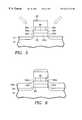
- FIG. 2shows a partially fabricated CIP thin film read head in accordance with a preferred embodiment of the present invention.
- FIG. 3shows a partially fabricated CIP thin film read head in accordance with a preferred embodiment of the present invention.
- FIG. 4shows a partially fabricated CIP thin film read head in accordance with a preferred embodiment of the present invention.
- FIG. 5shows a partially fabricated CIP thin film read head in accordance with a preferred embodiment of the present invention.
- FIG. 6shows a partially fabricated CIP thin film read head in accordance with a preferred embodiment of the present invention.
- FIG. 7shows a partially fabricated CIP thin film read head in accordance with a preferred embodiment of the present invention.
- FIG. 8shows a partially fabricated CIP thin film read head in accordance with a preferred embodiment of the present invention.
- FIG. 9shows a partially fabricated CIP thin film read head in accordance with a preferred embodiment of the present invention.
- FIG. 10shows a partially fabricated CPP thin film read head in accordance with a preferred embodiment of the present invention.
- FIG. 11shows a partially fabricated CPP thin film read head in accordance with a preferred embodiment of the present invention.
- FIG. 12shows a partially fabricated CPP thin film read head in accordance with a preferred embodiment of the present invention.
- the preferred method and structure of the present inventionallows for an improved bias magnet-to-magnetoresistive element interface to improve domain stabilization in magnetoresistive read elements.
- the effects of the improved bias magnet-to-magnetoresistive element interface of the preferred embodiment of the present invention, as noted by the present inventors,is depicted with reference to FIGS. 1A & 1B.
- FIG. 1Aillustrates the magnetic field lines 313 of a conventional bias magnet 213 having a tapered sidewall 213 a opposing magnetoresistive element 220 .
- the conventional bias magnet 213may have a portion 213 a ′overhanging the magnetoresistive element 220 .
- Such structures and configurationcan separately, and in conjunction, cause the magnetic field lines 313 to be distributed through a magnetoresistive element 220 as shown in FIG. 1 A.
- FIG. 1Billustrates the magnetic field lines 315 of a bias magnet 215 with a non-tapered generally planar sidewall 215 a opposing magnetoresistive element 220 .
- the magnetic field lines 315are generally parallel with the plane of the magnetoresistive element 220 , thus increasing the magnitude of the in plane field component near the edge of the magnetoresistive element 220 and improving the stabilizing effect of the bias magnet near the edge of the magnetoresistive element 220 .
- Embodiments of the present inventionmay have a contiguous bias magnet-to-magnetoresistive element junction, such as in CIP devices, or, may have non-contiguous bias magnet-to-magneto-resistive element junction, such as in CPP devices.
- FIGS. 2-9show a cross-sectional view of a partially fabricated CIP embodiment where the plane of the cross-section is parallel to the ABS or air bearing surface.
- a layer 120 of magnetoresistive materialis deposited on a base material 110 .
- the base material 110is an insulator material, which is formed over the wafer.
- insulative base materialis formed on a soft ferromagnetic shield, such as NiFe, which in turn is formed on the wafer substrate.
- the base material 110may be a substrate such as silicon or other type wafer, or it may be an insulation layer formed on, or over, other layers or devices.
- the magnetoresistive material layer 120may have a single layer, or multiple layers, from which a magnetoresistive element will be formed.
- the preferred embodiments of the present inventionhave any known sensor type, such as anisotropic magnetoresistive, spin valve, or any other known type.
- a protective layer 130is deposited on, as shown in FIG. 3, or over, the magnetoresistive layer 120 .
- the protective layer 130is used to protect the underlying surface during formation of permanent magnet and other insulation structures, as will be discussed further below. It is presently preferred to form the protective layer 130 of any typical inorganic insulative material, such as for example Al 2 O 3 , SiO 2 , SiN x , or the like.
- An overhanging or reentrant photoresist structure 40is formed on the protective layer 130 and is used to pattern a magnetoresistive element 20 from magnetoresistive layer 120 .
- the reentrant resist structure 40may be a bilayer resist structure as shown in FIG. 2, or may be fabricated from a single layer, negative resist, trilayer resist, silated, or others as known in the art.
- the magnetoresistive element 20is formed by etching through the protective layer 130 , through the magnetoresistive layer 120 , and into the underlying base material 110 . In some embodiments, it is preferred that the base material not be etched completely through so as to ensure adequate insulative base material to prevent shorting between layers separated by the insulative base material, such as shield and bias magnet material.
- the magnetoresistive element 20may be formed with generally vertical sidewalls 22 a & 22 b .
- Sidewall taperingrather than occurring in the magnetoresistive element sidewalls 22 a & 22 b , instead occurs in the underlying etched base material 10 , shown in FIG. 3 as 10 a & 10 b .
- etching into the underlying base material layerforms the magnetoresistive element with generally planar sidewalls 22 a & 22 b , and, preferred embodiments, forms a cavity in the underlying base material 10 .
- Providing a magnetoresistive element 20 without tapered sidewallsallows for improved bias magnet profile with respect to the magnetoresistive element 20 . It allows the bias magnet to be formed with generally vertical sidewalls 22 a & 22 b opposing the magnetoresistive element sidewalls. This improves the domain structure within the magnetoresistive element 20 , particularly near the edge of the magnetoresistive element 20 .
- a fill layer 115is deposited within the cavity formed in the base material 10 .
- the fill layer 115may be formed of an insulation material, such as for example Al 2 O 3 SiO 2 , SiN x , or the like.
- a portion of the fill layer 115also deposits on the sidewalls 22 a & 22 b of the magnetoresistive 20 and on the sidewalls 32 a & 32 b of protective element 30 .
- a portion of the fill layeralso may form on the top surface 32 c of the protective element 30 under the overhang of bilayer resist structure 40 .
- the amount of the fill layer 115 depositedis dependent upon the amount of base material 110 removed during the formation of the magnetoresistive element 10 .
- Sputtering, physical vapor deposition or PVD, chemical vapor deposition or CVD, or ion beam depositionmay be used to deposit the fill layer 115 .
- the selection of the processwill depend the cavity depth and on the desired ratio of sidewall to vertical deposition. In some embodiments, it is possible to omit the fill layer 115 as discussed below.
- the portion of the fill layer 115 which forms on the sidewalls 22 a & 22 b of the magnetoresistive element 20is removed by directional etching, such as by ion milling, to expose the sidewalls 22 a & 22 b as shown in FIG. 5 .
- a portion of the fill layer 115 which forms on the top surface 32 c of the protective layeralso may be removed during the directional etch process.
- deposition and etching of the fill layer 115should leave a remaining portion 15 of the fill layer approximately level with, or preferably somewhat below, the level of the bottom 22 d of the magnetoresistive element 20 . This allows a bias layer 150 to be deposited so that it abuts the magnetoresistive element 20 , forming a contiguous junction with the sidewalls 22 a & 22 b as shown in FIG. 6 .
- the bias layer 150may be formed of a magnetic material capable of controlling the magnetic orientation and the domain states of the magnetoresistive element 20 . Although any know biasing materials and methods may be used, in the preferred embodiment, a permanent magnet type material, such as CoCrPt, CoPt, CoCr, or other known permanent magnet is used to bias the magnetoresistive element 20 . The use of an underlayer such as Cr and overlayer such as Ta is usually desirable.
- the bias layer 150may deposit with overhanging tapered portions 150 c as shown in FIG. 6 . The overhanging taper portions 150 c may be removed by directional etching of the bias layer 150 as depicted in FIG. 7 .
- the bias layer 50is formed with a generally planar top surface, preferably at about the same level, or slightly above, the top surface 20 c of the magnetoresistive element 20 .
- the protective element 30protects the top 20 c of the magnetoresistive element 20 during removal of the overhanging portions 150 c , as well as during etching of filler layer 50 .
- the bias material 150is etched so that the sidewall etch rate is maximized.
- the etching tilt angle and the rotational angleare adjusted to provide the desired results.
- continuous rotation etchinga combination of static and continuous rotation etching, or etching between a range of rotational angles may be employed to maximize removal of the taper portion 150 c and its overhang.
- a static etch process with tilt angles with respect to wafer normally ranging from 0-70 degrees, a rocking etch process with a rocking angle of 0 degrees static to +/ ⁇ 45 degrees about the axis normal to the wafer plane without substrate rotation, or continuous rotation using conventional substrate rotation with etch angles of 0-70 degrees with respect to wafer normalmay be employed.
- leadsmay be formed on the bias layer 50 prior to resist structure 40 lift-off.
- bias layer 50may electrically couple the leads to the magnetoresistive element 20 .
- resist structure 60is formed on the magnetoresistive element 20 and the lead material extends onto the top surface 20 c of the magnetoresistive element 20 . Because the bias layer 50 does not overhang the magnetoresistive element 20 , the lead material may be deposited on the top surface 20 c closer to sidewalls 20 a & 20 b . In addition, the leads are not pinched off by the overhang of the underlying bias layer 50 . This improves the magnetoresistive element-to-lead interface, improving current density profile and improving definition of the actual effective track width of the device.
- bias layer 50on the insulation layer 10 . This depends upon factors such as the amount of insulation material 10 removed during magnetoresistive element 20 formation and the desired thickness of the bias layer 50 and any underlying structure.
- Additional insulation, shield structures, and a thin film write headtypically are formed over the leads and magnetoresistive element 20 as is known in the art.
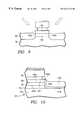
- FIGS. 10-12show a cross-section perpendicular to the ABS of a partially fabricated CPP embodiment.
- the magnetoresistive element 25is formed with a generally planar backwall 25 b distal from an air bearing surface (not shown) by etching into the underlying base layer 15 , as discussed above, to remove backwall taper.
- the base layer 15typically is formed of lead material 15 c , shield material 15 a , or both as shown in FIG. 10, and supplies sensing current across the magnetoresistive element 25 perpendicular to the plane of the layer or layers of the magnetoresistive element 25 .
- Providing a magnetoresistive element 25 without a tapered backwallallows for improved bias magnet profile with respect to the magnetoresistive element 25 . It allows the bias magnet to be formed with generally vertical wall opposing the magnetoresistive element backwall. This improves the domain structure within the magnetoresistive element 25 , particularly near the edge of the magnetoresistive element 25 .
- the protective element 35is used to protect the underlying surface during formation of permanent magnet and other insulation structures, as will be discussed further below. It is presently preferred to form the protective element 35 of any typical inorganic insulative material, such as for example Al 2 O 3 SiO 2 , SiN x , or the like.
- the preferred embodiments of the CPPmay have any known sensor type, such as giant magnetoresistive multilayer, or any other known type.
- the filler layer 116is formed of an insulative material, such as for example Al 2 O 3 SiO 2 , SiN x , or the like, to provide insulation between the base layer 15 and the bias layer 156 .
- the filler layer 116may also serve to insulate the magnetoresistive element 25 from bias material 156 .
- the filler layer 116may be deposited so that it extends along a backwall 25 e of the magnetoresistive element 25 distal from an air bearing surface(not shown). This prevents the bias layer 156 material from creating a shunt path around the magnetoresistive element 25 .
- the amount of the fill layer 116 depositedis dependent upon the amount of base material removed during magnetoresistive element 25 formation, upon the desired separation between bias material 156 and base layer 15 , and upon the desired separation between the bias material 156 and the magnetoresistive element 25 .
- Sputtering, physical vapor deposition or PVD, chemical vapor deposition or CVD, or ion beam depositionmay be used to deposit the fill layer 116 .
- the selection of the processwill depend the cavity depth and on the desired ratio of sidewall to vertical deposition.
- the fill layer 116be formed so that the bias layer 156 forms generally parallel to backwall 25 b , and so that the bias layer 156 extends to about, or to slightly below, the level of the bottom surface 25 d of the magnetoresistive element 25 .
- the fill layer 116on the order of about 1000 Angstroms to 4000 Angstroms of insulative filler material may be deposited using a chemical vapor deposition technique, or a physical sputtering technique such as RF DC magnetron sputttering, so that about 1000 Angstroms of insulation filler material 116 is deposited on the sidewalls 25 a & 25 b of the magnetoresistive element 25 .
- the bias layer 156may be formed of a magnetic material, as discussed above.
- the bias layer 156typically forms with a taper portion 156 c that may overhang the backwall 25 b of the magnetoresistive element 25 . This taper portion 156 c and its overhang can affect the direction and stability of the induced longitudinal field within the magnetoresistive element as discussed above.
- the bias layer 156is etched to remove the taper portion 156 c and its overhang, as shown in FIG. 11 .
- directional etchingis used to remove the overhanging portion and substantially all the remaining portion of the taper 156 c .
- an excess of bias materialis deposited so that after etching to remove the taper 156 c , the top surface 56 c of the bias layer 56 extends slightly above, or is at the same level of the top surface 25 c of the magnetoresistive element 25 .
- the bias material 156is etched so that the sidewall etch rate is maximized.
- the etching tilt angle and the rotational angleare adjusted to provide the desired results.
- continuous rotation etchinga combination of static and continuous rotation etching, or etching between a range of rotational angles may be employed to maximize removal of the taper portion 156 c and its overhang.
- a static etch process with tilt angles with respect to wafer normally ranging from 0-70 degrees, a rocking etch process with a rocking angle of 0 degrees static to +/ ⁇ 45 degrees about the axis normal to the wafer plane without substrate rotation, or continuous rotation using conventional substrate rotation with etch angles of 0-70 degrees with respect to wafer normalmay be employed.
- an additional insulation layer 176may be deposited over on the etched bias layer 56 , and the resist structure 45 removed, to allow for vias (not shown) to be formed through the protective element 35 for couple sensing current through the magnetoresistive CPP device. Or, as discussed above, the protective insulation element 35 may be removed prior to forming a lead to the sensor element. Additional insulation, shield structures, and a thin film write head may be formed over the leads and magnetoresistive element 20 as is known in the art.
Landscapes
- Engineering & Computer Science (AREA)
- Chemical & Material Sciences (AREA)
- Nanotechnology (AREA)
- Manufacturing & Machinery (AREA)
- Physics & Mathematics (AREA)
- Mathematical Physics (AREA)
- Theoretical Computer Science (AREA)
- Crystallography & Structural Chemistry (AREA)
- Magnetic Heads (AREA)
- Hall/Mr Elements (AREA)
Abstract
Description
Claims (7)
Priority Applications (3)
| Application Number | Priority Date | Filing Date | Title |
|---|---|---|---|
| US09/400,205US6421212B1 (en) | 1999-09-21 | 1999-09-21 | Thin film read head structure with improved bias magnet-to-magnetoresistive element interface and method of fabrication |
| US10/152,909US6735850B1 (en) | 1999-09-21 | 2002-05-20 | Thin film read head structure with improved bias magnet-to-magnetoresistive element interface and method of fabrication |
| US10/153,067US6487056B1 (en) | 1999-09-21 | 2002-05-20 | Thin film read head structure with improved bias magnet-to-magnetoresistive element interface and method of fabrication |
Applications Claiming Priority (1)
| Application Number | Priority Date | Filing Date | Title |
|---|---|---|---|
| US09/400,205US6421212B1 (en) | 1999-09-21 | 1999-09-21 | Thin film read head structure with improved bias magnet-to-magnetoresistive element interface and method of fabrication |
Related Child Applications (2)
| Application Number | Title | Priority Date | Filing Date |
|---|---|---|---|
| US10/153,067ContinuationUS6487056B1 (en) | 1999-09-21 | 2002-05-20 | Thin film read head structure with improved bias magnet-to-magnetoresistive element interface and method of fabrication |
| US10/152,909DivisionUS6735850B1 (en) | 1999-09-21 | 2002-05-20 | Thin film read head structure with improved bias magnet-to-magnetoresistive element interface and method of fabrication |
Publications (1)
| Publication Number | Publication Date |
|---|---|
| US6421212B1true US6421212B1 (en) | 2002-07-16 |
Family
ID=23582651
Family Applications (3)
| Application Number | Title | Priority Date | Filing Date |
|---|---|---|---|
| US09/400,205Expired - LifetimeUS6421212B1 (en) | 1999-09-21 | 1999-09-21 | Thin film read head structure with improved bias magnet-to-magnetoresistive element interface and method of fabrication |
| US10/152,909Expired - LifetimeUS6735850B1 (en) | 1999-09-21 | 2002-05-20 | Thin film read head structure with improved bias magnet-to-magnetoresistive element interface and method of fabrication |
| US10/153,067Expired - LifetimeUS6487056B1 (en) | 1999-09-21 | 2002-05-20 | Thin film read head structure with improved bias magnet-to-magnetoresistive element interface and method of fabrication |
Family Applications After (2)
| Application Number | Title | Priority Date | Filing Date |
|---|---|---|---|
| US10/152,909Expired - LifetimeUS6735850B1 (en) | 1999-09-21 | 2002-05-20 | Thin film read head structure with improved bias magnet-to-magnetoresistive element interface and method of fabrication |
| US10/153,067Expired - LifetimeUS6487056B1 (en) | 1999-09-21 | 2002-05-20 | Thin film read head structure with improved bias magnet-to-magnetoresistive element interface and method of fabrication |
Country Status (1)
| Country | Link |
|---|---|
| US (3) | US6421212B1 (en) |
Cited By (150)
| Publication number | Priority date | Publication date | Assignee | Title |
|---|---|---|---|---|
| US20010014001A1 (en)* | 1999-12-07 | 2001-08-16 | Fujitsu Limited | Magnetoresistance effect magnetic head and magnetic effect reproducing apparatus |
| US6487056B1 (en)* | 1999-09-21 | 2002-11-26 | Read-Rite Corporation | Thin film read head structure with improved bias magnet-to-magnetoresistive element interface and method of fabrication |
| US20040169958A1 (en)* | 2003-02-27 | 2004-09-02 | Krounbi Mohamad T. | Thin film recording head with a buried coil providing a shortened yoke and improved dimension control |
| US20040179312A1 (en)* | 2003-03-13 | 2004-09-16 | Freitag James Mac | Low resistance antiparallel tab magnetoresistive sensor |
| US20040214353A1 (en)* | 2003-04-23 | 2004-10-28 | Alps Electric Co., Ltd. | Manufacturing method of CPP type magnetic sensor having current-squeezing path |
| US6821451B2 (en)* | 2000-03-28 | 2004-11-23 | Tdk Corporation | Dry etching method, microfabrication process and dry etching mask |
| US20040257716A1 (en)* | 2003-06-17 | 2004-12-23 | Heim David Eugene | Magnetoresistive sensor having bias magnets with steep endwalls |
| US20050068697A1 (en)* | 2003-09-30 | 2005-03-31 | Pinarbasi Mustafa Michael | Magnetoresistive sensor for magnetic head having minimized spacing between hard bias elements and free magnetic layer |
| US20050128651A1 (en)* | 2003-12-16 | 2005-06-16 | Seagate Technology Llc | Spin polarization enhancement artificial magnet |
| US20050231856A1 (en)* | 2004-04-20 | 2005-10-20 | Headway Technologies, Inc. | Xenon ion beam to improve track width definition |
| WO2005101375A1 (en)* | 2004-04-02 | 2005-10-27 | Tdk Corporation | Stabilizer for magnetoresistive head and method of manufacture |
| US20060000078A1 (en)* | 2004-06-30 | 2006-01-05 | Pinarbasi Mustafa M | Methods of making a CPP read sensor with use of a resist without undercuts and high angle ion milling |
| US20060012923A1 (en)* | 2004-07-15 | 2006-01-19 | Hitachi Global Storage Technologies Netherlands B.V. | Thin film magnetic head and fabrication process |
| US20070133133A1 (en)* | 2005-12-14 | 2007-06-14 | Hitachi Global Storage Technologies | Current perpendicular to plane magnetoresistive sensor having a shape enhanced pinned layer and an in stack bias structure |
| US20070289122A1 (en)* | 2006-06-16 | 2007-12-20 | Tdk Corporation | Manufacturing method of magnetoresistive effect element, manufacturing method of thin-film magnetic head and thin-film magnetic head |
| US20080137237A1 (en)* | 2006-12-12 | 2008-06-12 | Hitachi Global Storage Technologies | Magnetoresistive sensor having a hard bias buffer layer, seed layer structure providing exceptionally high magnetic orientation ratio |
| US20090244789A1 (en)* | 2008-04-01 | 2009-10-01 | Westem Digital (Fremont), Llc | Method and system for providing a hard bias capping layer |
| US8349195B1 (en) | 2008-06-27 | 2013-01-08 | Western Digital (Fremont), Llc | Method and system for providing a magnetoresistive structure using undercut free mask |
| US8611054B1 (en) | 2012-04-11 | 2013-12-17 | Western Digital (Fremont), Llc | Antiferromagnetically-coupled soft bias magnetoresistive read head, and fabrication method therefore |
| US8830628B1 (en) | 2009-02-23 | 2014-09-09 | Western Digital (Fremont), Llc | Method and system for providing a perpendicular magnetic recording head |
| US8879207B1 (en) | 2011-12-20 | 2014-11-04 | Western Digital (Fremont), Llc | Method for providing a side shield for a magnetic recording transducer using an air bridge |
| US8883017B1 (en) | 2013-03-12 | 2014-11-11 | Western Digital (Fremont), Llc | Method and system for providing a read transducer having seamless interfaces |
| US8917581B1 (en) | 2013-12-18 | 2014-12-23 | Western Digital Technologies, Inc. | Self-anneal process for a near field transducer and chimney in a hard disk drive assembly |
| US8923102B1 (en) | 2013-07-16 | 2014-12-30 | Western Digital (Fremont), Llc | Optical grating coupling for interferometric waveguides in heat assisted magnetic recording heads |
| US8947985B1 (en) | 2013-07-16 | 2015-02-03 | Western Digital (Fremont), Llc | Heat assisted magnetic recording transducers having a recessed pole |
| US8953422B1 (en) | 2014-06-10 | 2015-02-10 | Western Digital (Fremont), Llc | Near field transducer using dielectric waveguide core with fine ridge feature |
| US8958272B1 (en) | 2014-06-10 | 2015-02-17 | Western Digital (Fremont), Llc | Interfering near field transducer for energy assisted magnetic recording |
| US8971160B1 (en) | 2013-12-19 | 2015-03-03 | Western Digital (Fremont), Llc | Near field transducer with high refractive index pin for heat assisted magnetic recording |
| US8970988B1 (en) | 2013-12-31 | 2015-03-03 | Western Digital (Fremont), Llc | Electric gaps and method for making electric gaps for multiple sensor arrays |
| US8976635B1 (en) | 2014-06-10 | 2015-03-10 | Western Digital (Fremont), Llc | Near field transducer driven by a transverse electric waveguide for energy assisted magnetic recording |
| US8982508B1 (en) | 2011-10-31 | 2015-03-17 | Western Digital (Fremont), Llc | Method for providing a side shield for a magnetic recording transducer |
| US8980109B1 (en) | 2012-12-11 | 2015-03-17 | Western Digital (Fremont), Llc | Method for providing a magnetic recording transducer using a combined main pole and side shield CMP for a wraparound shield scheme |
| US8988812B1 (en) | 2013-11-27 | 2015-03-24 | Western Digital (Fremont), Llc | Multi-sensor array configuration for a two-dimensional magnetic recording (TDMR) operation |
| US8984740B1 (en) | 2012-11-30 | 2015-03-24 | Western Digital (Fremont), Llc | Process for providing a magnetic recording transducer having a smooth magnetic seed layer |
| US8988825B1 (en) | 2014-02-28 | 2015-03-24 | Western Digital (Fremont, LLC | Method for fabricating a magnetic writer having half-side shields |
| US8993217B1 (en) | 2013-04-04 | 2015-03-31 | Western Digital (Fremont), Llc | Double exposure technique for high resolution disk imaging |
| US8995087B1 (en) | 2006-11-29 | 2015-03-31 | Western Digital (Fremont), Llc | Perpendicular magnetic recording write head having a wrap around shield |
| US8997832B1 (en) | 2010-11-23 | 2015-04-07 | Western Digital (Fremont), Llc | Method of fabricating micrometer scale components |
| US9001467B1 (en) | 2014-03-05 | 2015-04-07 | Western Digital (Fremont), Llc | Method for fabricating side shields in a magnetic writer |
| US9001628B1 (en) | 2013-12-16 | 2015-04-07 | Western Digital (Fremont), Llc | Assistant waveguides for evaluating main waveguide coupling efficiency and diode laser alignment tolerances for hard disk |
| US9007719B1 (en) | 2013-10-23 | 2015-04-14 | Western Digital (Fremont), Llc | Systems and methods for using double mask techniques to achieve very small features |
| US9007725B1 (en) | 2014-10-07 | 2015-04-14 | Western Digital (Fremont), Llc | Sensor with positive coupling between dual ferromagnetic free layer laminates |
| US9007879B1 (en) | 2014-06-10 | 2015-04-14 | Western Digital (Fremont), Llc | Interfering near field transducer having a wide metal bar feature for energy assisted magnetic recording |
| US9013836B1 (en) | 2013-04-02 | 2015-04-21 | Western Digital (Fremont), Llc | Method and system for providing an antiferromagnetically coupled return pole |
| US9042051B2 (en) | 2013-08-15 | 2015-05-26 | Western Digital (Fremont), Llc | Gradient write gap for perpendicular magnetic recording writer |
| US9042058B1 (en) | 2013-10-17 | 2015-05-26 | Western Digital Technologies, Inc. | Shield designed for middle shields in a multiple sensor array |
| US9042052B1 (en) | 2014-06-23 | 2015-05-26 | Western Digital (Fremont), Llc | Magnetic writer having a partially shunted coil |
| US9042208B1 (en) | 2013-03-11 | 2015-05-26 | Western Digital Technologies, Inc. | Disk drive measuring fly height by applying a bias voltage to an electrically insulated write component of a head |
| US9042057B1 (en) | 2013-01-09 | 2015-05-26 | Western Digital (Fremont), Llc | Methods for providing magnetic storage elements with high magneto-resistance using Heusler alloys |
| US9053735B1 (en) | 2014-06-20 | 2015-06-09 | Western Digital (Fremont), Llc | Method for fabricating a magnetic writer using a full-film metal planarization |
| US9065043B1 (en) | 2012-06-29 | 2015-06-23 | Western Digital (Fremont), Llc | Tunnel magnetoresistance read head with narrow shield-to-shield spacing |
| US9064528B1 (en) | 2013-05-17 | 2015-06-23 | Western Digital Technologies, Inc. | Interferometric waveguide usable in shingled heat assisted magnetic recording in the absence of a near-field transducer |
| US9064507B1 (en) | 2009-07-31 | 2015-06-23 | Western Digital (Fremont), Llc | Magnetic etch-stop layer for magnetoresistive read heads |
| US9064527B1 (en) | 2013-04-12 | 2015-06-23 | Western Digital (Fremont), Llc | High order tapered waveguide for use in a heat assisted magnetic recording head |
| US9070381B1 (en) | 2013-04-12 | 2015-06-30 | Western Digital (Fremont), Llc | Magnetic recording read transducer having a laminated free layer |
| US9082423B1 (en) | 2013-12-18 | 2015-07-14 | Western Digital (Fremont), Llc | Magnetic recording write transducer having an improved trailing surface profile |
| US9087534B1 (en) | 2011-12-20 | 2015-07-21 | Western Digital (Fremont), Llc | Method and system for providing a read transducer having soft and hard magnetic bias structures |
| US9087527B1 (en) | 2014-10-28 | 2015-07-21 | Western Digital (Fremont), Llc | Apparatus and method for middle shield connection in magnetic recording transducers |
| US9093639B2 (en) | 2012-02-21 | 2015-07-28 | Western Digital (Fremont), Llc | Methods for manufacturing a magnetoresistive structure utilizing heating and cooling |
| US9104107B1 (en) | 2013-04-03 | 2015-08-11 | Western Digital (Fremont), Llc | DUV photoresist process |
| US9111564B1 (en) | 2013-04-02 | 2015-08-18 | Western Digital (Fremont), Llc | Magnetic recording writer having a main pole with multiple flare angles |
| US9111550B1 (en) | 2014-12-04 | 2015-08-18 | Western Digital (Fremont), Llc | Write transducer having a magnetic buffer layer spaced between a side shield and a write pole by non-magnetic layers |
| US9111558B1 (en) | 2014-03-14 | 2015-08-18 | Western Digital (Fremont), Llc | System and method of diffractive focusing of light in a waveguide |
| US9123359B1 (en) | 2010-12-22 | 2015-09-01 | Western Digital (Fremont), Llc | Magnetic recording transducer with sputtered antiferromagnetic coupling trilayer between plated ferromagnetic shields and method of fabrication |
| US9123358B1 (en) | 2012-06-11 | 2015-09-01 | Western Digital (Fremont), Llc | Conformal high moment side shield seed layer for perpendicular magnetic recording writer |
| US9123362B1 (en) | 2011-03-22 | 2015-09-01 | Western Digital (Fremont), Llc | Methods for assembling an electrically assisted magnetic recording (EAMR) head |
| US9123374B1 (en) | 2015-02-12 | 2015-09-01 | Western Digital (Fremont), Llc | Heat assisted magnetic recording writer having an integrated polarization rotation plate |
| US9135937B1 (en) | 2014-05-09 | 2015-09-15 | Western Digital (Fremont), Llc | Current modulation on laser diode for energy assisted magnetic recording transducer |
| US9135930B1 (en) | 2014-03-06 | 2015-09-15 | Western Digital (Fremont), Llc | Method for fabricating a magnetic write pole using vacuum deposition |
| US9142233B1 (en) | 2014-02-28 | 2015-09-22 | Western Digital (Fremont), Llc | Heat assisted magnetic recording writer having a recessed pole |
| US9147404B1 (en) | 2015-03-31 | 2015-09-29 | Western Digital (Fremont), Llc | Method and system for providing a read transducer having a dual free layer |
| US9147408B1 (en) | 2013-12-19 | 2015-09-29 | Western Digital (Fremont), Llc | Heated AFM layer deposition and cooling process for TMR magnetic recording sensor with high pinning field |
| US9153255B1 (en) | 2014-03-05 | 2015-10-06 | Western Digital (Fremont), Llc | Method for fabricating a magnetic writer having an asymmetric gap and shields |
| US9183854B2 (en) | 2014-02-24 | 2015-11-10 | Western Digital (Fremont), Llc | Method to make interferometric taper waveguide for HAMR light delivery |
| US9190079B1 (en) | 2014-09-22 | 2015-11-17 | Western Digital (Fremont), Llc | Magnetic write pole having engineered radius of curvature and chisel angle profiles |
| US9190085B1 (en) | 2014-03-12 | 2015-11-17 | Western Digital (Fremont), Llc | Waveguide with reflective grating for localized energy intensity |
| US9196270B1 (en)* | 2006-12-07 | 2015-11-24 | Western Digital (Fremont), Llc | Method for providing a magnetoresistive element having small critical dimensions |
| US9194692B1 (en) | 2013-12-06 | 2015-11-24 | Western Digital (Fremont), Llc | Systems and methods for using white light interferometry to measure undercut of a bi-layer structure |
| US9202480B2 (en) | 2009-10-14 | 2015-12-01 | Western Digital (Fremont), LLC. | Double patterning hard mask for damascene perpendicular magnetic recording (PMR) writer |
| US9202493B1 (en) | 2014-02-28 | 2015-12-01 | Western Digital (Fremont), Llc | Method of making an ultra-sharp tip mode converter for a HAMR head |
| US9214172B2 (en) | 2013-10-23 | 2015-12-15 | Western Digital (Fremont), Llc | Method of manufacturing a magnetic read head |
| US9214165B1 (en) | 2014-12-18 | 2015-12-15 | Western Digital (Fremont), Llc | Magnetic writer having a gradient in saturation magnetization of the shields |
| US9214169B1 (en) | 2014-06-20 | 2015-12-15 | Western Digital (Fremont), Llc | Magnetic recording read transducer having a laminated free layer |
| US9213322B1 (en) | 2012-08-16 | 2015-12-15 | Western Digital (Fremont), Llc | Methods for providing run to run process control using a dynamic tuner |
| US9230565B1 (en) | 2014-06-24 | 2016-01-05 | Western Digital (Fremont), Llc | Magnetic shield for magnetic recording head |
| US9236560B1 (en) | 2014-12-08 | 2016-01-12 | Western Digital (Fremont), Llc | Spin transfer torque tunneling magnetoresistive device having a laminated free layer with perpendicular magnetic anisotropy |
| US9245543B1 (en) | 2010-06-25 | 2016-01-26 | Western Digital (Fremont), Llc | Method for providing an energy assisted magnetic recording head having a laser integrally mounted to the slider |
| US9245562B1 (en) | 2015-03-30 | 2016-01-26 | Western Digital (Fremont), Llc | Magnetic recording writer with a composite main pole |
| US9245545B1 (en) | 2013-04-12 | 2016-01-26 | Wester Digital (Fremont), Llc | Short yoke length coils for magnetic heads in disk drives |
| US9251813B1 (en) | 2009-04-19 | 2016-02-02 | Western Digital (Fremont), Llc | Method of making a magnetic recording head |
| US9263071B1 (en) | 2015-03-31 | 2016-02-16 | Western Digital (Fremont), Llc | Flat NFT for heat assisted magnetic recording |
| US9263067B1 (en) | 2013-05-29 | 2016-02-16 | Western Digital (Fremont), Llc | Process for making PMR writer with constant side wall angle |
| US9269382B1 (en) | 2012-06-29 | 2016-02-23 | Western Digital (Fremont), Llc | Method and system for providing a read transducer having improved pinning of the pinned layer at higher recording densities |
| US9275657B1 (en) | 2013-08-14 | 2016-03-01 | Western Digital (Fremont), Llc | Process for making PMR writer with non-conformal side gaps |
| US9280990B1 (en) | 2013-12-11 | 2016-03-08 | Western Digital (Fremont), Llc | Method for fabricating a magnetic writer using multiple etches |
| US9286919B1 (en) | 2014-12-17 | 2016-03-15 | Western Digital (Fremont), Llc | Magnetic writer having a dual side gap |
| US9287494B1 (en) | 2013-06-28 | 2016-03-15 | Western Digital (Fremont), Llc | Magnetic tunnel junction (MTJ) with a magnesium oxide tunnel barrier |
| US9305583B1 (en) | 2014-02-18 | 2016-04-05 | Western Digital (Fremont), Llc | Method for fabricating a magnetic writer using multiple etches of damascene materials |
| US9312064B1 (en) | 2015-03-02 | 2016-04-12 | Western Digital (Fremont), Llc | Method to fabricate a magnetic head including ion milling of read gap using dual layer hard mask |
| US9318130B1 (en) | 2013-07-02 | 2016-04-19 | Western Digital (Fremont), Llc | Method to fabricate tunneling magnetic recording heads with extended pinned layer |
| US9336814B1 (en) | 2013-03-12 | 2016-05-10 | Western Digital (Fremont), Llc | Inverse tapered waveguide for use in a heat assisted magnetic recording head |
| US9343098B1 (en) | 2013-08-23 | 2016-05-17 | Western Digital (Fremont), Llc | Method for providing a heat assisted magnetic recording transducer having protective pads |
| US9343087B1 (en) | 2014-12-21 | 2016-05-17 | Western Digital (Fremont), Llc | Method for fabricating a magnetic writer having half shields |
| US9343086B1 (en) | 2013-09-11 | 2016-05-17 | Western Digital (Fremont), Llc | Magnetic recording write transducer having an improved sidewall angle profile |
| US9349394B1 (en) | 2013-10-18 | 2016-05-24 | Western Digital (Fremont), Llc | Method for fabricating a magnetic writer having a gradient side gap |
| US9349392B1 (en) | 2012-05-24 | 2016-05-24 | Western Digital (Fremont), Llc | Methods for improving adhesion on dielectric substrates |
| US9361913B1 (en) | 2013-06-03 | 2016-06-07 | Western Digital (Fremont), Llc | Recording read heads with a multi-layer AFM layer methods and apparatuses |
| US9361914B1 (en) | 2014-06-18 | 2016-06-07 | Western Digital (Fremont), Llc | Magnetic sensor with thin capping layer |
| US9368134B1 (en) | 2010-12-16 | 2016-06-14 | Western Digital (Fremont), Llc | Method and system for providing an antiferromagnetically coupled writer |
| US9384765B1 (en) | 2015-09-24 | 2016-07-05 | Western Digital (Fremont), Llc | Method and system for providing a HAMR writer having improved optical efficiency |
| US9384763B1 (en) | 2015-03-26 | 2016-07-05 | Western Digital (Fremont), Llc | Dual free layer magnetic reader having a rear bias structure including a soft bias layer |
| US9396742B1 (en) | 2012-11-30 | 2016-07-19 | Western Digital (Fremont), Llc | Magnetoresistive sensor for a magnetic storage system read head, and fabrication method thereof |
| US9396743B1 (en) | 2014-02-28 | 2016-07-19 | Western Digital (Fremont), Llc | Systems and methods for controlling soft bias thickness for tunnel magnetoresistance readers |
| US9406331B1 (en) | 2013-06-17 | 2016-08-02 | Western Digital (Fremont), Llc | Method for making ultra-narrow read sensor and read transducer device resulting therefrom |
| US9424866B1 (en) | 2015-09-24 | 2016-08-23 | Western Digital (Fremont), Llc | Heat assisted magnetic recording write apparatus having a dielectric gap |
| US9431039B1 (en) | 2013-05-21 | 2016-08-30 | Western Digital (Fremont), Llc | Multiple sensor array usable in two-dimensional magnetic recording |
| US9431031B1 (en) | 2015-03-24 | 2016-08-30 | Western Digital (Fremont), Llc | System and method for magnetic transducers having multiple sensors and AFC shields |
| US9431038B1 (en) | 2015-06-29 | 2016-08-30 | Western Digital (Fremont), Llc | Method for fabricating a magnetic write pole having an improved sidewall angle profile |
| US9431047B1 (en) | 2013-05-01 | 2016-08-30 | Western Digital (Fremont), Llc | Method for providing an improved AFM reader shield |
| US9431032B1 (en) | 2013-08-14 | 2016-08-30 | Western Digital (Fremont), Llc | Electrical connection arrangement for a multiple sensor array usable in two-dimensional magnetic recording |
| US9437251B1 (en) | 2014-12-22 | 2016-09-06 | Western Digital (Fremont), Llc | Apparatus and method having TDMR reader to reader shunts |
| US9443541B1 (en) | 2015-03-24 | 2016-09-13 | Western Digital (Fremont), Llc | Magnetic writer having a gradient in saturation magnetization of the shields and return pole |
| US9441938B1 (en) | 2013-10-08 | 2016-09-13 | Western Digital (Fremont), Llc | Test structures for measuring near field transducer disc length |
| US9449625B1 (en) | 2014-12-24 | 2016-09-20 | Western Digital (Fremont), Llc | Heat assisted magnetic recording head having a plurality of diffusion barrier layers |
| US9449621B1 (en) | 2015-03-26 | 2016-09-20 | Western Digital (Fremont), Llc | Dual free layer magnetic reader having a rear bias structure having a high aspect ratio |
| US9472216B1 (en) | 2015-09-23 | 2016-10-18 | Western Digital (Fremont), Llc | Differential dual free layer magnetic reader |
| US9484051B1 (en) | 2015-11-09 | 2016-11-01 | The Provost, Fellows, Foundation Scholars and the other members of Board, of the College of the Holy and Undivided Trinity of Queen Elizabeth near Dublin | Method and system for reducing undesirable reflections in a HAMR write apparatus |
| US9508365B1 (en) | 2015-06-24 | 2016-11-29 | Western Digital (Fremont), LLC. | Magnetic reader having a crystal decoupling structure |
| US9508372B1 (en) | 2015-06-03 | 2016-11-29 | Western Digital (Fremont), Llc | Shingle magnetic writer having a low sidewall angle pole |
| US9508363B1 (en) | 2014-06-17 | 2016-11-29 | Western Digital (Fremont), Llc | Method for fabricating a magnetic write pole having a leading edge bevel |
| US9530443B1 (en) | 2015-06-25 | 2016-12-27 | Western Digital (Fremont), Llc | Method for fabricating a magnetic recording device having a high aspect ratio structure |
| US9564150B1 (en) | 2015-11-24 | 2017-02-07 | Western Digital (Fremont), Llc | Magnetic read apparatus having an improved read sensor isolation circuit |
| US9595273B1 (en) | 2015-09-30 | 2017-03-14 | Western Digital (Fremont), Llc | Shingle magnetic writer having nonconformal shields |
| US9646639B2 (en) | 2015-06-26 | 2017-05-09 | Western Digital (Fremont), Llc | Heat assisted magnetic recording writer having integrated polarization rotation waveguides |
| US9666214B1 (en) | 2015-09-23 | 2017-05-30 | Western Digital (Fremont), Llc | Free layer magnetic reader that may have a reduced shield-to-shield spacing |
| US9721595B1 (en) | 2014-12-04 | 2017-08-01 | Western Digital (Fremont), Llc | Method for providing a storage device |
| US9741366B1 (en) | 2014-12-18 | 2017-08-22 | Western Digital (Fremont), Llc | Method for fabricating a magnetic writer having a gradient in saturation magnetization of the shields |
| US9740805B1 (en) | 2015-12-01 | 2017-08-22 | Western Digital (Fremont), Llc | Method and system for detecting hotspots for photolithographically-defined devices |
| US9754611B1 (en) | 2015-11-30 | 2017-09-05 | Western Digital (Fremont), Llc | Magnetic recording write apparatus having a stepped conformal trailing shield |
| US9767831B1 (en) | 2015-12-01 | 2017-09-19 | Western Digital (Fremont), Llc | Magnetic writer having convex trailing surface pole and conformal write gap |
| US9786301B1 (en) | 2014-12-02 | 2017-10-10 | Western Digital (Fremont), Llc | Apparatuses and methods for providing thin shields in a multiple sensor array |
| US9799351B1 (en) | 2015-11-30 | 2017-10-24 | Western Digital (Fremont), Llc | Short yoke length writer having assist coils |
| US9812155B1 (en) | 2015-11-23 | 2017-11-07 | Western Digital (Fremont), Llc | Method and system for fabricating high junction angle read sensors |
| US9842615B1 (en) | 2015-06-26 | 2017-12-12 | Western Digital (Fremont), Llc | Magnetic reader having a nonmagnetic insertion layer for the pinning layer |
| US9858951B1 (en) | 2015-12-01 | 2018-01-02 | Western Digital (Fremont), Llc | Method for providing a multilayer AFM layer in a read sensor |
| US9881638B1 (en) | 2014-12-17 | 2018-01-30 | Western Digital (Fremont), Llc | Method for providing a near-field transducer (NFT) for a heat assisted magnetic recording (HAMR) device |
| US9934811B1 (en) | 2014-03-07 | 2018-04-03 | Western Digital (Fremont), Llc | Methods for controlling stray fields of magnetic features using magneto-elastic anisotropy |
| US9953670B1 (en) | 2015-11-10 | 2018-04-24 | Western Digital (Fremont), Llc | Method and system for providing a HAMR writer including a multi-mode interference device |
| US10037770B1 (en) | 2015-11-12 | 2018-07-31 | Western Digital (Fremont), Llc | Method for providing a magnetic recording write apparatus having a seamless pole |
| US10074387B1 (en) | 2014-12-21 | 2018-09-11 | Western Digital (Fremont), Llc | Method and system for providing a read transducer having symmetric antiferromagnetically coupled shields |
Families Citing this family (20)
| Publication number | Priority date | Publication date | Assignee | Title |
|---|---|---|---|---|
| JP2002050011A (en) | 2000-08-03 | 2002-02-15 | Nec Corp | Magnetoresistive effect element, magnetoresistive effect head, magnetoresistive conversion system, and magnetic recording system |
| US20020131215A1 (en)* | 2001-03-14 | 2002-09-19 | Beach Robert S. | Tunnel junction and charge perpendicular-to-plane magnetic recording sensors and method of manufacture |
| US20020171962A1 (en)* | 2001-05-15 | 2002-11-21 | Seagate Technology Llc | Semiconductor/metal read sensor for magnetic recording |
| US7367110B2 (en)* | 2004-09-27 | 2008-05-06 | Hitachi Global Storage Technologies Netherlands B.V. | Method of fabricating a read head having shaped read sensor-biasing layer junctions using partial milling |
| US9098118B2 (en)* | 2004-10-20 | 2015-08-04 | Robert R. Kodama | Computer keyboard with pointer control |
| US7333304B2 (en)* | 2004-11-04 | 2008-02-19 | Hitachi Global Storage Technologies Netherlands B.V. | CPP sensor having hard bias stabilization placed at back edge of the stripe |
| US7593186B2 (en)* | 2005-01-31 | 2009-09-22 | Hitachi Global Storage Technologies Netherlands B.V. | P1 write pole with shoulder formation |
| US7360299B2 (en)* | 2005-03-31 | 2008-04-22 | Hitachi Global Storage Technologies Netherlands B. V. | Method for manufacturing a magnetic read sensor employing oblique etched underlayers for inducing uniaxial magnetic anisotropy in a hard magnetic in-stack bias layer |
| US7363699B2 (en)* | 2005-03-31 | 2008-04-29 | Hitachi Global Storage Technologies Netherlands B. V. | Method for manufacturing a magnetic read sensor employing oblique etched underlayers for inducing uniaxial magnetic anisotropy in hard magnetic bias layers |
| US7457085B2 (en) | 2005-03-31 | 2008-11-25 | Hitachi Global Storage Technologies Netherlands B.V. | Magnetic read sensor employing oblique etched underlayers for inducing uniaxial magnetic anisotropy in hard magnetic bias layers |
| US7382586B2 (en)* | 2005-03-31 | 2008-06-03 | Hitachi Global Storage Technologies Netherlands B.V. | Magnetic read sensor employing oblique etched underlayers for inducing uniaxial magnetic anisotropy in a self biased free layer |
| US7460343B2 (en)* | 2005-03-31 | 2008-12-02 | Hitachi Global Storage Technologies Netherlands B.V. | Magnetic read sensor employing oblique etched underlayers for inducing uniaxial magnetic anisotropy in a hard magnetic in-stack bias layer |
| US7360300B2 (en) | 2005-03-31 | 2008-04-22 | Hitachi Global Storage Technologies Netherlands B.V. | Method for manufacturing a magnetic read sensor employing oblique etched underlayers for inducing uniaxial magnetic anisotropy in a hard magnetic pinning layer |
| US7672090B2 (en)* | 2005-03-31 | 2010-03-02 | Hitachi Global Storage Technologies Netherlands B.V. | Magnetic read sensor employing oblique etched underlayers for inducing uniaxial magnetic anisotropy in a hard magnetic pinning layer |
| US7562436B2 (en)* | 2005-07-29 | 2009-07-21 | Hitachi Global Storage Technologies Netherlands B.V. | Deposition defined trackwidth for very narrow trackwidth CPP device |
| US20080003245A1 (en)* | 2006-06-30 | 2008-01-03 | Beiersdorf Ag | Use of octyl salicylate in cosmetic preparations containing 1,3-dihydroxyacetone |
| US7652855B2 (en)* | 2006-11-09 | 2010-01-26 | Hitachi Global Storage Technologies Netherlands B.V. | Magnetic sensor with extended free layer and overlaid leads |
| US8066897B2 (en)* | 2007-12-28 | 2011-11-29 | Hitachi Global Storage Technologies Netherlands B.V. | Dynamic hard magnet thickness adjustment for reduced variation in free layer stabilization field in a magnetoresistive sensor |
| JP2009301661A (en)* | 2008-06-13 | 2009-12-24 | Fujitsu Ltd | Method of manufacturing reproducing head |
| US20110007426A1 (en)* | 2009-07-13 | 2011-01-13 | Seagate Technology Llc | Trapezoidal back bias and trilayer reader geometry to enhance device performance |
Citations (14)
| Publication number | Priority date | Publication date | Assignee | Title |
|---|---|---|---|---|
| JPH07210832A (en)* | 1993-12-23 | 1995-08-11 | Internatl Business Mach Corp <Ibm> | Multilayer magnetoresistance sensor |
| US5640343A (en) | 1996-03-18 | 1997-06-17 | International Business Machines Corporation | Magnetic memory array using magnetic tunnel junction devices in the memory cells |
| US5712612A (en)* | 1996-01-02 | 1998-01-27 | Hewlett-Packard Company | Tunneling ferrimagnetic magnetoresistive sensor |
| US5729410A (en)* | 1996-11-27 | 1998-03-17 | International Business Machines Corporation | Magnetic tunnel junction device with longitudinal biasing |
| US5792510A (en) | 1997-06-10 | 1998-08-11 | International Business Machines Corporation | Method for making a chemically-ordered magnetic metal alloy film |
| US5828531A (en)* | 1996-09-18 | 1998-10-27 | International Business Machines Corporation | Spin valve sensor with enhanced magnetoresistance |
| US5898547A (en)* | 1997-10-24 | 1999-04-27 | International Business Machines Corporation | Magnetic tunnel junction magnetoresistive read head with sensing layer as flux guide |
| US5898548A (en)* | 1997-10-24 | 1999-04-27 | International Business Machines Corporation | Shielded magnetic tunnel junction magnetoresistive read head |
| US5901018A (en)* | 1997-10-24 | 1999-05-04 | International Business Machines Corporation | Magnetic tunnel junction magnetoresistive read head with sensing layer as rear flux guide |
| US5966012A (en)* | 1997-10-07 | 1999-10-12 | International Business Machines Corporation | Magnetic tunnel junction device with improved fixed and free ferromagnetic layers |
| US6005753A (en)* | 1998-05-29 | 1999-12-21 | International Business Machines Corporation | Magnetic tunnel junction magnetoresistive read head with longitudinal and transverse bias |
| US6061211A (en)* | 1994-03-17 | 2000-05-09 | Kabushiki Kaisha Toshiba | Magnetic sensor including a spin valve magnetoresistance effect film |
| US6094328A (en)* | 1994-08-01 | 2000-07-25 | Alps Electric Co., Ltd. | Thin-film magnetic head with antiferromagnetic layer and hard magnetic layers arranged to bias a magnetoresistive device |
| US6198608B1 (en)* | 1999-03-18 | 2001-03-06 | Read-Rite Corporation | MR sensor with blunt contiguous junction and slow-milling-rate read gap |
Family Cites Families (20)
| Publication number | Priority date | Publication date | Assignee | Title |
|---|---|---|---|---|
| US5018037A (en) | 1989-10-10 | 1991-05-21 | Krounbi Mohamad T | Magnetoresistive read transducer having hard magnetic bias |
| US5079035A (en) | 1989-10-10 | 1992-01-07 | International Business Machines Corporation | Method of making a magnetoresistive read transducer having hard magnetic bias |
| US5206590A (en) | 1990-12-11 | 1993-04-27 | International Business Machines Corporation | Magnetoresistive sensor based on the spin valve effect |
| EP0612061B1 (en)* | 1993-02-17 | 1998-08-26 | International Business Machines Corporation | Magnetoresistive read transducer |
| JPH06349031A (en)* | 1993-04-14 | 1994-12-22 | Sanyo Electric Co Ltd | Magneto-resistance effect type head |
| KR0131548B1 (en) | 1993-07-19 | 1998-04-18 | 윌리암 티. 엘리스 | Magnetic storage system with canted hardblas magnetoresistive head |
| US5491600A (en)* | 1994-05-04 | 1996-02-13 | International Business Machines Corporation | Multi-layer conductor leads in a magnetoresistive head |
| US5546254A (en) | 1994-07-07 | 1996-08-13 | International Business Machines Corporation | Orthogonal MR Read head with single hard biased MR stripe |
| US5576914A (en) | 1994-11-14 | 1996-11-19 | Read-Rite Corporation | Compact read/write head having biased GMR element |
| US5880910A (en)* | 1994-12-29 | 1999-03-09 | Yamaha Corporation | Magneto-resistive reading head with two slanted longitudinal bias films and two slanted leads |
| US5664316A (en) | 1995-01-17 | 1997-09-09 | International Business Machines Corporation | Method of manufacturing magnetoresistive read transducer having a contiguous longitudinal bias layer |
| US5646805A (en) | 1995-03-06 | 1997-07-08 | Read-Rite Corporation | Magnetoresistive read transducer with partially abutted junctions |
| JPH08329422A (en)* | 1995-05-31 | 1996-12-13 | Sanyo Electric Co Ltd | Magnetoresistance effect head and its production |
| JPH0916925A (en)* | 1995-06-28 | 1997-01-17 | Yamaha Corp | Induction and mr type hybrid magnetic head and its manufacture |
| US5654854A (en) | 1995-11-30 | 1997-08-05 | Quantum Corporation | Longitudinally biased magnetoresistive sensor having a concave shaped active region to reduce Barkhausen noise by achieving a substantially single magnetic domain state |
| JP3388685B2 (en) | 1996-04-01 | 2003-03-24 | ティーディーケイ株式会社 | Magnetic head |
| JPH09293211A (en) | 1996-04-26 | 1997-11-11 | Fujitsu Ltd | Magnetoresistive head and magnetic recording device |
| US5715120A (en) | 1996-10-09 | 1998-02-03 | International Business Machines Corporation | Magnetoresistance sensor with enhanced magnetoresistive effect |
| US5850324A (en)* | 1997-03-13 | 1998-12-15 | Quantum Corporation | Magnetoresistive head having electrically isolated conductor leads |
| US6421212B1 (en) | 1999-09-21 | 2002-07-16 | Read-Rite Corporation | Thin film read head structure with improved bias magnet-to-magnetoresistive element interface and method of fabrication |
- 1999
- 1999-09-21USUS09/400,205patent/US6421212B1/ennot_activeExpired - Lifetime
- 2002
- 2002-05-20USUS10/152,909patent/US6735850B1/ennot_activeExpired - Lifetime
- 2002-05-20USUS10/153,067patent/US6487056B1/ennot_activeExpired - Lifetime
Patent Citations (15)
| Publication number | Priority date | Publication date | Assignee | Title |
|---|---|---|---|---|
| JPH07210832A (en)* | 1993-12-23 | 1995-08-11 | Internatl Business Mach Corp <Ibm> | Multilayer magnetoresistance sensor |
| US6061211A (en)* | 1994-03-17 | 2000-05-09 | Kabushiki Kaisha Toshiba | Magnetic sensor including a spin valve magnetoresistance effect film |
| US6094328A (en)* | 1994-08-01 | 2000-07-25 | Alps Electric Co., Ltd. | Thin-film magnetic head with antiferromagnetic layer and hard magnetic layers arranged to bias a magnetoresistive device |
| US5712612A (en)* | 1996-01-02 | 1998-01-27 | Hewlett-Packard Company | Tunneling ferrimagnetic magnetoresistive sensor |
| US5640343A (en) | 1996-03-18 | 1997-06-17 | International Business Machines Corporation | Magnetic memory array using magnetic tunnel junction devices in the memory cells |
| US5793697A (en) | 1996-03-18 | 1998-08-11 | International Business Machines Corporation | Read circuit for magnetic memory array using magnetic tunnel junction devices |
| US5828531A (en)* | 1996-09-18 | 1998-10-27 | International Business Machines Corporation | Spin valve sensor with enhanced magnetoresistance |
| US5729410A (en)* | 1996-11-27 | 1998-03-17 | International Business Machines Corporation | Magnetic tunnel junction device with longitudinal biasing |
| US5792510A (en) | 1997-06-10 | 1998-08-11 | International Business Machines Corporation | Method for making a chemically-ordered magnetic metal alloy film |
| US5966012A (en)* | 1997-10-07 | 1999-10-12 | International Business Machines Corporation | Magnetic tunnel junction device with improved fixed and free ferromagnetic layers |
| US5898548A (en)* | 1997-10-24 | 1999-04-27 | International Business Machines Corporation | Shielded magnetic tunnel junction magnetoresistive read head |
| US5901018A (en)* | 1997-10-24 | 1999-05-04 | International Business Machines Corporation | Magnetic tunnel junction magnetoresistive read head with sensing layer as rear flux guide |
| US5898547A (en)* | 1997-10-24 | 1999-04-27 | International Business Machines Corporation | Magnetic tunnel junction magnetoresistive read head with sensing layer as flux guide |
| US6005753A (en)* | 1998-05-29 | 1999-12-21 | International Business Machines Corporation | Magnetic tunnel junction magnetoresistive read head with longitudinal and transverse bias |
| US6198608B1 (en)* | 1999-03-18 | 2001-03-06 | Read-Rite Corporation | MR sensor with blunt contiguous junction and slow-milling-rate read gap |
Non-Patent Citations (2)
| Title |
|---|
| "Giant Magnetoresistance" (http://www.stoner.leeds.ac.uk/research/gmr.htm).* |
| "Tunneling Magnetoresistance (TMR)" (http://www.city.ac.uk/mathematics/NanoStructures/tmr.html).** |
Cited By (195)
| Publication number | Priority date | Publication date | Assignee | Title |
|---|---|---|---|---|
| US6487056B1 (en)* | 1999-09-21 | 2002-11-26 | Read-Rite Corporation | Thin film read head structure with improved bias magnet-to-magnetoresistive element interface and method of fabrication |
| US6735850B1 (en) | 1999-09-21 | 2004-05-18 | Western Digital (Fremont), Inc. | Thin film read head structure with improved bias magnet-to-magnetoresistive element interface and method of fabrication |
| US6721147B2 (en)* | 1999-12-07 | 2004-04-13 | Fujitsu Limited | Longitudinally biased magnetoresistance effect magnetic head and magnetic reproducing apparatus |
| US20010014001A1 (en)* | 1999-12-07 | 2001-08-16 | Fujitsu Limited | Magnetoresistance effect magnetic head and magnetic effect reproducing apparatus |
| US6821451B2 (en)* | 2000-03-28 | 2004-11-23 | Tdk Corporation | Dry etching method, microfabrication process and dry etching mask |
| US7386933B1 (en) | 2003-02-27 | 2008-06-17 | Western Digital (Fremont), Llc | Method of fabricating thin film write heads with a shortened yoke and improved dimension control |
| US7006327B2 (en) | 2003-02-27 | 2006-02-28 | Western Digital (Fremont), Inc. | Thin film recording head with a buried coil providing a shortened yoke and improved dimension control |
| US20040169958A1 (en)* | 2003-02-27 | 2004-09-02 | Krounbi Mohamad T. | Thin film recording head with a buried coil providing a shortened yoke and improved dimension control |
| US20040179312A1 (en)* | 2003-03-13 | 2004-09-16 | Freitag James Mac | Low resistance antiparallel tab magnetoresistive sensor |
| US7085111B2 (en) | 2003-03-13 | 2006-08-01 | Hitachi Global Storage Technologies Netherlands B.V. | Low resistance antiparallel tab magnetoresistive sensor |
| US20040214353A1 (en)* | 2003-04-23 | 2004-10-28 | Alps Electric Co., Ltd. | Manufacturing method of CPP type magnetic sensor having current-squeezing path |
| US6929959B2 (en) | 2003-04-23 | 2005-08-16 | Alps Electric Co., Ltd. | Manufacturing method of CPP type magnetic sensor having current-squeezing path |
| US20040257716A1 (en)* | 2003-06-17 | 2004-12-23 | Heim David Eugene | Magnetoresistive sensor having bias magnets with steep endwalls |
| US7019950B2 (en)* | 2003-06-17 | 2006-03-28 | Hitachi Global Storage Technologies, Netherlands, B.V. | Magnetoresistive sensor having bias magnets with steep endwalls |
| US20070056160A1 (en)* | 2003-09-30 | 2007-03-15 | Pinarbasi Mustafa M | Method for fabricating a magnetic head |
| US20050068697A1 (en)* | 2003-09-30 | 2005-03-31 | Pinarbasi Mustafa Michael | Magnetoresistive sensor for magnetic head having minimized spacing between hard bias elements and free magnetic layer |
| US7475471B2 (en) | 2003-09-30 | 2009-01-13 | Hitachi Global Storage Technologies Netherlands B.V. | Method for fabricating a magnetic head |
| US7155810B2 (en)* | 2003-09-30 | 2007-01-02 | Hitachi Global Storage Technologies Netherlands, B.V. | Method for fabricating a magnetic head |
| US7099122B2 (en) | 2003-12-16 | 2006-08-29 | Seagate Technology Llc | Spin polarization enhancement artificial magnet |
| US20050128651A1 (en)* | 2003-12-16 | 2005-06-16 | Seagate Technology Llc | Spin polarization enhancement artificial magnet |
| US7606008B2 (en) | 2004-04-02 | 2009-10-20 | Tdk Corporation | Stabilizer for magnetoresistive head and method of manufacture |
| WO2005101375A1 (en)* | 2004-04-02 | 2005-10-27 | Tdk Corporation | Stabilizer for magnetoresistive head and method of manufacture |
| US20070035888A1 (en)* | 2004-04-02 | 2007-02-15 | Tdk Corporation | Stabilizer for magnetoresistive head and method of manufacture |
| US20080040914A1 (en)* | 2004-04-20 | 2008-02-21 | Headway Technologies, Inc. And Tdk Corporation | Process to manufacture CPP GMR read head |
| US8256096B2 (en) | 2004-04-20 | 2012-09-04 | Headway Technologies, Inc. | Method of using xenon ion beams to improve track width definition |
| US7320170B2 (en) | 2004-04-20 | 2008-01-22 | Headway Technologies, Inc. | Xenon ion beam to improve track width definition |
| US20080034576A1 (en)* | 2004-04-20 | 2008-02-14 | Headway Technologies, Inc. And Tdk Corporation | Process to manufacture magnetic tunnel junction read head |
| US20080043378A1 (en)* | 2004-04-20 | 2008-02-21 | Headway Technologies, Inc. | Pedestals for use as part of magnetic read heads |
| US20080040915A1 (en)* | 2004-04-20 | 2008-02-21 | Headway Technologies, Inc. | Xenon ion beam to improve track width definition |
| US8087157B2 (en) | 2004-04-20 | 2012-01-03 | Headway Technologies, Inc. | Process to manufacture magnetic tunnel junction read head |
| US20050231856A1 (en)* | 2004-04-20 | 2005-10-20 | Headway Technologies, Inc. | Xenon ion beam to improve track width definition |
| US7810227B2 (en) | 2004-04-20 | 2010-10-12 | Headway Technologies, Inc. | Process to manufacture CPP GMR read head |
| US20060000078A1 (en)* | 2004-06-30 | 2006-01-05 | Pinarbasi Mustafa M | Methods of making a CPP read sensor with use of a resist without undercuts and high angle ion milling |
| US7194797B2 (en) | 2004-06-30 | 2007-03-27 | Hitachi Global Storage Technologies Netherlands B.V. | Method for use in forming a read sensor for a magnetic head |
| US20060012923A1 (en)* | 2004-07-15 | 2006-01-19 | Hitachi Global Storage Technologies Netherlands B.V. | Thin film magnetic head and fabrication process |
| US7522387B2 (en)* | 2004-07-15 | 2009-04-21 | Hitachi Global Storage Technologies Netherlands B.V. | Thin film magnetic head and fabrication process for preventing short-circuit failure in a narrow track width and narrow gap length |
| US7522391B2 (en)* | 2005-12-14 | 2009-04-21 | Hitachi Global Storage Technologies Netherlands B.V. | Current perpendicular to plane magnetoresistive sensor having a shape enhanced pinned layer and an in stack bias structure |
| US20070133133A1 (en)* | 2005-12-14 | 2007-06-14 | Hitachi Global Storage Technologies | Current perpendicular to plane magnetoresistive sensor having a shape enhanced pinned layer and an in stack bias structure |
| US7950135B2 (en)* | 2006-06-16 | 2011-05-31 | Tdk Corporation | Manufacturing method of magnetoresistive effect element |
| US20070289122A1 (en)* | 2006-06-16 | 2007-12-20 | Tdk Corporation | Manufacturing method of magnetoresistive effect element, manufacturing method of thin-film magnetic head and thin-film magnetic head |
| US8995087B1 (en) | 2006-11-29 | 2015-03-31 | Western Digital (Fremont), Llc | Perpendicular magnetic recording write head having a wrap around shield |
| US9196270B1 (en)* | 2006-12-07 | 2015-11-24 | Western Digital (Fremont), Llc | Method for providing a magnetoresistive element having small critical dimensions |
| US20080137237A1 (en)* | 2006-12-12 | 2008-06-12 | Hitachi Global Storage Technologies | Magnetoresistive sensor having a hard bias buffer layer, seed layer structure providing exceptionally high magnetic orientation ratio |
| US20090244789A1 (en)* | 2008-04-01 | 2009-10-01 | Westem Digital (Fremont), Llc | Method and system for providing a hard bias capping layer |
| US8316527B2 (en) | 2008-04-01 | 2012-11-27 | Western Digital (Fremont), Llc | Method for providing at least one magnetoresistive device |
| US8614864B1 (en) | 2008-04-01 | 2013-12-24 | Western Digital (Fremont), Llc | Magnetoresistive device with a hard bias capping layer |
| US8349195B1 (en) | 2008-06-27 | 2013-01-08 | Western Digital (Fremont), Llc | Method and system for providing a magnetoresistive structure using undercut free mask |
| US8830628B1 (en) | 2009-02-23 | 2014-09-09 | Western Digital (Fremont), Llc | Method and system for providing a perpendicular magnetic recording head |
| US9251813B1 (en) | 2009-04-19 | 2016-02-02 | Western Digital (Fremont), Llc | Method of making a magnetic recording head |
| US9064507B1 (en) | 2009-07-31 | 2015-06-23 | Western Digital (Fremont), Llc | Magnetic etch-stop layer for magnetoresistive read heads |
| US9202480B2 (en) | 2009-10-14 | 2015-12-01 | Western Digital (Fremont), LLC. | Double patterning hard mask for damascene perpendicular magnetic recording (PMR) writer |
| US9245543B1 (en) | 2010-06-25 | 2016-01-26 | Western Digital (Fremont), Llc | Method for providing an energy assisted magnetic recording head having a laser integrally mounted to the slider |
| US8997832B1 (en) | 2010-11-23 | 2015-04-07 | Western Digital (Fremont), Llc | Method of fabricating micrometer scale components |
| US9672847B2 (en) | 2010-11-23 | 2017-06-06 | Western Digital (Fremont), Llc | Micrometer scale components |
| US9159345B1 (en) | 2010-11-23 | 2015-10-13 | Western Digital (Fremont), Llc | Micrometer scale components |
| US9368134B1 (en) | 2010-12-16 | 2016-06-14 | Western Digital (Fremont), Llc | Method and system for providing an antiferromagnetically coupled writer |
| US9123359B1 (en) | 2010-12-22 | 2015-09-01 | Western Digital (Fremont), Llc | Magnetic recording transducer with sputtered antiferromagnetic coupling trilayer between plated ferromagnetic shields and method of fabrication |
| US9123362B1 (en) | 2011-03-22 | 2015-09-01 | Western Digital (Fremont), Llc | Methods for assembling an electrically assisted magnetic recording (EAMR) head |
| US8982508B1 (en) | 2011-10-31 | 2015-03-17 | Western Digital (Fremont), Llc | Method for providing a side shield for a magnetic recording transducer |
| US8879207B1 (en) | 2011-12-20 | 2014-11-04 | Western Digital (Fremont), Llc | Method for providing a side shield for a magnetic recording transducer using an air bridge |
| US9087534B1 (en) | 2011-12-20 | 2015-07-21 | Western Digital (Fremont), Llc | Method and system for providing a read transducer having soft and hard magnetic bias structures |
| US9093639B2 (en) | 2012-02-21 | 2015-07-28 | Western Digital (Fremont), Llc | Methods for manufacturing a magnetoresistive structure utilizing heating and cooling |
| US8611054B1 (en) | 2012-04-11 | 2013-12-17 | Western Digital (Fremont), Llc | Antiferromagnetically-coupled soft bias magnetoresistive read head, and fabrication method therefore |
| US9349392B1 (en) | 2012-05-24 | 2016-05-24 | Western Digital (Fremont), Llc | Methods for improving adhesion on dielectric substrates |
| US9940950B2 (en) | 2012-05-24 | 2018-04-10 | Western Digital (Fremont), Llc | Methods for improving adhesion on dielectric substrates |
| US9123358B1 (en) | 2012-06-11 | 2015-09-01 | Western Digital (Fremont), Llc | Conformal high moment side shield seed layer for perpendicular magnetic recording writer |
| US9065043B1 (en) | 2012-06-29 | 2015-06-23 | Western Digital (Fremont), Llc | Tunnel magnetoresistance read head with narrow shield-to-shield spacing |
| US9269382B1 (en) | 2012-06-29 | 2016-02-23 | Western Digital (Fremont), Llc | Method and system for providing a read transducer having improved pinning of the pinned layer at higher recording densities |
| US9412400B2 (en) | 2012-06-29 | 2016-08-09 | Western Digital (Fremont), Llc | Tunnel magnetoresistance read head with narrow shield-to-shield spacing |
| US9213322B1 (en) | 2012-08-16 | 2015-12-15 | Western Digital (Fremont), Llc | Methods for providing run to run process control using a dynamic tuner |
| US9396742B1 (en) | 2012-11-30 | 2016-07-19 | Western Digital (Fremont), Llc | Magnetoresistive sensor for a magnetic storage system read head, and fabrication method thereof |
| US8984740B1 (en) | 2012-11-30 | 2015-03-24 | Western Digital (Fremont), Llc | Process for providing a magnetic recording transducer having a smooth magnetic seed layer |
| US8980109B1 (en) | 2012-12-11 | 2015-03-17 | Western Digital (Fremont), Llc | Method for providing a magnetic recording transducer using a combined main pole and side shield CMP for a wraparound shield scheme |
| US9042057B1 (en) | 2013-01-09 | 2015-05-26 | Western Digital (Fremont), Llc | Methods for providing magnetic storage elements with high magneto-resistance using Heusler alloys |
| US9042208B1 (en) | 2013-03-11 | 2015-05-26 | Western Digital Technologies, Inc. | Disk drive measuring fly height by applying a bias voltage to an electrically insulated write component of a head |
| US9336814B1 (en) | 2013-03-12 | 2016-05-10 | Western Digital (Fremont), Llc | Inverse tapered waveguide for use in a heat assisted magnetic recording head |
| US8883017B1 (en) | 2013-03-12 | 2014-11-11 | Western Digital (Fremont), Llc | Method and system for providing a read transducer having seamless interfaces |
| US9111564B1 (en) | 2013-04-02 | 2015-08-18 | Western Digital (Fremont), Llc | Magnetic recording writer having a main pole with multiple flare angles |
| US9013836B1 (en) | 2013-04-02 | 2015-04-21 | Western Digital (Fremont), Llc | Method and system for providing an antiferromagnetically coupled return pole |
| US9104107B1 (en) | 2013-04-03 | 2015-08-11 | Western Digital (Fremont), Llc | DUV photoresist process |
| US8993217B1 (en) | 2013-04-04 | 2015-03-31 | Western Digital (Fremont), Llc | Double exposure technique for high resolution disk imaging |
| US9245545B1 (en) | 2013-04-12 | 2016-01-26 | Wester Digital (Fremont), Llc | Short yoke length coils for magnetic heads in disk drives |
| US9070381B1 (en) | 2013-04-12 | 2015-06-30 | Western Digital (Fremont), Llc | Magnetic recording read transducer having a laminated free layer |
| US9064527B1 (en) | 2013-04-12 | 2015-06-23 | Western Digital (Fremont), Llc | High order tapered waveguide for use in a heat assisted magnetic recording head |
| US9431047B1 (en) | 2013-05-01 | 2016-08-30 | Western Digital (Fremont), Llc | Method for providing an improved AFM reader shield |
| US9064528B1 (en) | 2013-05-17 | 2015-06-23 | Western Digital Technologies, Inc. | Interferometric waveguide usable in shingled heat assisted magnetic recording in the absence of a near-field transducer |
| US9431039B1 (en) | 2013-05-21 | 2016-08-30 | Western Digital (Fremont), Llc | Multiple sensor array usable in two-dimensional magnetic recording |
| US9263067B1 (en) | 2013-05-29 | 2016-02-16 | Western Digital (Fremont), Llc | Process for making PMR writer with constant side wall angle |
| US9361913B1 (en) | 2013-06-03 | 2016-06-07 | Western Digital (Fremont), Llc | Recording read heads with a multi-layer AFM layer methods and apparatuses |
| US9406331B1 (en) | 2013-06-17 | 2016-08-02 | Western Digital (Fremont), Llc | Method for making ultra-narrow read sensor and read transducer device resulting therefrom |
| US9287494B1 (en) | 2013-06-28 | 2016-03-15 | Western Digital (Fremont), Llc | Magnetic tunnel junction (MTJ) with a magnesium oxide tunnel barrier |
| US9318130B1 (en) | 2013-07-02 | 2016-04-19 | Western Digital (Fremont), Llc | Method to fabricate tunneling magnetic recording heads with extended pinned layer |
| US8947985B1 (en) | 2013-07-16 | 2015-02-03 | Western Digital (Fremont), Llc | Heat assisted magnetic recording transducers having a recessed pole |
| US8923102B1 (en) | 2013-07-16 | 2014-12-30 | Western Digital (Fremont), Llc | Optical grating coupling for interferometric waveguides in heat assisted magnetic recording heads |
| US9431032B1 (en) | 2013-08-14 | 2016-08-30 | Western Digital (Fremont), Llc | Electrical connection arrangement for a multiple sensor array usable in two-dimensional magnetic recording |
| US9275657B1 (en) | 2013-08-14 | 2016-03-01 | Western Digital (Fremont), Llc | Process for making PMR writer with non-conformal side gaps |
| US9042051B2 (en) | 2013-08-15 | 2015-05-26 | Western Digital (Fremont), Llc | Gradient write gap for perpendicular magnetic recording writer |
| US9343098B1 (en) | 2013-08-23 | 2016-05-17 | Western Digital (Fremont), Llc | Method for providing a heat assisted magnetic recording transducer having protective pads |
| US9343086B1 (en) | 2013-09-11 | 2016-05-17 | Western Digital (Fremont), Llc | Magnetic recording write transducer having an improved sidewall angle profile |
| US9441938B1 (en) | 2013-10-08 | 2016-09-13 | Western Digital (Fremont), Llc | Test structures for measuring near field transducer disc length |
| US9042058B1 (en) | 2013-10-17 | 2015-05-26 | Western Digital Technologies, Inc. | Shield designed for middle shields in a multiple sensor array |
| US9349394B1 (en) | 2013-10-18 | 2016-05-24 | Western Digital (Fremont), Llc | Method for fabricating a magnetic writer having a gradient side gap |
| US9214172B2 (en) | 2013-10-23 | 2015-12-15 | Western Digital (Fremont), Llc | Method of manufacturing a magnetic read head |
| US9007719B1 (en) | 2013-10-23 | 2015-04-14 | Western Digital (Fremont), Llc | Systems and methods for using double mask techniques to achieve very small features |
| US9830936B2 (en) | 2013-10-23 | 2017-11-28 | Western Digital (Fremont), Llc | Magnetic read head with antiferromagentic layer |
| US8988812B1 (en) | 2013-11-27 | 2015-03-24 | Western Digital (Fremont), Llc | Multi-sensor array configuration for a two-dimensional magnetic recording (TDMR) operation |
| US9194692B1 (en) | 2013-12-06 | 2015-11-24 | Western Digital (Fremont), Llc | Systems and methods for using white light interferometry to measure undercut of a bi-layer structure |
| US9280990B1 (en) | 2013-12-11 | 2016-03-08 | Western Digital (Fremont), Llc | Method for fabricating a magnetic writer using multiple etches |
| US9001628B1 (en) | 2013-12-16 | 2015-04-07 | Western Digital (Fremont), Llc | Assistant waveguides for evaluating main waveguide coupling efficiency and diode laser alignment tolerances for hard disk |
| US9082423B1 (en) | 2013-12-18 | 2015-07-14 | Western Digital (Fremont), Llc | Magnetic recording write transducer having an improved trailing surface profile |
| US8917581B1 (en) | 2013-12-18 | 2014-12-23 | Western Digital Technologies, Inc. | Self-anneal process for a near field transducer and chimney in a hard disk drive assembly |
| US8971160B1 (en) | 2013-12-19 | 2015-03-03 | Western Digital (Fremont), Llc | Near field transducer with high refractive index pin for heat assisted magnetic recording |
| US9147408B1 (en) | 2013-12-19 | 2015-09-29 | Western Digital (Fremont), Llc | Heated AFM layer deposition and cooling process for TMR magnetic recording sensor with high pinning field |
| US8970988B1 (en) | 2013-12-31 | 2015-03-03 | Western Digital (Fremont), Llc | Electric gaps and method for making electric gaps for multiple sensor arrays |
| US9305583B1 (en) | 2014-02-18 | 2016-04-05 | Western Digital (Fremont), Llc | Method for fabricating a magnetic writer using multiple etches of damascene materials |
| US9183854B2 (en) | 2014-02-24 | 2015-11-10 | Western Digital (Fremont), Llc | Method to make interferometric taper waveguide for HAMR light delivery |
| US9202493B1 (en) | 2014-02-28 | 2015-12-01 | Western Digital (Fremont), Llc | Method of making an ultra-sharp tip mode converter for a HAMR head |
| US9396743B1 (en) | 2014-02-28 | 2016-07-19 | Western Digital (Fremont), Llc | Systems and methods for controlling soft bias thickness for tunnel magnetoresistance readers |
| US9142233B1 (en) | 2014-02-28 | 2015-09-22 | Western Digital (Fremont), Llc | Heat assisted magnetic recording writer having a recessed pole |
| US8988825B1 (en) | 2014-02-28 | 2015-03-24 | Western Digital (Fremont, LLC | Method for fabricating a magnetic writer having half-side shields |
| US9153255B1 (en) | 2014-03-05 | 2015-10-06 | Western Digital (Fremont), Llc | Method for fabricating a magnetic writer having an asymmetric gap and shields |
| US9349393B2 (en) | 2014-03-05 | 2016-05-24 | Western Digital (Fremont), Llc | Magnetic writer having an asymmetric gap and shields |
| US9001467B1 (en) | 2014-03-05 | 2015-04-07 | Western Digital (Fremont), Llc | Method for fabricating side shields in a magnetic writer |
| US9135930B1 (en) | 2014-03-06 | 2015-09-15 | Western Digital (Fremont), Llc | Method for fabricating a magnetic write pole using vacuum deposition |
| US9934811B1 (en) | 2014-03-07 | 2018-04-03 | Western Digital (Fremont), Llc | Methods for controlling stray fields of magnetic features using magneto-elastic anisotropy |
| US9190085B1 (en) | 2014-03-12 | 2015-11-17 | Western Digital (Fremont), Llc | Waveguide with reflective grating for localized energy intensity |
| US9495984B2 (en) | 2014-03-12 | 2016-11-15 | Western Digital (Fremont), Llc | Waveguide with reflective grating for localized energy intensity |
| US9111558B1 (en) | 2014-03-14 | 2015-08-18 | Western Digital (Fremont), Llc | System and method of diffractive focusing of light in a waveguide |
| US9135937B1 (en) | 2014-05-09 | 2015-09-15 | Western Digital (Fremont), Llc | Current modulation on laser diode for energy assisted magnetic recording transducer |
| US9007879B1 (en) | 2014-06-10 | 2015-04-14 | Western Digital (Fremont), Llc | Interfering near field transducer having a wide metal bar feature for energy assisted magnetic recording |
| US8976635B1 (en) | 2014-06-10 | 2015-03-10 | Western Digital (Fremont), Llc | Near field transducer driven by a transverse electric waveguide for energy assisted magnetic recording |
| US8953422B1 (en) | 2014-06-10 | 2015-02-10 | Western Digital (Fremont), Llc | Near field transducer using dielectric waveguide core with fine ridge feature |
| US8958272B1 (en) | 2014-06-10 | 2015-02-17 | Western Digital (Fremont), Llc | Interfering near field transducer for energy assisted magnetic recording |
| US9311952B2 (en) | 2014-06-10 | 2016-04-12 | Western Digital (Fremont), Llc | Interfering near field transducer for energy assisted magnetic recording |
| US9159346B1 (en) | 2014-06-10 | 2015-10-13 | Western Digital (Fremont), Llc | Near field transducer using dielectric waveguide core with fine ridge feature |
| US9508363B1 (en) | 2014-06-17 | 2016-11-29 | Western Digital (Fremont), Llc | Method for fabricating a magnetic write pole having a leading edge bevel |
| US9361914B1 (en) | 2014-06-18 | 2016-06-07 | Western Digital (Fremont), Llc | Magnetic sensor with thin capping layer |
| US9053735B1 (en) | 2014-06-20 | 2015-06-09 | Western Digital (Fremont), Llc | Method for fabricating a magnetic writer using a full-film metal planarization |
| US9214169B1 (en) | 2014-06-20 | 2015-12-15 | Western Digital (Fremont), Llc | Magnetic recording read transducer having a laminated free layer |
| US9042052B1 (en) | 2014-06-23 | 2015-05-26 | Western Digital (Fremont), Llc | Magnetic writer having a partially shunted coil |
| US9230565B1 (en) | 2014-06-24 | 2016-01-05 | Western Digital (Fremont), Llc | Magnetic shield for magnetic recording head |
| US9190079B1 (en) | 2014-09-22 | 2015-11-17 | Western Digital (Fremont), Llc | Magnetic write pole having engineered radius of curvature and chisel angle profiles |
| US9007725B1 (en) | 2014-10-07 | 2015-04-14 | Western Digital (Fremont), Llc | Sensor with positive coupling between dual ferromagnetic free layer laminates |
| US9087527B1 (en) | 2014-10-28 | 2015-07-21 | Western Digital (Fremont), Llc | Apparatus and method for middle shield connection in magnetic recording transducers |
| US9786301B1 (en) | 2014-12-02 | 2017-10-10 | Western Digital (Fremont), Llc | Apparatuses and methods for providing thin shields in a multiple sensor array |
| US9111550B1 (en) | 2014-12-04 | 2015-08-18 | Western Digital (Fremont), Llc | Write transducer having a magnetic buffer layer spaced between a side shield and a write pole by non-magnetic layers |
| US9721595B1 (en) | 2014-12-04 | 2017-08-01 | Western Digital (Fremont), Llc | Method for providing a storage device |
| US9236560B1 (en) | 2014-12-08 | 2016-01-12 | Western Digital (Fremont), Llc | Spin transfer torque tunneling magnetoresistive device having a laminated free layer with perpendicular magnetic anisotropy |
| US9705072B2 (en) | 2014-12-08 | 2017-07-11 | Western Digital (Fremont), Llc | Spin transfer torque tunneling magnetoresistive device having a laminated free layer with perpendicular magnetic anisotropy |
| US9286919B1 (en) | 2014-12-17 | 2016-03-15 | Western Digital (Fremont), Llc | Magnetic writer having a dual side gap |
| US9881638B1 (en) | 2014-12-17 | 2018-01-30 | Western Digital (Fremont), Llc | Method for providing a near-field transducer (NFT) for a heat assisted magnetic recording (HAMR) device |
| US10553241B2 (en) | 2014-12-17 | 2020-02-04 | Western Digital Technologies, Inc. | Near-field transducer (NFT) for a heat assisted magnetic recording (HAMR) device |
| US9214165B1 (en) | 2014-12-18 | 2015-12-15 | Western Digital (Fremont), Llc | Magnetic writer having a gradient in saturation magnetization of the shields |
| US9741366B1 (en) | 2014-12-18 | 2017-08-22 | Western Digital (Fremont), Llc | Method for fabricating a magnetic writer having a gradient in saturation magnetization of the shields |
| US9343087B1 (en) | 2014-12-21 | 2016-05-17 | Western Digital (Fremont), Llc | Method for fabricating a magnetic writer having half shields |
| US10074387B1 (en) | 2014-12-21 | 2018-09-11 | Western Digital (Fremont), Llc | Method and system for providing a read transducer having symmetric antiferromagnetically coupled shields |
| US9437251B1 (en) | 2014-12-22 | 2016-09-06 | Western Digital (Fremont), Llc | Apparatus and method having TDMR reader to reader shunts |
| US9449625B1 (en) | 2014-12-24 | 2016-09-20 | Western Digital (Fremont), Llc | Heat assisted magnetic recording head having a plurality of diffusion barrier layers |
| US9123374B1 (en) | 2015-02-12 | 2015-09-01 | Western Digital (Fremont), Llc | Heat assisted magnetic recording writer having an integrated polarization rotation plate |
| US9312064B1 (en) | 2015-03-02 | 2016-04-12 | Western Digital (Fremont), Llc | Method to fabricate a magnetic head including ion milling of read gap using dual layer hard mask |
| US10115419B2 (en) | 2015-03-24 | 2018-10-30 | Western Digital (Fremont), Llc | Method for AFC shields for multiple sensor magnetic transducers and magnetic transducers having multiple sensors and AFC shields |
| US9431031B1 (en) | 2015-03-24 | 2016-08-30 | Western Digital (Fremont), Llc | System and method for magnetic transducers having multiple sensors and AFC shields |
| US9443541B1 (en) | 2015-03-24 | 2016-09-13 | Western Digital (Fremont), Llc | Magnetic writer having a gradient in saturation magnetization of the shields and return pole |
| US9922672B1 (en) | 2015-03-26 | 2018-03-20 | Western Digital (Fremont), Llc | Dual free layer magnetic reader having a rear bias structure having a high aspect ratio |
| US9384763B1 (en) | 2015-03-26 | 2016-07-05 | Western Digital (Fremont), Llc | Dual free layer magnetic reader having a rear bias structure including a soft bias layer |
| US9449621B1 (en) | 2015-03-26 | 2016-09-20 | Western Digital (Fremont), Llc | Dual free layer magnetic reader having a rear bias structure having a high aspect ratio |
| US9245562B1 (en) | 2015-03-30 | 2016-01-26 | Western Digital (Fremont), Llc | Magnetic recording writer with a composite main pole |
| US9263071B1 (en) | 2015-03-31 | 2016-02-16 | Western Digital (Fremont), Llc | Flat NFT for heat assisted magnetic recording |
| US9147404B1 (en) | 2015-03-31 | 2015-09-29 | Western Digital (Fremont), Llc | Method and system for providing a read transducer having a dual free layer |
| US9508372B1 (en) | 2015-06-03 | 2016-11-29 | Western Digital (Fremont), Llc | Shingle magnetic writer having a low sidewall angle pole |
| US9508365B1 (en) | 2015-06-24 | 2016-11-29 | Western Digital (Fremont), LLC. | Magnetic reader having a crystal decoupling structure |
| US9530443B1 (en) | 2015-06-25 | 2016-12-27 | Western Digital (Fremont), Llc | Method for fabricating a magnetic recording device having a high aspect ratio structure |
| US9842615B1 (en) | 2015-06-26 | 2017-12-12 | Western Digital (Fremont), Llc | Magnetic reader having a nonmagnetic insertion layer for the pinning layer |
| US9646639B2 (en) | 2015-06-26 | 2017-05-09 | Western Digital (Fremont), Llc | Heat assisted magnetic recording writer having integrated polarization rotation waveguides |
| US10242700B2 (en) | 2015-06-26 | 2019-03-26 | Western Digital (Fremont), Llc | Magnetic reader having a nonmagnetic insertion layer for the pinning layer |
| US10037773B2 (en) | 2015-06-26 | 2018-07-31 | Western Digital (Fremont), Llc | Heat assisted magnetic recording writer having integrated polarization rotation waveguides |
| US9431038B1 (en) | 2015-06-29 | 2016-08-30 | Western Digital (Fremont), Llc | Method for fabricating a magnetic write pole having an improved sidewall angle profile |
| US9472216B1 (en) | 2015-09-23 | 2016-10-18 | Western Digital (Fremont), Llc | Differential dual free layer magnetic reader |
| US9666214B1 (en) | 2015-09-23 | 2017-05-30 | Western Digital (Fremont), Llc | Free layer magnetic reader that may have a reduced shield-to-shield spacing |
| US9424866B1 (en) | 2015-09-24 | 2016-08-23 | Western Digital (Fremont), Llc | Heat assisted magnetic recording write apparatus having a dielectric gap |
| US9384765B1 (en) | 2015-09-24 | 2016-07-05 | Western Digital (Fremont), Llc | Method and system for providing a HAMR writer having improved optical efficiency |
| US9595273B1 (en) | 2015-09-30 | 2017-03-14 | Western Digital (Fremont), Llc | Shingle magnetic writer having nonconformal shields |
| US9484051B1 (en) | 2015-11-09 | 2016-11-01 | The Provost, Fellows, Foundation Scholars and the other members of Board, of the College of the Holy and Undivided Trinity of Queen Elizabeth near Dublin | Method and system for reducing undesirable reflections in a HAMR write apparatus |
| US9953670B1 (en) | 2015-11-10 | 2018-04-24 | Western Digital (Fremont), Llc | Method and system for providing a HAMR writer including a multi-mode interference device |
| US10381029B2 (en) | 2015-11-10 | 2019-08-13 | Western Digital (Fremont), Llc | Method and system for providing a HAMR writer including a multi-mode interference device |
| US10037770B1 (en) | 2015-11-12 | 2018-07-31 | Western Digital (Fremont), Llc | Method for providing a magnetic recording write apparatus having a seamless pole |
| US9812155B1 (en) | 2015-11-23 | 2017-11-07 | Western Digital (Fremont), Llc | Method and system for fabricating high junction angle read sensors |
| US9564150B1 (en) | 2015-11-24 | 2017-02-07 | Western Digital (Fremont), Llc | Magnetic read apparatus having an improved read sensor isolation circuit |
| US9799351B1 (en) | 2015-11-30 | 2017-10-24 | Western Digital (Fremont), Llc | Short yoke length writer having assist coils |
| US10121495B2 (en) | 2015-11-30 | 2018-11-06 | Western Digital (Fremont), Llc | Magnetic recording write apparatus having a stepped conformal trailing shield |
| US9754611B1 (en) | 2015-11-30 | 2017-09-05 | Western Digital (Fremont), Llc | Magnetic recording write apparatus having a stepped conformal trailing shield |
| US9997177B2 (en) | 2015-12-01 | 2018-06-12 | Western Digital (Fremont), Llc | Magnetic writer having convex trailing surface pole and conformal write gap |
| US9858951B1 (en) | 2015-12-01 | 2018-01-02 | Western Digital (Fremont), Llc | Method for providing a multilayer AFM layer in a read sensor |
| US9767831B1 (en) | 2015-12-01 | 2017-09-19 | Western Digital (Fremont), Llc | Magnetic writer having convex trailing surface pole and conformal write gap |
| US9740805B1 (en) | 2015-12-01 | 2017-08-22 | Western Digital (Fremont), Llc | Method and system for detecting hotspots for photolithographically-defined devices |
Also Published As
| Publication number | Publication date |
|---|---|
| US6735850B1 (en) | 2004-05-18 |
| US6487056B1 (en) | 2002-11-26 |
Similar Documents
| Publication | Publication Date | Title |
|---|---|---|
| US6421212B1 (en) | Thin film read head structure with improved bias magnet-to-magnetoresistive element interface and method of fabrication | |
| US6870712B2 (en) | Inductive writer with flat top pole and pedestal defined zero throat | |
| US5949623A (en) | Monolayer longitudinal bias and sensor trackwidth definition for overlaid anisotropic and giant magnetoresistive heads | |
| US6353318B1 (en) | Magnetoresistive sensor having hard biased current perpendicular to the plane sensor | |
| US6417999B1 (en) | Magnetoresistive head stabilized structure and method of fabrication thereof | |
| US6762910B1 (en) | Data storage and retrieval apparatus with thin film read head having inset extra gap insulation layer and method of fabrication | |
| US6958892B2 (en) | Magnetoresistive sensor with a thin antiferromagnetic layer for pinning antiparallel coupled tabs | |
| US6989971B2 (en) | Giant magnetoresistance (GMR) read head with reactive-ion-etch defined read width and fabrication process | |
| US20090266790A1 (en) | Method of making a magnetoresistive reader structure | |
| US7640650B2 (en) | Method of making a magnetoresistive reader structure | |
| US6778364B2 (en) | Current-in-plane magnetoresistive sensor with longitudinal biasing layer having a nonmagnetic oxide central region and method for fabrication of the sensor | |
| CN100590715C (en) | Magnetic head, manufacturing method of magnetic head, and magnetic disk storage device in which the magnetic head is installed | |
| US5867889A (en) | Double self-aligned insulated contiguous junction for flux-guided-MR or yoke-MR head applications | |
| US6526649B2 (en) | Manufacturing method of magneto-resistive effect type head | |
| JP2008192222A (en) | Magnetic sensing element and manufacturing method thereof | |
| US6713237B2 (en) | Single layer lift-off method for making an electronic device | |
| US20070266549A1 (en) | Process for the fabrication of multilayer thin film magnetoresistive sensors | |
| US7005242B2 (en) | Magnetic head and method of making the same using an etch-stop layer for removing portions of the capping layer | |
| US7773349B2 (en) | Tunnel MR head with long stripe height sensor stabilized through the shield | |
| US6928724B2 (en) | Magnetoresistance effect element and method for producing same | |
| US7768749B2 (en) | Tunnel MR head with long stripe height stabilized through side-extended bias layer | |
| US6919280B2 (en) | Method of removing magnetoresistive sensor cap by reactive ion etching | |
| US20140291283A1 (en) | Method for making a current-perpendicular-to-the-plane (cpp) magnetoresistive (mr) sensor with reduced-width self-aligned top electrode | |
| US7497008B2 (en) | Method of fabricating a thin film magnetic sensor on a wafer | |
| US6900963B1 (en) | Thin film magnetic head with track width restricting groove formed to fully reach lower core layer, and manufacturing method for the same |
Legal Events
| Date | Code | Title | Description |
|---|---|---|---|
| AS | Assignment | Owner name:READ-RITE CORPORATION, CALIFORNIA Free format text:ASSIGNMENT OF ASSIGNORS INTEREST;ASSIGNORS:GIBBONS, MATTHEW;KNAPP, KENNETH E.;BARR, RONALD A.;AND OTHERS;REEL/FRAME:010264/0467;SIGNING DATES FROM 19990817 TO 19990909 | |
| AS | Assignment | Owner name:ENERGY, U.S. DEPARTMENT OF, CALIFORNIA Free format text:CONFIRMATORY LICENSE;ASSIGNOR:CALIFORNIA, UNIVERSITY OF;REEL/FRAME:011258/0208 Effective date:20000613 Owner name:ENERGY, U.S DEPARTMENT OF, CALIFORNIA Free format text:CONFIRMATORY LICENSE;ASSIGNOR:READ-RITE CORPORATION;REEL/FRAME:011258/0223 Effective date:20000405 | |
| STCF | Information on status: patent grant | Free format text:PATENTED CASE | |
| AS | Assignment | Owner name:WESTERN DIGITAL (FREMONT), INC., CALIFORNIA Free format text:ASSIGNMENT OF ASSIGNORS INTEREST;ASSIGNOR:READ-RITE CORPORATION;REEL/FRAME:014506/0765 Effective date:20030731 | |
| AS | Assignment | Owner name:GENERAL ELECTRIC CAPITAL CORPORATION, AS AGENT, CA Free format text:SECURITY INTEREST;ASSIGNORS:WESTERN DIGITAL TECHNOLOGIES, INC.;WESTERN DIGITAL (FREMONT), INC.;REEL/FRAME:014830/0957 Effective date:20030919 | |
| FPAY | Fee payment | Year of fee payment:4 | |
| AS | Assignment | Owner name:LAWRENCE LIVERMORE NATIONAL SECURITY, LLC, CALIFOR Free format text:ASSIGNMENT 50% UNDIVIDED INTEREST;ASSIGNOR:REGENTS OF THE UNIVERSITY OF CALIFORNIA, THE;REEL/FRAME:020010/0398 Effective date:20070924 | |
| AS | Assignment | Owner name:WESTERN DIGITAL (FREMONT), INC., CALIFORNIA Free format text:RELEASE BY SECURED PARTY;ASSIGNOR:GENERAL ELECTRIC CAPITAL CORPORATION, AS AGENT;REEL/FRAME:020599/0489 Effective date:20070809 Owner name:WESTERN DIGITAL TECHNOLOGIES, INC., CALIFORNIA Free format text:RELEASE BY SECURED PARTY;ASSIGNOR:GENERAL ELECTRIC CAPITAL CORPORATION, AS AGENT;REEL/FRAME:020599/0489 Effective date:20070809 | |
| FPAY | Fee payment | Year of fee payment:8 | |
| REMI | Maintenance fee reminder mailed | ||
| FPAY | Fee payment | Year of fee payment:12 | |
| SULP | Surcharge for late payment | Year of fee payment:11 | |
| AS | Assignment | Owner name:JPMORGAN CHASE BANK, N.A., AS COLLATERAL AGENT, IL Free format text:SECURITY AGREEMENT;ASSIGNOR:WESTERN DIGITAL (FREMONT), LLC;REEL/FRAME:038710/0845 Effective date:20160512 Owner name:JPMORGAN CHASE BANK, N.A., AS COLLATERAL AGENT, IL Free format text:SECURITY AGREEMENT;ASSIGNOR:WESTERN DIGITAL (FREMONT), LLC;REEL/FRAME:038744/0755 Effective date:20160512 Owner name:U.S. BANK NATIONAL ASSOCIATION, AS COLLATERAL AGEN Free format text:SECURITY AGREEMENT;ASSIGNOR:WESTERN DIGITAL (FREMONT), LLC;REEL/FRAME:038744/0675 Effective date:20160512 | |
| AS | Assignment | Owner name:WESTERN DIGITAL (FREMONT), LLC, CALIFORNIA Free format text:RELEASE BY SECURED PARTY;ASSIGNOR:U.S. BANK NATIONAL ASSOCIATION, AS COLLATERAL AGENT;REEL/FRAME:045501/0158 Effective date:20180227 | |
| AS | Assignment | Owner name:WESTERN DIGITAL (FREMONT), LLC, CALIFORNIA Free format text:ENTITY CONVERSION FROM INC TO LLC;ASSIGNOR:WESTERN DIGITAL (FREMONT), INC;REEL/FRAME:048501/0925 Effective date:20070629 | |
| AS | Assignment | Owner name:WESTERN DIGITAL TECHNOLOGIES, INC., CALIFORNIA Free format text:ASSIGNMENT OF ASSIGNORS INTEREST;ASSIGNOR:WESTERN DIGITAL (FREMONT), LLC;REEL/FRAME:050450/0582 Effective date:20190508 | |
| AS | Assignment | Owner name:WESTERN DIGITAL TECHNOLOGIES, INC., CALIFORNIA Free format text:RELEASE OF SECURITY INTEREST AT REEL 038710 FRAME 0845;ASSIGNOR:JPMORGAN CHASE BANK, N.A.;REEL/FRAME:058965/0445 Effective date:20220203 Owner name:WESTERN DIGITAL (FREMONT), LLC, CALIFORNIA Free format text:RELEASE OF SECURITY INTEREST AT REEL 038710 FRAME 0845;ASSIGNOR:JPMORGAN CHASE BANK, N.A.;REEL/FRAME:058965/0445 Effective date:20220203 |