US6420964B1 - Informational outlet and lines collection module - Google Patents
Informational outlet and lines collection moduleDownload PDFInfo
- Publication number
- US6420964B1 US6420964B1US09/536,313US53631300AUS6420964B1US 6420964 B1US6420964 B1US 6420964B1US 53631300 AUS53631300 AUS 53631300AUS 6420964 B1US6420964 B1US 6420964B1
- Authority
- US
- United States
- Prior art keywords
- informational
- outlet
- section
- wiring
- information exchange
- Prior art date
- Legal status (The legal status is an assumption and is not a legal conclusion. Google has not performed a legal analysis and makes no representation as to the accuracy of the status listed.)
- Expired - Lifetime
Links
Images


Classifications
- H—ELECTRICITY
- H04—ELECTRIC COMMUNICATION TECHNIQUE
- H04L—TRANSMISSION OF DIGITAL INFORMATION, e.g. TELEGRAPHIC COMMUNICATION
- H04L12/00—Data switching networks
- H04L12/02—Details
- H04L12/10—Current supply arrangements
- H—ELECTRICITY
- H04—ELECTRIC COMMUNICATION TECHNIQUE
- H04M—TELEPHONIC COMMUNICATION
- H04M1/00—Substation equipment, e.g. for use by subscribers
- H04M1/02—Constructional features of telephone sets
- H04M1/0293—Terminal boxes for telephone sets
- H—ELECTRICITY
- H04—ELECTRIC COMMUNICATION TECHNIQUE
- H04M—TELEPHONIC COMMUNICATION
- H04M1/00—Substation equipment, e.g. for use by subscribers
- H04M1/71—Substation extension arrangements
- H—ELECTRICITY
- H01—ELECTRIC ELEMENTS
- H01R—ELECTRICALLY-CONDUCTIVE CONNECTIONS; STRUCTURAL ASSOCIATIONS OF A PLURALITY OF MUTUALLY-INSULATED ELECTRICAL CONNECTING ELEMENTS; COUPLING DEVICES; CURRENT COLLECTORS
- H01R31/00—Coupling parts supported only by co-operation with counterpart
- H01R31/06—Intermediate parts for linking two coupling parts, e.g. adapter
- H—ELECTRICITY
- H04—ELECTRIC COMMUNICATION TECHNIQUE
- H04L—TRANSMISSION OF DIGITAL INFORMATION, e.g. TELEGRAPHIC COMMUNICATION
- H04L12/00—Data switching networks
- H04L12/28—Data switching networks characterised by path configuration, e.g. LAN [Local Area Networks] or WAN [Wide Area Networks]
- H04L12/2803—Home automation networks
- H04L2012/284—Home automation networks characterised by the type of medium used
- H04L2012/2845—Telephone line
Definitions
- the present inventionrelates to an informational outlet used for informational wiring indoors, in offices and residences.
- the present inventionrelates to a lines collection device which allows communication among a plurality of informational terminals.
- FIG. 16Prior art embodiment is shown in FIG. 16, and in FIG. 16, numeral 1055 is a lines collection device, 1056 is a connection cable D, 1057 is an informational outlet A, and 1058 is an informational outlet B.
- the informational outlet A 1057 and the informational outlet B 1058are prior art informational outlets such as one described in said Japanese Laid-open Patent Publication No. Hei 10-208827, and similarly, the lines collection device 56 [sic: 1055 ] is a prior art lines collection device such as one described in said Japanese Laid-open Patent Publication No. Hei 10-41032.
- the increase in the number of cablesin particular, not only spoils the beauty and makes the wiring disordered or annoying, but also electrically causes an increase in noise generation sources or an increase in operational failure factors due to the noise of informational terminals.
- An object of the first present inventionis to provide an informational outlet that allows digital AV communication at a high speed of the order of Mbps, for example, on Ethernet or IEEE 1394-1995 by utilization of telephone wiring widely spread presently in Japanese homes or by utilization of the informational wiring in bus type topology used in ISDN wiring the most widely spread as a digital communication method.
- An object of the first present inventionis to provide
- an informational outletcomprising:
- an outlet frame bodyhaving a wiring holder for connecting the informational wiring installed in a wall face
- an information exchange sectionhaving the first connector provided in the room side for connecting the informational wiring of an informational terminal, and for performing the transit, exchange, or processing of information between the informational wiring in the wall face and said informational wiring of said informational terminal.
- An object of the second present inventionis to provide an active informational outlet which permits a plurality of informational terminals to be connected in orderly wiring.
- the second present inventionprovides an informational outlet consisting of: the first port connected to an informational terminal located in a room, for example, of an office or an residence; the second port connected to a transmission line within the wall; a control board for controlling the first port and the second port; and a power source board for obtaining the power source necessary for the control board from commercial-line AC power source; said control board having a control section, a clock section, a reset section, a power source supplied section, and a filter section; and said power source board having an AC supply section, a power source supply section, and an AC/DC conversion section.
- An object of the third present inventionis to provide a lines collection module and an informational outlet which realize the communication between informational terminals across the rooms using the wiring without large expense or spoiling the beauty.
- the third present inventionprovides, in a lines collection device allowing the communication among a plurality of informational terminals,
- a lines collection modulecomprising: the first port connecting to an informational terminal; the second port connecting to transition wiring or another informational terminal; and a power source supply terminal having the three terminals of a DC(+) supply terminal, a DC ( ⁇ ) supply terminal, and a frame ground terminal.
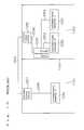
- FIG. 1is an example of an informational wiring within a residence according to the first present invention.
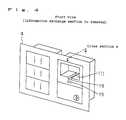
- FIG. 2is a perspective illustration of an informational outlet according to one embodiment of the first present invention viewed from the front side.
- FIG. 3is a perspective illustration of an informational outlet according to one embodiment of FIG. 2 viewed from the rear side.
- FIG. 4is a perspective illustration of an informational outlet according to one embodiment of FIG. 2 viewed from the front side with the information exchange section removed.
- FIG. 5is a perspective illustration of the information exchange section of an informational outlet according to one embodiment of the first present invention.
- FIG. 6is a schematic longitudinal cross section of an informational outlet according to one embodiment of the first present invention of FIG. 2 .
- FIG. 7is a b lock diagram showing the function of an informational outlet according to one embodiment of the first present invention
- FIG. 8is a perspective illustration of an informational outlet according to another embodiment of the first present invention viewed from the front side.
- FIG. 9is a perspective illustration showing an active informational outlet according to one embodiment of the second present invention.
- FIG. 10is a conceptual illustration showing the configuration of an active informational outlet according to one embodiment of the second present invention.
- FIG. 11is a conceptual illustration of the bite connection section of an active informational outlet according to one embodiment of the second present invention.
- FIG. 12is a conceptual illustration showing an example of the configuration of the control section of an active informational outlet according to one embodiment of the second present invention.
- FIG. 13is a conceptual illustration showing an example of the configuration of the control board of an active informational outlet according to one embodiment of the second present invention.
- FIG. 14is a conceptual illustration showing an example of the configuration of the power source board of an active informational outlet according to one embodiment of the second present invention.
- FIG. 15is a conceptual illustration showing an example of usage of an active informational outlet according to one embodiment of the second present invention.
- FIG. 16is a conceptual illustration of an example of usage of an informational outlet and a lines collection device according to the prior art.
- FIG. 17shows:
- FIG. 18shows:
- FIG. 19is a block diagram of a lines collection module according to Embodiment 7 of the third present invention.
- FIG. 20is an illustration of the attachment structure of a lines collection module according to Embodiment 7 of the third present invention.
- FIG. 21is an illustration of usage of a lines collection module according to Embodiment 7 of the third present invention.
- protrusion for pressing of protrusion for ejectionejection means
- FIG. 1shows one embodiment of an informational outlet according to the first present invention applied for the informational wiring within a residence.
- Social communication network 1such as telephone and ISDN
- the informational wiring 3branches out at a required number of informational outlets 4 located in each room, and the information is distributed to the terminals, such as TV's 5 , 6 , PC's 7 , 8 , and an electric appliance 9 , by connecting the informational outlets 4 to the terminals 5 , 6 , 7 and 8 [sic: 5 , 6 , 7 , 8 and 9 ].
- these terminalscan communicate with the social communication network or with each other of the devices in the home.
- FIG. 2is a perspective illustration of the informational outlet 4 of the present embodiment viewed form the room inside, and a power source outlet 11 is juxtaposed with a multimedia service outlet 12 for branching the informational wiring and for acquiring the information.
- the multimedia service outlet 12comprises: an outlet frame body 10 having an information exchange section exchangeable depending on the communication method such as Ethernet and IEEE 1394-1995, and an electricity supply section 14 for supplying the electric power to the information exchange section 13 .
- the outlet frame body 10further has an protrusion 15 as ejection means for easily attaching and detaching the information exchange section 13 . By pressing the protrusion 15 , the information exchange section 13 can be easily ejected from the outlet frame body 10 as described later.
- the electricity supply section 14further comprises a battery 16 for backup.
- FIG. 3is a perspective illustration of the informational outlet 4 of the present embodiment viewed form the wall face side.
- the multimedia service outlet 12is connected to informational wiring cables 17 for wiring between the adjacent multimedia service outlets and to AC cables 18 for supplying the electricity.
- an AC cable for supplying the electricitymay be installed from another power source outlet located elsewhere.
- FIG. 4is a perspective illustration of the outlet frame body 10 and so on of the informational outlet 4 according to the present embodiment viewed from the room side with the information exchange section removed.
- the multimedia service outlet 12is provided with a recess for receiving the information exchange section 13 .
- the bottom face of the recess 111is provided with a guide 19 for preventing an error insertion such as a mistake in the direction of the insertion of the information exchange section 13 .
- the information exchange section 13 sidehas a ridge 131 (see FIG. 5) corresponding to that shape.
- a guideis used for preventing an error insertion in the present embodiment, a pin or other method may be used.
- FIG. 5is a perspective illustration of the information exchange section 13 of the present embodiment.
- the information exchange section 13comprises two outlets 36 (corresponding to the first outlets of the first present invention) each for receiving an informational cable 20 from a terminal.
- An LED 21indicates the state of operation of the information exchange section 13 .
- the state of operation displayed by blinkingindicates generally the state of electrical connection or the state of communication depending on the different communication method.
- the ridge 131 mentioned aboveis formed in the bottom face of the information exchange section 13 , and in the rear face thereof, a protrusion 22 for ejection is formed for easily ejecting the information exchange section 13 .
- the protrusion 22allows the information exchange section 13 to be easily ejected in linkage with said protrusion 15 as described later.
- the rear face of the information exchange section 13is further provided with an edge connector (female) 23 (corresponding to the third connector of the first present invention).
- the edge connector 23is a connector for exchanging the signal with a wall face wiring, and may be replaced with a pin connector and so on other than the edge type one.
- FIG. 6is a longitudinal cross section of an informational outlet 13 of the present embodiment. This cross section is generally in the direction of “Cross section a” shown in FIGS. 4 and 5.
- the electricity supply section 14receives electricity from the AC cable 18 and supplies the electric power necessary for operation of the information exchange section 13 .
- the electricity supplyis conducted by electromagnetic induction method in the present embodiment.
- Numeral 27is an electromagnetic induction electricity supplying circuit of the electricity supply section 14 side, and an electromagnetic induction electricity receiving circuit 28 in accordance with that circuit is installed in the information exchange section 13 side.
- the electromagnetic induction methodrealizes the easiness in attachment and detachment of the information exchange section 13 and prevents a short circuit in the electricity supply line when the information exchange section 13 is being detached.
- other electricity supply methodsuch as pin method and edge method may be used.
- the protrusion 22 in the rear face of the information exchange section 13confronts the upper edge of a lever 26 provided in the innermost part of the recess 111 of the outlet frame body 10 and turns the lever 26 in the clockwise direction in FIG. 6 . Since the lower edge of the lever 26 is linked with the top tip of a rod section 151 , which is an extension portion of the protrusion 15 provided in the outlet frame body 10 , the protrusion 15 protrudes outward from the outlet frame body 10 .
- the rod section 151which extends from the protrusion 15 to the lever 26 , is provided with an opening section 29 .
- the opening section 29is opened when the lever 26 moves after the information exchange section 13 is installed, which permits the electricity supply from the electricity supplying circuit 27 to the electricity receiving circuit 28 by means of the electromagnetic induction, and when the lever moves correspondingly to the detachment of the information exchange section 13 , the opening section 29 is shielded so as to inhibit the electromagnetic induction. This improves the safety.
- the mechanism to open and close the opening section 29is, for example, a shutter (not shown) provided in the rod section 151 for opening and closing the opening section 29 , said shutter being hooked to a claw (not shown) fixed in the outlet frame body 10 so as to open and close the opening section 29 depending on the movement of the rod section 151 .
- an edge connector (male) 24(corresponding to the second connector of the first present invention) is formed to connect thereto.
- the edge connector 24is connected to a wiring holder 33 so as to be able to exchange information with the informational cable 17 in the wall face side connected to the wiring holder 33 .
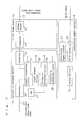
- FIG. 7is a block diagram showing the function of an informational outlet of the present invention.
- the electricity supply section 14is supplied with electricity by the AC cable 18 and supplies electric power through an AC/DC converter 30 to the electricity supplying circuit 27 .
- the backup battery 16also can supply electric power.
- the connector [sic: outlet] frame body 10is provided with the edge connector 24 and the wiring holder 33 connected thereto, and the wiring holder 33 is connected to the informational cable 17 in the wall face side.
- the information exchange section 13comprises: the edge connector 23 ; a connector 36 connected to the informational cable 20 in the room side; and a signal transmission circuit 37 , a signal transit circuit 38 , and an information processing circuit 39 all for receiving and processing the signal from the connectors 23 , 36 ; wherein said circuits perform the electrical transit, logical transit, and information processing of information, respectively.
- Respective one of the circuits 37 , 38 , 39is supplied with electric power from the electricity receiving circuit 28 .
- the state of operation of the information processingis displayed with the LED 21 .
- Th electric transitis called the hub function and to perform the electrical transit, reproduction, and distribution of signal.
- the logical transitperforms the selection of transit site in response to the addressee of the packet, such as bridges and routers, and processes a conversion if different communication methods are used, for example, when wired communication is used in the wall face and wireless network is used in the room face. In this instance, specific packets can be set not to be transited, for example, so that the access to harmful information is inhibited in the children's room.
- the information processingis, for example, the management of operation such as setting and controlling of operation of the informational outlet, which is remotely conducted by a PC or similar connected to the informational wiring.
- FIG. 8is a perspective illustration of an informational outlet according to another embodiment of the first present invention viewed from the room side.
- Thisis the example in which the electricity supply section 64 is located on a side of the multimedia service outlet 60 having a plurality of information exchange sections 61 , 62 , 63 .
- the present exampleis different from the previous embodiment in that the electricity supply is conducted from a side direction and that a plurality of information exchange sections are supplied with electricity by a single electricity supply section.
- Embodiments of the second present inventionare described below with reference to FIGS. 9-16.
- FIG. 9is a perspective illustration of an active informational outlet according to one embodiment of the second invention of the present invention, and in FIG. 9, numeral 1001 is an active informational outlet of the second invention of the present invention, 1002 is the first port, 1003 is transition wiring, and 1004 is a wall face.
- the active informational outlet 1001is the example with two of the first ports 1002 , and is embedded in the wall face 1004 and is connected through the transition wiring 1003 to transit devices such as other active informational outlets.
- a connection cable from another informational terminalis connected to the first port 1002 , and the active informational outlet 1001 performs the function of a communication transit device which allows the informational terminal connected at the first port 1002 to communicate with another informational terminal connected beyond the transition wiring but not shown, and further performs the function of a communication transit device in case that a plurality of the first ports 1002 is provided, in other words, the active informational outlet 1001 can play a role generally called a hub for LAN or similar.
- FIG. 10shows an example of the configuration of an active informational outlet of the second invention of the present invention
- numeral 1005is a control section
- 1006is an attachment support frame
- 1007is an attachment frame
- 1008is an outlet frame
- 1009is an outlet panel
- 1010is an AC connection cable
- 1011is a screw
- 1012is a bite connection section
- 1013is a bitten connection section.
- the control section 1005is for realizing the function of a communication transit device as a hub of the active informational outlet 1001 of the second invention of the present invention, as was described in Embodiment 1, and the AC connection cable 1010 is connected thereto.
- the other component membersare for embedding or attaching the control section 1005 in or to the wail face.
- the attachment frame 1007may be used for the attachment frame 1007 , the outlet frame 1008 , and outlet panel 1009 , and the outlet frame 1008 is fixed to the attachment frame 1007 using the screws 1011 , and further the outlet panel 1009 is fixed to the outlet frame 1008 by means of a plug-in structure.
- the attachment support frame 1006is for fixing the control section 1005 to the attachment frame 1007 , and the attachment frame 1007 is provided with bitten claw sections for fixing, and the bite claw sections for fixing to the attachment frame 1007 , and is provided with the screw holes for fixing the control section 1005 using screws 1011 .
- FIG. 11A conceptual illustration of the bite connection sections 1012 and the bitten connection sections 1013 is shown in FIG. 11, and in FIG. 11, since the structure is such that the bite claw section 1012 hooks on the bitten claw section 1013 , these sections are detachable after attachment.
- FIG. 12shows an example of the configuration of the control section 1005 , and in FIG. 12, numeral 1004 is a control board, 1015 is a power source board, 1016 is an electrically conductive plate, 1017 is the second port, 1018 is an AC supplied section, 1019 is a DC supply section, 1020 is a DC supplied section, 1021 is a DC connection cable, 1022 is a control side spacer, 1023 is a power-source side spacer, 1024 is a control FG point, 1025 is a power source FG point, and 1026 is an FG pattern.
- numeral 1004is a control board
- 1015is a power source board
- 1016is an electrically conductive plate
- 1017is the second port
- 1018is an AC supplied section
- 1019is a DC supply section
- 1020is a DC supplied section
- 1021is a DC connection cable
- 1022is a control side spacer
- 1023is a power-source side spacer
- 1024is
- FIG. 12shows the example of the form in which the control board 1014 and the power source board 1015 are separated and in which the control board 1014 has two of the second ports 1017 .
- an transition wiring 1003is connected to the second port 1017 , the control board 1014 realizes the hub function, and the power source board 1015 supplies the DC power source necessary for the control board 1014 to the control board 1014 by converting the AC power source.
- electromagnetic radiation noise from the power source board 1015is one of the noise sources causing the malfunctioning of the control board 1014 .
- a generally used techniqueis to shield between the control board 1014 and the power source board 1015 so that the electromagnetic rays from the power source board 1015 do not reach at the control board 1014 , accordingly, anti-noise treatment was conducted by providing the electrically conductive plate 1016 as the electrostatic shield between the control board 1014 and the power source board 1015 .
- the connection between the electrically conductive plate 1016 and the FGis accomplished by the following route: the control FG point 1024 of the control board 1014 and the electrically conductive plate 1016 are interconnected via the control side spacer 1022 ; the power source FG point 1025 of the power source board 1015 and the electrically conductive plate 1016 via the power-source side spacer 1023 ; the control FG point 1024 and the DC supplied section 1020 through a wiring pattern; the power source FG point 1025 and the DC supply section 1019 through a wiring pattern; the AC supplied section 1018 and the DC supply section 1019 through a wiring pattern; and the DC supply section 1019 and the DC supplied section 1020 through the DC connection cable 1021 .
- the electrically conductive plate 1016is for shielding the phenomenon that the electromagnetic radiation noise generated in the power source board 1015 reaches at the control board 1014 , if opening exist, the leakage through the openings occurs. Therefore, the number of openings in the electrically conductive plate 1016 is preferred to be a minimum. Thus, it is preferred that the electrically conductive plate 1016 does not have openings exceeding the total number of the number of the control FG points 1025 and the number of the power source FG points 1026 .
- FIG. 12shows the example with two holes each.
- FIG. 13shows the configuration of the control board 1014 , and in FIG. 13, numeral 1027 is a DC power source supply terminal, 1028 is an FG connection terminal, 1029 is a DC supplied section, 1030 is a control section, 1031 is a reset section, 1032 is a clock section, and 1033 is a filter section.
- control board 1014In the control board 1014 mentioned above, the action thereof is described below as well as the effect thereof.
- control section 1030 having the hub functioncontrols the signal between the first port 1002 and the second port 1017 , wherein the reset signal is supplied from the reset section 1031 and the clock signal is supplied from the clock section 1032 , and wherein the required power source is supplied from the DC power source supplied terminal 1027 of the DC supplied section 1029 .
- the control section 1030is capable of signal processing according to Ethernet 10BASE-T or Fast Ethernet 100BASE-T of IEEE 802.3 Standard, and the signal flows in either direction from the first port 1002 to the second port 1017 or from the second port 1017 to the first port 1002 .
- the control section 1030may be one that communicates according to IEEE 1394 Standard.
- the filter sections 1033are located between the first port 1002 and the control section 1030 and between the control section 1030 and the second port 1017 , and electrically insulate between the control section 1030 and the cable side of both of the first port 1002 and the second ports 1017 , and further have the function of noise elimination.
- the shells of the first port 1002 and the second ports 1017are connected to the FG connection terminal 1028 of the DC supplied section 1029 through a wiring pattern, whereby the noise is purged into the FG.
- FIG. 14shows the configuration of the power source board 1015 , and in FIG. 14, numeral 1034 is an AC supplied terminal, 1035 is an FG terminal, 1036 is a DC supply terminal, 1037 is an FG terminal, 1038 is an FG connection wiring pattern, 1039 is an AC filter section, 1040 is an AC/DC conversion section, and 1041 is a DC filter section.
- the AC power source being input from the AC supplied terminal [sic: 1034 ] of the AC supplied section 1018undergoes noise eliminationby the AC filter section 1039 , then is converted into DC power source by the AC/DC conversion section 1040 , and after that,undergoes noise eliminationby the DC filter section 1041 and is connected to the DC supply terminal 1036 of the DC supply section 1019 .
- the FG terminal 1035 and the FG terminal 1037are interconnected through the FG connection wiring pattern 1038 .
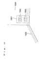
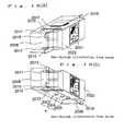
- FIG. 15shows an example of usage of the active informational outlet 1001 of the second present invention
- numeral 1042is an active informational outlet A
- 1043is the second port
- 1044is the first port
- 1045is an informational terminal A
- 1046is a connection cable A
- 1047is an active informational out let B
- 1048is the second port
- 1049is the first port
- 1050is an informational terminal B
- 1051is an informational terminal C
- 1052is a connection cable B
- 1053is a connection cable C
- 1054is a transition cable
- 1101is a room A
- 1102is a room B
- 1103is a wall.
- the room A 1101 and the room B 1102are partitioned with the wall 1103 , wherein the informational terminal A 1045 in the room A 1101 is connected to the first port 1044 of the active informational outlet A 1042 through the connection cable A 1046 , and the informational terminal B 1050 in the room B 1102 is connected to the first port 1049 of the active informational outlet B 1047 through the connection cable B 1052 , and the informational terminal C 1051 is connected to another of the first ports 1049 of the active informational outlet B 1047 through the connection cable C 1053 , further wherein the second port 1043 of the active informational outlet A 1042 and the second port 1048 of the active informational outlet B 1047 are interconnected through the transition wiring 1054 .
- the transition wiring 1054is for connecting the active informational outlet A 1042 and the active informational outlet B 1047 , and does not need reconnection after the initial connection, and hence, may be installed within the wall face.
- the informational terminal A 1045 , informational terminal B 1050 , and informational terminal C 1051can communicate only by being connected to the active informational outlet A 1042 and active informational outlet B 1047 , which are located respectively in the room A 1101 and room B 1102 , using the connection cable A 1046 , connection cable B 1052 or connection cable C 1053 .
- the present inventioncan be implemented in the form in which the control board 1014 and the power source board 1015 are integrated.
- the electrically conductive plate 1016 , the control side spacer 1022 , the power-source side spacer 1023 , the control FG point 1024 , the power-source FG point 1025 , and the FG pattern 1026are unnecessary, and the DC supply section 1019 , DC supplied section [sic: 1020 ] and the DC connection cable connecting them are formed in the wiring pattern.
- the present inventioncan be implemented in the embodiment in which the power source board 1015 itself is enclosed in a case having an opening section only for allowing at least the AC connection cable 1010 and DC connection cable 1021 to pass through, and further the present invention can also be implemented in the embodiment in which the control board 1014 , power source board 1015 , and electrically conductive plate 1016 are enclosed in a case having an opening section only for allowing at least the AC connection cable 1010 , the cable connected to the first port 1002 , and the cable connected to the second port 17 [sic: 1017 ] to pass through.
- Embodiment of the second present inventionis shown with the example with two of the first ports 1002 and two of the second ports 1017 , the present invention can be implemented in the embodiment with one of the first ports or one of the second ports.
- the Embodiment of the second present inventionis shown with the example in which the first port 1002 is one corresponding to a non-shielded cable, the present invention can be implemented in the embodiment in which the first port is one corresponding to a shielded cable.
- the Embodiment of the second present inventionis shown with the example in which the second port 1017 is one corresponding to a non-shielded cable, the present invention can be implemented in the embodiment in which the second port is one corresponding to a shielded cable or an optical fiber made of such as plastics or glass.
- control board and said power source board and said electrically conductive plateis preferred to be 50 cm ⁇ 95 cm [sic: 50 mm ⁇ 95 mm] or less.
- Embodiments of the third present inventionare described below with reference to FIGS. 17-21.
- FIG. 17shows the external appearance of a lines collection module according to Embodiment 7 of the third present invention.
- (a)is the front view of a lines collection module 2022
- (b)is the bottom view thereof
- (c)is the rear view thereof
- (d)is the side view thereof
- numeral 2001is the first port provided in the front face
- 2002is the second port provided in the rear face
- 2003is a DC (+) supply terminal (DC, below) provided in the bottom face
- 2004is a DC ( ⁇ ) supply terminal (SG, below)
- 2005is a frame ground terminal (FG, below)
- 2006is a power source supply terminal provided in the bottom face and comprised of the DC 2003 , SG 2004 , and FG 2005 .
- a bite claw section 2019is described later.
- a non-shielded cable (connection cable, below) from an informational terminalis connected to the first port 2001 , and this connection allows communication according to 10BASE-T or 100BASE-T of IEEE 802 Standard or according to IEEE 1394 Standard.
- a non-shielded cable(transition wiring, below) connected to another lines collection device or another informational terminal or similar is connected to the second port 2002 .
- the power source supply terminal 2006is provided in the bottom face, and the wiring sequence and location of the DC 2003 , SG 2004 , and FG 2005 are arbitrary.
- FIG. 18is a see-through illustration showing the internal structure of a lines collection module according to Embodiment 7 of the third present invention.
- (a)is a see-through illustration viewed from above
- (b)is a see-through illustration viewed from below
- numeral 2007is a control board A
- 2008is a control board B
- 2009is a power source board.
- the same reference numerals as those in FIG. 17indicate the similar components to those in FIG. 17 .
- the control board A 2007is provided in the top face side of the lines collection module 2022 , the control board B 2008 is provided in the side face side, and the power source board 2009 is provided in the bottom face side.
- control board A 2007 , control board B 2008are circuit boards having means for controlling the communication of the first port 2001 and the second port 2002 , and is supplied with the required power source by the power source board 2009 .
- the first port 2001 , the second port 2002 , control board A 2007 , control board B 2008 , and power source board 2009are respectively fixed with resin or similar, and the outer face of the resin forms the shape of the lines collection module shown in FIG. 17 .
- this molding with resin or similaris formed by a material having a good thermal conductivity, the molding yields the effect of releasing the heat produced by the high speed operation of the circuit and components of the control board A 2007 and control board B 2008 , and at the same time, the molding results the effect of preventing the failure of the control board A 2007 and control board B 2008 because the molding prevents the entry of water and dust and the like.
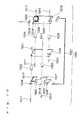
- FIG. 19is a block diagram showing the configuration of the lines collection module in Embodiment 7 of the third present invention.
- the control board A 2007is provided with a connector A 2010 , control section 2016 , the first filter section 2017 , and the second filter section 2018 ;
- the control board B 2008is provided with a connector 1 B 2011 , a connector 2 B 2012 , a clock section 2014 , and a reset section 2015 ;
- the power source board 2009has a circuit and components for supplying the electricity to the control board B 2008 and control board A 2007 , and comprises a connector C 2013 and a power source supply terminal 2006 .
- the same reference numerals as those in FIGS. 17-18indicate the similar components.
- control board A 2007 and control board B 2008are interconnected by the connection of the connector A 2010 and connector 1 B 2011 , and similarly the control board B 2008 and power source board 2009 by the connection of the 2 B 2012 and connector C 2013 .
- first port 2001 and the second port 2002are directly interconnected electrically, and that the control board A 2007 is removed, and that the power source board 2009 and control board B 2008 are unconnected. This because the control board A 2007 is added to supply the power source if necessary.
- the control section 2016controls the communication between the first port 2001 and the second port 2002 , wherein the clock signal to the control section 2016 is supplied from the clock section 2014 of the control board B 2008 , and the reset signal is supplied from the reset section 2015 of the control board B 2008 .
- the communication according to 10BASE-T or 100BASE-T or IEEE 1394uses 8-pin connectors but uses only four pins thereof in the actual communication according to the standard, and accordingly, the second port is provided with an 8-pin jack connector having four pins used by the UP link cable and another four pins used by the DOWN link cable together in one so that two communication paths can be connected to the second port. The connection is made so that the DOWN link and UP link become twisted pairs.
- the first filter section 2017 and the second filter section 2018for example, conduct the treatment of reducing the electric signal noise flowing in the control section 2016 and the first port 2001 or in the second port 2002 and control section 16 [sic: 2016 ]; and conduct the treatment of electrically isolating the first filter port 2001 and the second port 2002 and control section 2016 and the like; and are provided in the control board A 2007 and control board B 2008
- FIG. 20shows the attachment structure of a lines collection module according to Embodiment 1 of the third present invention
- numeral 2019is a bite claw section
- 2020is a bitten claw section
- 2021is an attachment frame
- 2022is a lines collection module.
- the attachment frame 2021is a commercial one and provided with the bitten claw sections 2020 for attaching a module such as a commercial-line AC power source outlet and a power source switch or the like, whereby three modules can be attached.
- the lines collection module 2022 of the third present inventionis provided with the bite claw sections 2019 for mating with the bitten claw sections 2020 of the attachment frame 2021 for attaching the lines collection module 2022 .
- the dimension of the lines collection module 2022is 22 mm length ⁇ 45 mm width ⁇ 40 mm depth or less, three modules can be attached to the attachment frame 2021 .
- FIG. 21shows an example of usage of a lines collection module according to Embodiment 7 of the third present invention.
- numeral 2026is a connection cable A
- 2027is a connection cable B
- 2028is a connection cable C
- 2029 a, 2029 b, 2029 care transition wiring
- 2030is a lines collection module 1 A
- 2031is a lines collection module 2 A
- 2032is an informational outlet A
- 2033is a lines collection module 1 B
- 2034is a lines collection module 2 B
- 2035is an informational outlet B
- 2051 , 2052 , 2055 , 2056are the first ports
- 2053 , 2054 , 2057 , 2058are the second ports
- 2101is a room A
- 2102is a room B
- 2103is a wall.
- the informational outlet A 2032is constructed with: the lines collection module 1 A 2030 having the first port 2051 and the second port 2053 ; and the lines collection module 2 A 2031 having the first port 2052 and the second port 2054 .
- the informational outlet B 2035is constructed with: the lines collection module 1 B 2033 having the first port 2055 and the second port 2057 ; and the lines collection module 2 B 2034 having the first port 2056 and the second port 2058 .
- FIG. 21shows an example of usage in which each of the informational outlets is provided with two of the lines collection modules according to Embodiment 7 of the third present invention.
- the informational terminal A 2023 located in the room A 2101is connected to the first port 2052 of the lines collection module 2 A 2031 of the informational outlet A 2032 via the connection cable A 2026
- the informational terminal B 2024 located in the room B 2102is connected to the first port 2055 of the lines collection module 1 B 2033 of the informational outlet B 2035 via the connection cable B 2027
- the informational terminal C 2025is connected to the first port 2056 of the lines collection module 2 B 2034 via the connection cable C 2028 .
- the lines collection module 2 A 2031 of the informational outlet A 2032 and the lines collection module 1 B 2033 , lines collection module 2 B 2034 both of the informational outlet B 2035are interconnected by the transition wiring 2029 a, 2029 b, and 2029 c. That is, the transition wiring 2029 a connects the UP link of the port 2054 and the DOWN link of the port 2058 , and the transition wiring 2029 a [sic: 2029 b ] connects the UP link of the port 2054 and the DOWN link of the port 2058 , and further the transition wiring 2029 b [sic: 2029 c ] connects the UP link of the port 2057 and the DOWN link of the port 2054 .
- the informational terminal A 2023can communicate with the informational terminal B 2024 and informational terminal C 2025 located in another room, and even when any of the informational terminal A 2023 , informational terminal B 2024 , and informational terminal C 2025 changes the room, it can communicate with other informational terminals only by connecting to one of the lines collection modules located in the informational outlets in the respective rooms.
- control board A 2007was provided in the top face side of the lines collection module 2022 and in which the power source board 2009 in the bottom face side and further in which the power source supply terminal 2006 in the bottom face side
- present inventioncan be similarly implemented in another configuration, for example, in which the control board A 2007 is provided in the bottom face side and in which the power source board 2009 in the top face side and further in which the power source supply terminal 2006 in the top face side.
- connection cable connected to the first port 2001 and the connection cable connected to the second port 2002were non-shielded cables
- present inventioncan be similarly implemented with other shielded cables.
- the shield of the shielded cablehas a contact point at the mating section with the connector, and has the contact structure in which the shells and the shield of the shielded cable are electrically contacted by the action that the shield contacts to the shells provided in the mating sections of the first port 2001 and the second port 2002 when the shielded cable is connected to the first port 2001 and the second port 2002 ; and further, the shells of the first port and the second port are electrically connected to the FG 2005 .
- first port 2001 , the second port 2002 , control board A 2007 , control board B 2008 , power source board 2009 , and power source supply terminal 2006have a shape formed by molding with resin or similar, it is also permissible to form it by putting the first port 2001 , the second port 2002 , control board A 2007 , control board B 2008 , power source board 2009 , and power source supply terminal 2006 in an electrically conductive case having at least an opening section allowing the access to the power source supply terminal 2006 and by enclosing the surrounding of the case with resin or similar.
- Said electrically conductive casecan be electrically connected to the FG 2005 of the power source supply terminal 2006 .
- the electrically conductive caseworks as an electrostatic shield and has the effect of preventing the malfunction due to noise.
- the first present inventioncan be easily treated without rewiring work, even if change the communication method, and the equipment can be of wall built-in and of simple design, and further, users can assuredly use it in the same sense as that of the life lines.
- the second present inventionyields the prominent effect of providing an active informational outlet allowing the construction of noise tolerant network environment using a small amount of equipment and having orderly wiring.
- a lines collection module and an informational outlet according to the third present inventionyield the prominent effect that the communication between informational terminals located in different rooms is allowed using inexpensive wiring that does not spoil the beauty.
Landscapes
- Engineering & Computer Science (AREA)
- Signal Processing (AREA)
- Computer Networks & Wireless Communication (AREA)
- Structure Of Telephone Exchanges (AREA)
Abstract
Description
Claims (8)
Applications Claiming Priority (6)
| Application Number | Priority Date | Filing Date | Title |
|---|---|---|---|
| JP08181099AJP3522574B2 (en) | 1999-03-25 | 1999-03-25 | Information outlet |
| JP11-081810 | 1999-03-25 | ||
| JP11-211265 | 1999-07-26 | ||
| JP11211265AJP2001035608A (en) | 1999-07-26 | 1999-07-26 | Active information outlet |
| JP25239699AJP2001076828A (en) | 1999-09-07 | 1999-09-07 | Concentrator module |
| JP11-252396 | 1999-09-07 |
Publications (1)
| Publication Number | Publication Date |
|---|---|
| US6420964B1true US6420964B1 (en) | 2002-07-16 |
Family
ID=27303705
Family Applications (1)
| Application Number | Title | Priority Date | Filing Date |
|---|---|---|---|
| US09/536,313Expired - LifetimeUS6420964B1 (en) | 1999-03-25 | 2000-03-27 | Informational outlet and lines collection module |
Country Status (1)
| Country | Link |
|---|---|
| US (1) | US6420964B1 (en) |
Cited By (35)
| Publication number | Priority date | Publication date | Assignee | Title |
|---|---|---|---|---|
| US20050111636A1 (en)* | 1999-07-20 | 2005-05-26 | Serconet, Ltd | Network for telephony and data communication |
| US20050176275A1 (en)* | 2004-02-05 | 2005-08-11 | Panamax | Modular signal and power connection device |
| US20060276144A1 (en)* | 2005-06-02 | 2006-12-07 | Jack Campbell | Modular electrical component system combining power line voltage and low voltage elements |
| US7197028B2 (en) | 2000-04-18 | 2007-03-27 | Serconet Ltd. | Telephone communication system over a single telephone line |
| US7221679B2 (en) | 1998-07-28 | 2007-05-22 | Serconet Ltd. | Local area network of serial intelligent cells |
| US20070220560A1 (en)* | 2006-03-14 | 2007-09-20 | Audioplex Technology Incorporated | Audio/video transmission system and method |
| US20080019501A1 (en)* | 2006-06-28 | 2008-01-24 | Miller William V Iii | Method for extending Ethernet over twisted pair conductors and to the telephone network and plug-in apparatus for same employing standard mechanics |
| US20080030971A1 (en)* | 2006-08-01 | 2008-02-07 | Tyco Electronics Corporation | Wall-Mounted Network Outlet |
| US20080196936A1 (en)* | 2005-07-08 | 2008-08-21 | Matsushita Electric Works, Ltd. | Base Unit for Dual Wiring System |
| US7453895B2 (en) | 2001-10-11 | 2008-11-18 | Serconet Ltd | Outlet with analog signal adapter, a method for use thereof and a network using said outlet |
| WO2008156930A1 (en)* | 2007-06-19 | 2008-12-24 | Lastar, Inc. | Wall plate assembly with integral universal serial bus module |
| US7522615B2 (en) | 2002-11-13 | 2009-04-21 | Serconet, Ltd. | Addressable outlet, and a network using same |
| US20090103271A1 (en)* | 2007-10-19 | 2009-04-23 | Sure Fire Electronical Corporation | Wall plate assembly |
| US7680255B2 (en) | 2001-07-05 | 2010-03-16 | Mosaid Technologies Incorporated | Telephone outlet with packet telephony adaptor, and a network using same |
| US7686653B2 (en) | 2003-09-07 | 2010-03-30 | Mosaid Technologies Incorporated | Modular outlet |
| US7756268B2 (en) | 2004-02-16 | 2010-07-13 | Mosaid Technologies Incorporated | Outlet add-on module |
| US20100278537A1 (en)* | 2008-09-24 | 2010-11-04 | Elbex Video Ltd. | Method and Apparatus for Connecting AC Powered Switches, Current Sensors and Control Devices Via Two Way IR, Fiber Optic and Light Guide Cables |
| US20100317223A1 (en)* | 2009-06-15 | 2010-12-16 | Byrne Norman R | Power and data adapter assembly |
| US7873058B2 (en) | 2004-11-08 | 2011-01-18 | Mosaid Technologies Incorporated | Outlet with analog signal adapter, a method for use thereof and a network using said outlet |
| US20110116750A1 (en)* | 2009-11-19 | 2011-05-19 | Terlizzi Jeffrey J | Audio jacks with optical and electrical paths |
| US20110116647A1 (en)* | 2009-11-19 | 2011-05-19 | Terlizzi Jeffrey J | Equipment with optical paths for noise cancellation signals |
| US20110116747A1 (en)* | 2009-11-19 | 2011-05-19 | Terlizzi Jeffrey J | Audio plugs with optical and electrical paths |
| US20110116751A1 (en)* | 2009-11-19 | 2011-05-19 | Terlizzi Jeffrey J | Interface accessories with optical and electrical paths |
| US20110116675A1 (en)* | 2009-11-19 | 2011-05-19 | Terlizzi Jeffrey J | Audio connectors with wavelength-division-multiplexing capabilities |
| EP2328238A1 (en)* | 2009-11-23 | 2011-06-01 | A. & H. Meyer GmbH Leuchten und Büroelektrik | Socket device for an item of furniture |
| FR2958087A1 (en)* | 2010-03-29 | 2011-09-30 | Sibecx System | CONNECTING DEVICE FOR RECEIVING INFORMATION FROM AN ELECTRIC LINE INTEGRATED IN A BRACKET OR A SUPPORT OR FOR TRANSMITTING INFORMATION ON THE ELECTRIC LINE |
| US8480429B2 (en) | 2005-06-13 | 2013-07-09 | Norman R. Byrne | Power data housing |
| US8582598B2 (en) | 1999-07-07 | 2013-11-12 | Mosaid Technologies Incorporated | Local area network for distributing data communication, sensing and control signals |
| US8620162B2 (en) | 2010-03-25 | 2013-12-31 | Apple Inc. | Handheld electronic device with integrated transmitters |
| US8755174B2 (en) | 2010-07-16 | 2014-06-17 | Ensco, Inc. | Media appliance and method for use of same |
| US8858263B2 (en) | 2011-08-08 | 2014-10-14 | Novano Corporation | Service over ethernet InterConnectable wall plate (SoEICWP) module |
| US20150109753A1 (en)* | 2013-10-21 | 2015-04-23 | Centurylink Intellectual Property Llc | Omedia Panel |
| US20160036181A1 (en)* | 2015-10-09 | 2016-02-04 | Electro-Motive Diesel, Inc. | Connector device for electronic communication system |
| US9769519B2 (en) | 2010-07-16 | 2017-09-19 | Enseo, Inc. | Media appliance and method for use of same |
| US10986165B2 (en) | 2004-01-13 | 2021-04-20 | May Patents Ltd. | Information device |
Citations (18)
| Publication number | Priority date | Publication date | Assignee | Title |
|---|---|---|---|---|
| US4863398A (en)* | 1989-01-30 | 1989-09-05 | Keptel, Inc. | Universal adapter for office wall panels |
| US4918688A (en)* | 1986-10-31 | 1990-04-17 | Convergent Technologies, Inc. | Method and apparatus for coupling computer work stations |
| US5036168A (en)* | 1988-09-09 | 1991-07-30 | Matsushita Electric Works, Ltd. | Multi-unit switch assembly |
| US5125852A (en)* | 1991-07-15 | 1992-06-30 | Superior Modular Products, Inc. | Universal electrical connector jack |
| US5599190A (en)* | 1995-01-27 | 1997-02-04 | The Whitaker Corporation | Communication wiring system including a reconfigurable outlet assembly |
| US5613874A (en)* | 1995-05-05 | 1997-03-25 | Ortronics Inc. | Snap-in designation strip for modular information management oulet |
| US5658166A (en)* | 1990-06-27 | 1997-08-19 | Digital Equipment Corporation | Modular coupler arrangement for use in a building wiring distribution system |
| US5695361A (en)* | 1995-10-09 | 1997-12-09 | The Whitaker Corporation | Low profile communications outlet |
| JPH1041032A (en) | 1996-07-19 | 1998-02-13 | Matsushita Electric Works Ltd | Network concentrator |
| JPH10208827A (en) | 1997-01-27 | 1998-08-07 | Matsushita Electric Works Ltd | Flush-mount information receptacle |
| US5831802A (en)* | 1996-06-18 | 1998-11-03 | Ahmed; Samir Omar Ramsey | Electronic circuit for automatic disconnector |
| US6039578A (en)* | 1996-04-02 | 2000-03-21 | Reltec Corporation | Network interface device for line testing |
| US6067014A (en)* | 1996-08-09 | 2000-05-23 | Wilson; Edwin P. | Cord tamper method and apparatus |
| US6104921A (en)* | 1997-10-14 | 2000-08-15 | Marconi Communications Inc. | Communications modular docking station |
| US6114632A (en)* | 1998-03-05 | 2000-09-05 | Planas, Sr.; Alberto E. | Integrated power and data communication hybrid cable assembly for local area computer network |
| US6123577A (en)* | 1996-02-06 | 2000-09-26 | Energy Transformation Systems, Inc. | Lan patch panel and wall mount unit assembly |
| US6175556B1 (en)* | 1994-06-06 | 2001-01-16 | International Business Machines Corporation | Remote powered ethernet repeater |
| US6227879B1 (en)* | 1999-12-21 | 2001-05-08 | Hon Hai Precision Ind. Co., Ltd. | Electrical connector with grounding shroud having board-locks for grasping a circuit board |
- 2000
- 2000-03-27USUS09/536,313patent/US6420964B1/ennot_activeExpired - Lifetime
Patent Citations (18)
| Publication number | Priority date | Publication date | Assignee | Title |
|---|---|---|---|---|
| US4918688A (en)* | 1986-10-31 | 1990-04-17 | Convergent Technologies, Inc. | Method and apparatus for coupling computer work stations |
| US5036168A (en)* | 1988-09-09 | 1991-07-30 | Matsushita Electric Works, Ltd. | Multi-unit switch assembly |
| US4863398A (en)* | 1989-01-30 | 1989-09-05 | Keptel, Inc. | Universal adapter for office wall panels |
| US5658166A (en)* | 1990-06-27 | 1997-08-19 | Digital Equipment Corporation | Modular coupler arrangement for use in a building wiring distribution system |
| US5125852A (en)* | 1991-07-15 | 1992-06-30 | Superior Modular Products, Inc. | Universal electrical connector jack |
| US6175556B1 (en)* | 1994-06-06 | 2001-01-16 | International Business Machines Corporation | Remote powered ethernet repeater |
| US5599190A (en)* | 1995-01-27 | 1997-02-04 | The Whitaker Corporation | Communication wiring system including a reconfigurable outlet assembly |
| US5613874A (en)* | 1995-05-05 | 1997-03-25 | Ortronics Inc. | Snap-in designation strip for modular information management oulet |
| US5695361A (en)* | 1995-10-09 | 1997-12-09 | The Whitaker Corporation | Low profile communications outlet |
| US6123577A (en)* | 1996-02-06 | 2000-09-26 | Energy Transformation Systems, Inc. | Lan patch panel and wall mount unit assembly |
| US6039578A (en)* | 1996-04-02 | 2000-03-21 | Reltec Corporation | Network interface device for line testing |
| US5831802A (en)* | 1996-06-18 | 1998-11-03 | Ahmed; Samir Omar Ramsey | Electronic circuit for automatic disconnector |
| JPH1041032A (en) | 1996-07-19 | 1998-02-13 | Matsushita Electric Works Ltd | Network concentrator |
| US6067014A (en)* | 1996-08-09 | 2000-05-23 | Wilson; Edwin P. | Cord tamper method and apparatus |
| JPH10208827A (en) | 1997-01-27 | 1998-08-07 | Matsushita Electric Works Ltd | Flush-mount information receptacle |
| US6104921A (en)* | 1997-10-14 | 2000-08-15 | Marconi Communications Inc. | Communications modular docking station |
| US6114632A (en)* | 1998-03-05 | 2000-09-05 | Planas, Sr.; Alberto E. | Integrated power and data communication hybrid cable assembly for local area computer network |
| US6227879B1 (en)* | 1999-12-21 | 2001-05-08 | Hon Hai Precision Ind. Co., Ltd. | Electrical connector with grounding shroud having board-locks for grasping a circuit board |
Cited By (108)
| Publication number | Priority date | Publication date | Assignee | Title |
|---|---|---|---|---|
| US7965735B2 (en) | 1998-07-28 | 2011-06-21 | Mosaid Technologies Incorporated | Local area network of serial intelligent cells |
| US8908673B2 (en) | 1998-07-28 | 2014-12-09 | Conversant Intellectual Property Management Incorporated | Local area network of serial intelligent cells |
| US8885660B2 (en) | 1998-07-28 | 2014-11-11 | Conversant Intellectual Property Management Incorporated | Local area network of serial intelligent cells |
| US8885659B2 (en) | 1998-07-28 | 2014-11-11 | Conversant Intellectual Property Management Incorporated | Local area network of serial intelligent cells |
| US8867523B2 (en) | 1998-07-28 | 2014-10-21 | Conversant Intellectual Property Management Incorporated | Local area network of serial intelligent cells |
| US7221679B2 (en) | 1998-07-28 | 2007-05-22 | Serconet Ltd. | Local area network of serial intelligent cells |
| US7986708B2 (en) | 1998-07-28 | 2011-07-26 | Mosaid Technologies Incorporated | Local area network of serial intelligent cells |
| US8582598B2 (en) | 1999-07-07 | 2013-11-12 | Mosaid Technologies Incorporated | Local area network for distributing data communication, sensing and control signals |
| US8929523B2 (en) | 1999-07-20 | 2015-01-06 | Conversant Intellectual Property Management Inc. | Network for telephony and data communication |
| US20050111636A1 (en)* | 1999-07-20 | 2005-05-26 | Serconet, Ltd | Network for telephony and data communication |
| US8351582B2 (en) | 1999-07-20 | 2013-01-08 | Mosaid Technologies Incorporated | Network for telephony and data communication |
| US7483524B2 (en) | 1999-07-20 | 2009-01-27 | Serconet, Ltd | Network for telephony and data communication |
| US8000349B2 (en) | 2000-04-18 | 2011-08-16 | Mosaid Technologies Incorporated | Telephone communication system over a single telephone line |
| US8559422B2 (en) | 2000-04-18 | 2013-10-15 | Mosaid Technologies Incorporated | Telephone communication system over a single telephone line |
| US7197028B2 (en) | 2000-04-18 | 2007-03-27 | Serconet Ltd. | Telephone communication system over a single telephone line |
| US7466722B2 (en) | 2000-04-18 | 2008-12-16 | Serconet Ltd | Telephone communication system over a single telephone line |
| US7397791B2 (en) | 2000-04-18 | 2008-07-08 | Serconet, Ltd. | Telephone communication system over a single telephone line |
| US8223800B2 (en) | 2000-04-18 | 2012-07-17 | Mosaid Technologies Incorporated | Telephone communication system over a single telephone line |
| US7593394B2 (en) | 2000-04-18 | 2009-09-22 | Mosaid Technologies Incorporated | Telephone communication system over a single telephone line |
| US7680255B2 (en) | 2001-07-05 | 2010-03-16 | Mosaid Technologies Incorporated | Telephone outlet with packet telephony adaptor, and a network using same |
| US7860084B2 (en) | 2001-10-11 | 2010-12-28 | Mosaid Technologies Incorporated | Outlet with analog signal adapter, a method for use thereof and a network using said outlet |
| US7453895B2 (en) | 2001-10-11 | 2008-11-18 | Serconet Ltd | Outlet with analog signal adapter, a method for use thereof and a network using said outlet |
| US7953071B2 (en) | 2001-10-11 | 2011-05-31 | Mosaid Technologies Incorporated | Outlet with analog signal adapter, a method for use thereof and a network using said outlet |
| US7889720B2 (en) | 2001-10-11 | 2011-02-15 | Mosaid Technologies Incorporated | Outlet with analog signal adapter, a method for use thereof and a network using said outlet |
| US7911992B2 (en) | 2002-11-13 | 2011-03-22 | Mosaid Technologies Incorporated | Addressable outlet, and a network using the same |
| US7522615B2 (en) | 2002-11-13 | 2009-04-21 | Serconet, Ltd. | Addressable outlet, and a network using same |
| US7990908B2 (en) | 2002-11-13 | 2011-08-02 | Mosaid Technologies Incorporated | Addressable outlet, and a network using the same |
| US8295185B2 (en) | 2002-11-13 | 2012-10-23 | Mosaid Technologies Inc. | Addressable outlet for use in wired local area network |
| US7873062B2 (en) | 2003-07-09 | 2011-01-18 | Mosaid Technologies Incorporated | Modular outlet |
| US7688841B2 (en) | 2003-07-09 | 2010-03-30 | Mosaid Technologies Incorporated | Modular outlet |
| US7867035B2 (en) | 2003-07-09 | 2011-01-11 | Mosaid Technologies Incorporated | Modular outlet |
| US7686653B2 (en) | 2003-09-07 | 2010-03-30 | Mosaid Technologies Incorporated | Modular outlet |
| US8591264B2 (en) | 2003-09-07 | 2013-11-26 | Mosaid Technologies Incorporated | Modular outlet |
| US7690949B2 (en) | 2003-09-07 | 2010-04-06 | Mosaid Technologies Incorporated | Modular outlet |
| US8235755B2 (en) | 2003-09-07 | 2012-08-07 | Mosaid Technologies Incorporated | Modular outlet |
| US8360810B2 (en) | 2003-09-07 | 2013-01-29 | Mosaid Technologies Incorporated | Modular outlet |
| US8092258B2 (en) | 2003-09-07 | 2012-01-10 | Mosaid Technologies Incorporated | Modular outlet |
| US10986165B2 (en) | 2004-01-13 | 2021-04-20 | May Patents Ltd. | Information device |
| US20050176275A1 (en)* | 2004-02-05 | 2005-08-11 | Panamax | Modular signal and power connection device |
| US20050176274A1 (en)* | 2004-02-05 | 2005-08-11 | Hoops Gerald B. | Modular signal and power connection device |
| US6932624B1 (en)* | 2004-02-05 | 2005-08-23 | Panamax | Modular signal and power connection device |
| US6979205B2 (en)* | 2004-02-05 | 2005-12-27 | Panamax | Modular signal and power connection device |
| US8565417B2 (en) | 2004-02-16 | 2013-10-22 | Mosaid Technologies Incorporated | Outlet add-on module |
| US8611528B2 (en) | 2004-02-16 | 2013-12-17 | Mosaid Technologies Incorporated | Outlet add-on module |
| US7881462B2 (en) | 2004-02-16 | 2011-02-01 | Mosaid Technologies Incorporated | Outlet add-on module |
| US8542819B2 (en) | 2004-02-16 | 2013-09-24 | Mosaid Technologies Incorporated | Outlet add-on module |
| US7756268B2 (en) | 2004-02-16 | 2010-07-13 | Mosaid Technologies Incorporated | Outlet add-on module |
| US8243918B2 (en) | 2004-02-16 | 2012-08-14 | Mosaid Technologies Incorporated | Outlet add-on module |
| US7873058B2 (en) | 2004-11-08 | 2011-01-18 | Mosaid Technologies Incorporated | Outlet with analog signal adapter, a method for use thereof and a network using said outlet |
| US20060276144A1 (en)* | 2005-06-02 | 2006-12-07 | Jack Campbell | Modular electrical component system combining power line voltage and low voltage elements |
| US8480429B2 (en) | 2005-06-13 | 2013-07-09 | Norman R. Byrne | Power data housing |
| US20080196936A1 (en)* | 2005-07-08 | 2008-08-21 | Matsushita Electric Works, Ltd. | Base Unit for Dual Wiring System |
| US20090134716A1 (en)* | 2005-07-08 | 2009-05-28 | Matsushita Electric Works, Ltd. | Dual Wiring System |
| US20090051505A1 (en)* | 2005-07-08 | 2009-02-26 | Matsushita Electric Works, Ltd. | Function Unit for Dual Wiring System |
| US7994436B2 (en) | 2005-07-08 | 2011-08-09 | Panasonic Electric Works Co., Ltd. | Base unit for dual wiring system |
| US20090209136A1 (en)* | 2005-07-08 | 2009-08-20 | Matsushita Electric Works , Ltd. | Dual Wiring System |
| US8277254B2 (en)* | 2005-07-08 | 2012-10-02 | Panasonic Corporation | Dual wiring system |
| US7772717B2 (en)* | 2005-07-08 | 2010-08-10 | Panasonic Electric Works Co., Ltd. | Dual wiring system |
| US8238755B2 (en)* | 2005-07-08 | 2012-08-07 | Panasonic Corporation | Dual wiring system |
| US20090110407A1 (en)* | 2005-07-08 | 2009-04-30 | Matsushita Electric Works, Ltd. | Dual Wiring System |
| US8138636B2 (en) | 2005-07-08 | 2012-03-20 | Panasonic Electric Works Co., Ltd. | Function unit for dual wiring system |
| US20070220560A1 (en)* | 2006-03-14 | 2007-09-20 | Audioplex Technology Incorporated | Audio/video transmission system and method |
| US8837712B2 (en) | 2006-06-28 | 2014-09-16 | Hubbell Incorporated | Method for extending Ethernet over twisted pair conductors and to the telephone network and plug-in apparatus for same employing standard mechanics |
| US20080019501A1 (en)* | 2006-06-28 | 2008-01-24 | Miller William V Iii | Method for extending Ethernet over twisted pair conductors and to the telephone network and plug-in apparatus for same employing standard mechanics |
| US8023642B2 (en) | 2006-06-28 | 2011-09-20 | Hubbell Incorporated | Method for extending ethernet over twisted pair conductors and to the telephone network and plug-in apparatus for same employing standard mechanics |
| US7612653B2 (en)* | 2006-08-01 | 2009-11-03 | Tyco Electronics Corporation | Wall-mounted network outlet |
| US20080030971A1 (en)* | 2006-08-01 | 2008-02-07 | Tyco Electronics Corporation | Wall-Mounted Network Outlet |
| WO2008156930A1 (en)* | 2007-06-19 | 2008-12-24 | Lastar, Inc. | Wall plate assembly with integral universal serial bus module |
| US7741562B2 (en) | 2007-06-19 | 2010-06-22 | Lastar Inc. | Wall plate assembly with integral universal serial bus module |
| US20100240250A1 (en)* | 2007-06-19 | 2010-09-23 | Jennifer Dawn Crotinger | Wall plate assembly with integral universal serial bus module |
| US20080318474A1 (en)* | 2007-06-19 | 2008-12-25 | Jennifer Dawn Crotinger | Wall plate assembly with integral universal serial bus module |
| US7915529B2 (en) | 2007-06-19 | 2011-03-29 | Lastar, Inc. | Wall plate assembly with integral universal serial bus module |
| US7637772B2 (en)* | 2007-10-19 | 2009-12-29 | Sure-Fire Electrical Corporation | Wall plate assembly |
| US20090103271A1 (en)* | 2007-10-19 | 2009-04-23 | Sure Fire Electronical Corporation | Wall plate assembly |
| US20100278537A1 (en)* | 2008-09-24 | 2010-11-04 | Elbex Video Ltd. | Method and Apparatus for Connecting AC Powered Switches, Current Sensors and Control Devices Via Two Way IR, Fiber Optic and Light Guide Cables |
| US8331794B2 (en)* | 2008-09-24 | 2012-12-11 | Elbex Video Ltd. | Method and apparatus for connecting AC powered switches, current sensors and control devices via two way IR, fiber optic and light guide cables |
| US8175463B2 (en)* | 2008-09-24 | 2012-05-08 | Elbex Video Ltd. | Method and apparatus for connecting AC powered switches, current sensors and control devices via two way IR, fiber optic and light guide cables |
| US20120183298A1 (en)* | 2008-09-24 | 2012-07-19 | Elbex Video Ltd. | Method and apparatus for connecting ac powered switches, current sensors and control devices via two way ir, fiber optic and light guide cables |
| US8331795B2 (en)* | 2008-09-24 | 2012-12-11 | Elbex Video Ltd. | Method and apparatus for connecting AC powered switches, current sensors and control devices via two way IR, fiber optic and light guide cables |
| US20120207481A1 (en)* | 2008-09-24 | 2012-08-16 | Elbex Video Ltd. | Method and apparatus for connecting ac powered switches, current sensors and control devices via two way ir, fiber optic and light guide cables |
| US20100317223A1 (en)* | 2009-06-15 | 2010-12-16 | Byrne Norman R | Power and data adapter assembly |
| US8444432B2 (en) | 2009-06-15 | 2013-05-21 | Norman R. Byrne | Power and data adapter assembly |
| US20110116675A1 (en)* | 2009-11-19 | 2011-05-19 | Terlizzi Jeffrey J | Audio connectors with wavelength-division-multiplexing capabilities |
| US20110116747A1 (en)* | 2009-11-19 | 2011-05-19 | Terlizzi Jeffrey J | Audio plugs with optical and electrical paths |
| US8577195B2 (en) | 2009-11-19 | 2013-11-05 | Apple Inc. | Interface accessories with optical and electrical paths |
| US20110116647A1 (en)* | 2009-11-19 | 2011-05-19 | Terlizzi Jeffrey J | Equipment with optical paths for noise cancellation signals |
| US8651750B2 (en)* | 2009-11-19 | 2014-02-18 | Apple Inc. | Audio connectors with optical structures and electrical contacts |
| US8682003B2 (en) | 2009-11-19 | 2014-03-25 | Apple Inc. | Equipment with optical paths for noise cancellation signals |
| US8718294B2 (en) | 2009-11-19 | 2014-05-06 | Apple Inc. | Audio connectors with wavelength-division-multiplexing capabilities |
| US20110116750A1 (en)* | 2009-11-19 | 2011-05-19 | Terlizzi Jeffrey J | Audio jacks with optical and electrical paths |
| US8573861B2 (en) | 2009-11-19 | 2013-11-05 | Apple Inc. | Audio jacks with optical and electrical paths |
| US20110116751A1 (en)* | 2009-11-19 | 2011-05-19 | Terlizzi Jeffrey J | Interface accessories with optical and electrical paths |
| EP2328238B1 (en) | 2009-11-23 | 2015-11-11 | A. & H. Meyer GmbH Leuchten und Büroelektrik | Socket device for an item of furniture |
| EP2328238A1 (en)* | 2009-11-23 | 2011-06-01 | A. & H. Meyer GmbH Leuchten und Büroelektrik | Socket device for an item of furniture |
| US8620162B2 (en) | 2010-03-25 | 2013-12-31 | Apple Inc. | Handheld electronic device with integrated transmitters |
| FR2958087A1 (en)* | 2010-03-29 | 2011-09-30 | Sibecx System | CONNECTING DEVICE FOR RECEIVING INFORMATION FROM AN ELECTRIC LINE INTEGRATED IN A BRACKET OR A SUPPORT OR FOR TRANSMITTING INFORMATION ON THE ELECTRIC LINE |
| WO2011121231A1 (en)* | 2010-03-29 | 2011-10-06 | Sibecx System | Connection device for receiving information coming from an electrical line integrated into a support or for sending information to the electrical line |
| US9095057B2 (en) | 2010-07-16 | 2015-07-28 | Enseo, Inc. | Media appliance and method for use of same |
| US9007744B2 (en) | 2010-07-16 | 2015-04-14 | Enseo, Inc. | Media appliance and method for use of same |
| US9252572B2 (en) | 2010-07-16 | 2016-02-02 | Enseo, Inc. | Media appliance and method for use of same |
| US9769519B2 (en) | 2010-07-16 | 2017-09-19 | Enseo, Inc. | Media appliance and method for use of same |
| US10616641B2 (en) | 2010-07-16 | 2020-04-07 | Enseo, Inc. | Media appliance and method for use of same |
| US8755174B2 (en) | 2010-07-16 | 2014-06-17 | Ensco, Inc. | Media appliance and method for use of same |
| US8858263B2 (en) | 2011-08-08 | 2014-10-14 | Novano Corporation | Service over ethernet InterConnectable wall plate (SoEICWP) module |
| US20150109753A1 (en)* | 2013-10-21 | 2015-04-23 | Centurylink Intellectual Property Llc | Omedia Panel |
| US9716924B2 (en)* | 2013-10-21 | 2017-07-25 | Centurylink Intellectual Property Llc | Omedia panel |
| US10085076B2 (en) | 2013-10-21 | 2018-09-25 | Centurylink Intellectual Property Llc | Omedia panel |
| US20160036181A1 (en)* | 2015-10-09 | 2016-02-04 | Electro-Motive Diesel, Inc. | Connector device for electronic communication system |
Similar Documents
| Publication | Publication Date | Title |
|---|---|---|
| US6420964B1 (en) | Informational outlet and lines collection module | |
| US11715920B2 (en) | Single pair ethernet connector system | |
| US8894296B2 (en) | Powered cat 5 plug and socket | |
| US6154774A (en) | In-wall data translator and a structured premise wiring environment including the same | |
| EP0806843A2 (en) | Contact apparatus for network | |
| US7612653B2 (en) | Wall-mounted network outlet | |
| EP2218228B1 (en) | Modular powerline adapters and methods of use | |
| TWI564698B (en) | A power distribution unit and a communication device associated therewith, and a power distribution system | |
| JP2010501110A (en) | Photoelectric plug and outlet | |
| TW200530786A (en) | Module with interchangeable card | |
| WO2006000261A1 (en) | Jack connector assembly having circuitry components integrated for providing poe-functionality | |
| US20100194539A1 (en) | Power socket fascia | |
| US20240243530A1 (en) | Network cable connector with switch control | |
| CN100594739C (en) | Patch board with modules | |
| US20070082550A1 (en) | Shielded connector module housing with heatsink | |
| JP3522574B2 (en) | Information outlet | |
| CN221408873U (en) | Internet information acquisition exchange box | |
| GB2441798A (en) | Adaptor for power lines communication | |
| EP2128938A1 (en) | Jack Adapter in the Field of Telecommunication and Data Transmission | |
| CN222015878U (en) | A power distribution unit | |
| KR20010051458A (en) | Connector socket, connector plug and assembly thereof | |
| CN222380983U (en) | Photoelectric hybrid flange connector, photoelectric hybrid flange connection device and gateway device | |
| CN216487904U (en) | Circuit breaker connection structure | |
| CN222637958U (en) | A line output device for a power cabinet | |
| CN217116643U (en) | Subway network control system |
Legal Events
| Date | Code | Title | Description |
|---|---|---|---|
| AS | Assignment | Owner name:MATSUSHITA ELECTRIC INDUSTRIAL CO., LTD., JAPAN Free format text:ASSIGNMENT OF ASSIGNORS INTEREST;ASSIGNORS:NISHIKAWA, YOSHIKANE;WADA, TETSUYA;MATSUDA, TAKU;AND OTHERS;REEL/FRAME:010713/0027 Effective date:20000310 | |
| STCF | Information on status: patent grant | Free format text:PATENTED CASE | |
| FEPP | Fee payment procedure | Free format text:PAYOR NUMBER ASSIGNED (ORIGINAL EVENT CODE: ASPN); ENTITY STATUS OF PATENT OWNER: LARGE ENTITY | |
| FPAY | Fee payment | Year of fee payment:4 | |
| FPAY | Fee payment | Year of fee payment:8 | |
| FEPP | Fee payment procedure | Free format text:PAYOR NUMBER ASSIGNED (ORIGINAL EVENT CODE: ASPN); ENTITY STATUS OF PATENT OWNER: LARGE ENTITY Free format text:PAYER NUMBER DE-ASSIGNED (ORIGINAL EVENT CODE: RMPN); ENTITY STATUS OF PATENT OWNER: LARGE ENTITY | |
| FPAY | Fee payment | Year of fee payment:12 | |
| AS | Assignment | Owner name:GODO KAISHA IP BRIDGE 1, JAPAN Free format text:ASSIGNMENT OF ASSIGNORS INTEREST;ASSIGNOR:PANASONIC CORPORATION (FORMERLY MATSUSHITA ELECTRIC INDUSTRIAL CO., LTD.);REEL/FRAME:032209/0630 Effective date:20131203 |