US6420008B1 - Display sticker with integral flasher circuit and power source - Google Patents
Display sticker with integral flasher circuit and power sourceDownload PDFInfo
- Publication number
- US6420008B1 US6420008B1US09/481,312US48131200AUS6420008B1US 6420008 B1US6420008 B1US 6420008B1US 48131200 AUS48131200 AUS 48131200AUS 6420008 B1US6420008 B1US 6420008B1
- Authority
- US
- United States
- Prior art keywords
- circuit board
- printed circuit
- sticker
- display sticker
- self
- Prior art date
- Legal status (The legal status is an assumption and is not a legal conclusion. Google has not performed a legal analysis and makes no representation as to the accuracy of the status listed.)
- Expired - Lifetime
Links
- 238000000034methodMethods0.000claimsdescription9
- 239000000853adhesiveSubstances0.000claimsdescription8
- 230000001070adhesive effectEffects0.000claimsdescription8
- 239000012528membraneSubstances0.000claimsdescription6
- 238000004080punchingMethods0.000claims1
- 239000004744fabricSubstances0.000abstractdescription11
- 239000004820Pressure-sensitive adhesiveSubstances0.000abstractdescription3
- 239000000463materialSubstances0.000description5
- 230000004048modificationEffects0.000description3
- 238000012986modificationMethods0.000description3
- 239000012790adhesive layerSubstances0.000description2
- 239000003990capacitorSubstances0.000description2
- 238000009429electrical wiringMethods0.000description2
- 238000010304firingMethods0.000description2
- NUJOXMJBOLGQSY-UHFFFAOYSA-Nmanganese dioxideChemical compoundO=[Mn]=ONUJOXMJBOLGQSY-UHFFFAOYSA-N0.000description2
- 230000001737promoting effectEffects0.000description2
- 230000004044responseEffects0.000description2
- 230000003068static effectEffects0.000description2
- WHXSMMKQMYFTQS-UHFFFAOYSA-NLithiumChemical compound[Li]WHXSMMKQMYFTQS-UHFFFAOYSA-N0.000description1
- 239000004775TyvekSubstances0.000description1
- 229920000690TyvekPolymers0.000description1
- FBDMJGHBCPNRGF-UHFFFAOYSA-M[OH-].[Li+].[O-2].[Mn+2]Chemical compound[OH-].[Li+].[O-2].[Mn+2]FBDMJGHBCPNRGF-UHFFFAOYSA-M0.000description1
- 230000009471actionEffects0.000description1
- 230000004075alterationEffects0.000description1
- 238000010168coupling processMethods0.000description1
- 238000010586diagramMethods0.000description1
- 230000000694effectsEffects0.000description1
- 238000005516engineering processMethods0.000description1
- 239000010410layerSubstances0.000description1
- 229910052744lithiumInorganic materials0.000description1
- 238000004519manufacturing processMethods0.000description1
- 229910052751metalInorganic materials0.000description1
- 239000002184metalSubstances0.000description1
- 230000010355oscillationEffects0.000description1
- 238000009958sewingMethods0.000description1
- 239000000758substrateSubstances0.000description1
- 125000000391vinyl groupChemical group[H]C([*])=C([H])[H]0.000description1
- 229920002554vinyl polymerPolymers0.000description1
Images


Classifications
- A—HUMAN NECESSITIES
- A44—HABERDASHERY; JEWELLERY
- A44C—PERSONAL ADORNMENTS, e.g. JEWELLERY; COINS
- A44C15/00—Other forms of jewellery
- A44C15/0015—Illuminated or sound-producing jewellery
- B—PERFORMING OPERATIONS; TRANSPORTING
- B44—DECORATIVE ARTS
- B44C—PRODUCING DECORATIVE EFFECTS; MOSAICS; TARSIA WORK; PAPERHANGING
- B44C1/00—Processes, not specifically provided for elsewhere, for producing decorative surface effects
- B44C1/10—Applying flat materials, e.g. leaflets, pieces of fabrics
- B44C1/105—Applying flat materials, e.g. leaflets, pieces of fabrics comprising an adhesive layer
- G—PHYSICS
- G09—EDUCATION; CRYPTOGRAPHY; DISPLAY; ADVERTISING; SEALS
- G09F—DISPLAYING; ADVERTISING; SIGNS; LABELS OR NAME-PLATES; SEALS
- G09F9/00—Indicating arrangements for variable information in which the information is built-up on a support by selection or combination of individual elements
- G09F9/30—Indicating arrangements for variable information in which the information is built-up on a support by selection or combination of individual elements in which the desired character or characters are formed by combining individual elements
- G09F9/33—Indicating arrangements for variable information in which the information is built-up on a support by selection or combination of individual elements in which the desired character or characters are formed by combining individual elements being semiconductor devices, e.g. diodes
- Y—GENERAL TAGGING OF NEW TECHNOLOGICAL DEVELOPMENTS; GENERAL TAGGING OF CROSS-SECTIONAL TECHNOLOGIES SPANNING OVER SEVERAL SECTIONS OF THE IPC; TECHNICAL SUBJECTS COVERED BY FORMER USPC CROSS-REFERENCE ART COLLECTIONS [XRACs] AND DIGESTS
- Y10—TECHNICAL SUBJECTS COVERED BY FORMER USPC
- Y10S—TECHNICAL SUBJECTS COVERED BY FORMER USPC CROSS-REFERENCE ART COLLECTIONS [XRACs] AND DIGESTS
- Y10S40/00—Card, picture, or sign exhibiting
- Y10S40/902—Circuit control, e.g. flashing light
- Y—GENERAL TAGGING OF NEW TECHNOLOGICAL DEVELOPMENTS; GENERAL TAGGING OF CROSS-SECTIONAL TECHNOLOGIES SPANNING OVER SEVERAL SECTIONS OF THE IPC; TECHNICAL SUBJECTS COVERED BY FORMER USPC CROSS-REFERENCE ART COLLECTIONS [XRACs] AND DIGESTS
- Y10—TECHNICAL SUBJECTS COVERED BY FORMER USPC
- Y10S—TECHNICAL SUBJECTS COVERED BY FORMER USPC CROSS-REFERENCE ART COLLECTIONS [XRACs] AND DIGESTS
- Y10S428/00—Stock material or miscellaneous articles
- Y10S428/901—Printed circuit
- Y—GENERAL TAGGING OF NEW TECHNOLOGICAL DEVELOPMENTS; GENERAL TAGGING OF CROSS-SECTIONAL TECHNOLOGIES SPANNING OVER SEVERAL SECTIONS OF THE IPC; TECHNICAL SUBJECTS COVERED BY FORMER USPC CROSS-REFERENCE ART COLLECTIONS [XRACs] AND DIGESTS
- Y10—TECHNICAL SUBJECTS COVERED BY FORMER USPC
- Y10T—TECHNICAL SUBJECTS COVERED BY FORMER US CLASSIFICATION
- Y10T156/00—Adhesive bonding and miscellaneous chemical manufacture
- Y10T156/10—Methods of surface bonding and/or assembly therefor
- Y10T156/1052—Methods of surface bonding and/or assembly therefor with cutting, punching, tearing or severing
- Y—GENERAL TAGGING OF NEW TECHNOLOGICAL DEVELOPMENTS; GENERAL TAGGING OF CROSS-SECTIONAL TECHNOLOGIES SPANNING OVER SEVERAL SECTIONS OF THE IPC; TECHNICAL SUBJECTS COVERED BY FORMER USPC CROSS-REFERENCE ART COLLECTIONS [XRACs] AND DIGESTS
- Y10—TECHNICAL SUBJECTS COVERED BY FORMER USPC
- Y10T—TECHNICAL SUBJECTS COVERED BY FORMER US CLASSIFICATION
- Y10T428/00—Stock material or miscellaneous articles
- Y10T428/24—Structurally defined web or sheet [e.g., overall dimension, etc.]
- Y10T428/24802—Discontinuous or differential coating, impregnation or bond [e.g., artwork, printing, retouched photograph, etc.]
- Y—GENERAL TAGGING OF NEW TECHNOLOGICAL DEVELOPMENTS; GENERAL TAGGING OF CROSS-SECTIONAL TECHNOLOGIES SPANNING OVER SEVERAL SECTIONS OF THE IPC; TECHNICAL SUBJECTS COVERED BY FORMER USPC CROSS-REFERENCE ART COLLECTIONS [XRACs] AND DIGESTS
- Y10—TECHNICAL SUBJECTS COVERED BY FORMER USPC
- Y10T—TECHNICAL SUBJECTS COVERED BY FORMER US CLASSIFICATION
- Y10T428/00—Stock material or miscellaneous articles
- Y10T428/28—Web or sheet containing structurally defined element or component and having an adhesive outermost layer
Definitions
- This inventionrelates generally to display devices, and particularly to lightweight display devices designed to be removably affixed to various fabric articles such as articles of clothing.
- Stickersare a well known type of lightweight display device that can be readily adhered to a supporting surface for static display of printed text and/or graphics.
- an electronically controlled dynamic displaythat is, a display with changing characteristics such as light or sound effects that attract the attention of a desired observer.
- U.S. Pat. No. 4,962,602 to Meyerowitschdiscloses a sticker for an alarm system having an LED that flashes under control of an integrated circuit included as part of the sticker along with the LED.
- the stickerrequires an external power source, and is provided with electrical wires for that purpose that are longer than the sticker itself.
- U.S. Pat. No. 5,497,140 to Tuttlediscloses a postage stamp or mailing label having an integrated circuit transceiver and an associated battery cell mounted therein. Tuttle mentions, but does not describe, LEDs or laser diodes for the propagation of light signals to an interrogator. However, no such propagation occurs without a separate interrogation unit. Moreover, there is no indication that the electro-optical coupling technique suggested by Tuttle would or should be capable of generating humanly perceptible light or flashing action.
- Such displaysare designed either to be permanently affixed to an article of clothing, or to have different parts of the display located in different places in the article of clothing, or both.
- Millerteaches the use of a heat-sensitive adhesive for permanently connecting a flexible printed circuit sheet to a garment, and VELCRO* or snaps for temporary connection thereof.
- Ferberdiscloses the use of VELCRO* for connection of a battery and control circuit to a set of LEDs which are removably connected to electrically conductive lines printed, screened, painted or coated on or molded into a garment.
- Benniondiscloses a lighted display with LEDs mounted on a flexible circuit board that is permanently affixed to the surface of a shirt by means of a temperature-sensitive adhesive.
- a battery pack for the circuit boardis carried in a pocket of the shirt and electrically connected to the circuit board by electrical wiring and a snap-terminal arrangement with prongs that puncture the shirt material.
- Branomdiscloses an LED flasher circuit on an overlay or patch secured to the back of a jacket or exercise vest by adhesive or sewing or the like, with a battery removably disposed in a pocket of the garment.
- a display sticker with an integral flasher and power sourceadapted to be adhesively affixed to but readily removed from an article of clothing or other fabric article.
- a thin flexible sheethas a pressure-sensitive adhesive applied to its back surface, on which is mounted a printed circuit board having integrally mounted thereon an LED, a control circuit to energize the LED to flash at a humanly perceptible rate to attract attention to indicia printed on the front surface of the sticker, and a battery.
- the LEDis visible through a portion of the flexible sheet.
- the adhesivehas a tacky surface enabling the sticker to be readily affixed to fabric and yet readily removed therefrom, i.e., without substantial force and without damage to the fabric such as by removing portions thereof or leaving adhesive residue thereon.
- Integral mounting of an LED or other component having electrical leadsis considered to include mounting of the component by its leads, with the body of the component located off the circuit board, as well as direct mounting of the component body on the board.
- Another objectis to provide a self-contained display sticker that may be attached to a garment without causing noticeable sag in the garment or producing a noticeable bulge on the surface of the garment or sticker.
- a further objectis to provide a compact flasher circuit and power source on a sticker.
- Yet another objectis to attract greater attention to a sticker with a minimum of additional parts, weight and thickness.
- Still another objectis to maintain design and manufacturing simplicity, low cost, and ease and comfort of use while providing a sticker with dynamic display capabilities.
- FIG. 1is an exploded rear view of the preferred embodiment of a display sticker according to the present invention.
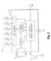
- FIG. 2is a block diagram of a control circuit and an alternate LED arrangement for the display sticker of FIG. 1 .
- FIG. 1shows an exploded rear view of a display sticker 10 according to the present invention.
- a thin flexible sheet 12has a printed circuit board 14 adhesively affixed to its back surface 16 by a layer of adhesive 18 which preferably covers the entire back surface of the flexible sheet.
- the front surface of the stickermay have printed thereon a product or company name, slogan or design, or other advertising indicia or indicia of other types.
- the stickeris preferably provided with a peel-off backing 20 which covers the portion of adhesive layer 18 around the area occupied by the circuit board.
- a second peel-off backing 22may be provided to cover the circuit board area before the circuit board is affixed to the sticker, if desired.
- the stickerpreferably includes a pre-punched hole 24 through the flexible sheet 12 for an LED 26 .
- the front surface of the circuit boardis flat and free of components except for an LED and is affixed to the back surface of sheet 12 in the area exposed after removal of backing 22 . LED 26 protrudes through hole 24 when the circuit board is affixed to sheet 12 .
- a suitable material for flexible sheet 12is 60# white high gloss paper, and a 40# release liner is suitable for backing sheets 20 and 22 .
- Such materialsare commercially available from Brown-Bridge Industries of Troy, Ohio.
- Brown-Bridge B-82 rubber-based, pressure-sensitive adhesiveis suitable for adhesive layer 18 .
- the printed circuit boardmay have a diameter of approximately 1′′, and a maximum height of approximately 1 ⁇ 8′′ which is defined by the height of a battery or batteries 28 .
- the circuit boardhas a diameter of approximately 1.5′′ and a maximum height of approximately ⁇ fraction (3/16) ⁇ ′′.
- the entire circuit boardis small in relation to the height and width of sheet 12 , and is positioned near the center thereof so as to be spaced apart from the periphery thereof. So constructed, the display sticker may be placed on an exposed surface of a shirt, sweater, dress, jacket or other fabric article without producing a noticeable bulge in the fabric surface or the surface of flexible sheet 12 .
- the circuit boardis also sufficiently lightweight as to avoid causing any noticeable sag in the surface of a garment to which it is attached.
- the control circuitmay have one LED as depicted on printed circuit board 14 in FIG. 1, or may have multiple LEDs driven by an LED decoder which is suitably included in a signal generator IC 46 along with a clock, a binary counter and a device control and power management circuit interconnected as shown in the drawing.
- a pushbutton membrane switch 44is provided on the printed circuit board adjacent to the IC to trigger the IC into an active state in which it energizes the LED to flash at a predetermined humanly perceptible rate.
- the circuitis preferably designed to operate at a flashing rate of about 100 msec. or more between flashes.
- the LEDis a high-brightness LED, whereby a flash duration of approximately 3 msec. or less is sufficient to generate enough light to attract attention from a reasonable distance.
- IC 46is preferably a monolithic CMOS integrated circuit with an on-chip capacitor in the clock circuit, and is fabricated according to well known techniques.
- the device control circuitprovides a battery-saving sleep state for the IC.
- the device control circuitis continually supplied with power via the VDD input connected to the battery, but it controllably supplies power to the other circuit blocks, which, like the device control circuit, incorporate CMOS technology. Consequently, the device control circuit enables the IC to draw 1 ⁇ A or less of battery current when the IC is in its dormant or sleep state, during which the supply of power to the clock, counter and decoder is switched off by the device control circuit.
- the device control circuitis suitably a flip-flop which is set in response to a first closure of the membrane switch, whereupon the device control circuit goes into the active state and supplies battery power to all of the circuit blocks of the IC.
- the clockthen begins oscillation at a frequency determined by the RC time constant of the external resistor 48 and the internal on-chip capacitor. This clock frequency then drives the binary counter which, in turn, drives the LED decoder.
- the decoderconverts binary data from the counter into an LED firing signal at a preset duty cycle. If LEDs are connected to more than one output of the decoder, the decoder converts binary data from the counter into a sequential firing of the LED outputs at the same duty cycle.
- the device control flip-flopis reset in response to a second closure of the membrane switch and thereby switches the IC back into the sleep state.
- IC 46is preferably supplied in die form and wire bonded onto the circuit board.
- the circuit board as shown in FIG. 1has a pair of 1.5V alkaline manganese dioxide button cell batteries mounted thereon in series so as to provide a 3V DC source.
- Each battery, and thus the series connection of the two cellspreferably has a capacity of 20-50 mA-hr.
- a 3V lithium manganese dioxide coin cell with 200 mA-hr capacitymay be used.
- the capacity of the power sourcemay be less than 20 mA-hr although it is preferably at least 20 mA-hr.
- commercially available button cellshaving a nominal capacity of 19 mA-hr and 13-14 mA-hr, the latter corresponding to Type AG1, are contemplated as useful in certain desired applications.
- the circuitrymay be mounted on a flexible printed circuit board instead of a rigid circuit board.
- a sound sourcemay be employed as an indicator in place of an LED or other light source.
- a metal dome switchmay be used instead of a membrane switch.
- flexible sheet 12may be made of vinyl, Tyvek®, or other materials suitable for stickers, and is preferably paper-thin, e.g., 0.002-0.006′′ in thickness.
- the paper substrate of the preferred embodimentis 0.004′′ thick. Thicknesses of up to 0.020′′ or so are also contemplated for certain applications.
- the materialmay be clear and in such cases may have printed indicia on the same surface as the printed circuit board instead of the opposite surface as described above.
Landscapes
- Physics & Mathematics (AREA)
- General Physics & Mathematics (AREA)
- Engineering & Computer Science (AREA)
- Theoretical Computer Science (AREA)
- Illuminated Signs And Luminous Advertising (AREA)
Abstract
Description
| Patent No. | Inventor | Issue Date | ||
| 4,164,008 | Miller et al. | Aug. 7, | 1979 | ||
| 4,308,572 | Davidson et al. | Dec. 29, | 1981 | ||
| 4,709,307 | Branom | Nov. 24, | 1987 | ||
| 4,774,434 | Bennion | Sep. 27, | 1988 | ||
| 4,823,240 | Shenker | Apr. 18, | 1989 | ||
| 5,371,657 | Wiscombe | Dec. 6, | 1994 | ||
| 5,440,461 | Nadel et al. | Aug. 8, | 1995 | ||
| 5,455,749 | Ferber | Oct. 3, | 1995 | ||
Claims (18)
Priority Applications (1)
| Application Number | Priority Date | Filing Date | Title |
|---|---|---|---|
| US09/481,312US6420008B1 (en) | 1997-01-28 | 2000-01-11 | Display sticker with integral flasher circuit and power source |
Applications Claiming Priority (2)
| Application Number | Priority Date | Filing Date | Title |
|---|---|---|---|
| US08/789,249US6013346A (en) | 1997-01-28 | 1997-01-28 | Display sticker with integral flasher circuit and power source |
| US09/481,312US6420008B1 (en) | 1997-01-28 | 2000-01-11 | Display sticker with integral flasher circuit and power source |
Related Parent Applications (1)
| Application Number | Title | Priority Date | Filing Date |
|---|---|---|---|
| US08/789,249Continuation-In-PartUS6013346A (en) | 1997-01-28 | 1997-01-28 | Display sticker with integral flasher circuit and power source |
Publications (1)
| Publication Number | Publication Date |
|---|---|
| US6420008B1true US6420008B1 (en) | 2002-07-16 |
Family
ID=46276614
Family Applications (1)
| Application Number | Title | Priority Date | Filing Date |
|---|---|---|---|
| US09/481,312Expired - LifetimeUS6420008B1 (en) | 1997-01-28 | 2000-01-11 | Display sticker with integral flasher circuit and power source |
Country Status (1)
| Country | Link |
|---|---|
| US (1) | US6420008B1 (en) |
Cited By (38)
| Publication number | Priority date | Publication date | Assignee | Title |
|---|---|---|---|---|
| US20040049962A1 (en)* | 2002-09-16 | 2004-03-18 | Masoud Moshirnoroozi | Lighted picture frame |
| US20040224138A1 (en)* | 2000-10-16 | 2004-11-11 | Brian Farrell | Electrically active textile article |
| US20050024858A1 (en)* | 2003-07-14 | 2005-02-03 | Richard Johnson | Container illumination |
| US20060096143A1 (en)* | 2004-11-05 | 2006-05-11 | Egan Kevin J | Temporary, re-positionable, removable framing device |
| US20060139928A1 (en)* | 2003-06-12 | 2006-06-29 | Bryn Griffiths | Container with light or sound generator |
| US7462035B2 (en) | 2005-07-27 | 2008-12-09 | Physical Optics Corporation | Electrical connector configured as a fastening element |
| USD585095S1 (en)* | 2006-09-14 | 2009-01-20 | Glaxo Group Limited | Label |
| US20090100570A1 (en)* | 2007-10-22 | 2009-04-23 | Wei Jei Tuan | Patch for garments and other products for producing light and sound |
| USD592252S1 (en) | 2006-09-14 | 2009-05-12 | Glaxco Group Limited | Label |
| US7559902B2 (en) | 2003-08-22 | 2009-07-14 | Foster-Miller, Inc. | Physiological monitoring garment |
| US20100058511A1 (en)* | 2009-11-13 | 2010-03-11 | Natasha Lee | Apparel having removably supporting communication elements |
| US20100100997A1 (en)* | 2008-10-27 | 2010-04-29 | Lee Kang S | Electrical garment and electrical garment and article assemblies |
| US20100122832A1 (en)* | 2008-11-17 | 2010-05-20 | Leonid Bukshpun | Self-healing electrical communication paths |
| US20100217215A1 (en)* | 2007-06-25 | 2010-08-26 | Mads Lykke | Ostomy appliance with multiple release liners |
| US20100238637A1 (en)* | 2006-06-08 | 2010-09-23 | Koninklijke Philips Electronics N.V. | Submount for electronic components |
| US20100263247A1 (en)* | 2009-04-21 | 2010-10-21 | Liguori Thomas A | Forehead adhesive display |
| US7927253B2 (en) | 2007-08-17 | 2011-04-19 | Adidas International Marketing B.V. | Sports electronic training system with electronic gaming features, and applications thereof |
| USD637750S1 (en) | 2008-09-08 | 2011-05-10 | Benmore Ventures Ltd | Light-emitting unit for bottles and other containers |
| US20110188237A1 (en)* | 2008-09-01 | 2011-08-04 | Bryn Griffiths | Container illumination device |
| US20120176789A1 (en)* | 2009-09-30 | 2012-07-12 | Koninklijke Philips Electronics N.V. | Light output sticker |
| US8247678B1 (en)* | 2009-05-13 | 2012-08-21 | Steven T. Ivy | Membranophone tuning system having positionable magnets |
| USD668802S1 (en) | 2010-10-07 | 2012-10-09 | Finch Ronald V | Bicycle light |
| US8360904B2 (en) | 2007-08-17 | 2013-01-29 | Adidas International Marketing Bv | Sports electronic training system with sport ball, and applications thereof |
| US20130193646A1 (en)* | 2012-01-27 | 2013-08-01 | Wei Su | Affixable firearms target capable of leaving a custom-shaped silhouette visible from afar upon the projectile's impact on the target's bullseye |
| US8585606B2 (en) | 2010-09-23 | 2013-11-19 | QinetiQ North America, Inc. | Physiological status monitoring system |
| US8702430B2 (en) | 2007-08-17 | 2014-04-22 | Adidas International Marketing B.V. | Sports electronic training system, and applications thereof |
| US20140146537A1 (en)* | 2012-11-24 | 2014-05-29 | Ronald Dominick Crognale | Customizable decorative party apparatus |
| US9028404B2 (en) | 2010-07-28 | 2015-05-12 | Foster-Miller, Inc. | Physiological status monitoring system |
| US9086194B2 (en) | 2010-12-23 | 2015-07-21 | 3M Innovative Properties Company | Clip light |
| US9211085B2 (en) | 2010-05-03 | 2015-12-15 | Foster-Miller, Inc. | Respiration sensing system |
| USD749071S1 (en)* | 2014-05-15 | 2016-02-09 | Nick Moore | Control interface shield |
| US9326895B1 (en)* | 2005-02-10 | 2016-05-03 | James M. Winey | Protective napkin |
| US20170363259A1 (en)* | 2016-06-20 | 2017-12-21 | Xia Feng | Light Emitting Device For A Container |
| DE202016106373U1 (en)* | 2016-11-14 | 2018-02-15 | königlich feiern GmbH | Illumination device for illuminating a container |
| USD832127S1 (en)* | 2016-06-25 | 2018-10-30 | Dan Grois | Combined display apparatus and pendant |
| USD832129S1 (en)* | 2016-06-25 | 2018-10-30 | Dan Grois | Combined display apparatus and pendant |
| USD832733S1 (en)* | 2016-06-25 | 2018-11-06 | Dan Grois | Combined display apparatus and pendant |
| US10925358B1 (en)* | 2020-05-14 | 2021-02-23 | Amanda Shawhan | Artificial jewel with internal light source for skin body art |
Citations (21)
| Publication number | Priority date | Publication date | Assignee | Title |
|---|---|---|---|---|
| US4164008A (en) | 1977-02-24 | 1979-08-07 | Stanley M. Meyer | Illuminated article of clothing |
| US4215388A (en) | 1978-11-09 | 1980-07-29 | Reimann Roman M | Novelty button |
| US4308572A (en) | 1977-06-20 | 1981-12-29 | Sidney Davidson | Articles having light-emitting elements energizable in sequences to provide desired visual displays |
| US4367515A (en) | 1980-10-29 | 1983-01-04 | Beard Steven F | Roller skate light attachment |
| US4709307A (en) | 1986-06-20 | 1987-11-24 | Mcknight Road Enterprises, Inc. | Clothing with illuminated display |
| US4774434A (en) | 1986-08-13 | 1988-09-27 | Innovative Products, Inc. | Lighted display including led's mounted on a flexible circuit board |
| US4823240A (en) | 1987-09-01 | 1989-04-18 | Nathan Shenker | Audio-visual assembly for articles of clothing |
| CH669893A5 (en) | 1986-11-07 | 1989-04-28 | Rene Zurkinden | Luminous badge for wearing on shirt or jacket - uses battery to power lamp which illuminates screen over which translucent labels may be fitted as name tags |
| US4962602A (en) | 1986-10-03 | 1990-10-16 | Meyrowitsch Ralph S | Sticker for alarm system |
| US5113325A (en) | 1991-08-01 | 1992-05-12 | Eisenbraun Kenneth D | Light assembly kit for illuminating an article of clothing |
| US5193895A (en) | 1990-01-18 | 1993-03-16 | Koito Manufacturing Co., Ltd. | Warning light |
| US5336977A (en) | 1993-05-18 | 1994-08-09 | Li Ming Chun | Emergency lighting device |
| US5371657A (en) | 1993-09-13 | 1994-12-06 | Tenco Partnership | Pliable illuminated fabric articles |
| US5375044A (en) | 1991-05-13 | 1994-12-20 | Guritz; Steven P. W. | Multipurpose optical display for articulating surfaces |
| US5434759A (en) | 1992-10-20 | 1995-07-18 | Endo; Osamu | Safety indicating device |
| US5440461A (en) | 1994-05-02 | 1995-08-08 | Nadel; Craig P. | Light illuminating assemblies for wearing apparel with light element securement means |
| US5455749A (en) | 1993-05-28 | 1995-10-03 | Ferber; Andrew R. | Light, audio and current related assemblies, attachments and devices with conductive compositions |
| US5497140A (en) | 1992-08-12 | 1996-03-05 | Micron Technology, Inc. | Electrically powered postage stamp or mailing or shipping label operative with radio frequency (RF) communication |
| US5531601A (en) | 1995-06-23 | 1996-07-02 | Amoroso; Eugene C. | Fabric battery pouch |
| US5566384A (en) | 1994-05-23 | 1996-10-15 | Chien; Tseng-Lu | Vehicle with an EL light strip |
| US6013346A (en)* | 1997-01-28 | 2000-01-11 | Buztronics, Inc. | Display sticker with integral flasher circuit and power source |
- 2000
- 2000-01-11USUS09/481,312patent/US6420008B1/ennot_activeExpired - Lifetime
Patent Citations (22)
| Publication number | Priority date | Publication date | Assignee | Title |
|---|---|---|---|---|
| US4164008A (en) | 1977-02-24 | 1979-08-07 | Stanley M. Meyer | Illuminated article of clothing |
| US4308572A (en) | 1977-06-20 | 1981-12-29 | Sidney Davidson | Articles having light-emitting elements energizable in sequences to provide desired visual displays |
| US4215388A (en) | 1978-11-09 | 1980-07-29 | Reimann Roman M | Novelty button |
| US4367515A (en) | 1980-10-29 | 1983-01-04 | Beard Steven F | Roller skate light attachment |
| US4709307A (en) | 1986-06-20 | 1987-11-24 | Mcknight Road Enterprises, Inc. | Clothing with illuminated display |
| US4774434A (en) | 1986-08-13 | 1988-09-27 | Innovative Products, Inc. | Lighted display including led's mounted on a flexible circuit board |
| US4962602A (en) | 1986-10-03 | 1990-10-16 | Meyrowitsch Ralph S | Sticker for alarm system |
| CH669893A5 (en) | 1986-11-07 | 1989-04-28 | Rene Zurkinden | Luminous badge for wearing on shirt or jacket - uses battery to power lamp which illuminates screen over which translucent labels may be fitted as name tags |
| US4823240A (en) | 1987-09-01 | 1989-04-18 | Nathan Shenker | Audio-visual assembly for articles of clothing |
| US5193895A (en) | 1990-01-18 | 1993-03-16 | Koito Manufacturing Co., Ltd. | Warning light |
| US5375044A (en) | 1991-05-13 | 1994-12-20 | Guritz; Steven P. W. | Multipurpose optical display for articulating surfaces |
| US5113325A (en) | 1991-08-01 | 1992-05-12 | Eisenbraun Kenneth D | Light assembly kit for illuminating an article of clothing |
| US5113325B1 (en) | 1991-08-01 | 1994-09-13 | Eisenbraun Reiss Inc | Light assembly kit for illuminating an article of clothing |
| US5497140A (en) | 1992-08-12 | 1996-03-05 | Micron Technology, Inc. | Electrically powered postage stamp or mailing or shipping label operative with radio frequency (RF) communication |
| US5434759A (en) | 1992-10-20 | 1995-07-18 | Endo; Osamu | Safety indicating device |
| US5336977A (en) | 1993-05-18 | 1994-08-09 | Li Ming Chun | Emergency lighting device |
| US5455749A (en) | 1993-05-28 | 1995-10-03 | Ferber; Andrew R. | Light, audio and current related assemblies, attachments and devices with conductive compositions |
| US5371657A (en) | 1993-09-13 | 1994-12-06 | Tenco Partnership | Pliable illuminated fabric articles |
| US5440461A (en) | 1994-05-02 | 1995-08-08 | Nadel; Craig P. | Light illuminating assemblies for wearing apparel with light element securement means |
| US5566384A (en) | 1994-05-23 | 1996-10-15 | Chien; Tseng-Lu | Vehicle with an EL light strip |
| US5531601A (en) | 1995-06-23 | 1996-07-02 | Amoroso; Eugene C. | Fabric battery pouch |
| US6013346A (en)* | 1997-01-28 | 2000-01-11 | Buztronics, Inc. | Display sticker with integral flasher circuit and power source |
Non-Patent Citations (2)
| Title |
|---|
| Product literature, Buztronics New Product Flashing Action Stickers "Just Peel & Stick Em", 1 page, copyright 1997. |
| The Power Within, Product Selector catalog, Energizer Power Systems, 6 pages, Oct. 1995. |
Cited By (64)
| Publication number | Priority date | Publication date | Assignee | Title |
|---|---|---|---|---|
| US20040224138A1 (en)* | 2000-10-16 | 2004-11-11 | Brian Farrell | Electrically active textile article |
| US20040049962A1 (en)* | 2002-09-16 | 2004-03-18 | Masoud Moshirnoroozi | Lighted picture frame |
| US20060139928A1 (en)* | 2003-06-12 | 2006-06-29 | Bryn Griffiths | Container with light or sound generator |
| US20050024858A1 (en)* | 2003-07-14 | 2005-02-03 | Richard Johnson | Container illumination |
| US7559902B2 (en) | 2003-08-22 | 2009-07-14 | Foster-Miller, Inc. | Physiological monitoring garment |
| US20060096143A1 (en)* | 2004-11-05 | 2006-05-11 | Egan Kevin J | Temporary, re-positionable, removable framing device |
| US9326895B1 (en)* | 2005-02-10 | 2016-05-03 | James M. Winey | Protective napkin |
| US20090117753A1 (en)* | 2005-07-27 | 2009-05-07 | Kang Lee | Body conformable electrical network |
| US7731517B2 (en) | 2005-07-27 | 2010-06-08 | Physical Optics Corporation | Inherently sealed electrical connector |
| US20090149037A1 (en)* | 2005-07-27 | 2009-06-11 | Kang Lee | Self-identifying electrical connector |
| US20090149036A1 (en)* | 2005-07-27 | 2009-06-11 | Kang Lee | Inherently sealed electrical connector |
| US7556532B2 (en) | 2005-07-27 | 2009-07-07 | Physical Optics Corporation | Electrical connector configured as a fastening element |
| US7462035B2 (en) | 2005-07-27 | 2008-12-09 | Physical Optics Corporation | Electrical connector configured as a fastening element |
| US7658612B2 (en) | 2005-07-27 | 2010-02-09 | Physical Optics Corporation | Body conformable electrical network |
| US7753685B2 (en) | 2005-07-27 | 2010-07-13 | Physical Optics Corporation | Self-identifying electrical connector |
| US8259460B2 (en) | 2006-06-08 | 2012-09-04 | Koninklijke Philips Electronics N.V. | Submount for electronic components |
| US20100238637A1 (en)* | 2006-06-08 | 2010-09-23 | Koninklijke Philips Electronics N.V. | Submount for electronic components |
| USD592252S1 (en) | 2006-09-14 | 2009-05-12 | Glaxco Group Limited | Label |
| USD585095S1 (en)* | 2006-09-14 | 2009-01-20 | Glaxo Group Limited | Label |
| US9452079B2 (en) | 2007-06-25 | 2016-09-27 | Coloplast A/S | Ostomy appliance wafer with liner system |
| US9233019B2 (en)* | 2007-06-25 | 2016-01-12 | Coloplast A/S | Ostomy appliance with multiple release liners |
| US20100217215A1 (en)* | 2007-06-25 | 2010-08-26 | Mads Lykke | Ostomy appliance with multiple release liners |
| US8221290B2 (en) | 2007-08-17 | 2012-07-17 | Adidas International Marketing B.V. | Sports electronic training system with electronic gaming features, and applications thereof |
| US12020588B2 (en) | 2007-08-17 | 2024-06-25 | Adidas International Marketing B.V. | Sports electronic training system, and applications thereof |
| US8702430B2 (en) | 2007-08-17 | 2014-04-22 | Adidas International Marketing B.V. | Sports electronic training system, and applications thereof |
| US9087159B2 (en) | 2007-08-17 | 2015-07-21 | Adidas International Marketing B.V. | Sports electronic training system with sport ball, and applications thereof |
| US9625485B2 (en) | 2007-08-17 | 2017-04-18 | Adidas International Marketing B.V. | Sports electronic training system, and applications thereof |
| US9645165B2 (en) | 2007-08-17 | 2017-05-09 | Adidas International Marketing B.V. | Sports electronic training system with sport ball, and applications thereof |
| US9759738B2 (en) | 2007-08-17 | 2017-09-12 | Adidas International Marketing B.V. | Sports electronic training system, and applications thereof |
| US10062297B2 (en) | 2007-08-17 | 2018-08-28 | Adidas International Marketing B.V. | Sports electronic training system, and applications thereof |
| US8360904B2 (en) | 2007-08-17 | 2013-01-29 | Adidas International Marketing Bv | Sports electronic training system with sport ball, and applications thereof |
| US9242142B2 (en) | 2007-08-17 | 2016-01-26 | Adidas International Marketing B.V. | Sports electronic training system with sport ball and electronic gaming features |
| US7927253B2 (en) | 2007-08-17 | 2011-04-19 | Adidas International Marketing B.V. | Sports electronic training system with electronic gaming features, and applications thereof |
| US20090100570A1 (en)* | 2007-10-22 | 2009-04-23 | Wei Jei Tuan | Patch for garments and other products for producing light and sound |
| US8814379B2 (en) | 2008-09-01 | 2014-08-26 | Benmore Ventures Ltd. | Container illumination device |
| EP2323912B2 (en)† | 2008-09-01 | 2015-08-19 | Benmore Ventures Limited | Container illumination device and method for its manufacturing |
| US20110188237A1 (en)* | 2008-09-01 | 2011-08-04 | Bryn Griffiths | Container illumination device |
| USD637750S1 (en) | 2008-09-08 | 2011-05-10 | Benmore Ventures Ltd | Light-emitting unit for bottles and other containers |
| US8308489B2 (en) | 2008-10-27 | 2012-11-13 | Physical Optics Corporation | Electrical garment and electrical garment and article assemblies |
| US20100100997A1 (en)* | 2008-10-27 | 2010-04-29 | Lee Kang S | Electrical garment and electrical garment and article assemblies |
| US8063307B2 (en) | 2008-11-17 | 2011-11-22 | Physical Optics Corporation | Self-healing electrical communication paths |
| US20100122832A1 (en)* | 2008-11-17 | 2010-05-20 | Leonid Bukshpun | Self-healing electrical communication paths |
| US20100263247A1 (en)* | 2009-04-21 | 2010-10-21 | Liguori Thomas A | Forehead adhesive display |
| US8247678B1 (en)* | 2009-05-13 | 2012-08-21 | Steven T. Ivy | Membranophone tuning system having positionable magnets |
| US20120176789A1 (en)* | 2009-09-30 | 2012-07-12 | Koninklijke Philips Electronics N.V. | Light output sticker |
| US20100058511A1 (en)* | 2009-11-13 | 2010-03-11 | Natasha Lee | Apparel having removably supporting communication elements |
| US9211085B2 (en) | 2010-05-03 | 2015-12-15 | Foster-Miller, Inc. | Respiration sensing system |
| US9028404B2 (en) | 2010-07-28 | 2015-05-12 | Foster-Miller, Inc. | Physiological status monitoring system |
| US8585606B2 (en) | 2010-09-23 | 2013-11-19 | QinetiQ North America, Inc. | Physiological status monitoring system |
| USD668802S1 (en) | 2010-10-07 | 2012-10-09 | Finch Ronald V | Bicycle light |
| US9086194B2 (en) | 2010-12-23 | 2015-07-21 | 3M Innovative Properties Company | Clip light |
| US20130193646A1 (en)* | 2012-01-27 | 2013-08-01 | Wei Su | Affixable firearms target capable of leaving a custom-shaped silhouette visible from afar upon the projectile's impact on the target's bullseye |
| US8556268B2 (en)* | 2012-01-27 | 2013-10-15 | Wei Su | Affixable firearms target capable of leaving a custom-shaped silhouette visible from afar upon the projectile's impact on the target's bullseye |
| US20140146537A1 (en)* | 2012-11-24 | 2014-05-29 | Ronald Dominick Crognale | Customizable decorative party apparatus |
| US8998451B2 (en)* | 2012-11-24 | 2015-04-07 | Ronald Dominick Crognale | Customizable decorative party apparatus |
| USD749071S1 (en)* | 2014-05-15 | 2016-02-09 | Nick Moore | Control interface shield |
| US20170363259A1 (en)* | 2016-06-20 | 2017-12-21 | Xia Feng | Light Emitting Device For A Container |
| US10359160B2 (en)* | 2016-06-20 | 2019-07-23 | Xia Feng | Light emitting device for a container |
| USD832127S1 (en)* | 2016-06-25 | 2018-10-30 | Dan Grois | Combined display apparatus and pendant |
| USD832129S1 (en)* | 2016-06-25 | 2018-10-30 | Dan Grois | Combined display apparatus and pendant |
| USD832733S1 (en)* | 2016-06-25 | 2018-11-06 | Dan Grois | Combined display apparatus and pendant |
| WO2018087373A1 (en)* | 2016-11-14 | 2018-05-17 | königlich feiern GmbH | Illumination device for illuminating a container |
| DE202016106373U1 (en)* | 2016-11-14 | 2018-02-15 | königlich feiern GmbH | Illumination device for illuminating a container |
| US10925358B1 (en)* | 2020-05-14 | 2021-02-23 | Amanda Shawhan | Artificial jewel with internal light source for skin body art |
Similar Documents
| Publication | Publication Date | Title |
|---|---|---|
| US6420008B1 (en) | Display sticker with integral flasher circuit and power source | |
| US6013346A (en) | Display sticker with integral flasher circuit and power source | |
| US7065909B2 (en) | Portable animated illuminated panel display device | |
| US4531310A (en) | Display element | |
| US6197396B1 (en) | Identification card strip assembly | |
| CA2368130A1 (en) | Programmable electronic label | |
| US7182217B2 (en) | Sheet dispensers and methods of making and using the same | |
| JP2008516264A (en) | Substrate with light display | |
| US4862436A (en) | Watch with strap | |
| CA2311203A1 (en) | Rfid or eas label mount with double sided tape | |
| US20020076518A1 (en) | Light-reflectable sticker | |
| DE60014428D1 (en) | COMPUTER CONTROLLED IDENTIFICATION GENERATION SYSTEM | |
| US5755506A (en) | Illuminated badge | |
| WO2000067240A3 (en) | Electronic tags incorporating a customer attracting annunciator for use in electronic product information display systems | |
| US20030121191A1 (en) | Customizable back lighted sign | |
| US20020085375A1 (en) | Vibration-activated light emitting indication apparatus | |
| US20030196358A1 (en) | Pizza advertizing and delivery beacon | |
| JPH09244535A (en) | Voice label | |
| KR0163941B1 (en) | Sticker with electronic sound and indication | |
| DE50002134D1 (en) | Nameplate Case | |
| JP3104391U (en) | Adhesive digital LCD watch | |
| JP3031671U (en) | Small flashing light emitting unit | |
| KR200383981Y1 (en) | Magnetic mirror | |
| JP3075717U (en) | Mounting structure of advertising plate in vending machine | |
| GB2386460A (en) | Portable illuminated sign |
Legal Events
| Date | Code | Title | Description |
|---|---|---|---|
| AS | Assignment | Owner name:BUZTRONICS, INC., INDIANA Free format text:ASSIGNMENT OF ASSIGNORS INTEREST;ASSIGNORS:LEWIS, EDWARD D.;LEUNG, RAYMOND W.;REEL/FRAME:011298/0018;SIGNING DATES FROM 20000908 TO 20000913 | |
| STCF | Information on status: patent grant | Free format text:PATENTED CASE | |
| FPAY | Fee payment | Year of fee payment:4 | |
| AS | Assignment | Owner name:FIRST BUSINESS CAPITAL CORP., WISCONSIN Free format text:ASSIGNMENT OF ASSIGNORS INTEREST;ASSIGNOR:BUZTRONICS, INC.;REEL/FRAME:019597/0778 Effective date:20070628 | |
| FPAY | Fee payment | Year of fee payment:8 | |
| AS | Assignment | Owner name:BUZTRONICS, INC., INDIANA Free format text:ASSIGNMENT OF ASSIGNORS INTEREST;ASSIGNOR:FIRST BUSINESS CAPITAL CORP.;REEL/FRAME:027633/0033 Effective date:20111101 | |
| REMI | Maintenance fee reminder mailed | ||
| FPAY | Fee payment | Year of fee payment:12 | |
| SULP | Surcharge for late payment | Year of fee payment:11 | |
| AS | Assignment | Owner name:LEWIS, EDWARD D., INDIANA Free format text:ASSIGNMENT OF ASSIGNORS INTEREST;ASSIGNOR:BUZTRONICS, INC.;REEL/FRAME:038895/0897 Effective date:20160608 |