US6419608B1 - Continuously variable transmission - Google Patents
Continuously variable transmissionDownload PDFInfo
- Publication number
- US6419608B1 US6419608B1US09/695,757US69575700AUS6419608B1US 6419608 B1US6419608 B1US 6419608B1US 69575700 AUS69575700 AUS 69575700AUS 6419608 B1US6419608 B1US 6419608B1
- Authority
- US
- United States
- Prior art keywords
- transmission
- driving member
- rotating
- power adjusters
- additionally
- Prior art date
- Legal status (The legal status is an assumption and is not a legal conclusion. Google has not performed a legal analysis and makes no representation as to the accuracy of the status listed.)
- Expired - Lifetime
Links
Images


Classifications
- B—PERFORMING OPERATIONS; TRANSPORTING
- B62—LAND VEHICLES FOR TRAVELLING OTHERWISE THAN ON RAILS
- B62M—RIDER PROPULSION OF WHEELED VEHICLES OR SLEDGES; POWERED PROPULSION OF SLEDGES OR SINGLE-TRACK CYCLES; TRANSMISSIONS SPECIALLY ADAPTED FOR SUCH VEHICLES
- B62M9/00—Transmissions characterised by use of an endless chain, belt, or the like
- B62M9/04—Transmissions characterised by use of an endless chain, belt, or the like of changeable ratio
- B62M9/06—Transmissions characterised by use of an endless chain, belt, or the like of changeable ratio using a single chain, belt, or the like
- B62M9/08—Transmissions characterised by use of an endless chain, belt, or the like of changeable ratio using a single chain, belt, or the like involving eccentrically- mounted or elliptically-shaped driving or driven wheel; with expansible driving or driven wheel
- F—MECHANICAL ENGINEERING; LIGHTING; HEATING; WEAPONS; BLASTING
- F16—ENGINEERING ELEMENTS AND UNITS; GENERAL MEASURES FOR PRODUCING AND MAINTAINING EFFECTIVE FUNCTIONING OF MACHINES OR INSTALLATIONS; THERMAL INSULATION IN GENERAL
- F16H—GEARING
- F16H15/00—Gearings for conveying rotary motion with variable gear ratio, or for reversing rotary motion, by friction between rotary members
- F16H15/02—Gearings for conveying rotary motion with variable gear ratio, or for reversing rotary motion, by friction between rotary members without members having orbital motion
- F16H15/04—Gearings providing a continuous range of gear ratios
- F16H15/06—Gearings providing a continuous range of gear ratios in which a member A of uniform effective diameter mounted on a shaft may co-operate with different parts of a member B
- F16H15/26—Gearings providing a continuous range of gear ratios in which a member A of uniform effective diameter mounted on a shaft may co-operate with different parts of a member B in which the member B has a spherical friction surface centered on its axis of revolution
- F16H15/28—Gearings providing a continuous range of gear ratios in which a member A of uniform effective diameter mounted on a shaft may co-operate with different parts of a member B in which the member B has a spherical friction surface centered on its axis of revolution with external friction surface
- F—MECHANICAL ENGINEERING; LIGHTING; HEATING; WEAPONS; BLASTING
- F16—ENGINEERING ELEMENTS AND UNITS; GENERAL MEASURES FOR PRODUCING AND MAINTAINING EFFECTIVE FUNCTIONING OF MACHINES OR INSTALLATIONS; THERMAL INSULATION IN GENERAL
- F16H—GEARING
- F16H61/00—Control functions within control units of change-speed- or reversing-gearings for conveying rotary motion ; Control of exclusively fluid gearing, friction gearing, gearings with endless flexible members or other particular types of gearing
- F16H61/66—Control functions within control units of change-speed- or reversing-gearings for conveying rotary motion ; Control of exclusively fluid gearing, friction gearing, gearings with endless flexible members or other particular types of gearing specially adapted for continuously variable gearings
- F16H61/664—Friction gearings
Definitions
- the field of the inventionrelates to transmissions. More particularly the invention relates to continuously variable transmissions.
- Yet another limitation of this designis that it requires the use of two half axles, one on each side of the rollers, to provide a gap in the middle of the two half axles. The gap is necessary because the rollers are shifted with rotating motion instead of sliding linear motion.
- the use of two axlesis not desirable and requires a complex fastening system to prevent the axles from bending when the transmission is accidentally bumped, is as often the case when a transmission is employed in a vehicle.
- Yet another limitation of this designis that it does not provide for an automatic transmission.
- the present inventionincludes a transmission for use in rotationally or linearly powered machines and vehicles.
- the present transmissionmay be used in machines such as drill presses, turbines, and food processing equipment, and vehicles such as automobiles, motorcycles, and bicycles.
- the transmissionmay, for example, be driven by a power transfer mechanism such as a sprocket, gear, pulley or lever, optionally driving a one way clutch attached at one end of the main shaft.
- the transmissioncomprises a rotatable driving member, three or more power adjusters, wherein each of the power adjusters respectively rotates about an axis of rotation that is centrally located within each of the power adjusters, a support member providing a support surface that is in frictional contact with each of the power adjusters, wherein the support member rotates about an axis that is centrally located within the support member, at least one platform for actuating axial movement of the support member and for actuating a shift in the axis of rotation of the power adjusters, wherein the platform provides a convex surface, at least one stationary support that is non-rotatable about the axis of rotation that is defined by the support member, wherein the at least one stationary support provides a concave surface, and a plurality of spindle supports, wherein each of the spindle supports are slidingly engaged with the convex surface of the platform and the concave surface of the stationary support, and wherein each of the spindle supports adjusts the axes of rotation
- the transmissioncomprises a rotatable driving member; three or more power adjusters, wherein each of the power adjusters respectively rotates about an axis of rotation that is respectively central to the power adjusters, a support member providing a support surface that is in frictional contact with each of the power adjusters, a rotatable driving member for rotating each of the power adjusters, a bearing disc having a plurality of inclined ramps for actuating the rotation of the driving member, a coiled spring for biasing the rotatable driving member against the power adjusters, at least one lock pawl ratchet, wherein the lock pawl ratchet is rigidly attached to the rotatable driving member, wherein the at least one lock pawl is operably attached to the coiled spring, and at least one lock pawl for locking the lock pawl ratchet in response to the rotatable driving member becoming disengaged from the power adjusters.
- the transmissioncomprises a rotatable driving member, three or more power adjusters, wherein each of the power adjusters respectively rotates about an axis that is respectively central to each of the power adjusters, a support member providing a support surface that is in frictional contact with each of the power adjusters, wherein the support member rotates about an axis that is centrally located within the support member, a bearing disc having a plurality of inclined ramps for actuating the rotation of the driving member, a screw that is coaxially and rigidly attached to the rotatable driving member or the bearing disc, and a nut that, if the screw is attached to the rotatable driving member, is coaxially and rigidly attached to the bearing disc, or if the screw is rigidly attached to the bearing disc, coaxially and rigidly attached to the rotatable driving member, wherein the inclined ramps of the bearing disc have a higher lead than the screw.
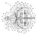
- FIG. 1is a cutaway side view of the transmission of the present invention.
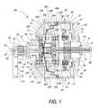
- FIG. 2is a partial perspective view of the transmission of FIG. 1 .
- FIG. 3is a perspective view of two stationary supports of the transmission of FIG. 1 .
- FIG. 4is a partial end, cross-sectional view of the transmission of FIG. 1 .
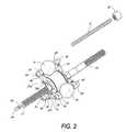
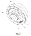
- FIG. 5is a perspective view of a drive disc, bearing cage, screw, and ramp bearings of the transmission of FIG. 1 .
- FIG. 6is a perspective view of a ratchet and pawl subsystem of the transmission of FIG. 1 that is used to engage and disengage the transmission.
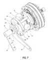
- FIG. 7is partial perspective view of the transmission of FIG. 1, wherein, among other things, a rotatable drive disk has been removed.
- FIG. 8is a partial perspective view of the transmission of FIG. 1, wherein, among other things, the hub shell has been removed.
- FIG. 9is a partial perspective view of the transmission of FIG. 1, wherein the shifting is done automatically.
- FIG. 10is a perspective view of the shifting handlegrip that is mechanically coupled to the transmission of FIG. 1 .
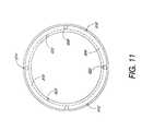
- FIG. 11is an end view of a thrust bearing, of the transmission shown in FIG. 1, which is used for automatic shifting of the transmission.
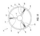
- FIG. 12is an end view of the weight design of the transmission shown in FIG. 1 .
- FIG. 13is a perspective view of an alternate embodiment of the transmission bolted to a flat surface.
- FIG. 14is a cutaway side view of the transmission shown in FIG. 13 .
- FIG. 15is a schematic end view of the transmission in FIG. 1 showing the cable routing across a spacer extension of the automatic portion of the transmission.
- FIG. 16is a schematic end view of the cable routing of the transmission shown in FIG. 13 .
- the present inventionincludes a continuously variable transmission that may be employed in connection with any type of machine that is in need of a transmission.
- the transmissionmay be used in (i) a motorized vehicle such as an automobile, motorcycle, or watercraft, (ii) a non-motorized vehicle such as a bicycle, tricycle, scooter, exercise equipment or (iii) industrial equipment, such as a drill press, power generating equipment, or textile mill.
- a continuously variable transmission 100is disclosed.
- the transmission 100is shrouded in a hub shell 40 covered by a hub cap 67 .
- At the heart of the transmission 100are three or more power adjusters 1 a, 1 b, 1 c which are spherical in shape and are circumferentially spaced equally around the centerline or axis of rotation of the transmission 100 .
- spindles 3 a, 3 b, 3 care inserted through the center of the power adjusters 1 a, 1 b, 1 c to define an axis of rotation for the power adjusters 1 a, 1 b, 1 c.
- the power adjuster's axis of rotationis shown in the horizontal direction.
- Spindle supports 2 a-fare attached perpendicular to and at the exposed ends of the spindles 3 a, 3 b, 3 c.
- each of the spindles supportshave a bore to receive one end of one of the spindles 3 a, 3 b, 3 c.
- the spindles 3 a, 3 b, 3 calso have spindle rollers 4 a-f coaxially and slidingly positioned over the exposed ends of the spindles 3 a, 3 b, 3 c outside of the spindle supports 2 a-f.
- each spindle roller 4 a-ffollows in a groove 6 a-f cut into a stationary support 5 a, 5 b.
- the stationary supports 5 a, 5 bare generally in the form of parallel disks with an axis of rotation along the centerline of the transmission 100 .
- the grooves 6 a-fextend from the outer circumference of the stationary supports 5 a, 5 b towards the centerline of the transmission 100 .
- each pair of spindle rollers 4 a-flocated on a single spindle 3 a, 3 b, 3 c, moves in opposite directions along their corresponding grooves 6 a-f.
- a centerline hole 7 a, 7 b in the stationary supports 5 a, 5 ballows the insertion of a hollow shaft 10 through both stationary supports 5 a, 5 b.
- one or more of the stationary support holes 7 a, 7 bmay have a non-cylindrical shape 14 , which fits over a corresponding non-cylindrical shape 15 along the hollow shaft 10 to prevent any relative rotation between the stationary supports 5 a, 5 b and the hollow shaft 10 . If the rigidity of the stationary supports 5 a, 5 b is insufficient, additional structure may be used to minimize any relative rotational movement or flexing of the stationary supports 5 a, 5 b. This type of movement by the stationary supports 5 a, 5 b may cause binding of the spindle rollers 4 a-f as they move along the grooves 6 a-f.
- the additional structuremay take the form of spacers 8 a, 8 b, 8 c attached between the stationary supports 5 a, 5 b.
- the spacers 8 a, 8 b, 8 cadd rigidity between the stationary supports 5 a, 5 b and, in one embodiment, are located near the outer circumference of the stationary supports 5 a, 5 b.
- the stationary supports 5 a, 5 bare connected to the spacers 8 a, 8 b, 8 c by bolts or other fastener devices 45 a-f inserted through holes 46 a-f in the stationary supports 5 a, 5 b.
- the stationary support 5 ais fixedly attached to a stationary support sleeve 42 , which coaxially encloses the hollow shaft 10 and extends through the wall of the hub shell 40 .
- the end of the stationary support sleeve 42 that extends through the hub shell 40attaches to the frame support and preferentially has a non-cylindrical shape to enhance subsequent attachment of a torque lever 43 .
- the torque lever 43is placed over the non-cylindrical shaped end of the stationary support sleeve 42 , and is held in place by a torque nut 44 .
- the torque lever 43 at its other endis rigidly attached to a strong, non-moving part, such as a frame (not shown).
- a stationary support bearing 48supports the hub shell 40 and permits the hub shell 40 to rotate relative to the stationary support sleeve 42 .
- shiftingis manually activated by axially sliding a rod 11 positioned in the hollow shaft 10 .
- One or more pins 12are inserted through one or more transverse holes in the rod 11 and further extend through one or more longitudinal slots 16 (not shown) in the hollow shaft 10 .
- the slots 16 in the hollow shaft 10allow for axial movement of the pin 12 and rod 11 assembly in the hollow shaft 10 .
- the ends of the transverse pins 12extend into and couple with a coaxial sleeve 19 .
- the sleeve 19is fixedly attached at each end to a substantially planar platform 13 a, 13 b forming a trough around the circumference of the sleeve 19 .
- the planar platforms 13 a, 13 beach contact and push multiple wheels 21 a-f.
- the wheels 21 a-ffit into slots in the spindle supports 2 a-f and are held in place by wheel axles 22 a-f.
- the wheel axles 22 a-fare supported at their ends by the spindle supports 2 a-f and allow rotational movement of the wheels 21 a-f.
- the substantially planar platforms 13 a, 13 btransition into a convex surface at their outer perimeter (farthest from the hollow shaft 10 ). This region allows slack to be taken up when the spindle supports 2 a-f and power adjusters 1 a, 1 b, 1 c are tilted as the transmission 100 is shifted.
- a cylindrical support member 18is located in the trough formed between the planar platforms 13 a, 13 b and sleeve 19 and thus moves in concert with the planar platforms 13 a, 13 b and sleeve 19 .
- the support member 18rides on contact bearings 17 a, 17 b located at the intersection of the planar platforms 13 a, 13 b and sleeve 19 to allow the support member 18 to freely rotate about the axis of the transmission 100 .
- the bearings 17 a, 17 b, support member 18 , and sleeve 19all slide axially with the planar platforms 13 a, 13 b when the transmission 100 is shifted.
- stationary support rollers 30 a-lare attached in pairs to each spindle leg 2 a-f through a roller pin 31 a-f and held in place by roller clips 32 a-l.
- the roller pins 31 a-fallow the stationary support rollers 30 a-l to rotate freely about the roller pins 31 a-f.
- the stationary support rollers 30 a-lroll on a concave radius in the stationary support 5 a, 5 b along a substantially parallel path with the grooves 6 a-f.
- the stationary support rollers 30 a-ldo not allow the ends of the spindles 3 a, 3 b, 3 c nor the spindle rollers 4 a-f to contact the bottom surface of the grooves 6 a-f, to maintain the position of the spindles 3 a, 3 b, 3 c, and to minimize any frictional losses.
- FIG. 4shows the stationary support rollers 30 a-l, the roller pins, 31 a-f, and roller clips 32 a-l, as seen through the stationary support 5 a, for ease of viewing.
- the stationary support rollers 30 a-l, the roller pins, 31 a-f, and roller clips 32 a-lare not numbered in FIG. 1 .
- a concave drive disc 34located adjacent to the stationary support 5 b, partially encapsulates but does not contact the stationary support 5 b.
- the drive disk 34is rigidly attached through its center to a screw 35 .
- the screw 35is coaxial to and forms a sleeve around the hollow shaft 10 adjacent to the stationary support 5 b and faces a driving member 69 .
- the drive disc 34is rotatively coupled to the power adjusters 1 a, 1 b, 1 c along a circumferential bearing surface on the lip of the drive disk 34 .
- a nut 37is threaded over the screw 35 and is rigidly attached around its circumference to a bearing disc 60 .
- One face of the nut 37is further attached to the driving member 69 .
- a plurality of ramps 61which face the drive disc 34 .
- the ramp bearings 62contact both the ramps 61 and the drive disc 34 .
- a spring 65is attached at one end to the bearing cage 63 and at its other end to the drive disc 34 , or the bearing disc 60 in an alternate embodiment, to bias the ramp bearings 62 up the ramps 61 .
- the bearing disc 60on the side opposite the ramps 61 and at approximately the same circumference contacts a hub cap bearing 66 .
- the hub cap bearing 66contacts both the hub cap 67 and the bearing disc 60 to allow their relative motion.
- the hub cap 67is threaded or pressed into the hub shell 40 and secured with an internal ring 68 .
- a sprocket or pulley 38is rigidly attached to the rotating driving member 69 and is held in place externally by a cone bearing 70 secured by a cone nut 71 and internally by a driver bearing 72 which contacts both the driving member 69 and the hub cap 67 .
- an input rotation from the sprocket or pulley 38which is fixedly attached to the driver 69 , rotates the bearing disc 60 and the plurality of ramps 61 causing the ramp bearings 62 to roll up the ramps 61 and press the drive disc 34 against the power adjusters 1 a, 1 b, 1 c.
- the nut 37which has a smaller lead than the ramps 61 , rotates to cause the screw 35 and nut 37 to bind.
- This featureimparts rotation of the drive disc 34 against the power adjusters 1 a, 1 b, 1 c.
- the power adjusters 1 a, 1 b, 1 cwhen rotating, contact and rotate the hub shell 40 .
- the sprocket or pulley 38stops rotating but the hub shell 40 and the power adjusters 1 a, 1 b, 1 c, continue to rotate. This causes the drive disc 34 to rotate so that the screw 35 winds into the nut 37 until the drive disc 34 no longer contacts the power adjusters 1 a, 1 b, 1 c.
- a coiled spring 80coaxial with the transmission 100 , is located between and attached by pins or other fasteners (not shown) to both the bearing disc 60 and drive disc 34 at the ends of the coiled spring 80 .
- the coiled spring 80ensures contact between the power adjusters 1 a, 1 b, 1 c and the drive disc 34 .
- a pawl carrier 83fits in the coiled spring 80 with its middle coil attached to the pawl carrier 83 by a pin or standard fastener (not shown).
- the pawl carrier 83is attached to the middle coil of the coiled spring 80 , it rotates at half the speed of the drive disc 34 when the bearing disc 60 is not rotating.
- the one or more lock pawls 84 a, 84 b, 84 care preferably spaced asymmetrically around the drive disc ratchet 82 .
- the transmission 100is in neutral and the ease of shifting is increased.
- the transmission 100can also be shifted while in operation.
- one or more release pawls 85 a, 85 b, 85 ceach attached to one of the lock pawls 81 a, 81 b, 81 c by a pawl pin 88 a, 88 b, 88 c, make contact with an opposing bearing disk ratchet 87 .
- the bearing disk ratchet 87is coaxial with and rigidly attached to the bearing disc 60 .
- the bearing disc ratchet 87actuates the release pawls 85 a, 85 b, 85 c because the release pawls 85 a, 85 b, 85 c are connected to the pawl carrier 83 via the lock pawls 81 a, 81 b, 81 c.
- the release pawls 85 a, 85 b, 85 crotate at half the speed of the bearing disc 60 , since the drive disc 34 is not rotating, and disengage the lock pawls 81 a, 81 b, 81 c from the drive disc ratchet 82 allowing the coiled spring 80 to wind the drive disc 34 against the power adjusters 1 a, 1 b, 1 c.
- One or more pawl tensioners(not shown), one for each release pawl 85 a, 85 b, 85 c, ensures that the lock pawls 81 a, 81 b, 81 c are pressed against the drive disc ratchet 82 and that the release pawls 85 a, 85 b, 85 c are pressed against the bearing disc ratchet 87 .
- the pawl tensionersare attached at one end to the pawl carrier 83 and make contact at the other end to the release pawls 85 a, 85 b, 85 c.
- An assembly hole 93(not shown) through the hub cap 67 , the bearing disc 60 , and the drive disc 34 , allows an assembly pin (not shown) to be inserted into the loaded coiled spring 80 during assembly of the transmission 100 .
- the assembly pinprevents the coiled spring 80 from losing its tension and is removed after transmission 100 assembly is complete.
- automatic shifting of the transmission 100is accomplished by means of spindle cables 602 , 604 , 606 which are attached at one end to a non-moving component of the transmission 100 , such as the hollow shaft 10 or the stationary support 5 a.
- the spindle cables 602 , 604 , 606then travel around spindle pulleys 630 , 632 , 634 , which are coaxially positioned over the spindles 3 a, 3 b, 3 c.
- the spindle cables 602 , 604 , 606further travel around spacer pulleys 636 , 638 , 640 , 644 , 646 , 648 which are attached to a spacer extension 642 which may be rigidly attached to the spacers 8 a, 8 b, 8 c.
- the other ends of the spindle cables 602 , 604 , 606are attached to a plurality of holes 620 , 622 , 624 in a non-rotating annular bearing race 816 .
- a plurality of weight cables 532 , 534 , 536are attached at one end to a plurality of holes 610 , 612 , 614 in a rotating annular bearing race 806 .
- An annular bearing 808positioned between the rotating annular bearing race 806 and the non-rotating annular bearing race 816 , allows their relative movement.
- the transmission 100is shown with the cable routing for automatic shifting.
- the weight cables 532 , 534 , 536then travel around the hub shell pulleys 654 , 656 , 658 , through holes in the hub shell 40 , and into hollow spokes 504 , 506 , 508 (best seen in FIG. 12) where they attach to weights 526 , 528 , 530 .
- the weights 526 , 528 , 530are attached to and receive support from weight assisters 516 , 518 , 520 which attach to a wheel 514 or other rotating object at there opposite end.
- the weights 526 , 528 , 530are pulled radially away from the hub shell 40 , pulling the rotating annular bearing race 806 and the non-rotating annular bearing race 816 axially toward the hub cap 67 .
- the non-rotating annular bearing race 816pulls the spindle cables 602 , 604 , 606 , which pulls the spindle pulleys 630 , 632 , 634 closer to the hollow shaft 10 and results in the shifting of the transmission 100 into a higher gear.
- multiple tension membersmay be attached to the spindles 3 a, 3 b, 3 c opposite the spindle pulleys 630 , 632 , 634 .
- a rotatable shifter 50has internal threads that thread onto external threads of a shifter screw 52 which is attached over the hollow shaft 10 .
- the shifter 50has a cap 53 with a hole that fits over the rod 11 that is inserted into the hollow shaft 10 .
- the rod 11is threaded where it protrudes from the hollow shaft 10 so that nuts 54 , 55 may be threaded onto the rod 11 .
- the nuts 54 , 55are positioned on both sides of the cap 53 .
- a shifter lever 56is rigidly attached to the shifter 50 and provides a moment arm for the rod 11 .
- the shifter cable 51is attached to the shifter lever 56 through lever slots 57 a, 57 b, 57 c.
- the multiple lever slots 57 a, 57 b, 57 cprovide for variations in speed and ease of shifting.
- the shifter cable 51is routed to and coaxially wraps around a handlegrip 300 .
- the shifter 50winds or unwinds axially over the hollow shaft 10 and pushes or pulls the rod 11 into or out of the hollow shaft 10 .
- a shifter spring 58coaxially positioned over the shifter 50 , returns the shifter 50 to its original position.
- the ends of the shifter spring 58are attached to the shifter 50 and to a non-moving component, such as a frame (not shown).
- the handlegrip 300is positioned over a handlebar (not shown) or other rigid component.
- the handlegrip 300includes a rotating grip 302 , which consists of a cable attachment 304 that provides for attachment of the shifter cable 51 and a groove 306 that allows the shifter cable 51 to wrap around the rotating grip 302 .
- a flange 308is also provided to preclude a user from interfering with the routing of the shifter cable 51 .
- Grip ratchet teeth 310are located on the rotating grip 302 at its interface with a rotating clamp 314 . The grip ratchet teeth 310 lock onto an opposing set of clamp ratchet teeth 312 when the rotating grip 302 is rotated in a first direction.
- the clamp ratchet teeth 312form a ring and are attached to the rotating clamp 314 which rotates with the rotating grip 302 when the grip ratchet teeth 310 and the clamp ratchet teeth 312 are locked.
- the force required to rotate the rotating clamp 314can be adjusted with a set screw 316 or other fastener.
- the grip ratchet teeth 310 , and the clamp ratchet teeth 312disengage.
- the tension of the shifter spring 58increases when the rotating grip 302 is rotated in the second direction.
- a non-rotating clamp 318 and a non-rotating grip 320prevent excessive axial movement of the handlegrip 300 assembly.
- FIGS. 13 and 14another embodiment of the transmission 900 , is disclosed. For purposes of simplicity, only the differences between the transmission 100 and the transmission 900 are discussed.
- Replacing the rotating hub shell 40are a stationary case 901 and housing 902 , which are joined with one or more set screws 903 , 904 , 905 .
- the set screws 903 , 904 , 905may be removed to allow access for repairs to the transmission 900 .
- Both the case 901 and housing 902have coplanar flanges 906 , 907 with a plurality of bolt holes 908 , 910 , 912 , 914 for insertion of a plurality of bolts 918 , 920 , 922 , 924 to fixedly mount the transmission 900 to a non-moving component, such as a frame (not shown).
- the spacer extension 930is compressed between the stationary case 901 and housing 902 with the set screws 903 , 904 , 905 and extend towards and are rigidly attached to the spacers 8 a, 8 b, 8 c.
- the spacer extension 930prevents rotation of the stationary supports 5 a, 5 b.
- the stationary support 5 adoes not have the stationary support sleeve 42 as in the transmission 100 .
- the stationary supports 5 a, 5 bhold the hollow shaft 10 in a fixed position.
- the hollow shaft 10terminates at one end at the stationary support 5 a and at its other end at the screw 35 .
- An output drive disc 942is added and is supported against the case 901 by a case bearing 944 .
- the output drive disc 942is attached to an output drive component, such as a drive shaft, gear, sprocket, or pulley (not shown).
- the driving member 69is attached to the input drive component, such as a motor, gear, sprocket, or pulley.
- shifting of the transmission 900is accomplished with a single cable 946 that wraps around each of the spindle pulleys 630 , 632 , 634 .
- the single cable 946is attached to a non-moving component of the transmission 900 , such as the hollow shaft 10 or the stationary support 5 a.
- the single cable 946exits the transmission 900 through a hole in the housing 902 .
- a rod(not shown) attached to one or more of the spindles 3 a, 3 b, 3 c, may be used to shift the transmission 900 in place of the single cable 946 .
Landscapes
- Engineering & Computer Science (AREA)
- General Engineering & Computer Science (AREA)
- Mechanical Engineering (AREA)
- Chemical & Material Sciences (AREA)
- Combustion & Propulsion (AREA)
- Transportation (AREA)
- Friction Gearing (AREA)
Abstract
Description
Claims (43)
Priority Applications (29)
| Application Number | Priority Date | Filing Date | Title |
|---|---|---|---|
| US09/695,757US6419608B1 (en) | 1999-10-22 | 2000-10-24 | Continuously variable transmission |
| US10/141,652US6551210B2 (en) | 2000-10-24 | 2002-05-07 | Continuously variable transmission |
| US10/418,509US6945903B2 (en) | 1997-09-02 | 2003-04-16 | Continuously variable transmission |
| US10/903,617US7032914B2 (en) | 2000-10-24 | 2004-07-29 | Continuously visible transmission |
| US11/006,114US7063640B2 (en) | 1997-09-02 | 2004-12-06 | Continuously variable transmission |
| US11/005,936US7074155B2 (en) | 1997-09-02 | 2004-12-06 | Continuously variable transmission |
| US11/006,216US7044884B2 (en) | 1997-09-02 | 2004-12-06 | Continuously variable transmission |
| US11/006,235US7140999B2 (en) | 1997-09-02 | 2004-12-06 | Continuously variable transmission |
| US11/005,935US7011601B2 (en) | 1997-09-02 | 2004-12-06 | Continuously variable transmission |
| US11/006,217US7160222B2 (en) | 1997-09-02 | 2004-12-06 | Continuously variable transmission |
| US11/006,213US7074154B2 (en) | 1998-08-12 | 2004-12-06 | Continuously variable transmission |
| US11/006,214US7074007B2 (en) | 1997-09-02 | 2004-12-06 | Continuously variable transmission |
| US11/006,348US7175564B2 (en) | 1997-09-02 | 2004-12-06 | Continuously variable transmission |
| US11/005,869US7163485B2 (en) | 1997-09-02 | 2004-12-06 | Continuously variable transmission |
| US11/006,212US7156770B2 (en) | 1997-09-02 | 2004-12-06 | Continuously variable transmission |
| US11/006,409US7217219B2 (en) | 1997-09-02 | 2004-12-06 | Continuously variable transmission |
| US11/005,673US7014591B2 (en) | 1997-09-02 | 2004-12-06 | Continuously variable transmission |
| US11/006,317US7112158B2 (en) | 1997-09-02 | 2004-12-06 | Continuously variable transmission |
| US11/693,998US7393302B2 (en) | 1997-09-02 | 2007-03-30 | Continuously variable transmission |
| US11/694,049US7402122B2 (en) | 1997-09-02 | 2007-03-30 | Continuously variable transmission |
| US11/694,145US7410443B2 (en) | 1997-09-02 | 2007-03-30 | Continuously variable transmission |
| US11/694,044US7393303B2 (en) | 1997-09-02 | 2007-03-30 | Continuously variable transmission |
| US11/694,016US7320660B2 (en) | 1997-09-02 | 2007-03-30 | Continuously variable transmission |
| US11/694,119US7384370B2 (en) | 1997-09-02 | 2007-03-30 | Continuously variable transmission |
| US11/694,492US7419451B2 (en) | 1997-09-02 | 2007-03-30 | Continuously variable transmission |
| US11/694,066US7427253B2 (en) | 1997-09-02 | 2007-03-30 | Continuously variable transmission |
| US11/694,107US7422541B2 (en) | 1997-09-02 | 2007-03-30 | Continuously variable transmission |
| US12/100,305US7727107B2 (en) | 1997-09-02 | 2008-04-09 | Continuously variable transmission |
| US12/360,006US7837592B2 (en) | 1997-09-02 | 2009-01-26 | Continuously variable transmission |
Applications Claiming Priority (5)
| Application Number | Priority Date | Filing Date | Title |
|---|---|---|---|
| US16096199P | 1999-10-22 | 1999-10-22 | |
| US16503799P | 1999-11-12 | 1999-11-12 | |
| US18649500P | 2000-03-02 | 2000-03-02 | |
| US19314400P | 2000-03-29 | 2000-03-29 | |
| US09/695,757US6419608B1 (en) | 1999-10-22 | 2000-10-24 | Continuously variable transmission |
Related Parent Applications (2)
| Application Number | Title | Priority Date | Filing Date |
|---|---|---|---|
| US09/133,284ContinuationUS6241636B1 (en) | 1997-09-02 | 1998-08-12 | Continuously variable transmission |
| US10/016,116Continuation-In-PartUS6676559B2 (en) | 1997-09-02 | 2001-10-30 | Continuously variable transmission |
Related Child Applications (6)
| Application Number | Title | Priority Date | Filing Date |
|---|---|---|---|
| US10141652Continuation | 2000-05-07 | ||
| US09/823,620ContinuationUS6322475B2 (en) | 1997-09-02 | 2001-03-30 | Continuously variable transmission |
| US09/823,620Continuation-In-PartUS6322475B2 (en) | 1997-09-02 | 2001-03-30 | Continuously variable transmission |
| US10/016,116ContinuationUS6676559B2 (en) | 1997-09-02 | 2001-10-30 | Continuously variable transmission |
| US10/141,652ContinuationUS6551210B2 (en) | 1997-09-02 | 2002-05-07 | Continuously variable transmission |
| US10/418,509ContinuationUS6945903B2 (en) | 1997-09-02 | 2003-04-16 | Continuously variable transmission |
Publications (1)
| Publication Number | Publication Date |
|---|---|
| US6419608B1true US6419608B1 (en) | 2002-07-16 |
Family
ID=27538630
Family Applications (1)
| Application Number | Title | Priority Date | Filing Date |
|---|---|---|---|
| US09/695,757Expired - LifetimeUS6419608B1 (en) | 1997-09-02 | 2000-10-24 | Continuously variable transmission |
Country Status (1)
| Country | Link |
|---|---|
| US (1) | US6419608B1 (en) |
Cited By (59)
| Publication number | Priority date | Publication date | Assignee | Title |
|---|---|---|---|---|
| US6551210B2 (en)* | 2000-10-24 | 2003-04-22 | Motion Technologies, Llc. | Continuously variable transmission |
| US6676559B2 (en) | 1997-09-02 | 2004-01-13 | Motion Technologies, Llc | Continuously variable transmission |
| US6689012B2 (en) | 2001-04-26 | 2004-02-10 | Motion Technologies, Llc | Continuously variable transmission |
| GB2394519A (en)* | 2002-09-03 | 2004-04-28 | Orbital Traction Ltd | A continuously variable transmission device |
| US20040171452A1 (en)* | 2003-02-28 | 2004-09-02 | Miller Donald C. | Continuously variable transmission |
| US20040224808A1 (en)* | 2003-08-11 | 2004-11-11 | Miller Donald C. | Continuously variable planetary gear set |
| US20050148423A1 (en)* | 2003-08-11 | 2005-07-07 | Miller Donald C. | Continuously variable planetary gear set |
| WO2006041718A2 (en) | 2004-10-05 | 2006-04-20 | Fallbrook Technologies, Inc. | Continuously variable transmission |
| WO2007025056A1 (en) | 2005-08-24 | 2007-03-01 | Fallbrook Technologies Inc. | Continuously variable transmission |
| US20070049449A1 (en)* | 2005-03-18 | 2007-03-01 | James Klassen | Power transfer device |
| WO2007070167A2 (en) | 2005-10-28 | 2007-06-21 | Fallbrook Technologies Inc. | Electromotive drives |
| US20070155567A1 (en)* | 2005-11-22 | 2007-07-05 | Fallbrook Technologies Inc. | Continuously variable transmission |
| US20070197337A1 (en)* | 2004-07-21 | 2007-08-23 | Fallbrook Technologies Inc. | Rolling traction planetary drive |
| US20070219696A1 (en)* | 2006-03-14 | 2007-09-20 | Keith Miller | Scooter shifter |
| US20070245846A1 (en)* | 2006-01-30 | 2007-10-25 | Oronde Armstrong | System for manipulating a continuously variable transmission |
| US20070284844A1 (en)* | 2006-03-14 | 2007-12-13 | Miles David M | Wheel chair |
| US20070295301A1 (en)* | 2006-04-29 | 2007-12-27 | Klassen James B | Energy transfer machine with inner rotor |
| US20080073137A1 (en)* | 2006-05-11 | 2008-03-27 | Fallbrook Technologies Inc. | Continuously variable drivetrain |
| US20080248917A1 (en)* | 2005-12-09 | 2008-10-09 | Fallbrook Technologies Inc. | Continuously variable transmission |
| WO2008154437A1 (en)* | 2007-06-11 | 2008-12-18 | Fallbrook Technologies Inc. | Continuously variable transmission |
| WO2009085773A1 (en) | 2007-12-21 | 2009-07-09 | Fallbrook Technologies Inc. | Automatic transmissions and methods therefor |
| US7600963B2 (en) | 2005-08-22 | 2009-10-13 | Viryd Technologies Inc. | Fluid energy converter |
| JP2009541663A (en)* | 2006-06-26 | 2009-11-26 | フォールブルック テクノロジーズ インコーポレイテッド | Continuously variable transmission |
| WO2010024809A1 (en) | 2008-08-26 | 2010-03-04 | Fallbrook Technologies Inc. | Continuously variable transmission |
| USRE41892E1 (en) | 1997-09-02 | 2010-10-26 | Fallbrook Technologies Inc. | Continuously variable transmission |
| WO2011109444A1 (en) | 2010-03-03 | 2011-09-09 | Fallbrook Technologies Inc. | Infinitely variable transmissions, continuously variable transmissions, methods, assemblies, subassemblies, and components therefor |
| US8167759B2 (en) | 2008-10-14 | 2012-05-01 | Fallbrook Technologies Inc. | Continuously variable transmission |
| WO2012138610A1 (en) | 2011-04-04 | 2012-10-11 | Fallbrook Intellectual Property Company Llc | Auxiliary power unit having a continuously variable transmission |
| US8313405B2 (en) | 2008-02-29 | 2012-11-20 | Fallbrook Intellectual Property Company Llc | Continuously and/or infinitely variable transmissions and methods therefor |
| US8313404B2 (en) | 2007-02-16 | 2012-11-20 | Fallbrook Intellectual Property Company Llc | Infinitely variable transmissions, continuously variable transmissions, methods, assemblies, subassemblies, and components therefor |
| US8317651B2 (en) | 2008-05-07 | 2012-11-27 | Fallbrook Intellectual Property Company Llc | Assemblies and methods for clamping force generation |
| US8360917B2 (en) | 2009-04-16 | 2013-01-29 | Fallbrook Intellectual Property Company Llc | Continuously variable transmission |
| US8376903B2 (en) | 2006-11-08 | 2013-02-19 | Fallbrook Intellectual Property Company Llc | Clamping force generator |
| US8393989B2 (en) | 2007-04-24 | 2013-03-12 | Fallbrook Intellectual Property Company Llc | Electric traction drives |
| US8398518B2 (en) | 2008-06-23 | 2013-03-19 | Fallbrook Intellectual Property Company Llc | Continuously variable transmission |
| WO2013052425A2 (en) | 2011-10-03 | 2013-04-11 | Fallbrook Intellectual Property Company Llc | Refrigeration system having a continuously variable transmission |
| EP2620672A1 (en) | 2008-10-14 | 2013-07-31 | Fallbrook Intellectual Property Company LLC | Continuously variable transmission |
| WO2013112408A1 (en) | 2012-01-23 | 2013-08-01 | Fallbrook Intellectual Property Company Llc | Infinitely variable transmissions, continuously variable transmissions methods, assemblies, subassemblies, and components therefor |
| US8506452B2 (en) | 2005-12-30 | 2013-08-13 | Fallbrook Intellectual Property Company Llc | Continuously variable transmission |
| US8535199B2 (en) | 2008-06-06 | 2013-09-17 | Fallbrook Intellectual Property Company Llc | Infinitely variable transmissions, continuously variable transmissions, methods, assemblies, subassemblies, and components therefor |
| US8738255B2 (en) | 2007-02-01 | 2014-05-27 | Fallbrook Intellectual Property Company Llc | Systems and methods for control of transmission and/or prime mover |
| US8818661B2 (en) | 2008-08-05 | 2014-08-26 | Fallbrook Intellectual Property Company Llc | Methods for control of transmission and prime mover |
| WO2014172422A1 (en) | 2013-04-19 | 2014-10-23 | Fallbrook Intellectual Property Company Llc | Continuously variable transmission |
| US8888643B2 (en) | 2010-11-10 | 2014-11-18 | Fallbrook Intellectual Property Company Llc | Continuously variable transmission |
| US8900085B2 (en) | 2007-07-05 | 2014-12-02 | Fallbrook Intellectual Property Company Llc | Continuously variable transmission |
| US8996263B2 (en) | 2007-11-16 | 2015-03-31 | Fallbrook Intellectual Property Company Llc | Controller for variable transmission |
| US9371894B2 (en) | 2007-02-12 | 2016-06-21 | Fallbrook Intellectual Property Company Llc | Continuously variable transmissions and methods therefor |
| US10047861B2 (en) | 2016-01-15 | 2018-08-14 | Fallbrook Intellectual Property Company Llc | Systems and methods for controlling rollback in continuously variable transmissions |
| WO2018200181A1 (en) | 2017-04-24 | 2018-11-01 | Fallbrook Intellectual Property Company Llc | Disc with insertable pins and method of manufacture for same |
| CN110198887A (en)* | 2016-12-01 | 2019-09-03 | 比亚乔公司 | Especially it is used for the synchronous transmission device of motorcycle |
| CN110203314A (en)* | 2019-07-05 | 2019-09-06 | 贵州夜空星系科技有限公司 | A kind of bicycle freewheel just pedaling back-pedalling and can moving ahead |
| US10458526B2 (en) | 2016-03-18 | 2019-10-29 | Fallbrook Intellectual Property Company Llc | Continuously variable transmissions, systems and methods |
| US10717474B2 (en) | 2017-03-21 | 2020-07-21 | Arctic Cat Inc. | Cab and fasteners for vehicle cab |
| US11014419B2 (en) | 2017-03-21 | 2021-05-25 | Arctic Cat Inc. | Off-road utility vehicle |
| US11046176B2 (en)* | 2017-03-21 | 2021-06-29 | Arctic Cat Inc. | Off-road utility vehicle |
| US11174922B2 (en) | 2019-02-26 | 2021-11-16 | Fallbrook Intellectual Property Company Llc | Reversible variable drives and systems and methods for control in forward and reverse directions |
| US11215268B2 (en) | 2018-11-06 | 2022-01-04 | Fallbrook Intellectual Property Company Llc | Continuously variable transmissions, synchronous shifting, twin countershafts and methods for control of same |
| US11667351B2 (en) | 2016-05-11 | 2023-06-06 | Fallbrook Intellectual Property Company Llc | Systems and methods for automatic configuration and automatic calibration of continuously variable transmissions and bicycles having continuously variable transmission |
| US12442434B2 (en) | 2024-06-04 | 2025-10-14 | Enviolo B.V. | Reversible variable drives and systems and methods for control in forward and reverse directions |
Citations (25)
| Publication number | Priority date | Publication date | Assignee | Title |
|---|---|---|---|---|
| US1175677A (en) | 1914-10-24 | 1916-03-14 | Roderick Mcclure | Power-transmitting device. |
| GB592320A (en) | 1945-03-13 | 1947-09-15 | Frederick Whigham Mcconnel | Improvements in or relating to variable speed-gears |
| US2469653A (en) | 1945-02-01 | 1949-05-10 | Kopp Jean | Stepless variable change-speed gear with roller bodies |
| US2675713A (en) | 1954-04-20 | Protective mechanism for variable | ||
| US2931235A (en)* | 1957-11-12 | 1960-04-05 | George Cohen 600 Group Ltd | Variable speed friction drive transmissions |
| US2931234A (en) | 1957-11-12 | 1960-04-05 | George Cohen 600 Group Ltd | Variable speed friction drive trans-mission units |
| US3248960A (en) | 1959-11-13 | 1966-05-03 | Roller Gear Ltd | Variable speed drive transmission |
| US3487727A (en)* | 1966-11-30 | 1970-01-06 | Bror Artur Gustafsson | Continuously variable speed variators |
| DE2136243A1 (en) | 1970-07-31 | 1972-02-10 | Roller Gear Ltd | Infinitely variable transmission |
| DE2310880A1 (en) | 1973-03-05 | 1974-09-12 | Helmut Koerner | RING ADJUSTMENT DEVICE FOR CONTINUOUSLY ADJUSTABLE BALL REVERSING GEAR |
| GB1376057A (en) | 1973-08-01 | 1974-12-04 | Allspeeds Ltd | Steplessly variable friction transmission gears |
| GB2035482A (en) | 1978-11-20 | 1980-06-18 | Beka St Aubin Sa | Infinitely variable friction drive |
| JPS55135259A (en) | 1979-04-05 | 1980-10-21 | Toyota Motor Corp | Cup-type stepless speed change gear |
| GB2080452A (en) | 1980-07-17 | 1982-02-03 | Franklin John Warrender | Variable speed gear box |
| US4735430A (en) | 1984-11-13 | 1988-04-05 | Philip Tomkinson | Racing bicycle having a continuously variable traction drive |
| US4756211A (en) | 1985-09-13 | 1988-07-12 | Fellows Thomas G | Continuously-variable ratio transmission for an automobile vehicle |
| US4856374A (en) | 1987-03-02 | 1989-08-15 | Planetroll Antriebe Gmbh | Adjustable transmission |
| US4869130A (en)* | 1987-03-10 | 1989-09-26 | Ryszard Wiecko | Winder |
| US4900046A (en) | 1987-10-06 | 1990-02-13 | Aranceta Angoitia Inaki | Transmission for bicycles |
| US4909101A (en) | 1988-05-18 | 1990-03-20 | Terry Sr Maurice C | Continuously variable transmission |
| US5020384A (en) | 1988-10-17 | 1991-06-04 | Excelermatic Inc. | Infinitely variable traction roller transmission |
| DE3940919A1 (en) | 1989-12-12 | 1991-06-13 | Fichtel & Sachs Ag | DRIVE HUB WITH CONTINUOUSLY ADJUSTABLE FRICTION GEARBOX |
| US5236403A (en) | 1991-08-16 | 1993-08-17 | Fichtel & Sachs Ag | Driving hub for a vehicle, particularly a bicycle, with an infinitely variable adjustable transmission ratio |
| US5318486A (en)* | 1991-08-16 | 1994-06-07 | Fichtel & Sachs Ag | Driving hub for a vehicle, particularly a bicycle, with an infinitely adjustable transmission ratio |
| WO1999020918A1 (en) | 1997-10-22 | 1999-04-29 | Linear Bicycles, Inc. | Continuously variable transmission |
- 2000
- 2000-10-24USUS09/695,757patent/US6419608B1/ennot_activeExpired - Lifetime
Patent Citations (27)
| Publication number | Priority date | Publication date | Assignee | Title |
|---|---|---|---|---|
| US2675713A (en) | 1954-04-20 | Protective mechanism for variable | ||
| US1175677A (en) | 1914-10-24 | 1916-03-14 | Roderick Mcclure | Power-transmitting device. |
| US2469653A (en) | 1945-02-01 | 1949-05-10 | Kopp Jean | Stepless variable change-speed gear with roller bodies |
| GB592320A (en) | 1945-03-13 | 1947-09-15 | Frederick Whigham Mcconnel | Improvements in or relating to variable speed-gears |
| US2931235A (en)* | 1957-11-12 | 1960-04-05 | George Cohen 600 Group Ltd | Variable speed friction drive transmissions |
| US2931234A (en) | 1957-11-12 | 1960-04-05 | George Cohen 600 Group Ltd | Variable speed friction drive trans-mission units |
| US3248960A (en) | 1959-11-13 | 1966-05-03 | Roller Gear Ltd | Variable speed drive transmission |
| US3487727A (en)* | 1966-11-30 | 1970-01-06 | Bror Artur Gustafsson | Continuously variable speed variators |
| DE2136243A1 (en) | 1970-07-31 | 1972-02-10 | Roller Gear Ltd | Infinitely variable transmission |
| US3707888A (en) | 1970-07-31 | 1973-01-02 | Roller Gear Ltd | Variable speed transmission |
| DE2310880A1 (en) | 1973-03-05 | 1974-09-12 | Helmut Koerner | RING ADJUSTMENT DEVICE FOR CONTINUOUSLY ADJUSTABLE BALL REVERSING GEAR |
| GB1376057A (en) | 1973-08-01 | 1974-12-04 | Allspeeds Ltd | Steplessly variable friction transmission gears |
| GB2035482A (en) | 1978-11-20 | 1980-06-18 | Beka St Aubin Sa | Infinitely variable friction drive |
| JPS55135259A (en) | 1979-04-05 | 1980-10-21 | Toyota Motor Corp | Cup-type stepless speed change gear |
| GB2080452A (en) | 1980-07-17 | 1982-02-03 | Franklin John Warrender | Variable speed gear box |
| US4735430A (en) | 1984-11-13 | 1988-04-05 | Philip Tomkinson | Racing bicycle having a continuously variable traction drive |
| US4756211A (en) | 1985-09-13 | 1988-07-12 | Fellows Thomas G | Continuously-variable ratio transmission for an automobile vehicle |
| US4856374A (en) | 1987-03-02 | 1989-08-15 | Planetroll Antriebe Gmbh | Adjustable transmission |
| US4869130A (en)* | 1987-03-10 | 1989-09-26 | Ryszard Wiecko | Winder |
| US4900046A (en) | 1987-10-06 | 1990-02-13 | Aranceta Angoitia Inaki | Transmission for bicycles |
| US4909101A (en) | 1988-05-18 | 1990-03-20 | Terry Sr Maurice C | Continuously variable transmission |
| US5020384A (en) | 1988-10-17 | 1991-06-04 | Excelermatic Inc. | Infinitely variable traction roller transmission |
| DE3940919A1 (en) | 1989-12-12 | 1991-06-13 | Fichtel & Sachs Ag | DRIVE HUB WITH CONTINUOUSLY ADJUSTABLE FRICTION GEARBOX |
| EP0432742A1 (en) | 1989-12-12 | 1991-06-19 | Fichtel & Sachs AG | Drive hub for a vehicle |
| US5236403A (en) | 1991-08-16 | 1993-08-17 | Fichtel & Sachs Ag | Driving hub for a vehicle, particularly a bicycle, with an infinitely variable adjustable transmission ratio |
| US5318486A (en)* | 1991-08-16 | 1994-06-07 | Fichtel & Sachs Ag | Driving hub for a vehicle, particularly a bicycle, with an infinitely adjustable transmission ratio |
| WO1999020918A1 (en) | 1997-10-22 | 1999-04-29 | Linear Bicycles, Inc. | Continuously variable transmission |
Cited By (345)
| Publication number | Priority date | Publication date | Assignee | Title |
|---|---|---|---|---|
| US7422541B2 (en) | 1997-09-02 | 2008-09-09 | Fallbrook Technologies Inc. | Continuously variable transmission |
| US7384370B2 (en) | 1997-09-02 | 2008-06-10 | Fallbrook Technologies Inc. | Continuously variable transmission |
| US6676559B2 (en) | 1997-09-02 | 2004-01-13 | Motion Technologies, Llc | Continuously variable transmission |
| US7163485B2 (en) | 1997-09-02 | 2007-01-16 | Fallbrook Technologies Inc. | Continuously variable transmission |
| US7160222B2 (en) | 1997-09-02 | 2007-01-09 | Fallbrook Technologies Inc. | Continuously variable transmission |
| US7156770B2 (en) | 1997-09-02 | 2007-01-02 | Fallbrook Technologies Inc. | Continuously variable transmission |
| US7140999B2 (en) | 1997-09-02 | 2006-11-28 | Fallbrook Technologies Inc. | Continuously variable transmission |
| US7837592B2 (en) | 1997-09-02 | 2010-11-23 | Fallbrook Technologies Inc. | Continuously variable transmission |
| US7112158B2 (en)* | 1997-09-02 | 2006-09-26 | Fallbrook Technologies Inc. | Continuously variable transmission |
| US7074155B2 (en) | 1997-09-02 | 2006-07-11 | Fallbrook Technologies Inc. | Continuously variable transmission |
| US7074007B2 (en) | 1997-09-02 | 2006-07-11 | Fallbrook Technologies Inc. | Continuously variable transmission |
| US20050079944A1 (en)* | 1997-09-02 | 2005-04-14 | Miller Donald C. | Continuously variable transmission |
| US7063640B2 (en)* | 1997-09-02 | 2006-06-20 | Fallbrook Technologies Inc. | Continuously variable transmission |
| US7044884B2 (en) | 1997-09-02 | 2006-05-16 | Fallbrook Technologies Inc. | Continuously variable transmission |
| US7014591B2 (en)* | 1997-09-02 | 2006-03-21 | Fallbrook Technologies Inc. | Continuously variable transmission |
| US20050085326A1 (en)* | 1997-09-02 | 2005-04-21 | Miller Donald C. | Continuously variable transmission |
| US7011601B2 (en)* | 1997-09-02 | 2006-03-14 | Fallbrook Technologies Inc. | Continuously variable transmission |
| US6945903B2 (en)* | 1997-09-02 | 2005-09-20 | Fallbrook Technologies, Inc. | Continuously variable transmission |
| US20050096176A1 (en)* | 1997-09-02 | 2005-05-05 | Miller Donald C. | Continuously variable transmission |
| US20050096179A1 (en)* | 1997-09-02 | 2005-05-05 | Miller Donald C. | Continuously variable transmission |
| US7175564B2 (en) | 1997-09-02 | 2007-02-13 | Fallbrook Technologies Inc. | Continuously variable transmission |
| US20050096177A1 (en)* | 1997-09-02 | 2005-05-05 | Miller Donald C. | Continuously variable transmission |
| US20050096175A9 (en)* | 1997-09-02 | 2005-05-05 | Miller Donald C. | Continuously variable transmission |
| US20050111982A1 (en)* | 1997-09-02 | 2005-05-26 | Miller Donald C. | Continuously variable transmission |
| USRE41892E1 (en) | 1997-09-02 | 2010-10-26 | Fallbrook Technologies Inc. | Continuously variable transmission |
| US20050113208A1 (en)* | 1997-09-02 | 2005-05-26 | Miller Donald C. | Continuously variable transmission |
| US20050113209A1 (en)* | 1997-09-02 | 2005-05-26 | Miller Donald C. | Continuously variable transmission |
| US7217219B2 (en) | 1997-09-02 | 2007-05-15 | Fallbrook Technologies Inc. | Continuously variable transmission |
| US7727107B2 (en)* | 1997-09-02 | 2010-06-01 | Fallbrook Technologies Inc. | Continuously variable transmission |
| US20070287580A1 (en)* | 1997-09-02 | 2007-12-13 | Fallbrook Technologies Inc. | Continuously variable transmission |
| US7320660B2 (en) | 1997-09-02 | 2008-01-22 | Fallbrook Technologies Inc. | Continuously variable transmission |
| US7419451B2 (en) | 1997-09-02 | 2008-09-02 | Fallbrook Technologies Inc. | Continuously variable transmission |
| US20090127863A1 (en)* | 1997-09-02 | 2009-05-21 | Fallbrook Technologies Inc. | Continuously variable transmission |
| US7410443B2 (en) | 1997-09-02 | 2008-08-12 | Fallbrook Technologies Inc. | Continuously variable transmission |
| US20050124455A1 (en)* | 1997-09-02 | 2005-06-09 | Miller Donald C. | Continuously variable transmission |
| US20050124453A1 (en)* | 1997-09-02 | 2005-06-09 | Miller Donald C. | Continuously variable transmission |
| US7393302B2 (en) | 1997-09-02 | 2008-07-01 | Fallbrook Technologies Inc. | Continuously variable transmission |
| US7427253B2 (en) | 1997-09-02 | 2008-09-23 | Fallbrook Technologies Inc. | Continuously variable transmission |
| US20030181286A1 (en)* | 1997-09-02 | 2003-09-25 | Miller Donald C. | Continuously variable transmission |
| US7393303B2 (en) | 1997-09-02 | 2008-07-01 | Fallbrook Technologies Inc. | Continuously variable transmission |
| US7402122B2 (en) | 1997-09-02 | 2008-07-22 | Fallbrook Technologies Inc. | Continuously variable transmission |
| US20080188345A1 (en)* | 1997-09-02 | 2008-08-07 | Fallbrook Technologies Inc. | Continuously variable transmission |
| US20050096178A1 (en)* | 1998-08-12 | 2005-05-05 | Miller Donald C. | Continuously variable transmission |
| US7074154B2 (en)* | 1998-08-12 | 2006-07-11 | Fallbrook Technologies Inc. | Continuously variable transmission |
| US7032914B2 (en) | 2000-10-24 | 2006-04-25 | Fallbrook Technologies, Inc. | Continuously visible transmission |
| US6551210B2 (en)* | 2000-10-24 | 2003-04-22 | Motion Technologies, Llc. | Continuously variable transmission |
| US20050073127A1 (en)* | 2000-10-24 | 2005-04-07 | Miller Donald C. | Continuously variable transmission |
| US7163486B2 (en) | 2001-04-26 | 2007-01-16 | Fallbrook Technologies Inc. | Continuously variable transmission |
| US20050085338A1 (en)* | 2001-04-26 | 2005-04-21 | Miller Donald C. | Continuously variable transmission |
| US7192381B2 (en) | 2001-04-26 | 2007-03-20 | Fallbrook Technologies Inc. | Continuously variable transmission |
| US20050119094A1 (en)* | 2001-04-26 | 2005-06-02 | Miller Donald C. | Continuously variable transmission |
| US7175565B2 (en) | 2001-04-26 | 2007-02-13 | Fallbrook Technologies Inc. | Continuously variable transmission |
| US20050197231A1 (en)* | 2001-04-26 | 2005-09-08 | Miller Donald C. | Continuously variable transmission |
| US20050085337A1 (en)* | 2001-04-26 | 2005-04-21 | Miller Donald C. | Continuously variable transmission |
| US6949049B2 (en) | 2001-04-26 | 2005-09-27 | Fallbrook Technologies, Inc. | Continuously variable transmission |
| US20050085336A1 (en)* | 2001-04-26 | 2005-04-21 | Miller Donald C. | Continuously variable transmission |
| US7175566B2 (en) | 2001-04-26 | 2007-02-13 | Fallbrook Technologies Inc. | Continuously variable transmission |
| US7172529B2 (en) | 2001-04-26 | 2007-02-06 | Fallbrook Technologies Inc. | Continuously variable transmission |
| US20050085335A1 (en)* | 2001-04-26 | 2005-04-21 | Miller Donald C. | Continuously variable transmission |
| US7166057B2 (en) | 2001-04-26 | 2007-01-23 | Fallbrook Technologies Inc. | Continuously variable transmission |
| US7166058B2 (en) | 2001-04-26 | 2007-01-23 | Fallbrook Technologies Inc. | Continuously variable transmission |
| US20050085334A1 (en)* | 2001-04-26 | 2005-04-21 | Miller Donald C. | Continuously variable transmission |
| US20050119092A1 (en)* | 2001-04-26 | 2005-06-02 | Miller Donald C. | Continuously variable transmission |
| US20050119091A1 (en)* | 2001-04-26 | 2005-06-02 | Miller Donald C. | Continuously variable transmission |
| US20050079948A1 (en)* | 2001-04-26 | 2005-04-14 | Miller Donald C. | Continuously variable transmission |
| US7510499B2 (en)* | 2001-04-26 | 2009-03-31 | Fallbrook Technologies Inc. | Continuously variable transmission |
| US6689012B2 (en) | 2001-04-26 | 2004-02-10 | Motion Technologies, Llc | Continuously variable transmission |
| US7112159B2 (en) | 2001-04-26 | 2006-09-26 | Fallbrook Technologies Inc. | Continuously variable transmission |
| US7462127B2 (en) | 2001-04-26 | 2008-12-09 | Fallbrook Technologies Inc. | Continuously variable transmission |
| US20050119093A1 (en)* | 2001-04-26 | 2005-06-02 | Miller Donald C. | Continuously variable transmission |
| US7131930B2 (en) | 2001-04-26 | 2006-11-07 | Fallbrook Technologies Inc. | Continuously variable transmission |
| US7883442B2 (en) | 2001-04-26 | 2011-02-08 | Fallbrook Technologies Inc. | Continuously variable transmission |
| US7147586B2 (en) | 2001-04-26 | 2006-12-12 | Fallbrook Technologies Inc. | Continuously variable transmission |
| US7153233B2 (en) | 2001-04-26 | 2006-12-26 | Fallbrook Technologies Inc. | Continuously variable transmission |
| US20040157699A1 (en)* | 2001-04-26 | 2004-08-12 | Miller Donald C. | Continuously variable transmission |
| GB2394519A (en)* | 2002-09-03 | 2004-04-28 | Orbital Traction Ltd | A continuously variable transmission device |
| GB2394519B (en)* | 2002-09-03 | 2006-08-02 | Orbital Traction Ltd | A continuously variable drive transmission device |
| US20050159267A1 (en)* | 2003-02-28 | 2005-07-21 | Miller Donald C. | Continuously variable transmission |
| US7396209B2 (en) | 2003-02-28 | 2008-07-08 | Fallbrook Technologies Inc. | Continuously variable transmission |
| US7125297B2 (en) | 2003-02-28 | 2006-10-24 | Fallbrook Technologies Inc. | Continuously variable transmission |
| US7036620B2 (en) | 2003-02-28 | 2006-05-02 | Fallbrook Technologies Inc. | Continuously variable transmission |
| US20040171452A1 (en)* | 2003-02-28 | 2004-09-02 | Miller Donald C. | Continuously variable transmission |
| US7169076B2 (en) | 2003-02-28 | 2007-01-30 | Fallbrook Technologies Inc. | Continuously variable transmission |
| WO2004079223A2 (en) | 2003-02-28 | 2004-09-16 | Fallbrook Technologies, Inc. | Continuously variable transmission |
| US7011600B2 (en)* | 2003-02-28 | 2006-03-14 | Fallbrook Technologies Inc. | Continuously variable transmission |
| EP2246594A1 (en) | 2003-02-28 | 2010-11-03 | Fallbrook Technologies Inc. | Continuously variable transmission |
| US8066614B2 (en) | 2003-02-28 | 2011-11-29 | Fallbrook Technologies, Inc. | Continuously variable transmission |
| US7731615B2 (en)* | 2003-02-28 | 2010-06-08 | Fallbrook Technologies Inc. | Continuously variable transmission |
| US20050119086A1 (en)* | 2003-02-28 | 2005-06-02 | Miller Donald C. | Continuously variable transmission |
| US20050170927A1 (en)* | 2003-02-28 | 2005-08-04 | Miller Donald C. | Continuously variable transmission |
| US7727108B2 (en) | 2003-02-28 | 2010-06-01 | Fallbrook Technologies Inc. | Continuously variable transmission |
| US7686729B2 (en) | 2003-02-28 | 2010-03-30 | Fallbrook Technologies Inc. | Continuously variable transmission |
| US7198585B2 (en) | 2003-02-28 | 2007-04-03 | Fallbrook Technologies Inc. | Continuously variable transmission |
| CN102352920A (en)* | 2003-02-28 | 2012-02-15 | 福博科技术公司 | Continuously variable transmission |
| US7651437B2 (en) | 2003-02-28 | 2010-01-26 | Fallbrook Technologies Inc. | Continuously variable transmission |
| EP2426375A1 (en) | 2003-02-28 | 2012-03-07 | Fallbrook Technologies Inc. | Continuously variable transmission |
| US20050117983A1 (en)* | 2003-02-28 | 2005-06-02 | Miller Donald C. | Continuously variable transmission |
| EP1597495A4 (en)* | 2003-02-28 | 2009-04-29 | Fallbrook Technologies Inc | VARIABLE CONTINUOUS TRANSMISSION |
| US20050119090A1 (en)* | 2003-02-28 | 2005-06-02 | Miller Donald C. | Continuously variable transmission |
| US8267829B2 (en) | 2003-02-28 | 2012-09-18 | Fallbrook Intellectual Property Company Llc | Continuously variable transmission |
| US20050164819A1 (en)* | 2003-02-28 | 2005-07-28 | Miller Donald C. | Continuously variable transmission |
| US7232395B2 (en) | 2003-02-28 | 2007-06-19 | Fallbrook Technologies Inc. | Continuously variable transmission |
| US10428939B2 (en) | 2003-02-28 | 2019-10-01 | Fallbrook Intellectual Property Company Llc | Continuously variable transmission |
| US7235031B2 (en) | 2003-02-28 | 2007-06-26 | Fallbrook Technologies Inc. | Continuously variable transmission |
| US7238137B2 (en) | 2003-02-28 | 2007-07-03 | Fallbrook Technologies Inc. | Continuously variable transmission |
| US7238138B2 (en) | 2003-02-28 | 2007-07-03 | Fallbrook Technologies Inc. | Continuously variable transmission |
| US7238136B2 (en) | 2003-02-28 | 2007-07-03 | Fallbrook Technologies Inc. | Continuously variable transmission |
| US20050130784A1 (en)* | 2003-02-28 | 2005-06-16 | Miller Donald C. | Continuously variable transmission |
| US7250018B2 (en) | 2003-02-28 | 2007-07-31 | Fallbrook Technologies Inc. | Continuously variable transmission |
| AU2009251194B2 (en)* | 2003-02-28 | 2012-11-01 | Fallbrook Intellectual Property Company Llc | Continuously variable transmission |
| US20050153808A1 (en)* | 2003-02-28 | 2005-07-14 | Miller Donald C. | Continuously variable transmission |
| US9732848B2 (en) | 2003-02-28 | 2017-08-15 | Fallbrook Intellectual Property Company Llc | Continuously variable transmission |
| US9046158B2 (en) | 2003-02-28 | 2015-06-02 | Fallbrook Intellectual Property Company Llc | Continuously variable transmission |
| US7288042B2 (en) | 2003-02-28 | 2007-10-30 | Fallbrook Technologies Inc. | Continuously variable transmission |
| US7166056B2 (en) | 2003-02-28 | 2007-01-23 | Fallbrook Technologies Inc. | Continuously variable transmission |
| US20050153809A1 (en)* | 2003-02-28 | 2005-07-14 | Miller Donald C. | Continuously variable transmission |
| US8628443B2 (en)* | 2003-02-28 | 2014-01-14 | Fallbrook Intellectual Property Company Llc | Continuously variable transmission |
| US20050159266A1 (en)* | 2003-02-28 | 2005-07-21 | Miller Donald C. | Continuously variable transmission |
| US20130281256A1 (en)* | 2003-02-28 | 2013-10-24 | Fallbrook Intellectual Property Company Llc | Continuously variable transmission |
| US8469853B2 (en) | 2003-02-28 | 2013-06-25 | Fallbrook Intellectual Property Company Llc | Continuously variable transmission |
| US7322901B2 (en) | 2003-02-28 | 2008-01-29 | Fallbrook Technologies Inc. | Continuously variable transmission |
| US7540818B2 (en) | 2003-08-11 | 2009-06-02 | Fallbrook Technologies Inc. | Continuously variable planetary gear set |
| US7198583B2 (en) | 2003-08-11 | 2007-04-03 | Fallbrook Technologies Inc. | Continuously variable planetary gear set |
| US20050153810A1 (en)* | 2003-08-11 | 2005-07-14 | Miller Donald C. | Continuously variable planetary gear set |
| US7393300B2 (en) | 2003-08-11 | 2008-07-01 | Fallbrook Technologies Inc. | Continuously variable planetary gear set |
| US7166052B2 (en) | 2003-08-11 | 2007-01-23 | Fallbrook Technologies Inc. | Continuously variable planetary gear set |
| US20070270269A1 (en)* | 2003-08-11 | 2007-11-22 | Fallbrook Technologies Inc. | Continuously variable planetary gear set |
| US7395731B2 (en) | 2003-08-11 | 2008-07-08 | Fallbrook Technologies Inc. | Continuously variable planetary gear set |
| US7261663B2 (en) | 2003-08-11 | 2007-08-28 | Fallbrook Technologies Inc. | Continuously variable planetary gear set |
| US20050148423A1 (en)* | 2003-08-11 | 2005-07-07 | Miller Donald C. | Continuously variable planetary gear set |
| US20050148422A1 (en)* | 2003-08-11 | 2005-07-07 | Miller Donald C. | Continuously variable planetary gear set |
| US20050137046A1 (en)* | 2003-08-11 | 2005-06-23 | Miller Donald C. | Continuously variable planetary gear set |
| US7422546B2 (en) | 2003-08-11 | 2008-09-09 | Fallbrook Technologies Inc. | Continuously variable planetary gear set |
| US20050137051A1 (en)* | 2003-08-11 | 2005-06-23 | Miller Donald C. | Continuously variable planetary gear set |
| US20050137052A1 (en)* | 2003-08-11 | 2005-06-23 | Miller Donald C. | Continuously variable planetary gear set |
| US7431677B2 (en) | 2003-08-11 | 2008-10-07 | Fallbrook Technologies Inc. | Continuously variable planetary gear set |
| US20040224808A1 (en)* | 2003-08-11 | 2004-11-11 | Miller Donald C. | Continuously variable planetary gear set |
| US7452297B2 (en) | 2003-08-11 | 2008-11-18 | Fallbrook Technologies Inc. | Continuously variable planetary gear set |
| US20050176544A1 (en)* | 2003-08-11 | 2005-08-11 | Miller Donald C. | Continuously variable planetary gear set |
| US7455611B2 (en) | 2003-08-11 | 2008-11-25 | Fallbrook Technologies Inc. | Continuously variable planetary gear set |
| US20050159265A1 (en)* | 2003-08-11 | 2005-07-21 | Miller Donald C. | Continuously variable planetary gear set |
| US7462123B2 (en) | 2003-08-11 | 2008-12-09 | Fallbrook Technologies Inc. | Continuously variable planetary gear set |
| US7217215B2 (en) | 2003-08-11 | 2007-05-15 | Miller Donald C | Continuously variable planetary gear set |
| US7470210B2 (en) | 2003-08-11 | 2008-12-30 | Fallbrook Technologies Inc. | Continuously variable planetary gear set |
| US7481736B2 (en) | 2003-08-11 | 2009-01-27 | Fallbrook Technologies Inc. | Continuously variable planetary gear set |
| US20050176545A1 (en)* | 2003-08-11 | 2005-08-11 | Miller Donald C. | Continuously variable planetary gear set |
| US7214159B2 (en) | 2003-08-11 | 2007-05-08 | Fallbrook Technologies Inc. | Continuously variable planetary gear set |
| US7201693B2 (en) | 2003-08-11 | 2007-04-10 | Fallbrook Technologies Inc. | Continuously variable planetary gear set |
| US7204777B2 (en) | 2003-08-11 | 2007-04-17 | Fallbrook Technologies Inc. | Continuously variable planetary gear set |
| US20050113202A1 (en)* | 2003-08-11 | 2005-05-26 | Miller Donald C. | Continuously variable planetary gear set |
| US7727110B2 (en) | 2003-08-11 | 2010-06-01 | Fallbrook Technologies Inc. | Continuously variable planetary gear set |
| US7198584B2 (en) | 2003-08-11 | 2007-04-03 | Fallbrook Technologies Inc. | Continuously variable planetary gear set |
| US7198582B2 (en) | 2003-08-11 | 2007-04-03 | Fallbrook Technologies Inc. | Continuously variable planetary gear set |
| US7201695B2 (en) | 2003-08-11 | 2007-04-10 | Fallbrook Technologies Inc. | Continuously variable planetary gear set |
| US7654928B2 (en) | 2003-08-11 | 2010-02-02 | Fallbrook Technologies Inc. | Continuously variable planetary gear set |
| US7201694B2 (en) | 2003-08-11 | 2007-04-10 | Fallbrook Technologies Inc. | Continuously variable planetary gear set |
| US7455617B2 (en) | 2004-07-21 | 2008-11-25 | Fallbrook Technologies Inc. | Rolling traction planetary drive |
| US20070197337A1 (en)* | 2004-07-21 | 2007-08-23 | Fallbrook Technologies Inc. | Rolling traction planetary drive |
| US7762920B2 (en) | 2004-10-05 | 2010-07-27 | Fallbrook Technologies Inc. | Continuously variable transmission |
| US8920285B2 (en) | 2004-10-05 | 2014-12-30 | Fallbrook Intellectual Property Company Llc | Continuously variable transmission |
| US8171636B2 (en) | 2004-10-05 | 2012-05-08 | Fallbrook Technologies Inc. | Method of manufacturing a stator of a cage for a continuously variable transmission (CVT) |
| US7762919B2 (en) | 2004-10-05 | 2010-07-27 | Fallbrook Technologies Inc. | Continuously variable transmission |
| US7967719B2 (en) | 2004-10-05 | 2011-06-28 | Fallbrook Technologies Inc. | Continuously variable transmission |
| US8066613B2 (en) | 2004-10-05 | 2011-11-29 | Fallbrook Technologies Inc. | Continuously variable transmission |
| EP2487387A1 (en) | 2004-10-05 | 2012-08-15 | Fallbrook Technologies Inc. | Cage for a continuously variable traction roller transmission |
| US8123653B2 (en) | 2004-10-05 | 2012-02-28 | Fallbrook Technologies Inc. | Continuously variable transmission |
| US7909727B2 (en) | 2004-10-05 | 2011-03-22 | Fallbrook Technologies Inc. | Continuously variable transmission |
| US7976426B2 (en) | 2004-10-05 | 2011-07-12 | Fallbrook Technologies Inc. | Continuously variable transmission |
| US7785228B2 (en) | 2004-10-05 | 2010-08-31 | Fallbrook Technologies Inc. | Torsion disc for use in a continuously variable transmission |
| US10036453B2 (en) | 2004-10-05 | 2018-07-31 | Fallbrook Intellectual Property Company Llc | Continuously variable transmission |
| US8133149B2 (en) | 2004-10-05 | 2012-03-13 | Fallbrook Technologies Inc. | Continuously variable transmission |
| US7963880B2 (en) | 2004-10-05 | 2011-06-21 | Fallbrook Technologies Inc. | Continuously variable transmission |
| WO2006041718A2 (en) | 2004-10-05 | 2006-04-20 | Fallbrook Technologies, Inc. | Continuously variable transmission |
| US20070049449A1 (en)* | 2005-03-18 | 2007-03-01 | James Klassen | Power transfer device |
| US7600963B2 (en) | 2005-08-22 | 2009-10-13 | Viryd Technologies Inc. | Fluid energy converter |
| WO2007025056A1 (en) | 2005-08-24 | 2007-03-01 | Fallbrook Technologies Inc. | Continuously variable transmission |
| US7670243B2 (en) | 2005-08-24 | 2010-03-02 | Fallbrook Technologies, Inc. | Continuously variable transmission |
| US7828685B2 (en) | 2005-10-28 | 2010-11-09 | Fallbrook Technologies Inc. | Electromotive drives |
| US7632203B2 (en) | 2005-10-28 | 2009-12-15 | Fallbrook Technologies Inc. | Electromotive drives |
| US9022889B2 (en) | 2005-10-28 | 2015-05-05 | Fallbrook Intellectual Property Company Llc | Electromotive drives |
| US8550949B2 (en) | 2005-10-28 | 2013-10-08 | Fallbrook Intellectual Property Company Llc | Electromotive drives |
| US9950608B2 (en) | 2005-10-28 | 2018-04-24 | Fallbrook Intellectual Property Company Llc | Electromotive drives |
| US20150233473A1 (en)* | 2005-10-28 | 2015-08-20 | Fallbrook Intellectual Property Company Llc | Electromotive drives |
| US8342999B2 (en) | 2005-10-28 | 2013-01-01 | Fallbrook Intellectual Property Company Llc | Electromotive drives |
| WO2007070167A2 (en) | 2005-10-28 | 2007-06-21 | Fallbrook Technologies Inc. | Electromotive drives |
| US9506562B2 (en)* | 2005-10-28 | 2016-11-29 | Fallbrook Intellectual Property Company Llc | Electromotive drives |
| US7727101B2 (en) | 2005-10-28 | 2010-06-01 | Fallbrook Technologies Inc. | Electromotive drives |
| US8070635B2 (en) | 2005-10-28 | 2011-12-06 | Fallbrook Technologies Inc. | Electromotive drives |
| US9709138B2 (en) | 2005-11-22 | 2017-07-18 | Fallbrook Intellectual Property Company Llc | Continuously variable transmission |
| US10711869B2 (en) | 2005-11-22 | 2020-07-14 | Fallbrook Intellectual Property Company Llc | Continuously variable transmission |
| US7914029B2 (en) | 2005-11-22 | 2011-03-29 | Fallbrook Technologies Inc. | Continuously variable transmission |
| US8708360B2 (en) | 2005-11-22 | 2014-04-29 | Fallbrook Intellectual Property Company Llc | Continuously variable transmission |
| US9341246B2 (en) | 2005-11-22 | 2016-05-17 | Fallbrook Intellectual Property Company Llc | Continuously variable transmission |
| US20070155567A1 (en)* | 2005-11-22 | 2007-07-05 | Fallbrook Technologies Inc. | Continuously variable transmission |
| US9121464B2 (en) | 2005-12-09 | 2015-09-01 | Fallbrook Intellectual Property Company Llc | Continuously variable transmission |
| US8317650B2 (en) | 2005-12-09 | 2012-11-27 | Fallbrook Intellectual Property Company Llc | Continuously variable transmission |
| US8262536B2 (en) | 2005-12-09 | 2012-09-11 | Fallbrook Intellectual Property Company Llc | Continuously variable transmission |
| US7871353B2 (en) | 2005-12-09 | 2011-01-18 | Fallbrook Technologies Inc. | Continuously variable transmission |
| US11454303B2 (en) | 2005-12-09 | 2022-09-27 | Fallbrook Intellectual Property Company Llc | Continuously variable transmission |
| US10208840B2 (en) | 2005-12-09 | 2019-02-19 | Fallbrook Intellectual Property Company Llc | Continuously variable transmission |
| US20080248917A1 (en)* | 2005-12-09 | 2008-10-09 | Fallbrook Technologies Inc. | Continuously variable transmission |
| US7959533B2 (en) | 2005-12-09 | 2011-06-14 | Fallbrook Technologies Inc. | Continuously variable transmission |
| US9683638B2 (en) | 2005-12-30 | 2017-06-20 | Fallbrook Intellectual Property Company Llc | Continuously variable gear transmission |
| US8506452B2 (en) | 2005-12-30 | 2013-08-13 | Fallbrook Intellectual Property Company Llc | Continuously variable transmission |
| US11598397B2 (en) | 2005-12-30 | 2023-03-07 | Fallbrook Intellectual Property Company Llc | Continuously variable gear transmission |
| US20070245846A1 (en)* | 2006-01-30 | 2007-10-25 | Oronde Armstrong | System for manipulating a continuously variable transmission |
| US7882762B2 (en) | 2006-01-30 | 2011-02-08 | Fallbrook Technologies Inc. | System for manipulating a continuously variable transmission |
| US8776633B2 (en) | 2006-01-30 | 2014-07-15 | Fallbrook Intellectual Property Company Llc | System for manipulating a continuously variable transmission |
| WO2007106870A3 (en)* | 2006-03-14 | 2007-12-06 | Autocraft Ind Inc | Scooter shifter |
| US7770674B2 (en) | 2006-03-14 | 2010-08-10 | Fallbrook Technologies Inc. | Wheel chair |
| US20070284844A1 (en)* | 2006-03-14 | 2007-12-13 | Miles David M | Wheel chair |
| US20070219696A1 (en)* | 2006-03-14 | 2007-09-20 | Keith Miller | Scooter shifter |
| US7885747B2 (en) | 2006-03-14 | 2011-02-08 | Fallbrook Technologies Inc. | Scooter shifter |
| US8087482B2 (en)* | 2006-03-14 | 2012-01-03 | Fallbrook Technologies Inc. | Wheelchair |
| EP2674644A1 (en) | 2006-03-14 | 2013-12-18 | Fallbrook Intellectual Property Company LLC | Scooter shifter |
| US8011345B2 (en) | 2006-04-29 | 2011-09-06 | Klassen James B | Energy transfer machine with inner rotor |
| US7503307B2 (en) | 2006-04-29 | 2009-03-17 | Klassen James B | Energy transfer machine with inner rotor |
| US20070295301A1 (en)* | 2006-04-29 | 2007-12-27 | Klassen James B | Energy transfer machine with inner rotor |
| US20080073137A1 (en)* | 2006-05-11 | 2008-03-27 | Fallbrook Technologies Inc. | Continuously variable drivetrain |
| US7600771B2 (en) | 2006-05-11 | 2009-10-13 | Catadon Systems Llc | Continuously variable drivetrain |
| US8480529B2 (en) | 2006-06-26 | 2013-07-09 | Fallbrook Intellectual Property Company Llc | Continuously variable transmission |
| EP2924262A1 (en) | 2006-06-26 | 2015-09-30 | Fallbrook Intellectual Property Company LLC | Continuously variable transmission |
| US9726282B2 (en) | 2006-06-26 | 2017-08-08 | Fallbrook Intellectual Property Company Llc | Continuously variable transmission |
| US9017207B2 (en) | 2006-06-26 | 2015-04-28 | Fallbrook Intellectual Property Company Llc | Continuously variable transmission |
| JP2009541663A (en)* | 2006-06-26 | 2009-11-26 | フォールブルック テクノロジーズ インコーポレイテッド | Continuously variable transmission |
| US8376903B2 (en) | 2006-11-08 | 2013-02-19 | Fallbrook Intellectual Property Company Llc | Clamping force generator |
| US9086145B2 (en) | 2006-11-08 | 2015-07-21 | Fallbrook Intellectual Property Company Llc | Clamping force generator |
| US10703372B2 (en) | 2007-02-01 | 2020-07-07 | Fallbrook Intellectual Property Company Llc | Systems and methods for control of transmission and/or prime mover |
| US8738255B2 (en) | 2007-02-01 | 2014-05-27 | Fallbrook Intellectual Property Company Llc | Systems and methods for control of transmission and/or prime mover |
| US9878719B2 (en) | 2007-02-01 | 2018-01-30 | Fallbrook Intellectual Property Company Llc | Systems and methods for control of transmission and/or prime mover |
| US9328807B2 (en) | 2007-02-01 | 2016-05-03 | Fallbrook Intellectual Property Company Llc | Systems and methods for control of transmission and/or prime mover |
| US9676391B2 (en) | 2007-02-01 | 2017-06-13 | Fallbrook Intellectual Property Company Llc | Systems and methods for control of transmission and/or prime mover |
| US10260607B2 (en) | 2007-02-12 | 2019-04-16 | Fallbrook Intellectual Property Company Llc | Continuously variable transmissions and methods therefor |
| US9371894B2 (en) | 2007-02-12 | 2016-06-21 | Fallbrook Intellectual Property Company Llc | Continuously variable transmissions and methods therefor |
| US9239099B2 (en) | 2007-02-16 | 2016-01-19 | Fallbrook Intellectual Property Company Llc | Infinitely variable transmissions, continuously variable transmissions, methods, assemblies, subassemblies, and components therefor |
| US8313404B2 (en) | 2007-02-16 | 2012-11-20 | Fallbrook Intellectual Property Company Llc | Infinitely variable transmissions, continuously variable transmissions, methods, assemblies, subassemblies, and components therefor |
| US8585528B2 (en) | 2007-02-16 | 2013-11-19 | Fallbrook Intellectual Property Company Llc | Infinitely variable transmissions, continuously variable transmissions, methods, assemblies, subassemblies, and components therefor |
| EP2700843A2 (en) | 2007-02-16 | 2014-02-26 | Fallbrook Intellectual Property Company LLC | Infinitely variable transmissions, continuously variable transmissions, methods, assemblies, subassemblies, and components therefor |
| US10094453B2 (en) | 2007-02-16 | 2018-10-09 | Fallbrook Intellectual Property Company Llc | Infinitely variable transmissions, continuously variable transmissions, methods, assemblies, subassemblies, and components therefor |
| US10056811B2 (en) | 2007-04-24 | 2018-08-21 | Fallbrook Intellectual Property Company Llc | Electric traction drives |
| US9574643B2 (en) | 2007-04-24 | 2017-02-21 | Fallbrook Intellectual Property Company Llc | Electric traction drives |
| EP2573424A2 (en) | 2007-04-24 | 2013-03-27 | Fallbrook Intellectual Property Company LLC | Electric traction drives |
| US9273760B2 (en) | 2007-04-24 | 2016-03-01 | Fallbrook Intellectual Property Company Llc | Electric traction drives |
| US8393989B2 (en) | 2007-04-24 | 2013-03-12 | Fallbrook Intellectual Property Company Llc | Electric traction drives |
| EP2573425A2 (en) | 2007-04-24 | 2013-03-27 | Fallbrook Intellectual Property Company LLC | Electric traction drives |
| WO2008154437A1 (en)* | 2007-06-11 | 2008-12-18 | Fallbrook Technologies Inc. | Continuously variable transmission |
| US9945456B2 (en) | 2007-06-11 | 2018-04-17 | Fallbrook Intellectual Property Company Llc | Continuously variable transmission |
| US8641577B2 (en) | 2007-06-11 | 2014-02-04 | Fallbrook Intellectual Property Company Llc | Continuously variable transmission |
| US10260629B2 (en) | 2007-07-05 | 2019-04-16 | Fallbrook Intellectual Property Company Llc | Continuously variable transmission |
| US9869388B2 (en) | 2007-07-05 | 2018-01-16 | Fallbrook Intellectual Property Company Llc | Continuously variable transmission |
| US8900085B2 (en) | 2007-07-05 | 2014-12-02 | Fallbrook Intellectual Property Company Llc | Continuously variable transmission |
| US8996263B2 (en) | 2007-11-16 | 2015-03-31 | Fallbrook Intellectual Property Company Llc | Controller for variable transmission |
| US10100927B2 (en) | 2007-11-16 | 2018-10-16 | Fallbrook Intellectual Property Company Llc | Controller for variable transmission |
| US11125329B2 (en) | 2007-11-16 | 2021-09-21 | Fallbrook Intellectual Property Company Llc | Controller for variable transmission |
| US8321097B2 (en) | 2007-12-21 | 2012-11-27 | Fallbrook Intellectual Property Company Llc | Automatic transmissions and methods therefor |
| US9739375B2 (en) | 2007-12-21 | 2017-08-22 | Fallbrook Intellectual Property Company Llc | Automatic transmissions and methods therefor |
| US9249880B2 (en) | 2007-12-21 | 2016-02-02 | Fallbrook Intellectual Property Company Llc | Automatic transmissions and methods therefor |
| US10704687B2 (en) | 2007-12-21 | 2020-07-07 | Fallbrook Intellectual Property Company Llc | Automatic transmissions and methods therefor |
| WO2009085773A1 (en) | 2007-12-21 | 2009-07-09 | Fallbrook Technologies Inc. | Automatic transmissions and methods therefor |
| US8626409B2 (en) | 2007-12-21 | 2014-01-07 | Fallbrook Intellectual Property Company Llc | Automatic transmissions and methods therefor |
| US9182018B2 (en) | 2008-02-29 | 2015-11-10 | Fallbrook Intellectual Property Company Llc | Continuously and/or infinitely variable transmissions and methods therefor |
| US8313405B2 (en) | 2008-02-29 | 2012-11-20 | Fallbrook Intellectual Property Company Llc | Continuously and/or infinitely variable transmissions and methods therefor |
| US9850993B2 (en) | 2008-02-29 | 2017-12-26 | Fallbrook Intellectual Property Company Llc | Continuously and/or infinitely variable transmissions and methods therefor |
| US8622866B2 (en) | 2008-02-29 | 2014-01-07 | Fallbrook Intellectual Property Company Llc | Continuously and/or infinitely variable transmissions and methods therefor |
| US8678974B2 (en) | 2008-05-07 | 2014-03-25 | Fallbrook Intellectual Property Company Llc | Assemblies and methods for clamping force generation |
| US8317651B2 (en) | 2008-05-07 | 2012-11-27 | Fallbrook Intellectual Property Company Llc | Assemblies and methods for clamping force generation |
| US9618100B2 (en) | 2008-05-07 | 2017-04-11 | Fallbrook Intellectual Property Company Llc | Assemblies and methods for clamping force generation |
| US8790214B2 (en) | 2008-06-06 | 2014-07-29 | Fallbrook Intellectual Property Company Llc | Infinitely variable transmissions, continuously variable transmissions, methods, assemblies, subassemblies, and components therefor |
| US9683640B2 (en) | 2008-06-06 | 2017-06-20 | Fallbrook Intellectual Property Company Llc | Infinitely variable transmissions, continuously variable transmissions, methods, assemblies, subassemblies, and components therefor |
| US8535199B2 (en) | 2008-06-06 | 2013-09-17 | Fallbrook Intellectual Property Company Llc | Infinitely variable transmissions, continuously variable transmissions, methods, assemblies, subassemblies, and components therefor |
| US10634224B2 (en) | 2008-06-06 | 2020-04-28 | Fallbrook Intellectual Property Company Llc | Infinitely variable transmissions, continuously variable transmissions, methods, assemblies, subassemblies, and components therefor |
| US8398518B2 (en) | 2008-06-23 | 2013-03-19 | Fallbrook Intellectual Property Company Llc | Continuously variable transmission |
| US8641572B2 (en) | 2008-06-23 | 2014-02-04 | Fallbrook Intellectual Property Company Llc | Continuously variable transmission |
| US9528561B2 (en) | 2008-06-23 | 2016-12-27 | Fallbrook Intellectual Property Company Llc | Continuously variable transmission |
| EP3270006A2 (en) | 2008-06-23 | 2018-01-17 | Fallbrook Intellectual Property Company LLC | Continuously variable transmission |
| US10066713B2 (en) | 2008-06-23 | 2018-09-04 | Fallbrook Intellectual Property Company Llc | Continuously variable transmission |
| US9074674B2 (en) | 2008-06-23 | 2015-07-07 | Fallbrook Intellectual Property Company Llc | Continuously variable transmission |
| US8818661B2 (en) | 2008-08-05 | 2014-08-26 | Fallbrook Intellectual Property Company Llc | Methods for control of transmission and prime mover |
| US9878717B2 (en) | 2008-08-05 | 2018-01-30 | Fallbrook Intellectual Property Company Llc | Systems and methods for control of transmission and/or prime mover |
| US9365203B2 (en) | 2008-08-05 | 2016-06-14 | Fallbrook Intellectual Property Company Llc | Systems and methods for control of transmission and/or prime mover |
| WO2010024809A1 (en) | 2008-08-26 | 2010-03-04 | Fallbrook Technologies Inc. | Continuously variable transmission |
| US10704657B2 (en) | 2008-08-26 | 2020-07-07 | Fallbrook Intellectual Property Company Llc | Continuously variable transmission |
| EP2511573A1 (en) | 2008-08-26 | 2012-10-17 | Fallbrook Intellectual Property Company LLC | Continuously variable transmission |
| EP2927534A1 (en) | 2008-08-26 | 2015-10-07 | Fallbrook Intellectual Property Company LLC | Continuously variable transmission |
| US8469856B2 (en) | 2008-08-26 | 2013-06-25 | Fallbrook Intellectual Property Company Llc | Continuously variable transmission |
| US8852050B2 (en) | 2008-08-26 | 2014-10-07 | Fallbrook Intellectual Property Company Llc | Continuously variable transmission |
| US9903450B2 (en) | 2008-08-26 | 2018-02-27 | Fallbrook Intellectual Property Company Llc | Continuously variable transmission |
| RU2499932C2 (en)* | 2008-08-26 | 2013-11-27 | ФОЛЛБРУК Интеллектуал Проперти Компани ЛЛС | Stepless gearbox |
| US10253880B2 (en) | 2008-10-14 | 2019-04-09 | Fallbrook Intellectual Property Company Llc | Continuously variable transmission |
| US8167759B2 (en) | 2008-10-14 | 2012-05-01 | Fallbrook Technologies Inc. | Continuously variable transmission |
| US9574642B2 (en) | 2008-10-14 | 2017-02-21 | Fallbrook Intellectual Property Company Llc | Continuously variable transmission |
| US8496554B2 (en) | 2008-10-14 | 2013-07-30 | Fallbrook Intellectual Property Company Llc | Continuously variable transmission |
| US8870711B2 (en) | 2008-10-14 | 2014-10-28 | Fallbrook Intellectual Property Company Llc | Continuously variable transmission |
| EP2620672A1 (en) | 2008-10-14 | 2013-07-31 | Fallbrook Intellectual Property Company LLC | Continuously variable transmission |
| US8663050B2 (en) | 2009-04-16 | 2014-03-04 | Fallbrook Intellectual Property Company Llc | Continuously variable transmission |
| US8360917B2 (en) | 2009-04-16 | 2013-01-29 | Fallbrook Intellectual Property Company Llc | Continuously variable transmission |
| US9279482B2 (en) | 2009-04-16 | 2016-03-08 | Fallbrook Intellectual Property Company Llc | Continuously variable transmission |
| EP4151883A1 (en) | 2009-04-16 | 2023-03-22 | Fallbrook Intellectual Property Company LLC | Continuously variable transmission |
| EP2669550A1 (en) | 2009-04-16 | 2013-12-04 | Fallbrook Intellectual Property Company LLC | Continuously variable transmission |
| US9920823B2 (en) | 2009-04-16 | 2018-03-20 | Fallbrook Intellectual Property Company Llc | Continuously variable transmission |
| EP3527848A1 (en) | 2009-04-16 | 2019-08-21 | Fallbrook Intellectual Property Company LLC | Stator assembly and shifting mechanism for a continuously variable transmission |
| EP4006381A1 (en) | 2009-04-16 | 2022-06-01 | Fallbrook Intellectual Property Company LLC | Stator assembly and shifting mechanism for a continuously variable transmission |
| US10746270B2 (en) | 2009-04-16 | 2020-08-18 | Fallbrook Intellectual Property Company Llc | Continuously variable transmission |
| WO2011109444A1 (en) | 2010-03-03 | 2011-09-09 | Fallbrook Technologies Inc. | Infinitely variable transmissions, continuously variable transmissions, methods, assemblies, subassemblies, and components therefor |
| EP3021004A1 (en) | 2010-03-03 | 2016-05-18 | Fallbrook Intellectual Property Company LLC | Infinitely variable transmissions, methods. |
| US9360089B2 (en) | 2010-03-03 | 2016-06-07 | Fallbrook Intellectual Property Company Llc | Infinitely variable transmissions, continuously variable transmissions, methods, assemblies, subassemblies, and components therefor |
| US8721485B2 (en) | 2010-03-03 | 2014-05-13 | Fallbrook Intellectual Property Company Llc | Infinitely variable transmissions, continuously variable transmissions, methods, assemblies, subassemblies, and components therefor |
| US10066712B2 (en) | 2010-03-03 | 2018-09-04 | Fallbrook Intellectual Property Company Llc | Infinitely variable transmissions, continuously variable transmissions, methods, assemblies, subassemblies, and components therefor |
| US8512195B2 (en) | 2010-03-03 | 2013-08-20 | Fallbrook Intellectual Property Company Llc | Infinitely variable transmissions, continuously variable transmissions, methods, assemblies, subassemblies, and components therefor |
| US10197147B2 (en) | 2010-11-10 | 2019-02-05 | Fallbrook Intellectual Property Company Llc | Continuously variable transmission |
| US9291251B2 (en) | 2010-11-10 | 2016-03-22 | Fallbrook Intellectual Property Company Llc | Continuously variable transmission |
| US8888643B2 (en) | 2010-11-10 | 2014-11-18 | Fallbrook Intellectual Property Company Llc | Continuously variable transmission |
| US8845485B2 (en) | 2011-04-04 | 2014-09-30 | Fallbrook Intellectual Property Company Llc | Auxiliary power unit having a continuously variable transmission |
| WO2012138610A1 (en) | 2011-04-04 | 2012-10-11 | Fallbrook Intellectual Property Company Llc | Auxiliary power unit having a continuously variable transmission |
| WO2013052425A2 (en) | 2011-10-03 | 2013-04-11 | Fallbrook Intellectual Property Company Llc | Refrigeration system having a continuously variable transmission |
| US10428915B2 (en) | 2012-01-23 | 2019-10-01 | Fallbrook Intellectual Property Company Llc | Infinitely variable transmissions, continuously variable transmissions, methods, assemblies, subassemblies, and components therefor |
| WO2013112408A1 (en) | 2012-01-23 | 2013-08-01 | Fallbrook Intellectual Property Company Llc | Infinitely variable transmissions, continuously variable transmissions methods, assemblies, subassemblies, and components therefor |
| US9611921B2 (en) | 2012-01-23 | 2017-04-04 | Fallbrook Intellectual Property Company Llc | Infinitely variable transmissions, continuously variable transmissions, methods, assemblies, subassemblies, and components therefor |
| US9677650B2 (en) | 2013-04-19 | 2017-06-13 | Fallbrook Intellectual Property Company Llc | Continuously variable transmission |
| WO2014172422A1 (en) | 2013-04-19 | 2014-10-23 | Fallbrook Intellectual Property Company Llc | Continuously variable transmission |
| US10323732B2 (en) | 2013-04-19 | 2019-06-18 | Fallbrook Intellectual Property Company Llc | Continuously variable transmission |
| US11306818B2 (en) | 2016-01-15 | 2022-04-19 | Fallbrook Intellectual Property Company Llc | Systems and methods for controlling rollback in continuously variable transmissions |
| US10047861B2 (en) | 2016-01-15 | 2018-08-14 | Fallbrook Intellectual Property Company Llc | Systems and methods for controlling rollback in continuously variable transmissions |
| US10920882B2 (en) | 2016-01-15 | 2021-02-16 | Fallbrook Intellectual Property Company Llc | Systems and methods for controlling rollback in continuously variable transmissions |
| US10458526B2 (en) | 2016-03-18 | 2019-10-29 | Fallbrook Intellectual Property Company Llc | Continuously variable transmissions, systems and methods |
| US12145690B2 (en) | 2016-05-11 | 2024-11-19 | Enviolo B.V. | Systems and methods for automatic configuration and automatic calibration of continuously variable transmissions and bicycles having continuously variable transmissions |
| US11667351B2 (en) | 2016-05-11 | 2023-06-06 | Fallbrook Intellectual Property Company Llc | Systems and methods for automatic configuration and automatic calibration of continuously variable transmissions and bicycles having continuously variable transmission |
| CN110198887B (en)* | 2016-12-01 | 2021-01-29 | 比亚乔公司 | Synchronous drive, in particular for a motorcycle |
| CN110198887A (en)* | 2016-12-01 | 2019-09-03 | 比亚乔公司 | Especially it is used for the synchronous transmission device of motorcycle |
| US10717474B2 (en) | 2017-03-21 | 2020-07-21 | Arctic Cat Inc. | Cab and fasteners for vehicle cab |
| US12240319B2 (en) | 2017-03-21 | 2025-03-04 | Arctic Cat Inc. | Off-road utility vehicle |
| US11173967B2 (en) | 2017-03-21 | 2021-11-16 | Arctic Cat Inc. | Cab and fasteners for vehicle cab |
| US11046176B2 (en)* | 2017-03-21 | 2021-06-29 | Arctic Cat Inc. | Off-road utility vehicle |
| US11014419B2 (en) | 2017-03-21 | 2021-05-25 | Arctic Cat Inc. | Off-road utility vehicle |
| US12409691B2 (en) | 2017-03-21 | 2025-09-09 | Arctic Cat Inc. | Off-road utility vehicle |
| US11926365B2 (en) | 2017-03-21 | 2024-03-12 | Arctic Cat Inc. | Cab and fasteners for vehicle cab |
| WO2018200181A1 (en) | 2017-04-24 | 2018-11-01 | Fallbrook Intellectual Property Company Llc | Disc with insertable pins and method of manufacture for same |
| US11215268B2 (en) | 2018-11-06 | 2022-01-04 | Fallbrook Intellectual Property Company Llc | Continuously variable transmissions, synchronous shifting, twin countershafts and methods for control of same |
| US11624432B2 (en) | 2018-11-06 | 2023-04-11 | Fallbrook Intellectual Property Company Llc | Continuously variable transmissions, synchronous shifting, twin countershafts and methods for control of same |
| US12173778B2 (en) | 2018-11-06 | 2024-12-24 | Enviolo B.V. | Continuously variable transmissions, synchronous shifting, twin countershafts and methods for control of same |
| US12000458B2 (en) | 2019-02-26 | 2024-06-04 | Fallbrook Intellectual Property Company Llc | Reversible variable drives and systems and methods for control in forward and reverse directions |
| US11530739B2 (en) | 2019-02-26 | 2022-12-20 | Fallbrook Intellectual Property Company Llc | Reversible variable drives and systems and methods for control in forward and reverse directions |
| US11174922B2 (en) | 2019-02-26 | 2021-11-16 | Fallbrook Intellectual Property Company Llc | Reversible variable drives and systems and methods for control in forward and reverse directions |
| CN110203314A (en)* | 2019-07-05 | 2019-09-06 | 贵州夜空星系科技有限公司 | A kind of bicycle freewheel just pedaling back-pedalling and can moving ahead |
| US12442434B2 (en) | 2024-06-04 | 2025-10-14 | Enviolo B.V. | Reversible variable drives and systems and methods for control in forward and reverse directions |
Similar Documents
| Publication | Publication Date | Title |
|---|---|---|
| US6419608B1 (en) | Continuously variable transmission | |
| US7074155B2 (en) | Continuously variable transmission | |
| EP1235997B1 (en) | Continuously variable transmission |
Legal Events
| Date | Code | Title | Description |
|---|---|---|---|
| AS | Assignment | Owner name:MOTION TECHNOLOGIES, LLC, CALIFORNIA Free format text:ASSIGNMENT OF ASSIGNORS INTEREST;ASSIGNOR:U.S. MOTION SYSTEMS, INC.;REEL/FRAME:011682/0344 Effective date:20010318 | |
| AS | Assignment | Owner name:MOTION TECHNOLOGIES, LLC, CALIFORNIA Free format text:ASSIGNMENT OF ASSIGNORS INTEREST;ASSIGNOR:MOTION SYSTEMS, INC.;REEL/FRAME:012722/0519 Effective date:20020315 | |
| STCF | Information on status: patent grant | Free format text:PATENTED CASE | |
| AS | Assignment | Owner name:MOTION SYSTEMS, INC., CALIFORNIA Free format text:ASSIGNMENT OF ASSIGNORS INTEREST;ASSIGNOR:MILLER, DONALD C.;REEL/FRAME:013117/0425 Effective date:20020314 | |
| AS | Assignment | Owner name:FALLBROOK TECHNOLOGIES, INC., CALIFORNIA Free format text:CONVERSION OF CA LLC TO DE INC.;ASSIGNOR:MOTION TECHNOLOGIES, LLC;REEL/FRAME:015370/0542 Effective date:20040413 Owner name:FALLBROOK TECHNOLOGIES, INC., CALIFORNIA Free format text:CONVERSION OF CA LLC TO DE INC;ASSIGNOR:MOTION TECHNOLOGIES, LLC;REEL/FRAME:015370/0542 Effective date:20040413 | |
| FEPP | Fee payment procedure | Free format text:PAT HOLDER NO LONGER CLAIMS SMALL ENTITY STATUS, ENTITY STATUS SET TO UNDISCOUNTED (ORIGINAL EVENT CODE: STOL); ENTITY STATUS OF PATENT OWNER: LARGE ENTITY | |
| REFU | Refund | Free format text:REFUND - SURCHARGE, PETITION TO ACCEPT PYMT AFTER EXP, UNINTENTIONAL (ORIGINAL EVENT CODE: R2551); ENTITY STATUS OF PATENT OWNER: LARGE ENTITY | |
| FPAY | Fee payment | Year of fee payment:4 | |
| FPAY | Fee payment | Year of fee payment:8 | |
| AS | Assignment | Owner name:NGEN III, L.P., CALIFORNIA Free format text:SECURITY AGREEMENT;ASSIGNOR:FALLBROOK TECHNOLOGIES INC.;REEL/FRAME:027620/0783 Effective date:20120125 | |
| AS | Assignment | Owner name:SILICON VALLEY BANK, CALIFORNIA Free format text:SECURITY AGREEMENT;ASSIGNOR:FALLBROOK TECHNOLOGIES INC.;REEL/FRAME:027830/0217 Effective date:20120307 | |
| AS | Assignment | Owner name:FALLBROOK TECHNOLOGIES INC., CALIFORNIA Free format text:RELEASE BY SECURED PARTY;ASSIGNOR:NGEN III, L.P.;REEL/FRAME:028639/0872 Effective date:20120725 | |
| AS | Assignment | Owner name:FALLBROOK INTELLECTUAL PROPERTY COMPANY LLC, CALIF Free format text:ASSIGNMENT OF ASSIGNORS INTEREST;ASSIGNOR:FALLBROOK TECHNOLOGIES INC.;REEL/FRAME:028651/0085 Effective date:20120725 | |
| AS | Assignment | Owner name:FALLBROOK TECHNOLOGIES, INC., CALIFORNIA Free format text:RELEASE;ASSIGNOR:SILICON VALLEY BANK;REEL/FRAME:028796/0140 Effective date:20120726 | |
| FPAY | Fee payment | Year of fee payment:12 | |
| AS | Assignment | Owner name:CONTI TEMIC MICROELECTRONIC GMBH, GERMANY Free format text:LICENSE;ASSIGNOR:FALLBROOK INTELLECTUAL PROPERTY COMPANY LLC.;REEL/FRAME:043837/0903 Effective date:20160823 | |
| AS | Assignment | Owner name:CONTI TEMIC MICROELECTRONIC GMBH, GERMANY Free format text:CORRECTIVE ASSIGNMENT TO CORRECT THE PATENT NUMBERS 8700214 AND 9239090 PREVIOUSLY RECORDED ON REEL 043837 FRAME 0903. ASSIGNOR(S) HEREBY CONFIRMS THE LICENSE;ASSIGNOR:FALLBROOK INTELLECTUAL PROPERTY COMPANY LLC.;REEL/FRAME:045059/0903 Effective date:20160823 | |
| AS | Assignment | Owner name:FALLBROOK INTELLECTUAL PROPERTY COMPANY LLC, TEXAS Free format text:LICENSE;ASSIGNOR:CONTI TEMIC MICROELECTRONIC GMBH;REEL/FRAME:059853/0560 Effective date:20200804 Owner name:FALLBROOK TECHNOLOGIES, INC., TEXAS Free format text:LICENSE;ASSIGNOR:CONTI TEMIC MICROELECTRONIC GMBH;REEL/FRAME:059853/0560 Effective date:20200804 | |
| AS | Assignment | Owner name:ENVIOLO INC., TEXAS Free format text:ASSIGNMENT OF ASSIGNORS INTEREST;ASSIGNOR:FALLBROOK INTELLECTUAL PROPERTY COMPANY LLC;REEL/FRAME:068511/0716 Effective date:20240401 Owner name:ENVIOLO INTERNATIONAL INC., TEXAS Free format text:ASSIGNMENT OF ASSIGNORS INTEREST;ASSIGNOR:ENVIOLO INC.;REEL/FRAME:068098/0023 Effective date:20240401 Owner name:ENVIOLO B.V., NETHERLANDS Free format text:ASSIGNMENT OF ASSIGNORS INTEREST;ASSIGNOR:ENVIOLO INTERNATIONAL INC.;REEL/FRAME:067964/0001 Effective date:20240401 |