US6419491B1 - Dental implant system with repeating microgeometric surface patterns - Google Patents
Dental implant system with repeating microgeometric surface patternsDownload PDFInfo
- Publication number
- US6419491B1 US6419491B1US09/500,038US50003800AUS6419491B1US 6419491 B1US6419491 B1US 6419491B1US 50003800 AUS50003800 AUS 50003800AUS 6419491 B1US6419491 B1US 6419491B1
- Authority
- US
- United States
- Prior art keywords
- pattern
- recited
- grooves
- section
- dental implant
- Prior art date
- Legal status (The legal status is an assumption and is not a legal conclusion. Google has not performed a legal analysis and makes no representation as to the accuracy of the status listed.)
- Expired - Lifetime
Links
Images


Classifications
- A—HUMAN NECESSITIES
- A61—MEDICAL OR VETERINARY SCIENCE; HYGIENE
- A61L—METHODS OR APPARATUS FOR STERILISING MATERIALS OR OBJECTS IN GENERAL; DISINFECTION, STERILISATION OR DEODORISATION OF AIR; CHEMICAL ASPECTS OF BANDAGES, DRESSINGS, ABSORBENT PADS OR SURGICAL ARTICLES; MATERIALS FOR BANDAGES, DRESSINGS, ABSORBENT PADS OR SURGICAL ARTICLES
- A61L27/00—Materials for grafts or prostheses or for coating grafts or prostheses
- A61L27/50—Materials characterised by their function or physical properties, e.g. injectable or lubricating compositions, shape-memory materials, surface modified materials
- A—HUMAN NECESSITIES
- A61—MEDICAL OR VETERINARY SCIENCE; HYGIENE
- A61C—DENTISTRY; APPARATUS OR METHODS FOR ORAL OR DENTAL HYGIENE
- A61C8/00—Means to be fixed to the jaw-bone for consolidating natural teeth or for fixing dental prostheses thereon; Dental implants; Implanting tools
- A61C8/0012—Means to be fixed to the jaw-bone for consolidating natural teeth or for fixing dental prostheses thereon; Dental implants; Implanting tools characterised by the material or composition, e.g. ceramics, surface layer, metal alloy
- A—HUMAN NECESSITIES
- A61—MEDICAL OR VETERINARY SCIENCE; HYGIENE
- A61C—DENTISTRY; APPARATUS OR METHODS FOR ORAL OR DENTAL HYGIENE
- A61C8/00—Means to be fixed to the jaw-bone for consolidating natural teeth or for fixing dental prostheses thereon; Dental implants; Implanting tools
- A61C8/0018—Means to be fixed to the jaw-bone for consolidating natural teeth or for fixing dental prostheses thereon; Dental implants; Implanting tools characterised by the shape
- A61C8/0034—Long implant, e.g. zygomatic implant
- A—HUMAN NECESSITIES
- A61—MEDICAL OR VETERINARY SCIENCE; HYGIENE
- A61F—FILTERS IMPLANTABLE INTO BLOOD VESSELS; PROSTHESES; DEVICES PROVIDING PATENCY TO, OR PREVENTING COLLAPSING OF, TUBULAR STRUCTURES OF THE BODY, e.g. STENTS; ORTHOPAEDIC, NURSING OR CONTRACEPTIVE DEVICES; FOMENTATION; TREATMENT OR PROTECTION OF EYES OR EARS; BANDAGES, DRESSINGS OR ABSORBENT PADS; FIRST-AID KITS
- A61F2/00—Filters implantable into blood vessels; Prostheses, i.e. artificial substitutes or replacements for parts of the body; Appliances for connecting them with the body; Devices providing patency to, or preventing collapsing of, tubular structures of the body, e.g. stents
- A61F2/02—Prostheses implantable into the body
- A61F2/30—Joints
- A61F2/30767—Special external or bone-contacting surface, e.g. coating for improving bone ingrowth
- A61F2/30771—Special external or bone-contacting surface, e.g. coating for improving bone ingrowth applied in original prostheses, e.g. holes or grooves
- A—HUMAN NECESSITIES
- A61—MEDICAL OR VETERINARY SCIENCE; HYGIENE
- A61C—DENTISTRY; APPARATUS OR METHODS FOR ORAL OR DENTAL HYGIENE
- A61C8/00—Means to be fixed to the jaw-bone for consolidating natural teeth or for fixing dental prostheses thereon; Dental implants; Implanting tools
- A61C8/0018—Means to be fixed to the jaw-bone for consolidating natural teeth or for fixing dental prostheses thereon; Dental implants; Implanting tools characterised by the shape
- A61C8/0037—Details of the shape
- A61C2008/0046—Textured surface, e.g. roughness, microstructure
- A—HUMAN NECESSITIES
- A61—MEDICAL OR VETERINARY SCIENCE; HYGIENE
- A61F—FILTERS IMPLANTABLE INTO BLOOD VESSELS; PROSTHESES; DEVICES PROVIDING PATENCY TO, OR PREVENTING COLLAPSING OF, TUBULAR STRUCTURES OF THE BODY, e.g. STENTS; ORTHOPAEDIC, NURSING OR CONTRACEPTIVE DEVICES; FOMENTATION; TREATMENT OR PROTECTION OF EYES OR EARS; BANDAGES, DRESSINGS OR ABSORBENT PADS; FIRST-AID KITS
- A61F2/00—Filters implantable into blood vessels; Prostheses, i.e. artificial substitutes or replacements for parts of the body; Appliances for connecting them with the body; Devices providing patency to, or preventing collapsing of, tubular structures of the body, e.g. stents
- A61F2/02—Prostheses implantable into the body
- A61F2/30—Joints
- A61F2/30767—Special external or bone-contacting surface, e.g. coating for improving bone ingrowth
- A—HUMAN NECESSITIES
- A61—MEDICAL OR VETERINARY SCIENCE; HYGIENE
- A61F—FILTERS IMPLANTABLE INTO BLOOD VESSELS; PROSTHESES; DEVICES PROVIDING PATENCY TO, OR PREVENTING COLLAPSING OF, TUBULAR STRUCTURES OF THE BODY, e.g. STENTS; ORTHOPAEDIC, NURSING OR CONTRACEPTIVE DEVICES; FOMENTATION; TREATMENT OR PROTECTION OF EYES OR EARS; BANDAGES, DRESSINGS OR ABSORBENT PADS; FIRST-AID KITS
- A61F2/00—Filters implantable into blood vessels; Prostheses, i.e. artificial substitutes or replacements for parts of the body; Appliances for connecting them with the body; Devices providing patency to, or preventing collapsing of, tubular structures of the body, e.g. stents
- A61F2/02—Prostheses implantable into the body
- A61F2/30—Joints
- A61F2/3094—Designing or manufacturing processes
- A—HUMAN NECESSITIES
- A61—MEDICAL OR VETERINARY SCIENCE; HYGIENE
- A61F—FILTERS IMPLANTABLE INTO BLOOD VESSELS; PROSTHESES; DEVICES PROVIDING PATENCY TO, OR PREVENTING COLLAPSING OF, TUBULAR STRUCTURES OF THE BODY, e.g. STENTS; ORTHOPAEDIC, NURSING OR CONTRACEPTIVE DEVICES; FOMENTATION; TREATMENT OR PROTECTION OF EYES OR EARS; BANDAGES, DRESSINGS OR ABSORBENT PADS; FIRST-AID KITS
- A61F2/00—Filters implantable into blood vessels; Prostheses, i.e. artificial substitutes or replacements for parts of the body; Appliances for connecting them with the body; Devices providing patency to, or preventing collapsing of, tubular structures of the body, e.g. stents
- A61F2/0077—Special surfaces of prostheses, e.g. for improving ingrowth
- A61F2002/0086—Special surfaces of prostheses, e.g. for improving ingrowth for preferentially controlling or promoting the growth of specific types of cells or tissues
- A—HUMAN NECESSITIES
- A61—MEDICAL OR VETERINARY SCIENCE; HYGIENE
- A61F—FILTERS IMPLANTABLE INTO BLOOD VESSELS; PROSTHESES; DEVICES PROVIDING PATENCY TO, OR PREVENTING COLLAPSING OF, TUBULAR STRUCTURES OF THE BODY, e.g. STENTS; ORTHOPAEDIC, NURSING OR CONTRACEPTIVE DEVICES; FOMENTATION; TREATMENT OR PROTECTION OF EYES OR EARS; BANDAGES, DRESSINGS OR ABSORBENT PADS; FIRST-AID KITS
- A61F2/00—Filters implantable into blood vessels; Prostheses, i.e. artificial substitutes or replacements for parts of the body; Appliances for connecting them with the body; Devices providing patency to, or preventing collapsing of, tubular structures of the body, e.g. stents
- A61F2/0077—Special surfaces of prostheses, e.g. for improving ingrowth
- A61F2002/009—Special surfaces of prostheses, e.g. for improving ingrowth for hindering or preventing attachment of biological tissue
- A—HUMAN NECESSITIES
- A61—MEDICAL OR VETERINARY SCIENCE; HYGIENE
- A61F—FILTERS IMPLANTABLE INTO BLOOD VESSELS; PROSTHESES; DEVICES PROVIDING PATENCY TO, OR PREVENTING COLLAPSING OF, TUBULAR STRUCTURES OF THE BODY, e.g. STENTS; ORTHOPAEDIC, NURSING OR CONTRACEPTIVE DEVICES; FOMENTATION; TREATMENT OR PROTECTION OF EYES OR EARS; BANDAGES, DRESSINGS OR ABSORBENT PADS; FIRST-AID KITS
- A61F2/00—Filters implantable into blood vessels; Prostheses, i.e. artificial substitutes or replacements for parts of the body; Appliances for connecting them with the body; Devices providing patency to, or preventing collapsing of, tubular structures of the body, e.g. stents
- A61F2/02—Prostheses implantable into the body
- A61F2/30—Joints
- A61F2002/30001—Additional features of subject-matter classified in A61F2/28, A61F2/30 and subgroups thereof
- A61F2002/30003—Material related properties of the prosthesis or of a coating on the prosthesis
- A61F2002/30004—Material related properties of the prosthesis or of a coating on the prosthesis the prosthesis being made from materials having different values of a given property at different locations within the same prosthesis
- A61F2002/30028—Material related properties of the prosthesis or of a coating on the prosthesis the prosthesis being made from materials having different values of a given property at different locations within the same prosthesis differing in tissue ingrowth capacity, e.g. made from both ingrowth-promoting and ingrowth-preventing parts
- A—HUMAN NECESSITIES
- A61—MEDICAL OR VETERINARY SCIENCE; HYGIENE
- A61F—FILTERS IMPLANTABLE INTO BLOOD VESSELS; PROSTHESES; DEVICES PROVIDING PATENCY TO, OR PREVENTING COLLAPSING OF, TUBULAR STRUCTURES OF THE BODY, e.g. STENTS; ORTHOPAEDIC, NURSING OR CONTRACEPTIVE DEVICES; FOMENTATION; TREATMENT OR PROTECTION OF EYES OR EARS; BANDAGES, DRESSINGS OR ABSORBENT PADS; FIRST-AID KITS
- A61F2/00—Filters implantable into blood vessels; Prostheses, i.e. artificial substitutes or replacements for parts of the body; Appliances for connecting them with the body; Devices providing patency to, or preventing collapsing of, tubular structures of the body, e.g. stents
- A61F2/02—Prostheses implantable into the body
- A61F2/30—Joints
- A61F2002/30001—Additional features of subject-matter classified in A61F2/28, A61F2/30 and subgroups thereof
- A61F2002/30108—Shapes
- A61F2002/3011—Cross-sections or two-dimensional shapes
- A61F2002/30112—Rounded shapes, e.g. with rounded corners
- A61F2002/30136—Rounded shapes, e.g. with rounded corners undulated or wavy, e.g. serpentine-shaped or zigzag-shaped
- A—HUMAN NECESSITIES
- A61—MEDICAL OR VETERINARY SCIENCE; HYGIENE
- A61F—FILTERS IMPLANTABLE INTO BLOOD VESSELS; PROSTHESES; DEVICES PROVIDING PATENCY TO, OR PREVENTING COLLAPSING OF, TUBULAR STRUCTURES OF THE BODY, e.g. STENTS; ORTHOPAEDIC, NURSING OR CONTRACEPTIVE DEVICES; FOMENTATION; TREATMENT OR PROTECTION OF EYES OR EARS; BANDAGES, DRESSINGS OR ABSORBENT PADS; FIRST-AID KITS
- A61F2/00—Filters implantable into blood vessels; Prostheses, i.e. artificial substitutes or replacements for parts of the body; Appliances for connecting them with the body; Devices providing patency to, or preventing collapsing of, tubular structures of the body, e.g. stents
- A61F2/02—Prostheses implantable into the body
- A61F2/30—Joints
- A61F2002/30001—Additional features of subject-matter classified in A61F2/28, A61F2/30 and subgroups thereof
- A61F2002/30108—Shapes
- A61F2002/3011—Cross-sections or two-dimensional shapes
- A61F2002/30138—Convex polygonal shapes
- A61F2002/30153—Convex polygonal shapes rectangular
- A—HUMAN NECESSITIES
- A61—MEDICAL OR VETERINARY SCIENCE; HYGIENE
- A61F—FILTERS IMPLANTABLE INTO BLOOD VESSELS; PROSTHESES; DEVICES PROVIDING PATENCY TO, OR PREVENTING COLLAPSING OF, TUBULAR STRUCTURES OF THE BODY, e.g. STENTS; ORTHOPAEDIC, NURSING OR CONTRACEPTIVE DEVICES; FOMENTATION; TREATMENT OR PROTECTION OF EYES OR EARS; BANDAGES, DRESSINGS OR ABSORBENT PADS; FIRST-AID KITS
- A61F2/00—Filters implantable into blood vessels; Prostheses, i.e. artificial substitutes or replacements for parts of the body; Appliances for connecting them with the body; Devices providing patency to, or preventing collapsing of, tubular structures of the body, e.g. stents
- A61F2/02—Prostheses implantable into the body
- A61F2/30—Joints
- A61F2002/30001—Additional features of subject-matter classified in A61F2/28, A61F2/30 and subgroups thereof
- A61F2002/30108—Shapes
- A61F2002/3011—Cross-sections or two-dimensional shapes
- A61F2002/30138—Convex polygonal shapes
- A61F2002/30158—Convex polygonal shapes trapezoidal
- A—HUMAN NECESSITIES
- A61—MEDICAL OR VETERINARY SCIENCE; HYGIENE
- A61F—FILTERS IMPLANTABLE INTO BLOOD VESSELS; PROSTHESES; DEVICES PROVIDING PATENCY TO, OR PREVENTING COLLAPSING OF, TUBULAR STRUCTURES OF THE BODY, e.g. STENTS; ORTHOPAEDIC, NURSING OR CONTRACEPTIVE DEVICES; FOMENTATION; TREATMENT OR PROTECTION OF EYES OR EARS; BANDAGES, DRESSINGS OR ABSORBENT PADS; FIRST-AID KITS
- A61F2/00—Filters implantable into blood vessels; Prostheses, i.e. artificial substitutes or replacements for parts of the body; Appliances for connecting them with the body; Devices providing patency to, or preventing collapsing of, tubular structures of the body, e.g. stents
- A61F2/02—Prostheses implantable into the body
- A61F2/30—Joints
- A61F2002/30001—Additional features of subject-matter classified in A61F2/28, A61F2/30 and subgroups thereof
- A61F2002/30316—The prosthesis having different structural features at different locations within the same prosthesis; Connections between prosthetic parts; Special structural features of bone or joint prostheses not otherwise provided for
- A61F2002/30317—The prosthesis having different structural features at different locations within the same prosthesis
- A61F2002/30322—The prosthesis having different structural features at different locations within the same prosthesis differing in surface structures
- A—HUMAN NECESSITIES
- A61—MEDICAL OR VETERINARY SCIENCE; HYGIENE
- A61F—FILTERS IMPLANTABLE INTO BLOOD VESSELS; PROSTHESES; DEVICES PROVIDING PATENCY TO, OR PREVENTING COLLAPSING OF, TUBULAR STRUCTURES OF THE BODY, e.g. STENTS; ORTHOPAEDIC, NURSING OR CONTRACEPTIVE DEVICES; FOMENTATION; TREATMENT OR PROTECTION OF EYES OR EARS; BANDAGES, DRESSINGS OR ABSORBENT PADS; FIRST-AID KITS
- A61F2/00—Filters implantable into blood vessels; Prostheses, i.e. artificial substitutes or replacements for parts of the body; Appliances for connecting them with the body; Devices providing patency to, or preventing collapsing of, tubular structures of the body, e.g. stents
- A61F2/02—Prostheses implantable into the body
- A61F2/30—Joints
- A61F2/30767—Special external or bone-contacting surface, e.g. coating for improving bone ingrowth
- A61F2/30771—Special external or bone-contacting surface, e.g. coating for improving bone ingrowth applied in original prostheses, e.g. holes or grooves
- A61F2002/30795—Blind bores, e.g. of circular cross-section
- A61F2002/30807—Plurality of blind bores
- A61F2002/30808—Plurality of blind bores parallel
- A—HUMAN NECESSITIES
- A61—MEDICAL OR VETERINARY SCIENCE; HYGIENE
- A61F—FILTERS IMPLANTABLE INTO BLOOD VESSELS; PROSTHESES; DEVICES PROVIDING PATENCY TO, OR PREVENTING COLLAPSING OF, TUBULAR STRUCTURES OF THE BODY, e.g. STENTS; ORTHOPAEDIC, NURSING OR CONTRACEPTIVE DEVICES; FOMENTATION; TREATMENT OR PROTECTION OF EYES OR EARS; BANDAGES, DRESSINGS OR ABSORBENT PADS; FIRST-AID KITS
- A61F2/00—Filters implantable into blood vessels; Prostheses, i.e. artificial substitutes or replacements for parts of the body; Appliances for connecting them with the body; Devices providing patency to, or preventing collapsing of, tubular structures of the body, e.g. stents
- A61F2/02—Prostheses implantable into the body
- A61F2/30—Joints
- A61F2/30767—Special external or bone-contacting surface, e.g. coating for improving bone ingrowth
- A61F2/30771—Special external or bone-contacting surface, e.g. coating for improving bone ingrowth applied in original prostheses, e.g. holes or grooves
- A61F2002/30818—Special external or bone-contacting surface, e.g. coating for improving bone ingrowth applied in original prostheses, e.g. holes or grooves castellated or crenellated
- A—HUMAN NECESSITIES
- A61—MEDICAL OR VETERINARY SCIENCE; HYGIENE
- A61F—FILTERS IMPLANTABLE INTO BLOOD VESSELS; PROSTHESES; DEVICES PROVIDING PATENCY TO, OR PREVENTING COLLAPSING OF, TUBULAR STRUCTURES OF THE BODY, e.g. STENTS; ORTHOPAEDIC, NURSING OR CONTRACEPTIVE DEVICES; FOMENTATION; TREATMENT OR PROTECTION OF EYES OR EARS; BANDAGES, DRESSINGS OR ABSORBENT PADS; FIRST-AID KITS
- A61F2/00—Filters implantable into blood vessels; Prostheses, i.e. artificial substitutes or replacements for parts of the body; Appliances for connecting them with the body; Devices providing patency to, or preventing collapsing of, tubular structures of the body, e.g. stents
- A61F2/02—Prostheses implantable into the body
- A61F2/30—Joints
- A61F2/30767—Special external or bone-contacting surface, e.g. coating for improving bone ingrowth
- A61F2/30771—Special external or bone-contacting surface, e.g. coating for improving bone ingrowth applied in original prostheses, e.g. holes or grooves
- A61F2002/3082—Grooves
- A61F2002/30823—Grooves having the shape of a reverse dovetail
- A—HUMAN NECESSITIES
- A61—MEDICAL OR VETERINARY SCIENCE; HYGIENE
- A61F—FILTERS IMPLANTABLE INTO BLOOD VESSELS; PROSTHESES; DEVICES PROVIDING PATENCY TO, OR PREVENTING COLLAPSING OF, TUBULAR STRUCTURES OF THE BODY, e.g. STENTS; ORTHOPAEDIC, NURSING OR CONTRACEPTIVE DEVICES; FOMENTATION; TREATMENT OR PROTECTION OF EYES OR EARS; BANDAGES, DRESSINGS OR ABSORBENT PADS; FIRST-AID KITS
- A61F2/00—Filters implantable into blood vessels; Prostheses, i.e. artificial substitutes or replacements for parts of the body; Appliances for connecting them with the body; Devices providing patency to, or preventing collapsing of, tubular structures of the body, e.g. stents
- A61F2/02—Prostheses implantable into the body
- A61F2/30—Joints
- A61F2/30767—Special external or bone-contacting surface, e.g. coating for improving bone ingrowth
- A61F2/30771—Special external or bone-contacting surface, e.g. coating for improving bone ingrowth applied in original prostheses, e.g. holes or grooves
- A61F2002/3082—Grooves
- A61F2002/30827—Plurality of grooves
- A61F2002/30828—Plurality of grooves parallel
- A—HUMAN NECESSITIES
- A61—MEDICAL OR VETERINARY SCIENCE; HYGIENE
- A61F—FILTERS IMPLANTABLE INTO BLOOD VESSELS; PROSTHESES; DEVICES PROVIDING PATENCY TO, OR PREVENTING COLLAPSING OF, TUBULAR STRUCTURES OF THE BODY, e.g. STENTS; ORTHOPAEDIC, NURSING OR CONTRACEPTIVE DEVICES; FOMENTATION; TREATMENT OR PROTECTION OF EYES OR EARS; BANDAGES, DRESSINGS OR ABSORBENT PADS; FIRST-AID KITS
- A61F2/00—Filters implantable into blood vessels; Prostheses, i.e. artificial substitutes or replacements for parts of the body; Appliances for connecting them with the body; Devices providing patency to, or preventing collapsing of, tubular structures of the body, e.g. stents
- A61F2/02—Prostheses implantable into the body
- A61F2/30—Joints
- A61F2/30767—Special external or bone-contacting surface, e.g. coating for improving bone ingrowth
- A61F2/30771—Special external or bone-contacting surface, e.g. coating for improving bone ingrowth applied in original prostheses, e.g. holes or grooves
- A61F2002/30836—Special external or bone-contacting surface, e.g. coating for improving bone ingrowth applied in original prostheses, e.g. holes or grooves knurled
- A—HUMAN NECESSITIES
- A61—MEDICAL OR VETERINARY SCIENCE; HYGIENE
- A61F—FILTERS IMPLANTABLE INTO BLOOD VESSELS; PROSTHESES; DEVICES PROVIDING PATENCY TO, OR PREVENTING COLLAPSING OF, TUBULAR STRUCTURES OF THE BODY, e.g. STENTS; ORTHOPAEDIC, NURSING OR CONTRACEPTIVE DEVICES; FOMENTATION; TREATMENT OR PROTECTION OF EYES OR EARS; BANDAGES, DRESSINGS OR ABSORBENT PADS; FIRST-AID KITS
- A61F2/00—Filters implantable into blood vessels; Prostheses, i.e. artificial substitutes or replacements for parts of the body; Appliances for connecting them with the body; Devices providing patency to, or preventing collapsing of, tubular structures of the body, e.g. stents
- A61F2/02—Prostheses implantable into the body
- A61F2/30—Joints
- A61F2/30767—Special external or bone-contacting surface, e.g. coating for improving bone ingrowth
- A61F2/30771—Special external or bone-contacting surface, e.g. coating for improving bone ingrowth applied in original prostheses, e.g. holes or grooves
- A61F2002/30838—Microstructures
- A—HUMAN NECESSITIES
- A61—MEDICAL OR VETERINARY SCIENCE; HYGIENE
- A61F—FILTERS IMPLANTABLE INTO BLOOD VESSELS; PROSTHESES; DEVICES PROVIDING PATENCY TO, OR PREVENTING COLLAPSING OF, TUBULAR STRUCTURES OF THE BODY, e.g. STENTS; ORTHOPAEDIC, NURSING OR CONTRACEPTIVE DEVICES; FOMENTATION; TREATMENT OR PROTECTION OF EYES OR EARS; BANDAGES, DRESSINGS OR ABSORBENT PADS; FIRST-AID KITS
- A61F2/00—Filters implantable into blood vessels; Prostheses, i.e. artificial substitutes or replacements for parts of the body; Appliances for connecting them with the body; Devices providing patency to, or preventing collapsing of, tubular structures of the body, e.g. stents
- A61F2/02—Prostheses implantable into the body
- A61F2/30—Joints
- A61F2/30767—Special external or bone-contacting surface, e.g. coating for improving bone ingrowth
- A61F2/30771—Special external or bone-contacting surface, e.g. coating for improving bone ingrowth applied in original prostheses, e.g. holes or grooves
- A61F2002/30878—Special external or bone-contacting surface, e.g. coating for improving bone ingrowth applied in original prostheses, e.g. holes or grooves with non-sharp protrusions, for instance contacting the bone for anchoring, e.g. keels, pegs, pins, posts, shanks, stems, struts
- A61F2002/30879—Ribs
- A61F2002/30883—Ribs dovetail-shaped
- A—HUMAN NECESSITIES
- A61—MEDICAL OR VETERINARY SCIENCE; HYGIENE
- A61F—FILTERS IMPLANTABLE INTO BLOOD VESSELS; PROSTHESES; DEVICES PROVIDING PATENCY TO, OR PREVENTING COLLAPSING OF, TUBULAR STRUCTURES OF THE BODY, e.g. STENTS; ORTHOPAEDIC, NURSING OR CONTRACEPTIVE DEVICES; FOMENTATION; TREATMENT OR PROTECTION OF EYES OR EARS; BANDAGES, DRESSINGS OR ABSORBENT PADS; FIRST-AID KITS
- A61F2/00—Filters implantable into blood vessels; Prostheses, i.e. artificial substitutes or replacements for parts of the body; Appliances for connecting them with the body; Devices providing patency to, or preventing collapsing of, tubular structures of the body, e.g. stents
- A61F2/02—Prostheses implantable into the body
- A61F2/30—Joints
- A61F2/30767—Special external or bone-contacting surface, e.g. coating for improving bone ingrowth
- A61F2/30771—Special external or bone-contacting surface, e.g. coating for improving bone ingrowth applied in original prostheses, e.g. holes or grooves
- A61F2002/30878—Special external or bone-contacting surface, e.g. coating for improving bone ingrowth applied in original prostheses, e.g. holes or grooves with non-sharp protrusions, for instance contacting the bone for anchoring, e.g. keels, pegs, pins, posts, shanks, stems, struts
- A61F2002/30891—Plurality of protrusions
- A61F2002/30892—Plurality of protrusions parallel
- A—HUMAN NECESSITIES
- A61—MEDICAL OR VETERINARY SCIENCE; HYGIENE
- A61F—FILTERS IMPLANTABLE INTO BLOOD VESSELS; PROSTHESES; DEVICES PROVIDING PATENCY TO, OR PREVENTING COLLAPSING OF, TUBULAR STRUCTURES OF THE BODY, e.g. STENTS; ORTHOPAEDIC, NURSING OR CONTRACEPTIVE DEVICES; FOMENTATION; TREATMENT OR PROTECTION OF EYES OR EARS; BANDAGES, DRESSINGS OR ABSORBENT PADS; FIRST-AID KITS
- A61F2/00—Filters implantable into blood vessels; Prostheses, i.e. artificial substitutes or replacements for parts of the body; Appliances for connecting them with the body; Devices providing patency to, or preventing collapsing of, tubular structures of the body, e.g. stents
- A61F2/02—Prostheses implantable into the body
- A61F2/30—Joints
- A61F2/30767—Special external or bone-contacting surface, e.g. coating for improving bone ingrowth
- A61F2002/3093—Special external or bone-contacting surface, e.g. coating for improving bone ingrowth for promoting ingrowth of bone tissue
- A—HUMAN NECESSITIES
- A61—MEDICAL OR VETERINARY SCIENCE; HYGIENE
- A61F—FILTERS IMPLANTABLE INTO BLOOD VESSELS; PROSTHESES; DEVICES PROVIDING PATENCY TO, OR PREVENTING COLLAPSING OF, TUBULAR STRUCTURES OF THE BODY, e.g. STENTS; ORTHOPAEDIC, NURSING OR CONTRACEPTIVE DEVICES; FOMENTATION; TREATMENT OR PROTECTION OF EYES OR EARS; BANDAGES, DRESSINGS OR ABSORBENT PADS; FIRST-AID KITS
- A61F2/00—Filters implantable into blood vessels; Prostheses, i.e. artificial substitutes or replacements for parts of the body; Appliances for connecting them with the body; Devices providing patency to, or preventing collapsing of, tubular structures of the body, e.g. stents
- A61F2/02—Prostheses implantable into the body
- A61F2/30—Joints
- A61F2/30767—Special external or bone-contacting surface, e.g. coating for improving bone ingrowth
- A61F2002/30932—Special external or bone-contacting surface, e.g. coating for improving bone ingrowth for retarding or preventing ingrowth of bone tissue
- A—HUMAN NECESSITIES
- A61—MEDICAL OR VETERINARY SCIENCE; HYGIENE
- A61F—FILTERS IMPLANTABLE INTO BLOOD VESSELS; PROSTHESES; DEVICES PROVIDING PATENCY TO, OR PREVENTING COLLAPSING OF, TUBULAR STRUCTURES OF THE BODY, e.g. STENTS; ORTHOPAEDIC, NURSING OR CONTRACEPTIVE DEVICES; FOMENTATION; TREATMENT OR PROTECTION OF EYES OR EARS; BANDAGES, DRESSINGS OR ABSORBENT PADS; FIRST-AID KITS
- A61F2/00—Filters implantable into blood vessels; Prostheses, i.e. artificial substitutes or replacements for parts of the body; Appliances for connecting them with the body; Devices providing patency to, or preventing collapsing of, tubular structures of the body, e.g. stents
- A61F2/02—Prostheses implantable into the body
- A61F2/30—Joints
- A61F2/3094—Designing or manufacturing processes
- A61F2/30942—Designing or manufacturing processes for designing or making customized prostheses, e.g. using templates, CT or NMR scans, finite-element analysis or CAD-CAM techniques
- A61F2002/30952—Designing or manufacturing processes for designing or making customized prostheses, e.g. using templates, CT or NMR scans, finite-element analysis or CAD-CAM techniques using CAD-CAM techniques or NC-techniques
- A—HUMAN NECESSITIES
- A61—MEDICAL OR VETERINARY SCIENCE; HYGIENE
- A61F—FILTERS IMPLANTABLE INTO BLOOD VESSELS; PROSTHESES; DEVICES PROVIDING PATENCY TO, OR PREVENTING COLLAPSING OF, TUBULAR STRUCTURES OF THE BODY, e.g. STENTS; ORTHOPAEDIC, NURSING OR CONTRACEPTIVE DEVICES; FOMENTATION; TREATMENT OR PROTECTION OF EYES OR EARS; BANDAGES, DRESSINGS OR ABSORBENT PADS; FIRST-AID KITS
- A61F2/00—Filters implantable into blood vessels; Prostheses, i.e. artificial substitutes or replacements for parts of the body; Appliances for connecting them with the body; Devices providing patency to, or preventing collapsing of, tubular structures of the body, e.g. stents
- A61F2/02—Prostheses implantable into the body
- A61F2/30—Joints
- A61F2/3094—Designing or manufacturing processes
- A61F2002/3097—Designing or manufacturing processes using laser
- A—HUMAN NECESSITIES
- A61—MEDICAL OR VETERINARY SCIENCE; HYGIENE
- A61F—FILTERS IMPLANTABLE INTO BLOOD VESSELS; PROSTHESES; DEVICES PROVIDING PATENCY TO, OR PREVENTING COLLAPSING OF, TUBULAR STRUCTURES OF THE BODY, e.g. STENTS; ORTHOPAEDIC, NURSING OR CONTRACEPTIVE DEVICES; FOMENTATION; TREATMENT OR PROTECTION OF EYES OR EARS; BANDAGES, DRESSINGS OR ABSORBENT PADS; FIRST-AID KITS
- A61F2230/00—Geometry of prostheses classified in groups A61F2/00 - A61F2/26 or A61F2/82 or A61F9/00 or A61F11/00 or subgroups thereof
- A61F2230/0002—Two-dimensional shapes, e.g. cross-sections
- A61F2230/0004—Rounded shapes, e.g. with rounded corners
- A—HUMAN NECESSITIES
- A61—MEDICAL OR VETERINARY SCIENCE; HYGIENE
- A61F—FILTERS IMPLANTABLE INTO BLOOD VESSELS; PROSTHESES; DEVICES PROVIDING PATENCY TO, OR PREVENTING COLLAPSING OF, TUBULAR STRUCTURES OF THE BODY, e.g. STENTS; ORTHOPAEDIC, NURSING OR CONTRACEPTIVE DEVICES; FOMENTATION; TREATMENT OR PROTECTION OF EYES OR EARS; BANDAGES, DRESSINGS OR ABSORBENT PADS; FIRST-AID KITS
- A61F2230/00—Geometry of prostheses classified in groups A61F2/00 - A61F2/26 or A61F2/82 or A61F9/00 or A61F11/00 or subgroups thereof
- A61F2230/0002—Two-dimensional shapes, e.g. cross-sections
- A61F2230/0017—Angular shapes
- A61F2230/0019—Angular shapes rectangular
- A—HUMAN NECESSITIES
- A61—MEDICAL OR VETERINARY SCIENCE; HYGIENE
- A61F—FILTERS IMPLANTABLE INTO BLOOD VESSELS; PROSTHESES; DEVICES PROVIDING PATENCY TO, OR PREVENTING COLLAPSING OF, TUBULAR STRUCTURES OF THE BODY, e.g. STENTS; ORTHOPAEDIC, NURSING OR CONTRACEPTIVE DEVICES; FOMENTATION; TREATMENT OR PROTECTION OF EYES OR EARS; BANDAGES, DRESSINGS OR ABSORBENT PADS; FIRST-AID KITS
- A61F2230/00—Geometry of prostheses classified in groups A61F2/00 - A61F2/26 or A61F2/82 or A61F9/00 or A61F11/00 or subgroups thereof
- A61F2230/0002—Two-dimensional shapes, e.g. cross-sections
- A61F2230/0017—Angular shapes
- A61F2230/0026—Angular shapes trapezoidal
- A—HUMAN NECESSITIES
- A61—MEDICAL OR VETERINARY SCIENCE; HYGIENE
- A61F—FILTERS IMPLANTABLE INTO BLOOD VESSELS; PROSTHESES; DEVICES PROVIDING PATENCY TO, OR PREVENTING COLLAPSING OF, TUBULAR STRUCTURES OF THE BODY, e.g. STENTS; ORTHOPAEDIC, NURSING OR CONTRACEPTIVE DEVICES; FOMENTATION; TREATMENT OR PROTECTION OF EYES OR EARS; BANDAGES, DRESSINGS OR ABSORBENT PADS; FIRST-AID KITS
- A61F2250/00—Special features of prostheses classified in groups A61F2/00 - A61F2/26 or A61F2/82 or A61F9/00 or A61F11/00 or subgroups thereof
- A61F2250/0014—Special features of prostheses classified in groups A61F2/00 - A61F2/26 or A61F2/82 or A61F9/00 or A61F11/00 or subgroups thereof having different values of a given property or geometrical feature, e.g. mechanical property or material property, at different locations within the same prosthesis
- A61F2250/0026—Special features of prostheses classified in groups A61F2/00 - A61F2/26 or A61F2/82 or A61F9/00 or A61F11/00 or subgroups thereof having different values of a given property or geometrical feature, e.g. mechanical property or material property, at different locations within the same prosthesis differing in surface structures
- A—HUMAN NECESSITIES
- A61—MEDICAL OR VETERINARY SCIENCE; HYGIENE
- A61F—FILTERS IMPLANTABLE INTO BLOOD VESSELS; PROSTHESES; DEVICES PROVIDING PATENCY TO, OR PREVENTING COLLAPSING OF, TUBULAR STRUCTURES OF THE BODY, e.g. STENTS; ORTHOPAEDIC, NURSING OR CONTRACEPTIVE DEVICES; FOMENTATION; TREATMENT OR PROTECTION OF EYES OR EARS; BANDAGES, DRESSINGS OR ABSORBENT PADS; FIRST-AID KITS
- A61F2250/00—Special features of prostheses classified in groups A61F2/00 - A61F2/26 or A61F2/82 or A61F9/00 or A61F11/00 or subgroups thereof
- A61F2250/0014—Special features of prostheses classified in groups A61F2/00 - A61F2/26 or A61F2/82 or A61F9/00 or A61F11/00 or subgroups thereof having different values of a given property or geometrical feature, e.g. mechanical property or material property, at different locations within the same prosthesis
- A61F2250/0051—Special features of prostheses classified in groups A61F2/00 - A61F2/26 or A61F2/82 or A61F9/00 or A61F11/00 or subgroups thereof having different values of a given property or geometrical feature, e.g. mechanical property or material property, at different locations within the same prosthesis differing in tissue ingrowth capacity, e.g. made from both ingrowth-promoting and ingrowth-preventing parts
- A—HUMAN NECESSITIES
- A61—MEDICAL OR VETERINARY SCIENCE; HYGIENE
- A61F—FILTERS IMPLANTABLE INTO BLOOD VESSELS; PROSTHESES; DEVICES PROVIDING PATENCY TO, OR PREVENTING COLLAPSING OF, TUBULAR STRUCTURES OF THE BODY, e.g. STENTS; ORTHOPAEDIC, NURSING OR CONTRACEPTIVE DEVICES; FOMENTATION; TREATMENT OR PROTECTION OF EYES OR EARS; BANDAGES, DRESSINGS OR ABSORBENT PADS; FIRST-AID KITS
- A61F2310/00—Prostheses classified in A61F2/28 or A61F2/30 - A61F2/44 being constructed from or coated with a particular material
- A61F2310/00389—The prosthesis being coated or covered with a particular material
- A61F2310/00592—Coating or prosthesis-covering structure made of ceramics or of ceramic-like compounds
- A61F2310/00598—Coating or prosthesis-covering structure made of compounds based on metal oxides or hydroxides
- A61F2310/00616—Coating made of titanium oxide or hydroxides
- A—HUMAN NECESSITIES
- A61—MEDICAL OR VETERINARY SCIENCE; HYGIENE
- A61L—METHODS OR APPARATUS FOR STERILISING MATERIALS OR OBJECTS IN GENERAL; DISINFECTION, STERILISATION OR DEODORISATION OF AIR; CHEMICAL ASPECTS OF BANDAGES, DRESSINGS, ABSORBENT PADS OR SURGICAL ARTICLES; MATERIALS FOR BANDAGES, DRESSINGS, ABSORBENT PADS OR SURGICAL ARTICLES
- A61L2400/00—Materials characterised by their function or physical properties
- A61L2400/18—Modification of implant surfaces in order to improve biocompatibility, cell growth, fixation of biomolecules, e.g. plasma treatment
- A—HUMAN NECESSITIES
- A61—MEDICAL OR VETERINARY SCIENCE; HYGIENE
- A61L—METHODS OR APPARATUS FOR STERILISING MATERIALS OR OBJECTS IN GENERAL; DISINFECTION, STERILISATION OR DEODORISATION OF AIR; CHEMICAL ASPECTS OF BANDAGES, DRESSINGS, ABSORBENT PADS OR SURGICAL ARTICLES; MATERIALS FOR BANDAGES, DRESSINGS, ABSORBENT PADS OR SURGICAL ARTICLES
- A61L2430/00—Materials or treatment for tissue regeneration
- A61L2430/12—Materials or treatment for tissue regeneration for dental implants or prostheses
Definitions
- the present inventionrelates to the provision of ordered repeating microgeometric patterns to bone and tissue interface zones of dental implants, to effect enhanced adhesion to soft tissue and osseointegration of an implant to bone.
- attachment-dependent growththe dependence of normal diploid cell or substrate attachment for normal growth
- substrate-exploring functionthe ability of some types of cells to migrate on a surface in search of acceptable areas for attachment and growth
- Substrates containing grooves of different configurations and sizeshave been shown to have orientating effects on fibroblasts and substrates containing grooves of varying depth have been shown to have different degrees of effect on individual cell orientation establishing that grooved surfaces can modulate cell orientation in vitro and can cause oriented cell and tissue growth in vivo.
- fibrous tissueforms strong interdigitations with relatively large grooves in the range of about 140 ⁇ m and can result in an effective barrier against soft tissue downgrowth perpendicular to the grooves. It has also been shown that smaller grooves on the order of about 3-22 ⁇ m were more effective in the contact guidance of individual cells.
- the current methods used to texture the surfaces of dental implant elementstypically employ sand, glass bead and alumina grit blasting techniques, and acid etching techniques, of the implant surface.
- compressed airis generally used to drive a blasting medium onto the implant surface at a high velocity to deform and, in some instances, remove portions of the implant surface.
- the surface texture obtaineddepends upon the size, shape and hardness of the implant material and on the velocity at which the blasting medium is driven onto the implant surface.
- the most common surfaces produced by sand or glass bead blastingare matte or satin-finish, while alumina grit blasting produces a random roughened surface.
- etching techniquesa pattern or mask is placed upon that surface of the implant desired not to be texturized.
- the exposed partsare then typically treated with an acid that corrodes the exposed surface of the implant whereupon the acid treated surface is washed or neutralized with an appropriate solvent and the pattern or mask is removed.
- Illustrative of the sand or glass bead blasting techniqueis the method disclosed in U.S. Pat. No. 5,057,208 to H. R. Sherry, et al wherein the implant surface is shot blasted with metal shot followed by glass bead blasting and then electropolishing.
- an acid etching techniqueis the method disclosed in U.S. Pat. No. 4,778,469 to R. Y. Lin, et al wherein an acid soluble (e.g., aluminum or zinc) space occupier is used.
- the space occupiercontains the pattern to be transferred to the implant surface and is placed on the desired portion of the implant surface that is to be texturized. The space occupier is pressed into the implant surface and is then removed by treating it with acid.
- Branemarkindicates that his implant surfaces may assume a pattern of grooves, corrugations or channels, such geometries are not ordered or repetitive, and it is apparent that the range of focus thereof is in the range of 0.3 to 1 micron in terms of diameters or width of such structures, whereas the lowest end of these invention relate to alternating ridges and grooves having a minimum width of six microns and extending in width to about 15 microns, the same based upon clinical studies as are more fully set forth below. Further, based upon the much smaller surface dimensions with which Brenemark is concerned, it is clear that the focus of Brenemark is that of individual cell growth, this as opposed to promotion of rate, orientation and direction of entire colonies of cells, i.e., the object of the present invention.
- U.S. Pat. No. 4,752,294 (1988) to Lundgrenrefers to tissue ingrowth channels and openings having a dimension of about 30 microns. Accordingly, the dimension of interest to Lundgren is well in excess of the maximum dimension (25 microns) of concern in the present invention. Further, the teaching of Lundgrin is fundamentally that of a guide or element, of substantially three-dimensional character, for facilitating directed tissue regeneration. The present invention relates only to surface textures and does not address tissue regeneration.
- U.S. Pat. No. 4,553,272 (1985) to Mearsrelates, as in Van Recum above, to the development of porous implants having pore sizes in a range of 25 to 400 microns, that is, a minimum range which is well in excess of the maximum range applicable to the ordered microgeometric repetitive surface patterns taught herein. Also, in view of the large dimension of the channels taught by Mears, no relationship exists or is suggested between cell size, structure size, and cellular control resultant thereof.
- U.S. Pat. No. 5,004,475 (1991) to Vermeirerelates to a hip prosthesis having channels or grooves which, similarly, to Mears, are intended to promote tissue ingrowth but which do not correlate between surface microgeometry, cell size, and cell growth. Further Vermeire does not teach any preferred structure or dimension for the channels or grooves thereof.
- Patents such as U.S. Pat. No. 5,094,618 (1992) to Sullivan and 5,316,478 (1994) to Chalifouxteach the use of threaded dental post for endodontic use in association with dental restorations and improved securement between the restoration and a surviving tooth portion.
- Such referencesemploy substantially random projections of a dimension much greater than that contemplated by the present invention, however, primarily differ from the in instant invention from the lack of teaching of ordered, repetitive, surface patterns within the applicable range in order to obtain advantageous characteristic of growth of colonies of cell at the interface between a maxillofacial bone and/or tissue and a dental implant and/or abutment element.
- the inventionrelates to a dental implant system
- implant elementfor surgical insertion into a maxillofacial bone or tissue of a patient
- the implant elementhaving a collar section and a distal, anchor-like section
- said collar sectionhaving an ordered microgeometric repetitive surface pattern in the form or a multiplicity of alternating ridges and grooves, each having a fixed or established width in a range of about 2.0 to about 25 microns (micrometers) and a fixed or established depth in a range of about 2 to about 25 microns, in which said microgemoetric repetitive patterns define a guide for preferential promotion of the rate, orientation and direction of growth colonies of cells of said maxillofacial bone or tissue which are in contact with said surface pattern.
- FIG. 1is a plan diagrammatic view in an xy axis and at about 750 magnifications, showing ordered microgemetric surface patterns having parallel ridges and grooves, each of approximately equal width, in accordance with the present invention.
- FIG. 2is a view, similar to that of FIG. 1, however in which successive y-axis width of said ridges and grooves vary with y-axis direction of the surface pattern thereof.
- FIG. 3is a diagrammatic plan view of an ordered microgeometric surface pattern which defines a bi-axial x-y matrix formed of alternating recesses and projections along each axis.
- FIG. 4is a plan view, similar to that of FIG. 3, however showing a pattern in which all recesses and projections thereof are co-linear with each other.
- FIG. 5is a plan view, similar to that of FIG. 4, in which all ridges are circular in x-y cross-section.
- FIG. 6is a view, similar to that of FIGS. 3 thru 5 , in which the grooves of the pattern define an xy grid as the surface pattern thereof.
- FIGS. 7 thru 14are yz plane cross-sectional views of the patterns of FIGS. 1 thru 6 showing variations in yz plane geometry, that is, relationship of grooves to ridges that are applicable to one or more of the xy plane patterns shown in FIGS. 1 thru 6 .
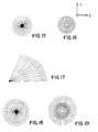
- FIGS. 15 thru 19show further xy plane surface patterns which, respectively, comprise radiating, concentric, circular, radiating fan, radiating with concentric, and radiating with intersecting polar, patterns.
- FIGS. 20 and 21are scanning electron micrographs at about 750 magnifications of a deproteinated bone specimens from a bone to metal implant showing the surface of the implant after bone removal (FIG. 20) and the surface of the bone after implant removal (FIG. 21) both show bone ingrowth into microgrooves within the bone implant surface, the width of such grooves being about 12 microns.
- FIGS. 22 and 23are higher magnification micrographs of deproteinated bone/implant specimen showing bone growth into the grooves of the inventive microgeometric surface patterns.
- FIG. 24is an elevational view of a cylindrical dental implant in which all implantable surfaces thereof are provided with the same linear longitudinal microgeometric pattern.
- FIG. 25is an enlarged upper site view of a buttress thread implant in which the anchor portion thereof has not been provided with a surface pattern while the proximal or collar portion thereof has been provided with a first pattern for purpose of bone interface and a second pattern above the first pattern for purposes of soft tissue attachment.
- FIG. 26is a tissue breakaway view showing implantation of a buttress thread implant into bone in which the implant anchor and the lower portion of the collar thereof has been provided with a bone adhesion surface while an upper part of the proximal collar has been provided with a soft tissue adhesion surface.
- FIG. 27is an enlarged view showing bone and tissue adhesion interfaces using the structure of FIG. 16 .
- FIG. 28is a tissue breakaway view showing implantation of an implant into bone including an abutment, in which all implant and abutment surface have been provided with bone or tissue adhesion interfaces respectively.
- FIG. 29is a schematic view showing the use of an elongated maxillofacial implant to support the maxilla bone relative to the sinus complex.
- FIG. 30is an enlarged view of a buttress thread dental implant, of the type of FIG. 26, which has been provided with the inventive ordered microgeometric surface on the collar.
- FIG. 31is an enlargement (at 170 magnifications) of the collar portion of FIG. 30, showing a pattern of continuous grooves and ridges, as depicted in FIG. 1 above.
- FIG. 32is an electron micrograph showing use of ax-axis discontinuous ridges and grooves, in both x and y axes, therein corresponding to the pattern of FIG. 3 above.
- FIG. 33is an electron micrograph, however, at 1,700 magnifications, of the views of FIGS. 32 or 34 below.
- FIG. 34is an electron micrograph of the surface pattern upon the collar of an implant similar to that shown in FIG. 30 in which the grooves thereof are continuous, as opposed to the x-axis discontinuous ridge and groove segments of FIG. 32, employed upon the collar of the implant of FIG. 35 below.
- FIG. 35is a 600-power electron micrograph enlargement of the collar of the implant shown in FIG. 32 . This was photographed on an angle to show ridge height and groove depth.
- FIG. 36is a micrograph of a prior art microgeometric surface pattern showing the randomness of such pattern.
- Bone tissueis the rigid supporting tissue constituting the principal component of almost all adult vertebrate skeletal structures. It exists in either dense or spongy form, known respectively as compact and cancellous bone.
- the typical bone cell sizeis of the order of about 10,000 nm, that is 10 microns.
- Bone tissueconsists of a chemical mixture of inorganic salts (65 to 70 percent) and various organic substances (30 to 35 percent) and is both hard and elastic. Its hardness is derived from inorganic constituents, principally calcium phosphate and calcium carbonate, with small amounts of fluorides, sulfates, and chlorides; its elasticity is derived from such organic substances as collagen, elastic cellular material, and fats.
- Internal tubular structures called Haversian canalscontain nerve tissues and blood vessels that provide bones with organic nourishment. Surrounding these canals is a somewhat porous tissue composed of thin plates, known as lamellae, and usually containing cavities filled with a network of connective tissue called marrow or myeloid tissue.
- Bone marrowaccounts for from 2 to 5 percent of the body weight of a person and consists of tissue of two types. Yellow bone marrow is made up principally of fat, and red bone marrow is tissue in which red and white blood cells and blood platelets originate.
- the external portions of bones, enclosing all the components mentioned above,include the compact and hardest of all bone tissue, which is in turn generally sheathed by a vascular, fibrous membrane known as the periosteum.
- implants of this inventioncomprise a plurality of separate zones of textured surface, each zone containing a different repetitive microgeometric design or pattern which is presented and exposed to the particular cell type for development of its unique colony growth.
- These different repetitive microgeometric textured design surfacesare intended to:
- (c)create a barrier that discourages the growth of soft tissue, particularly soft fibrous tissue, and thereby prevent the migration of soft tissue growth in bone tissue attachment surfaces of the implant.
- the implants of the inventioncan be provided from suitable and acceptable materials that are commercially available such as cast or wrought cobalt and chrome alloys, various grades of commercial titanium, titanium alloys, stainless steel alloys, thermoplastic resins such as polyethyletherketone, polyphenylene sulfide, ceramics, alumina, as well as combinations thereof.
- a surface consisting of 12- ⁇ m groove and ridgeshas been shown to increase the RBM (rat bone marrow) to RTF (rat tendon fibroblast) cell colony growth ratio to encourage bone cell growth over fibrous tissue growth.
- RBMrat bone marrow
- RTFrat tendon fibroblast
- the ratio of bone to soft tissue colony area increase, on a given surfaceis an important parameter in surface selection.
- the ratioindicates the relative stimulation or inhibition of cell growth on these surfaces (see FIG. 20 ). Theoretically, this ratio would be significant to provide advantage for growth of one or another cell type on a surface, with high ratios favoring bone cell growth and low ratios favoring fibrous tissue growth. Based on these ratios, a 2-micron indentation or groove provided a 32.8% decrease in bone/soft tissue growth, providing a significant advantage in soft cell tissue growth.
- the surfacecould be used to increase fibrous tissue cell growth; it can also be used to significantly orient growth of these cells.
- a 4-micron indentation or groove surfaceprovided a similar ratio, but it is based on lower overall growth rates. Therefore, if non-oriented fibrous cell growth is required, a flat control surface provides an inherent advantage to RTF tissue cells at a ratio of bone to soft tissue cell growth of approximately 0.6. This effect has been observed in vivo where smooth surfaces have been shown to favor formation of thick fibrous tissue capsule formation as compared to textured surfaces of the same composition, which show less fibrous capsule formation and more extensive osteointegration.
- the surface having the highest ratio of bone to soft tissue cell growthis the 12- ⁇ m/micron indentation or groove substrate.
- the basis of the ratiois the fact that this surface inhibits soft tissue colony growth by 53.1% relative to controls (FIG. 21 ). This is close to the maximal suppression of soft tissue cell growth seen on such microgeometrics. The same surface, however, does not maximally suppress bone cell growth (46.3% suppression relative to controls). See FIGS. 22 and 23.
- the differential suppressionresults in a 14.4% increase in bone/soft tissue growth relative to the control ratio. Where both cell types are present and compete for growth, this provides a significant advantage to bone colony growth. Bone cells grown on this surface also exhibits greatly enhanced directional growth in the x-axis. Such an in vivo surface favors bone over soft tissue growth and can be used to conduct directional bone growth.
- the textured substrateswere further studied to determine the preferable substrates and their structure for control of cell growth.
- the studywas conducted to determine the effect of a range of grooves on the control of cell growth.
- the experimental surfaceswere observed to cause oriented cell attachment and migration, resulting in elongated colony growth, which was accelerated in the x-direction (parallel to the axis of surface microgeometry) and inhibited in the y-direction (perpendicular to the axis of surface microgeometry) as shown in FIGS. 20-21.
- the cellsappeared to be “channelled” in the x-direction, as compared with control culture where outgrowing cells move randomly on flat surfaces.
- the most efficient “channelling”was observed on the 6- ⁇ m and 8 ⁇ m surfaces. On these surfaces, both hard and soft cell types were observed to attach and orient within the grooves. This resulted in enhanced x-axis growth and almost no y-axis growth by both cell types on these surfaces.
- a dental implant systemwhich includes at least an implant element and, in a given application, an abutment element, may be selectably surfaced in the fashion illustrated in FIGS. 1 thru 6 which show a variety of patterns which may comprise ordered microgeometric, repetitive surface patterns, and which may be applied to materials inclusive of titanium, stainless steel, plastics, ceramics, biocompatible glass and combinations thereof which materials may be coated with coatings inclusive hydroxyapatite, RBM roughening, titanium, plama sprayed, calcium sulfate, biocompatible glass, collagen, growth factor compounds, and combination thereof. More particularly, with reference to FIG.
- the subject ordered microgeometric repetitive patternsmay take the form of a multiplicity of alternating grooves 10 and ridges 12 in which each respective ridge and groove displays a width between about 6.0 to about 25 microns and a depth in a range between about 2 to about 25 microns.
- an infinite repeating pattern of co-parallel linear ridges and grooves having substantially equal widthdefines a micro textured surface of an implant or substrate as contemplated by the instant invention.
- FIG. 2In the embodiment of FIG. 2 is shown a surface in which alternating ridges 14 and grooves 16 increase y-axis in width with reference to a transverse axis relative to the axis of said ridges and grooves. Accordingly, with reference to types of tissues with which a transition of tissue type or gradient of tissue density exists, a textured surface of the type of FIG. 2 may be employed.
- FIG. 3is shown a surface pattern in which ridges 18 take the form of projections while grooves 20 take the form of recesses to thereby define a checkerboard configuration.
- ridges 18take the form of projections
- grooves 20take the form of recesses to thereby define a checkerboard configuration.
- ridges and groovesalternate with reference to both a x and y axes of a given surface.
- FIG. 4differs from that of FIG. 3 in that ridges 22 thereof form a bi-axial linear pattern. Similarly, grooves 24 of the embodiment of FIG. 4 define a x-y matrix formed of recesses that may assume a number of geometries.
- FIG. 5is shown embodiment of the invention in which circular depressions 26 define grooves or depressions while the areas therebetween, namely, spaces 28 define ridges or projections.
- alternating ridges and groovesencompasses a variety of microtexturized geometric patterns in which the ridges and grooves thereof while alternating relative to each other may themselves comprise any one of a variety of geometries inclusive of channels, rectangles, parallelograms, squares, circles and ovals.
- grooves 30define an xy matrix which is etched into a surface 32 such that surface 32 , when viewed relative to etched grooves 30 , comprises ridges.
- the width (or diameter) of a given grooveneed not correspond to that of its respective ridge, providing such widths fall within the above-referenced range of about 2 to 25 microns with a depth in a range of about 2 to about 25 microns. It has, thereby, through extensive experimentation as set forth above, been determined that a microgeometric repetitive pattern within the scope of the present invention may define a guide for preferential promotion of the rate, orientation and directionality of growth of colonies of cells of maxillofacial bone or tissue without requirement that the width of a ridge be equal to that of a groove in that it is, essentially, the groove of the microtexturized surface that defines the guide for preferential promotion of growth of colonies of cells. In most applications, it is desirable to maximize the density of grooves upon a given surface to thereby attain the desired cell growth effect; however, differing clinical environments will dictate use of different surface patterns and density if distribution of grooves.
- FIGS. 7 thru 14there is shown diagrammatic cross-sections which may be employed in association with the microgeometric textured configurations above described with reference to FIGS. 1 thru 6 .
- the views of FIGS. 7 thru 14illustrate the range of geometries which may be defined within the yz plane of the surface patterns.
- FIGS. 7 thru 9show variations in ridge width a, ridge and groove height b, and groove width c.
- ridge heightwill equal groove depth.
- Parameter dis the sum of ridge and groove width.
- FIG. 7The right side of FIG. 7 indicates that y-axis surfaces need not be linear.
- FIGS. 10 and 11show that the walls of the ridges and/or grooves may be yz sloped either inwardly or outwardly relative to the z-axis.
- FIGS. 12 and 13show that the transition from a y-axis ridge surface to a groove surface need not be a sharp one but, rather, may be curved.
- FIG. 14is shown a cross-sectional view of a pattern in which all yz surfaces are sinusoidal. In such embodiment, the potential for “bridging” between lines of cell colony growth is maximized since an abrupt delineation between ridges and grooves is not present.
- FIGS. 15 thru 19Shown in FIGS. 15 thru 19 are further xy surface patterns which are programmable through the use of processes selected from the process group consisting of laser etching, acid etching, mechanical etching and photolithography. More particularly, FIG. 15 comprises a radiating pattern. FIG. 16 a concentric circular pattern, FIG. 17 a radiating fan pattern, FIG. 18 a radiating/concentric pattern, and FIG. 19 a radiating pattern with an intersecting polar pattern. It is, therefrom, to be appreciated that an ordered microgeometric repetitive surface pattern may, within the scope of the invention, assume a wide variety of unidirectional linear, bi-axial linear, radial, radial and polar, non-linear, and differential linear or polar patterns.
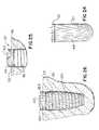
- FIG. 24there is shown a simple cylindrical implant element 40 of the present dental implant system in which both a platform section 42 and an anchor section 44 thereof are provided with a unidirectional linear repetitive surface pattern of the type of FIG. 1 above taken in combination with any of the cross sectional geometries of FIGS. 7 thru 14 above.
- a multiplicity of alternating ridges and groovesis applied to the entire lateral surface of implant 40 along an axis which is co-axial with the axis of surgical insertion of the implant into a maxo-facial bone or tissue.
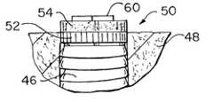
- FIG. 25is shown an upper portion of a buttress thread implant 46 which has been surgically inserted into bone 48 .
- the anchor sectionhas not been microtexturized while platform section 50 thereof has been provided with a first ordered microgeometric repetitive surface pattern as to a distal section 52 thereof while a proximal portion 54 has been provided with a second ordered geometric pattern more suitable for purpose of tissue (as opposed to bone) adhesion or interface.
- Such a second ordered patternexhibits a width of about 2 to about 25 microns and a depth in a range of about 2 to about 25 microns in that it has been determined that tissue, such as gum tissue, is more amenable to preferential promotion of rate, orientation and directionality of growth of colonies of cells if the width of grooves is somewhat smaller than that above discussed with reference to bone adhesion and interface.
- FIG. 26there is shown a further buttress thread implant 100 which has been surgically inserted within bone 48 .
- the entire lateral surface of the anchor of the buttress thread implanthas been furnished with the same first ordered repetitive surface 52 above described with reference to FIG. 25 .
- proximal region 154has been provided with a surface more suitable to tissue adhesion interface, namely, said second ordered pattern, while lower region 152 has been provided with the same pattern as anchor surface 53 .
- a gripping surface 60used for purposes of surgical insertion and for complemental receipt of an abutment element of a dental implant system.
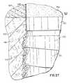
- FIG. 27comprises an enlarged view of a bone adhesion interface 162 which exists between bone 48 and the first ordered microgeometric repetitive of the anchor 53 of the implant of 100 . Also shown therein are lower and upper regions 152 and 154 of platform section 150 of the implant as well as an interface 165 of said upper region 154 with gum tissue 164 . Further shown is adhesion interfaces 163 between bone 48 and lower region 152 of platform 150 . Therefrom may be appreciated the effect of the inventive microgeometric repetitive surface patterns in the formation of bone and tissue adhesion interfaces, that is, the effect of which is to strengthen bone and tissue in the regions immediately surrounding a dental implant element.
- Micro-geometric patterns of this typemay be formed by various methods, including, without limitation, laser etching, acid etching, mechanical etching, and photo-lithography.
- FIG. 28is similar to the views of FIGS. 26 and 27, but for the use of a textured cylindrical anchor 244 , as opposed to a buttress thread anchor section, of a dental implant 200 .
- gingival epithelium 66 above gum tissue 164also referred to as the connective tissue, between the epithelium and the cortical bone 48 .
- an abutment 270secured upon implant projection 268 ) of a dental implant system, that has been provided with collars 254 having a microtexturized regions 266 to effect gum and epithelium tissue adhesion interfaces thereto.
- a collar 253 of implant 200has been provided with a microtexturized surface particularly adapted for bone adhesion interface 265 . It may, accordingly, from the view of FIG. 28, be appreciated that in a given application as many as five different microtexturized surfaces may be employed to maximize bone and tissue adhesion to one or another portion of an implant element and/or of an abutment element of a dental implant system. As such, different patterns of tissue or bone interface and adhesion, that is, differing forms of promotion of rate, orientation and directionality of growth of contacting colonies of cells will be achieved with reference to differing micro-textured surfaces of the implant material. Such interfaces are indicated by numerals 262 (implant anchor to bone interface), 265 (implant collar to bone interface), 266 (collar to gum) 272 .
- an implant 300may be used as a means of surgical support of a maxillofacial bone 302 by securement thereof to a bone 304 of the sinus complex.
- Such implantis of value in the area of reconstructive surgery and in dental procedures in which the cortical bone lacks sufficient strength or stability to otherwise receive and hold an implant element.
- the upper and lower ends of the implant 300will be provided with microtexturized surfaces as above described.
- FIGS. 30 thru 36are shown micrographs of the inventive microgeometric surfaces at magnifications ranging from 600 to 1700.
- FIG. 31is an enlarged view of a buttress thread dental implant, of the type of FIG. 26, which has been provided with the inventive ordered microgeometric surface.
- FIG. 35is an enlargement at 170 magnifications of the collar portion of FIG. 31, showing a pattern of discontinuous grooves and ridges, as depicted in FIG. 1 above
- FIG. 32is an electron micrograph comprising a further enlargement of the collar of FIG. 31, showing use of alternating ridges and grooves in both x and y axes, therein corresponding to the pattern of FIG. 3 above.
- FIG. 32is an electron micrograph, however, at 1,700 magnifications, of the view of FIG. 31 .
- FIG. 34is an electron micrograph of the surface pattern upon the thread structure of the implant of FIG.
- FIG. 35is a 600-power electron micrograph enlargement of the collar of the implant shown in FIG. 34 .
- the small longitudinal grooves thereinreflect laser-related melting, rather than a part of the microgeometric surface of the implant.
Landscapes
- Health & Medical Sciences (AREA)
- Oral & Maxillofacial Surgery (AREA)
- Life Sciences & Earth Sciences (AREA)
- Animal Behavior & Ethology (AREA)
- General Health & Medical Sciences (AREA)
- Public Health (AREA)
- Veterinary Medicine (AREA)
- Orthopedic Medicine & Surgery (AREA)
- Epidemiology (AREA)
- Dentistry (AREA)
- Engineering & Computer Science (AREA)
- Transplantation (AREA)
- Chemical & Material Sciences (AREA)
- Dermatology (AREA)
- Medicinal Chemistry (AREA)
- Ceramic Engineering (AREA)
- Cardiology (AREA)
- Biomedical Technology (AREA)
- Heart & Thoracic Surgery (AREA)
- Vascular Medicine (AREA)
- Dental Prosthetics (AREA)
- Materials For Medical Uses (AREA)
- Dental Tools And Instruments Or Auxiliary Dental Instruments (AREA)
- Prostheses (AREA)
Abstract
Description
Claims (23)
Priority Applications (14)
| Application Number | Priority Date | Filing Date | Title |
|---|---|---|---|
| US09/500,038US6419491B1 (en) | 1993-11-02 | 2000-02-08 | Dental implant system with repeating microgeometric surface patterns |
| US09/605,142US6454569B1 (en) | 1993-11-02 | 2000-06-26 | Dental implant having a dual bio-affinity collar |
| TR2018/10436TTR201810436T4 (en) | 2000-02-08 | 2001-02-01 | Maxillofacial surgical elements with sequential microgeometric surface models. |
| PCT/US2001/003313WO2001058374A2 (en) | 2000-02-08 | 2001-02-01 | Maxillofacial surgical elements having ordered microgeometric surface patterns |
| ES01908781.6TES2564458T3 (en) | 2000-02-08 | 2001-02-01 | Maxillofacial surgical elements that have ordered microgeometric surface patterns |
| EP01908781.6AEP1255502B1 (en) | 2000-02-08 | 2001-02-01 | Maxillofacial surgical elements having ordered microgeometric surface patterns |
| ES12157708.4TES2682306T3 (en) | 2000-02-08 | 2001-02-01 | Maxillofacial surgical elements that have ordered microgeometric surface patterns |
| EP12157708.4AEP2921129B1 (en) | 2000-02-08 | 2001-02-01 | Maxillofacial surgical elements having ordered microgeometric surface patterns |
| AU2001236614AAU2001236614A1 (en) | 2000-02-08 | 2001-02-01 | Maxillofacial surgical elements having ordered microgeometric surface patterns |
| US09/784,284US20010039454A1 (en) | 1993-11-02 | 2001-02-16 | Orthopedic implants having ordered microgeometric surface patterns |
| US10/081,478US20020133232A1 (en) | 1993-11-02 | 2002-02-25 | Microstructured dual sided membrane for tissue growth and regeneration |
| US10/237,355US20040006396A1 (en) | 1993-11-02 | 2002-09-06 | Transcutaneous devices having nueral interface |
| US11/799,262US20080015616A1 (en) | 1993-11-02 | 2007-05-01 | Orthopedic implants having ordered microgeometric surface patterns |
| HK16103332.3AHK1215368B (en) | 2000-02-08 | 2016-03-22 | Maxillofacial surgical elements having ordered microgeometric surface patterns |
Applications Claiming Priority (5)
| Application Number | Priority Date | Filing Date | Title |
|---|---|---|---|
| US14679093A | 1993-11-02 | 1993-11-02 | |
| US39080595A | 1995-02-15 | 1995-02-15 | |
| US63971296A | 1996-04-29 | 1996-04-29 | |
| US99624497A | 1997-12-22 | 1997-12-22 | |
| US09/500,038US6419491B1 (en) | 1993-11-02 | 2000-02-08 | Dental implant system with repeating microgeometric surface patterns |
Related Parent Applications (2)
| Application Number | Title | Priority Date | Filing Date |
|---|---|---|---|
| US08/996,224Continuation-In-PartUS6147666A (en) | 1997-12-22 | 1997-12-22 | Multipole liquid crystal display |
| US99624497AContinuation-In-Part | 1993-11-02 | 1997-12-22 |
Related Child Applications (4)
| Application Number | Title | Priority Date | Filing Date |
|---|---|---|---|
| US09/605,142Continuation-In-PartUS6454569B1 (en) | 1993-11-02 | 2000-06-26 | Dental implant having a dual bio-affinity collar |
| US09/784,284Continuation-In-PartUS20010039454A1 (en) | 1993-11-02 | 2001-02-16 | Orthopedic implants having ordered microgeometric surface patterns |
| US10/081,478Continuation-In-PartUS20020133232A1 (en) | 1993-11-02 | 2002-02-25 | Microstructured dual sided membrane for tissue growth and regeneration |
| US10/237,355Continuation-In-PartUS20040006396A1 (en) | 1993-11-02 | 2002-09-06 | Transcutaneous devices having nueral interface |
Publications (1)
| Publication Number | Publication Date |
|---|---|
| US6419491B1true US6419491B1 (en) | 2002-07-16 |
Family
ID=23987779
Family Applications (1)
| Application Number | Title | Priority Date | Filing Date |
|---|---|---|---|
| US09/500,038Expired - LifetimeUS6419491B1 (en) | 1993-11-02 | 2000-02-08 | Dental implant system with repeating microgeometric surface patterns |
Country Status (6)
| Country | Link |
|---|---|
| US (1) | US6419491B1 (en) |
| EP (2) | EP2921129B1 (en) |
| AU (1) | AU2001236614A1 (en) |
| ES (2) | ES2564458T3 (en) |
| TR (1) | TR201810436T4 (en) |
| WO (1) | WO2001058374A2 (en) |
Cited By (123)
| Publication number | Priority date | Publication date | Assignee | Title |
|---|---|---|---|---|
| US20030054319A1 (en)* | 2001-09-17 | 2003-03-20 | Christopher Gervais | Impression post and temporary abutment and method of making dental restoration |
| US20030059933A1 (en)* | 1999-08-10 | 2003-03-27 | Tresco Patrick A. | Bioartificial device for propagation of tissue, preparation and uses thereof |
| US20030065401A1 (en)* | 2001-01-25 | 2003-04-03 | Mark Amrich | Textured surface having undercut micro recesses in a surface |
| US20040049201A1 (en)* | 2001-08-08 | 2004-03-11 | Wolfgang Dinkelacker | Implant comprising a grooved structure |
| US6716250B2 (en)* | 2001-11-05 | 2004-04-06 | Ramin Ganjianpour | Modular femoral prosthesis |
| US20040121286A1 (en)* | 2002-06-28 | 2004-06-24 | Zimmer Dental Inc. | Organic shaped interface for dental implant devices |
| WO2004058091A1 (en)* | 2002-12-30 | 2004-07-15 | Nobel Biocare Ab (Publ) | Implant arrangement |
| WO2004084755A1 (en) | 2003-03-26 | 2004-10-07 | Young-Taek Sul | Helical implant |
| US20050119758A1 (en)* | 2003-07-30 | 2005-06-02 | Bio-Lok International Inc. | Surgical implant for promotion of osseo-integration |
| US20050147942A1 (en)* | 2001-12-21 | 2005-07-07 | Jan Hall | Method for producing a surface structure on an implant, and such an implant |
| US20050191248A1 (en)* | 2003-11-10 | 2005-09-01 | Angiotech International Ag | Medical implants and fibrosis-inducing agents |
| EP1570804A1 (en)* | 2004-03-05 | 2005-09-07 | Straumann Holding AG | Dental device and method to manufacture the same using injection molding |
| US20050209684A1 (en)* | 2004-03-04 | 2005-09-22 | Harold Alexander | Surgical stent having micro-geometric patterned surface |
| US20050211680A1 (en)* | 2003-05-23 | 2005-09-29 | Mingwei Li | Systems and methods for laser texturing of surfaces of a substrate |
| US20050260540A1 (en)* | 2001-12-21 | 2005-11-24 | Jan Hall | Implant, and method and system for producing such an implant |
| US20060040236A1 (en)* | 2004-08-17 | 2006-02-23 | Schmitt Stephen M | Design and manufacture of dental implant restorations |
| US20060063133A1 (en)* | 2002-09-30 | 2006-03-23 | Robert Schroering | Dental implant |
| WO2006070957A1 (en)* | 2004-12-31 | 2006-07-06 | Jeil Medical Corporation | Orthodontic anchoring device and method for using the anchoring device |
| US7097453B1 (en)* | 2003-04-01 | 2006-08-29 | Schroering Jr Robert Lewis | Dental implant |
| US20060246398A1 (en)* | 2003-11-04 | 2006-11-02 | Friadent Gmbh | Dental implant component |
| US20060246397A1 (en)* | 2003-11-05 | 2006-11-02 | Friadent Gmbh | Multi part non metal implant |
| US20060286509A1 (en)* | 2005-06-17 | 2006-12-21 | Zimmer Dental, Inc. | Dental restorative system and components |
| US20060286508A1 (en)* | 2005-06-17 | 2006-12-21 | Zimmer Dental, Inc. | Dental restorative system and components |
| WO2006114098A3 (en)* | 2005-04-26 | 2007-02-15 | Univ Aarhus | Biocompatible material for surgical implants and cell guiding tissue culture surfaces |
| US20070037122A1 (en)* | 2005-06-17 | 2007-02-15 | Zimmer Dental, Inc. | Dental restorative system and components |
| WO2007051221A1 (en)* | 2005-11-04 | 2007-05-10 | Craig Mclachlan | Substrate for tissue growth |
| JP2007515246A (en)* | 2003-12-22 | 2007-06-14 | ノベル バイオケアー アーベー (パブル) | Implant |
| US20070190492A1 (en)* | 2006-02-15 | 2007-08-16 | Dental Implant Technologies, Inc. | Computer machined dental tooth system and method |
| US20070225785A1 (en)* | 2006-02-13 | 2007-09-27 | Medtronic, Inc. | Medical devices having textured surfaces |
| US20070269766A1 (en)* | 2003-12-11 | 2007-11-22 | Jan Hall | Implant |
| US20080064008A1 (en)* | 2006-09-06 | 2008-03-13 | Dental Implant Technologies, Inc. | Methods for the virtual design and computer manufacture of intra oral devices |
| US20080085489A1 (en)* | 2006-10-07 | 2008-04-10 | Dental Implant Technologies, Inc. | Surgical guides and methods for positioning artificial teeth and dental implants |
| US20080091208A1 (en)* | 2006-10-11 | 2008-04-17 | Astra Tech Ab | Implant |
| WO2008079700A3 (en)* | 2006-12-19 | 2008-08-28 | Pavad Medical Inc | Implant for treatment of sleep disorders |
| US20080228303A1 (en)* | 2007-03-13 | 2008-09-18 | Schmitt Stephen M | Direct manufacture of dental and medical devices |
| US20080261176A1 (en)* | 2007-04-23 | 2008-10-23 | Nobel Biocare Services Ag | Dental implant and dental component connection |
| EP1991169A1 (en)* | 2006-02-08 | 2008-11-19 | R.T.M. S.p.A. | A method for laser treatment of implantable devices, implantable devices obtained using said method, and a laser system for treatment of implantable devices |
| US20090155742A1 (en)* | 2007-12-14 | 2009-06-18 | Inha-Industry Partnership Institute | Implant having microgrooves and a method for preparing the same |
| US20090269719A1 (en)* | 2008-04-16 | 2009-10-29 | Pierre Malek | Radicular pivot with a variable depth progressive thread allowing the removal thereof |
| EP2114482A2 (en)* | 2007-01-30 | 2009-11-11 | Medtronic Vascular Inc. | Textured medical devices |
| US20090325126A1 (en)* | 2003-05-21 | 2009-12-31 | Ophir Fromovich | Condensing skeletal implant that facilitate insertions |
| US20100003638A1 (en)* | 2008-07-02 | 2010-01-07 | Michael Collins | Modular implant with secured porous portion |
| DE102008060991A1 (en)* | 2008-12-08 | 2010-06-10 | MAX-PLANCK-Gesellschaft zur Förderung der Wissenschaften e.V. | Subtrate for selection and specific influence on the function of cells |
| US20100240010A1 (en)* | 2009-03-23 | 2010-09-23 | Holmstroem Johan | Fixture |
| WO2010089698A3 (en)* | 2009-02-04 | 2010-09-30 | Mid Corp. | A system, method and apparatus for implementing dental implants |
| US7806693B2 (en) | 2007-04-23 | 2010-10-05 | Nobel Biocare Services Ag | Dental implant |
| US20100256773A1 (en)* | 2007-07-03 | 2010-10-07 | Vlaamse Instelling Voor Technologisch Onderzoek N.V. (Vito) | Surgical implant composed of a porous core and a dense surface layer |
| US20100316971A1 (en)* | 2002-06-10 | 2010-12-16 | Biomed Est. | Bone-adaptive surface structure |
| US20110183292A1 (en)* | 2007-08-03 | 2011-07-28 | Claus Daniel | Material with a repetitive pattern of micro-features for application in a living organism and method of fabrication |
| US20110200969A1 (en)* | 2003-04-01 | 2011-08-18 | Robert Schroering | Band of Connective Tissue Grooves for Use with a Dental Implant or a Separate Abutment for a Dental Implant |
| GB2479274A (en)* | 2009-02-04 | 2011-10-05 | Mid Corp | A system, method and apparatus for implementing dental implants |
| US8057230B1 (en) | 2008-02-20 | 2011-11-15 | Folsom Jr Aubrey C | Ceramic and metal composite dental implant |
| US8075312B2 (en) | 2005-08-30 | 2011-12-13 | Zimmer Dental, Inc. | Dental implant with improved osseointegration features |
| EP2394602A1 (en)* | 2010-06-10 | 2011-12-14 | Astra Tech AB | A dental fixture |
| US20110313513A1 (en)* | 2007-07-30 | 2011-12-22 | Alfred David Johnson | Method and devices for preventing restenosis in cardiovascular stents |
| US8231387B2 (en) | 2008-07-02 | 2012-07-31 | Zimmer, Inc. | Porous implant with non-porous threads |
| US8348669B1 (en) | 2009-11-04 | 2013-01-08 | Bankruptcy Estate Of Voxelogix Corporation | Surgical template and method for positioning dental casts and dental implants |
| US20130011811A1 (en)* | 2009-11-27 | 2013-01-10 | Zda-Zirconia Developpement & Applications | Implant endo-osseux et procede de sa fabrication |
| US20130017512A1 (en)* | 2011-07-11 | 2013-01-17 | Yu-Hong Tzeng | Dental implant system for promoting osseointegration |
| US8366442B2 (en) | 2006-02-15 | 2013-02-05 | Bankruptcy Estate Of Voxelogix Corporation | Dental apparatus for radiographic and non-radiographic imaging |
| US8414654B1 (en) | 2011-11-23 | 2013-04-09 | Amendia, Inc. | Bone implants and method of manufacture |
| US8425231B1 (en) | 2012-01-23 | 2013-04-23 | Mark N. Hochman | Soft-tissue preservation temporary (shell) immediate-implant abutment method and device |
| WO2013077897A1 (en)* | 2011-11-23 | 2013-05-30 | Amendia, Inc. | Bone implants and method of manufacture |
| US8535388B2 (en) | 2011-11-23 | 2013-09-17 | Timothy Ganey | Bone graft |
| US8562346B2 (en) | 2005-08-30 | 2013-10-22 | Zimmer Dental, Inc. | Dental implant for a jaw with reduced bone volume and improved osseointegration features |
| US8602782B2 (en) | 2009-11-24 | 2013-12-10 | Zimmer Dental, Inc. | Porous implant device with improved core |
| US20140080093A1 (en)* | 2006-10-16 | 2014-03-20 | Natural Dental Implants Ag | Customized Dental Prosthesis For Periodontal or Osseointegration, and Related System and Methods |
| WO2014052488A1 (en) | 2012-09-28 | 2014-04-03 | Evollution Ip Holdings, Inc. | Dental implant with laser-etched platform switching beveled collar surface |
| US20140205971A1 (en)* | 2013-01-18 | 2014-07-24 | The Trustees Of The Stevens Institute Of Technology | Modification of root form dental implants for accelerated tissue regeneration |
| US8814567B2 (en) | 2005-05-26 | 2014-08-26 | Zimmer Dental, Inc. | Dental implant prosthetic device with improved osseointegration and esthetic features |
| US8851891B2 (en) | 2008-11-06 | 2014-10-07 | Zimmer Dental, Inc. | Expandable bone implant |
| US20140324186A1 (en)* | 2011-11-15 | 2014-10-30 | B6 Sigma, Inc. | Medical Implants with Enhanced Osseointegration |
| US8899982B2 (en) | 2008-07-02 | 2014-12-02 | Zimmer Dental, Inc. | Implant with structure for securing a porous portion |
| US9095396B2 (en) | 2008-07-02 | 2015-08-04 | Zimmer Dental, Inc. | Porous implant with non-porous threads |
| US9149345B2 (en) | 2007-08-30 | 2015-10-06 | Zimmer Dental, Inc. | Multiple root implant |
| EP2811926A4 (en)* | 2012-02-09 | 2015-10-14 | Orthopedic Medical Channels Llc | BONE SCREW AND METHOD FOR THE PRODUCTION THEREOF |
| US9168110B2 (en) | 2012-05-29 | 2015-10-27 | Biomet 3I, Llc | Dental implant system having enhanced soft-tissue growth features |
| US9179954B2 (en) | 2011-11-23 | 2015-11-10 | Vivex Biomedical, Inc. | Bone screw fastener |
| EP1255502B1 (en)* | 2000-02-08 | 2015-12-09 | Evollution IP Holdings, Inc. | Maxillofacial surgical elements having ordered microgeometric surface patterns |
| US9220581B2 (en) | 2011-02-18 | 2015-12-29 | Zimmer Dental, Inc. | Porous implant device for supporting a denture |
| US9283057B2 (en) | 2011-02-02 | 2016-03-15 | Mid Corp. | System, apparatus and method for implementing implants |
| US20160172223A1 (en)* | 2013-08-20 | 2016-06-16 | Murata Machinery, Ltd. | Gas purge device and gas purge method |
| US9452032B2 (en) | 2012-01-23 | 2016-09-27 | Biomet 3I, Llc | Soft tissue preservation temporary (shell) immediate-implant abutment with biological active surface |
| US9474588B2 (en) | 2012-01-23 | 2016-10-25 | Biomet 3I, Llc | Method and apparatus for recording spatial gingival soft tissue relationship to implant placement within alveolar bone for immediate-implant placement |
| US9681930B2 (en) | 2014-12-15 | 2017-06-20 | Jjgc Industria E Comercio De Materiais Dentarious S/A | Implants for enhanced anchoring within bone |
| US9700390B2 (en) | 2014-08-22 | 2017-07-11 | Biomet 3I, Llc | Soft-tissue preservation arrangement and method |
| US9707058B2 (en) | 2009-07-10 | 2017-07-18 | Zimmer Dental, Inc. | Patient-specific implants with improved osseointegration |
| WO2017142405A1 (en)* | 2016-02-16 | 2017-08-24 | Materiomics B.V. | Surface topographies for altering the physiology of living cells |
| US9861455B2 (en) | 2013-07-30 | 2018-01-09 | TI Intellectual Property Inc. | Dental implant system |
| USD816841S1 (en) | 2014-12-15 | 2018-05-01 | Jjgc Industria E Comercio De Materiais Dentarios S/A | Bone implant |
| JP2018079067A (en)* | 2016-11-16 | 2018-05-24 | 慶達科技股▲ふん▼有限公司 | Root implant |
| WO2018080308A3 (en)* | 2016-10-28 | 2018-07-05 | Materiomics B.V. | Surface topographies for stimulating endothelialization |
| US10052144B2 (en) | 2007-11-19 | 2018-08-21 | Orthopedic Medical Channels, Llc | Bone screw and method for manufacturing the same |
| US20190063478A1 (en)* | 2015-10-09 | 2019-02-28 | Dublin City University | Interference fit fastener and method of fabricating same |
| US10449018B2 (en) | 2015-03-09 | 2019-10-22 | Stephen J. Chu | Gingival ovate pontic and methods of using the same |
| US10478311B2 (en) | 2017-08-14 | 2019-11-19 | Globus Medical, Inc. | Medical devices including titanium surface treatment |
| US10543061B2 (en)* | 2014-10-03 | 2020-01-28 | 3M Innovative Properties Company | Methods for managing the scattering of incident light and articles created therefrom |
| US10603093B2 (en) | 2015-12-01 | 2020-03-31 | Industrial Technology Research Institute | Bone implant and manufacturing method thereof |
| WO2020222035A1 (en) | 2019-04-30 | 2020-11-05 | Universidade Do Minho | Dental implant, process of obtention and uses thereof |
| US10898301B2 (en) | 2016-05-05 | 2021-01-26 | Jjgc Industria E Comercio De Materiais Dentarios S.A. | Prosthetic assembly and method for producing the same |
| US10945845B2 (en) | 2012-05-30 | 2021-03-16 | New York University | Tissue repair devices and scaffolds |
| US11058521B2 (en)* | 2014-08-18 | 2021-07-13 | University of Central Oklahoma | Method and apparatus for improving osseointegration, functional load, and overall strength of intraosseous implants |
| WO2021174325A1 (en)* | 2020-03-05 | 2021-09-10 | Implacil De Bortoli Material Odontológico | Dental implant |
| US20220031429A1 (en)* | 2014-04-30 | 2022-02-03 | Ceramedica, Inc. | Osseointegrative surgical implant and implant surgical kit |
| CN114081605A (en)* | 2021-12-24 | 2022-02-25 | 北京理贝尔生物工程研究所有限公司 | Intramedullary nail assembly |
| CN114306733A (en)* | 2022-03-02 | 2022-04-12 | 北京大学口腔医学院 | Degradable composite guided bone regeneration membrane with shaping support performance |
| US11419735B2 (en) | 2020-12-18 | 2022-08-23 | Spine Wave, Inc. | Expandable TLIF device and related insertion and grafting instrumentation |
| US11439726B2 (en) | 2018-12-03 | 2022-09-13 | Osseomimetic, LLC | Surgical implants |
| CN116616848A (en)* | 2023-05-26 | 2023-08-22 | 浙江大学 | A kind of occluder with topological microstructure on the surface and its preparation method |
| US20230293269A1 (en)* | 2021-06-17 | 2023-09-21 | Beijing Vanjewel Medical Tech Co., Ltd | Dental implant with nano bacteriostatic structure ring at transgingival part and machining method thereof |
| US11806028B1 (en) | 2022-10-04 | 2023-11-07 | Restor3D, Inc. | Surgical guides and processes for producing and using the same |
| US20230390089A1 (en)* | 2022-06-06 | 2023-12-07 | Sentronic International Corp. | Implant |
| US11850144B1 (en) | 2022-09-28 | 2023-12-26 | Restor3D, Inc. | Ligament docking implants and processes for making and using same |
| US20240024080A1 (en)* | 2022-07-21 | 2024-01-25 | Anthogyr | Method for manufacturing an abutment for receiving a dental prosthesis |
| USD1013876S1 (en) | 2020-01-08 | 2024-02-06 | Restor3D, Inc. | Osteotomy wedge |
| USD1013875S1 (en) | 2020-01-08 | 2024-02-06 | Restor3D, Inc. | Spinal implant |
| US11960266B1 (en) | 2023-08-23 | 2024-04-16 | Restor3D, Inc. | Patient-specific medical devices and additive manufacturing processes for producing the same |
| US12029653B1 (en) | 2023-06-14 | 2024-07-09 | Spine Wave, Inc. | Medical implant having a textured tissue contact surface |
| USD1051384S1 (en) | 2023-03-24 | 2024-11-12 | Restor3D, Inc. | Bone fixation pin |
| USD1052732S1 (en) | 2023-05-25 | 2024-11-26 | Restor3D, Inc. | Subtalar wedge |
| USD1053353S1 (en) | 2023-03-24 | 2024-12-03 | Restor3D, Inc. | Orthopedic screw |
| USD1071220S1 (en) | 2020-01-08 | 2025-04-15 | Restor3D, Inc. | Osteotomy wedge |
| USD1084338S1 (en)* | 2021-02-25 | 2025-07-15 | Meticuly Company Limited | Medical implant |
Families Citing this family (9)
| Publication number | Priority date | Publication date | Assignee | Title |
|---|---|---|---|---|
| US20040006396A1 (en)* | 1993-11-02 | 2004-01-08 | Ricci John L. | Transcutaneous devices having nueral interface |
| US20010039454A1 (en)* | 1993-11-02 | 2001-11-08 | John Ricci | Orthopedic implants having ordered microgeometric surface patterns |
| US20050043820A1 (en)* | 2001-10-12 | 2005-02-24 | James Browning | Biomaterial comprising microfeatures |
| DE102006011629A1 (en)* | 2006-03-08 | 2007-09-13 | Mircoceram Gmbh | Implants e.g. dental implant, making method, involves providing surface structuring in base body using laser, where base body is made of zirconium dioxide and high-stable mixing ceramics |
| DE102007046879B4 (en) | 2007-09-28 | 2012-07-05 | Microceram Gmbh | Dental implant |
| ITUB20155412A1 (en)* | 2015-11-10 | 2017-05-10 | Torino Politecnico | SURFACE OF MODIFIED TITANIUM, MEDICAL PLANT EQUIPPED WITH ONE OR MORE OF THESE SURFACES AND PROCEDURE FOR REALIZING SUCH A SURFACE. |
| AU2017356025B2 (en)* | 2016-11-10 | 2020-05-14 | Nantoh. Co., Ltd | Biological tissue rootage face, implant, method for forming biological tissue rootage face, and method for producing implant |
| FR3097117B1 (en) | 2019-06-13 | 2025-08-22 | Global D | BIO-FUNCTIONALIZED IMPLANT PART |
| IT202300009309A1 (en)* | 2023-05-10 | 2024-11-10 | Kalodon S R L | ZYGOMATIC IMPLANT |
Citations (11)
| Publication number | Priority date | Publication date | Assignee | Title |
|---|---|---|---|---|
| US4553272A (en) | 1981-02-26 | 1985-11-19 | University Of Pittsburgh | Regeneration of living tissues by growth of isolated cells in porous implant and product thereof |
| US4826434A (en)* | 1986-10-20 | 1989-05-02 | Steri-Oss, Inc. | Dental implant |
| US5202227A (en) | 1989-06-03 | 1993-04-13 | Kanegafuchi Kagaku Kogyo Kabushiki Kaisha | Control of cell arrangement |
| WO1995012369A1 (en) | 1993-11-02 | 1995-05-11 | Hospital For Joint Diseases | Control of cell growth |
| US5588838A (en)* | 1992-10-28 | 1996-12-31 | Astra Aktiebolag | Fixture for use in a dental implant system |
| US5607607A (en) | 1993-11-01 | 1997-03-04 | Naiman; Charles S. | System and assemblage for producing microtexturized substratesand implants |
| US5716412A (en)* | 1996-09-30 | 1998-02-10 | Johnson & Johnson Professional, Inc. | Implantable article with ablated surface |
| US5833641A (en) | 1994-02-18 | 1998-11-10 | The University Court Of The University Of Glasgow | Wound healing material |
| US5976826A (en) | 1993-10-04 | 1999-11-02 | President And Fellows Of Harvard College | Device containing cytophilic islands that adhere cells separated by cytophobic regions |
| US5989027A (en)* | 1995-12-08 | 1999-11-23 | Sulzer Calcitek Inc. | Dental implant having multiple textured surfaces |
| US6174167B1 (en)* | 1998-12-01 | 2001-01-16 | Woehrle Peter S. | Bioroot endosseous implant |
Family Cites Families (11)
| Publication number | Priority date | Publication date | Assignee | Title |
|---|---|---|---|---|
| US4320891A (en) | 1980-04-21 | 1982-03-23 | Howard Ingram Cairns | Nipple operated animal watering valve |
| DE3435124C2 (en) | 1984-09-25 | 1987-03-05 | Kali Und Salz Ag, 3500 Kassel | Process for the production of potassium chloride with more than 55 wt.% K↓2↓O from the fine decomposition salt of carnallite decomposition |
| SE450623B (en) | 1984-11-07 | 1987-07-13 | Dan Lundgren | ELEMENTS OF CONTROLLED TISSUE INVESTMENT IN SURGICAL INTERVENTIONED AREAS |
| US4778469A (en) | 1986-11-04 | 1988-10-18 | Pfizer Hospital Products Group Inc. | Method of forming tissue ingrowth surface on surgical implants |
| BE1001511A4 (en) | 1988-03-15 | 1989-11-14 | Vermeire Dirk Victor | HIP prosthesis. |
| US5011494A (en) | 1988-09-16 | 1991-04-30 | Clemson University | Soft tissue implant with micron-scale surface texture to optimize anchorage |
| US5094618A (en) | 1991-04-26 | 1992-03-10 | Coltene/Whaledent, Inc. | Intermittent threaded dental posts |
| US5316478A (en) | 1991-08-02 | 1994-05-31 | Wellesley Research Associates, Inc. | Dental post with cutting surfaces |
| US6419491B1 (en)* | 1993-11-02 | 2002-07-16 | Bio-Lok International, Inc. | Dental implant system with repeating microgeometric surface patterns |
| US20010039454A1 (en)* | 1993-11-02 | 2001-11-08 | John Ricci | Orthopedic implants having ordered microgeometric surface patterns |
| US5571017A (en) | 1994-10-05 | 1996-11-05 | Core-Vent Corporation | Selective surface, externally-threaded endosseous dental implant |
- 2000
- 2000-02-08USUS09/500,038patent/US6419491B1/ennot_activeExpired - Lifetime
- 2001
- 2001-02-01ESES01908781.6Tpatent/ES2564458T3/ennot_activeExpired - Lifetime
- 2001-02-01ESES12157708.4Tpatent/ES2682306T3/ennot_activeExpired - Lifetime
- 2001-02-01EPEP12157708.4Apatent/EP2921129B1/ennot_activeExpired - Lifetime
- 2001-02-01EPEP01908781.6Apatent/EP1255502B1/ennot_activeExpired - Lifetime
- 2001-02-01WOPCT/US2001/003313patent/WO2001058374A2/enactiveApplication Filing
- 2001-02-01AUAU2001236614Apatent/AU2001236614A1/ennot_activeAbandoned
- 2001-02-01TRTR2018/10436Tpatent/TR201810436T4/enunknown
Patent Citations (11)
| Publication number | Priority date | Publication date | Assignee | Title |
|---|---|---|---|---|
| US4553272A (en) | 1981-02-26 | 1985-11-19 | University Of Pittsburgh | Regeneration of living tissues by growth of isolated cells in porous implant and product thereof |
| US4826434A (en)* | 1986-10-20 | 1989-05-02 | Steri-Oss, Inc. | Dental implant |
| US5202227A (en) | 1989-06-03 | 1993-04-13 | Kanegafuchi Kagaku Kogyo Kabushiki Kaisha | Control of cell arrangement |
| US5588838A (en)* | 1992-10-28 | 1996-12-31 | Astra Aktiebolag | Fixture for use in a dental implant system |
| US5976826A (en) | 1993-10-04 | 1999-11-02 | President And Fellows Of Harvard College | Device containing cytophilic islands that adhere cells separated by cytophobic regions |
| US5607607A (en) | 1993-11-01 | 1997-03-04 | Naiman; Charles S. | System and assemblage for producing microtexturized substratesand implants |
| WO1995012369A1 (en) | 1993-11-02 | 1995-05-11 | Hospital For Joint Diseases | Control of cell growth |
| US5833641A (en) | 1994-02-18 | 1998-11-10 | The University Court Of The University Of Glasgow | Wound healing material |
| US5989027A (en)* | 1995-12-08 | 1999-11-23 | Sulzer Calcitek Inc. | Dental implant having multiple textured surfaces |
| US5716412A (en)* | 1996-09-30 | 1998-02-10 | Johnson & Johnson Professional, Inc. | Implantable article with ablated surface |
| US6174167B1 (en)* | 1998-12-01 | 2001-01-16 | Woehrle Peter S. | Bioroot endosseous implant |
Non-Patent Citations (4)
| Title |
|---|
| Chehroudi et al, J. Biomedical Materials Research, vol. 24, 1203-1219 (1990). Titanium-coated micromachined grooves of different dimensions affect epithelial cells differently in vivo. |
| Clark et al Development 108, 635-644 1990. Topographical Control of Cell Behavior: II multiple grooved substrate. |
| Ricci et al, Mat. Res. Soc. Symp. Proc., vol. 252 (1992) The Influence of Surface Microgeometry on Fibroblast Colonization of Synthetic Surfaces. |
| Ricci et al, Meeting of Society of Biomaterials 1991, Tendon and Bone Cell Colony Formation on striated Surfaces. |
Cited By (221)
| Publication number | Priority date | Publication date | Assignee | Title |
|---|---|---|---|---|
| US20060140918A1 (en)* | 1999-08-10 | 2006-06-29 | Tresco Patrick A | Bioartificial device for propagation of tissue, preparation and uses thereof |
| US20030059933A1 (en)* | 1999-08-10 | 2003-03-27 | Tresco Patrick A. | Bioartificial device for propagation of tissue, preparation and uses thereof |
| EP1255502B1 (en)* | 2000-02-08 | 2015-12-09 | Evollution IP Holdings, Inc. | Maxillofacial surgical elements having ordered microgeometric surface patterns |
| US20030065401A1 (en)* | 2001-01-25 | 2003-04-03 | Mark Amrich | Textured surface having undercut micro recesses in a surface |
| US7850862B2 (en) | 2001-01-25 | 2010-12-14 | Tecomet Inc. | Textured surface having undercut micro recesses in a surface |
| US7018418B2 (en)* | 2001-01-25 | 2006-03-28 | Tecomet, Inc. | Textured surface having undercut micro recesses in a surface |
| US20060129161A1 (en)* | 2001-01-25 | 2006-06-15 | Tecomet, Inc. | Textured surface having undercut micro recesses in a surface |
| US20040049201A1 (en)* | 2001-08-08 | 2004-03-11 | Wolfgang Dinkelacker | Implant comprising a grooved structure |
| US7137816B2 (en)* | 2001-09-17 | 2006-11-21 | Zimmer Dental Inc. | Impression post and temporary abutment and method of making dental restoration |
| US20030054319A1 (en)* | 2001-09-17 | 2003-03-20 | Christopher Gervais | Impression post and temporary abutment and method of making dental restoration |
| US6716250B2 (en)* | 2001-11-05 | 2004-04-06 | Ramin Ganjianpour | Modular femoral prosthesis |
| US9737392B2 (en) | 2001-12-21 | 2017-08-22 | Nobel Biocare Services Ag | Implant, and method and system for producing such an implant |
| US8764443B2 (en) | 2001-12-21 | 2014-07-01 | Nobel Biocare Services Ag | Method for producing a surface structure on an implant, and such an implant |
| US8827703B2 (en) | 2001-12-21 | 2014-09-09 | Nobel Biocare Services Ag | Implant, and method and system for producing such an implant |
| US20050260540A1 (en)* | 2001-12-21 | 2005-11-24 | Jan Hall | Implant, and method and system for producing such an implant |
| US20050147942A1 (en)* | 2001-12-21 | 2005-07-07 | Jan Hall | Method for producing a surface structure on an implant, and such an implant |
| US20100316971A1 (en)* | 2002-06-10 | 2010-12-16 | Biomed Est. | Bone-adaptive surface structure |
| US8647117B2 (en)* | 2002-06-10 | 2014-02-11 | Biomed Est. | Bone-adaptive surface structure |
| US7291013B2 (en) | 2002-06-28 | 2007-11-06 | Zimmer Dental, Inc. | Organic shaped interface for dental implant devices |
| US20040121286A1 (en)* | 2002-06-28 | 2004-06-24 | Zimmer Dental Inc. | Organic shaped interface for dental implant devices |
| US20060063133A1 (en)* | 2002-09-30 | 2006-03-23 | Robert Schroering | Dental implant |
| WO2004058091A1 (en)* | 2002-12-30 | 2004-07-15 | Nobel Biocare Ab (Publ) | Implant arrangement |
| US20060003291A1 (en)* | 2002-12-30 | 2006-01-05 | Jan Hall | Implant arrangement |
| JP2006512122A (en)* | 2002-12-30 | 2006-04-13 | ノベル バイオケアー アーベー (パブル) | Implant device |
| US20090305192A1 (en)* | 2002-12-30 | 2009-12-10 | Nobel Bicare Services Ag | Implant arrangement |
| US7281925B2 (en) | 2002-12-30 | 2007-10-16 | Nobel Biocare Services Ag | Implant arrangement |
| US8016593B2 (en) | 2002-12-30 | 2011-09-13 | Nobel Biocare Services Ag | Implant arrangement |
| WO2004084755A1 (en) | 2003-03-26 | 2004-10-07 | Young-Taek Sul | Helical implant |
| EP1610706A4 (en)* | 2003-03-26 | 2008-03-26 | Young-Taek Sul | Helical implant |
| US7097453B1 (en)* | 2003-04-01 | 2006-08-29 | Schroering Jr Robert Lewis | Dental implant |
| US8651863B2 (en) | 2003-04-01 | 2014-02-18 | Robert Schroering | Band of connective tissue grooves for use with a dental implant or a separate abutment for a dental implant |
| US20110200969A1 (en)* | 2003-04-01 | 2011-08-18 | Robert Schroering | Band of Connective Tissue Grooves for Use with a Dental Implant or a Separate Abutment for a Dental Implant |
| US20090325126A1 (en)* | 2003-05-21 | 2009-12-31 | Ophir Fromovich | Condensing skeletal implant that facilitate insertions |
| US20100112523A1 (en)* | 2003-05-21 | 2010-05-06 | Ophir Fromovich | Condensing skeletal implant that facilitate insertions |
| US10357338B2 (en) | 2003-05-21 | 2019-07-23 | Nobel Biocare Services Ag | Condensing skeletal implant that facilitate insertions |
| US8197255B2 (en) | 2003-05-21 | 2012-06-12 | Nobel Biocare Services Ag | Condensing skeletal implant that facilitate insertions |
| US11147654B2 (en) | 2003-05-21 | 2021-10-19 | Nobel Biocare Services Ag | Condensing skeletal implant that facilitate insertions |
| US20050211680A1 (en)* | 2003-05-23 | 2005-09-29 | Mingwei Li | Systems and methods for laser texturing of surfaces of a substrate |
| US20050119758A1 (en)* | 2003-07-30 | 2005-06-02 | Bio-Lok International Inc. | Surgical implant for promotion of osseo-integration |
| US20060246398A1 (en)* | 2003-11-04 | 2006-11-02 | Friadent Gmbh | Dental implant component |
| US20060246397A1 (en)* | 2003-11-05 | 2006-11-02 | Friadent Gmbh | Multi part non metal implant |
| US20050191248A1 (en)* | 2003-11-10 | 2005-09-01 | Angiotech International Ag | Medical implants and fibrosis-inducing agents |
| US20070269766A1 (en)* | 2003-12-11 | 2007-11-22 | Jan Hall | Implant |
| US20090081612A1 (en)* | 2003-12-22 | 2009-03-26 | Nobel Biocare Ab (Publ) | Implant |
| JP2007515246A (en)* | 2003-12-22 | 2007-06-14 | ノベル バイオケアー アーベー (パブル) | Implant |
| US20050209684A1 (en)* | 2004-03-04 | 2005-09-22 | Harold Alexander | Surgical stent having micro-geometric patterned surface |
| EP1570804A1 (en)* | 2004-03-05 | 2005-09-07 | Straumann Holding AG | Dental device and method to manufacture the same using injection molding |
| US7718100B2 (en) | 2004-03-05 | 2010-05-18 | Straumann Holding Ag | Dental device and method to manufacture the same |
| US20050266380A1 (en)* | 2004-03-05 | 2005-12-01 | Christoph Soler | Dental device and method to manufacture the same |
| WO2006022878A1 (en)* | 2004-07-29 | 2006-03-02 | Biolok International, Inc. | Surgical implant for promotion of osseo-integration |
| US20080206714A1 (en)* | 2004-08-17 | 2008-08-28 | Schmitt Stephen M | Design and manufacture of dental implant restorations |
| US20060040236A1 (en)* | 2004-08-17 | 2006-02-23 | Schmitt Stephen M | Design and manufacture of dental implant restorations |
| US7322824B2 (en) | 2004-08-17 | 2008-01-29 | Schmitt Stephen M | Design and manufacture of dental implant restorations |
| WO2006070957A1 (en)* | 2004-12-31 | 2006-07-06 | Jeil Medical Corporation | Orthodontic anchoring device and method for using the anchoring device |
| WO2006114098A3 (en)* | 2005-04-26 | 2007-02-15 | Univ Aarhus | Biocompatible material for surgical implants and cell guiding tissue culture surfaces |
| US20080208351A1 (en)* | 2005-04-26 | 2008-08-28 | Aarhus Universitet | Biocompatible Material for Surgical Implants and Cell Guiding Tissue Culture Surfaces |
| US8814567B2 (en) | 2005-05-26 | 2014-08-26 | Zimmer Dental, Inc. | Dental implant prosthetic device with improved osseointegration and esthetic features |
| US20060286508A1 (en)* | 2005-06-17 | 2006-12-21 | Zimmer Dental, Inc. | Dental restorative system and components |
| US9125710B2 (en) | 2005-06-17 | 2015-09-08 | Zimmer Dental, Inc. | Dental restorative system and components |
| US8506296B2 (en) | 2005-06-17 | 2013-08-13 | Zimmer Dental, Inc. | Dental restorative system and components |
| US8430668B2 (en) | 2005-06-17 | 2013-04-30 | Zimmer Dental, Inc. | Dental restorative system and components |
| US20070037122A1 (en)* | 2005-06-17 | 2007-02-15 | Zimmer Dental, Inc. | Dental restorative system and components |
| US8007279B2 (en) | 2005-06-17 | 2011-08-30 | Zimmer Dental, Inc. | Dental restorative system and components |
| US20060286509A1 (en)* | 2005-06-17 | 2006-12-21 | Zimmer Dental, Inc. | Dental restorative system and components |
| US8899981B2 (en) | 2005-08-30 | 2014-12-02 | Zimmer Dental, Inc. | Dental implant for a jaw with reduced bone volume and improved osseointegration features |
| US8075312B2 (en) | 2005-08-30 | 2011-12-13 | Zimmer Dental, Inc. | Dental implant with improved osseointegration features |
| US8562346B2 (en) | 2005-08-30 | 2013-10-22 | Zimmer Dental, Inc. | Dental implant for a jaw with reduced bone volume and improved osseointegration features |
| US10070945B2 (en) | 2005-08-30 | 2018-09-11 | Zimmer Dental, Inc. | Dental implant for a jaw with reduced bone volume and improved osseointegration features |
| WO2007051221A1 (en)* | 2005-11-04 | 2007-05-10 | Craig Mclachlan | Substrate for tissue growth |
| EP1991169A1 (en)* | 2006-02-08 | 2008-11-19 | R.T.M. S.p.A. | A method for laser treatment of implantable devices, implantable devices obtained using said method, and a laser system for treatment of implantable devices |
| US7955512B2 (en)* | 2006-02-13 | 2011-06-07 | Medtronic, Inc. | Medical devices having textured surfaces |
| US20070225785A1 (en)* | 2006-02-13 | 2007-09-27 | Medtronic, Inc. | Medical devices having textured surfaces |
| US8043091B2 (en) | 2006-02-15 | 2011-10-25 | Voxelogix Corporation | Computer machined dental tooth system and method |
| US20070190492A1 (en)* | 2006-02-15 | 2007-08-16 | Dental Implant Technologies, Inc. | Computer machined dental tooth system and method |
| US8366442B2 (en) | 2006-02-15 | 2013-02-05 | Bankruptcy Estate Of Voxelogix Corporation | Dental apparatus for radiographic and non-radiographic imaging |
| US20080064008A1 (en)* | 2006-09-06 | 2008-03-13 | Dental Implant Technologies, Inc. | Methods for the virtual design and computer manufacture of intra oral devices |
| US20110066267A1 (en)* | 2006-10-07 | 2011-03-17 | Schmitt Stephen M | Surgical guides and methods for positioning artificial teeth and dental implants |
| US7835811B2 (en) | 2006-10-07 | 2010-11-16 | Voxelogix Corporation | Surgical guides and methods for positioning artificial teeth and dental implants |
| US8364301B2 (en) | 2006-10-07 | 2013-01-29 | Bankruptcy Estate Of Voxelogix Corporation | Surgical guides and methods for positioning artificial teeth and dental implants |
| US20080085489A1 (en)* | 2006-10-07 | 2008-04-10 | Dental Implant Technologies, Inc. | Surgical guides and methods for positioning artificial teeth and dental implants |
| US20080091208A1 (en)* | 2006-10-11 | 2008-04-17 | Astra Tech Ab | Implant |
| US20140080093A1 (en)* | 2006-10-16 | 2014-03-20 | Natural Dental Implants Ag | Customized Dental Prosthesis For Periodontal or Osseointegration, and Related System and Methods |
| WO2008079700A3 (en)* | 2006-12-19 | 2008-08-28 | Pavad Medical Inc | Implant for treatment of sleep disorders |
| JP2010516432A (en)* | 2007-01-30 | 2010-05-20 | メドトロニック ヴァスキュラー インコーポレイテッド | Uneven medical device |
| EP2114482A2 (en)* | 2007-01-30 | 2009-11-11 | Medtronic Vascular Inc. | Textured medical devices |
| US20080228303A1 (en)* | 2007-03-13 | 2008-09-18 | Schmitt Stephen M | Direct manufacture of dental and medical devices |
| US7806693B2 (en) | 2007-04-23 | 2010-10-05 | Nobel Biocare Services Ag | Dental implant |
| US20080261176A1 (en)* | 2007-04-23 | 2008-10-23 | Nobel Biocare Services Ag | Dental implant and dental component connection |
| US9452031B2 (en) | 2007-04-23 | 2016-09-27 | Nobel Biocare Services Ag | Dental implant and dental component connection |
| US8038442B2 (en) | 2007-04-23 | 2011-10-18 | Nobel Biocare Services Ag | Dental implant and dental component connection |
| US20110081626A1 (en)* | 2007-04-23 | 2011-04-07 | Nobel Biocare Services Ag | Dental implant |
| US20100256773A1 (en)* | 2007-07-03 | 2010-10-07 | Vlaamse Instelling Voor Technologisch Onderzoek N.V. (Vito) | Surgical implant composed of a porous core and a dense surface layer |
| US20110313513A1 (en)* | 2007-07-30 | 2011-12-22 | Alfred David Johnson | Method and devices for preventing restenosis in cardiovascular stents |
| US10610620B2 (en)* | 2007-07-30 | 2020-04-07 | Monarch Biosciences, Inc. | Method and devices for preventing restenosis in cardiovascular stents |
| US20110183292A1 (en)* | 2007-08-03 | 2011-07-28 | Claus Daniel | Material with a repetitive pattern of micro-features for application in a living organism and method of fabrication |
| US9149345B2 (en) | 2007-08-30 | 2015-10-06 | Zimmer Dental, Inc. | Multiple root implant |
| US10052144B2 (en) | 2007-11-19 | 2018-08-21 | Orthopedic Medical Channels, Llc | Bone screw and method for manufacturing the same |
| US20090155742A1 (en)* | 2007-12-14 | 2009-06-18 | Inha-Industry Partnership Institute | Implant having microgrooves and a method for preparing the same |
| US8057230B1 (en) | 2008-02-20 | 2011-11-15 | Folsom Jr Aubrey C | Ceramic and metal composite dental implant |
| US20090269719A1 (en)* | 2008-04-16 | 2009-10-29 | Pierre Malek | Radicular pivot with a variable depth progressive thread allowing the removal thereof |
| US9095396B2 (en) | 2008-07-02 | 2015-08-04 | Zimmer Dental, Inc. | Porous implant with non-porous threads |
| US20100003638A1 (en)* | 2008-07-02 | 2010-01-07 | Michael Collins | Modular implant with secured porous portion |
| US8231387B2 (en) | 2008-07-02 | 2012-07-31 | Zimmer, Inc. | Porous implant with non-porous threads |
| US8562348B2 (en) | 2008-07-02 | 2013-10-22 | Zimmer Dental, Inc. | Modular implant with secured porous portion |
| US8899982B2 (en) | 2008-07-02 | 2014-12-02 | Zimmer Dental, Inc. | Implant with structure for securing a porous portion |
| US9066771B2 (en) | 2008-07-02 | 2015-06-30 | Zimmer Dental, Inc. | Modular implant with secured porous portion |
| US9744007B2 (en) | 2008-11-06 | 2017-08-29 | Zimmer Dental, Inc. | Expandable bone implant |
| US8851891B2 (en) | 2008-11-06 | 2014-10-07 | Zimmer Dental, Inc. | Expandable bone implant |
| DE102008060991A1 (en)* | 2008-12-08 | 2010-06-10 | MAX-PLANCK-Gesellschaft zur Förderung der Wissenschaften e.V. | Subtrate for selection and specific influence on the function of cells |
| GB2479274B (en)* | 2009-02-04 | 2013-05-15 | Mid Corp | System, method and apparatus for implementing dental implants |
| CN102316818A (en)* | 2009-02-04 | 2012-01-11 | Mid公司 | Systems, methods and devices for implementing dental implants |
| EA027285B1 (en)* | 2009-02-04 | 2017-07-31 | Мид Корп. | Dental implant |
| GB2479274A (en)* | 2009-02-04 | 2011-10-05 | Mid Corp | A system, method and apparatus for implementing dental implants |
| WO2010089698A3 (en)* | 2009-02-04 | 2010-09-30 | Mid Corp. | A system, method and apparatus for implementing dental implants |
| CN102316818B (en)* | 2009-02-04 | 2016-05-25 | Mid公司 | Systems, methods and devices for implementing dental implants |
| AU2010212066B2 (en)* | 2009-02-04 | 2014-09-25 | Mid Corp. | A system, method and apparatus for implementing dental implants |
| US8827704B2 (en) | 2009-02-04 | 2014-09-09 | Mid Corp | System, method and apparatus for implementing dental implants |
| WO2010108794A1 (en)* | 2009-03-23 | 2010-09-30 | Astra Tech Ab | Bone fixture |
| CN102355867B (en)* | 2009-03-23 | 2014-09-17 | 艾斯特勒科技公司 | Fixtures |
| JP2012521232A (en)* | 2009-03-23 | 2012-09-13 | アストラ・テック・エービー | Bone anchor |
| US20100240010A1 (en)* | 2009-03-23 | 2010-09-23 | Holmstroem Johan | Fixture |
| EP2233108A1 (en)* | 2009-03-23 | 2010-09-29 | Astra Tech AB | Bone fixture |
| CN102355867A (en)* | 2009-03-23 | 2012-02-15 | 艾斯特勒科技公司 | Bone fixture |
| US9707058B2 (en) | 2009-07-10 | 2017-07-18 | Zimmer Dental, Inc. | Patient-specific implants with improved osseointegration |
| US8348669B1 (en) | 2009-11-04 | 2013-01-08 | Bankruptcy Estate Of Voxelogix Corporation | Surgical template and method for positioning dental casts and dental implants |
| US9439738B2 (en) | 2009-11-24 | 2016-09-13 | Zimmer Dental, Inc. | Porous implant device with improved core |
| US10687919B2 (en) | 2009-11-24 | 2020-06-23 | Zimmer Dental, Inc. | Porous implant device with improved core |
| US8602782B2 (en) | 2009-11-24 | 2013-12-10 | Zimmer Dental, Inc. | Porous implant device with improved core |
| US9901424B2 (en) | 2009-11-24 | 2018-02-27 | Zimmer Dental, Inc. | Porous implant device with improved core |
| US20130011811A1 (en)* | 2009-11-27 | 2013-01-10 | Zda-Zirconia Developpement & Applications | Implant endo-osseux et procede de sa fabrication |
| CN102917664B (en)* | 2010-06-10 | 2015-07-29 | 登士伯Ih有限公司 | dental fixtures |
| AU2011263944B2 (en)* | 2010-06-10 | 2013-05-09 | Dentsply Ih Ab | A dental fixture |
| CN102917664A (en)* | 2010-06-10 | 2013-02-06 | 登士伯Ih有限公司 | dental fixtures |
| EP2394602A1 (en)* | 2010-06-10 | 2011-12-14 | Astra Tech AB | A dental fixture |
| JP2013528082A (en)* | 2010-06-10 | 2013-07-08 | デンツプライ・アイエイチ・アクチエボラーグ | Dental fixture |
| WO2011154296A1 (en)* | 2010-06-10 | 2011-12-15 | Astra Tech Ab | A dental fixture |
| EP2394602B1 (en) | 2010-06-10 | 2016-05-18 | Dentsply IH AB | A dental fixture |
| US8764444B2 (en) | 2010-06-10 | 2014-07-01 | Dentsply International Inc. | Dental fixture |
| US9283057B2 (en) | 2011-02-02 | 2016-03-15 | Mid Corp. | System, apparatus and method for implementing implants |
| US9220581B2 (en) | 2011-02-18 | 2015-12-29 | Zimmer Dental, Inc. | Porous implant device for supporting a denture |
| US20130017512A1 (en)* | 2011-07-11 | 2013-01-17 | Yu-Hong Tzeng | Dental implant system for promoting osseointegration |
| US20140324186A1 (en)* | 2011-11-15 | 2014-10-30 | B6 Sigma, Inc. | Medical Implants with Enhanced Osseointegration |
| US9211360B2 (en) | 2011-11-23 | 2015-12-15 | Vivex Biomedical, Inc. | Bone graft |
| US10646618B2 (en) | 2011-11-23 | 2020-05-12 | Timothy Ganey | Bone graft |
| US8864839B2 (en) | 2011-11-23 | 2014-10-21 | Vivex Biomedical, Inc. | Bone implants and method of manufacture |
| WO2013077897A1 (en)* | 2011-11-23 | 2013-05-30 | Amendia, Inc. | Bone implants and method of manufacture |
| US10046089B2 (en) | 2011-11-23 | 2018-08-14 | Vivex Biomedical, Inc. | Bone graft |
| US9015922B2 (en) | 2011-11-23 | 2015-04-28 | Vivex Biomedical, Inc. | Bone implants and method of manufacture |
| US8414654B1 (en) | 2011-11-23 | 2013-04-09 | Amendia, Inc. | Bone implants and method of manufacture |
| US9179954B2 (en) | 2011-11-23 | 2015-11-10 | Vivex Biomedical, Inc. | Bone screw fastener |
| US8535388B2 (en) | 2011-11-23 | 2013-09-17 | Timothy Ganey | Bone graft |
| US9452032B2 (en) | 2012-01-23 | 2016-09-27 | Biomet 3I, Llc | Soft tissue preservation temporary (shell) immediate-implant abutment with biological active surface |
| US8425231B1 (en) | 2012-01-23 | 2013-04-23 | Mark N. Hochman | Soft-tissue preservation temporary (shell) immediate-implant abutment method and device |
| US20160361143A1 (en)* | 2012-01-23 | 2016-12-15 | Biomet 3I, Llc | Soft tissue preservation temporary (shell) immediate-implant abutment with biological active surface |
| US9474588B2 (en) | 2012-01-23 | 2016-10-25 | Biomet 3I, Llc | Method and apparatus for recording spatial gingival soft tissue relationship to implant placement within alveolar bone for immediate-implant placement |
| US10335254B2 (en) | 2012-01-23 | 2019-07-02 | Evollution IP Holdings Inc. | Method and apparatus for recording spatial gingival soft tissue relationship to implant placement within alveolar bone for immediate-implant placement |
| AU2013217063B2 (en)* | 2012-02-09 | 2017-08-03 | Orthopedic Medical Channels, Llc | Bone screw and method for manufacturing the same |
| EP2811926A4 (en)* | 2012-02-09 | 2015-10-14 | Orthopedic Medical Channels Llc | BONE SCREW AND METHOD FOR THE PRODUCTION THEREOF |
| EP3530226A1 (en)* | 2012-02-09 | 2019-08-28 | Orthopedic Medical Channels, LLC | Bone screw and method for manufacturing the same |
| US11166792B2 (en) | 2012-05-29 | 2021-11-09 | Biomet 3I, Llc | Dental implant system having enhanced soft-tissue growth features |
| US9168110B2 (en) | 2012-05-29 | 2015-10-27 | Biomet 3I, Llc | Dental implant system having enhanced soft-tissue growth features |
| US10945845B2 (en) | 2012-05-30 | 2021-03-16 | New York University | Tissue repair devices and scaffolds |
| WO2014052488A1 (en) | 2012-09-28 | 2014-04-03 | Evollution Ip Holdings, Inc. | Dental implant with laser-etched platform switching beveled collar surface |
| US20140205971A1 (en)* | 2013-01-18 | 2014-07-24 | The Trustees Of The Stevens Institute Of Technology | Modification of root form dental implants for accelerated tissue regeneration |
| US9861455B2 (en) | 2013-07-30 | 2018-01-09 | TI Intellectual Property Inc. | Dental implant system |
| US9972518B2 (en)* | 2013-08-20 | 2018-05-15 | Murata Machinery, Ltd. | Gas purge device and gas purge method |
| US20160172223A1 (en)* | 2013-08-20 | 2016-06-16 | Murata Machinery, Ltd. | Gas purge device and gas purge method |
| US20220031429A1 (en)* | 2014-04-30 | 2022-02-03 | Ceramedica, Inc. | Osseointegrative surgical implant and implant surgical kit |
| US12048610B2 (en)* | 2014-04-30 | 2024-07-30 | Ceramedica, Inc. | Osseointegrative surgical implant and implant surgical kit |
| US11058521B2 (en)* | 2014-08-18 | 2021-07-13 | University of Central Oklahoma | Method and apparatus for improving osseointegration, functional load, and overall strength of intraosseous implants |
| US9700390B2 (en) | 2014-08-22 | 2017-07-11 | Biomet 3I, Llc | Soft-tissue preservation arrangement and method |
| US10543061B2 (en)* | 2014-10-03 | 2020-01-28 | 3M Innovative Properties Company | Methods for managing the scattering of incident light and articles created therefrom |
| US9681930B2 (en) | 2014-12-15 | 2017-06-20 | Jjgc Industria E Comercio De Materiais Dentarious S/A | Implants for enhanced anchoring within bone |
| USD816841S1 (en) | 2014-12-15 | 2018-05-01 | Jjgc Industria E Comercio De Materiais Dentarios S/A | Bone implant |
| US10398533B2 (en) | 2014-12-15 | 2019-09-03 | Jjgc Industria E Comercio De Materiais Dentarios S/A | Implants for enhanced anchoring within bone |
| USD838369S1 (en) | 2014-12-15 | 2019-01-15 | Jjgc Industria E Comercio De Materiais Dentarios S/A | Bone implant |
| USD845485S1 (en) | 2014-12-15 | 2019-04-09 | Jjgc Industria E Comercio De Materiais Dentarios S/A | Bone implant |
| USD837378S1 (en) | 2014-12-15 | 2019-01-01 | Jjgc Industria E Comercio De Materiais Dentarios S/A | Bone implant |
| US10449018B2 (en) | 2015-03-09 | 2019-10-22 | Stephen J. Chu | Gingival ovate pontic and methods of using the same |
| US11571282B2 (en) | 2015-03-09 | 2023-02-07 | Keystone Dental, Inc. | Gingival ovate pontic and methods of using the same |
| US20190063478A1 (en)* | 2015-10-09 | 2019-02-28 | Dublin City University | Interference fit fastener and method of fabricating same |
| US11248636B2 (en)* | 2015-10-09 | 2022-02-15 | Dublin City University | Interference fit fastener and method of fabricating same |
| US10603093B2 (en) | 2015-12-01 | 2020-03-31 | Industrial Technology Research Institute | Bone implant and manufacturing method thereof |
| US11504177B2 (en) | 2015-12-01 | 2022-11-22 | Industrial Technology Research Institute | Manufacturing method for bone implant |
| US11744708B2 (en)* | 2016-02-16 | 2023-09-05 | Koninklijke Philips N.V. | Surface topographies for altering the physiology of living cells |
| WO2017142405A1 (en)* | 2016-02-16 | 2017-08-24 | Materiomics B.V. | Surface topographies for altering the physiology of living cells |
| EP3943048A1 (en)* | 2016-02-16 | 2022-01-26 | Koninklijke Philips N.V. | Surface topographies for altering the physiology of living cells |
| US10898301B2 (en) | 2016-05-05 | 2021-01-26 | Jjgc Industria E Comercio De Materiais Dentarios S.A. | Prosthetic assembly and method for producing the same |
| WO2018080308A3 (en)* | 2016-10-28 | 2018-07-05 | Materiomics B.V. | Surface topographies for stimulating endothelialization |
| JP2018079067A (en)* | 2016-11-16 | 2018-05-24 | 慶達科技股▲ふん▼有限公司 | Root implant |
| US11166824B2 (en) | 2017-08-14 | 2021-11-09 | Globus Medical Inc. | Surface treated medical implant devices |
| US10478311B2 (en) | 2017-08-14 | 2019-11-19 | Globus Medical, Inc. | Medical devices including titanium surface treatment |
| US11865014B2 (en) | 2017-08-14 | 2024-01-09 | Globus Medical, Inc | Surface treated medical implant devices |
| US12251322B2 (en) | 2017-08-14 | 2025-03-18 | Globus Medical, Inc. | Surface treated medical implant devices |
| US11439726B2 (en) | 2018-12-03 | 2022-09-13 | Osseomimetic, LLC | Surgical implants |
| WO2020222035A1 (en) | 2019-04-30 | 2020-11-05 | Universidade Do Minho | Dental implant, process of obtention and uses thereof |
| USD1013875S1 (en) | 2020-01-08 | 2024-02-06 | Restor3D, Inc. | Spinal implant |
| USD1071220S1 (en) | 2020-01-08 | 2025-04-15 | Restor3D, Inc. | Osteotomy wedge |
| USD1013876S1 (en) | 2020-01-08 | 2024-02-06 | Restor3D, Inc. | Osteotomy wedge |
| WO2021174325A1 (en)* | 2020-03-05 | 2021-09-10 | Implacil De Bortoli Material Odontológico | Dental implant |
| US12376969B2 (en) | 2020-12-18 | 2025-08-05 | Spine Wave, Inc. | Interbody fusion device comprising textured surfaces |
| US12208020B2 (en) | 2020-12-18 | 2025-01-28 | Spine Wave, Inc. | Interbody fusion device comprising textured surfaces |
| US12186202B2 (en) | 2020-12-18 | 2025-01-07 | Spine Wave, Inc. | Interbody fusion device comprising textured surfaces |
| US11419735B2 (en) | 2020-12-18 | 2022-08-23 | Spine Wave, Inc. | Expandable TLIF device and related insertion and grafting instrumentation |
| USD1084338S1 (en)* | 2021-02-25 | 2025-07-15 | Meticuly Company Limited | Medical implant |
| US20230293269A1 (en)* | 2021-06-17 | 2023-09-21 | Beijing Vanjewel Medical Tech Co., Ltd | Dental implant with nano bacteriostatic structure ring at transgingival part and machining method thereof |
| US11890165B2 (en)* | 2021-06-17 | 2024-02-06 | Beijing Vanjewel Medical Tech Co., Ltd | Dental implant with nano bacteriostatic structure ring at transgingival part and machining method thereof |
| CN114081605A (en)* | 2021-12-24 | 2022-02-25 | 北京理贝尔生物工程研究所有限公司 | Intramedullary nail assembly |
| CN114306733A (en)* | 2022-03-02 | 2022-04-12 | 北京大学口腔医学院 | Degradable composite guided bone regeneration membrane with shaping support performance |
| US20230390089A1 (en)* | 2022-06-06 | 2023-12-07 | Sentronic International Corp. | Implant |
| US20240024080A1 (en)* | 2022-07-21 | 2024-01-25 | Anthogyr | Method for manufacturing an abutment for receiving a dental prosthesis |
| US11850144B1 (en) | 2022-09-28 | 2023-12-26 | Restor3D, Inc. | Ligament docking implants and processes for making and using same |
| US12042159B1 (en) | 2022-10-04 | 2024-07-23 | Restor3D, Inc. | Surgical guides and processes for producing and using the same |
| US11806028B1 (en) | 2022-10-04 | 2023-11-07 | Restor3D, Inc. | Surgical guides and processes for producing and using the same |
| USD1051384S1 (en) | 2023-03-24 | 2024-11-12 | Restor3D, Inc. | Bone fixation pin |
| USD1053353S1 (en) | 2023-03-24 | 2024-12-03 | Restor3D, Inc. | Orthopedic screw |
| USD1052732S1 (en) | 2023-05-25 | 2024-11-26 | Restor3D, Inc. | Subtalar wedge |
| CN116616848A (en)* | 2023-05-26 | 2023-08-22 | 浙江大学 | A kind of occluder with topological microstructure on the surface and its preparation method |
| US12029653B1 (en) | 2023-06-14 | 2024-07-09 | Spine Wave, Inc. | Medical implant having a textured tissue contact surface |
| US12265373B1 (en) | 2023-08-23 | 2025-04-01 | Restor3D, Inc. | Patient-specific medical devices and additive manufacturing processes for producing the same |
| US11960266B1 (en) | 2023-08-23 | 2024-04-16 | Restor3D, Inc. | Patient-specific medical devices and additive manufacturing processes for producing the same |
Also Published As
| Publication number | Publication date |
|---|---|
| EP2921129A1 (en) | 2015-09-23 |
| EP1255502B1 (en) | 2015-12-09 |
| ES2564458T3 (en) | 2016-03-22 |
| EP1255502A2 (en) | 2002-11-13 |
| EP1255502A4 (en) | 2006-07-26 |
| WO2001058374A2 (en) | 2001-08-16 |
| ES2682306T3 (en) | 2018-09-19 |
| WO2001058374A3 (en) | 2002-01-17 |
| HK1215368A1 (en) | 2016-08-26 |
| EP2921129B1 (en) | 2018-06-27 |
| TR201810436T4 (en) | 2018-08-27 |
| AU2001236614A1 (en) | 2001-08-20 |
Similar Documents
| Publication | Publication Date | Title |
|---|---|---|
| US6419491B1 (en) | Dental implant system with repeating microgeometric surface patterns | |
| EP1365711B1 (en) | Orthopedic implants having ordered microgeometric surface patterns | |
| CA2556409C (en) | Surgical implant for promotion of osseo-integration | |
| Le Guéhennec et al. | Surface treatments of titanium dental implants for rapid osseointegration | |
| Rønold et al. | Analysing the optimal value for titanium implant roughness in bone attachment using a tensile test | |
| US6183255B1 (en) | Titanium material implants | |
| Triplett et al. | Implant materials, design, and surface topographies: their influence on osseointegration of dental implants | |
| US6974482B2 (en) | Implantable orthopedic prosthesis with textured polymeric surfaces | |
| Rønold et al. | Effect of micro-roughness produced by TiO2 blasting—tensile testing of bone attachment by using coin-shaped implants | |
| Swain et al. | Effect of surface roughness on titanium medical implants | |
| US6554867B1 (en) | Surface structure for intraosseous implant | |
| WO2002007634A2 (en) | Dental implant having a dual bio-affinity collar | |
| EP1458306B1 (en) | Dental Implant | |
| Jambhulkar et al. | A review on surface modification of dental implants among various implant materials | |
| CN1764420A (en) | Helical implant | |
| EP1133957A1 (en) | Implants with bone ingrowth surface and process therefor | |
| HK1215368B (en) | Maxillofacial surgical elements having ordered microgeometric surface patterns | |
| Pak et al. | A histomorphometric study of dental implants with different surface characteristics | |
| Oshida | Surface engineering and technology for biomedical implants | |
| Gehrke | Characteristics of Implant Systems That Can Accelerate and Improve | |
| Singh et al. | Dental implant design-an insight overview | |
| Chatterjee et al. | Osseointegration–An Overview | |
| AU2002215305B2 (en) | Dental implant having a dual bio-affinity collar | |
| Goriwoda | Histologic evaluation of calcium phosphate coated endosseous implants prepared by spark discharge oxidation: a long-term study in the sheep | |
| Sanz et al. | RESULTS: Observation by Optic Microscopy |
Legal Events
| Date | Code | Title | Description |
|---|---|---|---|
| AS | Assignment | Owner name:BIO-LOK INTERNATIONAL, INC., FLORIDA Free format text:ASSIGNMENT OF ASSIGNORS INTEREST;ASSIGNORS:HOLLANDER, BRUCE L.;KOZAK, INGO K.;REEL/FRAME:010667/0952 Effective date:20000201 Owner name:ORTHOGEN CORPORATION, NEW JERSEY Free format text:ASSIGNMENT OF ASSIGNORS INTEREST;ASSIGNORS:RICCI, JOHN;ALEXANDER, HAROLD;NAIMAN, HARRIETT AS EXECUTRIX OF CHARLES S. NAIMAN;REEL/FRAME:010701/0414;SIGNING DATES FROM 20000128 TO 20000204 | |
| STCF | Information on status: patent grant | Free format text:PATENTED CASE | |
| FPAY | Fee payment | Year of fee payment:4 | |
| AS | Assignment | Owner name:MERRILL LYNCH CAPITAL, A DIVISION OF MERRILL LYNCH Free format text:SECURITY AGREEMENT;ASSIGNORS:BIOHORIZONS IMPLANT SYSTEMS, INC.;BIOLOK INTERNATIONAL INC.;ORTHOGEN CORPORATION;REEL/FRAME:019254/0343 Effective date:20070418 | |
| AS | Assignment | Owner name:MERRILL LYNCH BUSINESS FINANCIAL, ILLINOIS Free format text:AMENDED AND RESTATED PATENT SECURITY AGREEMENT;ASSIGNORS:BIOHORIZONS IMPLANT SYSTEMS, INC.;BIOLOK INTERNATIONAL INC.;ORTHOGEN CORPORATION;REEL/FRAME:020582/0096 Effective date:20080207 | |
| AS | Assignment | Owner name:MIDCAP FINANCIAL, LLC, AS ADMINISTRATIVE AGENT, MA Free format text:SECURITY AGREEMENT;ASSIGNORS:BIOHORIZONS IMPLANT SYSTEMS, INC.;BIOLOK INTERNATIONAL INC.;ORTHOGEN CORPORATION;REEL/FRAME:022584/0216 Effective date:20090323 | |
| AS | Assignment | Owner name:MIDCAP FUNDING I, LLC, AS SUCCESSOR AGENT, MARYLAN Free format text:ASSIGNMENT AND ASSUMPTION OF SECURITY INTEREST PREVIOUSLY RECORDED AT REEL/FRAME 022584/0216 FOR PATENT SECURITY AGRM BETWEEN MIDCAP FINANCIAL, LLC AND BIOHORIZONS INPLANT SYSTEMS, INC., BIOLOK INTERNATIONAL INC. AND ORTHOGEN CORPORATION;ASSIGNOR:MIDCAP FINANCIAL, LLC, AS RETIRING AGENT;REEL/FRAME:022746/0175 Effective date:20090401 | |
| FPAY | Fee payment | Year of fee payment:8 | |
| AS | Assignment | Owner name:MIDCAP FUNDING I, LLC, AS ADMINISTRATIVE AGENT,MAR Free format text:SECURITY AGREEMENT;ASSIGNORS:BIOHORIZONS IMPLANT SYSTEMS, INC.;BIOLOK INTERNATIONAL INC.;ORTHOGEN CORPORATION;REEL/FRAME:024272/0422 Effective date:20100331 | |
| CC | Certificate of correction | ||
| AS | Assignment | Owner name:BIOHORIZONS IMPLANT SYSTEMS, INC., ALABAMA Free format text:RELEASE OF SECURITY INTEREST FILED AT REEL 019254, FRAME 0343 AND REEL 020582, FRAME 0096;ASSIGNOR:GE BUSINESS FINANCIAL SERVICES, INC. (SUCCESSOR-IN-INTEREST TO MERRILL LYNCH BUSINESS FINANCIAL SERVICES INC.);REEL/FRAME:027308/0394 Effective date:20111201 Owner name:ORTHOGEN CORPORATION, NEW JERSEY Free format text:RELEASE OF SECURITY INTEREST FILED AT REEL 019254, FRAME 0343 AND REEL 020582, FRAME 0096;ASSIGNOR:GE BUSINESS FINANCIAL SERVICES, INC. (SUCCESSOR-IN-INTEREST TO MERRILL LYNCH BUSINESS FINANCIAL SERVICES INC.);REEL/FRAME:027308/0394 Effective date:20111201 Owner name:BIOLOK INTERNATIONAL INC., FLORIDA Free format text:RELEASE OF SECURITY INTEREST FILED AT REEL 019254, FRAME 0343 AND REEL 020582, FRAME 0096;ASSIGNOR:GE BUSINESS FINANCIAL SERVICES, INC. (SUCCESSOR-IN-INTEREST TO MERRILL LYNCH BUSINESS FINANCIAL SERVICES INC.);REEL/FRAME:027308/0394 Effective date:20111201 | |
| AS | Assignment | Owner name:EVOLLUTION IP HOLDINGS, INC., DELAWARE Free format text:ASSIGNMENT OF ASSIGNORS INTEREST;ASSIGNOR:ORTHOGEN CORPORATION;REEL/FRAME:027323/0911 Effective date:20111130 Owner name:EVOLLUTION IP HOLDINGS, INC., DELAWARE Free format text:ASSIGNMENT OF ASSIGNORS INTEREST;ASSIGNOR:BIOLOK INTERNATIONAL INC.;REEL/FRAME:027326/0324 Effective date:20111130 | |
| AS | Assignment | Owner name:ORTHOGEN CORPORATION, ALABAMA Free format text:RELEASE BY SECURED PARTY;ASSIGNOR:MIDCAP FUNDING IV, LLC, AS AGENT, AS ASSIGNEE OF MIDCAP FUNDING I, LLC;REEL/FRAME:027330/0194 Effective date:20111201 Owner name:BIOLOK INTERNATIONAL INC., ALABAMA Free format text:RELEASE BY SECURED PARTY;ASSIGNOR:MIDCAP FUNDING IV, LLC, AS AGENT, AS ASSIGNEE OF MIDCAP FUNDING I, LLC;REEL/FRAME:027330/0194 Effective date:20111201 Owner name:BIOHORIZONS IMPLANT SYSTEMS, INC., ALABAMA Free format text:RELEASE BY SECURED PARTY;ASSIGNOR:MIDCAP FUNDING IV, LLC, AS AGENT, AS ASSIGNEE OF MIDCAP FUNDING I, LLC;REEL/FRAME:027330/0194 Effective date:20111201 | |
| AS | Assignment | Owner name:U.S. BANK NATIONAL ASSOCIATION, GEORGIA Free format text:SECURITY AGREEMENT;ASSIGNORS:EVOLLUTION IP HOLDINGS, INC.;BIOHORIZONS INC.;BIOHORIZONS IMPLANT SYSTEMS, INC.;REEL/FRAME:027520/0747 Effective date:20111201 | |
| AS | Assignment | Owner name:EVOLLUTION IP HOLDINGS, INC., DELAWARE Free format text:RELEASE BY SECURED PARTY;ASSIGNOR:U.S. BANK NATIONAL ASSOCIATION;REEL/FRAME:031854/0085 Effective date:20131227 Owner name:BIOHORIZONS INC., ALABAMA Free format text:RELEASE BY SECURED PARTY;ASSIGNOR:U.S. BANK NATIONAL ASSOCIATION;REEL/FRAME:031854/0085 Effective date:20131227 Owner name:BIOHORIZONS IMPLANT SYSTEMS, INC., ALABAMA Free format text:RELEASE BY SECURED PARTY;ASSIGNOR:U.S. BANK NATIONAL ASSOCIATION;REEL/FRAME:031854/0085 Effective date:20131227 | |
| AS | Assignment | Owner name:HENRY SCHEIN, INC., NEW YORK Free format text:PATENT SECURITY AGREEMENT;ASSIGNORS:BIOHORIZONS IMPLANT SYSTEMS, INC.;BIOHORIZONS, INC.;EVOLLUTION IP HOLDINGS, INC.;REEL/FRAME:031872/0344 Effective date:20131227 | |
| FPAY | Fee payment | Year of fee payment:12 |