US6418858B1 - Method for drive coordination of rail-guided vehicles with individual-wheel drive - Google Patents
Method for drive coordination of rail-guided vehicles with individual-wheel driveDownload PDFInfo
- Publication number
- US6418858B1 US6418858B1US09/485,577US48557700AUS6418858B1US 6418858 B1US6418858 B1US 6418858B1US 48557700 AUS48557700 AUS 48557700AUS 6418858 B1US6418858 B1US 6418858B1
- Authority
- US
- United States
- Prior art keywords
- axle
- individual
- torque
- controller
- track
- Prior art date
- Legal status (The legal status is an assumption and is not a legal conclusion. Google has not performed a legal analysis and makes no representation as to the accuracy of the status listed.)
- Expired - Fee Related
Links
- 238000000034methodMethods0.000titleclaimsabstractdescription37
- 238000013016dampingMethods0.000claimsabstractdescription7
- 230000001133accelerationEffects0.000claimsdescription11
- 230000033001locomotionEffects0.000claimsdescription9
- 230000007935neutral effectEffects0.000claimsdescription2
- 230000001105regulatory effectEffects0.000abstract1
- 230000000694effectsEffects0.000description2
- 206010012411DerailmentDiseases0.000description1
- 238000010276constructionMethods0.000description1
- 230000003247decreasing effectEffects0.000description1
- 230000002950deficientEffects0.000description1
- 238000004519manufacturing processMethods0.000description1
- 239000000725suspensionSubstances0.000description1
Images

Classifications
- B—PERFORMING OPERATIONS; TRANSPORTING
- B61—RAILWAYS
- B61F—RAIL VEHICLE SUSPENSIONS, e.g. UNDERFRAMES, BOGIES OR ARRANGEMENTS OF WHEEL AXLES; RAIL VEHICLES FOR USE ON TRACKS OF DIFFERENT WIDTH; PREVENTING DERAILING OF RAIL VEHICLES; WHEEL GUARDS, OBSTRUCTION REMOVERS OR THE LIKE FOR RAIL VEHICLES
- B61F5/00—Constructional details of bogies; Connections between bogies and vehicle underframes; Arrangements or devices for adjusting or allowing self-adjustment of wheel axles or bogies when rounding curves
- B61F5/38—Arrangements or devices for adjusting or allowing self- adjustment of wheel axles or bogies when rounding curves, e.g. sliding axles, swinging axles
- B61F5/383—Adjustment controlled by non-mechanical devices, e.g. scanning trackside elements
- B—PERFORMING OPERATIONS; TRANSPORTING
- B60—VEHICLES IN GENERAL
- B60L—PROPULSION OF ELECTRICALLY-PROPELLED VEHICLES; SUPPLYING ELECTRIC POWER FOR AUXILIARY EQUIPMENT OF ELECTRICALLY-PROPELLED VEHICLES; ELECTRODYNAMIC BRAKE SYSTEMS FOR VEHICLES IN GENERAL; MAGNETIC SUSPENSION OR LEVITATION FOR VEHICLES; MONITORING OPERATING VARIABLES OF ELECTRICALLY-PROPELLED VEHICLES; ELECTRIC SAFETY DEVICES FOR ELECTRICALLY-PROPELLED VEHICLES
- B60L15/00—Methods, circuits, or devices for controlling the traction-motor speed of electrically-propelled vehicles
- B60L15/20—Methods, circuits, or devices for controlling the traction-motor speed of electrically-propelled vehicles for control of the vehicle or its driving motor to achieve a desired performance, e.g. speed, torque, programmed variation of speed
- B60L15/2036—Electric differentials, e.g. for supporting steering vehicles
- B—PERFORMING OPERATIONS; TRANSPORTING
- B61—RAILWAYS
- B61C—LOCOMOTIVES; MOTOR RAILCARS
- B61C15/00—Maintaining or augmenting the starting or braking power by auxiliary devices and measures; Preventing wheel slippage; Controlling distribution of tractive effort between driving wheels
- B61C15/14—Maintaining or augmenting the starting or braking power by auxiliary devices and measures; Preventing wheel slippage; Controlling distribution of tractive effort between driving wheels controlling distribution of tractive effort between driving wheels
- B—PERFORMING OPERATIONS; TRANSPORTING
- B61—RAILWAYS
- B61F—RAIL VEHICLE SUSPENSIONS, e.g. UNDERFRAMES, BOGIES OR ARRANGEMENTS OF WHEEL AXLES; RAIL VEHICLES FOR USE ON TRACKS OF DIFFERENT WIDTH; PREVENTING DERAILING OF RAIL VEHICLES; WHEEL GUARDS, OBSTRUCTION REMOVERS OR THE LIKE FOR RAIL VEHICLES
- B61F3/00—Types of bogies
- B61F3/16—Types of bogies with a separate axle for each wheel
- B—PERFORMING OPERATIONS; TRANSPORTING
- B60—VEHICLES IN GENERAL
- B60L—PROPULSION OF ELECTRICALLY-PROPELLED VEHICLES; SUPPLYING ELECTRIC POWER FOR AUXILIARY EQUIPMENT OF ELECTRICALLY-PROPELLED VEHICLES; ELECTRODYNAMIC BRAKE SYSTEMS FOR VEHICLES IN GENERAL; MAGNETIC SUSPENSION OR LEVITATION FOR VEHICLES; MONITORING OPERATING VARIABLES OF ELECTRICALLY-PROPELLED VEHICLES; ELECTRIC SAFETY DEVICES FOR ELECTRICALLY-PROPELLED VEHICLES
- B60L2200/00—Type of vehicles
- B60L2200/26—Rail vehicles
- Y—GENERAL TAGGING OF NEW TECHNOLOGICAL DEVELOPMENTS; GENERAL TAGGING OF CROSS-SECTIONAL TECHNOLOGIES SPANNING OVER SEVERAL SECTIONS OF THE IPC; TECHNICAL SUBJECTS COVERED BY FORMER USPC CROSS-REFERENCE ART COLLECTIONS [XRACs] AND DIGESTS
- Y02—TECHNOLOGIES OR APPLICATIONS FOR MITIGATION OR ADAPTATION AGAINST CLIMATE CHANGE
- Y02T—CLIMATE CHANGE MITIGATION TECHNOLOGIES RELATED TO TRANSPORTATION
- Y02T10/00—Road transport of goods or passengers
- Y02T10/60—Other road transportation technologies with climate change mitigation effect
- Y02T10/64—Electric machine technologies in electromobility
- Y—GENERAL TAGGING OF NEW TECHNOLOGICAL DEVELOPMENTS; GENERAL TAGGING OF CROSS-SECTIONAL TECHNOLOGIES SPANNING OVER SEVERAL SECTIONS OF THE IPC; TECHNICAL SUBJECTS COVERED BY FORMER USPC CROSS-REFERENCE ART COLLECTIONS [XRACs] AND DIGESTS
- Y02—TECHNOLOGIES OR APPLICATIONS FOR MITIGATION OR ADAPTATION AGAINST CLIMATE CHANGE
- Y02T—CLIMATE CHANGE MITIGATION TECHNOLOGIES RELATED TO TRANSPORTATION
- Y02T10/00—Road transport of goods or passengers
- Y02T10/60—Other road transportation technologies with climate change mitigation effect
- Y02T10/72—Electric energy management in electromobility
Definitions
- This inventionrelates to methods and devices to coordinate drive systems of rail-guided vehicles with individual-wheel drive.
- Wheel set axlesthe track wheels of which have a conical wheel profile, have the natural tendency, when there is a lateral offset or mismatch of the wheel set, to automatically turn away from the center of the track, i.e. to execute a pivoting or turning movement around the vertical axis. They are therefore able both to prevent continuous unilateral striking of the flange against the rail head by a wheel in a straight track without external support, and also, for the radial adjustment of the wheel set axle to the center point of the track curve, to execute the necessary turning movements themselves without external steering assistance.
- This natural advantage of the track guidance principle of the wheel setis simultaneously its greatest disadvantage.
- the ability of the wheel set to turn independentlymeans that a wheel set that was once caused to execute a turning movement in a straight track, continues to execute uncontrolled and continuously alternating turning movements. It thereby moves on a wave-shaped path (sine curve) through the track channel of the track. Undesirable skewing and a constant alternation of drive and braking forces at the wheel-rail contact points of the track wheels are the cause of a rough ride of the vehicle. Wear on the track wheels and the rails as well as loud running noises are the logical consequences. The movements of the wheel set can thereby become so great that they result in derailments.
- Unconnected wheel pairsare not capable of self-steering, as a result of which they are unsuitable for travel around curves.
- DE 195 40 089 A1describes a method for the safe and low-wear guidance of vehicles along a specified course in which the steering movements necessary to keep to the course are produced by drive and braking torques of the same magnitude but in opposite directions, which result in the steering moments necessary for steering. This method is used to actuate the drive wheels when the vehicle is traveling around curves.
- DE 195 38 379 C1describes a two-wheel truck with individual-wheel drive for track-guided vehicles with controlled steering, in which the truck for each wheel carrier has two vertical swivelling axes that are each located outside the wheel-rail contact points, whereby in alternation—with an arresting of the position of the swivelling axis that is currently outside the curve—the wheel carrier is pivoted around precisely this axis.
- each drive modulehas its own closed-loop torque control circuit, with an estimating element for the determination of the current value of the torque, whereby the closed-loop torque control circuits are coupled to each other by means of a plurality of minimum value stages to eliminate the lateral forces.
- EP 0 511 949 B1describes a method for the control of a truck without rigid axle connections, in which at least two of the track wheels opposite one another are driven individually by separately actuatable drive units, and in which, when the vehicle is traveling around a curve, the drive units of track wheels opposite each other are operated at different outputs, whereby above a minimum speed of 10 km/h, in particular when the vehicle is traveling straight ahead, the power output of the drive units of the track wheels opposite each other is periodically increased and decreased within defined bandwidths, whereby the change in the power output of the track wheels opposite each other is done in phase opposition.
- EP 0 590 183 B1describes a method to improve the running characteristics of a truck that is provided with a plurality of individual wheels on a railway vehicle, the traction motors of which are fed by wheel blocks by means of two control and regulation devices.
- the speeds of rotation of the wheelsare used to determine two wheel block speeds of rotation, from which a current speed differential is formed and compared with a predetermined speed differential set point.
- a control outputis then generated which, by addition or subtraction of a control lever set point, forms a torque set point for the respective wheel block.
- the speed differential set pointis determined exclusively for one wheel block as a function of a determined radius of curvature and of the truck speed.
- the object of this inventionis to create a vehicle and a method to coordinate the drive of rail-guided vehicles with individual-wheel drive on straight and curved tracks, in which it becomes possible to travel through curves with minimum wear and maximum safety, thereby requiring little effort and expense for construction, and to attain higher speeds in straight sections of track.
- the inventionteaches that in a straight section of track, a speed differential of opposite track wheels is determined, a control output is determined by a controller as a function of a set point, and the frequency and the damping of the control output can be dynamically adjusted by controller parameters. In the ideal case, the set point is thereby zero.
- the torque set points for the torque-controlled individual-wheel drive systemsare calculated from the required acceleration moment and the control output.
- the angular position of the axle that can be fixed in position with regard to the underbodyis adjusted so that the track wheels are tangent to the rails by adjusting the angular position of the axle by means of the torque set points of the individual wheel drives.
- the torque set points for the torque-controlled individual-wheel drivesare calculated from the required acceleration torque and the control output determined by the controller.
- the controllerthereby determines the set point from the curvature of the rails and the control output from the angular position of the axle—which corresponds to the actual measured value.
- the curvatureis thereby measured continuously, so that if it drops below a threshold value, the axle can be arrested in position, to guarantee quieter running on the straight sections of track.
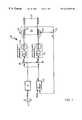
- FIG. 1is a schematic illustration of the controller for straight sections of track for a vehicle, the track wheels of which are connected with torque-controlled individual-wheel drive systems that are driven by a controller as a function of speed sensors and the torque specified from the control stand;
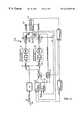
- FIG. 2is a schematic illustration of the controller for curved sections of track for a vehicle, the track wheels of which are connected with torque-controlled individual-wheel drive systems that are actuated by a controller as a function of the curvature and the angular position of the axle;
- FIG. 3is a combination of the control systems in FIG. 1 and FIG. 2, whereby arresting means fix the pivoting axle in position when the curvature is less than a specified value.
- FIG. 1shows a drive coordination control system for straight sections of track 10 , which controls the torque-controlled individual-wheel drive systems 11 and 12 of a railway vehicle 26 .
- the individual-wheel drive systems 11 and 12are connected to track wheels 18 that are opposite each other.
- a differential speed ⁇ nis calculated by a subtraction element 16 .
- a controller 13calculates a control output ⁇ M as a function of a set point. In the ideal case, the set point is zero, but in response to manufacturing tolerances of the individual wheel drive systems 11 and 12 and of the track wheels 18 , it can be adapted to individual conditions as required.
- the differential speed ⁇ ncan be calculated from the speed of the engine.
- the controller 13is designed so that the frequency and the damping of the control output AM can be adjusted dynamically by controller parameters.
- the controller parameterscan be adapted as a function of the speed.
- the controller 13thereby preferably has a proportional section and an integral section, to simulate the dynamic, sine-wave action of a truck with a wheel set axle.
- the controller 13also comprises a differentiating part, the parameter settings of which can be used to adjust the damping of the centering action.
- the torque set points M Set,l M Set,r for the torque-controlled individual wheel drives 11 and 12are calculated from the acceleration torque M Traction requested by the driver and the control output ⁇ M.
- the control output ⁇ Mis added, with respectively different mathematical signs, by a summing element 15 to one-half of the required acceleration torque M Traction .
- the acceleration torque M Tractioncan be set at the driver's control stand 19 .
- FIGS. 2 and 3show an underbody 17 of the vehicle 26 with track wheels 18 which are fastened to a rotationally mounted axle 20 , which preferably represents the rear axle.
- the axle 20is preferably located on a central pivot 28 and can be returned to a specified position by restoring means 24 .
- the front track wheels 23are self-steering and are connected independently of each other with the underbody 17 .
- FIG. 2shows a drive coordination control system 27 for curved sections of track, which is preferably based on the illustrated underbody 17 .
- the angular position ⁇ ? of the axle 20 with respect to the underbody 17is adjusted so that the track wheels are tangential to the rail.
- the angular position ⁇ ? of the axle 20is set by means of the torque set points M Set,l M Set,r of the individual wheel drive systems 11 and 12 .
- the torque set points M Set,l M Set,r for the torque-controlled individual wheel drives 11 and 12are calculated from one-half the acceleration torque M Traction input by the driver, and the control output ⁇ M determined by the controller 21 .
- the control output ⁇ Mis thereby determined by the controller 21 as a function of the curvature ⁇ of the rail as the set point and the angular position ⁇ ? of the axle as the current measured value.
- control output ⁇ Mis thereby added with a positive or negative mathematical sign to the acceleration torque M Traction input by the driver for the respective individual wheel drive 11 or 12 , so that the sum of the two set points ⁇ M* equals zero.
- the curvature ⁇is calculated by dividing the angular velocity ⁇ by the translation velocity v.
- the sine-wave of the set point ⁇ ? of the controller 21is calculated by multiplying the curvature ⁇ by one-half the distance between the curve sensor 22 and the axle 20 to be steered.
- the approximation described hereprevents the rear axle 20 from being steered, although only the forward axle is in the curve.
- the firstimplies that for an exact calculation of the set point at the curve entry, both the curvature on the forward axle and on the rear axle must be known, but on account of the rotation of the truck, only one value in between them is measured.
- the secondis an approximation in the calculation of the steering angle during the curve entry. The two approximations essentially cancel each other out, so that the calculated set point ⁇ ? agrees very well with the ideal steering angle curve.
- the translation velocity vis determined by known means.
- the angular velocity ⁇is preferably calculated by a rotational or gyro sensor.
- the curvature ⁇ of the railis determined by a curve sensor 22 at the wheel position of non-driven forward wheels 23 , which are preferably mounted so that they can rotate individually and are self-steering.
- FIG. 3shows a combination 28 of the drive coordination control system on a straight section and the drive coordination control system on a curved section.
- the curvature ⁇ of the trackis thereby measured continuously, so that it if drops below a specified threshold, the axle 20 must be fixed in position by an arresting means 25 .
- the method described in FIG. 1 for straight tracksis activated. If the measured value exceeds the specified threshold, the arresting means 25 are released, and the method described in FIG. 2 is activated.
- the axle 20is returned to its original position by restoring means, so that it can be arrested in the neutral position.
- the inventionfurther comprises track-guided vehicles that have the drive coordination regulation system described above either for straight sections of track or for curved sections of track, or for both straight and curved sections of track.
Landscapes
- Engineering & Computer Science (AREA)
- Mechanical Engineering (AREA)
- Transportation (AREA)
- Power Engineering (AREA)
- Vehicle Body Suspensions (AREA)
- Steering Control In Accordance With Driving Conditions (AREA)
- Electric Propulsion And Braking For Vehicles (AREA)
Abstract
Description
Claims (24)
Applications Claiming Priority (3)
| Application Number | Priority Date | Filing Date | Title |
|---|---|---|---|
| DE19826452ADE19826452B4 (en) | 1998-06-13 | 1998-06-13 | Method for drive coordination of individual-wheeled, track-guided vehicles |
| DE19826452 | 1998-06-13 | ||
| PCT/EP1999/003699WO1999065752A1 (en) | 1998-06-13 | 1999-05-28 | Method for coordinating the drive of track-guided vehicles with independently driven wheels |
Publications (1)
| Publication Number | Publication Date |
|---|---|
| US6418858B1true US6418858B1 (en) | 2002-07-16 |
Family
ID=7870835
Family Applications (1)
| Application Number | Title | Priority Date | Filing Date |
|---|---|---|---|
| US09/485,577Expired - Fee RelatedUS6418858B1 (en) | 1998-06-13 | 1999-05-28 | Method for drive coordination of rail-guided vehicles with individual-wheel drive |
Country Status (8)
| Country | Link |
|---|---|
| US (1) | US6418858B1 (en) |
| EP (1) | EP1003662B1 (en) |
| DE (2) | DE19826452B4 (en) |
| HU (1) | HU225653B1 (en) |
| IL (1) | IL134495A (en) |
| NO (1) | NO322955B1 (en) |
| PL (1) | PL337850A1 (en) |
| WO (1) | WO1999065752A1 (en) |
Cited By (7)
| Publication number | Priority date | Publication date | Assignee | Title |
|---|---|---|---|---|
| US20050081739A1 (en)* | 2003-09-10 | 2005-04-21 | Ulrich Foesel | Diesel-electric locomotive |
| US20090276107A1 (en)* | 2006-05-31 | 2009-11-05 | Bombardier Transportation Gmbh | Method for controlling an active running gear of a rail vehicle |
| US20110067596A1 (en)* | 2009-09-24 | 2011-03-24 | Siemens Aktiengesellschaft | Rail vehicle with individual wheel drives |
| CN105073482A (en)* | 2013-03-12 | 2015-11-18 | 西门子公司 | Asymmetric drive of rail vehicles with longitudinal wheel sets |
| JP2018144543A (en)* | 2017-03-02 | 2018-09-20 | 公益財団法人鉄道総合技術研究所 | Railway vehicle steering mechanism |
| GB2566715A (en)* | 2017-09-22 | 2019-03-27 | Bombardier Transp Gmbh | Running gear with a steering actuator, associated rail vehicle and control method |
| CN119163713A (en)* | 2024-11-21 | 2024-12-20 | 成都大学 | A gear setting method for an external ADS valve type damping adjustable anti-snaking shock absorber |
Families Citing this family (5)
| Publication number | Priority date | Publication date | Assignee | Title |
|---|---|---|---|---|
| JP2001001896A (en)* | 1999-06-22 | 2001-01-09 | Mitsubishi Heavy Ind Ltd | Single-axle independent wheel bogie for rolling stock |
| AT504539A1 (en) | 2004-06-24 | 2008-06-15 | Siemens Transportation Systems | METHOD FOR MINIMIZING THE WHEEL WEAR OF A RAIL VEHICLE |
| DE102010021352B4 (en)* | 2010-05-22 | 2015-11-26 | Audi Ag | Drive device for a motor vehicle |
| DE102010021996A1 (en) | 2010-05-29 | 2011-12-01 | Audi Ag | Method for operating two drives and motor vehicle with two drives that work on mutually decoupled wheels |
| AT511440B1 (en)* | 2011-08-12 | 2012-12-15 | Traktionssysteme Austria Gmbh | METHOD FOR REGULATING A DRIVE UNIT FOR RAIL VEHICLES AND RAIL VEHICLE DRIVE UNIT |
Citations (19)
| Publication number | Priority date | Publication date | Assignee | Title |
|---|---|---|---|---|
| US2788518A (en)* | 1954-03-03 | 1957-04-09 | Fredrick B Burns | Differential speed detection |
| US3898937A (en)* | 1973-11-19 | 1975-08-12 | Gen Motors Corp | Wheel slip sensing and control system |
| US3937152A (en)* | 1973-03-09 | 1976-02-10 | Allmanna Svenska Elektriska Aktiebolaget | Oscillation sensitive vehicle motor control |
| US4041283A (en)* | 1975-07-25 | 1977-08-09 | Halliburton Company | Railway train control simulator and method |
| US4042810A (en)* | 1975-01-25 | 1977-08-16 | Halliburton Company | Method and apparatus for facilitating control of a railway train |
| US4118774A (en)* | 1977-05-16 | 1978-10-03 | Westinghouse Air Brake Company | Locomotive speed control apparatus |
| US4136303A (en)* | 1976-07-15 | 1979-01-23 | Asea Aktiebolag | Torque limiting drive with slip monitor |
| US4264851A (en)* | 1978-08-25 | 1981-04-28 | Albaret S.A. | System for controlling the direction and speed of a steerable locomotive |
| DE3635804A1 (en) | 1986-10-17 | 1988-05-05 | Peter Dipl Ing Thevis | Automatic steering control for a track-bound vehicle with pivotable wheels |
| US4976332A (en)* | 1987-08-19 | 1990-12-11 | Mannesmann Rexroth Gmbh | Circuit arrangement for the drive of a vehicle |
| DE4037626A1 (en) | 1990-11-27 | 1992-06-04 | Abb Patent Gmbh | Motion regulation between rail vehicles with separate drives - measuring variation in average speed and compensating for longitudinal oscillation between coupled vehicles accordingly |
| DE4114860C1 (en) | 1991-05-07 | 1992-06-17 | Bochumer Eisenhuette Heintzmann Gmbh & Co Kg, 4630 Bochum, De | Railed vehicle drive using digital track guidance - uses opto-electric triangulation sensor pair comprising transmitter and receiver using laser measuring beams |
| EP0557892A2 (en) | 1992-02-24 | 1993-09-01 | FIAT FERROVIARIA S.p.A. | A motorized bogie for a rail vehicle |
| US5392716A (en)* | 1993-07-28 | 1995-02-28 | General Electric Company | Locomotive traction motor control system |
| US5416707A (en) | 1992-09-29 | 1995-05-16 | Siemens Aktiengesellschaft | Method and apparatus for eliminating an inclination of a wheel-block bogie or undercarriage |
| US5740547A (en)* | 1996-02-20 | 1998-04-14 | Westinghouse Air Brake Company | Rail navigation system |
| US6025687A (en)* | 1997-09-26 | 2000-02-15 | Minolta Co., Ltd. | Mobile unit and controller for mobile unit |
| US6161064A (en)* | 1996-12-04 | 2000-12-12 | Abb Daimler-Benz Transportation (Technology) Gmbh | Method of influencing the inflection angle of railway vehicle wagons, and railway vehicle for carrying out this method |
| US6163116A (en)* | 1997-03-10 | 2000-12-19 | Convolve, Inc. | Method and apparatus for the control of gantry machines |
Family Cites Families (7)
| Publication number | Priority date | Publication date | Assignee | Title |
|---|---|---|---|---|
| DE3345260C2 (en)* | 1983-12-14 | 1996-04-11 | Magnet Motor Gmbh | Electric rail vehicle |
| ES2077389T3 (en)* | 1991-04-30 | 1995-11-16 | Sgp Verkehrstechnik | PROCEDURE FOR THE CONTROL OF A ROLLING MECHANISM WITHOUT RIGID AXIAL UNIONS. |
| DE4135691C2 (en)* | 1991-10-25 | 1998-04-16 | Aeg Westinghouse Transport | Arrangement for driving and braking control of vehicles that are equipped with several single wheel drive and braking modules |
| ATE129674T1 (en)* | 1992-09-29 | 1995-11-15 | Siemens Ag | METHOD AND DEVICE FOR CORRECTING AN INLET OF A WHEEL BLOCK BOGIE. |
| ES2071400T3 (en)* | 1992-09-29 | 1995-06-16 | Siemens Ag | PROCEDURE AND DEVICE FOR IMPROVING THE RUNNING PROPERTY OF A ROTARY WHEELLOCK FRAME. |
| DE19538379C1 (en)* | 1995-10-14 | 1997-01-02 | Daimler Benz Ag | Two-wheeled running gear for rail vehicle |
| DE19540089A1 (en)* | 1995-10-27 | 1997-04-30 | Linke Hofmann Busch | Procedure for guiding vehicles according to the zero-level concept |
- 1998
- 1998-06-13DEDE19826452Apatent/DE19826452B4/ennot_activeExpired - Fee Related
- 1999
- 1999-05-28WOPCT/EP1999/003699patent/WO1999065752A1/enactiveIP Right Grant
- 1999-05-28EPEP99926459Apatent/EP1003662B1/ennot_activeExpired - Lifetime
- 1999-05-28PLPL99337850Apatent/PL337850A1/enunknown
- 1999-05-28DEDE59911898Tpatent/DE59911898D1/ennot_activeExpired - Lifetime
- 1999-05-28USUS09/485,577patent/US6418858B1/ennot_activeExpired - Fee Related
- 1999-05-28ILIL13449599Apatent/IL134495A/enactiveIP Right Grant
- 1999-05-28HUHU0002506Apatent/HU225653B1/ennot_activeIP Right Cessation
- 2000
- 2000-02-01NONO20000517Apatent/NO322955B1/ennot_activeIP Right Cessation
Patent Citations (19)
| Publication number | Priority date | Publication date | Assignee | Title |
|---|---|---|---|---|
| US2788518A (en)* | 1954-03-03 | 1957-04-09 | Fredrick B Burns | Differential speed detection |
| US3937152A (en)* | 1973-03-09 | 1976-02-10 | Allmanna Svenska Elektriska Aktiebolaget | Oscillation sensitive vehicle motor control |
| US3898937A (en)* | 1973-11-19 | 1975-08-12 | Gen Motors Corp | Wheel slip sensing and control system |
| US4042810A (en)* | 1975-01-25 | 1977-08-16 | Halliburton Company | Method and apparatus for facilitating control of a railway train |
| US4041283A (en)* | 1975-07-25 | 1977-08-09 | Halliburton Company | Railway train control simulator and method |
| US4136303A (en)* | 1976-07-15 | 1979-01-23 | Asea Aktiebolag | Torque limiting drive with slip monitor |
| US4118774A (en)* | 1977-05-16 | 1978-10-03 | Westinghouse Air Brake Company | Locomotive speed control apparatus |
| US4264851A (en)* | 1978-08-25 | 1981-04-28 | Albaret S.A. | System for controlling the direction and speed of a steerable locomotive |
| DE3635804A1 (en) | 1986-10-17 | 1988-05-05 | Peter Dipl Ing Thevis | Automatic steering control for a track-bound vehicle with pivotable wheels |
| US4976332A (en)* | 1987-08-19 | 1990-12-11 | Mannesmann Rexroth Gmbh | Circuit arrangement for the drive of a vehicle |
| DE4037626A1 (en) | 1990-11-27 | 1992-06-04 | Abb Patent Gmbh | Motion regulation between rail vehicles with separate drives - measuring variation in average speed and compensating for longitudinal oscillation between coupled vehicles accordingly |
| DE4114860C1 (en) | 1991-05-07 | 1992-06-17 | Bochumer Eisenhuette Heintzmann Gmbh & Co Kg, 4630 Bochum, De | Railed vehicle drive using digital track guidance - uses opto-electric triangulation sensor pair comprising transmitter and receiver using laser measuring beams |
| EP0557892A2 (en) | 1992-02-24 | 1993-09-01 | FIAT FERROVIARIA S.p.A. | A motorized bogie for a rail vehicle |
| US5416707A (en) | 1992-09-29 | 1995-05-16 | Siemens Aktiengesellschaft | Method and apparatus for eliminating an inclination of a wheel-block bogie or undercarriage |
| US5392716A (en)* | 1993-07-28 | 1995-02-28 | General Electric Company | Locomotive traction motor control system |
| US5740547A (en)* | 1996-02-20 | 1998-04-14 | Westinghouse Air Brake Company | Rail navigation system |
| US6161064A (en)* | 1996-12-04 | 2000-12-12 | Abb Daimler-Benz Transportation (Technology) Gmbh | Method of influencing the inflection angle of railway vehicle wagons, and railway vehicle for carrying out this method |
| US6163116A (en)* | 1997-03-10 | 2000-12-19 | Convolve, Inc. | Method and apparatus for the control of gantry machines |
| US6025687A (en)* | 1997-09-26 | 2000-02-15 | Minolta Co., Ltd. | Mobile unit and controller for mobile unit |
Cited By (12)
| Publication number | Priority date | Publication date | Assignee | Title |
|---|---|---|---|---|
| US20050081739A1 (en)* | 2003-09-10 | 2005-04-21 | Ulrich Foesel | Diesel-electric locomotive |
| US7401558B2 (en)* | 2003-09-10 | 2008-07-22 | Siemens Aktiengesellschaft | Diesel-electric locomotive |
| US20090276107A1 (en)* | 2006-05-31 | 2009-11-05 | Bombardier Transportation Gmbh | Method for controlling an active running gear of a rail vehicle |
| US8249776B2 (en) | 2006-05-31 | 2012-08-21 | Bombardier Transportation Gmbh | Method for controlling an active running gear of a rail vehicle |
| US20110067596A1 (en)* | 2009-09-24 | 2011-03-24 | Siemens Aktiengesellschaft | Rail vehicle with individual wheel drives |
| US8622002B2 (en)* | 2009-09-24 | 2014-01-07 | Siemens Aktiengesellschaft | Rail vehicle with individual wheel drives |
| CN105073482A (en)* | 2013-03-12 | 2015-11-18 | 西门子公司 | Asymmetric drive of rail vehicles with longitudinal wheel sets |
| CN105073482B (en)* | 2013-03-12 | 2018-07-20 | 西门子公司 | Asymmetric drive of rail vehicles with longitudinal wheel sets |
| JP2018144543A (en)* | 2017-03-02 | 2018-09-20 | 公益財団法人鉄道総合技術研究所 | Railway vehicle steering mechanism |
| GB2566715A (en)* | 2017-09-22 | 2019-03-27 | Bombardier Transp Gmbh | Running gear with a steering actuator, associated rail vehicle and control method |
| GB2566715B (en)* | 2017-09-22 | 2020-05-20 | Bombardier Transp Gmbh | Rail vehicle provided with running gear with a steering actuator and associated control method |
| CN119163713A (en)* | 2024-11-21 | 2024-12-20 | 成都大学 | A gear setting method for an external ADS valve type damping adjustable anti-snaking shock absorber |
Also Published As
| Publication number | Publication date |
|---|---|
| PL337850A1 (en) | 2000-09-11 |
| NO20000517L (en) | 2000-02-01 |
| DE19826452B4 (en) | 2004-03-25 |
| DE59911898D1 (en) | 2005-05-19 |
| NO322955B1 (en) | 2006-12-18 |
| EP1003662A1 (en) | 2000-05-31 |
| EP1003662B1 (en) | 2005-04-13 |
| HUP0002506A2 (en) | 2000-12-28 |
| IL134495A0 (en) | 2001-04-30 |
| NO20000517D0 (en) | 2000-02-01 |
| HU225653B1 (en) | 2007-05-29 |
| IL134495A (en) | 2003-12-10 |
| HUP0002506A3 (en) | 2002-01-28 |
| DE19826452A1 (en) | 1999-12-23 |
| WO1999065752A1 (en) | 1999-12-23 |
Similar Documents
| Publication | Publication Date | Title |
|---|---|---|
| KR101084157B1 (en) | Active steering control device and method for rolling stock | |
| JP4568302B2 (en) | Vehicle longitudinal acceleration control apparatus using jerk information | |
| CN103057546B (en) | Vehicle control apparatus and control method for vehicle | |
| US6418858B1 (en) | Method for drive coordination of rail-guided vehicles with individual-wheel drive | |
| US20090088917A1 (en) | Steering arrangement for a driverless vehicle | |
| CN109606133A (en) | Torque vector control method for distributed drive electric vehicle based on double-layer control | |
| JP6502084B2 (en) | Vehicle control system in case of single wheel failure of four-wheel independent drive vehicle | |
| CN110799409B (en) | Steer-by-wire system with torque vectoring and integrated antiskid control | |
| WO2018072648A1 (en) | Method for controlling stability of rubber-tired train at high speed | |
| CN113147735B (en) | Differential braking/driving coordination rollover prevention control system and control method thereof | |
| CN115416661A (en) | Vehicle auxiliary over-bending method and device, storage medium and electronic device | |
| US6571178B1 (en) | Method for curve recognition and axle alignment in rail vehicles | |
| KR20210106229A (en) | Control method of individual braking system for independently rotating wheel type railway vehicles, and braking system for independently rotating wheel type railway vehicles | |
| EP1063143A1 (en) | Single axle and independent wheels bogie for a railway vehicle | |
| US5442265A (en) | Method and apparatus for improving the running characteristics of a wheel block bogie | |
| JP2000050421A (en) | Electric car | |
| JP3176247B2 (en) | Independent wheel powered bogie for railway vehicles | |
| JP5013634B2 (en) | Independent wheel bogie for railway vehicles and its control method | |
| JP2006182050A (en) | Braking / driving force control device for four-wheel independent drive vehicle | |
| KR20100120572A (en) | Rear wheel steering method of multi-articulated vehicle | |
| JP2000309270A (en) | Fail-safe mechanism for single axle independent wheel truck | |
| US5416707A (en) | Method and apparatus for eliminating an inclination of a wheel-block bogie or undercarriage | |
| JP2014204542A (en) | Vehicular drive control device | |
| CN115384509A (en) | Vehicle auxiliary bending system | |
| JP2014192932A (en) | Motor controlling device for each wheel in cart in which each wheel is driven independently |
Legal Events
| Date | Code | Title | Description |
|---|---|---|---|
| AS | Assignment | Owner name:DAIMLERCHRYSLER AG, GERMANY Free format text:ASSIGNMENT OF ASSIGNORS INTEREST;ASSIGNOR:KOCH, MARKUS;REEL/FRAME:010813/0323 Effective date:20000111 Owner name:DAIMLERCHRYSLER AG, GERMANY Free format text:ASSIGNMENT OF ASSIGNORS INTEREST;ASSIGNOR:OTT, NORBERT;REEL/FRAME:010813/0331 Effective date:20000117 Owner name:DAIMLERCHRYSLER AG, GERMANY Free format text:ASSIGNMENT OF ASSIGNORS INTEREST;ASSIGNOR:KROUZILEK, ROLF;REEL/FRAME:010813/0341 Effective date:20000125 Owner name:DAIMLERCHRYSLER AG, GERMANY Free format text:ASSIGNMENT OF ASSIGNORS INTEREST;ASSIGNOR:HENTSCHEL, FRANK;REEL/FRAME:010813/0366 Effective date:20000113 | |
| FEPP | Fee payment procedure | Free format text:PAYOR NUMBER ASSIGNED (ORIGINAL EVENT CODE: ASPN); ENTITY STATUS OF PATENT OWNER: LARGE ENTITY | |
| REMI | Maintenance fee reminder mailed | ||
| LAPS | Lapse for failure to pay maintenance fees | ||
| STCH | Information on status: patent discontinuation | Free format text:PATENT EXPIRED DUE TO NONPAYMENT OF MAINTENANCE FEES UNDER 37 CFR 1.362 | |
| FP | Lapsed due to failure to pay maintenance fee | Effective date:20060716 |