US6418633B1 - Vertical in-line bow sight - Google Patents
Vertical in-line bow sightDownload PDFInfo
- Publication number
- US6418633B1 US6418633B1US09/607,243US60724300AUS6418633B1US 6418633 B1US6418633 B1US 6418633B1US 60724300 AUS60724300 AUS 60724300AUS 6418633 B1US6418633 B1US 6418633B1
- Authority
- US
- United States
- Prior art keywords
- bow
- sight
- vertical
- support structure
- bow sight
- Prior art date
- Legal status (The legal status is an assumption and is not a legal conclusion. Google has not performed a legal analysis and makes no representation as to the accuracy of the status listed.)
- Expired - Lifetime
Links
- 239000004606Fillers/ExtendersSubstances0.000claimsdescription14
- 229910001369BrassInorganic materials0.000claimsdescription6
- 239000010951brassSubstances0.000claimsdescription6
- 239000000835fiberSubstances0.000description11
- 239000000463materialSubstances0.000description7
- VVQNEPGJFQJSBK-UHFFFAOYSA-NMethyl methacrylateChemical compoundCOC(=O)C(C)=CVVQNEPGJFQJSBK-UHFFFAOYSA-N0.000description3
- 229920005372Plexiglas®Polymers0.000description3
- XAGFODPZIPBFFR-UHFFFAOYSA-NaluminiumChemical compound[Al]XAGFODPZIPBFFR-UHFFFAOYSA-N0.000description3
- 229910052782aluminiumInorganic materials0.000description3
- 244000144985peepSpecies0.000description2
- 229920002972Acrylic fiberPolymers0.000description1
- NIXOWILDQLNWCW-UHFFFAOYSA-Nacrylic acid groupChemical groupC(C=C)(=O)ONIXOWILDQLNWCW-UHFFFAOYSA-N0.000description1
- 230000009471actionEffects0.000description1
- 230000008901benefitEffects0.000description1
- 230000003993interactionEffects0.000description1
- 230000007246mechanismEffects0.000description1
- 230000004048modificationEffects0.000description1
- 238000012986modificationMethods0.000description1
- 229920003023plasticPolymers0.000description1
- 239000004033plasticSubstances0.000description1
Images


Classifications
- F—MECHANICAL ENGINEERING; LIGHTING; HEATING; WEAPONS; BLASTING
- F41—WEAPONS
- F41G—WEAPON SIGHTS; AIMING
- F41G1/00—Sighting devices
- F41G1/46—Sighting devices for particular applications
- F41G1/467—Sighting devices for particular applications for bows
Definitions
- the inventionrelates to a sight for a bow.
- the bow sightincludes vertical sight points.
- the inventionalso relates to vertical sight points that are rotationally adjustable for the achievement of vertical alignment despite the amount of bow torque applied by the archer to the bow.
- the inventionalso relates to a bow sight including a dampener.
- This inventionrelates generally to the field of archery equipment and more particularly to a novel sighting apparatus for use with an archery bow.
- Bow sightsgenerally have multiple sight points for use in shooting arrows into targets of different distances from the archer. Many bow sights include multiple sight points attached to horizontal pins. Bow sights with horizontal pins are shown in U.S. Pat. Nos. 5,103,568; 5,676,122; and 5,685,081.
- U.S. patentsdisclose bow sights having various other arrangements of sighting points. See, for example, U.S. Pat. Nos. 3,234,651; 4,120,096; 5,086,567; and 5,131,153.
- a bow sighthaving a support structure, and two or more vertically aligned vertical pins connected to the support structure is provided. At least two of the vertical pins include a sight point.
- a bow sighthaving a support structure connected to two or more sight points is provided.
- the two or more sight pointsare rotationally adjustable such that they can be rotated into vertical alignment.
- a bow sighthaving a support structure, a sight point connected to the support structure, and a dampener is provided.
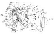
- FIG. 1is a perspective view of a bow sight according to the principles of the present invention.
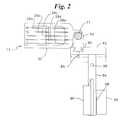
- FIG. 2is a top view of a bow sight according to the principles of the present invention.
- FIG. 3is a front view of a bow sight according to the principles of the present invention.
- FIG. 4is a right side view of a bow sight according to the principles of the present invention.
- FIG. 5is a left side view of a bow sight according to the principles of the present invention.
- FIG. 6is a back view of a bow sight according to the principles of the present invention and including a bow torque indicator.
- FIG. 7is a bottom view of a bow sight according to the principles of the present invention.
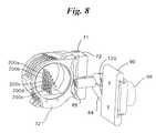
- FIG. 8is a perspective view of an alternate embodiment of a bow sight according to the principles of the present invention.
- FIG. 9is an exploded view of a vertical pin, an associated adjustment knob and an associated cam member according to the principles of the present invention.
- FIGS. 10 a-dare a rear view, front view, left view and right view respectively of a vertical pin according to the principles of the present invention.
- a bow sightis a device that is attached to an archery bow and which provides one or more sight points.
- the archeruses the sight point(s) to aim at the target.
- a peep sightmay be placed on the string of the bow such that the archer can sight through the peep sight and at the sight point with the target in the background.
- FIG. 1shows a preferred embodiment of a bow sight 12 .
- the view of the bow sight as seen from the archer in the shooting positionis referred to as the front view of the bow sight.
- a sighting pointis any shape, point, or indicia of any sort that is visually placed in line with the target to be shot at for assisting in the proper aiming of the bow.
- Sight pointscan be circular shapes, other geometrical shapes, colored dots, the end of a light gathering cable, or simply the end of a sight pin, for example.
- the sight points 20 a-eare formed by the ends of the fiber optic cables 26 a-e .
- the fiber optic cables 26 a-ecollect light along their lengths and the light exits the end of the cables 26 a-e .
- the ends of the fiber optic cables 26 a-eare held in place by vertical pins.
- a vertical pinis a member having a vertically elongated portion, wherein that member supports a sight point and wherein the sight point may be integral with or a separate piece from the vertical pin.
- a vertical pincould include features in addition to the fact that it has a length that is vertical.
- a vertical pincould be an L-shaped pin with the horizontal portion of the L-shape extending in the direction toward the archer in the shooting position. See FIG. 8 for an example of an L-shaped pin that falls within the definition of a vertical pin.
- Vertical pinshave a significant advantage over horizontal pins because the field of view to the right and left of the vertical pins is very open for viewing the target and the environment of the target area.
- the vertical pins 30 a-eare linear vertical pins that define a hole in the uppermost end for receiving the ends of the fiber optic cables 26 a-e.
- the vertical pinsare linear vertical pins that do not define a hole in the uppermost end.
- the ends of the fiber optic cables 26 a-eare glued or crimped to the ends of the vertical pins 30 a-e.
- a support structureis any structural member that supports a sight point.
- the support structure 32is a generally circular shaped piece of acrylic that supports the vertical pins 30 a-e which support the sight points 20 a-e respectively.
- the circular shape of the support structure 32provides protection of the vertical pins 30 a-e from being damaged or bent while also providing a good view of the ultimate target through the interior portion of the circular support structure.
- the point at which a vertical pin is attached to a support structureis the attachment point.
- Vertical pinscan be attached to the support structure in many different orientations. Vertical pins can be attached to the support structure with the sight point below the attachment point or with the sight point above the attachment point. It is also within the scope of the present invention to have a bow sight with one or more vertical pins attached to the support structure with the sight point below the attachment point and one or more vertical pins attached to the support structure with the sight point above the attachment point.
- a vertical pinis “vertically adjustable” when the associated sight point for that vertical pin can be moved vertically up or down.
- each of the vertical pins 30 a-eis vertically adjustable by movement of the entire vertical pin.
- Each of the vertical pins 30 a-einclude gears, such as gears 50 on vertical pin 30 a as shown in FIG. 9 .
- the adjustment knobs 54 a-eeach include gears, such as gears 52 on adjustment knob 54 a as shown in FIG. 9 .
- the gears on vertical pins 30 a-einteract respectively with the gears on the adjustment knobs 54 a-e such that rotation of an adjustment knob results in linear vertical motion of the respective vertical pin.
- the adjustment knobs 54 a-ealso include levers 55 a-e respectively.
- the levers 55 a-eare each integral with the corresponding adjustment knobs 54 a-e . The lever makes it easier to rotate the adjustment knob.
- axis rod 56extends through the center axis of the adjustment knobs 54 a-e .
- the adjustment knobs 54 a-erotate around the axis rod 56 .
- the cam members 57 a-eallow the archer to lock the vertical position of each vertical pin 30 a-e respectively.
- the cam members 57 a-eeach comprise a cam portion 61 a-e that rotates about an axis rod 59 . Rotation of a cam member 57 a-e results in engagement or disengagement of the respective cam portion 61 a-e with the side of the vertical pin opposite the gears 50 . This camming action allows the archer to prevent the vertical pins from moving once their vertical height is properly set.
- the archerrotates the corresponding cam member, makes an adjustment of the vertical height of the pin by rotating the adjustment lever, and then rotates the cam member back into engagement with the vertical pin to hold the new vertical position.
- the cam members 57 a-eaccomplish this purpose by preventing rotation of the adjustment knobs 54 a-e respectively.
- a screwcould be used in place of cam members 57 a-e .
- Such screwswould extend perpendicular to the vertical pins and would extend through a hole in the support structure 32 . Tightening of the screw associated with the vertical pin 30 a , for example, would secure the vertical position of the sight point on vertical pin 30 a . To adjust the height of vertical pin 30 a , the associated screw is loosened and the adjustment knob 55 a rotated.
- the end of a light gathering cableis used as the sight point.
- a light gathering cableis any cable that collects light along the perimeter of its length and projects the light out the end of the cable.
- the light gathering cableis a fiber optic cable.
- Fiber optic cables 26 a-eare mounted around the perimeter of the support structure 32 as shown in FIGS. 1, 2 , 4 , 5 and 7 . As shown in FIG. 7, the fiber optic cables 26 a-e extend within grooves 23 a-e in the vertical pins 30 a-e . The fiber optic cables are bent 45-90 degrees such that the end of the light gathering cables then pass through the holes 62 a-e in the end of the vertical pins 30 a-e respectively. The ends of the fiber optic cables 26 a-e are the sight points in a preferred embodiment.
- Two vertical pinsare “vertically aligned” when they are in a single vertical line as viewed from the position of the archer while holding the bow in the shooting position (with the string drawn). Vertical pins that do not form a single line as viewed from the archer, but that through an adjustment can be brought into a single line from the view of the archer still fall within the definition of “vertically aligned”.
- all five vertical pins 26 a-eare vertically aligned. While the vertical pins 26 a-e may not initially form a single line as viewed from the archer in the shooting position, the bow sight can be adjusted to bring the five pins 26 a-e into a single line as viewed from the archer in the shooting position as will be described below.
- the bow torque adjustment featureis embodied in the ability to rotate the support structure 32 about a vertical axis 70 .
- This bow torque adjustment featureallows for adjustment of bow torque to ensure vertical alignment of the vertical pins 30 a-e .
- an archercan set the bow sight 12 such that when that archer shoots the bow the vertical pins 30 a-e all appear in a single line as viewed from the archer when shooting the bow.
- the support structure 32includes an upper sleeved arm 74 and a lower sleeved arm 76 .
- Sleeve member 72is rotationally connected to the support structure 32 along axis 70 by torque adjustment screw 71 and a torque adjustment screw 73 which both extend linearly along the vertical axis 70 .
- An archercan loosen both torque adjustment screws 71 and 73 with an alien wrench (or by other means depending on the type of screw used) and then make the rotational adjustment between the sleeve member 72 and the support structure 32 as is necessary to bring the vertical pins 30 a-e into vertical alignment in the shooting position. Once the correct rotational position is achieved, the torque adjustment screws 71 and 73 are tightened to prevent the sleeve member 72 and support structure 32 from rotating relative to one another.
- FIG. 6is a rear view of a bow sight according to the principles of the present invention.
- FIG. 6includes a bow torque indicator 77 (not shown on the other drawings).
- a bow torque indicatoris any vertical member that indicates to the archer whether there is bow torque.
- the bow torque indicatoris a vertical wire 79 situated behind the vertical pins 30 a-e .
- the vertical wire 79is aircraft cable with a diameter of 0.030 inches. The vertical wire 79 is attached to the support structure by screws 81 and 83 .
- the sleeve member 72includes a double dove tail portion 80 that is received by a double dove tail recess in horizontal bar 82 .
- a screw 85allows for tightening and loosening of the sliding interaction between the double dove tail 80 and the double dove tail recess in the horizontal bar 82 .
- the vertical position of the sleeve member 72can therefore be adjusted relative to the horizontal bar 82 .
- the horizontal bar 82is received by an extender member 84 that has one end with an adjustable jaw 86 for holding and supporting the horizontal bar 82 .
- the jaw 86is adjustable via the screw 88 .
- the horizontal bar 82can be positionally adjusted horizontally from left to right as viewed from the archer in the shooting position.
- the extender member 84is releasably and adjustably connected to base 90 . As shown in FIG. 6, extender 84 has a double dove tail 92 that is received by the double dove tail recess 94 of the base 90 . Therefore, extender 84 is slidably received by the base 90 such that the base 90 and the extender 84 can be horizontally moved relative to one another toward and away from the archer.
- the extender 84is nonslidably secured to the base 90 by screw 96 having adjustment knob 98 .
- the adjustment knob 98By tightening the adjustment knob 98 , the screw 96 extends into a small recess (not shown) in the base 90 to prevent sliding movement between the extender 84 and the base 90 .
- the base 90is secured to the bow with two screws that pass through holes 100 and 102 and into the bow (see FIG. 5 ).
- dampenersare provided on the bow site.
- a dampeneris any device which includes at least some material that is softer than the material that makes up the part of the bow sight to which the device is directly attached, such that the device at least partially absorbs the vibrations caused by the release of the bow string when shooting an arrow. Dampeners may be placed in the support structure itself or in any of the various members that connect the support structure to the bow.
- a dampener 120is secured in a recess 122 in the extender 84 .
- the recess 122 and the dampener 120are oval in shape but could be any shape.
- the dampener 120comprises a brass core 124 surrounded by a webbed rubber member 126 around the perimeter of the brass core 124 .
- Alternate materialscan certainly be used for the dampener.
- the corecould be aluminum with an outer perimeter material of plastic.
- dampener 130is secured in a recess 132 in the adjustment knob 98 .
- the dampener 130 and recess 132 in this embodimentare circular in shape but again could be any shape.
- the dampener 130includes a brass core 134 and a webbed rubber member 136 around the perimeter of the brass core 134 .
- dampeners 120 and 130 connected to the support structure 32may be connected to the support structure 32 in many different locations.
- a dampenercould be set in a recess (not shown) in the support structure 32 .
- FIG. 8is a perspective view of an alternative embodiment of the resent invention.
- the difference between FIG. 1 and FIG. 8is that the vertical pins 200 a-e in FIG. 8 are L-shaped. That is, the vertical pins 200 a-e have a vertical portion and also a horizontal portion. The horizontal portion extends in the direction towards the archer when the archer is standing in the shooting position.
- the sight points 202 a-e associated respectively with the vertical pins 200 a-eare all in the same vertical plane.
- FIGS. 10 a-dshow a preferred embodiment of a vertical pin 30 a from the rear, front, left and right views respectively.
- the fiber optic cable 26 acan also be seen in its relationship to the vertical pin 30 a.
- the vertical pins 10 a-eare protected by a circular and planar piece of non-opaque plexiglass.
- the plexiglass(not shown) fits within the rim 11 of the support structure 32 (see FIG. 1 ).
- a similar piece of plexiglassmay be placed on the back side of the support structure 32 .
- the vertical pins, pin height adjustment levers, cam lock mechanisms and the support structureare made of acrylic plastic. It should be appreciated, however, that this invention is not limited by the type of material used for its parts. Many alternative materials can be used. For example, in an alternative embodiment these parts could be made of aluminum or any other material that can structurally perform the functions of these parts.
- the sleeve member 72 , horizontal bar 82 , extender 84 , base 90 , and adjustment knob 98are made of aluminum.
Landscapes
- Physics & Mathematics (AREA)
- Optics & Photonics (AREA)
- Engineering & Computer Science (AREA)
- General Engineering & Computer Science (AREA)
- Mechanical Control Devices (AREA)
- Catching Or Destruction (AREA)
- Conveying And Assembling Of Building Elements In Situ (AREA)
- Sampling And Sample Adjustment (AREA)
Abstract
Description
Claims (33)
Priority Applications (7)
| Application Number | Priority Date | Filing Date | Title |
|---|---|---|---|
| US09/607,243US6418633B1 (en) | 2000-06-30 | 2000-06-30 | Vertical in-line bow sight |
| US10/196,333US6892462B2 (en) | 2000-06-30 | 2002-07-16 | Vertical in-line bow sight |
| US10/406,733US7036234B2 (en) | 2000-06-30 | 2003-04-03 | Bow sight having vertical, in-line sight pins, and methods |
| US10/639,189US7159325B2 (en) | 2000-06-30 | 2003-08-11 | Bow sight with fiber optics |
| US11/541,477US7343686B2 (en) | 2000-06-30 | 2006-09-29 | Bow sight with fiber optics |
| US12/021,556US7549230B2 (en) | 2000-06-30 | 2008-01-29 | Bow sight with fiber optics |
| US12/465,788US20090235540A1 (en) | 2000-06-30 | 2009-05-14 | Bow sight with fiber optics |
Applications Claiming Priority (1)
| Application Number | Priority Date | Filing Date | Title |
|---|---|---|---|
| US09/607,243US6418633B1 (en) | 2000-06-30 | 2000-06-30 | Vertical in-line bow sight |
Related Child Applications (2)
| Application Number | Title | Priority Date | Filing Date |
|---|---|---|---|
| US10/196,333ContinuationUS6892462B2 (en) | 2000-06-30 | 2002-07-16 | Vertical in-line bow sight |
| US10/196,333Continuation-In-PartUS6892462B2 (en) | 2000-06-30 | 2002-07-16 | Vertical in-line bow sight |
Publications (1)
| Publication Number | Publication Date |
|---|---|
| US6418633B1true US6418633B1 (en) | 2002-07-16 |
Family
ID=24431429
Family Applications (6)
| Application Number | Title | Priority Date | Filing Date |
|---|---|---|---|
| US09/607,243Expired - LifetimeUS6418633B1 (en) | 2000-06-30 | 2000-06-30 | Vertical in-line bow sight |
| US10/196,333Expired - LifetimeUS6892462B2 (en) | 2000-06-30 | 2002-07-16 | Vertical in-line bow sight |
| US10/639,189Expired - LifetimeUS7159325B2 (en) | 2000-06-30 | 2003-08-11 | Bow sight with fiber optics |
| US11/541,477Expired - LifetimeUS7343686B2 (en) | 2000-06-30 | 2006-09-29 | Bow sight with fiber optics |
| US12/021,556Expired - Fee RelatedUS7549230B2 (en) | 2000-06-30 | 2008-01-29 | Bow sight with fiber optics |
| US12/465,788AbandonedUS20090235540A1 (en) | 2000-06-30 | 2009-05-14 | Bow sight with fiber optics |
Family Applications After (5)
| Application Number | Title | Priority Date | Filing Date |
|---|---|---|---|
| US10/196,333Expired - LifetimeUS6892462B2 (en) | 2000-06-30 | 2002-07-16 | Vertical in-line bow sight |
| US10/639,189Expired - LifetimeUS7159325B2 (en) | 2000-06-30 | 2003-08-11 | Bow sight with fiber optics |
| US11/541,477Expired - LifetimeUS7343686B2 (en) | 2000-06-30 | 2006-09-29 | Bow sight with fiber optics |
| US12/021,556Expired - Fee RelatedUS7549230B2 (en) | 2000-06-30 | 2008-01-29 | Bow sight with fiber optics |
| US12/465,788AbandonedUS20090235540A1 (en) | 2000-06-30 | 2009-05-14 | Bow sight with fiber optics |
Country Status (1)
| Country | Link |
|---|---|
| US (6) | US6418633B1 (en) |
Cited By (55)
| Publication number | Priority date | Publication date | Assignee | Title |
|---|---|---|---|---|
| US6508005B2 (en)* | 2000-01-26 | 2003-01-21 | Copper John Corporation | Solo plane pin head bow sight |
| US6560884B1 (en)* | 2001-11-20 | 2003-05-13 | Abbas Ben Afshari | Fixed pin bow sight |
| US6601308B2 (en)* | 2002-01-02 | 2003-08-05 | Bahram Khoshnood | Ambient light collecting bow sight |
| US6618949B1 (en)* | 2002-04-09 | 2003-09-16 | Shawn D. Keener | System and method for adjusting sighting pins in an archery sight and determining the velocity of an arrow |
| US6634111B2 (en)* | 2000-10-13 | 2003-10-21 | Tru-Glo, Inc. | Multiple pin sight for an archery bow |
| US20030208916A1 (en)* | 2000-06-30 | 2003-11-13 | Rager Christopher A. | Bow sight having vertical, in-line sight pins, and methods |
| US20040006879A1 (en)* | 2001-11-20 | 2004-01-15 | Afshari Abbas Ben | Bow sight with vertically aligned pins |
| US20040031162A1 (en)* | 2000-06-30 | 2004-02-19 | Trophy Ridge, Llc | Bow sight with fiber optics |
| USD487789S1 (en) | 2000-06-30 | 2004-03-23 | Trophy Ridge, Llc | Bow sight |
| US20040111900A1 (en)* | 2002-09-13 | 2004-06-17 | Rager Christopher A. | Pendulum bow sight having vertical pins |
| US6802129B1 (en)* | 2002-09-06 | 2004-10-12 | Wirth Reinhold F | Archery sight, an optic assembly, and optic adjustment mechanisms for use in an archery sight |
| US20040244211A1 (en)* | 2001-01-26 | 2004-12-09 | Afshari Abbas Ben | Illuminated sight pin |
| US20050138824A1 (en)* | 2003-12-24 | 2005-06-30 | Afshari Abbas B. | Fiber optic sight pin |
| US20050150119A1 (en)* | 2004-01-13 | 2005-07-14 | Montana Black Gold | Sight and sight pins for archery bow |
| US20050183272A1 (en)* | 2004-02-24 | 2005-08-25 | B.E.M., Inc. | Archery bow sight |
| US20050235503A1 (en)* | 2004-04-23 | 2005-10-27 | Afshari Abbas B | Fiber optic indicator marking for bow sight |
| US20050241163A1 (en)* | 2004-04-28 | 2005-11-03 | Algurt Cudney | Sight for armament |
| US20050246909A1 (en)* | 2002-09-13 | 2005-11-10 | Rager Christopher A | Pendulum bow sight |
| US20060005406A1 (en)* | 2001-11-20 | 2006-01-12 | Afshari Abbas B | Bow sight with vertically aligned pins |
| US20060096150A1 (en)* | 2004-11-11 | 2006-05-11 | Carolina Archery Products Inc. | Products and processes for archery and firearm sights |
| USD522083S1 (en) | 2004-04-23 | 2006-05-30 | Abbas Ben Afshari | Bow sight pin |
| US20060150429A1 (en)* | 2005-01-13 | 2006-07-13 | Bahram Khoshnood | Ambient light collecting sight pin for a bow sight |
| USD528183S1 (en)* | 2004-12-29 | 2006-09-12 | Trophy Taker, Inc. | Archery sighting device |
| US7103981B1 (en) | 2003-12-01 | 2006-09-12 | Trophy Ridge, Llc | Bow sight with injection molded metal sight pins, and methods |
| USD530773S1 (en)* | 2004-12-29 | 2006-10-24 | Trophy Taker, Inc. | Archery sighting device |
| US20060254065A1 (en)* | 2005-05-12 | 2006-11-16 | Grace Nathaniel E | Archery bow sight |
| US20060283028A1 (en)* | 2001-11-20 | 2006-12-21 | Afshari Abbas B | Bow sight with angled pins |
| US20070062052A1 (en)* | 2005-09-14 | 2007-03-22 | Smith Jon C | Arrow-mounted sight |
| USD543603S1 (en)* | 2006-05-11 | 2007-05-29 | Bahram Khoshnood | Archery bow sight |
| US7243432B1 (en) | 2004-05-28 | 2007-07-17 | Bear Archery, Inc. | Pendulum bow sight having a vertical pin |
| US20070220761A1 (en)* | 2006-03-24 | 2007-09-27 | H-T Archery Products, Llc | Archery bow sights and archery bows including same |
| US7275328B1 (en) | 2004-05-28 | 2007-10-02 | Bear Archery, Inc. | Bow sight having vertical positioning mechanism |
| US20070227018A1 (en)* | 2006-03-28 | 2007-10-04 | Montana Black Gold | Bow sight with controlled light intensity sight pin |
| US20080005914A1 (en)* | 2006-07-07 | 2008-01-10 | Abbas Ben Afshari | Bow sight with sighting aperture |
| USD562427S1 (en) | 2005-01-13 | 2008-02-19 | Bahram Khoshnood | Bow sight |
| US20080222904A1 (en)* | 2007-03-14 | 2008-09-18 | Erhard Rory J | Rotating pin sight |
| US20090049734A1 (en)* | 2007-08-22 | 2009-02-26 | Troy Storch | Multiple sight gun sight assembly |
| US20090199418A1 (en)* | 2006-01-27 | 2009-08-13 | Truglo, Inc. | Illuminated Sighting Device |
| US20090278404A1 (en)* | 2008-05-08 | 2009-11-12 | Infineon Technologies Ag | Circuit Arrangement and System for Use in a Motor Vehicle |
| US20100018513A1 (en)* | 2008-07-22 | 2010-01-28 | Scaniffe Michael J | Compound bow accessory |
| US20100024228A1 (en)* | 2008-07-30 | 2010-02-04 | C. S. Gibbs Corporation | Archery Bow Sight and Method |
| USD625377S1 (en)* | 2008-12-09 | 2010-10-12 | Kauffman Nathan C | Combination bow sight and range finder |
| US8245409B2 (en) | 2010-05-04 | 2012-08-21 | Trijicon, Inc. | Bow sight |
| US20130036617A1 (en)* | 2011-08-12 | 2013-02-14 | Hoyt Archery, Inc. | Dual bar adjustable bow sight |
| US8448341B2 (en) | 2010-05-04 | 2013-05-28 | Trijicon, Inc. | Bow-sight mount |
| US20150075016A1 (en)* | 2013-09-17 | 2015-03-19 | Bear Archery, Inc. | Automatic pin adjustment indicator for archery sights |
| US9103631B2 (en) | 2012-03-22 | 2015-08-11 | Trophy Taker, Inc. | Sight for an archery bow |
| US9513085B2 (en) | 2013-07-24 | 2016-12-06 | Bear Archery, Inc. | Automatic pin adjustment for archery sights |
| US20170102210A1 (en)* | 2015-10-13 | 2017-04-13 | Kevin STERN | Device and method for adjusting bow sight at full draw |
| USD823147S1 (en) | 2016-11-21 | 2018-07-17 | Bushnell Inc. | Laser range finder with wind sensor |
| US10288377B2 (en)* | 2017-05-18 | 2019-05-14 | Allen Daniel Stephenson | Alignment aid |
| USD875869S1 (en)* | 2018-05-21 | 2020-02-18 | Shenzhen Ruierxing Electronic Co., Ltd. | Bow sighting device with laser ranging |
| US10697728B2 (en)* | 2016-12-06 | 2020-06-30 | Dale A Morrell | Peep sight for an archery bow |
| US20230332866A1 (en)* | 2020-06-11 | 2023-10-19 | Bear Archery, Inc. | Electronic archery sights |
| USD1061782S1 (en) | 2021-09-02 | 2025-02-11 | Dialed Archery, Llc | Adjustable archery bow sight |
Families Citing this family (30)
| Publication number | Priority date | Publication date | Assignee | Title |
|---|---|---|---|---|
| US8302318B2 (en)* | 2004-12-22 | 2012-11-06 | Saunders Charles A | Aiming system for slingshots and projectile-launching devices |
| US7373723B1 (en)* | 2005-09-07 | 2008-05-20 | Tupper Jr John M | Bow sight |
| US8215024B1 (en) | 2006-04-15 | 2012-07-10 | Michael Terzo | Sighting device for a weapon |
| US7698824B2 (en)* | 2006-05-16 | 2010-04-20 | Wilson Keith W | High performance sights |
| US7578067B2 (en)* | 2007-01-16 | 2009-08-25 | Bear Archery, Inc. | Bow sight structures |
| US7644503B2 (en)* | 2007-11-23 | 2010-01-12 | Kdl Outdoor Products, Inc. | Bow sight |
| US20090293855A1 (en)* | 2008-05-28 | 2009-12-03 | Danielson Lewis A | Aiming Device and Method for Archery Bow |
| US7805847B2 (en)* | 2008-06-13 | 2010-10-05 | Behr Joseph R | Sighting system and range finder for an archery bow |
| US20120085331A1 (en)* | 2008-08-22 | 2012-04-12 | Lang Russell W | Systems and methods of accessory mounting |
| US20100043765A1 (en)* | 2008-08-22 | 2010-02-25 | Lang Russell W | Archery bow accessory mount |
| US8176644B1 (en) | 2008-10-16 | 2012-05-15 | Gregory E. Summers | Producing and using archery sights |
| US8069607B2 (en)* | 2009-06-01 | 2011-12-06 | Marlin Daniel Ballard | Gun sight configured for providing range estimation and/or bullet drop compensation |
| USD621899S1 (en) | 2009-08-03 | 2010-08-17 | Marlin Daniel Ballard | Multi-post gun sight body |
| USD622346S1 (en) | 2009-08-03 | 2010-08-24 | Marlin Daniel Ballard | Multi-post gun sight body |
| USD622803S1 (en) | 2009-08-03 | 2010-08-31 | Marlin Daniel Ballard | Multi-post gun sight body |
| US8661696B2 (en) | 2010-01-08 | 2014-03-04 | Field Logic, Inc. | Eye alignment assembly |
| US8752303B2 (en) | 2010-03-05 | 2014-06-17 | Donald Priebe | Sighting system |
| US8099874B2 (en)* | 2010-03-05 | 2012-01-24 | Donald Priebe | Sighting system |
| US8272137B2 (en)* | 2010-05-06 | 2012-09-25 | Michael Craig Logsdon | Selective fiber optic sight system |
| US8776386B2 (en) | 2011-05-05 | 2014-07-15 | Klint McLean KINGSBURY | Bow sight with light gathering point shaped pins, illuminated yardage indicia, and individual pin micro-adjustment |
| US8826551B2 (en) | 2011-05-18 | 2014-09-09 | Craig Gibson | Special bow sighting improvement known as the revolver |
| US8839525B2 (en)* | 2012-01-06 | 2014-09-23 | Field Logic, Inc. | Pin array adjustment system for multi-axis bow sight |
| US8713807B2 (en)* | 2012-03-16 | 2014-05-06 | Truglo, Inc. | Sighting device with selectable pin lighting |
| USD696742S1 (en) | 2012-07-05 | 2013-12-31 | Matthew J Pientka | Firearm support |
| US9482488B2 (en) | 2014-01-13 | 2016-11-01 | Leupold & Stevens, Inc. | Illuminated reticle system for a riflescope or other aimed optical device |
| CN104089528B (en)* | 2014-07-05 | 2015-10-21 | 宁波海伯精工机械制造有限公司 | The sight of accurate core position can be regulated |
| US9429393B2 (en)* | 2014-12-12 | 2016-08-30 | Hoyt Archery, Inc. | Illuminated archery bow sight apparatus |
| US9869528B2 (en) | 2015-02-05 | 2018-01-16 | Feradyne Outdoors, Llc | Micro-pointer system for archery sights |
| US9638492B2 (en)* | 2015-07-13 | 2017-05-02 | Rene Henry Jones | Electronically illuminated open sight for handguns and rifles |
| US10184757B1 (en) | 2017-07-06 | 2019-01-22 | Garmin Switzerland Gmbh | Positioning device for alignment of archery sight |
Citations (19)
| Publication number | Priority date | Publication date | Assignee | Title |
|---|---|---|---|---|
| US3234651A (en) | 1963-09-24 | 1966-02-15 | Russell C Rivers | Bow sight |
| US3455027A (en)* | 1967-08-30 | 1969-07-15 | David J Perkins | Archery bow sight |
| US3475820A (en)* | 1967-09-27 | 1969-11-04 | George L Kernan | Bow sight |
| US4120096A (en) | 1977-06-13 | 1978-10-17 | Keller Charles R | Bow sight |
| US4244115A (en)* | 1979-06-04 | 1981-01-13 | Alvin Waldorf | Bow sight |
| US4977678A (en) | 1989-06-27 | 1990-12-18 | Benny Sears | Archery sight |
| US5086567A (en) | 1991-04-02 | 1992-02-11 | Tutsch Jerald H | Archery bow sight reticle with multiple fixed aiming points |
| US5103568A (en) | 1986-06-04 | 1992-04-14 | Norman Canoy | Archery sighting device |
| US5131153A (en) | 1991-09-04 | 1992-07-21 | Seales Milford L | Bow sight |
| US5362046A (en) | 1993-05-17 | 1994-11-08 | Steven C. Sims, Inc. | Vibration damping |
| US5383279A (en) | 1994-04-06 | 1995-01-24 | Tami; Mark G. | Sight guard sight |
| US5442861A (en) | 1993-12-23 | 1995-08-22 | Lorocco; Paul M. | Sight pin and holder for archery bow |
| US5442863A (en)* | 1993-12-16 | 1995-08-22 | Fazely; Khosro | Stereoscopic sighting device |
| US5634278A (en) | 1995-09-20 | 1997-06-03 | Tommy E. Hefner | Bow sight |
| US5676122A (en) | 1995-03-10 | 1997-10-14 | Wiseby; Tony | Arrangement for a bow sight |
| US5685081A (en) | 1995-09-08 | 1997-11-11 | Winegar; Mike | Aiming device for use on archery bows |
| US5836294A (en)* | 1997-05-14 | 1998-11-17 | James E. Merritt | Bow sight |
| US5956854A (en) | 1996-12-26 | 1999-09-28 | Tru-Glo, Inc. | Day/night weapon sight |
| US6276068B1 (en)* | 2000-01-26 | 2001-08-21 | Douglas J. Sheliga | Archery sight with zero pin spacing capability |
Family Cites Families (61)
| Publication number | Priority date | Publication date | Assignee | Title |
|---|---|---|---|---|
| US3521362A (en)* | 1968-07-25 | 1970-07-21 | Armond J Duplechin | Archery sight |
| US3641675A (en)* | 1969-07-14 | 1972-02-15 | Buford H Funk Jr | Optical alignment system |
| US3648376A (en)* | 1970-01-13 | 1972-03-14 | William J Millnamow | Bow sight |
| US3945127A (en)* | 1974-03-27 | 1976-03-23 | Spencer Phillip G | Sighting apparatus |
| US3997974A (en) | 1976-01-19 | 1976-12-21 | Larson Marlow W | Archery bow sighting mechanism |
| US4116194A (en)* | 1976-10-18 | 1978-09-26 | Fine-Line, Inc. | Peep sight for archery bow |
| US4162579A (en)* | 1978-05-12 | 1979-07-31 | Wakelf James | Archery sight |
| US4159575A (en)* | 1978-06-05 | 1979-07-03 | Philip Kalmbach | Sighting device for archery bows |
| US4177572A (en)* | 1978-06-28 | 1979-12-11 | Hindes Ted E | Lighted sight pin for archery bows |
| US4418479A (en)* | 1978-09-27 | 1983-12-06 | John Stachnik | Variable range sighting mechanism for use with archery bow |
| US4215484A (en)* | 1978-11-07 | 1980-08-05 | Lauffenburger Robert F | Aiming device for archery bows and other objects |
| US4291664A (en) | 1979-04-30 | 1981-09-29 | Nishioka Jim Z | Projectile shooting guide for bows |
| US4541179A (en)* | 1984-04-24 | 1985-09-17 | Closson Robert A | Sighting device for use on bows |
| US4884347A (en)* | 1988-11-14 | 1989-12-05 | Browning | Bow sight |
| US4928394A (en)* | 1989-04-03 | 1990-05-29 | Sherman James R | Sight for archery bow |
| US5174269A (en)* | 1990-07-30 | 1992-12-29 | Toxonic, Inc. | Archery bow sighting device |
| JP3038596B2 (en)* | 1990-10-24 | 2000-05-08 | 創輝株式会社 | Ship propulsion lifting device |
| US5231765A (en)* | 1992-06-26 | 1993-08-03 | Sherman James R | Illuminated sight having a light collector serving a fiber optic |
| US5285767A (en)* | 1992-09-11 | 1994-02-15 | Robert Padilla | Shock absorption in archery sights |
| US5341791A (en)* | 1993-07-09 | 1994-08-30 | Gary J. Shafer | Bow sight apparatus |
| US5367780A (en)* | 1993-07-30 | 1994-11-29 | Savage; Huey P. | Archery bow torque sight |
| US5517979A (en)* | 1994-01-12 | 1996-05-21 | Closson; Robert A. | Shock absorbing device for bows |
| US5560113A (en)* | 1994-06-27 | 1996-10-01 | New Archery Products Corp. | Bowsight |
| US5579752A (en)* | 1995-03-08 | 1996-12-03 | Ebsa Corporation | Adjustable bow sight |
| US5653034A (en) | 1995-05-24 | 1997-08-05 | Trijicon, Inc. | Reflex sighting device for day and night sighting |
| US5632091A (en)* | 1995-05-30 | 1997-05-27 | Brion; James | Archery bow sight |
| US5619801A (en)* | 1995-06-26 | 1997-04-15 | Toxonics Manufacturing, Inc. | Fiber optic pin sight for a bow |
| US5653217A (en) | 1995-10-04 | 1997-08-05 | Keller; Thomas M. | Bow sight |
| US5644849A (en)* | 1995-11-16 | 1997-07-08 | Toxonigs Manufacturing, Inc. | Bow sight mount for absorbing the forces of shear |
| US5651185A (en) | 1996-02-13 | 1997-07-29 | Vanderheyden; Carl | Archery bow sight |
| US6122833A (en)* | 1996-12-26 | 2000-09-26 | Tru-Glo, Inc. | Day/night weapon sight |
| US5718215A (en)* | 1997-01-03 | 1998-02-17 | Ebsa Corporation | Adjustable bow sight |
| US5996569A (en) | 1997-04-25 | 1999-12-07 | Wilson; Keith W. | Transparent rear bow sight |
| US5862603A (en)* | 1997-07-11 | 1999-01-26 | Ellig; Michael | Sighting indicia |
| US5894672A (en)* | 1997-08-14 | 1999-04-20 | Trumark Manufacturing Company | Enhanced sight marker apparatus |
| US5924234A (en) | 1997-11-20 | 1999-07-20 | Trijicon, Inc. | Optical sighting device |
| US6000141A (en)* | 1997-12-19 | 1999-12-14 | Scout Mountain Equipment, Inc. | Archery bow sight |
| US6443142B1 (en)* | 1998-01-08 | 2002-09-03 | Detowis Ab | Device for a sight |
| US6073352A (en) | 1998-03-19 | 2000-06-13 | Laser Technology, Inc. | Laser bow sight apparatus |
| US6061919A (en)* | 1998-04-23 | 2000-05-16 | Reichert; Gary R. | Range finder archery sight |
| US6154971A (en) | 1998-07-01 | 2000-12-05 | Perkins; Ronald Keith | Sight apparatus |
| US6145208A (en)* | 1999-02-05 | 2000-11-14 | Savage; Huey P. | Pendulum sight |
| US6564462B1 (en)* | 1999-03-22 | 2003-05-20 | Htm Precision Machining, Inc. | Precision adjusting multiple pin bow sight |
| US6581317B1 (en) | 1999-06-10 | 2003-06-24 | Toxonics Manufacturing, Inc. | Gaseous illuminated fiber optic sight |
| US6382201B1 (en)* | 1999-11-17 | 2002-05-07 | Mathew A. McPherson | Bow vibration damper |
| US6119672A (en)* | 1999-12-06 | 2000-09-19 | Sight Master, Inc. | Sighting device for use on bows |
| US6421946B1 (en)* | 1999-12-28 | 2002-07-23 | Tru-Glo, Inc. | Removable sight assembly for weapons |
| US6494604B2 (en)* | 2000-01-07 | 2002-12-17 | Bahram Khoshnood | Bow sight system |
| US6508005B2 (en)* | 2000-01-26 | 2003-01-21 | Copper John Corporation | Solo plane pin head bow sight |
| US6418633B1 (en)* | 2000-06-30 | 2002-07-16 | Trophy Ridge, Llc | Vertical in-line bow sight |
| US6634111B2 (en)* | 2000-10-13 | 2003-10-21 | Tru-Glo, Inc. | Multiple pin sight for an archery bow |
| US6634110B2 (en)* | 2000-12-20 | 2003-10-21 | Center Spot, Inc. | Archery bow sight |
| US6725854B1 (en)* | 2001-01-26 | 2004-04-27 | Abbas Ben Afshari | Illuminated sight pin |
| US6938349B2 (en)* | 2001-11-20 | 2005-09-06 | Abbas Ben Afshari | Bow sight with vertically aligned pins |
| US6560884B1 (en)* | 2001-11-20 | 2003-05-13 | Abbas Ben Afshari | Fixed pin bow sight |
| US6601308B2 (en)* | 2002-01-02 | 2003-08-05 | Bahram Khoshnood | Ambient light collecting bow sight |
| US7086161B2 (en)* | 2004-01-13 | 2006-08-08 | Montana Black Gold | Sight and sight pins for archery bow |
| US20050183272A1 (en)* | 2004-02-24 | 2005-08-25 | B.E.M., Inc. | Archery bow sight |
| US7360313B1 (en)* | 2006-11-07 | 2008-04-22 | Hamm Harold M | Geared archery bow sight apparatus |
| US7603784B2 (en)* | 2007-03-14 | 2009-10-20 | Erhard Rory J | Rotating pin sight |
| US7743518B2 (en)* | 2007-12-31 | 2010-06-29 | Bahram Khoshnood | Programmable sight and method of use thereof |
- 2000
- 2000-06-30USUS09/607,243patent/US6418633B1/ennot_activeExpired - Lifetime
- 2002
- 2002-07-16USUS10/196,333patent/US6892462B2/ennot_activeExpired - Lifetime
- 2003
- 2003-08-11USUS10/639,189patent/US7159325B2/ennot_activeExpired - Lifetime
- 2006
- 2006-09-29USUS11/541,477patent/US7343686B2/ennot_activeExpired - Lifetime
- 2008
- 2008-01-29USUS12/021,556patent/US7549230B2/ennot_activeExpired - Fee Related
- 2009
- 2009-05-14USUS12/465,788patent/US20090235540A1/ennot_activeAbandoned
Patent Citations (21)
| Publication number | Priority date | Publication date | Assignee | Title |
|---|---|---|---|---|
| US3234651A (en) | 1963-09-24 | 1966-02-15 | Russell C Rivers | Bow sight |
| US3455027A (en)* | 1967-08-30 | 1969-07-15 | David J Perkins | Archery bow sight |
| US3475820A (en)* | 1967-09-27 | 1969-11-04 | George L Kernan | Bow sight |
| US4120096A (en) | 1977-06-13 | 1978-10-17 | Keller Charles R | Bow sight |
| US4244115A (en)* | 1979-06-04 | 1981-01-13 | Alvin Waldorf | Bow sight |
| US5103568A (en) | 1986-06-04 | 1992-04-14 | Norman Canoy | Archery sighting device |
| US4977678A (en) | 1989-06-27 | 1990-12-18 | Benny Sears | Archery sight |
| US5086567A (en) | 1991-04-02 | 1992-02-11 | Tutsch Jerald H | Archery bow sight reticle with multiple fixed aiming points |
| US5131153A (en) | 1991-09-04 | 1992-07-21 | Seales Milford L | Bow sight |
| US5362046A (en) | 1993-05-17 | 1994-11-08 | Steven C. Sims, Inc. | Vibration damping |
| US5442863A (en)* | 1993-12-16 | 1995-08-22 | Fazely; Khosro | Stereoscopic sighting device |
| US5638604A (en) | 1993-12-23 | 1997-06-17 | Tru-Glo, Inc. | Sighting devices for projectile type weapons |
| US5442861A (en) | 1993-12-23 | 1995-08-22 | Lorocco; Paul M. | Sight pin and holder for archery bow |
| US6016608A (en) | 1993-12-23 | 2000-01-25 | Lorocco; Paul M. | Sighting devices for projectile type weapons |
| US5383279A (en) | 1994-04-06 | 1995-01-24 | Tami; Mark G. | Sight guard sight |
| US5676122A (en) | 1995-03-10 | 1997-10-14 | Wiseby; Tony | Arrangement for a bow sight |
| US5685081A (en) | 1995-09-08 | 1997-11-11 | Winegar; Mike | Aiming device for use on archery bows |
| US5634278A (en) | 1995-09-20 | 1997-06-03 | Tommy E. Hefner | Bow sight |
| US5956854A (en) | 1996-12-26 | 1999-09-28 | Tru-Glo, Inc. | Day/night weapon sight |
| US5836294A (en)* | 1997-05-14 | 1998-11-17 | James E. Merritt | Bow sight |
| US6276068B1 (en)* | 2000-01-26 | 2001-08-21 | Douglas J. Sheliga | Archery sight with zero pin spacing capability |
Non-Patent Citations (1)
| Title |
|---|
| "Cross Dot", http://montanablackgold.com/crossdot.htm, last updated May 18, 2000, one page. |
Cited By (90)
| Publication number | Priority date | Publication date | Assignee | Title |
|---|---|---|---|---|
| US6508005B2 (en)* | 2000-01-26 | 2003-01-21 | Copper John Corporation | Solo plane pin head bow sight |
| US20040031162A1 (en)* | 2000-06-30 | 2004-02-19 | Trophy Ridge, Llc | Bow sight with fiber optics |
| US7036234B2 (en) | 2000-06-30 | 2006-05-02 | Trophy Ridge, Llc | Bow sight having vertical, in-line sight pins, and methods |
| US7159325B2 (en) | 2000-06-30 | 2007-01-09 | Trophy Ridge, Llc | Bow sight with fiber optics |
| US6892462B2 (en) | 2000-06-30 | 2005-05-17 | Trophy Ridge, Llc | Vertical in-line bow sight |
| US20070157480A1 (en)* | 2000-06-30 | 2007-07-12 | Trophy Ridge, Llc | Bow sight with fiber optics |
| US7343686B2 (en) | 2000-06-30 | 2008-03-18 | Bear Archery, Inc. | Bow sight with fiber optics |
| US20080115373A1 (en)* | 2000-06-30 | 2008-05-22 | Bear Archery, Inc. | Bow sight with fiber optics |
| USD487789S1 (en) | 2000-06-30 | 2004-03-23 | Trophy Ridge, Llc | Bow sight |
| USD489427S1 (en) | 2000-06-30 | 2004-05-04 | Trophy Ridge, Llc | Bow sight |
| US20030208916A1 (en)* | 2000-06-30 | 2003-11-13 | Rager Christopher A. | Bow sight having vertical, in-line sight pins, and methods |
| US7549230B2 (en) | 2000-06-30 | 2009-06-23 | Bear Archery, Inc. | Bow sight with fiber optics |
| US6634111B2 (en)* | 2000-10-13 | 2003-10-21 | Tru-Glo, Inc. | Multiple pin sight for an archery bow |
| US7503321B2 (en)* | 2001-01-26 | 2009-03-17 | Abbas Ben Afshari | Illuminated sight pin |
| US20060156561A1 (en)* | 2001-01-26 | 2006-07-20 | Afshari Abbas B | Illuminated sight pin |
| US20040244211A1 (en)* | 2001-01-26 | 2004-12-09 | Afshari Abbas Ben | Illuminated sight pin |
| US7464477B2 (en) | 2001-11-20 | 2008-12-16 | Abbas Ben Afshari | Bow sight with angled pins |
| US7100291B2 (en)* | 2001-11-20 | 2006-09-05 | Abbas Ben Afshari | Fixed pin bow sight |
| US6938349B2 (en)* | 2001-11-20 | 2005-09-06 | Abbas Ben Afshari | Bow sight with vertically aligned pins |
| US6560884B1 (en)* | 2001-11-20 | 2003-05-13 | Abbas Ben Afshari | Fixed pin bow sight |
| US20040006879A1 (en)* | 2001-11-20 | 2004-01-15 | Afshari Abbas Ben | Bow sight with vertically aligned pins |
| US20060005406A1 (en)* | 2001-11-20 | 2006-01-12 | Afshari Abbas B | Bow sight with vertically aligned pins |
| US20040088871A1 (en)* | 2001-11-20 | 2004-05-13 | Afshari Abbas Ben | Fixed pin bow sight |
| US7200943B2 (en) | 2001-11-20 | 2007-04-10 | Abbas Ben Afshari | Bow sight with vertically aligned pins |
| US20060283028A1 (en)* | 2001-11-20 | 2006-12-21 | Afshari Abbas B | Bow sight with angled pins |
| USRE39686E1 (en) | 2002-01-02 | 2007-06-12 | Bahram Khoshnood | Ambient light collecting bow sight |
| US6601308B2 (en)* | 2002-01-02 | 2003-08-05 | Bahram Khoshnood | Ambient light collecting bow sight |
| US6618949B1 (en)* | 2002-04-09 | 2003-09-16 | Shawn D. Keener | System and method for adjusting sighting pins in an archery sight and determining the velocity of an arrow |
| US6802129B1 (en)* | 2002-09-06 | 2004-10-12 | Wirth Reinhold F | Archery sight, an optic assembly, and optic adjustment mechanisms for use in an archery sight |
| US20050246909A1 (en)* | 2002-09-13 | 2005-11-10 | Rager Christopher A | Pendulum bow sight |
| US7000327B2 (en) | 2002-09-13 | 2006-02-21 | Trophy Ridge, Llc | Compensator bow sight |
| US20040111900A1 (en)* | 2002-09-13 | 2004-06-17 | Rager Christopher A. | Pendulum bow sight having vertical pins |
| US7200944B2 (en) | 2002-09-13 | 2007-04-10 | Trophy Ridge, Llc | Pendulum bow sight |
| US7103981B1 (en) | 2003-12-01 | 2006-09-12 | Trophy Ridge, Llc | Bow sight with injection molded metal sight pins, and methods |
| US20050138824A1 (en)* | 2003-12-24 | 2005-06-30 | Afshari Abbas B. | Fiber optic sight pin |
| US20050150119A1 (en)* | 2004-01-13 | 2005-07-14 | Montana Black Gold | Sight and sight pins for archery bow |
| US7086161B2 (en)* | 2004-01-13 | 2006-08-08 | Montana Black Gold | Sight and sight pins for archery bow |
| US20050183272A1 (en)* | 2004-02-24 | 2005-08-25 | B.E.M., Inc. | Archery bow sight |
| US7100292B2 (en)* | 2004-04-23 | 2006-09-05 | Abbas Ben Afshari | Fiber optic indicator marking for bow sight |
| US20050235503A1 (en)* | 2004-04-23 | 2005-10-27 | Afshari Abbas B | Fiber optic indicator marking for bow sight |
| USD522083S1 (en) | 2004-04-23 | 2006-05-30 | Abbas Ben Afshari | Bow sight pin |
| US20050241163A1 (en)* | 2004-04-28 | 2005-11-03 | Algurt Cudney | Sight for armament |
| US7243432B1 (en) | 2004-05-28 | 2007-07-17 | Bear Archery, Inc. | Pendulum bow sight having a vertical pin |
| US7275328B1 (en) | 2004-05-28 | 2007-10-02 | Bear Archery, Inc. | Bow sight having vertical positioning mechanism |
| US7308891B2 (en) | 2004-11-11 | 2007-12-18 | Sop Services, Inc. | Products and processes for archery and firearm sights |
| US20060096150A1 (en)* | 2004-11-11 | 2006-05-11 | Carolina Archery Products Inc. | Products and processes for archery and firearm sights |
| USD528183S1 (en)* | 2004-12-29 | 2006-09-12 | Trophy Taker, Inc. | Archery sighting device |
| USD530773S1 (en)* | 2004-12-29 | 2006-10-24 | Trophy Taker, Inc. | Archery sighting device |
| USD562427S1 (en) | 2005-01-13 | 2008-02-19 | Bahram Khoshnood | Bow sight |
| US20060150429A1 (en)* | 2005-01-13 | 2006-07-13 | Bahram Khoshnood | Ambient light collecting sight pin for a bow sight |
| US7082690B1 (en) | 2005-01-13 | 2006-08-01 | Bahram Khoshnood | Ambient light collecting sight pin for a bow sight |
| US20060254065A1 (en)* | 2005-05-12 | 2006-11-16 | Grace Nathaniel E | Archery bow sight |
| US7278216B2 (en) | 2005-05-12 | 2007-10-09 | G5 Outdoors, L.L.P. | Archery bow sight |
| US20070062052A1 (en)* | 2005-09-14 | 2007-03-22 | Smith Jon C | Arrow-mounted sight |
| US7325319B2 (en) | 2005-09-14 | 2008-02-05 | Smith Jon C | Arrow-mounted sight |
| US20090199418A1 (en)* | 2006-01-27 | 2009-08-13 | Truglo, Inc. | Illuminated Sighting Device |
| US7739825B2 (en) | 2006-01-27 | 2010-06-22 | Truglo, Inc. | Illuminated sighting device |
| US7328515B2 (en) | 2006-03-24 | 2008-02-12 | H-T Archery Products Llc | Archery bow sights and archery bows including same |
| US20070220761A1 (en)* | 2006-03-24 | 2007-09-27 | H-T Archery Products, Llc | Archery bow sights and archery bows including same |
| US20070227018A1 (en)* | 2006-03-28 | 2007-10-04 | Montana Black Gold | Bow sight with controlled light intensity sight pin |
| US7290345B2 (en) | 2006-03-28 | 2007-11-06 | Montana Black Gold | Bow sight with controlled light intensity sight pin |
| USD543603S1 (en)* | 2006-05-11 | 2007-05-29 | Bahram Khoshnood | Archery bow sight |
| US20100281701A1 (en)* | 2006-07-07 | 2010-11-11 | Abbas Ben Afshari | Sight with enhanced visibility |
| US20080005914A1 (en)* | 2006-07-07 | 2008-01-10 | Abbas Ben Afshari | Bow sight with sighting aperture |
| US7503122B2 (en) | 2006-07-07 | 2009-03-17 | Abbas Ben Afshari | Bow sight with sighting aperture |
| US7603784B2 (en) | 2007-03-14 | 2009-10-20 | Erhard Rory J | Rotating pin sight |
| US20080222904A1 (en)* | 2007-03-14 | 2008-09-18 | Erhard Rory J | Rotating pin sight |
| US20090049734A1 (en)* | 2007-08-22 | 2009-02-26 | Troy Storch | Multiple sight gun sight assembly |
| US20090278404A1 (en)* | 2008-05-08 | 2009-11-12 | Infineon Technologies Ag | Circuit Arrangement and System for Use in a Motor Vehicle |
| US20100018513A1 (en)* | 2008-07-22 | 2010-01-28 | Scaniffe Michael J | Compound bow accessory |
| US7997261B2 (en)* | 2008-07-22 | 2011-08-16 | Scaniffe Michael J | Compound bow accessory |
| US7832109B2 (en)* | 2008-07-30 | 2010-11-16 | Field Logic, Inc. | Archery bow sight and method |
| US20100024228A1 (en)* | 2008-07-30 | 2010-02-04 | C. S. Gibbs Corporation | Archery Bow Sight and Method |
| USD625377S1 (en)* | 2008-12-09 | 2010-10-12 | Kauffman Nathan C | Combination bow sight and range finder |
| US8245409B2 (en) | 2010-05-04 | 2012-08-21 | Trijicon, Inc. | Bow sight |
| US8448341B2 (en) | 2010-05-04 | 2013-05-28 | Trijicon, Inc. | Bow-sight mount |
| US20130036617A1 (en)* | 2011-08-12 | 2013-02-14 | Hoyt Archery, Inc. | Dual bar adjustable bow sight |
| US8640349B2 (en)* | 2011-08-12 | 2014-02-04 | Hoyt Archery, Inc. | Dual bar adjustable bow sight |
| US9103631B2 (en) | 2012-03-22 | 2015-08-11 | Trophy Taker, Inc. | Sight for an archery bow |
| US9513085B2 (en) | 2013-07-24 | 2016-12-06 | Bear Archery, Inc. | Automatic pin adjustment for archery sights |
| US20150075016A1 (en)* | 2013-09-17 | 2015-03-19 | Bear Archery, Inc. | Automatic pin adjustment indicator for archery sights |
| US9518803B2 (en)* | 2013-09-17 | 2016-12-13 | Bear Archery, Inc. | Automatic pin adjustment indicator for archery sights |
| US20170102210A1 (en)* | 2015-10-13 | 2017-04-13 | Kevin STERN | Device and method for adjusting bow sight at full draw |
| USD823147S1 (en) | 2016-11-21 | 2018-07-17 | Bushnell Inc. | Laser range finder with wind sensor |
| US10697728B2 (en)* | 2016-12-06 | 2020-06-30 | Dale A Morrell | Peep sight for an archery bow |
| US10288377B2 (en)* | 2017-05-18 | 2019-05-14 | Allen Daniel Stephenson | Alignment aid |
| USD875869S1 (en)* | 2018-05-21 | 2020-02-18 | Shenzhen Ruierxing Electronic Co., Ltd. | Bow sighting device with laser ranging |
| US20230332866A1 (en)* | 2020-06-11 | 2023-10-19 | Bear Archery, Inc. | Electronic archery sights |
| US11965712B2 (en)* | 2020-06-11 | 2024-04-23 | Bear Archery, Inc. | Electronic archery sights |
| USD1061782S1 (en) | 2021-09-02 | 2025-02-11 | Dialed Archery, Llc | Adjustable archery bow sight |
Also Published As
| Publication number | Publication date |
|---|---|
| US20070157480A1 (en) | 2007-07-12 |
| US7549230B2 (en) | 2009-06-23 |
| US20090235540A1 (en) | 2009-09-24 |
| US7343686B2 (en) | 2008-03-18 |
| US20040031162A1 (en) | 2004-02-19 |
| US7159325B2 (en) | 2007-01-09 |
| US6892462B2 (en) | 2005-05-17 |
| US20030046820A1 (en) | 2003-03-13 |
| US20080115373A1 (en) | 2008-05-22 |
Similar Documents
| Publication | Publication Date | Title |
|---|---|---|
| US6418633B1 (en) | Vertical in-line bow sight | |
| US7036234B2 (en) | Bow sight having vertical, in-line sight pins, and methods | |
| US9909839B1 (en) | Sight | |
| US10036612B2 (en) | Sight | |
| US5086567A (en) | Archery bow sight reticle with multiple fixed aiming points | |
| US5048193A (en) | Archery bow sight | |
| US5507272A (en) | Adjustable bow sight | |
| US7574811B2 (en) | Adjustable bow sight apparatus | |
| US7328515B2 (en) | Archery bow sights and archery bows including same | |
| US5253423A (en) | Cross hair pendulum bow sight | |
| US20070163131A1 (en) | Third-axis leveling block for a bow sight | |
| US6098608A (en) | Backsight assembly for hunting bow | |
| US5802726A (en) | Archery bow sight | |
| US8166662B2 (en) | Archery sight | |
| US10907933B1 (en) | Multi-purpose sight | |
| US11519694B1 (en) | Sight with rotatable aiming ring | |
| US4967478A (en) | Perspective bow sight | |
| US4974328A (en) | Pendulum bow sight | |
| CA2491976A1 (en) | Archery scope mount | |
| US5454169A (en) | Bow sight and method | |
| US20080282560A1 (en) | Bow sight | |
| US5419303A (en) | Roller arrow guide and bow sight | |
| US7000327B2 (en) | Compensator bow sight | |
| US4625420A (en) | Bow sight for compound bows | |
| US11796285B1 (en) | Archery sight |
Legal Events
| Date | Code | Title | Description |
|---|---|---|---|
| AS | Assignment | Owner name:TROPHY RIDGE, LLC, MONTANA Free format text:ASSIGNMENT OF ASSIGNORS INTEREST;ASSIGNOR:RAGER, CHRISTOPHER A.;REEL/FRAME:011350/0983 Effective date:20001122 | |
| STCF | Information on status: patent grant | Free format text:PATENTED CASE | |
| FPAY | Fee payment | Year of fee payment:4 | |
| AS | Assignment | Owner name:BEAR ARCHERY, INC.,INDIANA Free format text:ASSIGNMENT OF ASSIGNORS INTEREST;ASSIGNOR:TROPHY RIDGE, L.L.C.;REEL/FRAME:018917/0560 Effective date:20070212 Owner name:BEAR ARCHERY, INC., INDIANA Free format text:ASSIGNMENT OF ASSIGNORS INTEREST;ASSIGNOR:TROPHY RIDGE, L.L.C.;REEL/FRAME:018917/0560 Effective date:20070212 | |
| FEPP | Fee payment procedure | Free format text:PAT HOLDER NO LONGER CLAIMS SMALL ENTITY STATUS, ENTITY STATUS SET TO UNDISCOUNTED (ORIGINAL EVENT CODE: STOL); ENTITY STATUS OF PATENT OWNER: LARGE ENTITY | |
| AS | Assignment | Owner name:JPMORGAN CHASE BANK, N.A., INDIANA Free format text:SECURITY AGREEMENT;ASSIGNOR:ESCALADE INCORPORATED;REEL/FRAME:022727/0711 Effective date:20090430 | |
| FPAY | Fee payment | Year of fee payment:8 | |
| FPAY | Fee payment | Year of fee payment:12 | |
| AS | Assignment | Owner name:JP MORGAN CHASE BANK, N.A., INDIANA Free format text:CORRECTIVE ASSIGNMENT TO CORRECT THE ASSIGNOR NAME PREVIOUSLY RECORDED AT REEL: 022727 FRAME: 0711. ASSIGNOR(S) HEREBY CONFIRMS THE SECURITY AGREEMENT;ASSIGNOR:BEAR ARCHERY, INC.;REEL/FRAME:034150/0409 Effective date:20090430 |