US6418376B1 - Method and apparatus to maintain compass heading with a moveable sensor mounting - Google Patents
Method and apparatus to maintain compass heading with a moveable sensor mountingDownload PDFInfo
- Publication number
- US6418376B1 US6418376B1US09/651,521US65152100AUS6418376B1US 6418376 B1US6418376 B1US 6418376B1US 65152100 AUS65152100 AUS 65152100AUS 6418376 B1US6418376 B1US 6418376B1
- Authority
- US
- United States
- Prior art keywords
- sensor
- magnetic field
- compass
- signal
- magnetic
- Prior art date
- Legal status (The legal status is an assumption and is not a legal conclusion. Google has not performed a legal analysis and makes no representation as to the accuracy of the status listed.)
- Expired - Lifetime
Links
- 238000000034methodMethods0.000titleclaims12
- 230000003287optical effectEffects0.000claimsdescription4
- 238000006073displacement reactionMethods0.000claims17
- 239000002131composite materialSubstances0.000claims10
- 230000001960triggered effectEffects0.000claims4
- 238000004806packaging method and processMethods0.000description3
- 230000008901benefitEffects0.000description2
- 230000008859changeEffects0.000description1
- 238000010276constructionMethods0.000description1
- 230000001419dependent effectEffects0.000description1
- 238000010586diagramMethods0.000description1
- 230000004907fluxEffects0.000description1
- 230000001939inductive effectEffects0.000description1
- 238000005259measurementMethods0.000description1
- 229910052751metalInorganic materials0.000description1
- 239000002184metalSubstances0.000description1
- 150000002739metalsChemical class0.000description1
- 238000012986modificationMethods0.000description1
- 230000004048modificationEffects0.000description1
- 230000035699permeabilityEffects0.000description1
Images


Classifications
- G—PHYSICS
- G01—MEASURING; TESTING
- G01C—MEASURING DISTANCES, LEVELS OR BEARINGS; SURVEYING; NAVIGATION; GYROSCOPIC INSTRUMENTS; PHOTOGRAMMETRY OR VIDEOGRAMMETRY
- G01C17/00—Compasses; Devices for ascertaining true or magnetic north for navigation or surveying purposes
- G01C17/02—Magnetic compasses
- G01C17/28—Electromagnetic compasses
- G01C17/30—Earth-inductor compasses
Definitions
- the present inventionrelates to an electronic compass. More specifically, the present invention relates to an electronic compass with a moveable sensor.
- An electronic compassmay be positioned in a vehicle on the instrument panel, the rearview mirror, or at other locations within a vehicle.
- the positioning of the compass in the interior of a vehicleoften determines how the compass is installed and packaged.
- the compass electronics packagemay be integrated with the mirror, while the magnetic sensors used by the electronic compass are normally fixed to a point on the vehicle that is stationary relative to the vehicle so as to avoid the loss of calibration when the mirror is moved. Accordingly, the magnetic sensor must often be wired remotely from the electronics mounted on the adjustable rearview mirror.
- an electronic compassis equipped with magnetic sensor position instrumentation which allows the magnetic sensors of the electronic compass to be moved relative to the vehicle while maintaining its calibration.
- the instrumentationinforms the compass electronics of any movement of the magnetic sensors relative to the vehicle so that this movement may be factored into the electronic compass directional calibration.
- the magnetic sensor and position instrumentationare physically integrated into the electronics package for the electronic compass of the present invention, allowing the electronic compass to be unitarily packaged.
- This unitary packagingimproves the aesthetic appearance of the electronic compass and allows it to be easily mounted on the interior of a vehicle.
- the unitary packagingalso allows the electronic compass to be easily retrofitted in the automotive aftermarket.
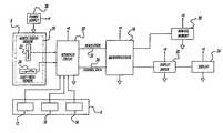
- FIG. 1is a block diagram of the electronic compass electrical circuit of the present invention.
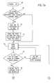
- FIGS. 2 a and 2 btogether represent a flow chart for the present invention which illustrates the calibration of the electronic compass.
- the compass system of the present inventionincludes a magnetic field sensor 10 packaged in a housing 8 and positions sensors 12 , 14 , and 16 of position sensor block 6 coupled to a microprocessor 18 through an electrical interface circuit 20 .
- sensor 10is comprised of individual sensors 22 and 24 which sense separate orthogonal components of the Earth's magnetic field
- microprocessor 18is an HC05 8-bit microprocessor manufactured by Motorola.
- Microprocessor 18 and circuit 20are coupled via serial communications lines 26 and 28 , and comprise a processing circuit for processing electrical signals supplied from sensors 12 , 14 , 16 , 22 , and 24 .
- nonvolatile memory circuit 30for storing compass data, a display driver 32 , and a display 34 for displaying heading information to the operator of the vehicle.
- Power supply circuit 36provides operating voltage to the various electrical components of the compass system. The functioning and interconnection of these circuits is now described in greater detail.
- Magnetic field sensors 22 and 24sense the horizontal components of the magnetic field external to the vehicle. Sensor 24 senses the east/west or channel 1 components of the field, and sensor 22 senses the north/south or channel 2 components of the field. As is described below, the magnetic field sensed by sensor 22 is said to have a positive polarity if it is in the north direction, and is said to have a negative polarity if it is in the south direction. Similarly, the magnetic field sensed by sensor 24 is said to have a positive polarity if it is in the East direction, and is said to have a negative polarity if it is in the west direction.
- a sensor 22is oriented to sense the component of the Earth's magnetic field existing along an axis corresponding to the vehicle's direction of travel and sensor 24 is oriented to sense the component existing in a direction perpendicular to the vehicle's direction of travel.
- sensors 22 and 24are magneto-inductive sensors, each having a wire-wound high magnetic permeability core constructed of Metals 2705M available from Allied Signal Corporation.
- the corehas dimensions of 0.020 inches ⁇ 0.600 inches ⁇ 0.001 inches, and is wound with approximately 2000 turns of 41 gauge wire.
- Sensors 22 and 24 of the preferred embodimentserve as inductive elements in an oscillator circuit formed with portions of interface circuit 20 , with the inductance of a particular sensor being dependent on the magnitude of the magnetic field in that sensor's direction of measurement. Through the generation of electrical signals having a frequency that varies with the external magnetic field, the vehicle direction can be ascertained.
- sensors 22 and 24are magneto-inductive sensors in the preferred embodiment, other types of sensors, such as magnetoresistive sensors, can be implemented if appropriate changes are made to the compass system. In an alternate embodiment described below, sensors 22 and 24 may also be replaced by a flux gate sensor. Such magnetic sensors and their calibration and operation are also discussed in U.S. Pat. Nos. 4,953,305 and 5,878,370, both of which are expressly incorporated herein by reference in their entirety.
- the position sensors 12 , 14 , 16 of sensor block 6provide information regarding the relative position of the compass system in a vehicle.
- sensors 12 and 14provide tilt information on whether the mirror has been moved back and forth and/or side to side, and sensor 16 provides rotational information concerning the rotation of the rearview mirror.
- sensors 12 and 14are potentiometers having a signal voltage which indicates whether the mirror has been tilted, although sensors 12 and 14 may comprise any sensor which indicates a change in mirror position such as a simple switch.
- Sensor 16provides a continuous signal that represents the extent of the mirror rotation and enables the electronic compass to calculate the rotational offset of the rearview mirror from a previously calibrated position.
- Sensor 16may be a rotational potentiometer, RVDT, optical encoder, or any other type of sensor which gives rotational position of the mirror.
- the position sensors 12 , 14 , and 16 of sensor block 6provide the compass system with the capability to recalibrate the compass system if the magnetic field sensor 10 is moved.
- sensor block 6is an optical sensor. More particularly sensor block 6 utilizes a photodetector and one or a plurality of light sources operated intermittently to generate positional information.
- FIGS. 2 a and 2 billustrate the calibration routine of the electronic compass using the positional sensor information output by sensor block 6 , such as sensors 12 , 14 , and 16 .
- the compass systemis powered up at block 38 , and the routine continues to block 40 while the stored channel data is compared to the current channel data provided by the sensors 22 and 24 . If the stored channel data is different than the current channel data, then the difference is added to Vref at block 42 to compensate for movement of the housing 8 in normal operation or while the system is powered down.
- the rotational or twist voltageis read from sensor 16 , and a corresponding rotational offset angle based upon the twist voltage is pulled from a reference table.
- the reference table stored in nonvolatile memory 30correlates the amount of rotation or movement to calibration values for the compass to maintain the correct directional readings. Control then proceeds to block 46 .
- the main loopwill begin at block 46 .
- the tilt or twist signals or voltage from sensor block 6such as from sensors 12 , 14 and 16 , will be analyzed at block 48 to determine if they are in the normal usage range. If the tilt or twist signals are not within the normal range, the routine will loop back to blocks 46 - 48 and a new heading will not be computed. This will address situations where the mirror housing has been moved for use by a passenger or otherwise displaced to where a driver could not use the mirror in its current position. If the tilt or twist signals are in the normal range (i.e., the normal position range of viewing for an adjustable rearview mirror), then the heading will be allowed to update at blocks 50 and 52 . At block 50 , the heading is updated, and at block 52 , the heading and average channel data is calculated.
- the routinewill check if the tilt sensors 12 and 14 voltages have exceeded a threshold voltage. If the tilt sensor 12 and 14 voltages have exceeded the threshold, then the routine at block 56 will wait until the new channel average is ready. When the new channel average is ready, the routine will continue to block 58 where the difference between the new and old channel averages will be taken and the reference voltages will be updated in accordance with the difference. If the new channel average is not ready, the routine will continue to loop at block 56 . Returning to block 54 if the tilt potentiometer voltage does not exceed a predetermined threshold, control proceeds to block 60 . Block 60 determines if the sensor 16 voltage has changed.
Landscapes
- Physics & Mathematics (AREA)
- Engineering & Computer Science (AREA)
- Radar, Positioning & Navigation (AREA)
- Remote Sensing (AREA)
- Life Sciences & Earth Sciences (AREA)
- Environmental & Geological Engineering (AREA)
- General Life Sciences & Earth Sciences (AREA)
- Geology (AREA)
- Electromagnetism (AREA)
- General Physics & Mathematics (AREA)
- Navigation (AREA)
Abstract
Description
This application claims the benefit of U.S. Provisional Patent Application No. 60/151,419, filed Aug. 30, 1999.
The present invention relates to an electronic compass. More specifically, the present invention relates to an electronic compass with a moveable sensor.
Electronic compasses are commonly used in vehicles as an aid for direction finding and navigation. An electronic compass may be positioned in a vehicle on the instrument panel, the rearview mirror, or at other locations within a vehicle. The positioning of the compass in the interior of a vehicle often determines how the compass is installed and packaged. For example, when an electronic compass is attached to an adjustable rearview mirror, the compass electronics package may be integrated with the mirror, while the magnetic sensors used by the electronic compass are normally fixed to a point on the vehicle that is stationary relative to the vehicle so as to avoid the loss of calibration when the mirror is moved. Accordingly, the magnetic sensor must often be wired remotely from the electronics mounted on the adjustable rearview mirror. This remote wiring is not aesthetically pleasing and increases the complexity of packaging for the electronic compass. It would be preferable to bundle all of the electronics for an electronic compass, including its magnetic sensors and electronics, in the same package. Thus, there is a need in the art for an electronic compass having a moveable magnetic sensor which can maintain its calibration.
In accordance with the present invention, an electronic compass is equipped with magnetic sensor position instrumentation which allows the magnetic sensors of the electronic compass to be moved relative to the vehicle while maintaining its calibration.
The instrumentation informs the compass electronics of any movement of the magnetic sensors relative to the vehicle so that this movement may be factored into the electronic compass directional calibration.
The magnetic sensor and position instrumentation are physically integrated into the electronics package for the electronic compass of the present invention, allowing the electronic compass to be unitarily packaged. This unitary packaging improves the aesthetic appearance of the electronic compass and allows it to be easily mounted on the interior of a vehicle. The unitary packaging also allows the electronic compass to be easily retrofitted in the automotive aftermarket.
The various advantages of the present invention will become apparent to those skilled in the art after reading the following specification and by reference to the drawings, in which:
FIG. 1 is a block diagram of the electronic compass electrical circuit of the present invention; and
FIGS. 2aand2btogether represent a flow chart for the present invention which illustrates the calibration of the electronic compass.
The following description of the present invention is merely exemplary in nature and is in no way intended to limit the invention or its uses. Moreover, the following description, while depicting an electronic compass designed to operate with a vehicle, is intended to adequately teach one skilled in the art to make and use the electronic compass of the present invention in any compass application.
Referring to FIG. 1, the compass system of the present invention includes amagnetic field sensor 10 packaged in ahousing 8 andpositions sensors position sensor block 6 coupled to amicroprocessor 18 through anelectrical interface circuit 20. In the preferred embodiment,sensor 10 is comprised ofindividual sensors microprocessor 18 is an HC05 8-bit microprocessor manufactured by Motorola.Microprocessor 18 andcircuit 20 are coupled viaserial communications lines sensors microprocessor 18 is anonvolatile memory circuit 30 for storing compass data, adisplay driver 32, and adisplay 34 for displaying heading information to the operator of the vehicle.Power supply circuit 36 provides operating voltage to the various electrical components of the compass system. The functioning and interconnection of these circuits is now described in greater detail.
In a preferred embodiment,sensors Sensors interface circuit 20, with the inductance of a particular sensor being dependent on the magnitude of the magnetic field in that sensor's direction of measurement. Through the generation of electrical signals having a frequency that varies with the external magnetic field, the vehicle direction can be ascertained. Althoughsensors sensors
Theposition sensors sensor block 6 provide information regarding the relative position of the compass system in a vehicle. For example, if the compass system is packaged in an adjustable rearview mirror,sensors sensor 16 provides rotational information concerning the rotation of the rearview mirror. In one embodiment of the present invention,sensors sensors Sensor 16 provides a continuous signal that represents the extent of the mirror rotation and enables the electronic compass to calculate the rotational offset of the rearview mirror from a previously calibrated position.Sensor 16 may be a rotational potentiometer, RVDT, optical encoder, or any other type of sensor which gives rotational position of the mirror. Theposition sensors sensor block 6 provide the compass system with the capability to recalibrate the compass system if themagnetic field sensor 10 is moved. In a preferred embodiment,sensor block 6 is an optical sensor. More particularlysensor block 6 utilizes a photodetector and one or a plurality of light sources operated intermittently to generate positional information.
The flow chart of FIGS. 2aand2billustrate the calibration routine of the electronic compass using the positional sensor information output bysensor block 6, such assensors block 38, and the routine continues to block40 while the stored channel data is compared to the current channel data provided by thesensors block 42 to compensate for movement of thehousing 8 in normal operation or while the system is powered down. Continuing toblock 44, the rotational or twist voltage is read fromsensor 16, and a corresponding rotational offset angle based upon the twist voltage is pulled from a reference table. The reference table stored innonvolatile memory 30 correlates the amount of rotation or movement to calibration values for the compass to maintain the correct directional readings. Control then proceeds to block46.
Returning toblock 40, if the stored channel data is not different from the current data, then the main loop will begin atblock 46. The tilt or twist signals or voltage fromsensor block 6, such as fromsensors block 48 to determine if they are in the normal usage range. If the tilt or twist signals are not within the normal range, the routine will loop back to blocks46-48 and a new heading will not be computed. This will address situations where the mirror housing has been moved for use by a passenger or otherwise displaced to where a driver could not use the mirror in its current position. If the tilt or twist signals are in the normal range (i.e., the normal position range of viewing for an adjustable rearview mirror), then the heading will be allowed to update atblocks block 50, the heading is updated, and atblock 52, the heading and average channel data is calculated.
Atblock 54, the routine will check if thetilt sensors tilt sensor block 56 will wait until the new channel average is ready. When the new channel average is ready, the routine will continue to block58 where the difference between the new and old channel averages will be taken and the reference voltages will be updated in accordance with the difference. If the new channel average is not ready, the routine will continue to loop atblock 56. Returning to block54 if the tilt potentiometer voltage does not exceed a predetermined threshold, control proceeds to block60.Block 60 determines if thesensor 16 voltage has changed. If thesensor 16 voltage has been changed, thesensor 16 voltage will be read and a heading offset will be retrieved from the reference table atblock 62. Control proceeds to block64 which checks if the ignition has been turned off and then returns to block46. If the ignition is off, the compass system will power down atblock 66.
It is to be understood that the invention is not limited to the exact construction illustrated and described above, but that various changes and modifications may be made without departing from the spirit and scope of the present invention.
Claims (37)
1. A compass system, comprising:
a housing, the housing supporting a compass unit;
a position sensor, the position sensor determining displacement of the housing with respect to a generally horizontal plane, the sensor generating a displacement signal;
a magnetic sensor, the magnetic sensor determining an orientation of the housing with respect to a magnetic field, the magnetic sensor generating a magnetic field signal;
a compensation controller, the compensation controller varying the magnetic field signal by an offset; and
an offset update circuit, the offset update circuit receiving the displacement signal and compensating for displacement of the housing by determining a first average magnetic field signal and comparing the first average magnetic field signal with a second average magnetic field signal generated prior to the first average magnetic field signal to define a difference signal, the difference signal being used to determine the offset.
2. The compass system ofclaim 1 wherein the position sensor is an optically triggered sensor.
3. The compass system ofclaim 1 further comprising a rotation sensor, the rotation sensor generating a rotation signal which varies in accordance with rotation of the housing about a generally vertical axis.
4. The compass system ofclaim 3 wherein the offset update circuit further includes a rotational update circuit receiving the rotation signal and determining a rotational offset, the rotational offset in part determining the offset.
5. The compass system ofclaim 3 wherein the position sensor and the rotation sensor are integral to form a composite sensor, and the composite sensor is optically triggered.
6. The compass system ofclaim 1 wherein the magnetic sensor determines the orientation of the housing with respect to the magnetic field of the earth.
7. The compass system ofclaim 1 wherein the magnetic sensor further comprises:
a first magnetic sensor for determining orientation of the compass unit with respect to a first magnetic axis; and
a second magnetic sensor for determining orientation of the compass unit with respect to a second magnetic axis orthogonal to the first magnetic axis.
8. The compass system ofclaim 7 wherein the magnetic field is the magnetic field of the earth.
9. The compass system ofclaim 7 wherein the first axis is one of a north/south and east/west axis, and the second axis is the other of the north/south and east/west axis.
10. A compass system, comprising:
a housing, the housing supporting a compass unit;
a position sensor, the position sensor determining displacement of the housing with respect to a generally horizontal plane, the sensor generating a displacement signal;
a first magnetic sensor for determining orientation of the compass unit with respect to a first magnetic axis, the first magnetic sensor generating a first magnetic field signal;
a second magnetic sensor for determining orientation of the compass unit with respect to a second magnetic axis orthogonal to the first magnetic axis, the second magnetic sensor generating a second magnetic field signal, wherein the first and second magnetic field signals are combined to define a composite magnetic field signal;
a compensation controller, the compensation controller varying the composite magnetic field signal by an offset; and
an offset update circuit, the offset update circuit receiving the displacement signal and compensating for displacement of the housing by determining a first average composite magnetic field signal and comparing the first average composite magnetic field signal with a second average composite magnetic field signal determined prior to the first average composite magnetic field signal to define a difference signal, the difference signal being used to determine the offset.
11. The compass system ofclaim 10 wherein the position sensor is an optically triggered sensor.
12. The compass system ofclaim 10 further comprising a rotation sensor, the rotation sensor generating a rotation signal which varies in accordance with rotation of the housing about a generally vertical axis.
13. The compass system ofclaim 12 wherein the offset update circuit further includes a rotational update circuit receiving the rotation signal and determining a rotational offset angle, the rotational offset angle in part determining the orientation of the housing.
14. The compass system ofclaim 13 wherein the position sensor and the rotation sensor are integral to form a composite sensor, and the composite sensor is optically triggered.
15. The compass system ofclaim 12 wherein the first and second magnetic sensors determine the orientation of the housing with respect to the magnetic field of the earth.
16. The compass system ofclaim 15 wherein the first axis is one of a north/south and east/west axis, and the second axis is the other of the north/south and east/west axis.
17. A method for compensating a compass mounted in a displaceable housing where displacement of the housing changes the orientation of the compass, comprising the step of:
determining if the housing has been tilted with respect to a horizontal plane;
determining a present magnetic orientation of the compass;
comparing the present magnetic orientation with a previous magnetic orientation to determine a difference between the present and previous magnetic orientations and generating an offset value; and
updating a calibration value in accordance with the offset values.
18. The method ofclaim 17 further comprising the steps of:
determining if the compass housing has been rotationally displaced with respect to a generally vertical axis;
determining a rotational signal in accordance with an amount of rotation of the housing; and
determining a rotational offset value compensating the magnetic heading in accordance with the rotational offset value.
19. A vehicle compass configured for mounting in an adjustable vehicle interior element comprising:
a magnetic field sensor configured to sense the Earth's magnetic field and to generate orientation signals representative of the orientation of the magnetic field sensor with respect to the Earth's magnetic field;
a position sensor configured to sense adjustments in the orientation of the magnetic field sensor as the vehicle interior element is adjusted and to generate position sensor signals; and
a control circuit configured to receive the orientation signals and the position sensor signals and to generate heading signals based on the orientation signals and the position sensor signals.
20. The vehicle compass ofclaim 19 wherein the position sensor is configured to sense tilting adjustments of the magnetic field sensor.
21. The vehicle compass ofclaim 19 wherein the position sensor is configured to sense twisting adjustments of the magnetic field sensor.
22. The vehicle compass ofclaim 19 further comprising means for determining whether the position sensor signals are within a normal usage range.
23. The vehicle compass ofclaim 19 further comprising a reference table for use in generating the heading signals.
24. The vehicle compass ofclaim 19 wherein the position sensor is selected from a rotational potentiometer, an RVDT, an optical encoder, and an optical sensor.
25. The vehicle compass ofclaim 19 wherein the position sensor comprises a photodetector and at least one light source.
26. The vehicle compass ofclaim 19 wherein the position sensor is selected from a magneto-inductive sensor and a magneto-restrictive sensor.
27. The vehicle compass ofclaim 19 further comprising a display, wherein the display receives the heading signals and provides a display of the heading signals.
28. The vehicle compass ofclaim 19 wherein the position sensor is configured to sense adjustments in the position of an adjustable rearview mirror.
29. A method for calibrating a compass system having a magnetic field sensor coupled to an adjustable vehicle interior element comprising:
providing a magnetic field signal;
providing a displacement signal based on a displacement of the magnetic field sensor; and
calculating a heading signal based on the magnetic field signal and the displacement signal.
30. The method ofclaim 29 wherein the displacement signal represents a tilting adjustment of the magnetic field sensor.
31. The method ofclaim 30 wherein the step of calculating a heading signal comprises receiving the displacement signal, determining a first magnetic orientation of the magnetic field sensor, and comparing the first magnetic orientation with a second magnetic field orientation of the magnetic field sensor determined prior to the first magnetic orientation.
32. The method ofclaim 29 wherein the displacement signal represents a twisting adjustment of the magnetic field sensor.
33. The method ofclaim 32 wherein the step of calculating a heading signal comprises receiving the displacement signal and retrieving a heading offset from a reference table.
34. The method ofclaim 29 further comprising determining whether the displacement signal is within a normal usage range.
35. The method ofclaim 29 wherein the magnetic field signal is based on an orientation of the magnetic field sensor with respect to a magnetic field.
36. The method ofclaim 35 wherein the magnetic field is a magnetic field of the Earth.
37. The method ofclaim 29 further comprising displaying the heading signal.
Priority Applications (1)
| Application Number | Priority Date | Filing Date | Title |
|---|---|---|---|
| US09/651,521US6418376B1 (en) | 1999-08-30 | 2000-08-30 | Method and apparatus to maintain compass heading with a moveable sensor mounting |
Applications Claiming Priority (2)
| Application Number | Priority Date | Filing Date | Title |
|---|---|---|---|
| US15141999P | 1999-08-30 | 1999-08-30 | |
| US09/651,521US6418376B1 (en) | 1999-08-30 | 2000-08-30 | Method and apparatus to maintain compass heading with a moveable sensor mounting |
Publications (1)
| Publication Number | Publication Date |
|---|---|
| US6418376B1true US6418376B1 (en) | 2002-07-09 |
Family
ID=26848616
Family Applications (1)
| Application Number | Title | Priority Date | Filing Date |
|---|---|---|---|
| US09/651,521Expired - LifetimeUS6418376B1 (en) | 1999-08-30 | 2000-08-30 | Method and apparatus to maintain compass heading with a moveable sensor mounting |
Country Status (1)
| Country | Link |
|---|---|
| US (1) | US6418376B1 (en) |
Cited By (41)
| Publication number | Priority date | Publication date | Assignee | Title |
|---|---|---|---|---|
| US20020196230A1 (en)* | 2001-06-22 | 2002-12-26 | Struyk David A. | Remote viewing system incorporating relative directional indication |
| US20040032675A1 (en)* | 2002-06-06 | 2004-02-19 | Weller Andrew D. | Interior rearview mirror system with compass |
| US20040128065A1 (en)* | 2000-03-09 | 2004-07-01 | Taylor David W. | Vehicle navigation system for use with a telematics system |
| US20040160313A1 (en)* | 1998-04-08 | 2004-08-19 | Donnelly Corporation | Wireless communication system |
| US20040236510A1 (en)* | 2002-03-01 | 2004-11-25 | Ockerse Harold C. | Electronic compass system |
| US20040254727A1 (en)* | 2002-03-01 | 2004-12-16 | Ockerse Harold C. | Electronic compass system |
| US20060132939A1 (en)* | 2002-06-06 | 2006-06-22 | Blank Rodney K | Interior rearview mirror system with compass |
| US20070101596A1 (en)* | 2003-04-30 | 2007-05-10 | Johnson Controls Technology Company | System and method for compensating for magnetic disturbance of a compass by a moveable vehicle accessory |
| US20070118280A1 (en)* | 1999-04-29 | 2007-05-24 | Donnelly Corporation | Navigation system for a vehicle |
| US20070162229A1 (en)* | 1999-11-24 | 2007-07-12 | Donnelly Corporation, A Corporation Of The State Of Michigan | Navigation system for a vehicle |
| US20080066331A1 (en)* | 2003-02-24 | 2008-03-20 | Johnson Controls Technology Company | Magnetometer correction system and method |
| US7494231B2 (en) | 1994-05-05 | 2009-02-24 | Donnelly Corporation | Vehicular signal mirror |
| US7579939B2 (en) | 1998-01-07 | 2009-08-25 | Donnelly Corporation | Video mirror system suitable for use in a vehicle |
| US7586666B2 (en) | 2002-09-20 | 2009-09-08 | Donnelly Corp. | Interior rearview mirror system for a vehicle |
| US7589883B2 (en) | 1994-05-05 | 2009-09-15 | Donnelly Corporation | Vehicular exterior mirror |
| US7619508B2 (en) | 2001-01-23 | 2009-11-17 | Donnelly Corporation | Video mirror system for a vehicle |
| US7667579B2 (en) | 1998-02-18 | 2010-02-23 | Donnelly Corporation | Interior mirror system |
| US7728721B2 (en) | 1998-01-07 | 2010-06-01 | Donnelly Corporation | Accessory system suitable for use in a vehicle |
| US7826123B2 (en) | 2002-09-20 | 2010-11-02 | Donnelly Corporation | Vehicular interior electrochromic rearview mirror assembly |
| US7855755B2 (en) | 2005-11-01 | 2010-12-21 | Donnelly Corporation | Interior rearview mirror assembly with display |
| US7864399B2 (en) | 2002-09-20 | 2011-01-04 | Donnelly Corporation | Reflective mirror assembly |
| US7888629B2 (en) | 1998-01-07 | 2011-02-15 | Donnelly Corporation | Vehicular accessory mounting system with a forwardly-viewing camera |
| US7898719B2 (en) | 2003-10-02 | 2011-03-01 | Donnelly Corporation | Rearview mirror assembly for vehicle |
| US7906756B2 (en) | 2002-05-03 | 2011-03-15 | Donnelly Corporation | Vehicle rearview mirror system |
| US7914188B2 (en) | 1997-08-25 | 2011-03-29 | Donnelly Corporation | Interior rearview mirror system for a vehicle |
| US7926960B2 (en) | 1999-11-24 | 2011-04-19 | Donnelly Corporation | Interior rearview mirror system for vehicle |
| US8019505B2 (en) | 2003-10-14 | 2011-09-13 | Donnelly Corporation | Vehicle information display |
| US8049640B2 (en) | 2003-05-19 | 2011-11-01 | Donnelly Corporation | Mirror assembly for vehicle |
| US8083386B2 (en) | 2001-01-23 | 2011-12-27 | Donnelly Corporation | Interior rearview mirror assembly with display device |
| US8154418B2 (en) | 2008-03-31 | 2012-04-10 | Magna Mirrors Of America, Inc. | Interior rearview mirror system |
| US8194133B2 (en) | 2000-03-02 | 2012-06-05 | Donnelly Corporation | Vehicular video mirror system |
| US8288711B2 (en) | 1998-01-07 | 2012-10-16 | Donnelly Corporation | Interior rearview mirror system with forwardly-viewing camera and a control |
| US8294975B2 (en) | 1997-08-25 | 2012-10-23 | Donnelly Corporation | Automotive rearview mirror assembly |
| US8462204B2 (en) | 1995-05-22 | 2013-06-11 | Donnelly Corporation | Vehicular vision system |
| US8503062B2 (en) | 2005-05-16 | 2013-08-06 | Donnelly Corporation | Rearview mirror element assembly for vehicle |
| US20140107860A1 (en)* | 2012-10-15 | 2014-04-17 | Gentex Corporation | Magnetic field compensation system and method thereof |
| US20160223350A1 (en)* | 2011-08-24 | 2016-08-04 | Modular Mining Systems, Inc. | Driver guidance for guided maneuvering |
| US9487144B2 (en) | 2008-10-16 | 2016-11-08 | Magna Mirrors Of America, Inc. | Interior mirror assembly with display |
| US9598016B2 (en) | 2010-10-15 | 2017-03-21 | Magna Mirrors Of America, Inc. | Interior rearview mirror assembly |
| WO2017180430A1 (en)* | 2016-04-08 | 2017-10-19 | Modular Mining Systems, Inc. | Driver guidance for guided maneuvering |
| US10330481B2 (en) | 2011-08-24 | 2019-06-25 | Modular Mining Systems, Inc. | Target destination selection for a mining vehicle |
Citations (9)
| Publication number | Priority date | Publication date | Assignee | Title |
|---|---|---|---|---|
| US4581827A (en)* | 1984-09-25 | 1986-04-15 | Niles Parts Co., Ltd. | Car door mirror equipped with bearing magnetometer |
| US4953305A (en)* | 1987-05-27 | 1990-09-04 | Prince Corporation | Vehicle compass with automatic continuous calibration |
| US5090231A (en)* | 1988-10-07 | 1992-02-25 | Gallagher Lawrence W | Electronic compass system |
| US5095631A (en)* | 1989-11-07 | 1992-03-17 | Solomon Gavril | Magnetic compass |
| US5737226A (en)* | 1995-06-05 | 1998-04-07 | Prince Corporation | Vehicle compass system with automatic calibration |
| US5761094A (en)* | 1996-01-18 | 1998-06-02 | Prince Corporation | Vehicle compass system |
| US5878370A (en) | 1995-12-01 | 1999-03-02 | Prince Corporation | Vehicle compass system with variable resolution |
| US6023229A (en) | 1999-03-02 | 2000-02-08 | Gentex Corp | Rearview mirror with internally-mounted compass sensor |
| US6243660B1 (en)* | 1999-10-12 | 2001-06-05 | Precision Navigation, Inc. | Digital compass with multiple sensing and reporting capability |
- 2000
- 2000-08-30USUS09/651,521patent/US6418376B1/ennot_activeExpired - Lifetime
Patent Citations (10)
| Publication number | Priority date | Publication date | Assignee | Title |
|---|---|---|---|---|
| US4581827A (en)* | 1984-09-25 | 1986-04-15 | Niles Parts Co., Ltd. | Car door mirror equipped with bearing magnetometer |
| US4953305A (en)* | 1987-05-27 | 1990-09-04 | Prince Corporation | Vehicle compass with automatic continuous calibration |
| US5090231A (en)* | 1988-10-07 | 1992-02-25 | Gallagher Lawrence W | Electronic compass system |
| US5095631A (en)* | 1989-11-07 | 1992-03-17 | Solomon Gavril | Magnetic compass |
| US5737226A (en)* | 1995-06-05 | 1998-04-07 | Prince Corporation | Vehicle compass system with automatic calibration |
| US5878370A (en) | 1995-12-01 | 1999-03-02 | Prince Corporation | Vehicle compass system with variable resolution |
| US5761094A (en)* | 1996-01-18 | 1998-06-02 | Prince Corporation | Vehicle compass system |
| US6023229A (en) | 1999-03-02 | 2000-02-08 | Gentex Corp | Rearview mirror with internally-mounted compass sensor |
| US6140933A (en)* | 1999-03-02 | 2000-10-31 | Gentex Corporation | Rearview mirror assembly with internally mounted compass sensor |
| US6243660B1 (en)* | 1999-10-12 | 2001-06-05 | Precision Navigation, Inc. | Digital compass with multiple sensing and reporting capability |
Cited By (208)
| Publication number | Priority date | Publication date | Assignee | Title |
|---|---|---|---|---|
| US7543947B2 (en) | 1994-05-05 | 2009-06-09 | Donnelly Corporation | Vehicular rearview mirror element having a display-on-demand display |
| US7871169B2 (en) | 1994-05-05 | 2011-01-18 | Donnelly Corporation | Vehicular signal mirror |
| US7771061B2 (en) | 1994-05-05 | 2010-08-10 | Donnelly Corporation | Display mirror assembly suitable for use in a vehicle |
| US7643200B2 (en) | 1994-05-05 | 2010-01-05 | Donnelly Corp. | Exterior reflective mirror element for a vehicle rearview mirror assembly |
| US7589883B2 (en) | 1994-05-05 | 2009-09-15 | Donnelly Corporation | Vehicular exterior mirror |
| US7572017B2 (en) | 1994-05-05 | 2009-08-11 | Donnelly Corporation | Signal mirror system for a vehicle |
| US8164817B2 (en) | 1994-05-05 | 2012-04-24 | Donnelly Corporation | Method of forming a mirrored bent cut glass shape for vehicular exterior rearview mirror assembly |
| US7494231B2 (en) | 1994-05-05 | 2009-02-24 | Donnelly Corporation | Vehicular signal mirror |
| US7821697B2 (en) | 1994-05-05 | 2010-10-26 | Donnelly Corporation | Exterior reflective mirror element for a vehicular rearview mirror assembly |
| US8511841B2 (en) | 1994-05-05 | 2013-08-20 | Donnelly Corporation | Vehicular blind spot indicator mirror |
| US8559093B2 (en) | 1995-04-27 | 2013-10-15 | Donnelly Corporation | Electrochromic mirror reflective element for vehicular rearview mirror assembly |
| US8462204B2 (en) | 1995-05-22 | 2013-06-11 | Donnelly Corporation | Vehicular vision system |
| US8842176B2 (en) | 1996-05-22 | 2014-09-23 | Donnelly Corporation | Automatic vehicle exterior light control |
| US8267559B2 (en) | 1997-08-25 | 2012-09-18 | Donnelly Corporation | Interior rearview mirror assembly for a vehicle |
| US8063753B2 (en) | 1997-08-25 | 2011-11-22 | Donnelly Corporation | Interior rearview mirror system |
| US8100568B2 (en) | 1997-08-25 | 2012-01-24 | Donnelly Corporation | Interior rearview mirror system for a vehicle |
| US8294975B2 (en) | 1997-08-25 | 2012-10-23 | Donnelly Corporation | Automotive rearview mirror assembly |
| US7898398B2 (en) | 1997-08-25 | 2011-03-01 | Donnelly Corporation | Interior mirror system |
| US8309907B2 (en) | 1997-08-25 | 2012-11-13 | Donnelly Corporation | Accessory system suitable for use in a vehicle and accommodating a rain sensor |
| US8610992B2 (en) | 1997-08-25 | 2013-12-17 | Donnelly Corporation | Variable transmission window |
| US8779910B2 (en) | 1997-08-25 | 2014-07-15 | Donnelly Corporation | Interior rearview mirror system |
| US7914188B2 (en) | 1997-08-25 | 2011-03-29 | Donnelly Corporation | Interior rearview mirror system for a vehicle |
| US8094002B2 (en) | 1998-01-07 | 2012-01-10 | Donnelly Corporation | Interior rearview mirror system |
| US8325028B2 (en) | 1998-01-07 | 2012-12-04 | Donnelly Corporation | Interior rearview mirror system |
| US7994471B2 (en) | 1998-01-07 | 2011-08-09 | Donnelly Corporation | Interior rearview mirror system with forwardly-viewing camera |
| US7916009B2 (en) | 1998-01-07 | 2011-03-29 | Donnelly Corporation | Accessory mounting system suitable for use in a vehicle |
| US8134117B2 (en) | 1998-01-07 | 2012-03-13 | Donnelly Corporation | Vehicular having a camera, a rain sensor and a single-ball interior electrochromic mirror assembly attached at an attachment element |
| US7579940B2 (en) | 1998-01-07 | 2009-08-25 | Donnelly Corporation | Information display system for a vehicle |
| US7728721B2 (en) | 1998-01-07 | 2010-06-01 | Donnelly Corporation | Accessory system suitable for use in a vehicle |
| US8288711B2 (en) | 1998-01-07 | 2012-10-16 | Donnelly Corporation | Interior rearview mirror system with forwardly-viewing camera and a control |
| US7579939B2 (en) | 1998-01-07 | 2009-08-25 | Donnelly Corporation | Video mirror system suitable for use in a vehicle |
| US7888629B2 (en) | 1998-01-07 | 2011-02-15 | Donnelly Corporation | Vehicular accessory mounting system with a forwardly-viewing camera |
| US7667579B2 (en) | 1998-02-18 | 2010-02-23 | Donnelly Corporation | Interior mirror system |
| US20080174414A1 (en)* | 1998-04-08 | 2008-07-24 | Donnelly Corporation | Vehicular communication system |
| US7382289B2 (en) | 1998-04-08 | 2008-06-03 | Donnelly Corporation | Vehicular communication system |
| US6909361B2 (en) | 1998-04-08 | 2005-06-21 | Donnelly Corporation | Wireless communication system |
| US20050156714A1 (en)* | 1998-04-08 | 2005-07-21 | Donnelly Corporation | Vehicular communication system |
| US9221399B2 (en) | 1998-04-08 | 2015-12-29 | Magna Mirrors Of America, Inc. | Automotive communication system |
| US9481306B2 (en) | 1998-04-08 | 2016-11-01 | Donnelly Corporation | Automotive communication system |
| US7916043B2 (en) | 1998-04-08 | 2011-03-29 | Donnelly Corporation | Vehicle communication system |
| US8525703B2 (en) | 1998-04-08 | 2013-09-03 | Donnelly Corporation | Interior rearview mirror system |
| US20040160313A1 (en)* | 1998-04-08 | 2004-08-19 | Donnelly Corporation | Wireless communication system |
| US8884788B2 (en) | 1998-04-08 | 2014-11-11 | Donnelly Corporation | Automotive communication system |
| US7583204B2 (en) | 1998-04-08 | 2009-09-01 | Donnelly Corporation | Wireless communication system in a vehicle |
| US20080300779A1 (en)* | 1999-04-29 | 2008-12-04 | Donnelly Corporation | Navigation system for a vehicle |
| US8768568B2 (en) | 1999-04-29 | 2014-07-01 | Magna Electronics Inc. | Driver assistance system for vehicle |
| US8355853B2 (en) | 1999-04-29 | 2013-01-15 | Donnelly Corporation | Control system for a hybrid vehicle |
| US20070118280A1 (en)* | 1999-04-29 | 2007-05-24 | Donnelly Corporation | Navigation system for a vehicle |
| US7412328B2 (en) | 1999-04-29 | 2008-08-12 | Donnelly Corporation | Navigation system for a vehicle |
| US7328103B2 (en) | 1999-11-24 | 2008-02-05 | Donnelly Corporation | Navigation system for a vehicle |
| US7580795B2 (en) | 1999-11-24 | 2009-08-25 | Donnelly Corporation | Vehicular navigation system |
| US9376061B2 (en) | 1999-11-24 | 2016-06-28 | Donnelly Corporation | Accessory system of a vehicle |
| US8162493B2 (en) | 1999-11-24 | 2012-04-24 | Donnelly Corporation | Interior rearview mirror assembly for vehicle |
| US9019091B2 (en) | 1999-11-24 | 2015-04-28 | Donnelly Corporation | Interior rearview mirror system |
| US7912646B2 (en) | 1999-11-24 | 2011-03-22 | Donnelly Corporation | Driver assistance system for vehicle |
| US20070162229A1 (en)* | 1999-11-24 | 2007-07-12 | Donnelly Corporation, A Corporation Of The State Of Michigan | Navigation system for a vehicle |
| US20090292466A1 (en)* | 1999-11-24 | 2009-11-26 | Donnelly Corporation | Navigation sytem for a vehicle |
| US7926960B2 (en) | 1999-11-24 | 2011-04-19 | Donnelly Corporation | Interior rearview mirror system for vehicle |
| US9278654B2 (en) | 1999-11-24 | 2016-03-08 | Donnelly Corporation | Interior rearview mirror system for vehicle |
| US10144355B2 (en) | 1999-11-24 | 2018-12-04 | Donnelly Corporation | Interior rearview mirror system for vehicle |
| US9315151B2 (en) | 2000-03-02 | 2016-04-19 | Magna Electronics Inc. | Driver assist system for vehicle |
| US8271187B2 (en) | 2000-03-02 | 2012-09-18 | Donnelly Corporation | Vehicular video mirror system |
| US7474963B2 (en) | 2000-03-02 | 2009-01-06 | Donnelly Corporation | Navigational mirror system for a vehicle |
| US10239457B2 (en) | 2000-03-02 | 2019-03-26 | Magna Electronics Inc. | Vehicular vision system |
| US10179545B2 (en) | 2000-03-02 | 2019-01-15 | Magna Electronics Inc. | Park-aid system for vehicle |
| US10131280B2 (en) | 2000-03-02 | 2018-11-20 | Donnelly Corporation | Vehicular video mirror system |
| US10053013B2 (en) | 2000-03-02 | 2018-08-21 | Magna Electronics Inc. | Vision system for vehicle |
| US9809171B2 (en) | 2000-03-02 | 2017-11-07 | Magna Electronics Inc. | Vision system for vehicle |
| US7490007B2 (en) | 2000-03-02 | 2009-02-10 | Donnelly Corporation | Video mirror system for a vehicle |
| US9809168B2 (en) | 2000-03-02 | 2017-11-07 | Magna Electronics Inc. | Driver assist system for vehicle |
| US9783114B2 (en) | 2000-03-02 | 2017-10-10 | Donnelly Corporation | Vehicular video mirror system |
| US8427288B2 (en) | 2000-03-02 | 2013-04-23 | Donnelly Corporation | Rear vision system for a vehicle |
| US7711479B2 (en) | 2000-03-02 | 2010-05-04 | Donnelly Corporation | Rearview assembly with display |
| US8543330B2 (en) | 2000-03-02 | 2013-09-24 | Donnelly Corporation | Driver assist system for vehicle |
| US7583184B2 (en) | 2000-03-02 | 2009-09-01 | Donnelly Corporation | Video mirror system suitable for use in a vehicle |
| US8095310B2 (en) | 2000-03-02 | 2012-01-10 | Donnelly Corporation | Video mirror system for a vehicle |
| US8194133B2 (en) | 2000-03-02 | 2012-06-05 | Donnelly Corporation | Vehicular video mirror system |
| US8179236B2 (en) | 2000-03-02 | 2012-05-15 | Donnelly Corporation | Video mirror system suitable for use in a vehicle |
| US7822543B2 (en) | 2000-03-02 | 2010-10-26 | Donnelly Corporation | Video display system for vehicle |
| US8000894B2 (en) | 2000-03-02 | 2011-08-16 | Donnelly Corporation | Vehicular wireless communication system |
| US8676491B2 (en) | 2000-03-02 | 2014-03-18 | Magna Electronics Inc. | Driver assist system for vehicle |
| US8044776B2 (en) | 2000-03-02 | 2011-10-25 | Donnelly Corporation | Rear vision system for vehicle |
| US9014966B2 (en) | 2000-03-02 | 2015-04-21 | Magna Electronics Inc. | Driver assist system for vehicle |
| US9019090B2 (en) | 2000-03-02 | 2015-04-28 | Magna Electronics Inc. | Vision system for vehicle |
| US8908039B2 (en) | 2000-03-02 | 2014-12-09 | Donnelly Corporation | Vehicular video mirror system |
| US8121787B2 (en) | 2000-03-02 | 2012-02-21 | Donnelly Corporation | Vehicular video mirror system |
| US7571042B2 (en) | 2000-03-02 | 2009-08-04 | Donnelly Corporation | Navigation system for a vehicle |
| US7167796B2 (en) | 2000-03-09 | 2007-01-23 | Donnelly Corporation | Vehicle navigation system for use with a telematics system |
| US20040128065A1 (en)* | 2000-03-09 | 2004-07-01 | Taylor David W. | Vehicle navigation system for use with a telematics system |
| US8072318B2 (en) | 2001-01-23 | 2011-12-06 | Donnelly Corporation | Video mirror system for vehicle |
| US10272839B2 (en) | 2001-01-23 | 2019-04-30 | Magna Electronics Inc. | Rear seat occupant monitoring system for vehicle |
| US7731403B2 (en) | 2001-01-23 | 2010-06-08 | Donnelly Corpoation | Lighting system for a vehicle, with high-intensity power LED |
| US9694749B2 (en) | 2001-01-23 | 2017-07-04 | Magna Electronics Inc. | Trailer hitching aid system for vehicle |
| US7619508B2 (en) | 2001-01-23 | 2009-11-17 | Donnelly Corporation | Video mirror system for a vehicle |
| US8083386B2 (en) | 2001-01-23 | 2011-12-27 | Donnelly Corporation | Interior rearview mirror assembly with display device |
| US9352623B2 (en) | 2001-01-23 | 2016-05-31 | Magna Electronics Inc. | Trailer hitching aid system for vehicle |
| US8653959B2 (en) | 2001-01-23 | 2014-02-18 | Donnelly Corporation | Video mirror system for a vehicle |
| US8654433B2 (en) | 2001-01-23 | 2014-02-18 | Magna Mirrors Of America, Inc. | Rearview mirror assembly for vehicle |
| US20020196230A1 (en)* | 2001-06-22 | 2002-12-26 | Struyk David A. | Remote viewing system incorporating relative directional indication |
| US6928366B2 (en) | 2002-03-01 | 2005-08-09 | Gentex Corporation | Electronic compass system |
| US20040254727A1 (en)* | 2002-03-01 | 2004-12-16 | Ockerse Harold C. | Electronic compass system |
| US20040236510A1 (en)* | 2002-03-01 | 2004-11-25 | Ockerse Harold C. | Electronic compass system |
| US20070124076A1 (en)* | 2002-03-01 | 2007-05-31 | Gentex Corporation | Electronic compass system |
| US7149627B2 (en) | 2002-03-01 | 2006-12-12 | Gentex Corporation | Electronic compass system |
| US6968273B2 (en) | 2002-03-01 | 2005-11-22 | Gentex Corporation | Electronic compass system |
| US7266452B2 (en) | 2002-03-01 | 2007-09-04 | Gentex Corporation | Electronic compass system |
| US7379814B2 (en) | 2002-03-01 | 2008-05-27 | Gentex Corporation | Electronic compass system |
| US7906756B2 (en) | 2002-05-03 | 2011-03-15 | Donnelly Corporation | Vehicle rearview mirror system |
| US8304711B2 (en) | 2002-05-03 | 2012-11-06 | Donnelly Corporation | Vehicle rearview mirror system |
| US8106347B2 (en) | 2002-05-03 | 2012-01-31 | Donnelly Corporation | Vehicle rearview mirror system |
| US8608327B2 (en) | 2002-06-06 | 2013-12-17 | Donnelly Corporation | Automatic compass system for vehicle |
| US7918570B2 (en) | 2002-06-06 | 2011-04-05 | Donnelly Corporation | Vehicular interior rearview information mirror system |
| US7832882B2 (en) | 2002-06-06 | 2010-11-16 | Donnelly Corporation | Information mirror system |
| US20040032675A1 (en)* | 2002-06-06 | 2004-02-19 | Weller Andrew D. | Interior rearview mirror system with compass |
| US7815326B2 (en) | 2002-06-06 | 2010-10-19 | Donnelly Corporation | Interior rearview mirror system |
| US7726822B2 (en) | 2002-06-06 | 2010-06-01 | Donnelly Corporation | Interior rearview mirror system |
| US7670016B2 (en) | 2002-06-06 | 2010-03-02 | Donnelly Corporation | Interior rearview mirror system with compass |
| US20100027145A1 (en)* | 2002-06-06 | 2010-02-04 | Donnelly Corporation | Interior rearview mirror system with compass |
| US7452090B2 (en) | 2002-06-06 | 2008-11-18 | Donnelly Corporation | Interior rearview mirror system with compass |
| US8282226B2 (en) | 2002-06-06 | 2012-10-09 | Donnelly Corporation | Interior rearview mirror system |
| US7600878B2 (en) | 2002-06-06 | 2009-10-13 | Donnelly Corp. | Interior rearview mirror system with compass |
| US8465162B2 (en) | 2002-06-06 | 2013-06-18 | Donnelly Corporation | Vehicular interior rearview mirror system |
| US8465163B2 (en) | 2002-06-06 | 2013-06-18 | Donnelly Corporation | Interior rearview mirror system |
| US20090231741A1 (en)* | 2002-06-06 | 2009-09-17 | Donnelly Corporation | Interior rearview mirror system with compass |
| US8047667B2 (en) | 2002-06-06 | 2011-11-01 | Donnelly Corporation | Vehicular interior rearview mirror system |
| US20090144996A1 (en)* | 2002-06-06 | 2009-06-11 | Donnelly Corporation | Interior rearview mirror system with compass |
| US7004593B2 (en) | 2002-06-06 | 2006-02-28 | Donnelly Corporation | Interior rearview mirror system with compass |
| US7329013B2 (en) | 2002-06-06 | 2008-02-12 | Donnelly Corporation | Interior rearview mirror system with compass |
| US20060132939A1 (en)* | 2002-06-06 | 2006-06-22 | Blank Rodney K | Interior rearview mirror system with compass |
| US7490944B2 (en) | 2002-06-06 | 2009-02-17 | Donnelly Corporation | Interior rearview mirror system with compass |
| US8777431B2 (en) | 2002-06-06 | 2014-07-15 | Donnelly Corporation | Integrated automatic compass for vehicle |
| US7540620B2 (en) | 2002-06-06 | 2009-06-02 | Donnelly Corporation | Video mirror system with compass |
| US20090059405A1 (en)* | 2002-06-06 | 2009-03-05 | Donnelly Corporation | Interior rearview mirror system with compass |
| US8177376B2 (en) | 2002-06-06 | 2012-05-15 | Donnelly Corporation | Vehicular interior rearview mirror system |
| US10029616B2 (en) | 2002-09-20 | 2018-07-24 | Donnelly Corporation | Rearview mirror assembly for vehicle |
| US8228588B2 (en) | 2002-09-20 | 2012-07-24 | Donnelly Corporation | Interior rearview mirror information display system for a vehicle |
| US10538202B2 (en) | 2002-09-20 | 2020-01-21 | Donnelly Corporation | Method of manufacturing variable reflectance mirror reflective element for exterior mirror assembly |
| US10363875B2 (en) | 2002-09-20 | 2019-07-30 | Donnelly Corportion | Vehicular exterior electrically variable reflectance mirror reflective element assembly |
| US7826123B2 (en) | 2002-09-20 | 2010-11-02 | Donnelly Corporation | Vehicular interior electrochromic rearview mirror assembly |
| US8727547B2 (en) | 2002-09-20 | 2014-05-20 | Donnelly Corporation | Variable reflectance mirror reflective element for exterior mirror assembly |
| US7859737B2 (en) | 2002-09-20 | 2010-12-28 | Donnelly Corporation | Interior rearview mirror system for a vehicle |
| US9878670B2 (en) | 2002-09-20 | 2018-01-30 | Donnelly Corporation | Variable reflectance mirror reflective element for exterior mirror assembly |
| US8277059B2 (en) | 2002-09-20 | 2012-10-02 | Donnelly Corporation | Vehicular electrochromic interior rearview mirror assembly |
| US8797627B2 (en) | 2002-09-20 | 2014-08-05 | Donnelly Corporation | Exterior rearview mirror assembly |
| US10661716B2 (en) | 2002-09-20 | 2020-05-26 | Donnelly Corporation | Vehicular exterior electrically variable reflectance mirror reflective element assembly |
| US9341914B2 (en) | 2002-09-20 | 2016-05-17 | Donnelly Corporation | Variable reflectance mirror reflective element for exterior mirror assembly |
| US7864399B2 (en) | 2002-09-20 | 2011-01-04 | Donnelly Corporation | Reflective mirror assembly |
| US8335032B2 (en) | 2002-09-20 | 2012-12-18 | Donnelly Corporation | Reflective mirror assembly |
| US8400704B2 (en) | 2002-09-20 | 2013-03-19 | Donnelly Corporation | Interior rearview mirror system for a vehicle |
| US7586666B2 (en) | 2002-09-20 | 2009-09-08 | Donnelly Corp. | Interior rearview mirror system for a vehicle |
| US8506096B2 (en) | 2002-09-20 | 2013-08-13 | Donnelly Corporation | Variable reflectance mirror reflective element for exterior mirror assembly |
| US9545883B2 (en) | 2002-09-20 | 2017-01-17 | Donnelly Corporation | Exterior rearview mirror assembly |
| US9073491B2 (en) | 2002-09-20 | 2015-07-07 | Donnelly Corporation | Exterior rearview mirror assembly |
| US9090211B2 (en) | 2002-09-20 | 2015-07-28 | Donnelly Corporation | Variable reflectance mirror reflective element for exterior mirror assembly |
| US20080066331A1 (en)* | 2003-02-24 | 2008-03-20 | Johnson Controls Technology Company | Magnetometer correction system and method |
| US7346995B2 (en) | 2003-04-30 | 2008-03-25 | Johnson Controls Technology Company | System and method for compensating for magnetic disturbance of a compass by a moveable vehicle accessory |
| US20070101596A1 (en)* | 2003-04-30 | 2007-05-10 | Johnson Controls Technology Company | System and method for compensating for magnetic disturbance of a compass by a moveable vehicle accessory |
| US9783115B2 (en) | 2003-05-19 | 2017-10-10 | Donnelly Corporation | Rearview mirror assembly for vehicle |
| US10449903B2 (en) | 2003-05-19 | 2019-10-22 | Donnelly Corporation | Rearview mirror assembly for vehicle |
| US11433816B2 (en) | 2003-05-19 | 2022-09-06 | Magna Mirrors Of America, Inc. | Vehicular interior rearview mirror assembly with cap portion |
| US8325055B2 (en) | 2003-05-19 | 2012-12-04 | Donnelly Corporation | Mirror assembly for vehicle |
| US10829052B2 (en) | 2003-05-19 | 2020-11-10 | Donnelly Corporation | Rearview mirror assembly for vehicle |
| US10166927B2 (en) | 2003-05-19 | 2019-01-01 | Donnelly Corporation | Rearview mirror assembly for vehicle |
| US8508384B2 (en) | 2003-05-19 | 2013-08-13 | Donnelly Corporation | Rearview mirror assembly for vehicle |
| US8049640B2 (en) | 2003-05-19 | 2011-11-01 | Donnelly Corporation | Mirror assembly for vehicle |
| US9557584B2 (en) | 2003-05-19 | 2017-01-31 | Donnelly Corporation | Rearview mirror assembly for vehicle |
| US8179586B2 (en) | 2003-10-02 | 2012-05-15 | Donnelly Corporation | Rearview mirror assembly for vehicle |
| US8705161B2 (en) | 2003-10-02 | 2014-04-22 | Donnelly Corporation | Method of manufacturing a reflective element for a vehicular rearview mirror assembly |
| US7898719B2 (en) | 2003-10-02 | 2011-03-01 | Donnelly Corporation | Rearview mirror assembly for vehicle |
| US8379289B2 (en) | 2003-10-02 | 2013-02-19 | Donnelly Corporation | Rearview mirror assembly for vehicle |
| US8355839B2 (en) | 2003-10-14 | 2013-01-15 | Donnelly Corporation | Vehicle vision system with night vision function |
| US8577549B2 (en) | 2003-10-14 | 2013-11-05 | Donnelly Corporation | Information display system for a vehicle |
| US8095260B1 (en) | 2003-10-14 | 2012-01-10 | Donnelly Corporation | Vehicle information display |
| US8170748B1 (en) | 2003-10-14 | 2012-05-01 | Donnelly Corporation | Vehicle information display system |
| US8019505B2 (en) | 2003-10-14 | 2011-09-13 | Donnelly Corporation | Vehicle information display |
| US8282253B2 (en) | 2004-11-22 | 2012-10-09 | Donnelly Corporation | Mirror reflective element sub-assembly for exterior rearview mirror of a vehicle |
| US8503062B2 (en) | 2005-05-16 | 2013-08-06 | Donnelly Corporation | Rearview mirror element assembly for vehicle |
| US9758102B1 (en) | 2005-09-14 | 2017-09-12 | Magna Mirrors Of America, Inc. | Mirror reflective element sub-assembly for exterior rearview mirror of a vehicle |
| US9694753B2 (en) | 2005-09-14 | 2017-07-04 | Magna Mirrors Of America, Inc. | Mirror reflective element sub-assembly for exterior rearview mirror of a vehicle |
| US8833987B2 (en) | 2005-09-14 | 2014-09-16 | Donnelly Corporation | Mirror reflective element sub-assembly for exterior rearview mirror of a vehicle |
| US10150417B2 (en) | 2005-09-14 | 2018-12-11 | Magna Mirrors Of America, Inc. | Mirror reflective element sub-assembly for exterior rearview mirror of a vehicle |
| US11072288B2 (en) | 2005-09-14 | 2021-07-27 | Magna Mirrors Of America, Inc. | Vehicular exterior rearview mirror assembly with blind spot indicator element |
| US11285879B2 (en) | 2005-09-14 | 2022-03-29 | Magna Mirrors Of America, Inc. | Vehicular exterior rearview mirror assembly with blind spot indicator element |
| US10829053B2 (en) | 2005-09-14 | 2020-11-10 | Magna Mirrors Of America, Inc. | Vehicular exterior rearview mirror assembly with blind spot indicator |
| US9045091B2 (en) | 2005-09-14 | 2015-06-02 | Donnelly Corporation | Mirror reflective element sub-assembly for exterior rearview mirror of a vehicle |
| US10308186B2 (en) | 2005-09-14 | 2019-06-04 | Magna Mirrors Of America, Inc. | Vehicular exterior rearview mirror assembly with blind spot indicator |
| US11124121B2 (en) | 2005-11-01 | 2021-09-21 | Magna Electronics Inc. | Vehicular vision system |
| US7855755B2 (en) | 2005-11-01 | 2010-12-21 | Donnelly Corporation | Interior rearview mirror assembly with display |
| US11970113B2 (en) | 2005-11-01 | 2024-04-30 | Magna Electronics Inc. | Vehicular vision system |
| US10175477B2 (en) | 2008-03-31 | 2019-01-08 | Magna Mirrors Of America, Inc. | Display system for vehicle |
| US8508383B2 (en) | 2008-03-31 | 2013-08-13 | Magna Mirrors of America, Inc | Interior rearview mirror system |
| US8154418B2 (en) | 2008-03-31 | 2012-04-10 | Magna Mirrors Of America, Inc. | Interior rearview mirror system |
| US11807164B2 (en) | 2008-10-16 | 2023-11-07 | Magna Mirrors Of America, Inc. | Vehicular video camera display system |
| US10583782B2 (en) | 2008-10-16 | 2020-03-10 | Magna Mirrors Of America, Inc. | Interior mirror assembly with display |
| US9487144B2 (en) | 2008-10-16 | 2016-11-08 | Magna Mirrors Of America, Inc. | Interior mirror assembly with display |
| US11577652B2 (en) | 2008-10-16 | 2023-02-14 | Magna Mirrors Of America, Inc. | Vehicular video camera display system |
| US12054098B2 (en) | 2008-10-16 | 2024-08-06 | Magna Mirrors Of America, Inc. | Vehicular video camera display system |
| US11021107B2 (en) | 2008-10-16 | 2021-06-01 | Magna Mirrors Of America, Inc. | Vehicular interior rearview mirror system with display |
| US12391183B2 (en) | 2008-10-16 | 2025-08-19 | Magna Mirrors Of America, Inc. | Vehicular video camera display system |
| US9598016B2 (en) | 2010-10-15 | 2017-03-21 | Magna Mirrors Of America, Inc. | Interior rearview mirror assembly |
| US11143517B2 (en) | 2011-08-24 | 2021-10-12 | Modular Mining Systems, Inc. | Driver guidance for guided maneuvering |
| US11193774B2 (en) | 2011-08-24 | 2021-12-07 | Modular Mining Systems, Inc. | Target destination selection for a mining vehicle |
| US20160223350A1 (en)* | 2011-08-24 | 2016-08-04 | Modular Mining Systems, Inc. | Driver guidance for guided maneuvering |
| US10330481B2 (en) | 2011-08-24 | 2019-06-25 | Modular Mining Systems, Inc. | Target destination selection for a mining vehicle |
| US9823082B2 (en)* | 2011-08-24 | 2017-11-21 | Modular Mining Systems, Inc. | Driver guidance for guided maneuvering |
| US9366537B2 (en)* | 2012-10-15 | 2016-06-14 | Gentex Corporation | Magnetic field compensation system and method thereof |
| US20140107860A1 (en)* | 2012-10-15 | 2014-04-17 | Gentex Corporation | Magnetic field compensation system and method thereof |
| WO2017180430A1 (en)* | 2016-04-08 | 2017-10-19 | Modular Mining Systems, Inc. | Driver guidance for guided maneuvering |
Similar Documents
| Publication | Publication Date | Title |
|---|---|---|
| US6418376B1 (en) | Method and apparatus to maintain compass heading with a moveable sensor mounting | |
| EP1580705B1 (en) | Rearview mirror assembly with internally mounted compass sensor | |
| US20030023380A1 (en) | Method of automatic continuous calibration for an electronic compass | |
| US7331115B2 (en) | Vehicle compass compensation | |
| CA2363472C (en) | Rearview mirror assembly with internally mounted compass sensor | |
| US9121706B2 (en) | Compass calibration system and method | |
| US20080066331A1 (en) | Magnetometer correction system and method | |
| KR100844521B1 (en) | Apparatus for providing an output signal correlated with the position of a part having a position range relative to the moving part and a method of determining the position of the moving part | |
| US6427349B1 (en) | Compensation system for electronic compass | |
| KR101221435B1 (en) | Electronic compass system | |
| EP0120691A2 (en) | Electrical compass | |
| KR101624185B1 (en) | Terminal, Vehicle communicating with the terminal and method for controlling the same | |
| US20070084070A1 (en) | Magnetic compass | |
| EP1618351B1 (en) | System and method for compensating for magnetic disturbance of a compass by a moveable vehicle accessory | |
| EP1422504A1 (en) | Liquid level sensor device | |
| US20030140510A1 (en) | Interruption of vehicle compass calibration in response to vehicle accessory interference | |
| WO2004076973A1 (en) | System and method for compensating for motor magnetic disturbance of a compass measurement | |
| US5828321A (en) | Location detecting system | |
| US5282318A (en) | Position sensor | |
| KR20060106407A (en) | Map Auto Scale Method of Navigation System | |
| JPS6196415A (en) | fuel gauge | |
| JPH02110317A (en) | Sensor output correction method | |
| MXPA01008714A (en) | Rearview mirror assembly with internally mounted compass sensor |
Legal Events
| Date | Code | Title | Description |
|---|---|---|---|
| AS | Assignment | Owner name:JOHNSON CONTROLS TECHNOLOGY COMPANY, MICHIGAN Free format text:ASSIGNMENT OF ASSIGNORS INTEREST;ASSIGNOR:OLSON, THOMAS R.;REEL/FRAME:011490/0908 Effective date:20010124 | |
| STCF | Information on status: patent grant | Free format text:PATENTED CASE | |
| FPAY | Fee payment | Year of fee payment:4 | |
| FEPP | Fee payment procedure | Free format text:PAYOR NUMBER ASSIGNED (ORIGINAL EVENT CODE: ASPN); ENTITY STATUS OF PATENT OWNER: LARGE ENTITY | |
| FPAY | Fee payment | Year of fee payment:8 | |
| FPAY | Fee payment | Year of fee payment:12 | |
| AS | Assignment | Owner name:VISTEON GLOBAL TECHNOLOGIES, INC., MICHIGAN Free format text:ASSIGNMENT OF ASSIGNORS INTEREST;ASSIGNOR:JOHNSON CONTROLS TECHNOLOGY COMPANY;REEL/FRAME:035091/0435 Effective date:20140701 |