US6418337B1 - MRI guided hyperthermia surgery - Google Patents
MRI guided hyperthermia surgeryDownload PDFInfo
- Publication number
- US6418337B1 US6418337B1US09/593,699US59369900AUS6418337B1US 6418337 B1US6418337 B1US 6418337B1US 59369900 AUS59369900 AUS 59369900AUS 6418337 B1US6418337 B1US 6418337B1
- Authority
- US
- United States
- Prior art keywords
- fiber
- axis
- probe
- disk
- drive assembly
- Prior art date
- Legal status (The legal status is an assumption and is not a legal conclusion. Google has not performed a legal analysis and makes no representation as to the accuracy of the status listed.)
- Expired - Lifetime, expires
Links
Images


Classifications
- A—HUMAN NECESSITIES
- A61—MEDICAL OR VETERINARY SCIENCE; HYGIENE
- A61B—DIAGNOSIS; SURGERY; IDENTIFICATION
- A61B18/00—Surgical instruments, devices or methods for transferring non-mechanical forms of energy to or from the body
- A61B18/18—Surgical instruments, devices or methods for transferring non-mechanical forms of energy to or from the body by applying electromagnetic radiation, e.g. microwaves
- A61B18/20—Surgical instruments, devices or methods for transferring non-mechanical forms of energy to or from the body by applying electromagnetic radiation, e.g. microwaves using laser
- A61B18/22—Surgical instruments, devices or methods for transferring non-mechanical forms of energy to or from the body by applying electromagnetic radiation, e.g. microwaves using laser the beam being directed along or through a flexible conduit, e.g. an optical fibre; Couplings or hand-pieces therefor
- A61B18/24—Surgical instruments, devices or methods for transferring non-mechanical forms of energy to or from the body by applying electromagnetic radiation, e.g. microwaves using laser the beam being directed along or through a flexible conduit, e.g. an optical fibre; Couplings or hand-pieces therefor with a catheter
- A—HUMAN NECESSITIES
- A61—MEDICAL OR VETERINARY SCIENCE; HYGIENE
- A61B—DIAGNOSIS; SURGERY; IDENTIFICATION
- A61B5/00—Measuring for diagnostic purposes; Identification of persons
- A61B5/05—Detecting, measuring or recording for diagnosis by means of electric currents or magnetic fields; Measuring using microwaves or radio waves
- A61B5/055—Detecting, measuring or recording for diagnosis by means of electric currents or magnetic fields; Measuring using microwaves or radio waves involving electronic [EMR] or nuclear [NMR] magnetic resonance, e.g. magnetic resonance imaging
- A—HUMAN NECESSITIES
- A61—MEDICAL OR VETERINARY SCIENCE; HYGIENE
- A61B—DIAGNOSIS; SURGERY; IDENTIFICATION
- A61B90/00—Instruments, implements or accessories specially adapted for surgery or diagnosis and not covered by any of the groups A61B1/00 - A61B50/00, e.g. for luxation treatment or for protecting wound edges
- A61B90/36—Image-producing devices or illumination devices not otherwise provided for
- A—HUMAN NECESSITIES
- A61—MEDICAL OR VETERINARY SCIENCE; HYGIENE
- A61B—DIAGNOSIS; SURGERY; IDENTIFICATION
- A61B18/00—Surgical instruments, devices or methods for transferring non-mechanical forms of energy to or from the body
- A61B18/18—Surgical instruments, devices or methods for transferring non-mechanical forms of energy to or from the body by applying electromagnetic radiation, e.g. microwaves
- A61B18/20—Surgical instruments, devices or methods for transferring non-mechanical forms of energy to or from the body by applying electromagnetic radiation, e.g. microwaves using laser
- A—HUMAN NECESSITIES
- A61—MEDICAL OR VETERINARY SCIENCE; HYGIENE
- A61B—DIAGNOSIS; SURGERY; IDENTIFICATION
- A61B18/00—Surgical instruments, devices or methods for transferring non-mechanical forms of energy to or from the body
- A61B2018/00005—Cooling or heating of the probe or tissue immediately surrounding the probe
- A61B2018/00011—Cooling or heating of the probe or tissue immediately surrounding the probe with fluids
- A61B2018/00023—Cooling or heating of the probe or tissue immediately surrounding the probe with fluids closed, i.e. without wound contact by the fluid
- A—HUMAN NECESSITIES
- A61—MEDICAL OR VETERINARY SCIENCE; HYGIENE
- A61B—DIAGNOSIS; SURGERY; IDENTIFICATION
- A61B18/00—Surgical instruments, devices or methods for transferring non-mechanical forms of energy to or from the body
- A61B2018/00053—Mechanical features of the instrument of device
- A61B2018/00184—Moving parts
- A61B2018/00196—Moving parts reciprocating lengthwise
- A—HUMAN NECESSITIES
- A61—MEDICAL OR VETERINARY SCIENCE; HYGIENE
- A61B—DIAGNOSIS; SURGERY; IDENTIFICATION
- A61B18/00—Surgical instruments, devices or methods for transferring non-mechanical forms of energy to or from the body
- A61B2018/00636—Sensing and controlling the application of energy
- A—HUMAN NECESSITIES
- A61—MEDICAL OR VETERINARY SCIENCE; HYGIENE
- A61B—DIAGNOSIS; SURGERY; IDENTIFICATION
- A61B18/00—Surgical instruments, devices or methods for transferring non-mechanical forms of energy to or from the body
- A61B18/18—Surgical instruments, devices or methods for transferring non-mechanical forms of energy to or from the body by applying electromagnetic radiation, e.g. microwaves
- A61B18/1815—Surgical instruments, devices or methods for transferring non-mechanical forms of energy to or from the body by applying electromagnetic radiation, e.g. microwaves using microwaves
- A61B2018/1861—Surgical instruments, devices or methods for transferring non-mechanical forms of energy to or from the body by applying electromagnetic radiation, e.g. microwaves using microwaves with an instrument inserted into a body lumen or cavity, e.g. a catheter
- A—HUMAN NECESSITIES
- A61—MEDICAL OR VETERINARY SCIENCE; HYGIENE
- A61B—DIAGNOSIS; SURGERY; IDENTIFICATION
- A61B18/00—Surgical instruments, devices or methods for transferring non-mechanical forms of energy to or from the body
- A61B18/18—Surgical instruments, devices or methods for transferring non-mechanical forms of energy to or from the body by applying electromagnetic radiation, e.g. microwaves
- A61B18/20—Surgical instruments, devices or methods for transferring non-mechanical forms of energy to or from the body by applying electromagnetic radiation, e.g. microwaves using laser
- A61B2018/2005—Surgical instruments, devices or methods for transferring non-mechanical forms of energy to or from the body by applying electromagnetic radiation, e.g. microwaves using laser with beam delivery through an interstitially insertable device, e.g. needle
- A—HUMAN NECESSITIES
- A61—MEDICAL OR VETERINARY SCIENCE; HYGIENE
- A61B—DIAGNOSIS; SURGERY; IDENTIFICATION
- A61B18/00—Surgical instruments, devices or methods for transferring non-mechanical forms of energy to or from the body
- A61B18/18—Surgical instruments, devices or methods for transferring non-mechanical forms of energy to or from the body by applying electromagnetic radiation, e.g. microwaves
- A61B18/20—Surgical instruments, devices or methods for transferring non-mechanical forms of energy to or from the body by applying electromagnetic radiation, e.g. microwaves using laser
- A61B18/22—Surgical instruments, devices or methods for transferring non-mechanical forms of energy to or from the body by applying electromagnetic radiation, e.g. microwaves using laser the beam being directed along or through a flexible conduit, e.g. an optical fibre; Couplings or hand-pieces therefor
- A61B2018/2255—Optical elements at the distal end of probe tips
- A61B2018/2272—Optical elements at the distal end of probe tips with reflective or refractive surfaces for deflecting the beam
- A61B2018/2277—Optical elements at the distal end of probe tips with reflective or refractive surfaces for deflecting the beam with refractive surfaces
- A—HUMAN NECESSITIES
- A61—MEDICAL OR VETERINARY SCIENCE; HYGIENE
- A61B—DIAGNOSIS; SURGERY; IDENTIFICATION
- A61B90/00—Instruments, implements or accessories specially adapted for surgery or diagnosis and not covered by any of the groups A61B1/00 - A61B50/00, e.g. for luxation treatment or for protecting wound edges
- A61B90/36—Image-producing devices or illumination devices not otherwise provided for
- A61B90/37—Surgical systems with images on a monitor during operation
- A61B2090/374—NMR or MRI
Definitions
- This inventionrelates to an apparatus for hyperthermia surgery in a patient using a magnetic resonance imaging system to effect guiding and control of the heating source.
- tumours and other masses to be excisedcan be heated above a predetermined temperature of the order of 55° C. so as to coagulate the portion of tissue heated.
- the temperature rangeis preferably of the order of 55 to 65° C. and does not reach temperatures which can cause ablation of the tissue.
- One technique for effecting the heatingis to insert into the mass concerned an optical fiber which has at its inserted end an element which redirects laser light from an exterior source in a direction generally at right angles to the length of the fiber.
- the energy from the laserthus extends into the tissue surrounding the end or tip and effects heating.
- the energyis directed in a beam confined to a relatively shallow angle so that, as the fiber is rotated, the beam also rotates around the axis of the fiber to effect heating of different parts of the mass at positions around the fiber.
- the fibercan thus be moved longitudinally and rotated to effect heating of the mass over the full volume of the mass with the intention of heating the mass to the required temperature without significantly affecting tissue surrounding the mass.
- the fiberis controlled and manipulated by a surgeon with little or no guidance apart from the knowledge of the surgeon of the anatomy of the patient and the location of the mass. It is difficult therefore for the surgeon to effect a controlled heating which heats all of the tumour while minimizing damage to surrounding tissue.
- the location of tumours and other masses to be excisedcan be determined by imaging using a magnetic resonance imaging system.
- the imaging systemthus generates for the surgeon a location of the mass to be excised but there is no system available which allows the surgeon to use the imaging system to control the heating effect.
- magnetic resonance imaging systemscan be used by modification of the imaging sequences to determine the temperature of tissue within the image and to determine changes in that temperature over time.
- U.S. Pat. No. 5,284,144also assigned to U.S. Department of Health and Human Services and issued Feb. 8, 1994 discloses an apparatus for hyperthermia treatment of cancer in which an external non-invasive heating system is mounted within the coil of a magnetic resonance imaging system.
- the disclosureis speculative and relates to initial experimentation concerning the viability of MRI measurement of temperature in conjunction with an external heating system.
- the disclosure of the patenthas not led to a commercially viable hyperthermic surgery system.
- U.S. Pat. Nos. 5,368,031 and 5,291,890 assigned to General Electricrelate to an MRI controlled heating system in which a point source of heat generates a predetermined heat distribution which is then monitored to ensure that the actual heat distribution follows the predicted heat distribution to obtain an overall heating of the area to be heated. Again this patented arrangement has not led to a commercially viable hyperthermia surgical system.
- controlling the heat sourceto effect heating of an area of the part adjacent the location
- the heat sourceis controlled by controlling an amount of heat generated thereby and by controlling a selected area of the part to which the heat is applied.
- the monitored locationsare arranged at an outer periphery of a volume to be heated to the required hyperthermic temperature.
- the methodincludes identifying the locations at the outer periphery of the volume, generally a tumor, to be heated from a preliminary series of signals from the non-invasive detection system.
- the heat sourceis provided on an invasive probe inserted into the part and wherein the control of the heat source is effected by moving the probe.
- control of the heat sourceis effected by moving the probe.
- non-invasive but directional heating techniquescan be used such as ultra-sound and other radiations.
- the heat sourceis provided on an invasive probe and is arranged to cause heating in a predetermined direction relative to the probe and wherein the control of the heat source is effected by moving the probe to alter the direction.
- the heat sourcecomprises a laser, an optical fiber for communicating light from the laser, a mounting for the optical fiber allowing invasive insertion of an end of the fiber into the part of the patient, a light directing element at an end of the fiber for directing the light from the laser to a predetermined direction relative to the fiber and a position control system for moving the end of the fiber.
- a cannulathrough which the fiber is inserted, the cannula having an end which is moved to a position immediately adjacent but outside the part to be heated and the fiber having a rigid end portion projecting from the end of the cannula into the part.
- a heat sourcearranged to apply heat to a part of a patient on whom the surgery is to be effected
- a non-invasive detection systemarranged to generate a series of output signals over a period of time representative of temperature in the part as the temperature of the part changes during that time;
- control systemcomprising:
- a first meansarranged to identify a plurality of locations in the part to be heated to a required hyperthermic temperature
- a second meansarranged to use the output signals to monitor the temperature at the locations as the temperature changes over the period of time;
- control systembeing arranged in response to said temperatures at the locations to operate the third means to control the selection of the area to which heat is applied and to control the amount of heat applied to the area.
- control systemincludes a first control for controlling an amount of heat generated by the heat source and a second control for moving the heat source to effect heating at a selected area of the part to which the heat is applied.
- the heat sourcecomprises: an optical fiber having an inlet end and an outlet end; a laser source for supplying light energy into the fiber at the inlet end; a light deflector at the outlet end for directing the light in a beam at an angle to a longitudinal axis of the fiber at the outlet end such that rotation of the fiber about the axis causes the beam to rotate about the axis; and a rigid elongate cannula arranged for insertion to a position at the part of the patient; the cannula having a bore arranged for receiving a portion of the fiber adjacent the outlet end in sliding engagement therein such that the end can pass through the cannula into engagement with the part of the patient.
- the third means of the control systemcomprises a drive assembly for causing a first longitudinal movement of the fiber relative to the cannula along its length and for causing a second rotational movement of the fiber about its axis.
- a mounting for the drive assemblyfor supporting the drive assembly exteriorly of the cannula and wherein the fiber has a reinforcing sleeve member surrounding and attached to a portion of the fiber so as to extend from the drive assembly to the outlet end, the sleeve member holding the fiber against lateral bending during said longitudinal movement and against torsional twisting during said rotational movement and the sleeve member being arranged to extend through the cannula.
- the sleeveincludes at least a portion which is integrally molded from a fiber reinforced polymer.
- the sleeveincludes a first portion at the outlet end which is formed of a first material, such as glass which is substantially rigid to rigidly support that portion of the fiber projecting in cantilever manner beyond the end of the cannula and a second portion connected to and extending from the first portion to the drive assembly, the second portion being formed of a second material such as liquid crystal polymer which is stiff but less rigid than the first portion to allow some flexing when the fiber is inserted into the cannula.
- the sleevecan be wholly formed from a material which allows the necessary stiffness but does not have the brittleness of for example glass.
- the reinforcing sleeveincludes an engagement portion attached thereto for engaging the drive assembly including a portion of polygonal cross-section for engaging into a drive collar of corresponding cross-section of the drive assembly for driving rotational movement of the fiber and including a shoulder section for engaging against a drive member of the drive assembly for driving longitudinal movement of the fiber.
- the non-invasive detection systemcomprises a magnetic resonance imaging system including a magnet to generate a magnetic field for the imaging system and an antenna for detecting radio frequency signals from the part of the patient; and wherein the third means of the control system includes a member located within and arranged to be moved within the magnetic field and a motor for driving movement of the member, the motor including no ferro-magnetic components such that it is usable in the magnetic field and the motor and a drive coupling thereto being shielded by a surrounding conductor to prevent interference with the radio frequency signals.
- the third means of the control systemincludes a driven member rotatable about an axis and a reciprocating drive element arranged to cause a ratcheting movement of the driven member.
- the reciprocating drive elementcomprises a piezo-electric motor.
- one driven memberincludes a sleeve arranged to receive the fiber therethrough and the fiber and sleeve are non circular or polygonal in shape such that rotation of the member causes rotation of the fiber about the axis while allowing longitudinal sliding movement of the fiber relative to the sleeve.
- one driven memberhas a female threaded bore therein and wherein the fiber has attached thereto a screw engaging the bore such that rotation of the driven member about the axis causes the screw to effect movement of the fiber longitudinally along the axis.
- an apparatuscomprising:
- a magnetic resonance imaging systemarranged to generate an image from a sample and including a magnet to generate a magnetic field and an antenna for detecting radio frequency signals from the sample;
- the motorhaving a drive coupling thereto for driving movement of the member, the motor including a reciprocating element for generating a motive force for the motor;
- the motorincluding no ferro-magnetic components such that it is usable in the magnetic field and the motor and the drive coupling being shielded by a surrounding conductor to prevent interference with the radio frequency signals.
- an apparatus for laser surgery on a part of a patientcomprising:
- optical fiberhaving an inlet end and an outlet end
- a laser sourcefor supplying light energy into the fiber at the inlet end
- a light deflectorat the outlet end for directing the light in a beam at an angle to a longitudinal axis of the fiber at the outlet end such that rotation of the fiber about the axis causes the beam to rotate about the axis;
- a rigid elongate cannulaarranged for insertion into the part of the patient
- the cannulahaving a bore arranged for receiving a portion of the fiber adjacent the outlet end in sliding engagement therein such that the end can pass through the cannula into engagement with the part of the patient;
- a drive assemblyfor causing a first longitudinal movement of the fiber relative to the cannula along its length and for causing a second rotational movement of the fiber about its axis;
- the fiberhaving a reinforcing sleeve member surrounding and attached to a portion of the fiber adjacent the outlet end, the sleeve member holding the fiber against lateral bending during said longitudinal movement and against torsional twisting during said rotational movement.
- a radiation sourcearranged to apply radiation to a part of a patient on whom the surgery is to be effected, the radiation being arranged to cause ablation of the part;
- the ablation of the partcan be effected by other forms of controlled directional radiation other than heat.
- the radiationis directed to the tip of the probe and controlled in direction and location while the effect of the radiation is monitored.
- Various forms of radiationcan be used provided they are directional and controllable and effect ablation of the part.
- the monitored locationsdefine an outer periphery of a volume such as a tumour to be ablated.
- the methodincludes identifying the outer periphery of the volume to be ablated from a preliminary series of signals from the non-invasive detection system and monitoring the effect of the radiation over the full area defined by the outer periphery.
- the radiation sourceis provided on an invasive probe inserted into the part and wherein the control of the radiation source is effected by moving the probe.
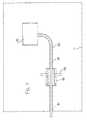
- FIG. 1is a schematic illustration of an apparatus for effecting MRI guided laser surgery according to the present invention.
- FIG. 2is a schematic illustration of the apparatus of FIG. 1 on an enlarged scale and showing the emission of laser energy into the brain of a patient.
- FIG. 3is a side elevational view of the laser probe of the apparatus of FIG. 1 .
- FIG. 4is an end elevational view of the laser probe of the apparatus of FIG. 1 .
- FIG. 5is a cross sectional view of the laser probe and drive motor therefor of the apparatus of FIG. 1 .
- FIG. 6is an exploded view of the drive motor of the apparatus of FIG. 1 .
- FIG. 7is a schematic illustration of the shielding of the apparatus of FIG. 1 .
- FIG. 8is a schematic illustration of the effect of the apparatus on a tumour or other mass to be ablated.
- FIG. 1is shown schematically an apparatus for carrying out MRI controlled laser surgery.
- the apparatuscomprises a magnetic resonance imaging system including a magnet 10 provided within a shielded room 11 .
- the magnet 10can be of any suitable construction and many different magnet arrangements are available from different manufacturers.
- the magnetincludes field coils for generating variations in the magnetic field which are not shown since these are well known to one skilled in the art together with a radio frequency antenna coil which receives signals from the sample in this case indicated as a human patient 13 .
- the patient 13rests upon a patient support table 14 on which the patient is supported and constrained against movement for the operative procedure.
- the fields of the magnetare controlled on an input control line 15 and the output from the antenna coil is provided on an output line 16 both of which communicate through a surgeon interface 17 to the conventional MRI control console 18 .
- the MRI console and the magnetare shown only schematically since these are well known to one skilled in the art and available from a number of different manufacturers.
- the apparatusfurther includes a laser surgery system including an optical fiber 20 which transmits heat energy in the form of light from a laser 21 mounted outside the room 11 .
- the fiberextends into the room to a tip 21 (FIG. 2) at which the energy escapes into the relevant part of the patient as discussed hereinafter.
- the position of the fiber 20 within the patient and the orientation of the fiberis controlled by a drive motor 22 supported in fixed adjustable position on a stereotaxic frame 23 .
- the motorcommunicates through a control line 24 to a device controller 25 .
- the device controllerreceives information from the MRI console and from position detectors of the motor 22 so as to operate movement of the motor 22 and to operate a power output from the laser 21 so as to control the position and amount of heat energy applied to the part within the body of the patient.
- FIG. 2is shown on a larger scale the patient table 14 to which is attached the stereotaxic frame 23 so that the frame is fixed relative to the table and extends over the head 26 of the patient.
- the frameis shown schematically and suitable details will be well known to one skilled in the art, but carries the motor 22 in a position on the frame by a bracket 27 of the motor.
- the position of the motor on the frameremains fixed during the procedure but can be adjusted in the arcuate direction 28 around the arch of the frame 23 .
- the frame 23can also be adjusted forwardly and rearwardly on the table 14 .
- the bracket 27also allows rotation of the motor about a point 30 within the frame so that the direction of the fiber projecting forwardly from the motor can be changed relative to the frame.
- the apparatusfurther includes a rigid cannula 31 which surrounds the fiber 20 and which is arranged to allow sliding movement of the fiber longitudinally in the cannula and rotational movement within the cannula while generally holding the fiber in a direction axial of the cannula.
- the cannulais formed of a suitable rigid ceramic material so that it is stiff and resistant to bending and has sufficient strength to allow the surgeon to insert the cannula into the required location within the body part of the patient.
- the apparatusis arranged for operating upon a tumour 32 within the brain 33 of the patient.
- the surgeontherefore creates an opening 34 in the skull of the patient and directs the cannula 31 , in the absence of the fiber 20 , through the opening 34 to the front edge of the tumour 32 .
- the position of the tumouris determined in an initial set of MRI experiments using conventional surgical and an analytical techniques to define the boundaries, that is a closed surface within the volume of the brain which constitutes the extremities of the tumour.
- the surgical analysis by which the surgeon determines exactly which portions of the material of the patient should be removedis not a part of this invention except to say that conventional surgical techniques are available to one skilled in the art to enable an analysis to be carried out to define the closed surface.
- the angle of insertion of the cannulais arranged so that, of course, it avoids as far as possible areas of the patient which should not be penetrated such as major blood vessels and also so that the cannula is directed so that, when it reaches the outside surface, it points toward a center of the tumour.
- the optical fiber structure generally indicated at 20 in FIG. 3includes an actual glass fiber element 35 which has an inlet end (not shown) at the laser and a remote end 36 .
- a reflector or prismwhich directs the laser energy in a beam 37 to one side of the end 36 .
- the beam 37is directed substantially at right angles to the length of the fiber and over a small angle around the axis of the fiber.
- the beam 37forms a cone having a cone angle of the order of 12 to 15 degrees.
- Such fibersare commercially available including the reflector or prism for directing the light at right angles to the length of the fiber.
- the fiber element itself as indicated at 35is however encased in an enclosure to allow the fiber to be manipulated in the motor 22 .
- a sleeve 38including a first end portion 39 and a second longer portion 40 .
- the end portion 39encloses the end 36 which is spaced from a tip 41 of the end portion.
- the end portionextends over the length of the order of 7 to 11 cms.
- the longer second portion 38is of the order of 48 to 77 cms in length and extends from a forward end 41 through to a rear end 42 .
- the front portion 39is formed of a rigid material such as glass.
- the longer rear portion 40is formed of a stiff material which is less brittle than glass and yet maintains bending and tortional stiffness of the fiber so that forces can be applied to the sleeve portion 40 to move the tip 36 of the fiber to a required position within the tumour.
- the second portion 40is formed of a material such as fiber reinforced plastics.
- the two portionsare bonded together to form an integral structure of common or constant diameter selected as a sliding fit through the cannula.
- the rigid front portionhas a length so that it can extend from the end of the cannula at the forward or closest edge of the tumour through to the rear edge of the tumour.
- An average tumourmight have a diameter of the order of 0.5 to 5.0 cms so that the above length of the forward portion is sufficient to extend through the full diameter of the tumour while leaving a portion of the order of 1.25 cms within the end of the cannula.
- the substantially rigid forward portionmaintains the forward portion of the fiber lying substantially directly along the axis of the cannula without any bending or twisting of the forward portion within the cannula.
- the longer second portionis not formed from glass since this would provide a complete structure which is too brittle to allow the surgeon to insert the structure into the cannula without the danger of cracking or fracturing the structure under any bending loads.
- a less brittle materialis therefore selected which can accommodate some bending loads caused by manual insertion of the structure into the cannula and yet can communicate the forces from longitudinal and rotational movement as described herein after.
- the sleeve portion 40has attached to it a first polygonal or non-circular section 44 and a second end stop section 45 . Both of the drive sections 44 and 45 are connected to the second portion so as to communicate driving action to the second portion.
- the polygonal section 44is arranged to co-operate with a drive member which acts to rotate the second portion and therefore the fiber along its full length about an axis longitudinal of the fiber.
- the second end stop section 45is arranged to co-operate with a longitudinally movable drive element which moves the second portion and therefore the fiber longitudinally. In this way the tip 36 can be moved from an initial position in which it projects just beyond the outer end of the cannula outwardly into the body of the tumour until the tip reaches the far end of the tumour.
- the tipcan be rotated around the axis of the fiber so that the heat energy can be applied at selected angles around the axis.
- the heat energycan be applied throughout a cylindrical volume extending from the end of the cannula along the axis of the cannula away from the end of the cannula.
- the heat energycan be caused to extend to required depths away from the axis of the cannula so as to effect heating of the body part of the patient over a selected volume with the intention of matching the volume of the tumour out to the predetermined closed surface area defining the boundary of the tumour.
- the non-circular cross section of the drive portion 44is rectangular with a height greater than the width.
- the cross sectionis constant along the length of the drive portion and provided that the drive portion can co-operate with a surrounding drive member to receive rotational driving force therefrom.
- the end stop member 45is generally cylindrical with a top segment 45 A removed to assist the operator in insertion of the fiber into the drive motor.
- FIGS. 5 and 6the drive motor 22 is shown in more detail for effecting a driving action on the fiber through the drive members 44 and 45 into the sleeve 38 for driving longitudinal and rotational movement of the tip 36 .
- the drive motorcomprises a housing 50 formed by an upper half 51 and a lower half 52 both of semi-cylindrical shape with the two portions engaged together to surround the drive elements with the fiber extending axially along a center of the housing.
- a bossdefining a bore 54 within which the sleeve 38 forms a sliding fit. This acts to guide the movement of the sleeve at the forward end of the housing.
- first annular mount 55Within the housing is provided a first annular mount 55 and a second annular mount 56 spaced rearwardly from the first. Between the first annular mount and the front boss is provided a first encoder 57 and behind the second annular mount 56 is provided a second encoder 58 .
- the first annular mount 55mounts a first rotatable drive disk 59 on bearings 60 .
- the second annular mountcarries a second drive disk 61 on bearings 62 .
- Each of the drive disksis of the same shape including a generally flat disk portion with a cylindrical portion 63 on the rear of the disk and lying on a common axis with the disk portion.
- the bearingsare mounted between a cylindrical inner face of the annular portion 55 , 56 and an outside surface of the cylindrical portions 63 . Each of the disks is therefore mounted for rotation about the axis of the fiber along the axis of the housing.
- the disk 59includes a central plug portion 64 which closes the center hole of the disk portion and projects into the cylindrical portion 63 .
- the plug portionhas a chamfered or frusto-conical lead in section 65 converging to a drive surface 66 surrounding the drive member 44 and having a common cross sectional shape therewith.
- the tip portion 41 of the sleeve 38can slide along the axis of the housing and engage into the conical lead in section 65 so as to pass through the drive surface or bore 66 until the drive member 44 engages into the surface 66 .
- rotation of the disk 59drives rotation of the sleeve 38 and therefore of the fiber.
- the drive portion 44has a constant cross section, it can slide through the drive surface 66 forwardly and rearwardly.
- the disk 61includes a plug member 67 which engages into the central opening in the disk member 61 .
- the plug 67has an inner surface 68 which defines a female screw thread for co-operating with a lead screw 69 .
- the lead screw 69has an inner bore 70 surrounding the sleeve 38 so that the sleeve 38 is free to rotate and move relative to the bore 70 .
- the lead screw 69also passes through the cylindrical portion 63 of the disk 61 . However rotation of the disk 61 acts to drive the lead screw longitudinally of the axis of the housing and therefore of the axis of the sleeve 38 .
- a rear end 71 of the lead screwis attached to a clamping member 72 .
- the clamping member 72includes a first fixed portion 73 attached to the rear end 71 of the lead screw and a second loose portion 74 which can be clamped into engaging the fixed portion so as to clamp the end stop members 45 in position within the clamping member.
- the loose portion 74is clamped in place by screws 75 .
- the top segment 45 A of the end stop 45engages into a receptacle 76 in the fixed portion 73 so as to orient the sleeve 38 relative to the lead screw.
- the disks 59 and 61are driven in a ratchetting action by drive motors 77 and 78 respectively.
- the drive motorsare provided by piezo-electric drive elements in which a piezo-electric crystal is caused to oscillate thus actuating a reciprocating action which is used to drive by a ratchet process angular rotation of the respective disk.
- the reciprocating action of the piezo-electric crystal 77 and 78is provided by two such motors 77 co-operating with the disk 59 and two motors 78 co-operating with the disk 61 .
- Each motoris carried on a mounting bracket 77 A, 78 A which is suitably attached to the housing.
- the end clamp 72is generally rectangular in cross section and slides within a correspondingly rectangular cross section duct 72 A within the housing.
- the lead screw 69is held against rotation and is driven axially by the rotation of the disk 61 while the fiber is free to rotate relative to the lead screw.
- the ratchetting actioncan be effected by a longitudinally moveable cable driven from the device controller 25 outside the room 11 .
- the motormay comprise a hydraulic or pneumatic motor which again effects a ratchetting action by reciprocating movement of a pneumatically or hydraulically driven prime mover.
- the respective encoder 57 , 58detects the instantaneous position of the disk and particularly the sleeve portion 63 of the disk which projects into the interior of the encoder.
- the sleeve portiontherefore carries a suitable elements which allows the encoder to detect accurately the angular orientation of the respective disk.
- the position of the diskscan be controlled by the device controller 25 accurately moving the disk 59 to control the angular orientation of the fiber and accurately moving the disk 61 to control the longitudinal position of the fiber.
- the longitudinal positionis of course obtained by moving the lead screw longitudinally which carries the end stop 45 longitudinally. The movements are independent so that the fiber can be rotated while held longitudinally stationary.
- the motor driving movement of the fiberis used while the magnet and the MRI system is in operation, it is essential that the motor and the associated control elements that are located within the room 11 are compatible with the MRI system.
- the power supply or control cable 24 and the motormust both be free from ferromagnetic components which would be responsive to the magnetic field.
- the motor 22 and the cable 24are both properly shielded against interference with the small radio frequency signals which must be detected for the MRI analysis to be effective.
- the room 11is surrounded by a conductor which prevents penetration of radio frequency interference into the area within the room at the magnet.
- the cable 24 and the motor 22are surrounded by a conductor 80 which extends through an opening 81 in the conductor at the wall 11 through a cable port 82 within the wall 83 of the enclosure so that the whole of the motor and the cable are encased within the conductor 80 which is connected to the conductor within the wall.
- the conductor 80acts as a “worm hole” in the shielding thus retaining the motor 22 and the cable 24 effectively external to the shielding at the periphery of the room.
- the use of a Piezo-electric crystal to drive disksis particularly suitable and provides particular compatibility with the MRI system but other drive systems can also be used as set forth previously.
- the patientis located on the patient table and so to be restrained so that the head of the patient is held fixed within the magnet to prevent motion artefacts.
- the MRI systemis then operated in conventional manner to generate an image of the portion, generally a tumour, to be excised.
- the surgeonalone or in conjunction with suitable software available to one skilled in the art then analyses the images developed to locate the closed area surrounding the volume of the tumour and defining the external perimeter of the tumour as indicated at FIG. 8 at 90 .
- the surgeonalso determines the best route for directing the cannula to the tumour to avoid damaging intervening tissue and to provide a best course to the centre of the tumour which may be irregular in shape.
- the opening 34is formed and the cannula inserted as previously described.
- the motorWith the cannula in place, the motor is mounted on the frame and the frame adjusted to locate the motor so that the fiber can be inserted directly along the length of the cannula. With the motor properly aligned along the axis of the cannula, the fiber is inserted through the bore of the motor and into the cannula so as to extend through the cannula until the tip emerges just out of the outer end of the cannula. The distance of the motor from the cannula can be adjusted so that the tip just reaches the end of the cannula when the lead screw is fully retracted and the end stop is located in place in the clamp 72 .
- the MRI systemis arranged to carry out experiments which generate temperature measurements in the boundary zone 90 .
- the temperatureis detected over the full surface area of the boundary rather than simply at a number of discrete locations. While the experiments to detect the temperature are continued, the fiber is moved longitudinally to commence operation at a first position just inside the volume of the tumour. At a selected angular orientation of the beam, pulses of radiation are emitted by the laser and transmitted into the tumour through the beam 37 . The pulses are continued while the temperature in the boundary layer 90 is detected.
- the tumourAs the pulses supply heat energy into the volume of the tumour, the tumour is heated locally basically in the volume defined by the beam but also heat is conducted out of the volume of the beam into the remainder of the tumour at a rate dependent upon the characteristics of the tumour itself. Heating at a localised area defined by the beam is therefore continued until the heat at the boundary layer 90 is raised to the predetermined coagulation temperature of the order of 55 to 65° C. Once the boundary layer reaches this temperature, heating at that zone is discontinued and the fiber is moved either longitudinally or angularly or both to move to the next zone of the tumour to be heated. It is not necessary to predict the required number of pulses in advance since the detection of temperature at the boundary is done in real time and sufficiently quickly to prevent overshoot. However, predictions can be made in some circumstances in order to carry out the application of the heat energy as quickly as possible.
- the number of pulses per secondmay also be varied based upon the above predication depending upon the characteristics of the tumour as detected in the initial analysis.
- the energy application ratecannot be so high that the temperature rises too quickly so that over shooting of the desired temperature at the boundary occurs with the possibility of damage to tissue outside the boundary.
- the rate of energy applicationis therefore selected depending upon the size and consistency of the tumour to effect heating at a controlled rate in order to achieve the required temperature at the boundary without the possibility of over shoot.
- the rate of heat applicationcan also be varied in dependence upon the distance of the boundary from the axis of the fiber.
- the axis of the fiberis indicated at 91 in FIG. 8 and a first distance 92 of the beam to the boundary is relatively short at the entry point of the fiber into the tumour and increases to a second larger distance 93 toward the center of the tumour.
- the fiberis then rotated through an angle approximately equal to the beam angle to commence heating at a second angular orientation with the fiber being rotated to a next angular orientation only when heating at that second orientation is complete. In this way heating is effected at each position and then the fiber rotated to a next orientation position until all angular orientations are completed.
- the fiberAfter a first disk shaped portion of the tumour is thus heated, the fiber is moved longitudinally through a distance dependant upon the diameter of the tumour at that location and dependant upon the beam angle so as to ensure the next disk shaped volume of tumour heated contains all of the tumour structure without intervening localised portions of the tumour which are not heated to the required temperature.
- the fiberis moved longitudinally in steps which may vary in distance depending upon the diameter and structure of the tumour as determined by the initial analysis.
- the total heating of the tumouris preferably determined by the temperature at the boundary without the necessity for analysis of the temperatures of the tumour inside the boundary or any calculations of temperature gradients within the tumour.
- the surgeryis complete and the apparatus is disassembled for removal of the fiber and the cannula from the patient.
- the systemallows direct and accurate control of the heating by controlling the temperature at the surface area defined by the boundary of the tumour so that the whole of the volume of the tumour is properly heated to the required temperature without the danger of heating areas external to the tumour beyond the coagulation temperature.
Landscapes
- Health & Medical Sciences (AREA)
- Life Sciences & Earth Sciences (AREA)
- Surgery (AREA)
- Physics & Mathematics (AREA)
- Nuclear Medicine, Radiotherapy & Molecular Imaging (AREA)
- Molecular Biology (AREA)
- Veterinary Medicine (AREA)
- Public Health (AREA)
- Engineering & Computer Science (AREA)
- Biomedical Technology (AREA)
- Heart & Thoracic Surgery (AREA)
- Medical Informatics (AREA)
- General Health & Medical Sciences (AREA)
- Animal Behavior & Ethology (AREA)
- Pathology (AREA)
- Optics & Photonics (AREA)
- Electromagnetism (AREA)
- Otolaryngology (AREA)
- Oral & Maxillofacial Surgery (AREA)
- Radiology & Medical Imaging (AREA)
- High Energy & Nuclear Physics (AREA)
- Biophysics (AREA)
- Laser Surgery Devices (AREA)
- Radiation-Therapy Devices (AREA)
- Magnetic Resonance Imaging Apparatus (AREA)
- Thermotherapy And Cooling Therapy Devices (AREA)
- Medicines Containing Antibodies Or Antigens For Use As Internal Diagnostic Agents (AREA)
Abstract
Description
Claims (36)
Priority Applications (18)
| Application Number | Priority Date | Filing Date | Title |
|---|---|---|---|
| US09/593,699US6418337B1 (en) | 2000-06-15 | 2000-06-15 | MRI guided hyperthermia surgery |
| ES01944836TES2322026T3 (en) | 2000-06-15 | 2001-06-15 | HYPERTHERMIA SURGERY GUIDED BY MRI. |
| AU2001267231AAU2001267231A1 (en) | 2000-06-15 | 2001-06-15 | Mri guided hyperthermia surgery |
| DE60137687TDE60137687D1 (en) | 2000-06-15 | 2001-06-15 | MRI MONITORED HYPERTHERMIC SURGERY |
| PCT/CA2001/000905WO2001095821A2 (en) | 2000-06-15 | 2001-06-15 | Mri guided hyperthermia surgery |
| JP2002510007AJP4417006B2 (en) | 2000-06-15 | 2001-06-15 | MRI induction thermosurgical instrument |
| CA2408811ACA2408811C (en) | 2000-06-15 | 2001-06-15 | Mri guided hyperthermia surgery |
| CA2757358ACA2757358A1 (en) | 2000-06-15 | 2001-06-15 | Apparatus for mri guided hyperthermia surgery |
| EP01944836AEP1289441B1 (en) | 2000-06-15 | 2001-06-15 | Mri guided hyperthermia surgery |
| CA2690040ACA2690040C (en) | 2000-06-15 | 2001-06-15 | Apparatus for mri guided hyperthermia surgery |
| EP09152951.1AEP2055232B1 (en) | 2000-06-15 | 2001-06-15 | MRI Guided Hyperthermia Surgery |
| AT01944836TATE422850T1 (en) | 2000-06-15 | 2001-06-15 | MRI MONITORED HYPERTHERMAL SURGERY |
| US10/014,846US7167741B2 (en) | 2000-06-15 | 2001-12-14 | Hyperthermia treatment and probe therefor |
| HK09105043.7AHK1126379B (en) | 2000-06-15 | 2009-06-04 | Mri guided hyperthermia surgery |
| JP2009224862AJP5155273B2 (en) | 2000-06-15 | 2009-09-29 | MRI induction thermosurgical instrument |
| US13/601,134US20130006230A1 (en) | 2000-06-15 | 2012-08-31 | Hyperthermia treatment and probe therefor |
| US13/932,725US9387042B2 (en) | 2000-06-15 | 2013-07-01 | Hyperthermia treatment and probe therefor |
| US14/218,764US9333038B2 (en) | 2000-06-15 | 2014-03-18 | Hyperthermia treatment and probe therefore |
Applications Claiming Priority (1)
| Application Number | Priority Date | Filing Date | Title |
|---|---|---|---|
| US09/593,699US6418337B1 (en) | 2000-06-15 | 2000-06-15 | MRI guided hyperthermia surgery |
Related Child Applications (2)
| Application Number | Title | Priority Date | Filing Date |
|---|---|---|---|
| PCT/CA2001/000905Continuation-In-PartWO2001095821A2 (en) | 2000-06-15 | 2001-06-15 | Mri guided hyperthermia surgery |
| PCT/CA2001/000905ContinuationWO2001095821A2 (en) | 2000-06-15 | 2001-06-15 | Mri guided hyperthermia surgery |
Publications (1)
| Publication Number | Publication Date |
|---|---|
| US6418337B1true US6418337B1 (en) | 2002-07-09 |
Family
ID=24375772
Family Applications (2)
| Application Number | Title | Priority Date | Filing Date |
|---|---|---|---|
| US09/593,699Expired - LifetimeUS6418337B1 (en) | 2000-06-15 | 2000-06-15 | MRI guided hyperthermia surgery |
| US10/014,846Expired - LifetimeUS7167741B2 (en) | 2000-06-15 | 2001-12-14 | Hyperthermia treatment and probe therefor |
Family Applications After (1)
| Application Number | Title | Priority Date | Filing Date |
|---|---|---|---|
| US10/014,846Expired - LifetimeUS7167741B2 (en) | 2000-06-15 | 2001-12-14 | Hyperthermia treatment and probe therefor |
Country Status (9)
| Country | Link |
|---|---|
| US (2) | US6418337B1 (en) |
| EP (2) | EP1289441B1 (en) |
| JP (2) | JP4417006B2 (en) |
| AT (1) | ATE422850T1 (en) |
| AU (1) | AU2001267231A1 (en) |
| CA (3) | CA2690040C (en) |
| DE (1) | DE60137687D1 (en) |
| ES (1) | ES2322026T3 (en) |
| WO (1) | WO2001095821A2 (en) |
Cited By (39)
| Publication number | Priority date | Publication date | Assignee | Title |
|---|---|---|---|---|
| US20030183972A1 (en)* | 2002-03-28 | 2003-10-02 | Jan Weber | Method and apparatus for extruding polymers employing microwave energy |
| US20030183966A1 (en)* | 2002-03-28 | 2003-10-02 | Lixiao Wang | Method of manufacture medical devices employing microwave energy |
| US20040021249A1 (en)* | 2002-03-28 | 2004-02-05 | Jan Weber | Polymer welding using ferromagnetic particles |
| WO2003105925A3 (en)* | 2002-06-17 | 2004-05-06 | Roger E Susi | Non-magnetic medical infusion device |
| US20040193039A1 (en)* | 2003-03-27 | 2004-09-30 | Jan Weber | Medical device with temperature modulator for use in magnetic resonance imaging |
| US20040249261A1 (en)* | 2001-06-15 | 2004-12-09 | Torchia Mark G. | Hyperthermia treatment and probe therefor |
| US20060079758A1 (en)* | 2004-10-12 | 2006-04-13 | Susi Roger E | Non-magnetic medical infusion device |
| US20060173412A1 (en)* | 2002-06-17 | 2006-08-03 | Susi Roger E | Liquid infusion apparatus |
| US20060206105A1 (en)* | 2005-03-09 | 2006-09-14 | Rajiv Chopra | Treatment of diseased tissue using controlled ultrasonic heating |
| US20070167742A1 (en)* | 2005-12-30 | 2007-07-19 | David Wurmfeld | Position detection in a magnetic field |
| US20070222450A1 (en)* | 2006-03-21 | 2007-09-27 | Fonar Corporation | System for magnetic resonance imaging assisted surgery |
| US20070239062A1 (en)* | 2005-03-09 | 2007-10-11 | Rajiv Chopra | Method and apparatus for obtaining quantitative temperature measurements in prostate and other tissue undergoing thermal therapy treatment |
| US20080154252A1 (en)* | 2001-06-15 | 2008-06-26 | Monteris Medical, Inc. | Hyperthermia Treatment and Probe Therefor |
| US20080177268A1 (en)* | 2002-02-14 | 2008-07-24 | Wolfgang Daum | Minimally-Invasive Approach to Bone-Obstructed Soft Tissue |
| US20090076461A1 (en)* | 2007-07-13 | 2009-03-19 | Iradimed Corporation | System and method for communication with an infusion device |
| US20090198309A1 (en)* | 2007-07-18 | 2009-08-06 | Visualase, Inc. | Systems and methods for thermal therapy |
| US20090222059A1 (en)* | 2008-02-28 | 2009-09-03 | Searete Llc, A Limited Liability Corporation Of The State Of Delaware | Shaped implantation device |
| US20100076351A1 (en)* | 2006-10-16 | 2010-03-25 | Chongqing Ronghai Medical Ultrasound Industry Ltd. | Ultrasonic Therapy System Reducing the Electromagnetic Interference to the Imaging Device |
| US20100280356A1 (en)* | 2008-01-14 | 2010-11-04 | Koninklijke Philips Electronics N.V. | Therapy system with temperature control |
| US20110230753A1 (en)* | 2010-03-09 | 2011-09-22 | Cameron Mahon | Fluid circuits for temperature control in a thermal therapy system |
| US20110237930A1 (en)* | 2010-03-14 | 2011-09-29 | Sean Donaldson | MRI compatible motor and positioning system |
| US8527046B2 (en) | 2000-04-20 | 2013-09-03 | Medtronic, Inc. | MRI-compatible implantable device |
| US8728092B2 (en) | 2008-08-14 | 2014-05-20 | Monteris Medical Corporation | Stereotactic drive system |
| US8747418B2 (en) | 2008-08-15 | 2014-06-10 | Monteris Medical Corporation | Trajectory guide |
| US8979871B2 (en) | 2009-08-13 | 2015-03-17 | Monteris Medical Corporation | Image-guided therapy of a tissue |
| US9339336B2 (en) | 2003-11-07 | 2016-05-17 | Visualase, Inc. | Cooled laser fiber and method for improved thermal therapy |
| US9433383B2 (en) | 2014-03-18 | 2016-09-06 | Monteris Medical Corporation | Image-guided therapy of a tissue |
| US9504484B2 (en) | 2014-03-18 | 2016-11-29 | Monteris Medical Corporation | Image-guided therapy of a tissue |
| US9707413B2 (en) | 2010-03-09 | 2017-07-18 | Profound Medical Inc. | Controllable rotating ultrasound therapy applicator |
| US9931523B2 (en) | 2010-03-09 | 2018-04-03 | Profound Medical, Inc. | RF power controller for ultrasound therapy system |
| EP3335660A1 (en)* | 2016-12-14 | 2018-06-20 | Clinical Laserthermia Systems AB | Apparatus and method for controlling laser thermotherapy |
| US10327830B2 (en) | 2015-04-01 | 2019-06-25 | Monteris Medical Corporation | Cryotherapy, thermal therapy, temperature modulation therapy, and probe apparatus therefor |
| US10675113B2 (en) | 2014-03-18 | 2020-06-09 | Monteris Medical Corporation | Automated therapy of a three-dimensional tissue region |
| US11027154B2 (en) | 2010-03-09 | 2021-06-08 | Profound Medical Inc. | Ultrasonic therapy applicator and method of determining position of ultrasonic transducers |
| US11172821B2 (en) | 2016-04-28 | 2021-11-16 | Medtronic Navigation, Inc. | Navigation and local thermometry |
| US11268506B2 (en) | 2017-12-22 | 2022-03-08 | Iradimed Corporation | Fluid pumps for use in MRI environment |
| CN114681069A (en)* | 2020-12-31 | 2022-07-01 | 华科精准(北京)医疗科技有限公司 | A stereotaxic drive system for controlling elongated members |
| CN114681066A (en)* | 2020-12-31 | 2022-07-01 | 华科精准(北京)医疗科技有限公司 | A device for controlling the rotation of an elongated member |
| WO2022143996A1 (en)* | 2020-12-31 | 2022-07-07 | 华科精准(北京)医疗科技有限公司 | Magnetic resonance guided laser ablation treatment system |
Families Citing this family (39)
| Publication number | Priority date | Publication date | Assignee | Title |
|---|---|---|---|---|
| US7363071B2 (en) | 1999-05-26 | 2008-04-22 | Endocare, Inc. | Computer guided ablation of tissue using integrated ablative/temperature sensing devices |
| WO2003002243A2 (en) | 2001-06-27 | 2003-01-09 | Remon Medical Technologies Ltd. | Method and device for electrochemical formation of therapeutic species in vivo |
| JP2003116869A (en)* | 2001-10-18 | 2003-04-22 | Honda Seiki Kk | Ultrasonic curing apparatus and ultrasonic diagnostic apparatus |
| US20040199151A1 (en)* | 2003-04-03 | 2004-10-07 | Ceramoptec Industries, Inc. | Power regulated medical underskin irradiation treament system |
| US8840660B2 (en) | 2006-01-05 | 2014-09-23 | Boston Scientific Scimed, Inc. | Bioerodible endoprostheses and methods of making the same |
| US8089029B2 (en) | 2006-02-01 | 2012-01-03 | Boston Scientific Scimed, Inc. | Bioabsorbable metal medical device and method of manufacture |
| US8048150B2 (en) | 2006-04-12 | 2011-11-01 | Boston Scientific Scimed, Inc. | Endoprosthesis having a fiber meshwork disposed thereon |
| EP2408052B1 (en)* | 2006-05-12 | 2016-07-13 | Invivo Corporation | Wireless patient parameter sensors for use in MRI |
| WO2008002778A2 (en) | 2006-06-29 | 2008-01-03 | Boston Scientific Limited | Medical devices with selective coating |
| US20100241111A1 (en)* | 2006-07-04 | 2010-09-23 | Bracco Imaging S.P.A. | Device for localized thermal ablation of biological tissues, particularly tumoral tissues or the like |
| JP5001363B2 (en)* | 2006-07-04 | 2012-08-15 | ブラッコ イメージング ソチエタ ペル アチオニ | An ablation device that cauterizes biological tissue such as tumorous tissue locally by heat. |
| EP2054537A2 (en) | 2006-08-02 | 2009-05-06 | Boston Scientific Scimed, Inc. | Endoprosthesis with three-dimensional disintegration control |
| JP2010503489A (en) | 2006-09-15 | 2010-02-04 | ボストン サイエンティフィック リミテッド | Biodegradable endoprosthesis and method for producing the same |
| WO2008034066A1 (en) | 2006-09-15 | 2008-03-20 | Boston Scientific Limited | Bioerodible endoprostheses and methods of making the same |
| WO2008036548A2 (en) | 2006-09-18 | 2008-03-27 | Boston Scientific Limited | Endoprostheses |
| ES2506144T3 (en) | 2006-12-28 | 2014-10-13 | Boston Scientific Limited | Bioerodible endoprosthesis and their manufacturing procedure |
| US8002823B2 (en) | 2007-07-11 | 2011-08-23 | Boston Scientific Scimed, Inc. | Endoprosthesis coating |
| US7942926B2 (en) | 2007-07-11 | 2011-05-17 | Boston Scientific Scimed, Inc. | Endoprosthesis coating |
| US20090048610A1 (en)* | 2007-08-14 | 2009-02-19 | Bme Capital Holdings Ltd. | Medical probe introducer |
| US8052745B2 (en) | 2007-09-13 | 2011-11-08 | Boston Scientific Scimed, Inc. | Endoprosthesis |
| US20090088625A1 (en)* | 2007-10-01 | 2009-04-02 | Kenneth Oosting | Photonic Based Non-Invasive Surgery System That Includes Automated Cell Control and Eradication Via Pre-Calculated Feed-Forward Control Plus Image Feedback Control For Targeted Energy Delivery |
| DE102007054324B4 (en)* | 2007-11-14 | 2009-10-22 | Siemens Ag | Device for radiotherapy under image monitoring |
| US9011508B2 (en)* | 2007-11-30 | 2015-04-21 | Lockheed Martin Corporation | Broad wavelength profile to homogenize the absorption profile in optical stimulation of nerves |
| WO2009108933A2 (en)* | 2008-02-28 | 2009-09-03 | Palomar Medical Technologies, Inc. | Systems and methods for treatment of soft tissue |
| US8236046B2 (en) | 2008-06-10 | 2012-08-07 | Boston Scientific Scimed, Inc. | Bioerodible endoprosthesis |
| EP2143442A1 (en) | 2008-07-11 | 2010-01-13 | Peter Jon Nelson | Treatment of solid tumors with tissue inhibitors of metalloproteinases(TIMPs) |
| US8382824B2 (en) | 2008-10-03 | 2013-02-26 | Boston Scientific Scimed, Inc. | Medical implant having NANO-crystal grains with barrier layers of metal nitrides or fluorides |
| US9192778B2 (en)* | 2009-01-30 | 2015-11-24 | Medizinische Hochschule Hannover | Cochlea stimulator |
| EP2403546A2 (en) | 2009-03-02 | 2012-01-11 | Boston Scientific Scimed, Inc. | Self-buffering medical implants |
| TWI433822B (en) | 2009-12-28 | 2014-04-11 | Asahi Glass Co Ltd | A method of manufacturing a display device |
| US9017319B2 (en)* | 2011-01-05 | 2015-04-28 | Covidien Lp | Energy-delivery devices with flexible fluid-cooled shaft, inflow/outflow junctions suitable for use with same, and systems including same |
| US9011421B2 (en)* | 2011-01-05 | 2015-04-21 | Covidien Lp | Energy-delivery devices with flexible fluid-cooled shaft, inflow/outflow junctions suitable for use with same, and systems including same |
| US8974478B2 (en) | 2011-09-20 | 2015-03-10 | Covidien Lp | Ultrasonic surgical system having a fluid cooled blade and related cooling methods therefor |
| JP6392667B2 (en) | 2011-12-27 | 2018-09-19 | コーニンクレッカ フィリップス エヌ ヴェKoninklijke Philips N.V. | Magnetic resonance thermography: High resolution imaging of thermal anomalies |
| WO2013131577A1 (en)* | 2012-03-09 | 2013-09-12 | Charité - Universitätsmedizin Berlin | Applicator for medical thermotherapy |
| CN108836477B (en)* | 2018-05-14 | 2021-05-11 | 华科精准(北京)医疗科技有限公司 | Laser hyperthermia device and system based on magnetic resonance guidance |
| ES2925367T3 (en)* | 2020-05-04 | 2022-10-17 | Synergia Medical | Active implantable stimulation device for stimulation of a vagus nerve on demand |
| US12102489B2 (en) | 2021-06-30 | 2024-10-01 | Clearpoint Neuro, Inc. | Image-guided surgical systems with quantitative evaluation of in vivo thermal treatments and related methods |
| CN114110114B (en)* | 2021-12-24 | 2023-12-01 | 杭州佳量医疗科技有限公司 | An optical fiber catheter unidirectional stepping device and driving system |
Citations (15)
| Publication number | Priority date | Publication date | Assignee | Title |
|---|---|---|---|---|
| US4671254A (en) | 1985-03-01 | 1987-06-09 | Memorial Hospital For Cancer And Allied Diseases | Non-surgical method for suppression of tumor growth |
| US4914608A (en) | 1988-08-19 | 1990-04-03 | The United States Of America As Represented By The Department Of Health And Human Services | In-vivo method for determining and imaging temperature of an object/subject from diffusion coefficients obtained by nuclear magnetic resonance |
| US5284144A (en)* | 1989-11-22 | 1994-02-08 | The United States Of America As Represented By The Secretary Of The Dept. Of Health & Human Services | Apparatus for hyperthermia treatment of cancer |
| US5291890A (en) | 1991-08-29 | 1994-03-08 | General Electric Company | Magnetic resonance surgery using heat waves produced with focussed ultrasound |
| US5327884A (en)* | 1993-03-26 | 1994-07-12 | General Electric Company | Heat surgery system monitored by real-time magnetic resonance temperature profiling |
| EP0614651A1 (en) | 1993-03-10 | 1994-09-14 | Kabushiki Kaisha Toshiba | Ultrasonic wave medical treatment apparatus suitable for use under guidance of magnetic resonance imaging |
| US5368031A (en)* | 1993-08-29 | 1994-11-29 | General Electric Company | Magnetic resonance surgery using heat waves produced with a laser fiber |
| US5492122A (en)* | 1994-04-15 | 1996-02-20 | Northrop Grumman Corporation | Magnetic resonance guided hyperthermia |
| US5733277A (en) | 1994-06-22 | 1998-03-31 | Pallarito; Allan L. | Optical fibre and laser for removal of arterial or vascular obstructions |
| US5823941A (en) | 1995-10-23 | 1998-10-20 | Shaunnessey; Jerome | Apparatus for directing the movement of an endoscopic surgical laser especially for use in vaporizing brain tumors |
| WO1998052465A1 (en) | 1997-05-23 | 1998-11-26 | Transurgical, Inc. | Mri-guided therapeutic unit and methods |
| US6246896B1 (en)* | 1998-11-24 | 2001-06-12 | General Electric Company | MRI guided ablation system |
| US6280384B1 (en)* | 1998-04-16 | 2001-08-28 | Siemens Aktiengesellschaft | Intracorporeally introducible suspension of ferromagnetic particles and method using same for spatially resolved body temperature monitoring |
| US6293282B1 (en)* | 1996-11-05 | 2001-09-25 | Jerome Lemelson | System and method for treating select tissue in living being |
| US6332891B1 (en)* | 1999-02-16 | 2001-12-25 | Stryker Corporation | System and method for performing image guided surgery |
Family Cites Families (22)
| Publication number | Priority date | Publication date | Assignee | Title |
|---|---|---|---|---|
| US4111209A (en)* | 1977-04-18 | 1978-09-05 | Datascope Corporation | Topical hypothermia apparatus and method for treating the human body and the like |
| US5370675A (en)* | 1992-08-12 | 1994-12-06 | Vidamed, Inc. | Medical probe device and method |
| US5370649A (en) | 1991-08-16 | 1994-12-06 | Myriadlase, Inc. | Laterally reflecting tip for laser transmitting fiber |
| WO1993016641A1 (en)* | 1992-02-21 | 1993-09-02 | Diasonics, Inc. | Ultrasound intracavity system for imaging therapy planning and treatment of focal disease |
| US5247935A (en)* | 1992-03-19 | 1993-09-28 | General Electric Company | Magnetic resonance guided focussed ultrasound surgery |
| US5620479A (en)* | 1992-11-13 | 1997-04-15 | The Regents Of The University Of California | Method and apparatus for thermal therapy of tumors |
| EP0610991A3 (en)* | 1993-02-08 | 1995-04-19 | Xintec Corp | Device for laser assisted transurethral resection of the prostate(TURP). |
| US5366456A (en) | 1993-02-08 | 1994-11-22 | Xintec Corporation | Angle firing fiber optic laser scalpel and method of use |
| US5454807A (en) | 1993-05-14 | 1995-10-03 | Boston Scientific Corporation | Medical treatment of deeply seated tissue using optical radiation |
| US5320617A (en) | 1993-06-25 | 1994-06-14 | Leach Gary E | Method of laser-assisted prostatectomy and apparatus for carrying out the method |
| US5537499A (en) | 1994-08-18 | 1996-07-16 | Laser Peripherals, Inc. | Side-firing laser optical fiber probe and method of making same |
| US5620438A (en)* | 1995-04-20 | 1997-04-15 | Angiomedics Ii Incorporated | Method and apparatus for treating vascular tissue following angioplasty to minimize restenosis |
| GB9521784D0 (en)* | 1995-10-24 | 1996-01-03 | Rosslyn Medical Ltd | Diagnostic apparatus |
| US5825958A (en)* | 1996-01-25 | 1998-10-20 | Pharos Optics, Inc. | Fiber optic delivery system for infrared lasers |
| US5807383A (en)* | 1996-05-13 | 1998-09-15 | United States Surgical Corporation | Lasing device |
| US5785704A (en) | 1996-07-29 | 1998-07-28 | Mrc Systems Gmbh | Method for performing stereotactic laser surgery |
| US5827313A (en)* | 1996-09-27 | 1998-10-27 | Boston Scientific Corporation | Device for controlled longitudinal movement of an operative element within a catheter sheath and method |
| US5872879A (en)* | 1996-11-25 | 1999-02-16 | Boston Scientific Corporation | Rotatable connecting optical fibers |
| US6086532A (en)* | 1997-09-26 | 2000-07-11 | Ep Technologies, Inc. | Systems for recording use of structures deployed in association with heart tissue |
| US6425867B1 (en)* | 1998-09-18 | 2002-07-30 | University Of Washington | Noise-free real time ultrasonic imaging of a treatment site undergoing high intensity focused ultrasound therapy |
| US6298259B1 (en)* | 1998-10-16 | 2001-10-02 | Univ Minnesota | Combined magnetic resonance imaging and magnetic stereotaxis surgical apparatus and processes |
| US6551274B2 (en)* | 2000-02-29 | 2003-04-22 | Biosense Webster, Inc. | Cryoablation catheter with an expandable cooling chamber |
- 2000
- 2000-06-15USUS09/593,699patent/US6418337B1/ennot_activeExpired - Lifetime
- 2001
- 2001-06-15CACA2690040Apatent/CA2690040C/ennot_activeExpired - Lifetime
- 2001-06-15CACA2757358Apatent/CA2757358A1/ennot_activeAbandoned
- 2001-06-15CACA2408811Apatent/CA2408811C/ennot_activeExpired - Lifetime
- 2001-06-15ESES01944836Tpatent/ES2322026T3/ennot_activeExpired - Lifetime
- 2001-06-15WOPCT/CA2001/000905patent/WO2001095821A2/enactiveApplication Filing
- 2001-06-15EPEP01944836Apatent/EP1289441B1/ennot_activeExpired - Lifetime
- 2001-06-15ATAT01944836Tpatent/ATE422850T1/ennot_activeIP Right Cessation
- 2001-06-15DEDE60137687Tpatent/DE60137687D1/ennot_activeExpired - Lifetime
- 2001-06-15EPEP09152951.1Apatent/EP2055232B1/ennot_activeExpired - Lifetime
- 2001-06-15AUAU2001267231Apatent/AU2001267231A1/ennot_activeAbandoned
- 2001-06-15JPJP2002510007Apatent/JP4417006B2/ennot_activeExpired - Fee Related
- 2001-12-14USUS10/014,846patent/US7167741B2/ennot_activeExpired - Lifetime
- 2009
- 2009-09-29JPJP2009224862Apatent/JP5155273B2/ennot_activeExpired - Fee Related
Patent Citations (16)
| Publication number | Priority date | Publication date | Assignee | Title |
|---|---|---|---|---|
| US4671254A (en) | 1985-03-01 | 1987-06-09 | Memorial Hospital For Cancer And Allied Diseases | Non-surgical method for suppression of tumor growth |
| US4914608A (en) | 1988-08-19 | 1990-04-03 | The United States Of America As Represented By The Department Of Health And Human Services | In-vivo method for determining and imaging temperature of an object/subject from diffusion coefficients obtained by nuclear magnetic resonance |
| US5284144A (en)* | 1989-11-22 | 1994-02-08 | The United States Of America As Represented By The Secretary Of The Dept. Of Health & Human Services | Apparatus for hyperthermia treatment of cancer |
| US5291890A (en) | 1991-08-29 | 1994-03-08 | General Electric Company | Magnetic resonance surgery using heat waves produced with focussed ultrasound |
| EP0614651A1 (en) | 1993-03-10 | 1994-09-14 | Kabushiki Kaisha Toshiba | Ultrasonic wave medical treatment apparatus suitable for use under guidance of magnetic resonance imaging |
| US5327884A (en)* | 1993-03-26 | 1994-07-12 | General Electric Company | Heat surgery system monitored by real-time magnetic resonance temperature profiling |
| US5368031A (en)* | 1993-08-29 | 1994-11-29 | General Electric Company | Magnetic resonance surgery using heat waves produced with a laser fiber |
| US5492122A (en)* | 1994-04-15 | 1996-02-20 | Northrop Grumman Corporation | Magnetic resonance guided hyperthermia |
| US5733277A (en) | 1994-06-22 | 1998-03-31 | Pallarito; Allan L. | Optical fibre and laser for removal of arterial or vascular obstructions |
| US5823941A (en) | 1995-10-23 | 1998-10-20 | Shaunnessey; Jerome | Apparatus for directing the movement of an endoscopic surgical laser especially for use in vaporizing brain tumors |
| US6293282B1 (en)* | 1996-11-05 | 2001-09-25 | Jerome Lemelson | System and method for treating select tissue in living being |
| WO1998052465A1 (en) | 1997-05-23 | 1998-11-26 | Transurgical, Inc. | Mri-guided therapeutic unit and methods |
| US6128522A (en) | 1997-05-23 | 2000-10-03 | Transurgical, Inc. | MRI-guided therapeutic unit and methods |
| US6280384B1 (en)* | 1998-04-16 | 2001-08-28 | Siemens Aktiengesellschaft | Intracorporeally introducible suspension of ferromagnetic particles and method using same for spatially resolved body temperature monitoring |
| US6246896B1 (en)* | 1998-11-24 | 2001-06-12 | General Electric Company | MRI guided ablation system |
| US6332891B1 (en)* | 1999-02-16 | 2001-12-25 | Stryker Corporation | System and method for performing image guided surgery |
Cited By (117)
| Publication number | Priority date | Publication date | Assignee | Title |
|---|---|---|---|---|
| US8527046B2 (en) | 2000-04-20 | 2013-09-03 | Medtronic, Inc. | MRI-compatible implantable device |
| US9387042B2 (en)* | 2000-06-15 | 2016-07-12 | Monteris Medical Corporation | Hyperthermia treatment and probe therefor |
| US20140012241A1 (en)* | 2000-06-15 | 2014-01-09 | Monteris Medical Inc. | Hyperthermia treatment and probe therefor |
| US9333038B2 (en) | 2000-06-15 | 2016-05-10 | Monteris Medical Corporation | Hyperthermia treatment and probe therefore |
| US8256430B2 (en) | 2001-06-15 | 2012-09-04 | Monteris Medical, Inc. | Hyperthermia treatment and probe therefor |
| US20040249261A1 (en)* | 2001-06-15 | 2004-12-09 | Torchia Mark G. | Hyperthermia treatment and probe therefor |
| US20080154252A1 (en)* | 2001-06-15 | 2008-06-26 | Monteris Medical, Inc. | Hyperthermia Treatment and Probe Therefor |
| US7344529B2 (en)* | 2001-06-15 | 2008-03-18 | Monteris Medical, Inc. | Hyperthermia treatment and probe therefor |
| US20080177268A1 (en)* | 2002-02-14 | 2008-07-24 | Wolfgang Daum | Minimally-Invasive Approach to Bone-Obstructed Soft Tissue |
| US7056466B2 (en) | 2002-03-28 | 2006-06-06 | Scimed Life Systems, Inc. | Method of manufacture medical devices employing microwave energy |
| US7458798B2 (en) | 2002-03-28 | 2008-12-02 | Boston Scientific Scimed, Inc. | Apparatus for extruding polymers employing microwave energy |
| US7163655B2 (en) | 2002-03-28 | 2007-01-16 | Scimed Life Systems, Inc. | Method and apparatus for extruding polymers employing microwave energy |
| US20070102848A1 (en)* | 2002-03-28 | 2007-05-10 | Boston Scientific Scimed, Inc. | Apparatus for Extruding Polymers Employing Microwave Energy |
| US20030183966A1 (en)* | 2002-03-28 | 2003-10-02 | Lixiao Wang | Method of manufacture medical devices employing microwave energy |
| US20040021249A1 (en)* | 2002-03-28 | 2004-02-05 | Jan Weber | Polymer welding using ferromagnetic particles |
| US7531122B2 (en) | 2002-03-28 | 2009-05-12 | Boston Scientific Scimed, Inc. | Polymer welding using ferromagnetic particles |
| US20030183972A1 (en)* | 2002-03-28 | 2003-10-02 | Jan Weber | Method and apparatus for extruding polymers employing microwave energy |
| US7753882B2 (en) | 2002-06-17 | 2010-07-13 | Iradimed Corporation | Non-magnetic medical infusion device |
| US7553295B2 (en) | 2002-06-17 | 2009-06-30 | Iradimed Corporation | Liquid infusion apparatus |
| US20050256388A1 (en)* | 2002-06-17 | 2005-11-17 | Susi Roger E | Non-magnetic medical infusion device |
| US20110009733A1 (en)* | 2002-06-17 | 2011-01-13 | Iradimed Corporation | Non-magnetic medical infusion device |
| US8150493B2 (en) | 2002-06-17 | 2012-04-03 | Iradimed Corporation | Patient infusion and imaging system |
| US20080004567A1 (en)* | 2002-06-17 | 2008-01-03 | Iradimed Corporation | Non-magnetic medical infusion device |
| US20060173412A1 (en)* | 2002-06-17 | 2006-08-03 | Susi Roger E | Liquid infusion apparatus |
| US7267661B2 (en)* | 2002-06-17 | 2007-09-11 | Iradimed Corporation | Non-magnetic medical infusion device |
| WO2003105925A3 (en)* | 2002-06-17 | 2004-05-06 | Roger E Susi | Non-magnetic medical infusion device |
| US8690829B2 (en) | 2002-06-17 | 2014-04-08 | Iradimed Corporation | Non-magnetic medical infusion device |
| US8862203B2 (en) | 2003-03-27 | 2014-10-14 | Boston Scientific Scimed Inc. | Medical device with temperature modulator for use in magnetic resonance imaging |
| US20040193039A1 (en)* | 2003-03-27 | 2004-09-30 | Jan Weber | Medical device with temperature modulator for use in magnetic resonance imaging |
| US9339336B2 (en) | 2003-11-07 | 2016-05-17 | Visualase, Inc. | Cooled laser fiber and method for improved thermal therapy |
| US10869721B2 (en) | 2003-11-07 | 2020-12-22 | Visualase, Inc. | Cooled laser fiber and method for improved thermal therapy |
| US20060079758A1 (en)* | 2004-10-12 | 2006-04-13 | Susi Roger E | Non-magnetic medical infusion device |
| US8262642B2 (en) | 2004-10-12 | 2012-09-11 | Iradimed Corporation | IV fluid infusion assembly |
| US7404809B2 (en) | 2004-10-12 | 2008-07-29 | Iradimed Corporation | Non-magnetic medical infusion device |
| US7771418B2 (en) | 2005-03-09 | 2010-08-10 | Sunnybrook Health Sciences Centre | Treatment of diseased tissue using controlled ultrasonic heating |
| US20070239062A1 (en)* | 2005-03-09 | 2007-10-11 | Rajiv Chopra | Method and apparatus for obtaining quantitative temperature measurements in prostate and other tissue undergoing thermal therapy treatment |
| US8801701B2 (en) | 2005-03-09 | 2014-08-12 | Sunnybrook Health Sciences Centre | Method and apparatus for obtaining quantitative temperature measurements in prostate and other tissue undergoing thermal therapy treatment |
| US8989838B2 (en) | 2005-03-09 | 2015-03-24 | Sunnybrook Health Sciences Centre | System for treatment of diseased tissue using controlled ultrasonic heating |
| US20110034833A1 (en)* | 2005-03-09 | 2011-02-10 | Sunnybrook Health Sciences Centre | System for Treatment of Diseased Tissue Using Controlled Ultrasonic Heating |
| US20060206105A1 (en)* | 2005-03-09 | 2006-09-14 | Rajiv Chopra | Treatment of diseased tissue using controlled ultrasonic heating |
| US20090264857A1 (en)* | 2005-11-10 | 2009-10-22 | Iradimed Corporation | Liquid infusion apparatus |
| US11045600B2 (en) | 2005-11-10 | 2021-06-29 | Iradimed Corporation | Liquid infusion apparatus |
| US10821223B2 (en) | 2005-11-10 | 2020-11-03 | Iradimed Corporation | Liquid infusion apparatus |
| US8469932B2 (en) | 2005-11-10 | 2013-06-25 | Iradimed Corporation | Liquid infusion apparatus |
| US9878089B2 (en) | 2005-11-10 | 2018-01-30 | Iradimed Corporation | Liquid infusion apparatus |
| US20070167742A1 (en)* | 2005-12-30 | 2007-07-19 | David Wurmfeld | Position detection in a magnetic field |
| US20090318799A1 (en)* | 2005-12-30 | 2009-12-24 | Medtronic, Inc. | Position Detection in a Magnetic Field |
| US8706194B2 (en) | 2005-12-30 | 2014-04-22 | Medtronic, Inc. | Position detection in a magnetic field |
| US7603161B2 (en) | 2005-12-30 | 2009-10-13 | Medtronic, Inc. | Position detection in a magnetic field |
| US20070222450A1 (en)* | 2006-03-21 | 2007-09-27 | Fonar Corporation | System for magnetic resonance imaging assisted surgery |
| US7525312B2 (en) | 2006-03-21 | 2009-04-28 | Fonar Corporation | System for magnetic resonance imaging assisted surgery |
| US20090234222A1 (en)* | 2006-03-21 | 2009-09-17 | Fonar Corporation | System for magnetic resonance imaging assisted surgery |
| US7999547B2 (en) | 2006-03-21 | 2011-08-16 | Fonar Corporation | System for magnetic resonance imaging assisted surgery |
| US20100076351A1 (en)* | 2006-10-16 | 2010-03-25 | Chongqing Ronghai Medical Ultrasound Industry Ltd. | Ultrasonic Therapy System Reducing the Electromagnetic Interference to the Imaging Device |
| US8463356B2 (en)* | 2006-10-16 | 2013-06-11 | Chongqing Ronghai Medical Ultrasound Industry Ltd. | Ultrasonic therapy system reducing the electromagnetic interference to the imaging device |
| US11291767B2 (en) | 2007-07-13 | 2022-04-05 | Iradimed Corporation | System and method for communication with an infusion device |
| US12246165B2 (en) | 2007-07-13 | 2025-03-11 | Iradimed Corporation | System and method for communication with an infusion device |
| US20090076461A1 (en)* | 2007-07-13 | 2009-03-19 | Iradimed Corporation | System and method for communication with an infusion device |
| US10617821B2 (en) | 2007-07-13 | 2020-04-14 | Iradimed Corporation | System and method for communication with an infusion device |
| US12251534B2 (en) | 2007-07-13 | 2025-03-18 | Iradimed Corporation | System for communication with an infusion device |
| US8500694B2 (en) | 2007-07-13 | 2013-08-06 | Iradimed Corporation | System and method for communication with an infusion device |
| US8105282B2 (en) | 2007-07-13 | 2012-01-31 | Iradimed Corporation | System and method for communication with an infusion device |
| US9861743B2 (en) | 2007-07-13 | 2018-01-09 | Iradimed Corporation | System and method for communication with an infusion device |
| US9403029B2 (en) | 2007-07-18 | 2016-08-02 | Visualase, Inc. | Systems and methods for thermal therapy |
| US11583338B2 (en) | 2007-07-18 | 2023-02-21 | Visualase, Inc. | Systems and methods for thermal therapy |
| US20090198309A1 (en)* | 2007-07-18 | 2009-08-06 | Visualase, Inc. | Systems and methods for thermal therapy |
| US10433909B2 (en) | 2007-07-18 | 2019-10-08 | Visualase, Inc. | Systems and methods for thermal therapy |
| US9687681B2 (en)* | 2008-01-14 | 2017-06-27 | Koninklijke Philips N.V. | Therapy system with temperature control |
| US20100280356A1 (en)* | 2008-01-14 | 2010-11-04 | Koninklijke Philips Electronics N.V. | Therapy system with temperature control |
| US20090222059A1 (en)* | 2008-02-28 | 2009-09-03 | Searete Llc, A Limited Liability Corporation Of The State Of Delaware | Shaped implantation device |
| US8728092B2 (en) | 2008-08-14 | 2014-05-20 | Monteris Medical Corporation | Stereotactic drive system |
| USRE47469E1 (en) | 2008-08-14 | 2019-07-02 | Monteris Medical Corporation | Stereotactic drive system |
| US8747418B2 (en) | 2008-08-15 | 2014-06-10 | Monteris Medical Corporation | Trajectory guide |
| US8979871B2 (en) | 2009-08-13 | 2015-03-17 | Monteris Medical Corporation | Image-guided therapy of a tissue |
| US9211157B2 (en) | 2009-08-13 | 2015-12-15 | Monteris Medical Corporation | Probe driver |
| US9510909B2 (en) | 2009-08-13 | 2016-12-06 | Monteris Medical Corporation | Image-guide therapy of a tissue |
| US10610317B2 (en) | 2009-08-13 | 2020-04-07 | Monteris Medical Corporation | Image-guided therapy of a tissue |
| US9271794B2 (en) | 2009-08-13 | 2016-03-01 | Monteris Medical Corporation | Monitoring and noise masking of thermal therapy |
| US10188462B2 (en) | 2009-08-13 | 2019-01-29 | Monteris Medical Corporation | Image-guided therapy of a tissue |
| US9931523B2 (en) | 2010-03-09 | 2018-04-03 | Profound Medical, Inc. | RF power controller for ultrasound therapy system |
| US11957937B2 (en) | 2010-03-09 | 2024-04-16 | Profound Medical Inc. | Ultrasonic therapy applicator and method of determining position of ultrasound transducers |
| US9566455B2 (en) | 2010-03-09 | 2017-02-14 | Profound Medical Inc. | Fluid circuits for temperature control in a thermal therapy system |
| US9770607B2 (en) | 2010-03-09 | 2017-09-26 | Profound Medical Inc. | Fluid circuits for temperature control in a thermal therapy system |
| US11027154B2 (en) | 2010-03-09 | 2021-06-08 | Profound Medical Inc. | Ultrasonic therapy applicator and method of determining position of ultrasonic transducers |
| US20110230753A1 (en)* | 2010-03-09 | 2011-09-22 | Cameron Mahon | Fluid circuits for temperature control in a thermal therapy system |
| US9707413B2 (en) | 2010-03-09 | 2017-07-18 | Profound Medical Inc. | Controllable rotating ultrasound therapy applicator |
| US20110237930A1 (en)* | 2010-03-14 | 2011-09-29 | Sean Donaldson | MRI compatible motor and positioning system |
| US10548678B2 (en) | 2012-06-27 | 2020-02-04 | Monteris Medical Corporation | Method and device for effecting thermal therapy of a tissue |
| US10342632B2 (en) | 2014-03-18 | 2019-07-09 | Monteris Medical Corporation | Image-guided therapy of a tissue |
| US10092367B2 (en) | 2014-03-18 | 2018-10-09 | Monteris Medical Corporation | Image-guided therapy of a tissue |
| US9504484B2 (en) | 2014-03-18 | 2016-11-29 | Monteris Medical Corporation | Image-guided therapy of a tissue |
| US10675113B2 (en) | 2014-03-18 | 2020-06-09 | Monteris Medical Corporation | Automated therapy of a three-dimensional tissue region |
| US9492121B2 (en) | 2014-03-18 | 2016-11-15 | Monteris Medical Corporation | Image-guided therapy of a tissue |
| US9486170B2 (en) | 2014-03-18 | 2016-11-08 | Monteris Medical Corporation | Image-guided therapy of a tissue |
| US9700342B2 (en) | 2014-03-18 | 2017-07-11 | Monteris Medical Corporation | Image-guided therapy of a tissue |
| US9433383B2 (en) | 2014-03-18 | 2016-09-06 | Monteris Medical Corporation | Image-guided therapy of a tissue |
| US10327830B2 (en) | 2015-04-01 | 2019-06-25 | Monteris Medical Corporation | Cryotherapy, thermal therapy, temperature modulation therapy, and probe apparatus therefor |
| US11672583B2 (en) | 2015-04-01 | 2023-06-13 | Monteris Medical Corporation | Cryotherapy, thermal therapy, temperature modulation therapy, and probe apparatus therefor |
| US11172821B2 (en) | 2016-04-28 | 2021-11-16 | Medtronic Navigation, Inc. | Navigation and local thermometry |
| US12193783B2 (en) | 2016-04-28 | 2025-01-14 | Medtronic Navigation, Inc. | Navigation and local thermometry |
| IL267261B (en)* | 2016-12-14 | 2022-10-01 | Clinical Laserthermia Systems Ab | Apparatus and method for controlling laser thermotherapy |
| IL296671B2 (en)* | 2016-12-14 | 2024-09-01 | Clinical Laserthermia Systems Ab | Device and method for controlling laser thermotherapy |
| CN110191689A (en)* | 2016-12-14 | 2019-08-30 | 临床激光热疗系统公司 | Device and method for controlling laser hyperthermia |
| KR20190107020A (en)* | 2016-12-14 | 2019-09-18 | 클리니컬 레이저서미아 시스템즈 에이비 | Apparatus and method for controlling laser thermotherapy |
| CN110191689B (en)* | 2016-12-14 | 2022-11-01 | 临床激光热疗系统公司 | Device and method for controlling laser hyperthermia |
| IL267261B2 (en)* | 2016-12-14 | 2023-02-01 | Clinical Laserthermia Systems Ab | Apparatus and method for controlling laser thermotherapy |
| EP3335660A1 (en)* | 2016-12-14 | 2018-06-20 | Clinical Laserthermia Systems AB | Apparatus and method for controlling laser thermotherapy |
| IL296671B1 (en)* | 2016-12-14 | 2024-05-01 | Clinical Laserthermia Systems Ab | Apparatus and method for controlling laser thermotherapy |
| AU2017376750B2 (en)* | 2016-12-14 | 2023-09-07 | Clinical Laserthermia Systems Ab | Apparatus and method for controlling laser thermotherapy |
| WO2018109139A1 (en)* | 2016-12-14 | 2018-06-21 | Clinical Laserthermia Systems Ab | Apparatus and method for controlling laser thermotherapy |
| US11268506B2 (en) | 2017-12-22 | 2022-03-08 | Iradimed Corporation | Fluid pumps for use in MRI environment |
| CN114681066B (en)* | 2020-12-31 | 2024-03-22 | 华科精准(北京)医疗科技有限公司 | Device for controlling rotation of elongated member |
| CN114681069B (en)* | 2020-12-31 | 2023-11-14 | 华科精准(北京)医疗科技有限公司 | Stereotactic transmission system for controlling elongated members |
| CN114681069A (en)* | 2020-12-31 | 2022-07-01 | 华科精准(北京)医疗科技有限公司 | A stereotaxic drive system for controlling elongated members |
| WO2022143986A1 (en)* | 2020-12-31 | 2022-07-07 | 华科精准(北京)医疗科技有限公司 | Three-dimensional directional transmission system for controlling elongated member |
| CN114681066A (en)* | 2020-12-31 | 2022-07-01 | 华科精准(北京)医疗科技有限公司 | A device for controlling the rotation of an elongated member |
| WO2022143996A1 (en)* | 2020-12-31 | 2022-07-07 | 华科精准(北京)医疗科技有限公司 | Magnetic resonance guided laser ablation treatment system |
Also Published As
| Publication number | Publication date |
|---|---|
| CA2408811C (en) | 2010-08-03 |
| EP1289441B1 (en) | 2009-02-18 |
| US7167741B2 (en) | 2007-01-23 |
| CA2408811A1 (en) | 2001-12-20 |
| DE60137687D1 (en) | 2009-04-02 |
| ES2322026T3 (en) | 2009-06-16 |
| CA2690040C (en) | 2012-01-17 |
| JP4417006B2 (en) | 2010-02-17 |
| JP5155273B2 (en) | 2013-03-06 |
| EP2055232A3 (en) | 2009-08-05 |
| EP2055232A2 (en) | 2009-05-06 |
| HK1126379A1 (en) | 2009-09-04 |
| JP2009297553A (en) | 2009-12-24 |
| EP1289441A2 (en) | 2003-03-12 |
| US20020193682A1 (en) | 2002-12-19 |
| CA2757358A1 (en) | 2001-12-20 |
| EP2055232B1 (en) | 2016-02-17 |
| ATE422850T1 (en) | 2009-03-15 |
| WO2001095821A2 (en) | 2001-12-20 |
| AU2001267231A1 (en) | 2001-12-24 |
| WO2001095821A3 (en) | 2002-05-16 |
| JP2004502517A (en) | 2004-01-29 |
| CA2690040A1 (en) | 2001-12-20 |
Similar Documents
| Publication | Publication Date | Title |
|---|---|---|
| US6418337B1 (en) | MRI guided hyperthermia surgery | |
| AU2002350313B2 (en) | Hyperthermia treatment and probe therefor | |
| US11672583B2 (en) | Cryotherapy, thermal therapy, temperature modulation therapy, and probe apparatus therefor | |
| US9333038B2 (en) | Hyperthermia treatment and probe therefore | |
| US9700342B2 (en) | Image-guided therapy of a tissue | |
| US10675113B2 (en) | Automated therapy of a three-dimensional tissue region | |
| US20150265365A1 (en) | Image-guided therapy of a tissue | |
| US20090099487A1 (en) | High-intensity focused ultrasound probe movement control device | |
| HK1126379B (en) | Mri guided hyperthermia surgery |
Legal Events
| Date | Code | Title | Description |
|---|---|---|---|
| AS | Assignment | Owner name:AUTOLITT INC., CANADA Free format text:ASSIGNMENT OF ASSIGNORS INTEREST;ASSIGNORS:TORCHIA, MARK G.;TYC, RICHARD;MCTAGGART, KEN J.;AND OTHERS;REEL/FRAME:011265/0537;SIGNING DATES FROM 20001011 TO 20001018 | |
| STCF | Information on status: patent grant | Free format text:PATENTED CASE | |
| AS | Assignment | Owner name:MONTERIS MEDICAL, INC., CANADA Free format text:CHANGE OF NAME;ASSIGNOR:AUTOLITT, INC.;REEL/FRAME:014033/0564 Effective date:20030131 | |
| REMI | Maintenance fee reminder mailed | ||
| FPAY | Fee payment | Year of fee payment:4 | |
| SULP | Surcharge for late payment | ||
| FPAY | Fee payment | Year of fee payment:8 | |
| AS | Assignment | Owner name:MONTERIS MEDICAL US, INC., CANADA Free format text:ASSIGNMENT OF ASSIGNORS INTEREST;ASSIGNOR:MONTERIS MEDICAL INC.;REEL/FRAME:031080/0829 Effective date:20130601 | |
| AS | Assignment | Owner name:MONTERIS MEDICAL CORPORATION, CANADA Free format text:ASSIGNMENT OF ASSIGNORS INTEREST;ASSIGNOR:MONTERIS MEDICAL US, INC.;REEL/FRAME:031091/0253 Effective date:20130601 | |
| AS | Assignment | Owner name:MONTERIS MEDICAL CORPORATION, MINNESOTA Free format text:CORRECTIVE ASSIGNMENT TO CORRECT THE ASSIGNEE'S ADDRESS PREVIOUSLY RECORDED ON REEL 031091 FRAME 0253. ASSIGNOR(S) HEREBY CONFIRMS THE ASSIGNMENT OF ASSIGNOR'S INTEREST;ASSIGNOR:MONTERIS MEDICAL US, INC.;REEL/FRAME:031106/0335 Effective date:20130601 Owner name:MONTERIS MEDICAL US, INC., MINNESOTA Free format text:CORRECTIVE ASSIGNMENT TO CORRECT THE ASSIGNEE'S ADDRESS PREVIOUSLY RECORDED ON REEL 031080 FRAME 0829. ASSIGNOR(S) HEREBY CONFIRMS THE ASSIGNMENT OF ASSIGNOR'S INTEREST;ASSIGNOR:MONTERIS MEDICAL INC.;REEL/FRAME:031106/0271 Effective date:20130601 | |
| FPAY | Fee payment | Year of fee payment:12 | |
| SULP | Surcharge for late payment | ||
| AS | Assignment | Owner name:PERCEPTIVE CREDIT HOLDINGS II, LP, NEW YORK Free format text:SECURITY AGREEMENT;ASSIGNOR:MONTERIS MEDICAL CORPORATION;REEL/FRAME:048528/0896 Effective date:20190306 | |
| AS | Assignment | Owner name:MONTERIS MEDICAL CORPORATION, MINNESOTA Free format text:RELEASE BY SECURED PARTY;ASSIGNOR:PERCEPTIVE CREDIT HOLDINGS II, LP;REEL/FRAME:061000/0405 Effective date:20220902 | |
| AS | Assignment | Owner name:MADRYN HEALTH PARTNERS, LP, NEW YORK Free format text:SECURITY INTEREST;ASSIGNOR:MONTERIS MEDICAL CORPORATION;REEL/FRAME:061015/0673 Effective date:20220902 |