US6418146B1 - Integrated communication center functionality for WAP devices - Google Patents
Integrated communication center functionality for WAP devicesDownload PDFInfo
- Publication number
- US6418146B1 US6418146B1US09/549,449US54944900AUS6418146B1US 6418146 B1US6418146 B1US 6418146B1US 54944900 AUS54944900 AUS 54944900AUS 6418146 B1US6418146 B1US 6418146B1
- Authority
- US
- United States
- Prior art keywords
- wap
- call
- network
- data
- telephony
- Prior art date
- Legal status (The legal status is an assumption and is not a legal conclusion. Google has not performed a legal analysis and makes no representation as to the accuracy of the status listed.)
- Expired - Lifetime
Links
- 238000004891communicationMethods0.000claimsdescription63
- 238000000034methodMethods0.000claimsdescription35
- 230000006870functionEffects0.000claimsdescription14
- 230000000977initiatory effectEffects0.000claimsdescription7
- 238000012546transferMethods0.000description15
- 238000010586diagramMethods0.000description8
- 230000010354integrationEffects0.000description5
- 230000005540biological transmissionEffects0.000description4
- 238000005516engineering processMethods0.000description4
- 230000003993interactionEffects0.000description4
- 238000007726management methodMethods0.000description4
- 238000012545processingMethods0.000description4
- 238000011161developmentMethods0.000description3
- 230000018109developmental processEffects0.000description3
- 230000002708enhancing effectEffects0.000description2
- 230000002452interceptive effectEffects0.000description2
- 230000001413cellular effectEffects0.000description1
- 238000013500data storageMethods0.000description1
- 238000013461designMethods0.000description1
- 230000010006flightEffects0.000description1
- 238000012423maintenanceMethods0.000description1
- 238000004519manufacturing processMethods0.000description1
- 230000002250progressing effectEffects0.000description1
- 238000012795verificationMethods0.000description1
Images


Classifications
- H—ELECTRICITY
- H04—ELECTRIC COMMUNICATION TECHNIQUE
- H04L—TRANSMISSION OF DIGITAL INFORMATION, e.g. TELEGRAPHIC COMMUNICATION
- H04L67/00—Network arrangements or protocols for supporting network services or applications
- H04L67/01—Protocols
- H04L67/04—Protocols specially adapted for terminals or networks with limited capabilities; specially adapted for terminal portability
- H—ELECTRICITY
- H04—ELECTRIC COMMUNICATION TECHNIQUE
- H04L—TRANSMISSION OF DIGITAL INFORMATION, e.g. TELEGRAPHIC COMMUNICATION
- H04L9/00—Cryptographic mechanisms or cryptographic arrangements for secret or secure communications; Network security protocols
- H04L9/40—Network security protocols
- H—ELECTRICITY
- H04—ELECTRIC COMMUNICATION TECHNIQUE
- H04M—TELEPHONIC COMMUNICATION
- H04M3/00—Automatic or semi-automatic exchanges
- H04M3/42—Systems providing special services or facilities to subscribers
- H04M3/50—Centralised arrangements for answering calls; Centralised arrangements for recording messages for absent or busy subscribers ; Centralised arrangements for recording messages
- H04M3/51—Centralised call answering arrangements requiring operator intervention, e.g. call or contact centers for telemarketing
- H04M3/5183—Call or contact centers with computer-telephony arrangements
- H04M3/5191—Call or contact centers with computer-telephony arrangements interacting with the Internet
- H—ELECTRICITY
- H04—ELECTRIC COMMUNICATION TECHNIQUE
- H04L—TRANSMISSION OF DIGITAL INFORMATION, e.g. TELEGRAPHIC COMMUNICATION
- H04L69/00—Network arrangements, protocols or services independent of the application payload and not provided for in the other groups of this subclass
- H04L69/30—Definitions, standards or architectural aspects of layered protocol stacks
- H04L69/32—Architecture of open systems interconnection [OSI] 7-layer type protocol stacks, e.g. the interfaces between the data link level and the physical level
- H04L69/322—Intralayer communication protocols among peer entities or protocol data unit [PDU] definitions
- H04L69/329—Intralayer communication protocols among peer entities or protocol data unit [PDU] definitions in the application layer [OSI layer 7]
- H—ELECTRICITY
- H04—ELECTRIC COMMUNICATION TECHNIQUE
- H04M—TELEPHONIC COMMUNICATION
- H04M2207/00—Type of exchange or network, i.e. telephonic medium, in which the telephonic communication takes place
- H04M2207/20—Type of exchange or network, i.e. telephonic medium, in which the telephonic communication takes place hybrid systems
- H04M2207/206—Type of exchange or network, i.e. telephonic medium, in which the telephonic communication takes place hybrid systems composed of PSTN and wireless network
- H—ELECTRICITY
- H04—ELECTRIC COMMUNICATION TECHNIQUE
- H04W—WIRELESS COMMUNICATION NETWORKS
- H04W40/00—Communication routing or communication path finding
Definitions
- the present inventionin the field of telephony communication over dedicated and shared networks including wireless networks, and pertains more particularly to methods and apparatus for integrating wireless application protocol (WAP)-compliant communication devices to communication center routing and service functions.
- WAPwireless application protocol
- a multimedia agent for purposes of this specificationis an agent in a call center charged with handling various communications transactions, and who has access to multi-communication mediums, hence, the term multimedia.
- a multimedia agentmay work in a call center set up for technical service, sales, management, or for any other purpose for which call centers are used.
- agentsare typically provided with computerized workstations, including a computer, which may be a personal computer, and a video display unit, hereinafter PC/VDU.
- PC/VDUsare interconnected on a local area network (LAN), which may also connect to one or more processors in turn connected to a telephony switch to which the agents telephones are connected.
- LANlocal area network
- a multimedia agent working in a call center such as described aboveis assigned to a workstation as described, and the workstation, together with software accessible on the LAN presents graphic user interfaces (GUIs) for displaying information relating to each communication transaction handled by that particular agent.
- GUIsgraphic user interfaces
- the agentmay be capable of sending and receiving E-mail, Video mail, and the like.
- Video conferencingmay also be a part of an agent's transaction protocol.
- a caller to such an agentmay have a PC connected on-line, or to a network accessible to the agents, and thus be enabled to send and receive E-mail, video calls, or any other multimedia communication that the agent may host.
- callersmay be accessing the agent from a normal analog telephone where only voice mail capabilities and conventional telephony audio services are utilized.
- Call routing to and within call centersinvolves computerized platforms and software dedicated to directing a caller to an appropriate agent for the purpose of fulfilling the purpose of the caller. Such routing is known to the present inventor as agent-level call routing. Routing of calls, then, may be on several levels. Pre-routing may be done at Service Control Points (SCPs) and further routing may be, and typically is, accomplished at individual call centers.
- SCPsService Control Points
- a call centertypically involves a central switch, which may be, for example, a Private Branch Exchange (PBX), or PSTN switch. The central switch is connected to the public-switched telephone network (PSTN), as is well-known in the art.
- PSTNpublic-switched telephone network
- Agentstrained to handle customer service, occupy agent stations connected by telephone lines to the central switch, and connected in this example to file servers and the like on a LAN.
- callersmay be practicing data network telephony (DNT) wherein an IP router is provided within the communication center and functions much like a central telephony switch. IP calls are routed to agents PC's or DNT capable telephones using rules similar to connection oriented switched telephony (COST).
- DNTdata network telephony
- COSTconnection oriented switched telephony
- multimedia communication methodsare emerging as applicable methods of communication within call centers.
- E-mail programs, video calls, IPT calls, and the likecan be utilized by agents in addition to voice mail and more conventional connection.
- agentsare also connected to the Internet for purposes of communicating with other agents, accessing additional information not hosted in the call center, or even for the purpose of contacting or responding to Internet-sourced inquiries. It is to such multimedia-capable communication centers that the present invention is addressed.
- WAP protocolwireless application protocol
- the purposeis to facilitate small, wireless communication devices such as a cell-phones, hand-held computers like the Palm PilotTM, paging devices, or other such devices to interact with the Internet network, through proxy in most cases, and to download data that is maximized for use on the specific requesting device.
- Data that is delivered from the Internet over a wireless network to WAP-compliant devices by WAP protocolmay be presented in a variety of device and network-specific formats designed to optimize functionality over the relatively low bandwidth connections typical of wireless networks.
- micro WEB-browsersare employed in WAP-compliant devices wherein special versions of hypertext markup-language (HTML), which are known in the art and understood by the browser may be used to provide optimum data-access capabilities and data-display modes according to device-specific rules and parameters.
- HTTPhypertext markup-language
- WMLHypertext markup-language
- WMLsub-protocols are included into WAP protocol as a whole to produce a standardized application, which is periodically expanded with development of new communication protocols and integration of new types of devices and wireless network technologies.
- WAPis designed in part for enhancing multi-media communication between devices operating on wireless telephony networks and sources of information stored on Internet-connected servers, an Intranet, or other data-packet-networks (DPN).
- DPNdata-packet-networks
- an Internet-connected wireless access protocol service providercomprising a wireless communication interface for communicating with a WAP-enabled appliance; a telephony communication interface; and a software suite.
- the WAP-SPis characterized in that the software suite presents an interface to a user at the WAP-enabled appliance, enabling the user to initiate a call, and then routes the call according to pre-programmed rules in response to the user initiation.
- the telephony interfaceis an Internet connection, and the calls placed and routed are IPNT calls in the Internet.
- the calls placed and routedare IPNT calls in the Internet.
- PSTNpublic-switched telephony network
- a data repositorywherein user data is stored, and, in placing calls, data associated to the user initiating the call is retrieved and sent along with the call.
- CTI linkand a CTI processor connected to the CTI link, and at least the routing portions of the software execute on the CTI processor.
- the CTI processormay comprise a separate data network link other than the telephony communication interface, the separate link to at least one call destination for routing telephony calls initiated by the user.
- a system for routing telephony calls initiated by a user of a wireless application protocol (WAP)-enabled devicecomprising a software-enhanced WAP service provider (WAP-SP) connected to the Internet, connected by WAP protocol to the WAP-enabled device, and connected to a telephony network; an Internet-connected server hosted by an enterprise; and a call center connected to the telephony network and hosted by the enterprise.
- WAP-SPsoftware-enhanced WAP service provider
- the telephony networkis the Internet
- the calls routedare Internet-protocol network telephony (IPNT) calls
- IPNTInternet-protocol network telephony
- PSTNpublic switched telephone network
- both networksare available for routing calls.
- the call centercomprises a telephony switch connected to a first CTI processor, the WAP-SP is connected to a second CTI processor, the WAP-SP is connected to a public-switched telephone (PSTN) network having a network level switch, and the first and second CTI processors are connected by a dedicated data link separate from any telephony connection. Data associated with the user may be transferred over the dedicated data link to the call center parallel to a call routed via the telephony network.
- PSTNpublic-switched telephone
- the call centerfurther comprises an IPNT data router connected to the Internet for routing IPNT calls to agent stations, and the IPNT data router is connected to a fourth CTI processor interconnected with the first, second and third data routers by the dedicated data link.
- a method for placing a telephony call by a user of a WAP-enabled appliance to a call center hosted by a host of a WEB servicecomprising steps of (a) connecting to a hosted WEB service by the WAP-enabled appliance through a wireless-application protocol service provider (WAP-SP); (b) initiating a call by the user at the WAP-enabled appliance through an interface provided by the WAP-SP; and (c) placing the call to a call center hosted by the host of the Web service through a telephony network connected to the WAP-SP.
- WAP-SPwireless-application protocol service provider
- the telephony networkin step (c) is the Internet, and calls placed are Internet Protocol Network Telephony calls.
- the telephony networkis a connection-oriented switched-telephony (COST) network, and the calls placed and routed are calls in the COST network.
- COSTconnection-oriented switched-telephony
- a step (d)is provided for retrieving data associated with the user from a data store accessible to the WAP-SP, and for forwarding the data with the call.
- a CTI processorconnected by a CTI link to the WAP-SP, and at least some telephony functions are provided by software executing on the CTI processor.
- the CTI processormay have a separate data network link, other than the telephony network, to a CTI processor at the call center, and a step (d) is provided for retrieving data associated with the user from a data store accessible to the WAP-SP, and forwarding the data with the call over the separate data network link.
- users of WAP-enabled devicescommunicating with Web sites through a WAP service provider, are enabled to place telephone calls to agents of the host of the Web site.
- FIG. 1is a general overview of a communications network and communications center integrated with WAP and enhanced routing functionality according to an embodiment of the present invention.
- FIG. 2is a block diagram illustrating various interaction paths or routes of communication possible between WAP users and the communication center of FIG. 1 according to an embodiment of the present invention.
- FIG. 3is a block diagram illustrating call/data initialization and transfer capabilities of a WAP Service Provide shown in of FIGS. 1 and 2 according to an embodiment of the present invention.
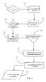
- FIG. 4is a process flow diagram illustrating logical steps for integrated communication center interaction with a WAP user according to an embodiment of the present invention.
- FIG. 1is a general overview of a communications network 9 and communications center 17 integrated with WAP services and enhanced routing functionality according to an embodiment of the present invention.
- Communications network 9comprises an Internet network 11 , a wireless communication network 15 , a connection-orientated switched-telephony (COST) network 13 and a communication center 17 .
- COSTconnection-orientated switched-telephony
- Internet 11may be any type of data packet network (DPN) other than the Internet as long as the appropriate communication protocols are enabled. Examples include-a corporate or private wide area network (WAN), local area network (LAN) and so on.
- WANwide area network
- LANlocal area network
- the Internet networkis chosen in this example as a preferred medium because of a large public-access characteristic, which lends practicality in the practice of the present invention.
- An Internet backbone 25is illustrated within Internet 11 and is intended to represent the many connection points, lines and sub-nets making up the Internet network as a whole in a global sense.
- Two WEB servers (WS) 19 and (WS) 21are illustrated within Internet 11 and shown connected to backbone 25 , representing the wide assortment of Internet-connected servers in the Internet domain.
- Servers 19 and 21represent WEB-based services such as, perhaps a banking service and an airline service. There are many variant possibilities.
- Servers 19 and 21are enabled to serve electronic information pages termed WEB pages in the art as well as provide interactive services such as ordering products, booking airline flights, banking services, or any other services provided by the server hosting enterprises.
- Servers 19 and 21are assumed in this example to be hosted by communication center 17 .
- WEB-services provided by servers 19 and 21are, as known in the art, available to users operating appropriate Internet-enabled appliances and software and having an on-line connection.
- the most common method for on-line access to servers 19 and 21is through a personal computer connected to the Internet through telephone trunks and an Internet service provider (ISP) and having network navigation software (WEB browser).
- Servers 19 and 21serve WEB-pages composed typically in hyper-text-markup language (HTML) or a variation thereof, which is standardized for network data transmission and device display parameters.
- HTMLhyper-text-markup language
- WAP-SP 23A WAP service provider (WAP-SP) 23 is provided within Internet 11 and shown connected to backbone 25 .
- WAP-SP 23is an enhanced proxy server that, among other things, functions as an Interface to users accessing the Internet through WAP-enabled wireless communication devices.
- WAP device 29illustrated within wireless network 15 .
- WAP-SP 23is dedicated to enabling Internet navigation and data transmission between servers 19 and 21 and an exemplary user operating WAP-enabled device 29 .
- Network 15represents an exemplary wireless network that is available to a specific WAP device or a variety of WAP devices.
- Network 15may be a cellular network supporting a number of communication technologies such as code division multiple access (CDMA), time division multiple access (TDMA), global service mobile (GSM), and so on.
- CDMAcode division multiple access
- TDMAtime division multiple access
- GSMglobal service mobile
- WAP-enabled device 29 illustrated within network 15represents any one of a varied lot of different WAP-enabled devices that may be used to access Internet 11 .
- device 29is a laptop computer, however, cell phones, fixed wireless telephones, paging devices, palm computers, and a host of other devices may also be WAP-enabled Internet-capable appliances.
- Dotted double-arrow 27represents an exemplary wireless data-connection between device 29 and WAP-SP 23 .
- COST network 13represents, in this example, a well-known public-switch-telephone-network (PSTN).
- PSTNpublic-switch-telephone-network
- private or corporate telephony networksmay also be used to practice the present invention.
- the inventorchooses the PSTN network because of its large public-access characteristic, which lends to practicality of the present invention.
- Network 13comprises a service control point (SCP) 37 , a network-level telephony switch (SW) 35 , and a CTI processor running an instance of transaction server/statistical server (TS/STAT) 45 (known to the inventor).
- SCPservice control point
- SWnetwork-level telephony switch
- TS/STATtransaction server/statistical server
- Network 13is assumed to further contain a host of other telephony-related equipment such as data routers, network bridges and so on. However, the inventor deems the equipment illustrated herein is adequate for explaining the present invention.
- SCP 37is a computerized facility that controls certain aspects of call routing at switch 35 such as routing 1-800 and 1-900 calls arriving at switch 35 .
- SCP 37is illustrated as connected to switch 35 by a data link.
- Switch 35may be an ACD type or other type of available telephony switching apparatus as are generally known in the art.
- TS/STAT 45is an enhanced CTI routine adapted to provide executable network-level-routing intelligence to switch 35 .
- enhanced “agent level routing” routinesare provided by TS/STAT 45 in some embodiments of the invention. Capabilities such as routing based on agent skill, agent availability, statistical routing, priority routing, and others may be attributed to switch 35 by virtue of the addition of TS/STAT 45 .
- the equipment group exemplified by switch 35 , SCP 37 and processor 45represents “state of the art” CTI telephony capabilities attributed to the “network level” as known to the inventor.
- An equipment grouping similar to that represented in network 13is illustrated as residing within communication center 17 and connected to the aforementioned network-equipment grouping.
- the second groupingcomprises a central telephony switch (SW) 47 , and a CTI processor 49 running an instance of TS/STAT server.
- Processor 49is connected to switch 47 by a CTI link.
- Processor 49is connected to processor 45 in network 13 by a separate digital data network 39 .
- Telephony switch 47is connected to switch 35 in network 13 by at least one COST telephony trunk 41 .
- Enhanced routing routines provided by TS/STAT instances 49 and 45allow for agent level routing from the network level as previously described.
- Data network 39represents a data network for communication between instances of TS/STAT and for passing other digital data.
- a plurality of agent workstations, station 55 , station 57 , and station 59are illustrated within communication center 17 .
- Each agent workstationhas therein a telephone and a personal computer/video display unit (PC/VDU) as exemplified herein with telephone 61 and PC/VDU 67 comprising station 55 .
- Station 57has telephone 63 and PC/VDU 69 .
- Station 59has telephone 65 and PC/VDU 71 .
- each station 55 - 59is identical in illustration. However, there may be differences in actual equipment employed with respect to agent stations such that they may not be identical to each other. It is assumed at least that each station will have a computer terminal and a telephone.
- Stations 55 - 59are each connected to a LAN 53 by respective LAN connections (one at each station).
- LAN 53 in this embodimentis adapted for internal communication and Internet communication. Therefore, LAN 53 may be considered as a sub-net of network 11 .
- Agent telephones 61 - 65are connected to central switch 47 by internal COST wiring 51 .
- telephones 61 - 65may be adapted as data network telephony (DNT)-capable telephones by provision of data connections and integration to respective PC/VDU's 67 - 71 as illustrated.
- telephones 61 - 65may be used for either COST or DNT telephony depending on demand within center 17 .
- An IPT router 33is provided within center 17 and adapted to receive incoming DNT communication events. Router 33 is connected to backbone 25 by an Internet access line 31 .
- a customer information system (CIS) server 48is illustrated within center 17 and connected to LAN 53 .
- CIS server 48is adapted to contain and serve information about customers such as account histories, personal information, and the like. Data stored in server 48 is accessible through LAN 53 and is available to any requesting agent operating one of LAN connected stations 55 - 59 .
- Such customer information systemsare known in the art and common in LAN-capable communication centers.
- incoming COST calls from network 13may be routed to switch 47 and are internally routed to agent's telephones 61 - 65 over wiring 51 .
- DNT communicationmay also be received by agent telephones 61 - 65 .
- IPT switch 33is adapted for routing DNT communication including but not limited to IP telephony, e-mail, video mail, chat events, and so on.
- IPT switch 33is connected to backbone 25 by an Internet access line 31 , which facilitates a continuous network connection in a preferred embodiment.
- Communication center 17is a dual-capable center in this example, however a COST-only or DNT-only center may also practice the present invention.
- WAP-SP 23is adapted as a software-enhanced, WAP-enabled proxy server with COST and DNT telecommunication capabilities.
- CTI and DNT communication and routing software capabilitiesare provided by a processor 50 running an instance of TS/STAT as described with telephony switches 35 in network 13 and 47 in center 17 .
- Enhancing softwareis indicated by SW 40 in FIG. 1 . It should be apparent that software functions may be provided by software executing on server WAP-SP 23 or on T-Server 50 , or on both.
- Hardware and software dedicated to facilitating out-bound call-dialingis provided to enable WAP-SP 23 to initiate and facilitate telecommunication events on behalf of users operating WAP-enabled devices such as laptop 29 .
- WAP-SP 23has a COST trunk 24 connected thereto and also connected to telephony switch 35 in COST network 13 .
- WAP-SP 23is therefore enabled to initiate calls into standard telephony networks and equipment from its Internet location.
- WAP-SP 24by virtue of being an Internet-connected server may also, with suitable software place DNT calls on the Internet backbone.
- WAP-SP 23dials the provided number and establishes a COST connection through trunk 24 to switch 35 , which is connected through trunk 41 to a routing point in switch 47 . From switch 47 , the call is routed internally over wiring 51 to the appropriate station 55 - 59 initiating a ringing event on the appropriate telephone 61 - 65 .
- WAP-SP 23is further adapted to manage data about users and store such data on behalf of users based on prior knowledge and agreement between users and the enterprise hosting the WAP-SP proxy service.
- Data about users that is stored at WAP-SP 23may include but is not limited to user-personal data, user WEB-site data, account information, transaction histories, credit card numbers, or any other type of transferable data.
- WAP-SP 23may store data about users internally or on any connected data repository (data storage facility not shown) as is generally known in the art of storing data.
- WAP-SPmay initiate or facilitate a COST call to one of agents operating within center 17 as described above.
- server 23may also access stored data about a user placing the call, and send it to a same agent (receiving COST call) over Internet access line 31 to IPT switch 33 .
- IPT switch 33From IPT switch 33 , the data, keyed to the routing point ID of the COST call placed, is routed internally over LAN 53 to the target agent.
- WAP-SP 23may initiate an IPNT call on behalf of a user wherein additional data about the user placing the call may be merged with and sent with the call over line 31 to switch 33 , and then be routed over LAN 53 to a suitable agent.
- Processors 45 and 49enable intelligent routing decisions to be made at network level (COST network) with regard to callers calling center 17 from anywhere within COST network 13 or from any PC connected to Internet 11 .
- DNT to COST connectionsmay be accomplished with the aid of network-bridging techniques, (not detailed in this example), but known to the inventor. In a background sense, such enhancements are available and known to the inventor.
- a DNT/COST network bridgemay be available to both WEB servers 19 and 21 such that DNT callers connected to Internet 11 may place a COST call to center 17 while visiting either server. The call would be initiated at server 19 or 21 and be routed through the bridge to switch 35 in network 13 for further routing.
- WAP-SP 23users operating low-bandwidth devices, which are WAP compliant, may now enjoy much of the same enhancement in call routing and quality of service that standard COST or (to a lesser extent) Internet-based callers enjoy. This is accomplished by the ability to place a call through WAP-SP 23 , enhanced by software 40 , and have additional data designed to enhance service to the caller forwarded to the ultimate call destination via separate or the same routing path.
- WAP-SP 23is enhanced for intelligent data routing according to the present invention through the extension of TS/STAT capability as exemplified by connected processor 50 and an extension by separate data network 39 , which may be used to pass digital data.
- data network 39interconnects all of the CTI servers in the overall network. This enhancement along with added dialing capabilities, data profiling services, and WAP functionality, provide users operating WAP devices with several abilities not available in prior art WAP communication services.
- additional data sent over DNT connectionsmay be tagged with the same routing instructions as a COST call in progress and then sent by varied data routes. Therefore, an agent operating within communication center 17 may receive a COST call from a WAP user and also receive a screen-pop containing additional data related to the call.
- the additional data transfersmay be brokered by proxy according to prior agreement between WAP users and the service. For example, if a user operating device 29 places a COST call to an agent working at station 55 , any additional data transferred from WAP-SP 23 over access line 31 to IPT 33 would be routed to station 55 .
- data network 39may also be used to pass the additional data instead of using the traditional Internet backbone 25 and access line 31 .
- an IPT data-routerwould be required to receive the data before routing it to the appropriate agent over LAN 53 .
- a user operating device 29is visiting WEB service 21 to perform an on-line transaction, he may need to contact an agent within center 17 for assistance.
- An IPT callmay be initiated from server 21 to IPT 33 .
- TS/STAT 43communicates with TS/STAT 50 to advise WAP-SP 23 how best to route the IPT call and additional data about the call according to current agent status within center 17 .
- TS/STAT processors and network 39into network 9 enables intelligent call routing and passing of related data using a greater number of paths to the ultimate destination. More detail about various routing options is provided below.
- FIG. 2is a block diagram illustrating various interaction paths or routes of communication possible (and that may or may not be implemented) between WAP users and communication center 17 according to an embodiment of the present invention.
- This examplegenerally follows the physical data paths and equipment connections illustrated in FIG. 1 above.
- One with skill in the artwill be able to relate the routing and data-path options presented in this example with the physical network described in FIG. 1 and with added connections not illustrated in FIG. 1 but known to be possible in the art.
- WAP IWAP I
- WAP IIWAP II
- WAP IIIThree dotted double-arrows also labeled I-III represent wireless links from respective devices I-III to WAP-SP 23 within Internet domain 11 .
- Each WAP device and the corresponding arrowsrepresent at least one routing option made possible by the methods and apparatus of the present invention.
- WAP Iwireless connection I is established between WAP I and WAPSP 23 .
- WAP Iis a personal communication device, it has a unique ID-set.
- a user operating WAP Imust log-in to WAP-SP 23 with (typically) a user name and password pair for authentication purposes. This is to protect the secure nature of the operating environment wherein user data may include personal data.
- WAP Iis cleared to browse Internet 11 .
- WAP-SP 23manages profile data on behalf of users as was described in FIG. 1 .
- This datais illustrated by a dotted rectangle labeled “profile”.
- the deviceis being used to browse contents at WEB-server 19 as is illustrated by the double arrow labeled I.
- the accompanying dotted arrowrepresents profile data forwarded to WEB server 19 by WAP-SP 23 .
- This datais related to the type of business being conducted with server 19 and may or may not be required depending on the type of transaction.
- a COST callis initiated by WAP I to an agent operating within center 17 , which hosts server 19 .
- the reason for the COST call requestmay be that a user requires live assistance in completing a WEB-based transaction.
- an interactive link enabling COST communication to center 17is provided within server 19 embedded in an electronic WEB page as is known in the art.
- the COST callis made through an appropriate network bridge to switch 35 in COST domain 13 .
- WEB server 19forwards additional data about the call either to COST equipment grouping ( 35 ), which in this case would be enhanced with a data connection to Internet 11 , or over backbone 25 and line 31 to IPT 33 .
- COST equipment grouping35
- WS 19is hosted by center 17 , the latter-mentioned route for sending additional data (backbone 25 and access line 31 FIG. 1) is appropriate.
- the ultimate destination for the COST call and the additional digital datais pre-known such that when the COST call arrives at center 17 , it may be matched with the additional data (tagged to the call) sent to IPT 33 within the center. In most cases, the digital data will arrive at the same time or ahead of the call.
- call center sharing server 19If there is more than one call center sharing server 19 then an Internet connection must exist between network 11 and COST equipment ( 35 ) so that the additional data can be routed in parallel with the COST call as is illustrated in this example. In the case of more than one center, determination for which center to route the call to will be made in COST domain 13 . Ultimately, call I and the additional data are routed in parallel or with digital data arriving by a separate route to the appropriate receiving equipment within center 17 .
- Additional data related to call Imay also be passed to center 17 through separate network 39 of FIG. 1 .
- an Internet connectionmust exist between Internet 11 and COST equipment ( 35 ). Additional data may at that point be passed over network 39 to LAN 53 .
- an IPT switchwould be added to receive the data for routing purposes.
- WAP IIis logged on to WAP-SP 23 as illustrated by a double arrow II.
- a second double arrow IIillustrates that WAP II is accessing WEB-service 21 .
- WAP-SP 23passes additional profile data related to a user's business at server 21 over backbone 25 to server 21 .
- a user visiting server 21may decide to initiate a DNT call to center 17 to enlist live aid with his or her WEB-based transaction.
- the DNT call and associated dataare passed over backbone 25 and line 31 to IPT 33 within center 17 .
- the data and callare routed internally over LAN 53 to one of stations 55 - 59 (FIG. 1 ).
- intelligent routing by virtue of processor 43is only available for internal routing to a LAN-connected agent. This is because WEB server 21 is not enhanced with TS/STAT.
- WAP IIIshows two additional routing options. For example, WAP III connects to WAP-SP 23 via wireless link III as illustrated. After successful log-on, a user desires to make a direct COST call to center 17 for immediate customer care. A double arrow III beginning within Internet domain 11 and progressing into COST domain 13 illustrates this scenario. In this case, WAP-SP 23 is enhanced with processor 50 running an instance of TS/STAT wherein processor 50 is connected by network 39 to processor 45 in COST network 13 . Therefore, the COST call may arrive over trunk 24 (FIG. 1) while the additional profile data travels in parallel over network 39 . Full intelligent routing capabilities are possible.
- Parallel routingis also available between COST domain 13 and center 17 by virtue of trunk 41 and network 39 (FIG. 1 ). Again, a means for internally routing the digital data would be provided between processor 49 and LAN 53 . In one embodiment, processor 49 may be additionally enhanced for routing the additional data over LAN 53 (FIG. 1) to the target agent.
- WAP IIIplacing a direct DNT call from WAPSP 23 to center 17 as illustrated by the double arrow III placed between server 23 and IPT 33 (DNT) within center 17 .
- DNTdirect DNT call
- a DNT callmay be routed over backbone 25 to line 31 while the additional data is passed over network 39 .
- FIG. 3is a block diagram illustrating call/data initialization and transfer capabilities of WAP-SP 23 according to an embodiment of the present invention.
- WAP-SP 23performs several functions and services for WAP users communicating, on network 9 (FIG. 1 ).
- One of importance to the present inventionis the function of enabling telephony connections and data transfer capability for users who are engaged in a third-party transaction.
- WAP-SP 23may be considered to have three basic software layers. These are layer 75 (Initialization Layer), layer 77 (Data Processing Layer), and layer 79 (Communication Maintenance Layer).
- Layer 75comprises a means for identifying a WAP user illustrated herein as a block labeled ( 81 ).
- a directional arrow labeled (WAP CALLER) at the top-center of the diagramillustrates initial user input.
- Means 81may be an authentication process such as noting an identification code for the wireless device used and/or requiring a user name and password for authenticating the user. It is known in the art that wireless devices may be assigned at least temporary network identification codes.
- Interface 83may be used to access any connected data repository that stores data about a user and/or other data that may be used to enhance telecommunication function. In this example, the described data will be assumed to be profile data about a call-requesting user.
- a means for confirming call destination illustrated as block 85is invoked.
- Means 85may be coordinated with means 83 in order to access call lists or supported destination numbers held in storage.
- a means for initializing a user call-request ( 86 )is invoked to request a connection.
- Layer 77begins data processing once a third party grants a call request.
- a means for data acquisition ( 87 )is provided for accessing data determined by rule to be sent along with the call.
- the type of data sent along with a callis determined by pre-agreement between a user and the service.
- personal datais, of course, encrypted for data transmission over a network.
- a secure socket layer (SSL) connectionmay be used for this purpose as is common in the art of Internet data transfer.
- a means for tagging data to a call ( 89 )is provided and adapted to associate data being transferred, in many instances via alternate route from a call, to a call in process. Any known means for accomplishing this process may be employed and many techniques are known in the art of telecommunication. Caller line identity (CLID) and automatic number identification (ANI) are two known methods. Moreover, wireless device ID sets may be employed as well as newly conceived tagging methods.
- CLIDCaller line identity
- ANIautomatic number identification
- wireless device ID setsmay be employed as well as newly conceived tagging methods.
- a means for confirming pre-routing instructionsis invoked for the purpose of verifying planned data routes.
- a COST callwill be in progress and additional data must be sent separately over a data connection.
- Pre-confirming a data routeinvolves network management techniques such as reservation service verification protocol (RSVP), as well as other known conventions.
- RSVPreservation service verification protocol
- Intelligent routing routinesmay also play a part in selecting a data rout for both COST and DNT transactions. Securing optimum data routes for digital transfer is an ongoing process. Therefore, it is conceivable that many associated data packets will arrive at their ultimate destination over variable routes.
- a means for WAP processing 92is provided and adapted for structuring data according to device and network receiving the data. It is important to note here that means 92 is more often invoked for data returning to a WAP user. However, if data transferred with a call is destined to another WAP-compliant device, then outgoing data would be re-structured for the receiving device.
- Layer 79manages ongoing communication and data transfer connections.
- a means for call/data processing ( 93 )is provided for the purpose of coordinating any additional data requirements during an ongoing call. For example, a third party may request data not originally sent by WAP-SP 23 at the time of third-party connection. This provides a means for updating data as required.
- a means for maintaining DNT and data transfer connections ( 95 )is provided and adapted to continually monitor open connections for low bandwidth conditions and to adapt by changing routes where possible.
- a means for receiving data returned during a transaction ( 97 )is provided for the purpose of accepting digital data addressed back to the device of the requesting user. Such data after receipt is processed according to appropriate WAP protocol if required.
- FIG. 4is a process flow diagram illustrating logical steps for integrated communication-center interaction with a WAP user according to an embodiment of the present invention.
- a user connected to a WAP-SP of the present inventionrequests a call be placed.
- the useris authenticated at step 101 . As previously mentioned, this may require both device and user authentication processes for operation on the network.
- a requested call destinationis confirmed.
- applicable profile data(determined by rule and pre-agreement) is extracted for sending with a call.
- the data extracted in step 104is processed for transmission to the call destination confirmed at step 103 .
- datais further processed by tagging the data with call parameters if sent separately, or merged with the call if the call in progress is a DNT call. In some instances of DNT application additional data may still be sent separately from the actual DNT call.
- datais WAP processed according to receiving device and destination network.
- communication and data transfer connectionsare monitored and maintained by the WAP-SP terminal.
- additional data from WAP-SP 23is sent if required or as needed. Return data is also processed accordingly to WAP protocol.
Landscapes
- Engineering & Computer Science (AREA)
- Signal Processing (AREA)
- Computer Networks & Wireless Communication (AREA)
- Computer Security & Cryptography (AREA)
- Business, Economics & Management (AREA)
- Marketing (AREA)
- Data Exchanges In Wide-Area Networks (AREA)
- Mobile Radio Communication Systems (AREA)
- Telephonic Communication Services (AREA)
Abstract
Description
Claims (11)
Priority Applications (7)
| Application Number | Priority Date | Filing Date | Title |
|---|---|---|---|
| US09/549,449US6418146B1 (en) | 1999-12-10 | 2000-04-14 | Integrated communication center functionality for WAP devices |
| PCT/US2000/027984WO2001043410A1 (en) | 1999-12-10 | 2000-10-10 | Integrated communication center functionality for wap devices |
| JP2001542990AJP3820151B2 (en) | 1999-12-10 | 2000-10-10 | Integrated communication center function for WAP devices |
| AU10773/01AAU1077301A (en) | 1999-12-10 | 2000-10-10 | Integrated communication center functionality for wap devices |
| EP00123331AEP1107555A3 (en) | 1999-12-10 | 2000-10-27 | Integrated communication center functionality for WAP devices |
| US10/022,304US20020054579A1 (en) | 1999-12-10 | 2001-12-14 | Integrated communication center functionality for WAP devices |
| US10/074,886US6718366B2 (en) | 1998-02-20 | 2002-02-11 | Method and apparatus for providing media-independent self-help modules within a multimedia communication-center customer interface |
Applications Claiming Priority (2)
| Application Number | Priority Date | Filing Date | Title |
|---|---|---|---|
| US17284899P | 1999-12-10 | 1999-12-10 | |
| US09/549,449US6418146B1 (en) | 1999-12-10 | 2000-04-14 | Integrated communication center functionality for WAP devices |
Related Child Applications (2)
| Application Number | Title | Priority Date | Filing Date |
|---|---|---|---|
| US10/022,304ContinuationUS20020054579A1 (en) | 1999-12-10 | 2001-12-14 | Integrated communication center functionality for WAP devices |
| US10/074,886ContinuationUS6718366B2 (en) | 1998-02-20 | 2002-02-11 | Method and apparatus for providing media-independent self-help modules within a multimedia communication-center customer interface |
Publications (1)
| Publication Number | Publication Date |
|---|---|
| US6418146B1true US6418146B1 (en) | 2002-07-09 |
Family
ID=26868524
Family Applications (2)
| Application Number | Title | Priority Date | Filing Date |
|---|---|---|---|
| US09/549,449Expired - LifetimeUS6418146B1 (en) | 1998-02-20 | 2000-04-14 | Integrated communication center functionality for WAP devices |
| US10/022,304AbandonedUS20020054579A1 (en) | 1999-12-10 | 2001-12-14 | Integrated communication center functionality for WAP devices |
Family Applications After (1)
| Application Number | Title | Priority Date | Filing Date |
|---|---|---|---|
| US10/022,304AbandonedUS20020054579A1 (en) | 1999-12-10 | 2001-12-14 | Integrated communication center functionality for WAP devices |
Country Status (5)
| Country | Link |
|---|---|
| US (2) | US6418146B1 (en) |
| EP (1) | EP1107555A3 (en) |
| JP (1) | JP3820151B2 (en) |
| AU (1) | AU1077301A (en) |
| WO (1) | WO2001043410A1 (en) |
Cited By (42)
| Publication number | Priority date | Publication date | Assignee | Title |
|---|---|---|---|---|
| US20010047427A1 (en)* | 2000-05-19 | 2001-11-29 | Jari Lansio | Data transmission method and arrangement |
| US20020046259A1 (en)* | 1999-12-29 | 2002-04-18 | Glorikian Harry A. | Internet system for connecting client-travelers with geographically-associated data |
| US20020085568A1 (en)* | 2000-12-29 | 2002-07-04 | Oommen Paul P. | WTA based over the air management (OTAM) method and apparatus |
| US20020129136A1 (en)* | 2001-03-08 | 2002-09-12 | Matharu Tarlochan S. | System and method for wap server management using a single console |
| US20030007618A1 (en)* | 2001-07-05 | 2003-01-09 | Jose Guterman | Uploading personal agents to personalize network services |
| US20030046532A1 (en)* | 2001-08-31 | 2003-03-06 | Matthew Gast | System and method for accelerating cryptographically secured transactions |
| US6633635B2 (en) | 1999-12-30 | 2003-10-14 | At&T Corp. | Multiple call waiting in a packetized communication system |
| US6671262B1 (en) | 1999-12-30 | 2003-12-30 | At&T Corp. | Conference server for automatic x-way call port expansion feature |
| US6678265B1 (en) | 1999-12-30 | 2004-01-13 | At&T Corp. | Local number portability database for on-net IP call |
| US6680935B1 (en) | 1999-12-30 | 2004-01-20 | At&T Corp. | Anonymous call rejection |
| US6690675B1 (en) | 1999-12-30 | 2004-02-10 | At&T Corp. | User programmable fail-proof IP hotline/warm-line |
| US6728239B1 (en) | 1999-12-30 | 2004-04-27 | At&T Corp. | Scaleable network server for low cost PBX |
| US20040092266A1 (en)* | 2000-08-11 | 2004-05-13 | Olrik Jakob Christian | Mobile telecommunications data service |
| US6751452B1 (en)* | 2000-05-01 | 2004-06-15 | General Motors Coporation | Internet based vehicle data communication system |
| US6775267B1 (en) | 1999-12-30 | 2004-08-10 | At&T Corp | Method for billing IP broadband subscribers |
| US6775273B1 (en) | 1999-12-30 | 2004-08-10 | At&T Corp. | Simplified IP service control |
| US20040169675A1 (en)* | 1998-09-11 | 2004-09-02 | Beck Christopher Clemmett Macleod | Method and apparatus for providing media-independent self-help modules within a multimedia communication-center customer interface |
| US6816469B1 (en) | 1999-12-30 | 2004-11-09 | At&T Corp. | IP conference call waiting |
| US6826173B1 (en) | 1999-12-30 | 2004-11-30 | At&T Corp. | Enhanced subscriber IP alerting |
| US6889321B1 (en) | 1999-12-30 | 2005-05-03 | At&T Corp. | Protected IP telephony calls using encryption |
| US6891807B2 (en) | 2003-01-13 | 2005-05-10 | America Online, Incorporated | Time based wireless access provisioning |
| US20050138032A1 (en)* | 2003-12-19 | 2005-06-23 | O'rourke Thomas | Network based client-server communications |
| US6917610B1 (en) | 1999-12-30 | 2005-07-12 | At&T Corp. | Activity log for improved call efficiency |
| US6952414B1 (en)* | 2000-09-26 | 2005-10-04 | Advanced Micro Devices, Inc. | Portable internet browser device with cordless phone module and method of operation |
| US20050273489A1 (en)* | 2004-06-04 | 2005-12-08 | Comverse, Ltd. | Multimedia system for a mobile log |
| US7075918B1 (en) | 1999-12-30 | 2006-07-11 | At&T Corp. | BRG with PBX capabilities |
| US7120139B1 (en) | 1999-12-30 | 2006-10-10 | At&T Corp. | Broadband cable telephony network architecture IP ITN network architecture reference model |
| US7940746B2 (en) | 2004-08-24 | 2011-05-10 | Comcast Cable Holdings, Llc | Method and system for locating a voice over internet protocol (VoIP) device connected to a network |
| US9002920B2 (en) | 1998-09-11 | 2015-04-07 | Genesys Telecommunications Laboratories, Inc. | Method and apparatus for extended management of state and interaction of a remote knowledge worker from a contact center |
| US9008075B2 (en) | 2005-12-22 | 2015-04-14 | Genesys Telecommunications Laboratories, Inc. | System and methods for improving interaction routing performance |
| USRE45583E1 (en) | 1999-12-01 | 2015-06-23 | Genesys Telecommunications Laboratories, Inc. | Method and apparatus for providing enhanced communication capability for mobile devices on a virtual private network |
| USRE45606E1 (en) | 1997-02-10 | 2015-07-07 | Genesys Telecommunications Laboratories, Inc. | Call and data correspondence in a call-in center employing virtual restructuring for computer telephony integrated functionality |
| US9286294B2 (en) | 1992-12-09 | 2016-03-15 | Comcast Ip Holdings I, Llc | Video and digital multimedia aggregator content suggestion engine |
| USRE46060E1 (en) | 1997-02-10 | 2016-07-05 | Genesys Telecommunications Laboratories, Inc. | In-band signaling for routing |
| USRE46153E1 (en) | 1998-09-11 | 2016-09-20 | Genesys Telecommunications Laboratories, Inc. | Method and apparatus enabling voice-based management of state and interaction of a remote knowledge worker in a contact center environment |
| US9516171B2 (en) | 1997-02-10 | 2016-12-06 | Genesys Telecommunications Laboratories, Inc. | Personal desktop router |
| US9553755B2 (en) | 1998-02-17 | 2017-01-24 | Genesys Telecommunications Laboratories, Inc. | Method for implementing and executing communication center routing strategies represented in extensible markup language |
| USRE46438E1 (en) | 1999-09-24 | 2017-06-13 | Genesys Telecommunications Laboratories, Inc. | Method and apparatus for data-linking a mobile knowledge worker to home communication-center infrastructure |
| USRE46528E1 (en) | 1997-11-14 | 2017-08-29 | Genesys Telecommunications Laboratories, Inc. | Implementation of call-center outbound dialing capability at a telephony network level |
| US9813641B2 (en) | 2000-06-19 | 2017-11-07 | Comcast Ip Holdings I, Llc | Method and apparatus for targeting of interactive virtual objects |
| US10140433B2 (en) | 2001-08-03 | 2018-11-27 | Comcast Ip Holdings I, Llc | Video and digital multimedia aggregator |
| US10349096B2 (en) | 2001-08-03 | 2019-07-09 | Comcast Ip Holdings I, Llc | Video and digital multimedia aggregator content coding and formatting |
Families Citing this family (10)
| Publication number | Priority date | Publication date | Assignee | Title |
|---|---|---|---|---|
| WO2001091401A2 (en)* | 2000-05-19 | 2001-11-29 | Ztango, Inc. | A system for providing wireless application protocol-based services |
| US20020048283A1 (en)* | 2000-06-29 | 2002-04-25 | Ching-Yi Lin | Phone appliance with display screen and methods of using the same |
| US7380007B1 (en)* | 2000-06-30 | 2008-05-27 | Aol Llc, A Delaware Limited Liability Company | Automatic user session |
| CA2318287A1 (en)* | 2000-08-30 | 2002-02-28 | Aria Solutions Inc. | System integrated framework |
| US20020052199A1 (en)* | 2000-10-30 | 2002-05-02 | Mukesh Sundaram | Call center management for wireless access network |
| EP1396157A1 (en)* | 2001-06-13 | 2004-03-10 | Siemens Aktiengesellschaft | Programming interfaces for an exchange centre |
| US10173008B2 (en)* | 2002-01-29 | 2019-01-08 | Baxter International Inc. | System and method for communicating with a dialysis machine through a network |
| US8526978B2 (en)* | 2003-10-29 | 2013-09-03 | Interdigital Technology Corporation | Method and apparatus for efficiently delivering supplementary services to multi-technology capable wireless transmit/receive units |
| US20060274724A1 (en)* | 2005-06-02 | 2006-12-07 | Agere Systems Inc. | Method of providing a parallel voice and data connection with a call center and a device for the same |
| CN113570324A (en)* | 2021-06-08 | 2021-10-29 | 北京声智科技有限公司 | Outbound call flow editing method, device, electronic device and storage medium |
Citations (10)
| Publication number | Priority date | Publication date | Assignee | Title |
|---|---|---|---|---|
| US5751707A (en)* | 1995-06-19 | 1998-05-12 | Bell Atlantic Network Services, Inc. | AIN interaction through wireless digital video network |
| US5751706A (en)* | 1996-06-05 | 1998-05-12 | Cignal Global Communications, Inc. | System and method for establishing a call telecommunications path |
| US5841854A (en)* | 1994-02-16 | 1998-11-24 | Priority Call Management, Inc. | Wireless telephone integration system and method for call centers and workgroups |
| US5920621A (en)* | 1996-04-15 | 1999-07-06 | Mci Communications Corporation | System and method for distributing calls to customer service operators based on automatic determination of operator availability |
| US6055307A (en)* | 1996-06-28 | 2000-04-25 | At&T Corp. | System and method for selecting agent destinations and monitoring calls made to network customers |
| US6088340A (en)* | 1998-06-23 | 2000-07-11 | Motorola, Inc. | Method and apparatus in a wireless communication system for controlling a display of template data by a protable subscriber unit |
| US6094479A (en)* | 1997-05-06 | 2000-07-25 | Telefonaktiebolaget Lm Ericsson | Computer telephony integration gateway |
| US6185535B1 (en)* | 1998-10-16 | 2001-02-06 | Telefonaktiebolaget Lm Ericsson (Publ) | Voice control of a user interface to service applications |
| US6275693B1 (en)* | 1999-11-22 | 2001-08-14 | Motorola, Inc. | Method and apparatus for performing bearer independent wireless application service provisioning |
| US6304898B1 (en)* | 1999-10-13 | 2001-10-16 | Datahouse, Inc. | Method and system for creating and sending graphical email |
Family Cites Families (3)
| Publication number | Priority date | Publication date | Assignee | Title |
|---|---|---|---|---|
| US5546452A (en)* | 1995-03-02 | 1996-08-13 | Geotel Communications Corp. | Communications system using a central controller to control at least one network and agent system |
| CA2173304C (en)* | 1995-04-21 | 2003-04-29 | Anthony J. Dezonno | Method and system for establishing voice communications using a computer network |
| US5884032A (en)* | 1995-09-25 | 1999-03-16 | The New Brunswick Telephone Company, Limited | System for coordinating communications via customer contact channel changing system using call centre for setting up the call between customer and an available help agent |
- 2000
- 2000-04-14USUS09/549,449patent/US6418146B1/ennot_activeExpired - Lifetime
- 2000-10-10AUAU10773/01Apatent/AU1077301A/ennot_activeAbandoned
- 2000-10-10JPJP2001542990Apatent/JP3820151B2/ennot_activeExpired - Lifetime
- 2000-10-10WOPCT/US2000/027984patent/WO2001043410A1/enactiveApplication Filing
- 2000-10-27EPEP00123331Apatent/EP1107555A3/ennot_activeWithdrawn
- 2001
- 2001-12-14USUS10/022,304patent/US20020054579A1/ennot_activeAbandoned
Patent Citations (10)
| Publication number | Priority date | Publication date | Assignee | Title |
|---|---|---|---|---|
| US5841854A (en)* | 1994-02-16 | 1998-11-24 | Priority Call Management, Inc. | Wireless telephone integration system and method for call centers and workgroups |
| US5751707A (en)* | 1995-06-19 | 1998-05-12 | Bell Atlantic Network Services, Inc. | AIN interaction through wireless digital video network |
| US5920621A (en)* | 1996-04-15 | 1999-07-06 | Mci Communications Corporation | System and method for distributing calls to customer service operators based on automatic determination of operator availability |
| US5751706A (en)* | 1996-06-05 | 1998-05-12 | Cignal Global Communications, Inc. | System and method for establishing a call telecommunications path |
| US6055307A (en)* | 1996-06-28 | 2000-04-25 | At&T Corp. | System and method for selecting agent destinations and monitoring calls made to network customers |
| US6094479A (en)* | 1997-05-06 | 2000-07-25 | Telefonaktiebolaget Lm Ericsson | Computer telephony integration gateway |
| US6088340A (en)* | 1998-06-23 | 2000-07-11 | Motorola, Inc. | Method and apparatus in a wireless communication system for controlling a display of template data by a protable subscriber unit |
| US6185535B1 (en)* | 1998-10-16 | 2001-02-06 | Telefonaktiebolaget Lm Ericsson (Publ) | Voice control of a user interface to service applications |
| US6304898B1 (en)* | 1999-10-13 | 2001-10-16 | Datahouse, Inc. | Method and system for creating and sending graphical email |
| US6275693B1 (en)* | 1999-11-22 | 2001-08-14 | Motorola, Inc. | Method and apparatus for performing bearer independent wireless application service provisioning |
Cited By (76)
| Publication number | Priority date | Publication date | Assignee | Title |
|---|---|---|---|---|
| US9286294B2 (en) | 1992-12-09 | 2016-03-15 | Comcast Ip Holdings I, Llc | Video and digital multimedia aggregator content suggestion engine |
| US9516171B2 (en) | 1997-02-10 | 2016-12-06 | Genesys Telecommunications Laboratories, Inc. | Personal desktop router |
| USRE45606E1 (en) | 1997-02-10 | 2015-07-07 | Genesys Telecommunications Laboratories, Inc. | Call and data correspondence in a call-in center employing virtual restructuring for computer telephony integrated functionality |
| USRE46060E1 (en) | 1997-02-10 | 2016-07-05 | Genesys Telecommunications Laboratories, Inc. | In-band signaling for routing |
| USRE46243E1 (en) | 1997-02-10 | 2016-12-20 | Genesys Telecommunications Laboratories, Inc. | In-band signaling for routing |
| USRE46521E1 (en) | 1997-09-30 | 2017-08-22 | Genesys Telecommunications Laboratories, Inc. | Method and apparatus for extended management of state and interaction of a remote knowledge worker from a contact center |
| USRE46528E1 (en) | 1997-11-14 | 2017-08-29 | Genesys Telecommunications Laboratories, Inc. | Implementation of call-center outbound dialing capability at a telephony network level |
| US9553755B2 (en) | 1998-02-17 | 2017-01-24 | Genesys Telecommunications Laboratories, Inc. | Method for implementing and executing communication center routing strategies represented in extensible markup language |
| US9350808B2 (en) | 1998-09-11 | 2016-05-24 | Alcatel Lucent | Method for routing transactions between internal and external partners in a communication center |
| US8971216B2 (en) | 1998-09-11 | 2015-03-03 | Alcatel Lucent | Method for routing transactions between internal and external partners in a communication center |
| US10218848B2 (en) | 1998-09-11 | 2019-02-26 | Genesys Telecommunications Laboratories, Inc. | Method and apparatus for extended management of state and interaction of a remote knowledge worker from a contact center |
| US9002920B2 (en) | 1998-09-11 | 2015-04-07 | Genesys Telecommunications Laboratories, Inc. | Method and apparatus for extended management of state and interaction of a remote knowledge worker from a contact center |
| USRE46153E1 (en) | 1998-09-11 | 2016-09-20 | Genesys Telecommunications Laboratories, Inc. | Method and apparatus enabling voice-based management of state and interaction of a remote knowledge worker in a contact center environment |
| USRE46387E1 (en) | 1998-09-11 | 2017-05-02 | Genesys Telecommunications Laboratories, Inc. | Method and apparatus for extended management of state and interaction of a remote knowledge worker from a contact center |
| US20040169675A1 (en)* | 1998-09-11 | 2004-09-02 | Beck Christopher Clemmett Macleod | Method and apparatus for providing media-independent self-help modules within a multimedia communication-center customer interface |
| USRE46438E1 (en) | 1999-09-24 | 2017-06-13 | Genesys Telecommunications Laboratories, Inc. | Method and apparatus for data-linking a mobile knowledge worker to home communication-center infrastructure |
| USRE46457E1 (en) | 1999-09-24 | 2017-06-27 | Genesys Telecommunications Laboratories, Inc. | Method and apparatus for data-linking a mobile knowledge worker to home communication-center infrastructure |
| USRE45583E1 (en) | 1999-12-01 | 2015-06-23 | Genesys Telecommunications Laboratories, Inc. | Method and apparatus for providing enhanced communication capability for mobile devices on a virtual private network |
| US20020046259A1 (en)* | 1999-12-29 | 2002-04-18 | Glorikian Harry A. | Internet system for connecting client-travelers with geographically-associated data |
| US9299088B2 (en) | 1999-12-29 | 2016-03-29 | Cufer Asset Ltd. L.L.C. | Internet system for connecting client-travelers with geographically-associated data |
| US20070083539A1 (en)* | 1999-12-29 | 2007-04-12 | Glorikian Harry A | Internet System for Connecting Client-Travelers with Geographically-Associated Data |
| US8725120B2 (en) | 1999-12-29 | 2014-05-13 | Crystal Development Consulting Services L.L.C. | Internet system for connecting client-travelers with geographically-associated data |
| US6826173B1 (en) | 1999-12-30 | 2004-11-30 | At&T Corp. | Enhanced subscriber IP alerting |
| US6680935B1 (en) | 1999-12-30 | 2004-01-20 | At&T Corp. | Anonymous call rejection |
| US6917610B1 (en) | 1999-12-30 | 2005-07-12 | At&T Corp. | Activity log for improved call efficiency |
| US6678265B1 (en) | 1999-12-30 | 2004-01-13 | At&T Corp. | Local number portability database for on-net IP call |
| US6671262B1 (en) | 1999-12-30 | 2003-12-30 | At&T Corp. | Conference server for automatic x-way call port expansion feature |
| US7075918B1 (en) | 1999-12-30 | 2006-07-11 | At&T Corp. | BRG with PBX capabilities |
| US6690675B1 (en) | 1999-12-30 | 2004-02-10 | At&T Corp. | User programmable fail-proof IP hotline/warm-line |
| US6816469B1 (en) | 1999-12-30 | 2004-11-09 | At&T Corp. | IP conference call waiting |
| US7120139B1 (en) | 1999-12-30 | 2006-10-10 | At&T Corp. | Broadband cable telephony network architecture IP ITN network architecture reference model |
| US6728239B1 (en) | 1999-12-30 | 2004-04-27 | At&T Corp. | Scaleable network server for low cost PBX |
| US6633635B2 (en) | 1999-12-30 | 2003-10-14 | At&T Corp. | Multiple call waiting in a packetized communication system |
| US6775267B1 (en) | 1999-12-30 | 2004-08-10 | At&T Corp | Method for billing IP broadband subscribers |
| US6889321B1 (en) | 1999-12-30 | 2005-05-03 | At&T Corp. | Protected IP telephony calls using encryption |
| US8711735B2 (en) | 1999-12-30 | 2014-04-29 | At&T Intellectual Property, Ii, L.P. | Personal IP toll-free number |
| US6775273B1 (en) | 1999-12-30 | 2004-08-10 | At&T Corp. | Simplified IP service control |
| US6751452B1 (en)* | 2000-05-01 | 2004-06-15 | General Motors Coporation | Internet based vehicle data communication system |
| US7096267B2 (en)* | 2000-05-19 | 2006-08-22 | Nokia Mobile Phones, Ltd. | Data transmission method and arrangement using method calls |
| US20010047427A1 (en)* | 2000-05-19 | 2001-11-29 | Jari Lansio | Data transmission method and arrangement |
| US9813641B2 (en) | 2000-06-19 | 2017-11-07 | Comcast Ip Holdings I, Llc | Method and apparatus for targeting of interactive virtual objects |
| US7274927B2 (en)* | 2000-08-11 | 2007-09-25 | Nokia Corporation | Mobile telecommunications data service |
| US20040092266A1 (en)* | 2000-08-11 | 2004-05-13 | Olrik Jakob Christian | Mobile telecommunications data service |
| US6952414B1 (en)* | 2000-09-26 | 2005-10-04 | Advanced Micro Devices, Inc. | Portable internet browser device with cordless phone module and method of operation |
| US6799203B2 (en)* | 2000-12-29 | 2004-09-28 | Nokia Mobile Phones Ltd. | WTA based over the air management (OTAM) method and apparatus |
| US8176165B2 (en) | 2000-12-29 | 2012-05-08 | Nokia Mobile Phones Oy | WTA based over the air management (OTAM) method and apparatus |
| US20020085568A1 (en)* | 2000-12-29 | 2002-07-04 | Oommen Paul P. | WTA based over the air management (OTAM) method and apparatus |
| US20050021681A1 (en)* | 2000-12-29 | 2005-01-27 | Oommen Paul P. | WTA based over the air management (OTAM) method and apparatus |
| US7170864B2 (en)* | 2001-03-08 | 2007-01-30 | Bmc Software, Inc. | System and method for WAP server management using a single console |
| US20020129136A1 (en)* | 2001-03-08 | 2002-09-12 | Matharu Tarlochan S. | System and method for wap server management using a single console |
| US20030007618A1 (en)* | 2001-07-05 | 2003-01-09 | Jose Guterman | Uploading personal agents to personalize network services |
| US7093009B2 (en)* | 2001-07-05 | 2006-08-15 | Intel Corporation | Uploading personal agents to personalize network services |
| US10140433B2 (en) | 2001-08-03 | 2018-11-27 | Comcast Ip Holdings I, Llc | Video and digital multimedia aggregator |
| US10349096B2 (en) | 2001-08-03 | 2019-07-09 | Comcast Ip Holdings I, Llc | Video and digital multimedia aggregator content coding and formatting |
| US20030046532A1 (en)* | 2001-08-31 | 2003-03-06 | Matthew Gast | System and method for accelerating cryptographically secured transactions |
| USRE46538E1 (en) | 2002-10-10 | 2017-09-05 | Genesys Telecommunications Laboratories, Inc. | Method and apparatus for extended management of state and interaction of a remote knowledge worker from a contact center |
| US7463596B2 (en) | 2003-01-13 | 2008-12-09 | Aol Llc | Time based wireless access provisioning |
| US7911979B2 (en) | 2003-01-13 | 2011-03-22 | Tarquin Consulting Co., Llc | Time based access provisioning system and process |
| US7177285B2 (en) | 2003-01-13 | 2007-02-13 | America Online, Incorporated | Time based wireless access provisioning |
| US6891807B2 (en) | 2003-01-13 | 2005-05-10 | America Online, Incorporated | Time based wireless access provisioning |
| US20070135060A1 (en)* | 2003-01-13 | 2007-06-14 | Roskind James A | Time based wireless access provisioning |
| US20090168667A1 (en)* | 2003-01-13 | 2009-07-02 | Roskind James A | Time based access provisioning system and process |
| US20050138032A1 (en)* | 2003-12-19 | 2005-06-23 | O'rourke Thomas | Network based client-server communications |
| US20050273489A1 (en)* | 2004-06-04 | 2005-12-08 | Comverse, Ltd. | Multimedia system for a mobile log |
| US9648644B2 (en) | 2004-08-24 | 2017-05-09 | Comcast Cable Communications, Llc | Determining a location of a device for calling via an access point |
| US7940746B2 (en) | 2004-08-24 | 2011-05-10 | Comcast Cable Holdings, Llc | Method and system for locating a voice over internet protocol (VoIP) device connected to a network |
| US8724522B2 (en) | 2004-08-24 | 2014-05-13 | Comcast Cable Holdings, Llc | Method and system for locating a voice over internet protocol (VoIP) device connected to a network |
| US9055550B1 (en) | 2004-08-24 | 2015-06-09 | Comcast Cable Holdings, Llc | Locating a voice over packet (VoP) device connected to a network |
| US10070466B2 (en) | 2004-08-24 | 2018-09-04 | Comcast Cable Communications, Llc | Determining a location of a device for calling via an access point |
| US9036626B2 (en) | 2004-08-24 | 2015-05-19 | Comcast Cable Holdings, Llc | Method and system for locating a voice over internet protocol (VOIP) device connected to a network |
| US9049132B1 (en) | 2004-08-24 | 2015-06-02 | Comcast Cable Holdings, Llc | Locating a voice over packet (VoP) device connected to a network |
| US10517140B2 (en) | 2004-08-24 | 2019-12-24 | Comcast Cable Communications, Llc | Determining a location of a device for calling via an access point |
| US11252779B2 (en) | 2004-08-24 | 2022-02-15 | Comcast Cable Communications, Llc | Physical location management for voice over packet communication |
| US11956852B2 (en) | 2004-08-24 | 2024-04-09 | Comcast Cable Communications, Llc | Physical location management for voice over packet communication |
| US9854006B2 (en) | 2005-12-22 | 2017-12-26 | Genesys Telecommunications Laboratories, Inc. | System and methods for improving interaction routing performance |
| US9008075B2 (en) | 2005-12-22 | 2015-04-14 | Genesys Telecommunications Laboratories, Inc. | System and methods for improving interaction routing performance |
Also Published As
| Publication number | Publication date |
|---|---|
| AU1077301A (en) | 2001-06-18 |
| WO2001043410A1 (en) | 2001-06-14 |
| US20020054579A1 (en) | 2002-05-09 |
| EP1107555A2 (en) | 2001-06-13 |
| JP2003516672A (en) | 2003-05-13 |
| JP3820151B2 (en) | 2006-09-13 |
| EP1107555A3 (en) | 2004-01-21 |
Similar Documents
| Publication | Publication Date | Title |
|---|---|---|
| US6418146B1 (en) | Integrated communication center functionality for WAP devices | |
| US7277536B2 (en) | Method and apparatus for routing calls by proxy using virtual transaction servers in a multi-tennant communication center | |
| US6389028B1 (en) | Method and apparatus for providing estimated response-wait-time displays for data network-based inquiries to a communication center | |
| US7289493B1 (en) | System and method for providing location independent voice communications continuity through disasters | |
| US9100414B2 (en) | Method and apparatus for providing a reliable voice extensible markup language service | |
| ES2255657T3 (en) | APPARATUS AND METHODS TO IMPROVE THE CALLING ROUTE TO CALL CENTERS AND INSIDE. | |
| US6226286B1 (en) | Apparatus and method for communication between data network and telecommunication network | |
| JP2003507937A (en) | Contact routing system and method | |
| CA2339921A1 (en) | Point-of-presence call center management system | |
| WO2000044159A1 (en) | A method for serving ip users by graphically-based interaction to agents of a call center | |
| AU728548C (en) | Device and method for communication between a data network and a telecommunications network | |
| US8081623B2 (en) | Packet network based emergency backup telephone system | |
| US7453830B2 (en) | Internet architecture for software based ACD | |
| US6937593B1 (en) | System and method for servicing calls originating via the internet | |
| US8024401B1 (en) | Customer relationship management system with network contact center server configured to control automated web and voice dialogues | |
| JP4545649B2 (en) | A system that facilitates parallel data transfer from a wireless caller to a communication center. | |
| CA2270046C (en) | Device and method for communication between a data network and a telecommunications network | |
| Lautenbacher | Web Call Center: Internet-Enhanced Voice Communication with Coordinated Interworking between PSTN and Internet |
Legal Events
| Date | Code | Title | Description |
|---|---|---|---|
| AS | Assignment | Owner name:GENESYS TELECOMMUNICATIONS LABORATORIES, INC., CAL Free format text:ASSIGNMENT OF ASSIGNORS INTEREST;ASSIGNOR:MILOSLAVSKY, ALEC;REEL/FRAME:010889/0935 Effective date:20000609 | |
| STCF | Information on status: patent grant | Free format text:PATENTED CASE | |
| FEPP | Fee payment procedure | Free format text:PAYOR NUMBER ASSIGNED (ORIGINAL EVENT CODE: ASPN); ENTITY STATUS OF PATENT OWNER: LARGE ENTITY | |
| FPAY | Fee payment | Year of fee payment:4 | |
| FPAY | Fee payment | Year of fee payment:8 | |
| AS | Assignment | Owner name:ALCATEL LUCENT, FRANCE Free format text:ASSIGNMENT OF ASSIGNORS INTEREST;ASSIGNOR:GENESYS TELECOMMUNICATIONS LABORATORIES, INC.;REEL/FRAME:026887/0371 Effective date:20090309 | |
| AS | Assignment | Owner name:GOLDMAN SACHS LENDING PARTNERS LLC, NEW YORK Free format text:SECURITY AGREEMENT;ASSIGNOR:GENESYS TELECOMMUNICATIONS LABORATORIES, INC.;REEL/FRAME:027623/0096 Effective date:20120131 | |
| AS | Assignment | Owner name:GENESYS TELECOMMUNICATIONS LABORATORIES, INC., CAL Free format text:ASSIGNMENT OF ASSIGNORS INTEREST;ASSIGNOR:ALCATEL LUCENT;REEL/FRAME:027687/0686 Effective date:20120130 | |
| AS | Assignment | Owner name:GOLDMAN SACHS BANK USA, NEW YORK Free format text:SECURITY AGREEMENT;ASSIGNOR:GENESYS TELECOMMUNICATIONS LABORATORIES, INC.;REEL/FRAME:029778/0939 Effective date:20130208 Owner name:GENESYS TELECOMMUNICATIONS LABORATORIES, INC., CAL Free format text:RELEASE BY SECURED PARTY;ASSIGNOR:GOLDMAN SACHS LENDING PARTNERS LLC;REEL/FRAME:029778/0060 Effective date:20130208 | |
| AS | Assignment | Owner name:JPMORGAN CHASE BANK, N.A., AS COLLATERAL AGENT, DE Free format text:SECURITY AGREEMENT;ASSIGNORS:GENESYS TELECOMMUNICATIONS LABORATORIES, INC.;ANGEL.COM INCORPORATED;UTOPY, INC.;AND OTHERS;REEL/FRAME:031644/0814 Effective date:20131113 | |
| FPAY | Fee payment | Year of fee payment:12 | |
| AS | Assignment | Owner name:SOUNDBITE COMMUNICATIONS, INC., CALIFORNIA Free format text:PATENT RELEASE (REEL:031644/FRAME:0814);ASSIGNOR:JPMORGAN CHASE BANK, N.A., AS COLLATERAL AGENT;REEL/FRAME:040798/0428 Effective date:20161201 Owner name:UTOPY, INC., CALIFORNIA Free format text:PATENT RELEASE (REEL:031644/FRAME:0814);ASSIGNOR:JPMORGAN CHASE BANK, N.A., AS COLLATERAL AGENT;REEL/FRAME:040798/0428 Effective date:20161201 Owner name:GENESYS TELECOMMUNICATIONS LABORATORIES, INC., AS Free format text:PATENT RELEASE (REEL:031644/FRAME:0814);ASSIGNOR:JPMORGAN CHASE BANK, N.A., AS COLLATERAL AGENT;REEL/FRAME:040798/0428 Effective date:20161201 Owner name:ANGEL.COM INCORPORATED, CALIFORNIA Free format text:PATENT RELEASE (REEL:031644/FRAME:0814);ASSIGNOR:JPMORGAN CHASE BANK, N.A., AS COLLATERAL AGENT;REEL/FRAME:040798/0428 Effective date:20161201 | |
| AS | Assignment | Owner name:BANK OF AMERICA, N.A., AS COLLATERAL AGENT, NORTH CAROLINA Free format text:SECURITY AGREEMENT;ASSIGNORS:GENESYS TELECOMMUNICATIONS LABORATORIES, INC., AS GRANTOR;ECHOPASS CORPORATION;INTERACTIVE INTELLIGENCE GROUP, INC.;AND OTHERS;REEL/FRAME:040815/0001 Effective date:20161201 Owner name:BANK OF AMERICA, N.A., AS COLLATERAL AGENT, NORTH Free format text:SECURITY AGREEMENT;ASSIGNORS:GENESYS TELECOMMUNICATIONS LABORATORIES, INC., AS GRANTOR;ECHOPASS CORPORATION;INTERACTIVE INTELLIGENCE GROUP, INC.;AND OTHERS;REEL/FRAME:040815/0001 Effective date:20161201 | |
| AS | Assignment | Owner name:GENESYS TELECOMMUNICATIONS LABORATORIES, INC., CAL Free format text:CORRECTIVE RELEASE FOR SECURITY INTEREST IN PATENTS ORIGINALLY RECORDED AT REEL/FRAME (029778/0939);ASSIGNOR:JPMORGAN CHASE BANK, N.A., AS SUCCESSOR TO THE ORIGINAL COLLATERAL AGENT GOLDMAN SACHS BANK USA;REEL/FRAME:041821/0209 Effective date:20170223 Owner name:SOUNDBITE COMMUNICATIONS, INC., CALIFORNIA Free format text:CORRECTIVE RELEASE FOR SECURITY INTEREST IN PATENTS ORIGINALLY RECORDED AT REEL/FRAME (029778/0939);ASSIGNOR:JPMORGAN CHASE BANK, N.A., AS SUCCESSOR TO THE ORIGINAL COLLATERAL AGENT GOLDMAN SACHS BANK USA;REEL/FRAME:041821/0209 Effective date:20170223 Owner name:UTOPY, INC., CALIFORNIA Free format text:CORRECTIVE RELEASE FOR SECURITY INTEREST IN PATENTS ORIGINALLY RECORDED AT REEL/FRAME (029778/0939);ASSIGNOR:JPMORGAN CHASE BANK, N.A., AS SUCCESSOR TO THE ORIGINAL COLLATERAL AGENT GOLDMAN SACHS BANK USA;REEL/FRAME:041821/0209 Effective date:20170223 Owner name:ANGEL.COM INCORPORATED, CALIFORNIA Free format text:CORRECTIVE RELEASE FOR SECURITY INTEREST IN PATENTS ORIGINALLY RECORDED AT REEL/FRAME (029778/0939);ASSIGNOR:JPMORGAN CHASE BANK, N.A., AS SUCCESSOR TO THE ORIGINAL COLLATERAL AGENT GOLDMAN SACHS BANK USA;REEL/FRAME:041821/0209 Effective date:20170223 | |
| AS | Assignment | Owner name:GOLDMAN SACHS BANK USA, AS SUCCESSOR AGENT, TEXAS Free format text:NOTICE OF SUCCESSION OF SECURITY INTERESTS AT REEL/FRAME 040815/0001;ASSIGNOR:BANK OF AMERICA, N.A., AS RESIGNING AGENT;REEL/FRAME:070498/0001 Effective date:20250130 |