US6418131B1 - Spectrum monitoring for PSTN subscribers - Google Patents
Spectrum monitoring for PSTN subscribersDownload PDFInfo
- Publication number
- US6418131B1 US6418131B1US09/083,464US8346498AUS6418131B1US 6418131 B1US6418131 B1US 6418131B1US 8346498 AUS8346498 AUS 8346498AUS 6418131 B1US6418131 B1US 6418131B1
- Authority
- US
- United States
- Prior art keywords
- circuitry
- signals
- signal
- wireless
- units
- Prior art date
- Legal status (The legal status is an assumption and is not a legal conclusion. Google has not performed a legal analysis and makes no representation as to the accuracy of the status listed.)
- Expired - Lifetime
Links
Images


Classifications
- H—ELECTRICITY
- H04—ELECTRIC COMMUNICATION TECHNIQUE
- H04W—WIRELESS COMMUNICATION NETWORKS
- H04W88/00—Devices specially adapted for wireless communication networks, e.g. terminals, base stations or access point devices
- H04W88/02—Terminal devices
- H04W88/021—Terminal devices adapted for Wireless Local Loop operation
- H—ELECTRICITY
- H04—ELECTRIC COMMUNICATION TECHNIQUE
- H04M—TELEPHONIC COMMUNICATION
- H04M1/00—Substation equipment, e.g. for use by subscribers
- H04M1/71—Substation extension arrangements
- H04M1/715—Substation extension arrangements using two or more extensions per line
- H—ELECTRICITY
- H04—ELECTRIC COMMUNICATION TECHNIQUE
- H04M—TELEPHONIC COMMUNICATION
- H04M1/00—Substation equipment, e.g. for use by subscribers
- H04M1/72—Mobile telephones; Cordless telephones, i.e. devices for establishing wireless links to base stations without route selection
- H04M1/725—Cordless telephones
- H04M1/72502—Cordless telephones with one base station connected to a single line
- H04M1/72505—Radio link set-up procedures
- H—ELECTRICITY
- H04—ELECTRIC COMMUNICATION TECHNIQUE
- H04Q—SELECTING
- H04Q11/00—Selecting arrangements for multiplex systems
- H04Q11/04—Selecting arrangements for multiplex systems for time-division multiplexing
- H—ELECTRICITY
- H04—ELECTRIC COMMUNICATION TECHNIQUE
- H04Q—SELECTING
- H04Q11/00—Selecting arrangements for multiplex systems
- H04Q11/04—Selecting arrangements for multiplex systems for time-division multiplexing
- H04Q11/0428—Integrated services digital network, i.e. systems for transmission of different types of digitised signals, e.g. speech, data, telecentral, television signals
- H04Q11/0435—Details
- H—ELECTRICITY
- H04—ELECTRIC COMMUNICATION TECHNIQUE
- H04W—WIRELESS COMMUNICATION NETWORKS
- H04W84/00—Network topologies
- H04W84/02—Hierarchically pre-organised networks, e.g. paging networks, cellular networks, WLAN [Wireless Local Area Network] or WLL [Wireless Local Loop]
- H04W84/10—Small scale networks; Flat hierarchical networks
- H04W84/16—WPBX [Wireless Private Branch Exchange]
- H—ELECTRICITY
- H04—ELECTRIC COMMUNICATION TECHNIQUE
- H04M—TELEPHONIC COMMUNICATION
- H04M1/00—Substation equipment, e.g. for use by subscribers
- H04M1/253—Telephone sets using digital voice transmission
- H04M1/2535—Telephone sets using digital voice transmission adapted for voice communication over an Internet Protocol [IP] network
- H—ELECTRICITY
- H04—ELECTRIC COMMUNICATION TECHNIQUE
- H04M—TELEPHONIC COMMUNICATION
- H04M3/00—Automatic or semi-automatic exchanges
- H04M3/42—Systems providing special services or facilities to subscribers
- H04M3/56—Arrangements for connecting several subscribers to a common circuit, i.e. affording conference facilities
- H—ELECTRICITY
- H04—ELECTRIC COMMUNICATION TECHNIQUE
- H04Q—SELECTING
- H04Q2213/00—Indexing scheme relating to selecting arrangements in general and for multiplex systems
- H04Q2213/13034—A/D conversion, code compression/expansion
- H—ELECTRICITY
- H04—ELECTRIC COMMUNICATION TECHNIQUE
- H04Q—SELECTING
- H04Q2213/00—Indexing scheme relating to selecting arrangements in general and for multiplex systems
- H04Q2213/1305—Software aspects
- H—ELECTRICITY
- H04—ELECTRIC COMMUNICATION TECHNIQUE
- H04Q—SELECTING
- H04Q2213/00—Indexing scheme relating to selecting arrangements in general and for multiplex systems
- H04Q2213/13076—Distributing frame, MDF, cross-connect switch
- H—ELECTRICITY
- H04—ELECTRIC COMMUNICATION TECHNIQUE
- H04Q—SELECTING
- H04Q2213/00—Indexing scheme relating to selecting arrangements in general and for multiplex systems
- H04Q2213/1308—Power supply
- H—ELECTRICITY
- H04—ELECTRIC COMMUNICATION TECHNIQUE
- H04Q—SELECTING
- H04Q2213/00—Indexing scheme relating to selecting arrangements in general and for multiplex systems
- H04Q2213/13092—Scanning of subscriber lines, monitoring
- H—ELECTRICITY
- H04—ELECTRIC COMMUNICATION TECHNIQUE
- H04Q—SELECTING
- H04Q2213/00—Indexing scheme relating to selecting arrangements in general and for multiplex systems
- H04Q2213/13093—Personal computer, PC
- H—ELECTRICITY
- H04—ELECTRIC COMMUNICATION TECHNIQUE
- H04Q—SELECTING
- H04Q2213/00—Indexing scheme relating to selecting arrangements in general and for multiplex systems
- H04Q2213/13096—Digital apparatus individually associated with a subscriber line, digital line circuits
- H—ELECTRICITY
- H04—ELECTRIC COMMUNICATION TECHNIQUE
- H04Q—SELECTING
- H04Q2213/00—Indexing scheme relating to selecting arrangements in general and for multiplex systems
- H04Q2213/13098—Mobile subscriber
- H—ELECTRICITY
- H04—ELECTRIC COMMUNICATION TECHNIQUE
- H04Q—SELECTING
- H04Q2213/00—Indexing scheme relating to selecting arrangements in general and for multiplex systems
- H04Q2213/13106—Microprocessor, CPU
- H—ELECTRICITY
- H04—ELECTRIC COMMUNICATION TECHNIQUE
- H04Q—SELECTING
- H04Q2213/00—Indexing scheme relating to selecting arrangements in general and for multiplex systems
- H04Q2213/13175—Graphical user interface [GUI], WWW interface, visual indication
- H—ELECTRICITY
- H04—ELECTRIC COMMUNICATION TECHNIQUE
- H04Q—SELECTING
- H04Q2213/00—Indexing scheme relating to selecting arrangements in general and for multiplex systems
- H04Q2213/13179—Fax, still picture
- H—ELECTRICITY
- H04—ELECTRIC COMMUNICATION TECHNIQUE
- H04Q—SELECTING
- H04Q2213/00—Indexing scheme relating to selecting arrangements in general and for multiplex systems
- H04Q2213/1319—Amplifier, attenuation circuit, echo suppressor
- H—ELECTRICITY
- H04—ELECTRIC COMMUNICATION TECHNIQUE
- H04Q—SELECTING
- H04Q2213/00—Indexing scheme relating to selecting arrangements in general and for multiplex systems
- H04Q2213/13209—ISDN
- H—ELECTRICITY
- H04—ELECTRIC COMMUNICATION TECHNIQUE
- H04Q—SELECTING
- H04Q2213/00—Indexing scheme relating to selecting arrangements in general and for multiplex systems
- H04Q2213/1324—Conference call
- H—ELECTRICITY
- H04—ELECTRIC COMMUNICATION TECHNIQUE
- H04Q—SELECTING
- H04Q2213/00—Indexing scheme relating to selecting arrangements in general and for multiplex systems
- H04Q2213/13292—Time division multiplexing, TDM
- H—ELECTRICITY
- H04—ELECTRIC COMMUNICATION TECHNIQUE
- H04Q—SELECTING
- H04Q2213/00—Indexing scheme relating to selecting arrangements in general and for multiplex systems
- H04Q2213/1332—Logic circuits
- H—ELECTRICITY
- H04—ELECTRIC COMMUNICATION TECHNIQUE
- H04Q—SELECTING
- H04Q2213/00—Indexing scheme relating to selecting arrangements in general and for multiplex systems
- H04Q2213/13322—Integrated circuits
- H—ELECTRICITY
- H04—ELECTRIC COMMUNICATION TECHNIQUE
- H04Q—SELECTING
- H04Q2213/00—Indexing scheme relating to selecting arrangements in general and for multiplex systems
- H04Q2213/13389—LAN, internet
- H—ELECTRICITY
- H04—ELECTRIC COMMUNICATION TECHNIQUE
- H04Q—SELECTING
- H04Q2213/00—Indexing scheme relating to selecting arrangements in general and for multiplex systems
- H04Q2213/13405—Dual frequency signaling, DTMF
Definitions
- PSTNpublic switched telephone network
- Systems according to the present inventionfeature a Network Control Unit or Web Control Unit (“NCU”) which interfaces to any desired number of PSTN lines. Where the lines are analog, a Network Interface in the NCU digitizes the signals and otherwise renders them compatible for delivery to a cross-connect switch/conference bridge/accessory block (“CAB”) module which may be programmed in the residence or remotely to connect signals from each line to any predetermined combination of telephony, computer, or other electronic devices in the residence.
- the CABis coupled to a radio multiplex engine which multiplexes the signals for bandwidth efficiency and other purposes, and delivers them to an NCU Radio Transceiver for delivery via RF link, which may also be multiplexed if desired, throughout the residence.
- the systemfeatures handsets and/or Wireless Access Units or “wireless jacks.”
- the handsetsinclude a transceiver, multiplex/demultiplex circuits, analog/digital conversion circuits such as so-called “codec's” and control circuitry with a combination of, for instance, microphone and earphone for voice communications, and perhaps a jack for data communications.
- the Wireless Access Unitcontains circuitry similar to the handset in analog environments, plus additional circuitry for delivery of the signal to a standard interface such as an RJ-11 jack.
- Such Wireless Access Unitscan be made available, according to the present invention, to accommodate any physical and electrical interface standard, such as Wireless Access Units for ISDN interfaces and any other desired digital services.
- the PSTN linesmay terminate in the residence at a Network Control Unit which may be physically small and innocuous in appearance, perhaps mounted on a wall and, if desired, coupled to a nearby electrical outlet and to a personal computer or other interface if the user desires control other than by interfaces on the Network Control Unit itself.
- the unitmay feature a stub antenna or other desired antenna.
- any device desired to connect to the PSTNcan contain its own Wireless Access Unit which may be battery powered and connect to the NCU via RF link.
- the present inventionaccordingly makes possible wireless, efficient, flexible and modular connectivity between any desired device and the PSTN within the residence.
- the Network Control Unititself may be modular in design to accommodate various circuit boards for various changing and evolving standards and protocols.
- New Wireless Access Unitsmay be purchased for whatever particular devices a particular subscriber desires, and he or she may update the system with new circuit boards and new Wireless Access Units and perhaps new handsets as time passes, new devices and services evolve, and standards change.
- the present inventionalso includes apparatus and systems which are adapted to monitor radiofrequency bands on which they operate, as well as other bands, in order to adjust their operation if expedient or necessary.
- Such systemsmay include a node in the telecommunications to which base units or network control units can report information including occupation of spectrum by other base units or network control units, or any other emitters, as well as information about status or use of base units or any wireless access units or handsets, or other devices, associated with such base units. Bands may be scanned or monitored in gross. RF signal sources such as other base units, other wireless devices, and other sources of signals or noise on relevant spectrum can be monitored.
- devices according to the present inventioncan monitor and report their own status, such as battery condition; base units can also monitor and collect information about wireless device use and signal strength, among other data. Such information at the node can be useful for purposes such as help desk functionality, design modifications, and adjustment of operation (to the extent, if any, not done at the base unit or wireless device level) of apparatus according to the present invention.
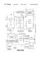
- FIG. 1is a schematic view of a residence which features one embodiment of a system according to the present invention.
- FIG. 2is a schematic, greatly simplified, representation of a Time Division Multiplex Access (“TDMA”) frame having eight slots supporting four bi-directional channels in accordance with one embodiment of the present invention.
- TDMATime Division Multiplex Access
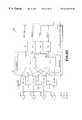
- FIG. 3Ais a high level functional block diagram of a Network Control Unit according to one embodiment of the present invention.
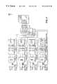
- FIG. 3Bis a schematic diagram, at a lower level than FIG. 3A, of a Network Control Unit according to one embodiment of the present invention in which four coder/decoder or “codec's” are employed in connection with four analog POTS lines.
- FIG. 3Cis a functional block diagram of a single codec which may accommodate the four lines, for instance, shown in FIG. 3B as an alternative design for purely analog POTS lines.
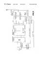
- FIG. 3Dis a high level functional block diagram of a Network Control Unit according to one embodiment of the present invention which is adapted to monitor, collect and report information about spectrum usage and status of wireless devices.
- FIG. 4is a functional block diagram of one embodiment of a handset according to the present invention.
- FIG. 5is a functional block diagram of one embodiment of a Wireless Access Unit according to the present invention.
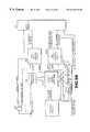
- FIG. 6is a functional block diagram of a Network Control Unit which is adapted to accommodate the ISDN standard, alone or in connection with other analog PSTN connections.
- FIG. 7is a functional block diagram of a Network Control Unit according to the present invention adapted to accommodate three analog and one digital PSTN connections.
- FIG. 8is a functional block diagram of one embodiment of a digital Wireless Access Unit according to the present invention.
- FIGS. 9A and 9Bare functional block diagrams as one embodiment of switching/processing circuitry contained in one embodiment of a Wireless Access Unit or handset according to the present invention.
- FIG. 10is a high level functional block diagram of transceiver circuitry which may be employed in the present invention if desired.
- FIG. 11Ais a simplified flow diagram illustrating one configuration sequence of the Network Control Unit of FIG. 3 .
- FIG. 11Bis a table showing configuration of the Network Control Unit of FIG. 3 resulting from the configuration sequence shown in FIG. 11 A.
- FIG. 12is a schematic diagram showing operation of a communications web according to the present invention according to Example 1 discussed below.
- FIG. 13is a schematic diagram showing operation of another communications web according to the present invention according to Example 2 discussed below.
- FIG. 1is a schematic hypothetical floor plan for a residence or business containing a communications web according to the present invention.
- the floor planshows a Network Control Unit or “NCU” 100 which terminates four central office POTS lines designated “C01” through “C04.”
- a number of Wireless Access Units or wireless jacks (“WAU's”) 201 - 203may be found throughout the floor plan, linked via RF link to the NCU.
- WAU'sWireless Access Units or wireless jacks
- a number of handsets and conventional telephones 300 - 304 whether portable or connected to a WAUmay also be found throughout the floor plan.
- Other electronic devicessuch as a fax 400 may be included; fax 400 in FIG. 1 is shown connected to a WAU 202 .
- PSTN lines or connectionsmay terminate in one or more NCUs for a particular location according to the present invention.
- the PSTN linesmay be analog or digital, and may incorporate any desired present or future analog or digital standard, format or protocol.
- WAUs according to the present inventionwhich may be RF linked to one or more NCUs for a particular location, can be adapted to accommodate any telecommunication, consumer electronic or other required standard, format or protocol, whether analog or digital and can be manufactured and sold individually for that purpose to render communications webs according to the present invention modular in nature with a mix of components to suit every reasonable taste and preference.
- a WAUmay connect to, for instance, a “telephone”, such as telephone instrument 300 in FIG.
- FIG. 1is purely a simple hypothetical floor plan in order to provide a modicum of perspective relative to NCUs, WAUs, handsets and other electronic devices as employed in communications webs of the present invention.
- FIGS. 3A through 3Cshow, in functional block diagram format, embodiments and portions of embodiments of Network Control Units (“NCU's”) according to the present invention.
- NCU 100includes interface circuitry for interfacing with PSTN lines or connections from a switch or other component of the PSTN, whether analog or digital.
- This circuitrydenominated “Network Interface” 650 as shown in FIG. A, couples to switching, bridging and accessory circuitry as shown with numeral 660 in FIG. 3 A.
- This discussionconsiders signals in a “downstream” or a PSTN to NCU to WAU direction, from which corresponding signal flow in the opposite direction is apparent.
- the Cross Connect Switch/Conference Bridge/Accessory Block (“CAB”) componentscouple signals from the Network Interface corresponding to incoming lines, in a predetermined and programmable manner, with additional functionality, if desired, to downstream circuitry for eventual RF transmission to WAU's and handsets.
- the switching and bridging components of the CABare the portion of the Network Control Unit that allow the subscriber either remotely or locally to designate by programming into the NCU which of his or her telephone instruments, computers, fax machines, and other devices connect to various PSTN lines at particular times of day or under particular conditions.
- the signals being properly switched and routed in the CAB as designated for the subscriber's devicesare then delivered to the NCU's “Radio Multiplex Engine” as shown in FIG. 3A with numeral 670 .
- the RMEmultiplexes the signals as, for instance, by time division multiplex access, or according to any desired format, onto a number of predetermined channels for bandwidth and RF frequency conservation.
- the multiplexed signalsare delivered to Radio Transceiver 680 where the signals may be conditioned, again multiplexed according to any desired format, and modulated onto an appropriate RF carrier or carriers in a programmable manner or as otherwise desired for transmission to WAUs 200 , handsets 300 and other devices if desired.
- An NCU Controller 690connects to all circuits in the NCU and may be programmed via user interface on the NCU, via computer coupled to the Controller or other portions of the NCU, or remotely over one of the incoming lines 640 .
- the Network Interface 650 of the NCUmay be modular in design and contains the circuits that connect to the public switched telephone network for accommodating various media, including twisted pair, coax, fiber and wireless, and various modes, including analog, digital or a hybrid.
- a Network Interfacemay be modular and portions for all lines may be implemented in applications specific integrated circuitry (“ASIC”) medium to accommodate analog circuits, or services requiring, among other interfaces, ISDN, T-1, CATV/COAX, ATM, micro-ATM, AMPS, N-AMPS, TDMA digital cellular, CDMA digital cellular, analog or digital SMR (Nextel), PCS, LEO satellite, geosychronous satellite, Internet protocol or any other present or future form of wireless or wireline local loop or other PSTN service.
- ASICapplications specific integrated circuitry
- the Network Interface for a systemwhich accommodates four POTS lines, could take the form of a quad arrangement of independent Direct Access Arrangement (“DAA”) circuits 690 , each having appropriate transformer, isolator and line protection circuitry as required, a two to four wire hybrid 700 , and a coder/decoder (“codec”) 10 .
- the Network Interface circuitryis accordingly adapted for appropriate isolation, impedance matching, line protection, medium conversion (two wire to four wire) and analog-to-digital/digital-to-analog conversion in order for its output signal 720 to be coupled to CAB 660 .
- the functionality in POTS versions of direct access arrangement circuits 690comprises conventional components and is conventionally implemented.
- FIG. 3Cshows an alternative arrangement for a Network Interface adapted to accommodate four POTS lines.
- the line conditioning circuitrywhich can include hybrids 700 and other components cross-couples to a single codec 710 , instead of the requirement that a codec be employed for each line 640 .
- Output of the Network Interfacemay be on a bus 730 instead of individual outputs coupled to CAB 660 , in order to couple Network Interface 650 to CAB 660 via a multiplexed connection for physical simplicity and logical implementation.
- the Network Interfacemay be the so-called “U-Interface” and associated 4 level dibit modem circuitry.
- Other digital servicesrequire a Network Interface especially adapted to interface to a particular medium, format and protocol.
- the Network Interfacemay be a wireless modem which includes a radio receiver or transceivers and appropriate modulation/demodulation, coding and decoding circuitry.
- the Network Interfaceis a wireless modem/Radio Transceiver
- the NCU 100operates as a radio transponder or rebroadcast unit, communicating with the PSTN via one wireless protocol, and with the WAUs 200 , handsets 300 and other components of systems according to the present invention via the same or perhaps different protocols.
- This aspect of the inventionmay be counter-intuitive: If the connection to the PSTN is wireless, one approach is simply to connect directly to any location in the residence instead of relaying signals through the NCU 100 .
- Radio Transceivers that interface to the PSTNtypically must comply with elaborate air interface standards having precise frequency control, well-defined RF bandwidth, higher transmit power (to accommodate the greater distance to a cell tower or PCS antenna), better receiver sensitivity, higher battery drain and shorter battery life, and increase complexity and expense.
- a handset 300 or a WAU 200 according to the present inventionis a far simpler and less expensive device which need only accommodate the present invention's less stringent internal air interface standards, but nevertheless retain the functionality to provide corded quality and reliability for indoor/nearby outdoor service that is inexpensive, compact, lightweight, flexible and manufactured and sold, if desired, tailored to specific devices such as faxes or various digital standards which not every subscriber may wish to employ.
- Incoming connections to the Network Interface 650could be physically separate twisted pairs as in the case of analog POTS lines where each line terminates from the PSTN via an independent twisted pair; alternatively, each incoming circuit can be multiplexed over a single pair, such as two digital circuits provided by a conventional, basic rate (2B+D) ISDN line.
- a 6 megabit per second micro-ATM fiber connectioncould provide digital voice service, MPEG video and other services over a single optical fiber which could be de-multiplexed (multiplexed for outgoing or upstream information) in the Network Interface, and incoming lines could be virtual. That is, additional lines could be assigned on an as needed basis and charged accordingly. For example, a subscriber might have connection to one line from 10:00 p.m.
- the CAB 660can be programmed to accommodate changes in the PSTN connections in real time in order to distribute bandwidth and service as desired among various WAUs 200 , handsets 300 and the other end user interface devices.
- Cross connect switch/conference bridge/accessory blocksmay be, electronically or virtually, an n ⁇ m switch which is programmed to interconnect any incoming signal 720 from the Network Interface 650 , (whether physical, virtual, multiplexed or wireless) to a number of output signals or interfaces which correspond to communications channels, according to one topology, or to combinations of the handsets, telephones, fax machines, computers or other devices serviced by WAU's 200 and/or handsets 300 of the present invention, according to another topology.
- the CAB 660can, but need not, include functionality simply to bridge or conference these same circuits and/or remote devices, thus eliminating the need for further processing of the signals beyond CAB 660 .
- a CABmay additionally contain a variety of decoders, generators, synthesizers and other circuits as desired.
- CAB 660is preferably coupled to a local Control Processor and/or an external computer and/or network or server, if desired.
- the external connectionmay be directly by bus or synchronous connection, or via any of the PSTN lines 640 .
- Control Processors 690 and other componentsmay be coupled and/or networked among various NCUs and/or external/or server control capacity.
- the CAB shown in FIG. 3Ais under control of a local Control Processor 685 and personal computer 687 .
- the CAB 660may function similar to a central switchboard and conference bridge routing each line to one or more Wireless Access Units 200 and/or handsets 300 as programmed in Control Processors 685 and/or PC 687 .
- Multiple lines 640 , handsets 300 , telephones connected to WAUs 200 , and other devicesmay be conferenced to form any number of permutations and combinations of conferences.
- One wireless handsetcan call another without using any of external lines 640 simply using the allotted time slots, codes or RF channels involving the two handsets 300 , or telephones connected to a WAU 200 .
- a conference call of any two or more internal handset or telephone devicescan similarly occur. Calls or conferences among multiple devices on multiple networked or shared NCU's can similarly occur.
- the CAB 660can be implemented in analog circuits including relays, transistors, CMOS media or any other application specific or nonspecific analog components and/or integrated circuits, but preferably signals 720 arriving at CAB 660 are digital so that CAB 660 may be implemented entirely digitally.
- CABs 660are adapted to route and direct data signals, such as, for example, when using external data services via Internet or internal networks within the subscriber's location.
- virtual circuitsmay be established for each call which can remain in place for the duration of a call.
- CSMACarrier Since Multiple Access
- packet switching protocolcan be employed, among other formats or protocols, in order to support a larger number of bursty devices.
- a combination of virtual data circuits and CSMAcan be employed if desired.
- CABs 660are also adapted to accommodate voice and data traffic simultaneously, routing traffic and managing resources as desired.
- Conference Bridge functionality in the CAB 660is preferably implemented as a high quality digital bridge which maintains all connections at suitable and equal audio levels.
- the Conference Bridge functionalitycan be implemented in analog circuits, again it is preferably implemented digitally using logic or digital signal processing. Digital leveling and noise control may be used to maintain voice circuit quality regardless of the numbers of parties bridged together.
- the Conference Bridgemay also be adapted to bridge in one or more outside lines onto an existing circuit, adding handsets 300 and/or WAUs 200 to the circuit.
- the Accessory Block functionalitymay contain features which add flexibility and additional levels of services to communications webs according to the present invention.
- the Accessory Block functionalitymay include, for instance, DTMF generator, DTMF decoder, speech synthesizer, speech recognizer, caller ID decoder, low or high speed telephone modem, fax modem capable of group III or similar functions, real time clock/calendar and other functionality as desired. These functions are provided in conjunction with the Control Processor 685 and other portions of CAB 660 to implement capability such as autodialing, remote programmability, voice command features, digital voice prompting, and other advanced functionality. Portions or all of the Accessory Block Functionality may be sited on board or remote to NCU 100 as desired for particular implementations.
- the NCU Switching, Bridging and Accessory Block functionality or any other software employed by NCU 100may reside on board the NCU and may but not be remotely programmable or upgradeable. It may also incorporate remotely accessed or pushed program and or data objects and/or applications as desired, including in the JAVA, Active/X, or other languages.
- NCU's 100preferably include a standard connector such as an RJ-11 connector which may be hardwired to a single line telephone or connected, for example, to existing in-home wiring.
- This connectorpermits the NCU 100 to manage the existing telephone or wiring as part of its network, perhaps permitting them to answer any ringing line.
- a POTS NCU 100could have a drop out relay or FET circuit which may automatically switch the existing wiring over to this connector in the event of a power failure or a system failure. If the NCU 100 is equipped with backup batteries or other auxiliary power, it may continue to function either until mains power is restored or its batteries become exhausted in which case it drops off-line and switches to the emergency bypass routing to the external connector.
- Control Processor 685commands switching, routing, RF, accessory and other functionality implemented in CAB 660 , Radio Transceiver 680 and other circuits in NCU 100 s according to the present invention.
- Control Processor 685could be a small micro-controller set, although more processing power may be required to accommodate ISDN and other digital interface NCUs 100 .
- external PCS 687 and, if desired, serversmay participate in the control functions.
- a very simple algorithm by which the Control Processor 685 governs CAB 660 for the topology shown in FIG. 1is shown in FIGS. 11A and 11B, in which, step-by-step, lines 640 are matched in the CAB 660 to various WAUs 200 , handsets 300 , and other devices.
- the control algorithms and programming itselfmay occur locally as by an interface 689 which may be implemented in buttons or a keyboard, by PC 687 or external connection, including network or PSTN.
- systems of the present inventionare adapted to permit control of the NCU 100 , including Control Processor 685 and CAB 660 from a remote service center so that a subscriber can call the service center in the event the subscriber feels technically short of the task of programming his or her NCU to accommodate various WAUs 200 and handsets 300 .
- PC and other external connectivityleverages on higher intelligence of the PC, additional mass memory functionality for updates and databases and similar applications, the more convenient user interface, and more elaborate applications software such as, for instance, directory management, spreadsheets and database managers.
- CAB output signals 750are coupled to a radio multiplex engine 670 according to the present invention which can comprise a digital logic block that implements any of the following functionality: multiplexing/demultiplexing, preferably but not necessarily TDMA/TDD (Time Division Multiplex Access/Time Division Duplex), forward error control and general error management, speech compression if required, code division multiplex and demultiplexing, if any, hopset generation if any, and other critical timing, synchronization and coding functions critical to the operation of the systems according to the present invention.
- TDMA/TDDTime Division Multiplex Access/Time Division Duplex
- forward error control and general error managementspeech compression if required
- code division multiplex and demultiplexingif any, hopset generation if any, and other critical timing, synchronization and coding functions critical to the operation of the systems according to the present invention.
- RME's 670generally but not necessarily operate at speeds sufficiently high to render Control Processor 685 management ineffective, although that need not be the case.
- RME signals 770are coupled, in systems of the present invention, to wireless Radio Transceiver (“RT”) circuitry 680 as shown in FIG. 3 A.
- the RT 680may be a low cost multiplexed Radio Transceiver or set of transceivers which provides proper modulation onto RF carriers as desired with or without multiplexing and duplexing according to any of the following formats or others: TDMA/TDD, TDMA/FDD, CDMA/FDD, CDMA/TDD, FHMA/TDD, or FHMA/FDD.
- the primary functionis to achieve transmission of multiple simultaneous independent data streams to WAUs 200 and handsets 300 .
- the RT circuitry 680need not conform to any error interface standard, since it communicates only with like equipment and usually does not interface to the PSTN or any other public network except via a separate, higher quality transceiver if any is implemented in the Network Interface 650 or connected to it.
- the RT unit 680can communicate with other NCUs 100 that fall within radio range.
- the NCUs 100can share hopset data interference records, timing and usage information, all toward the end of avoiding one another's transmissions.
- the components of each system, NCUs 100 , WAUs 200 , handsets 300all transmit at the lowest power possible to provide reliable communications, using power management sensing and response to the circuits. In this manner, each system minimizes its “radius of interference,” the approximate circular area surrounding a given system within which it is capable of generating interference in other systems operating in the same band.
- the NCU 100 and/or the peripheral or wireless units or devicescan activate themselves and monitor frequencies which may be the same as or other than the principal one which is currently in use. Whether or not they do so on a continual basis, a data log of spectral occupancy may be created and stored in a virtual table. For instance, a histogram of usage statistics on an hourly basis for each available channel can be used.
- FIG. 3 DAn NCU capable of spectrum monitoring according to the present invention is shown in FIG. 3 D.
- processor circuitry 685 or any other desired control circuitrycontrols operation of the receiver portion of the Radio Multiplex Engine 670 .
- Signals from the RME 670may be processed in processing circuitry 685 (or any other processing capacity) and information relating to bands of interests and signals and noise therein may be collected and/or stored in storage 850 or any other desired storage capacity of whatever medium desired. Such information may be reported to the management node 860 via Network Interface 650 or as otherwise desired.
- Spectrum monitoring according to the present inventioncan be implemented and employed not only in systems with such NCU's, however; it may also be implemented in and occur in conventional cordless telephones and other wireless devices.
- devices according to the present inventioncan quite readily discern both frequency and bandwidth by sweeping the receiver's local oscillator (frequency synthesizer) in frequency steps much smaller than the receiver bandwidth. For instance, an unmodulated carrier could be discerned by sweeping the receiver in small increments and averaging the frequencies where equal power is measured in the receiver. Likewise, scanning could be performed using one up sweep and one down sweep, noting frequencies and associated received signal strengths. Scanning is not necessary, however, and bands of interest could be monitored in gross.
- NCU 100 or wireless device associated with itwere on the air within receiver range, its signal can be demodulated, and an annotation can appear in the virtual table of this frequency and location.
- the systemmay also sweep or otherwise monitor spectrum beyond the outer band edges so as to gain an accurate measurement of signal characteristics for signals close to operating band edges or for other purposes.
- Information corresponding to signals and noise in the monitored bandscan be used to adjust operation of apparatus according to the present invention (by adjusting timing, frequency or other operation), and/or if desired may be sent upstream to a node on the telecommunications network such as, for instance, a management node 860 , to provide detailed reports of the availability and spectral occupancy within the bands of interest for the purpose of monitoring local bandwidth congestion, and the general utilization of the system with respect to voice and data services.
- a node on the telecommunications networksuch as, for instance, a management node 860
- a large number of these localized, spot measurements collected at various peak and off-peak telephone usage hours, amassed and integrated in one database,can collectively form the most current, accurate national bandwidth survey conceivable.
- a usage archive according to the present inventioncould document actual usage and allow observation of trends in order, for example, to predict changes in PSTN subscribers needs, which in turn would allow adaptation of products and systems more rapidly to address changing needs and avoid premature obsolescence.
- an NCU 100detect another NCU 100 or associated WAU, handset or other wireless device operating within range of it, information can be collected and acted upon including, for instance, the type of peripheral unit in operation, such as a wireless handset, a DB-9 wireless jack, or an RJ-11 wireless jack, times of operation, signal strength, and operating frequencies. Other signals may also be included as part of such information.
- This informationcan serve to tailor operation of either or both NCU's and associated devices to the subscribers' individual needs by among other things adjusting operation to avoiding the frequencies or times optimally favored by other systems, for purposes of increasing the system's reliability and clarity.
- the NCU 100may signal the user via output on a WAU, handset or other associated device, or simply adjust operation to avoid such conflicting signals or noise. Warnings could include a flashing LED, audible tone warning, or other alert that the system had encountered broadband interference.
- Computers, printers, fax machines and other modern-day office appliancesuse microprocessors and digital signal processing to perform their tasks. The high-speed logic and high clock speeds used in these accessories lead to the generation of significant amounts of broadband RF noise, often to frequencies of 1 GHz and beyond.
- the user's manual for systems according to the present inventioncould inform the user, for instance, that, “If the green LED on the wireless jack is flashing, the unit may be located in an area of high interference. Please move the unit to an AC outlet that is further away from your computer equipment.” The time, strength, and duration of the noise interference could be archived for later analysis by online service technicians.
- Archiving according to the present inventioncan also store useful system-maintenance and troubleshooting data. For instance, when a call is terminated, it could examine and store the following parameters:
- the systemcan build an effective service archive, a record that can be examined in the event of repeated system malfunction.
- This archivecan be uploaded to the node for examination by a service technician.
- the archivecan also monitor telephone line status. If a certain line were experiencing noise, hum or periodic outage, the system could record line voltage over a period of time, reporting this information to the node, which could in turn report it to the telephone operating company.
- Wireless Access Units 200may be of two general sorts: (1) analog for a wireless telephone jack function such as one that can accommodate a telephone or a conventional modem; or (2) digital, for a wireless computer or digital device connection (such as DB-25, USB, Ethernet, ISDN-ST, PCMCIA or similar serial or parallel data communications connection).
- analog for a wireless telephone jack functionsuch as one that can accommodate a telephone or a conventional modem
- digital, for a wireless computer or digital device connectionsuch as DB-25, USB, Ethernet, ISDN-ST, PCMCIA or similar serial or parallel data communications connection.
- FIG. 5shows one form of analog WAU 200 according to the present invention.
- the analog WAU 200may include a Radio Transceiver 800 which links WAU 200 via RF connection to NCU 100 , a Radio Multiplex Engine 802 , a Control Processor 804 , and circuitry that provides basic subscriber loop functions of battery, over voltage protection, ringing, supervision (off hook sensing), codec, hybrid and test functionality (so called borscht) functionality.
- the unit 5may be implemented in a small unit which resembles a wall transformer with one or more RJ-11 jacks on the back or side, and it can, if desired, draw power from any AC outlet and provide an analog telephone type connection to a computer modem, a fax machine, a telephone answering device, a standard telephone or any other device that connects with a standard RJ-11 jack.
- the unitis transparent to caller ID information, and passes it through. Similarly, the unit passes through coded ringing and other custom signaling. Its power supply provides power for standard telephones which are line powered. Its high voltage ring generator rings telephones with the standard 60 volt rms., 20-Hz ring signal.
- this unitis typically though not necessarily “wired” to the AC power wiring and therefore is not totally “wireless,” the length between this unit and the incoming lines 640 connected to NCU 100 is wireless. It therefore eliminates the subscriber's need to place telephones where telephone outlets are located. Battery power, if employed, provides even more flexibility in location.
- a digital Wireless Access Unit 200 of one sort according to the present inventionis shown in FIG. 6 .
- Such a Wireless Access Unit 200can provide wireless connection to computers, computer peripherals, ISDN-ST telephone sets and other digital devices. Since the radio link used in systems according to the present invention is digital, the digital circuitry in the Wireless Access Unit 200 principally performs a buffering, error control, and protocol conversion function.
- the external digital interfacecan take many forms, including DB-25, the standard serial port connector; USB, Intel's new universal serial bus standard; parallel-port (printer) connection; Ethernet; 10-base-T; 100-base-T, Fast or Gigabit Ethernet; PCMCIA and others.
- Digital Wireless Access Unit 200like analog Wireless Access Unit 200 , may be mains or battery powered, so that they may provide untethered convenience to the user.
- Systems according to the present inventioncan also perform many control and monitoring functions at a subscriber's location for convenience and increased efficiency.
- a wireless doorbell accessory or WAU 200can emit a coded ring in response to a ringing doorbell signal. The subscriber could then press an “intercom” soft key, placing the subscriber in full duplex communications with the front door visitor and possibly calling up his or her image on a display.
- Other wireless accessoriescan provide control over home lighting, garage door opening, and security monitoring.
- the handset or other interface devicecan control televisions, stereo equipment, heating, air conditioning and appliances. Baby monitoring via wireless audio monitor and other consumer electronics functionality are accommodated by the present system, whether or not via the CE-bus.
- the four main component parts of systems of the present inventionare the Network Control Unit 100 , Wireless Access Units 200 , handsets 300 and Wireless Control/Monitoring Accessories 350 . While each component may contain an onboard microcontroller which governs its basic functions, the NCU 100 alone or acting in concert with external controller capacity is preferably the principal controller and manager of the entire communications web. All remote components are preferably simple, reliable and preferably of limited intelligence/functionality for reduced costs and increased modularity and so that system performance and functions are principally determined by the NCU 100 .
- the NCU 100may contain on-line firmware and/or software upgrade capability as discussed above.
- the NCU 100is the central part of the systems' star network topology. for the entire system, the NCU 100 selects RF channels, hop sequences if any, and spreading codes if any; it managers ID strings for the various remotes, and it performs the other functions related to network management, remote unit registration and authentication, and communications protocol management.
- the NCU 100also controls the switching and interconnection of the CAB 660 , and drives all the Accessory Block features of CAB 660 .
- the following examplesdescribe operation of two embodiments of the communications webs according to the present invention.
- a system according to the present inventionis shown in FIG. 12 with four incoming POTS lines, an NCU 100 in the basement or attic, a wireless handset, and three Wireless Access Units 200 which correspond to a telephone, a computer, and a fax machine.
- the systemmay be programmed as follows: POTS line 1 is programmed in the CAB 660 to ring through and connect to the LCD handset 300 . POTS line 2 rings through and connects to Wireless Access Unit number 1 which is connected to a standard telephone via an RJ-11 jack. POTS line 3 connects to Wireless Access Unit number 2 , which is, in turn, adapted to accommodate a fax machine. POTS line 4 connects to Wireless Access Unit number 3 which connects via RS-232 interface to a personal computer.
- Signals from POTS lines 1 - 4are coupled to Radio Multiplex Engine 670 , multiplexed as in TDMA format and modulated onto an RF carrier in RT or digital radio modem 680 for transmission.
- Handset 300receives the signal from the NCU 100 , and demodulates, demultiplexes and processes the information intended for handset 300 . That information is contained in a signal provided to the interfacing circuitry and coder/decoder 650 for delivery to the human interface. The signals are also provided to an LCD driver and screen. In an upstream direction, signals from the keypad and microphone are processed, multiplexed, modulated and forwarded to NCU 100 which ultimately demodulates, demultiplexes and processes the signals for delivery to POTS line 1 .
- Wireless Access Units 1 - 3operate generally in a similar manner as far as the RF and multiplexing circuitry are concerned.
- Wireless Access Unit number Icontains interface circuitry adapted to accommodate a standard telephone, including, for example, coder/decoder circuitry, line interface, battery, supervision, and ring generator circuitry which interfaces to an RF-11 jack.
- Wireless Access Unit number 2 interface circuitry intended for a fax machinemay be similar or identical to Wireless Access Unit number 1 .
- Wireless Access Unit number 3is configured with interface circuitry to accommodate a RS-232 port rather than an RF-11 analog jack. Accordingly, forward error correction, universal asynchronous receiver/transmitter and handshaking circuitry is included in connection with RS-232 serial port standards.
- POTS line 3could be reprogrammed in the CAB 660 to accommodate Wireless Access Unit number 3 for computer communications while POTS line 2 is configured to ring through to Wireless Access Units 1 and 2 for the telephone and fax machine. Any other combination may be employed as desired, as the user desires new services or different services, or adds devices to the communications web with their attendant Wireless Access Units.
- FIG. 13Another system according to the present invention is shown in FIG. 13 with two incoming POTS lines and an ISDN line.
- POTS line 1is programmed in CAB 660 of Network Control Unit 100 to ring through and connect to LCD handset 300 .
- POTS line 2is programmed to ring through and connect to Wireless Access Unit number 1 and number 2 , which in turn connect to the standard telephone and a fax machine, respectively.
- the ISDN lineis programmed to connect to Wireless Access Unit number 3 and thus to a computer via a serial port.
- the linesmay be programmed to connect to various handsets 300 and Wireless Access Units 200 as desired as the user desires new or additional services or adds other devices. With the existing devices shown in FIG.
- the usercould program CAB 660 to connect POTS line 1 to handset 300 and Wireless Access Units 1 and 2 in order to eliminate the second POTS line.
- line 1could be designated the voice line for connection to handset 300 and Wireless Access Unit number 1 .
- Line 1 or Line 2could also be wired in the Network Interface 650 or otherwise to connect directly through to existing wiring as shown in FIG. 13 .
Landscapes
- Engineering & Computer Science (AREA)
- Computer Networks & Wireless Communication (AREA)
- Signal Processing (AREA)
- Mobile Radio Communication Systems (AREA)
- Monitoring And Testing Of Exchanges (AREA)
- Use Of Switch Circuits For Exchanges And Methods Of Control Of Multiplex Exchanges (AREA)
- Telephonic Communication Services (AREA)
Abstract
Description
Claims (39)
Priority Applications (11)
| Application Number | Priority Date | Filing Date | Title |
|---|---|---|---|
| US09/083,464US6418131B1 (en) | 1994-06-17 | 1998-05-22 | Spectrum monitoring for PSTN subscribers |
| RU2000132201/09ARU2000132201A (en) | 1998-05-22 | 1999-05-19 | CONTROL OF THE SPECTRUM FOR SUBSCRIBERS OF THE SWITCHED TELEPHONE NETWORK OF GENERAL USE |
| KR1020007013160AKR20010043771A (en) | 1998-05-22 | 1999-05-19 | Spectrum monitoring for pstn subscribers |
| BR9910663-9ABR9910663A (en) | 1998-05-22 | 1999-05-19 | Spectrum monitoring for pstn subscribers |
| PCT/US1999/011079WO1999062290A1 (en) | 1998-05-22 | 1999-05-19 | Spectrum monitoring for pstn subscribers |
| AU41923/99AAU4192399A (en) | 1998-05-22 | 1999-05-19 | Spectrum monitoring for pstn subscribers |
| EP99925685AEP1080602A1 (en) | 1998-05-22 | 1999-05-19 | Spectrum monitoring for pstn subscribers |
| JP2000551572AJP2002517147A (en) | 1998-05-22 | 1999-05-19 | Spectrum monitoring for PSTN subscribers |
| CA002330375ACA2330375A1 (en) | 1998-05-22 | 1999-05-19 | Spectrum monitoring for pstn subscribers |
| MXPA00011486AMXPA00011486A (en) | 1998-05-22 | 1999-05-19 | Spectrum monitoring for pstn subscribers. |
| ARP990102401AAR014075A1 (en) | 1998-05-22 | 1999-05-20 | APPARATUS TO ALLOW A SUBSCRIBER TO COMMUNICATE THROUGH AN EXTERNAL TELECOMMUNICATIONS NETWORK WITH OTHER NODES IN THE EXTERNAL TELECOMMUNICATIONS NETWORK. SYSTEM FOR COMMUNICATION THROUGH A TELECOMMUNICATIONS NETWORK |
Applications Claiming Priority (4)
| Application Number | Priority Date | Filing Date | Title |
|---|---|---|---|
| US08/262,214US5555258A (en) | 1994-06-17 | 1994-06-17 | Home personal communication system |
| US08709597US5805582B1 (en) | 1994-06-17 | 1996-09-09 | Home personal communications system |
| US08/843,700US6058104A (en) | 1994-06-17 | 1997-04-16 | Communications webs for PSTN subscribers |
| US09/083,464US6418131B1 (en) | 1994-06-17 | 1998-05-22 | Spectrum monitoring for PSTN subscribers |
Related Parent Applications (1)
| Application Number | Title | Priority Date | Filing Date |
|---|---|---|---|
| US08/843,700Continuation-In-PartUS6058104A (en) | 1994-06-17 | 1997-04-16 | Communications webs for PSTN subscribers |
Publications (1)
| Publication Number | Publication Date |
|---|---|
| US6418131B1true US6418131B1 (en) | 2002-07-09 |
Family
ID=22178525
Family Applications (1)
| Application Number | Title | Priority Date | Filing Date |
|---|---|---|---|
| US09/083,464Expired - LifetimeUS6418131B1 (en) | 1994-06-17 | 1998-05-22 | Spectrum monitoring for PSTN subscribers |
Country Status (11)
| Country | Link |
|---|---|
| US (1) | US6418131B1 (en) |
| EP (1) | EP1080602A1 (en) |
| JP (1) | JP2002517147A (en) |
| KR (1) | KR20010043771A (en) |
| AR (1) | AR014075A1 (en) |
| AU (1) | AU4192399A (en) |
| BR (1) | BR9910663A (en) |
| CA (1) | CA2330375A1 (en) |
| MX (1) | MXPA00011486A (en) |
| RU (1) | RU2000132201A (en) |
| WO (1) | WO1999062290A1 (en) |
Cited By (45)
| Publication number | Priority date | Publication date | Assignee | Title |
|---|---|---|---|---|
| US20020061729A1 (en)* | 2000-11-18 | 2002-05-23 | Zhang Franklin Zhigang | Fixed wireless network extender |
| US20020110151A1 (en)* | 2000-08-21 | 2002-08-15 | Dickey Sergey L. | Method and apparatus for CDMA pn scanning at indoor and other obstructed locations |
| US6574769B1 (en)* | 1997-12-12 | 2003-06-03 | Thomson Licensing Sa | Enhanced range/graceful degradation for digital wireless telephone system |
| US20030169752A1 (en)* | 2000-01-31 | 2003-09-11 | Aeptec Microsystems, Inc. | Broadband communications access device |
| US20030198200A1 (en)* | 2002-04-22 | 2003-10-23 | Cognio, Inc. | System and Method for Spectrum Management of a Shared Frequency Band |
| US20030200462A1 (en)* | 1999-05-11 | 2003-10-23 | Software Systems International Llc | Method and system for establishing normal software system behavior and departures from normal behavior |
| US20040028003A1 (en)* | 2002-04-22 | 2004-02-12 | Diener Neil R. | System and method for management of a shared frequency band |
| US20040047324A1 (en)* | 2002-09-11 | 2004-03-11 | Diener Neil R. | System and method for management of a shared frequency band using client--specific management techniques |
| US20040137915A1 (en)* | 2002-11-27 | 2004-07-15 | Diener Neil R. | Server and multiple sensor system for monitoring activity in a shared radio frequency band |
| US20040151205A1 (en)* | 2003-01-30 | 2004-08-05 | Young-Hyun Kang | Method for batch registration of integrated digital loop carrier subscriber using program loaded data of exchange, and element management system server for the same |
| US6792268B1 (en)* | 2001-09-07 | 2004-09-14 | At&T Corporation | Method for uplink spectrum monitoring for sparse overlay TDMA systems |
| US20050068906A1 (en)* | 2003-09-30 | 2005-03-31 | Muri David L. | Method and system for group communications in a wireless communications system |
| US20050073983A1 (en)* | 2003-10-03 | 2005-04-07 | Diener Neil R. | Automated real-time site survey in a shared frequency band environment |
| US20050213732A1 (en)* | 2001-12-31 | 2005-09-29 | Polycom, Inc. | Conference bridge which decodes and responds to control information embedded in audio information |
| US20050227625A1 (en)* | 2004-03-25 | 2005-10-13 | Diener Neil R | User interface and time-shifted presentation of data in a system that monitors activity in a shared radio frequency band |
| US7403795B1 (en)* | 2000-09-18 | 2008-07-22 | International Business Machines Corporation | Telephone network edge node device and method for bridging and privacy |
| US20090036159A1 (en)* | 2000-01-31 | 2009-02-05 | 3E Technologies International, Inc. | Broadband communications access device |
| US20100110910A1 (en)* | 2008-11-04 | 2010-05-06 | Broadcom Corporation | Multiservice communication device with dedicated environmental monitoring |
| USRE43308E1 (en)* | 1999-11-23 | 2012-04-10 | Auctnyc 7 Llc | Adjustment of period of real-time slow drift correction of alignment of handset's local oscillator for a cordless telephone |
| US8355502B1 (en)* | 2003-05-12 | 2013-01-15 | Xilinx, Inc. | Evolved circuits for bitstream protection |
| US8750156B1 (en) | 2013-03-15 | 2014-06-10 | DGS Global Systems, Inc. | Systems, methods, and devices for electronic spectrum management for identifying open space |
| US8780968B1 (en) | 2013-03-15 | 2014-07-15 | DGS Global Systems, Inc. | Systems, methods, and devices for electronic spectrum management |
| US8787836B1 (en) | 2013-03-15 | 2014-07-22 | DGS Global Systems, Inc. | Systems, methods, and devices having databases and automated reports for electronic spectrum management |
| US8798548B1 (en) | 2013-03-15 | 2014-08-05 | DGS Global Systems, Inc. | Systems, methods, and devices having databases for electronic spectrum management |
| US8805292B1 (en) | 2013-03-15 | 2014-08-12 | DGS Global Systems, Inc. | Systems, methods, and devices for electronic spectrum management for identifying signal-emitting devices |
| US10122479B2 (en) | 2017-01-23 | 2018-11-06 | DGS Global Systems, Inc. | Systems, methods, and devices for automatic signal detection with temporal feature extraction within a spectrum |
| US10219163B2 (en) | 2013-03-15 | 2019-02-26 | DGS Global Systems, Inc. | Systems, methods, and devices for electronic spectrum management |
| US10231206B2 (en) | 2013-03-15 | 2019-03-12 | DGS Global Systems, Inc. | Systems, methods, and devices for electronic spectrum management for identifying signal-emitting devices |
| US10237770B2 (en) | 2013-03-15 | 2019-03-19 | DGS Global Systems, Inc. | Systems, methods, and devices having databases and automated reports for electronic spectrum management |
| US10244504B2 (en) | 2013-03-15 | 2019-03-26 | DGS Global Systems, Inc. | Systems, methods, and devices for geolocation with deployable large scale arrays |
| US10257729B2 (en) | 2013-03-15 | 2019-04-09 | DGS Global Systems, Inc. | Systems, methods, and devices having databases for electronic spectrum management |
| US10257728B2 (en) | 2013-03-15 | 2019-04-09 | DGS Global Systems, Inc. | Systems, methods, and devices for electronic spectrum management |
| US10257727B2 (en) | 2013-03-15 | 2019-04-09 | DGS Global Systems, Inc. | Systems methods, and devices having databases and automated reports for electronic spectrum management |
| US10271233B2 (en) | 2013-03-15 | 2019-04-23 | DGS Global Systems, Inc. | Systems, methods, and devices for automatic signal detection with temporal feature extraction within a spectrum |
| US10299149B2 (en) | 2013-03-15 | 2019-05-21 | DGS Global Systems, Inc. | Systems, methods, and devices for electronic spectrum management |
| US10459020B2 (en) | 2017-01-23 | 2019-10-29 | DGS Global Systems, Inc. | Systems, methods, and devices for automatic signal detection based on power distribution by frequency over time within a spectrum |
| US10498951B2 (en) | 2017-01-23 | 2019-12-03 | Digital Global Systems, Inc. | Systems, methods, and devices for unmanned vehicle detection |
| US10529241B2 (en) | 2017-01-23 | 2020-01-07 | Digital Global Systems, Inc. | Unmanned vehicle recognition and threat management |
| US10644815B2 (en) | 2017-01-23 | 2020-05-05 | Digital Global Systems, Inc. | Systems, methods, and devices for automatic signal detection based on power distribution by frequency over time within an electromagnetic spectrum |
| US10943461B2 (en) | 2018-08-24 | 2021-03-09 | Digital Global Systems, Inc. | Systems, methods, and devices for automatic signal detection based on power distribution by frequency over time |
| US11646918B2 (en) | 2013-03-15 | 2023-05-09 | Digital Global Systems, Inc. | Systems, methods, and devices for electronic spectrum management for identifying open space |
| US12183213B1 (en) | 2017-01-23 | 2024-12-31 | Digital Global Systems, Inc. | Unmanned vehicle recognition and threat management |
| US12205477B2 (en) | 2017-01-23 | 2025-01-21 | Digital Global Systems, Inc. | Unmanned vehicle recognition and threat management |
| US12256233B2 (en) | 2013-03-15 | 2025-03-18 | Digital Global Systems, Inc. | Systems and methods for automated financial settlements for dynamic spectrum sharing |
| US12356206B2 (en) | 2013-03-15 | 2025-07-08 | Digital Global Systems, Inc. | Systems and methods for automated financial settlements for dynamic spectrum sharing |
Citations (58)
| Publication number | Priority date | Publication date | Assignee | Title |
|---|---|---|---|---|
| US3949172A (en) | 1974-02-08 | 1976-04-06 | Brown William M | Telephone extension system utilizing power line carrier signals |
| US4058678A (en) | 1976-04-07 | 1977-11-15 | Astech, Inc. | Remote signalling to a telephone line utilizing power line carrier signals |
| US4456793A (en) | 1982-06-09 | 1984-06-26 | Bell Telephone Laboratories, Incorporated | Cordless telephone system |
| US4475193A (en) | 1982-09-30 | 1984-10-02 | Astech, Inc. | Power line carrier multi telephone extension system for full duplex conferencing between telephones |
| US4479033A (en) | 1982-03-29 | 1984-10-23 | Astech, Inc. | Telephone extension system utilizing power line carrier signals |
| US4514594A (en) | 1982-09-30 | 1985-04-30 | Astech, Inc. | Power line carrier telephone extension system for full duplex conferencing between telephones and having telephone call hold capability |
| US4523307A (en) | 1982-11-30 | 1985-06-11 | Astech, Inc. | Power line carrier multi telephone extension system for full duplex conferencing and intercom between telephones |
| US4658096A (en) | 1984-09-18 | 1987-04-14 | Metrofone, Inc. | System for interfacing a standard telephone set with a radio transceiver |
| US4675863A (en) | 1985-03-20 | 1987-06-23 | International Mobile Machines Corp. | Subscriber RF telephone system for providing multiple speech and/or data signals simultaneously over either a single or a plurality of RF channels |
| US4737975A (en) | 1984-09-18 | 1988-04-12 | Metrofone, Inc. | Programmable system for interfacing a standard telephone set with a radio transceiver |
| US4776001A (en) | 1985-08-27 | 1988-10-04 | Nippon Telegraph And Telephone Corporation | Radio telephone system control apparatus and method |
| US4775997A (en) | 1984-09-18 | 1988-10-04 | Metrofone, Inc. | System for interfacing a standard telephone set with a radio transceiver |
| US4779262A (en) | 1986-10-21 | 1988-10-18 | International Mobile Machines Corp. | Connection of subscriber communication network base station to external information network |
| US4785450A (en) | 1987-08-06 | 1988-11-15 | International Mobile Machines Corporation | Apparatus and method for obtaining frequency agility in digital communication systems |
| US4792946A (en) | 1987-04-07 | 1988-12-20 | Spectrum Electronics, Inc. | Wireless local area network for use in neighborhoods |
| JPS6416051A (en) | 1987-07-10 | 1989-01-19 | Meisei Electric Co Ltd | Telephone set |
| JPS6457860A (en) | 1987-08-28 | 1989-03-06 | Omron Tateisi Electronics Co | Telephone system |
| US4825448A (en) | 1986-08-07 | 1989-04-25 | International Mobile Machines Corporation | Subscriber unit for wireless digital telephone system |
| JPH01309531A (en) | 1988-06-08 | 1989-12-13 | Toshiba Corp | Radio telephone system |
| JPH01309530A (en) | 1988-06-08 | 1989-12-13 | Victor Co Of Japan Ltd | Premises radio telephone system |
| JPH0234046A (en) | 1988-07-25 | 1990-02-05 | Toshiba Corp | wireless telephone system |
| JPH0234047A (en) | 1988-07-25 | 1990-02-05 | Toshiba Corp | wireless telephone equipment |
| JPH0263352A (en) | 1988-08-30 | 1990-03-02 | Aiphone Co Ltd | Cordless home telephone system |
| US4922517A (en) | 1987-04-08 | 1990-05-01 | Metrofone, Inc. | System for interfacing a standard telephone set with a radio transceiver |
| US5008900A (en) | 1989-08-14 | 1991-04-16 | International Mobile Machines Corporation | Subscriber unit for wireless digital subscriber communication system |
| JPH03179957A (en) | 1989-12-08 | 1991-08-05 | Sekisui Chem Co Ltd | Telephone system |
| US5072308A (en) | 1989-06-21 | 1991-12-10 | International Mobile Machines Corporation | Communication signal compression system and method |
| US5146473A (en) | 1989-08-14 | 1992-09-08 | International Mobile Machines Corporation | Subscriber unit for wireless digital subscriber communication system |
| US5168507A (en) | 1986-08-07 | 1992-12-01 | International Mobile Machines Corporation | Automatic adaptive equalizer |
| CA2053776A1 (en) | 1991-10-22 | 1993-04-23 | Rolf G. Meier | Cov wireless interface |
| US5212830A (en) | 1991-05-31 | 1993-05-18 | International Mobile Machines Corporation | Radio frequency communications system |
| JPH05153043A (en) | 1991-11-26 | 1993-06-18 | Matsushita Electric Ind Co Ltd | Wireless telephone |
| US5224120A (en) | 1990-12-05 | 1993-06-29 | Interdigital Technology Corporation | Dynamic capacity allocation CDMA spread spectrum communications |
| US5228056A (en) | 1990-12-14 | 1993-07-13 | Interdigital Technology Corporation | Synchronous spread-spectrum communications system and method |
| US5228053A (en) | 1991-05-15 | 1993-07-13 | Interdigital Technology Corporation | Spread spectrum cellular overlay CDMA communications system |
| US5260941A (en) | 1990-10-31 | 1993-11-09 | Rose Communications, Inc. | Digital radio telephone system |
| US5260967A (en) | 1992-01-13 | 1993-11-09 | Interdigital Technology Corporation | CDMA/TDMA spread-spectrum communications system and method |
| US5263045A (en) | 1990-12-05 | 1993-11-16 | Interdigital Technology Corporation | Spread spectrum conference call system and method |
| US5274665A (en) | 1990-12-14 | 1993-12-28 | Interdigital Technology Corporation | Polyopoly overlapping spread spectrum communication system and method |
| US5276703A (en) | 1992-01-13 | 1994-01-04 | Windata, Inc. | Wireless local area network communications system |
| US5289497A (en) | 1991-05-23 | 1994-02-22 | Interdigital Technology Corporation | Broadcast synchronized communication system |
| US5299226A (en) | 1990-11-16 | 1994-03-29 | Interdigital Technology Corporation | Adaptive power control for a spread spectrum communications system and method |
| US5307399A (en) | 1992-03-06 | 1994-04-26 | Glenayre Electronics, Inc. | Paging system that allows caller/subscriber interconnection |
| US5361294A (en) | 1992-12-23 | 1994-11-01 | Motorola, Inc. | Method and apparatus for noise quieting during resynchronization of a digital communication system |
| US5381446A (en) | 1993-06-25 | 1995-01-10 | Digital Wireless Corp. | Digital implementation of spread spectrum communications system |
| US5384826A (en) | 1990-10-01 | 1995-01-24 | At&T Bell Laboratories | Distributed packetized switching cellular radio telephone communication system with handoff |
| US5416778A (en) | 1992-06-26 | 1995-05-16 | U.S. Philips Corporation | Digital radio communication system and primary and secondary station for use in such a system |
| US5497373A (en) | 1994-03-22 | 1996-03-05 | Ericsson Messaging Systems Inc. | Multi-media interface |
| WO1996012264A2 (en) | 1994-10-13 | 1996-04-25 | Philips Electronics N.V. | A wireless object locating system and a central station and a radio alarm apparatus |
| US5533027A (en) | 1993-02-16 | 1996-07-02 | Telefonaktiebolaget Lm Ericsson | Digital fixed radio access system providing local mobility |
| US5555258A (en) | 1994-06-17 | 1996-09-10 | P. Stuckey McIntosh | Home personal communication system |
| US5610912A (en) | 1994-08-01 | 1997-03-11 | British Telecommunications Public Limited Company | Switching in a telecommunications service node |
| US5805582A (en) | 1994-06-17 | 1998-09-08 | Home Wireless Networks, Inc. | Home personal communications system |
| US5812951A (en)* | 1994-11-23 | 1998-09-22 | Hughes Electronics Corporation | Wireless personal communication system |
| WO1998049850A1 (en) | 1997-04-16 | 1998-11-05 | Home Wireless Networks, Inc. | Communications webs for pstn subscribers |
| EP0918423A2 (en) | 1997-10-15 | 1999-05-26 | Nokia Mobile Phones Ltd. | Mobile phone for Internet applications |
| US6052365A (en) | 1995-06-02 | 2000-04-18 | Dsc Communications Corporation | Multi-channel digital data transmission in a wireless telecommunications system |
| US6097733A (en) | 1997-06-13 | 2000-08-01 | Nortel Networks Corporation | System and associated method of operation for managing bandwidth in a wireless communication system supporting multimedia communications |
- 1998
- 1998-05-22USUS09/083,464patent/US6418131B1/ennot_activeExpired - Lifetime
- 1999
- 1999-05-19EPEP99925685Apatent/EP1080602A1/ennot_activeCeased
- 1999-05-19MXMXPA00011486Apatent/MXPA00011486A/ennot_activeApplication Discontinuation
- 1999-05-19WOPCT/US1999/011079patent/WO1999062290A1/ennot_activeApplication Discontinuation
- 1999-05-19JPJP2000551572Apatent/JP2002517147A/enactivePending
- 1999-05-19CACA002330375Apatent/CA2330375A1/ennot_activeAbandoned
- 1999-05-19AUAU41923/99Apatent/AU4192399A/ennot_activeAbandoned
- 1999-05-19KRKR1020007013160Apatent/KR20010043771A/ennot_activeWithdrawn
- 1999-05-19BRBR9910663-9Apatent/BR9910663A/ennot_activeApplication Discontinuation
- 1999-05-19RURU2000132201/09Apatent/RU2000132201A/ennot_activeApplication Discontinuation
- 1999-05-20ARARP990102401Apatent/AR014075A1/enunknown
Patent Citations (74)
| Publication number | Priority date | Publication date | Assignee | Title |
|---|---|---|---|---|
| US3949172A (en) | 1974-02-08 | 1976-04-06 | Brown William M | Telephone extension system utilizing power line carrier signals |
| US4058678A (en) | 1976-04-07 | 1977-11-15 | Astech, Inc. | Remote signalling to a telephone line utilizing power line carrier signals |
| US4479033A (en) | 1982-03-29 | 1984-10-23 | Astech, Inc. | Telephone extension system utilizing power line carrier signals |
| US4456793A (en) | 1982-06-09 | 1984-06-26 | Bell Telephone Laboratories, Incorporated | Cordless telephone system |
| US4475193A (en) | 1982-09-30 | 1984-10-02 | Astech, Inc. | Power line carrier multi telephone extension system for full duplex conferencing between telephones |
| US4514594A (en) | 1982-09-30 | 1985-04-30 | Astech, Inc. | Power line carrier telephone extension system for full duplex conferencing between telephones and having telephone call hold capability |
| US4523307A (en) | 1982-11-30 | 1985-06-11 | Astech, Inc. | Power line carrier multi telephone extension system for full duplex conferencing and intercom between telephones |
| US4775997A (en) | 1984-09-18 | 1988-10-04 | Metrofone, Inc. | System for interfacing a standard telephone set with a radio transceiver |
| US4658096A (en) | 1984-09-18 | 1987-04-14 | Metrofone, Inc. | System for interfacing a standard telephone set with a radio transceiver |
| US4737975A (en) | 1984-09-18 | 1988-04-12 | Metrofone, Inc. | Programmable system for interfacing a standard telephone set with a radio transceiver |
| US4675863A (en) | 1985-03-20 | 1987-06-23 | International Mobile Machines Corp. | Subscriber RF telephone system for providing multiple speech and/or data signals simultaneously over either a single or a plurality of RF channels |
| US4817089B1 (en) | 1985-03-20 | 2000-02-01 | Titan Corp | Subscriber rf telephone system for providing multiple speech and/or data signals simultaneously over either a single or a plurality of rf channels |
| US5022024B1 (en) | 1985-03-20 | 1999-06-22 | Interdigital Tech Corp | Subscriber rf telephone system for providing multiple speech and/or data signals simultaneously over either a signal or a plurality of rf channels |
| US4912705A (en) | 1985-03-20 | 1990-03-27 | International Mobile Machines Corporation | Subscriber RF telephone system for providing multiple speech and/or data signals simultaneously over either a single or a plurality of RF channels |
| US5121391A (en) | 1985-03-20 | 1992-06-09 | International Mobile Machines | Subscriber RF telephone system for providing multiple speech and/or data singals simultaneously over either a single or a plurality of RF channels |
| US5119375A (en) | 1985-03-20 | 1992-06-02 | International Mobile Machines Corp. | Subscriber RF telephone system for providing multiple speech and/or data signals simultaneously over either a single or a plurality of RF channels |
| US4817089A (en) | 1985-03-20 | 1989-03-28 | International Mobile Machines Corporation | Subscriber RF telephone system for providing multiple speech and/or data signals simultaneously over either a single or a plurality of RF channels |
| US5022024A (en) | 1985-03-20 | 1991-06-04 | International Mobile Machines Corporation | Subscriber RF telephone system for providing multiple speech and/or data signals simultaneously over either a single or a plurality of RF channels |
| US4776001A (en) | 1985-08-27 | 1988-10-04 | Nippon Telegraph And Telephone Corporation | Radio telephone system control apparatus and method |
| US5168507A (en) | 1986-08-07 | 1992-12-01 | International Mobile Machines Corporation | Automatic adaptive equalizer |
| US5177741A (en) | 1986-08-07 | 1993-01-05 | International Mobile Machines Corporation | Subscriber unit for wireless digital telephone system |
| US4893317A (en) | 1986-08-07 | 1990-01-09 | International Mobile Machines Corporation | Digital signals and frequency correction in a digital wireless system |
| US5159705A (en) | 1986-08-07 | 1992-10-27 | International Mobile Machines Corporation | Frequency synthesizer circuit |
| US5101418A (en) | 1986-08-07 | 1992-03-31 | International Mobile Machines Corporation | Digital time-multiplexed quadrature frequency upconverter |
| US4825448A (en) | 1986-08-07 | 1989-04-25 | International Mobile Machines Corporation | Subscriber unit for wireless digital telephone system |
| US4994802A (en) | 1986-08-07 | 1991-02-19 | International Mobile Machines Corporation | Subscriber unit for wireless digital telephone system |
| US4779262A (en) | 1986-10-21 | 1988-10-18 | International Mobile Machines Corp. | Connection of subscriber communication network base station to external information network |
| US4792946A (en) | 1987-04-07 | 1988-12-20 | Spectrum Electronics, Inc. | Wireless local area network for use in neighborhoods |
| US4922517A (en) | 1987-04-08 | 1990-05-01 | Metrofone, Inc. | System for interfacing a standard telephone set with a radio transceiver |
| JPS6416051A (en) | 1987-07-10 | 1989-01-19 | Meisei Electric Co Ltd | Telephone set |
| US4785450B1 (en) | 1987-08-06 | 1999-10-12 | Interdigital Tech Corp | Apparatus and method for obtaining frequency agility in digital communication system |
| US4785450A (en) | 1987-08-06 | 1988-11-15 | International Mobile Machines Corporation | Apparatus and method for obtaining frequency agility in digital communication systems |
| JPS6457860A (en) | 1987-08-28 | 1989-03-06 | Omron Tateisi Electronics Co | Telephone system |
| JPH01309531A (en) | 1988-06-08 | 1989-12-13 | Toshiba Corp | Radio telephone system |
| JPH01309530A (en) | 1988-06-08 | 1989-12-13 | Victor Co Of Japan Ltd | Premises radio telephone system |
| JPH0234047A (en) | 1988-07-25 | 1990-02-05 | Toshiba Corp | wireless telephone equipment |
| JPH0234046A (en) | 1988-07-25 | 1990-02-05 | Toshiba Corp | wireless telephone system |
| JPH0263352A (en) | 1988-08-30 | 1990-03-02 | Aiphone Co Ltd | Cordless home telephone system |
| US5072308A (en) | 1989-06-21 | 1991-12-10 | International Mobile Machines Corporation | Communication signal compression system and method |
| US5146473A (en) | 1989-08-14 | 1992-09-08 | International Mobile Machines Corporation | Subscriber unit for wireless digital subscriber communication system |
| US5008900A (en) | 1989-08-14 | 1991-04-16 | International Mobile Machines Corporation | Subscriber unit for wireless digital subscriber communication system |
| JPH03179957A (en) | 1989-12-08 | 1991-08-05 | Sekisui Chem Co Ltd | Telephone system |
| US5384826A (en) | 1990-10-01 | 1995-01-24 | At&T Bell Laboratories | Distributed packetized switching cellular radio telephone communication system with handoff |
| US5260941A (en) | 1990-10-31 | 1993-11-09 | Rose Communications, Inc. | Digital radio telephone system |
| US5299226A (en) | 1990-11-16 | 1994-03-29 | Interdigital Technology Corporation | Adaptive power control for a spread spectrum communications system and method |
| US5263045A (en) | 1990-12-05 | 1993-11-16 | Interdigital Technology Corporation | Spread spectrum conference call system and method |
| US5224120A (en) | 1990-12-05 | 1993-06-29 | Interdigital Technology Corporation | Dynamic capacity allocation CDMA spread spectrum communications |
| US5274665A (en) | 1990-12-14 | 1993-12-28 | Interdigital Technology Corporation | Polyopoly overlapping spread spectrum communication system and method |
| US5228056A (en) | 1990-12-14 | 1993-07-13 | Interdigital Technology Corporation | Synchronous spread-spectrum communications system and method |
| US5228053A (en) | 1991-05-15 | 1993-07-13 | Interdigital Technology Corporation | Spread spectrum cellular overlay CDMA communications system |
| US5289497A (en) | 1991-05-23 | 1994-02-22 | Interdigital Technology Corporation | Broadcast synchronized communication system |
| US5212830A (en) | 1991-05-31 | 1993-05-18 | International Mobile Machines Corporation | Radio frequency communications system |
| CA2053776A1 (en) | 1991-10-22 | 1993-04-23 | Rolf G. Meier | Cov wireless interface |
| JPH05153043A (en) | 1991-11-26 | 1993-06-18 | Matsushita Electric Ind Co Ltd | Wireless telephone |
| US5276703A (en) | 1992-01-13 | 1994-01-04 | Windata, Inc. | Wireless local area network communications system |
| US5260967A (en) | 1992-01-13 | 1993-11-09 | Interdigital Technology Corporation | CDMA/TDMA spread-spectrum communications system and method |
| US5307399A (en) | 1992-03-06 | 1994-04-26 | Glenayre Electronics, Inc. | Paging system that allows caller/subscriber interconnection |
| US5416778A (en) | 1992-06-26 | 1995-05-16 | U.S. Philips Corporation | Digital radio communication system and primary and secondary station for use in such a system |
| US5361294A (en) | 1992-12-23 | 1994-11-01 | Motorola, Inc. | Method and apparatus for noise quieting during resynchronization of a digital communication system |
| US5533027A (en) | 1993-02-16 | 1996-07-02 | Telefonaktiebolaget Lm Ericsson | Digital fixed radio access system providing local mobility |
| US5381446A (en) | 1993-06-25 | 1995-01-10 | Digital Wireless Corp. | Digital implementation of spread spectrum communications system |
| US5497373A (en) | 1994-03-22 | 1996-03-05 | Ericsson Messaging Systems Inc. | Multi-media interface |
| WO1998010577A1 (en) | 1994-06-17 | 1998-03-12 | Home Wireless Networks, Inc. | Home personal communications system |
| US5805582A (en) | 1994-06-17 | 1998-09-08 | Home Wireless Networks, Inc. | Home personal communications system |
| US5805582B1 (en) | 1994-06-17 | 1999-11-09 | Home Wireless Networks Inc | Home personal communications system |
| US5555258A (en) | 1994-06-17 | 1996-09-10 | P. Stuckey McIntosh | Home personal communication system |
| US6058104A (en)* | 1994-06-17 | 2000-05-02 | Home Wireless Networks, Inc. | Communications webs for PSTN subscribers |
| US5610912A (en) | 1994-08-01 | 1997-03-11 | British Telecommunications Public Limited Company | Switching in a telecommunications service node |
| WO1996012264A2 (en) | 1994-10-13 | 1996-04-25 | Philips Electronics N.V. | A wireless object locating system and a central station and a radio alarm apparatus |
| US5812951A (en)* | 1994-11-23 | 1998-09-22 | Hughes Electronics Corporation | Wireless personal communication system |
| US6052365A (en) | 1995-06-02 | 2000-04-18 | Dsc Communications Corporation | Multi-channel digital data transmission in a wireless telecommunications system |
| WO1998049850A1 (en) | 1997-04-16 | 1998-11-05 | Home Wireless Networks, Inc. | Communications webs for pstn subscribers |
| US6097733A (en) | 1997-06-13 | 2000-08-01 | Nortel Networks Corporation | System and associated method of operation for managing bandwidth in a wireless communication system supporting multimedia communications |
| EP0918423A2 (en) | 1997-10-15 | 1999-05-26 | Nokia Mobile Phones Ltd. | Mobile phone for Internet applications |
Non-Patent Citations (18)
| Title |
|---|
| Anon, "The Cordless Office," Telecom World (U.K.) Dec. 1991, pp. 36-37. |
| Bud, Andrew, "Technologies for Personal Networking in Europe," presented at International Mobile Communications 90: Blenheim Online Ltd., Pinner, Middx, U.K. Jun. 12-14, 1990, pp. 79-88. |
| Costello, J., "Look-No Wires", Office Equipment News, Nov. 1992, pp. 46-47. |
| Douligeris, C., "Intelligent Home Systems", IEEE Communications Magazine, Oct. 1993, pp. 52-61. |
| Duet, D.A., "An Investigation into the Economic Impact of Low-Powered, Digital Radio in the Telephone Distribution Plant", Globecom '89, Nov. 27-30, 1989, pp. 38.7.1.-38.7.5. |
| Duet, D.A., "Portable Phone Service for an Upscale Subdivision-An Economic Assessment", ICC '90, IEEE GA, Apr. 16-19, 1990, pp. 206.1.1-206.1.4. |
| Elliott, P.W., and T.M. Kanaropoulos, "Supporting Diverse Services in a Microcellular TDMA System", Tenth UK Teletraffic Symposium: Performance Engineering in Telecommunications Networks, Martlescham Heath, U.K., Apr. 14-16, 1993, pp. 28/1-28/9. |
| Habuka, T., and H. Sekiguchi, "Standardization of Personal Handy Phone (PHP)", NTT Review, vol. 5, No. 5, Sep. 1993, pp. 101-105. |
| International Search Report in related PCT/US00/00623. |
| Kobb, B.Z., "Personal Wireless", IEEE Spectrum, Jun. 1993, pp. 20-25. |
| Madrid, J.S. Sheldon, and G. cheadle, "A New Galaxy on the Horizon: Wireless Telephony", TE&M Jul. 15, 1990, pp. 49-52. |
| Mulder, R.J., "Radio Access in Corporate Technology Networks", 2nd International conference on Private Switching Systems and Networks. London, Jun. 23-25, 1992, pp. 110-116. |
| PC Magazine "NetTools Networking Kit" Sep. 1, 1998. |
| Polimene, F., "Use your Telephones as a Home Intercom System", Radio-Electronics, May 1991, pp. 44-48. |
| Shannon and Weaver, The Mathematical Theory of Communication, The University of Illinois Press: Urbana (1949), pp. 1-117*. |
| Spicer, J.J., G.A. Halls, and G. Crisp, "Wireless Office Data Communications using CT2 and DECT" IEE Colloquim on"Personal Communications, Circuits, Systems and Technology' Digest No. 12, London, Jan. 22, 1993, pp. 9/1-9/4. |
| van der Hoek, H., "From cordless PABX to PCN", Telecommunications (International Edition), Mar. 1991, pp. 49-52. |
| Werbus, V., A. Veloso, and A. Villanueva, "DECT-Cordless Functionality in New Generation Alcatel PABXs", Electrical Communication, 2nd Quarter 1993, pp. 172-180. |
Cited By (209)
| Publication number | Priority date | Publication date | Assignee | Title |
|---|---|---|---|---|
| US6574769B1 (en)* | 1997-12-12 | 2003-06-03 | Thomson Licensing Sa | Enhanced range/graceful degradation for digital wireless telephone system |
| US20030200462A1 (en)* | 1999-05-11 | 2003-10-23 | Software Systems International Llc | Method and system for establishing normal software system behavior and departures from normal behavior |
| USRE43308E1 (en)* | 1999-11-23 | 2012-04-10 | Auctnyc 7 Llc | Adjustment of period of real-time slow drift correction of alignment of handset's local oscillator for a cordless telephone |
| US7990985B2 (en) | 2000-01-31 | 2011-08-02 | 3E Technologies International, Inc. | Broadband communications access device |
| US20030169752A1 (en)* | 2000-01-31 | 2003-09-11 | Aeptec Microsystems, Inc. | Broadband communications access device |
| US20040047310A1 (en)* | 2000-01-31 | 2004-03-11 | Aeptec Microsystems, Inc. | Broadband communications access device |
| US20090036159A1 (en)* | 2000-01-31 | 2009-02-05 | 3E Technologies International, Inc. | Broadband communications access device |
| US7397807B2 (en)* | 2000-01-31 | 2008-07-08 | 3E Technologies International, Inc. | Broadband communications access device |
| US7257106B2 (en)* | 2000-01-31 | 2007-08-14 | 3E Technologies International, Inc. | Broadband communications access device |
| US20020110151A1 (en)* | 2000-08-21 | 2002-08-15 | Dickey Sergey L. | Method and apparatus for CDMA pn scanning at indoor and other obstructed locations |
| US6917609B2 (en)* | 2000-08-21 | 2005-07-12 | Pctel Maryland, Inc. | Method and apparatus for CDMA pn scanning at indoor and other obstructed locations |
| US7403795B1 (en)* | 2000-09-18 | 2008-07-22 | International Business Machines Corporation | Telephone network edge node device and method for bridging and privacy |
| US20020061729A1 (en)* | 2000-11-18 | 2002-05-23 | Zhang Franklin Zhigang | Fixed wireless network extender |
| US7003291B2 (en)* | 2000-11-18 | 2006-02-21 | Zhang Franklin Zhigang | Fixed wireless network extender |
| US20080039084A1 (en)* | 2001-09-07 | 2008-02-14 | Mathilde Benveniste | Method for uplink spectrum monitoring for sparse overlay tdma systems |
| US6792268B1 (en)* | 2001-09-07 | 2004-09-14 | At&T Corporation | Method for uplink spectrum monitoring for sparse overlay TDMA systems |
| US8155025B2 (en) | 2001-09-07 | 2012-04-10 | At&T Intellectual Property Ii, L.P. | Method for uplink spectrum monitoring for sparse overlay TDMA systems |
| US20110211476A1 (en)* | 2001-09-07 | 2011-09-01 | Mathilde Benveniste | Method for uplink spectrum monitoring for sparse overlay tdma systems |
| US7925260B2 (en) | 2001-09-07 | 2011-04-12 | At&T Intellectual Property Ii, L.P. | Method for uplink spectrum monitoring for sparse overlay TDMA systems |
| US20050213732A1 (en)* | 2001-12-31 | 2005-09-29 | Polycom, Inc. | Conference bridge which decodes and responds to control information embedded in audio information |
| US7787605B2 (en)* | 2001-12-31 | 2010-08-31 | Polycom, Inc. | Conference bridge which decodes and responds to control information embedded in audio information |
| US20040028003A1 (en)* | 2002-04-22 | 2004-02-12 | Diener Neil R. | System and method for management of a shared frequency band |
| US8175539B2 (en) | 2002-04-22 | 2012-05-08 | Cisco Technology, Inc. | System and method for management of a shared frequency band |
| US20110090939A1 (en)* | 2002-04-22 | 2011-04-21 | Cisco Technology, Inc. | System and Method for Management of a Shared Frequency Band |
| US20030198200A1 (en)* | 2002-04-22 | 2003-10-23 | Cognio, Inc. | System and Method for Spectrum Management of a Shared Frequency Band |
| US20090046625A1 (en)* | 2002-04-22 | 2009-02-19 | Diener Neil R | System and Method for Management of a Shared Frequency Band |
| US7424268B2 (en) | 2002-04-22 | 2008-09-09 | Cisco Technology, Inc. | System and method for management of a shared frequency band |
| US7408907B2 (en) | 2002-09-11 | 2008-08-05 | Cisco Technology, Inc. | System and method for management of a shared frequency band using client-specific management techniques |
| US20040047324A1 (en)* | 2002-09-11 | 2004-03-11 | Diener Neil R. | System and method for management of a shared frequency band using client--specific management techniques |
| US20040137915A1 (en)* | 2002-11-27 | 2004-07-15 | Diener Neil R. | Server and multiple sensor system for monitoring activity in a shared radio frequency band |
| US7184777B2 (en) | 2002-11-27 | 2007-02-27 | Cognio, Inc. | Server and multiple sensor system for monitoring activity in a shared radio frequency band |
| US7437433B2 (en) | 2003-01-30 | 2008-10-14 | Samsung Electronics Co., Ltd. | Method for batch registration of integrated digital loop carrier subscriber using program loaded data of exchange, and element management system server for the same |
| US20040151205A1 (en)* | 2003-01-30 | 2004-08-05 | Young-Hyun Kang | Method for batch registration of integrated digital loop carrier subscriber using program loaded data of exchange, and element management system server for the same |
| US8355502B1 (en)* | 2003-05-12 | 2013-01-15 | Xilinx, Inc. | Evolved circuits for bitstream protection |
| WO2005036816A1 (en)* | 2003-09-30 | 2005-04-21 | Motorola, Inc. | Method and system for group communications in a wireless communications system |
| US20050068906A1 (en)* | 2003-09-30 | 2005-03-31 | Muri David L. | Method and system for group communications in a wireless communications system |
| US20050073983A1 (en)* | 2003-10-03 | 2005-04-07 | Diener Neil R. | Automated real-time site survey in a shared frequency band environment |
| US7110756B2 (en) | 2003-10-03 | 2006-09-19 | Cognio, Inc. | Automated real-time site survey in a shared frequency band environment |
| US7444145B2 (en) | 2003-10-03 | 2008-10-28 | Cisco Technology, Inc. | Automated real-time site survey in a shared frequency band environment |
| US20050227625A1 (en)* | 2004-03-25 | 2005-10-13 | Diener Neil R | User interface and time-shifted presentation of data in a system that monitors activity in a shared radio frequency band |
| US7460837B2 (en) | 2004-03-25 | 2008-12-02 | Cisco Technology, Inc. | User interface and time-shifted presentation of data in a system that monitors activity in a shared radio frequency band |
| US20100110910A1 (en)* | 2008-11-04 | 2010-05-06 | Broadcom Corporation | Multiservice communication device with dedicated environmental monitoring |
| US8467305B2 (en)* | 2008-11-04 | 2013-06-18 | Broadcom Corporation | Multiservice communication device with dedicated environmental monitoring |
| US20130252617A1 (en)* | 2008-11-04 | 2013-09-26 | Broadcom Corporation | Multiservice communication device with dedicated environmental monitoring |
| US8737258B2 (en)* | 2008-11-04 | 2014-05-27 | Broadcom Corporation | Multiservice communication device with dedicated environmental monitoring |
| US11259197B2 (en) | 2013-03-15 | 2022-02-22 | Digital Global Systems, Inc. | Systems, methods, and devices having databases and automated reports for electronic spectrum management |
| US11082859B2 (en) | 2013-03-15 | 2021-08-03 | Digital Global Systems, Inc. | Systems, methods, and devices for electronic spectrum management |
| US8787836B1 (en) | 2013-03-15 | 2014-07-22 | DGS Global Systems, Inc. | Systems, methods, and devices having databases and automated reports for electronic spectrum management |
| US8798548B1 (en) | 2013-03-15 | 2014-08-05 | DGS Global Systems, Inc. | Systems, methods, and devices having databases for electronic spectrum management |
| US8805292B1 (en) | 2013-03-15 | 2014-08-12 | DGS Global Systems, Inc. | Systems, methods, and devices for electronic spectrum management for identifying signal-emitting devices |
| US8805291B1 (en) | 2013-03-15 | 2014-08-12 | DGS Global Systems, Inc. | Systems, methods, and devices for electronic spectrum management |
| US8824536B1 (en) | 2013-03-15 | 2014-09-02 | DGS Global Systems, Inc. | Systems, methods, and devices for electronic spectrum management |
| US9078162B2 (en) | 2013-03-15 | 2015-07-07 | DGS Global Systems, Inc. | Systems, methods, and devices for electronic spectrum management |
| US9288683B2 (en) | 2013-03-15 | 2016-03-15 | DGS Global Systems, Inc. | Systems, methods, and devices for electronic spectrum management |
| US9414237B2 (en) | 2013-03-15 | 2016-08-09 | DGS Global Systems, Inc. | Systems, methods, and devices for electronic spectrum management |
| US9622041B2 (en) | 2013-03-15 | 2017-04-11 | DGS Global Systems, Inc. | Systems, methods, and devices for electronic spectrum management |
| US9985810B2 (en) | 2013-03-15 | 2018-05-29 | DGS Global Systems, Inc. | Systems, methods, and devices for electronic spectrum management for identifying open space |
| US9998243B2 (en) | 2013-03-15 | 2018-06-12 | DGS Global Systems, Inc. | Systems, methods, and devices for electronic spectrum management |
| US12401433B2 (en) | 2013-03-15 | 2025-08-26 | Digital Global Systems, Inc. | Systems and methods for spectrum analysis utilizing signal degradation data |
| US10219163B2 (en) | 2013-03-15 | 2019-02-26 | DGS Global Systems, Inc. | Systems, methods, and devices for electronic spectrum management |
| US10231206B2 (en) | 2013-03-15 | 2019-03-12 | DGS Global Systems, Inc. | Systems, methods, and devices for electronic spectrum management for identifying signal-emitting devices |
| US10237099B2 (en) | 2013-03-15 | 2019-03-19 | DGS Global Systems, Inc. | Systems, methods, and devices for electronic spectrum management for identifying open space |
| US10237770B2 (en) | 2013-03-15 | 2019-03-19 | DGS Global Systems, Inc. | Systems, methods, and devices having databases and automated reports for electronic spectrum management |
| US10244504B2 (en) | 2013-03-15 | 2019-03-26 | DGS Global Systems, Inc. | Systems, methods, and devices for geolocation with deployable large scale arrays |
| US10257729B2 (en) | 2013-03-15 | 2019-04-09 | DGS Global Systems, Inc. | Systems, methods, and devices having databases for electronic spectrum management |
| US10257728B2 (en) | 2013-03-15 | 2019-04-09 | DGS Global Systems, Inc. | Systems, methods, and devices for electronic spectrum management |
| US10257727B2 (en) | 2013-03-15 | 2019-04-09 | DGS Global Systems, Inc. | Systems methods, and devices having databases and automated reports for electronic spectrum management |
| US10271233B2 (en) | 2013-03-15 | 2019-04-23 | DGS Global Systems, Inc. | Systems, methods, and devices for automatic signal detection with temporal feature extraction within a spectrum |
| US10284309B2 (en) | 2013-03-15 | 2019-05-07 | DGS Global Systems, Inc. | Systems, methods, and devices for electronic spectrum management |
| US10299149B2 (en) | 2013-03-15 | 2019-05-21 | DGS Global Systems, Inc. | Systems, methods, and devices for electronic spectrum management |
| US12395875B2 (en) | 2013-03-15 | 2025-08-19 | Digital Global Systems, Inc. | Systems, methods, and devices having databases for electronic spectrum management |
| US10492091B2 (en) | 2013-03-15 | 2019-11-26 | DGS Global Systems, Inc. | Systems, methods, and devices having databases and automated reports for electronic spectrum management |
| US12388690B2 (en) | 2013-03-15 | 2025-08-12 | Digital Global Systems, Inc. | Systems, methods, and devices for electronic spectrum management for identifying open space |
| US10517005B2 (en) | 2013-03-15 | 2019-12-24 | Digital Global Systems, Inc. | Systems, methods, and devices for electronic spectrum management |
| US10531323B2 (en) | 2013-03-15 | 2020-01-07 | Digital Global Systems, Inc. | Systems, methods, and devices having databases and automated reports for electronic spectrum management |
| US12382424B2 (en) | 2013-03-15 | 2025-08-05 | Digital Global Systems, Inc. | Systems, methods, and devices for electronic spectrum management for identifying signal-emitting devices |
| US10555180B2 (en) | 2013-03-15 | 2020-02-04 | Digital Global Systems, Inc. | Systems, methods, and devices for electronic spectrum management |
| US10554317B2 (en) | 2013-03-15 | 2020-02-04 | Digital Global Systems, Inc. | Systems, methods, and devices for electronic spectrum management |
| US10575274B2 (en) | 2013-03-15 | 2020-02-25 | Digital Global Systems, Inc. | Systems, methods, and devices for electronic spectrum management for identifying signal-emitting devices |
| US10582471B2 (en) | 2013-03-15 | 2020-03-03 | Digital Global Systems, Inc. | Systems, methods, and devices for geolocation with deployable large scale arrays |
| US10609586B2 (en) | 2013-03-15 | 2020-03-31 | Digital Global Systems, Inc. | Systems, methods, and devices having databases for electronic spectrum management |
| US10623976B2 (en) | 2013-03-15 | 2020-04-14 | Digital Global Systems, Inc. | Systems, methods, and devices for electronic spectrum management |
| US12382326B2 (en) | 2013-03-15 | 2025-08-05 | Digital Global Systems, Inc. | Systems, methods, and devices having databases and automated reports for electronic spectrum management |
| US10644912B2 (en) | 2013-03-15 | 2020-05-05 | Digital Global Systems, Inc. | Systems, methods, and devices for electronic spectrum management for identifying open space |
| US10645601B2 (en) | 2013-03-15 | 2020-05-05 | Digital Global Systems, Inc. | Systems, methods, and devices for automatic signal detection with temporal feature extraction within a spectrum |
| US10694413B2 (en) | 2013-03-15 | 2020-06-23 | Digital Global Systems, Inc. | Systems, methods, and devices having databases and automated reports for electronic spectrum management |
| US8780968B1 (en) | 2013-03-15 | 2014-07-15 | DGS Global Systems, Inc. | Systems, methods, and devices for electronic spectrum management |
| US12375194B2 (en) | 2013-03-15 | 2025-07-29 | Digital Global Systems, Inc. | Systems, methods, and devices for electronic spectrum management |
| US10797917B2 (en) | 2013-03-15 | 2020-10-06 | Digital Global Systems, Inc. | Systems, methods, and devices for electronic spectrum management for identifying open space |
| US12363552B2 (en) | 2013-03-15 | 2025-07-15 | Digital Global Systems, Inc. | Systems and methods for automated financial settlements for dynamic spectrum sharing |
| US12356206B2 (en) | 2013-03-15 | 2025-07-08 | Digital Global Systems, Inc. | Systems and methods for automated financial settlements for dynamic spectrum sharing |
| US10945146B2 (en) | 2013-03-15 | 2021-03-09 | Digital Global Systems, Inc. | Systems, methods, and devices having databases and automated reports for electronic spectrum management |
| US12348995B2 (en) | 2013-03-15 | 2025-07-01 | Digital Global Systems, Inc. | Systems, methods, and devices having databases for electronic spectrum management |
| US10959204B2 (en) | 2013-03-15 | 2021-03-23 | Digital Global Systems, Inc. | Systems, methods, and devices for geolocation with deployable large scale arrays |
| US10999752B2 (en) | 2013-03-15 | 2021-05-04 | Digital Global Systems, Inc. | Systems, methods, and devices for electronic spectrum management |
| US11076308B2 (en) | 2013-03-15 | 2021-07-27 | Digital Global Systems, Inc. | Systems, methods, and devices for electronic spectrum management |
| US11082870B2 (en) | 2013-03-15 | 2021-08-03 | Digital Global Systems, Inc. | Systems, methods, and devices for automatic signal detection with temporal feature extraction within a spectrum |
| US11082869B2 (en) | 2013-03-15 | 2021-08-03 | Digital Global Systems, Inc. | Systems, methods, and devices having databases for electronic spectrum management |
| US12095518B2 (en) | 2013-03-15 | 2024-09-17 | Digital Global Systems, Inc. | Systems, methods, and devices for electronic spectrum management |
| US12302146B2 (en) | 2013-03-15 | 2025-05-13 | Digital Global Systems, Inc. | Systems, methods, and devices having databases and automated reports for electronic spectrum management |
| US11140648B2 (en) | 2013-03-15 | 2021-10-05 | Digital Global Systems, Inc. | Systems, methods, and devices for electronic spectrum management for identifying signal-emitting devices |
| US12302144B2 (en) | 2013-03-15 | 2025-05-13 | Digital Global Systems, Inc. | Systems, methods, and devices for electronic spectrum management |
| US11223431B2 (en) | 2013-03-15 | 2022-01-11 | Digital Global Systems, Inc. | Systems, methods, and devices for electronic spectrum management |
| US12284538B2 (en) | 2013-03-15 | 2025-04-22 | Digital Global Systems, Inc. | Systems, methods, and devices having databases and automated reports for electronic spectrum management |
| US11234146B2 (en) | 2013-03-15 | 2022-01-25 | Digital Global Systems, Inc. | Systems, methods, and devices having databases and automated reports for electronic spectrum management |
| US8750156B1 (en) | 2013-03-15 | 2014-06-10 | DGS Global Systems, Inc. | Systems, methods, and devices for electronic spectrum management for identifying open space |
| US12284539B2 (en) | 2013-03-15 | 2025-04-22 | Digital Global Systems, Inc. | Systems, methods, and devices for electronic spectrum management |
| US12279141B2 (en) | 2013-03-15 | 2025-04-15 | Digital Global Systems, Inc. | Systems, methods, and devices having databases for electronic spectrum management |
| US11463898B2 (en) | 2013-03-15 | 2022-10-04 | Digital Global Systems, Inc. | Systems, methods, and devices for electronic spectrum management |
| US11470572B2 (en) | 2013-03-15 | 2022-10-11 | Digital Global Systems, Inc. | Systems, methods, and devices for geolocation with deployable large scale arrays |
| US11509512B2 (en) | 2013-03-15 | 2022-11-22 | Digital Global Systems, Inc. | Systems, methods, and devices for electronic spectrum management for identifying open space |
| US12278669B2 (en) | 2013-03-15 | 2025-04-15 | Digital Global Systems, Inc. | Systems and methods for spectrum analysis utilizing signal degradation data |
| US12267714B2 (en) | 2013-03-15 | 2025-04-01 | Digital Global Systems, Inc. | Systems, methods, and devices having databases and automated reports for electronic spectrum management |
| US11558764B2 (en) | 2013-03-15 | 2023-01-17 | Digital Global Systems, Inc. | Systems, methods, and devices having databases for electronic spectrum management |
| US11588562B2 (en) | 2013-03-15 | 2023-02-21 | Digital Global Systems, Inc. | Systems, methods, and devices for electronic spectrum management |
| US11601833B2 (en) | 2013-03-15 | 2023-03-07 | Digital Global Systems, Inc. | Systems, methods, and devices for automatic signal detection with temporal feature extraction within a spectrum |
| US11617089B2 (en) | 2013-03-15 | 2023-03-28 | Digital Global Systems, Inc. | Systems, methods, and devices for electronic spectrum management |
| US12267117B2 (en) | 2013-03-15 | 2025-04-01 | Digital Global Systems, Inc. | Systems, methods, and devices for electronic spectrum management |
| US11637641B1 (en) | 2013-03-15 | 2023-04-25 | Digital Global Systems, Inc. | Systems, methods, and devices for electronic spectrum management |
| US11647409B2 (en) | 2013-03-15 | 2023-05-09 | Digital Global Systems, Inc. | Systems, methods, and devices having databases and automated reports for electronic spectrum management |
| US12256233B2 (en) | 2013-03-15 | 2025-03-18 | Digital Global Systems, Inc. | Systems and methods for automated financial settlements for dynamic spectrum sharing |
| US11646918B2 (en) | 2013-03-15 | 2023-05-09 | Digital Global Systems, Inc. | Systems, methods, and devices for electronic spectrum management for identifying open space |
| US11653236B2 (en) | 2013-03-15 | 2023-05-16 | Digital Global Systems, Inc. | Systems, methods, and devices for electronic spectrum management |
| US11665565B2 (en) | 2013-03-15 | 2023-05-30 | Digital Global Systems, Inc. | Systems, methods, and devices having databases for electronic spectrum management |
| US11665664B2 (en) | 2013-03-15 | 2023-05-30 | Digital Global Systems, Inc. | Systems, methods, and devices for electronic spectrum management for identifying signal-emitting devices |
| US12224888B2 (en) | 2013-03-15 | 2025-02-11 | Digital Global Systems, Inc. | Systems, methods, and devices for electronic spectrum management for identifying open space |
| US12207118B1 (en) | 2013-03-15 | 2025-01-21 | Digital Global Systems, Inc. | Systems, methods, and devices for automatic signal detection with temporal feature extraction within a spectrum |
| US11706651B1 (en) | 2013-03-15 | 2023-07-18 | Digital Global Systems, Inc. | Systems, methods, and devices for automatic signal detection with temporal feature extraction within a spectrum |
| US11736952B2 (en) | 2013-03-15 | 2023-08-22 | Digital Global Systems, Inc. | Systems, methods, and devices for electronic spectrum management |
| US12207119B1 (en) | 2013-03-15 | 2025-01-21 | Digital Global Systems, Inc. | Systems, methods, and devices for automatic signal detection with temporal feature extraction within a spectrum |
| US12191925B2 (en) | 2013-03-15 | 2025-01-07 | Digital Global Systems, Inc. | Systems and methods for spectrum analysis utilizing signal degradation data |
| US12185143B2 (en) | 2013-03-15 | 2024-12-31 | Digital Global Systems, Inc. | Systems, methods, and devices for electronic spectrum management |
| US11792762B1 (en) | 2013-03-15 | 2023-10-17 | Digital Global Systems, Inc. | Systems, methods, and devices for electronic spectrum management for identifying signal-emitting devices |
| US11791913B2 (en) | 2013-03-15 | 2023-10-17 | Digital Global Systems, Inc. | Systems, methods, and devices for electronic spectrum management |
| US11838780B2 (en) | 2013-03-15 | 2023-12-05 | Digital Global Systems, Inc. | Systems, methods, and devices for automatic signal detection with temporal feature extraction within a spectrum |
| US11838154B2 (en) | 2013-03-15 | 2023-12-05 | Digital Global Systems, Inc. | Systems, methods, and devices for electronic spectrum management for identifying open space |
| US12177701B2 (en) | 2013-03-15 | 2024-12-24 | Digital Global Systems, Inc. | Systems, methods, and devices having databases for electronic spectrum management |
| US12160763B2 (en) | 2013-03-15 | 2024-12-03 | Digital Global Systems, Inc. | Systems, methods, and devices for automatic signal detection with temporal feature extraction within a spectrum |
| US12160762B2 (en) | 2013-03-15 | 2024-12-03 | Digital Global Systems, Inc. | Systems, methods, and devices for automatic signal detection with temporal feature extraction within a spectrum |
| US12127021B2 (en) | 2013-03-15 | 2024-10-22 | Digital Global Systems, Inc. | Systems, methods, and devices having databases and automated reports for electronic spectrum management |
| US11901963B1 (en) | 2013-03-15 | 2024-02-13 | Digital Global Systems, Inc. | Systems and methods for analyzing signals of interest |
| US11930382B2 (en) | 2013-03-15 | 2024-03-12 | Digital Global Systems, Inc. | Systems, methods, and devices having databases and automated reports for electronic spectrum management |
| US11943737B2 (en) | 2013-03-15 | 2024-03-26 | Digital Global Systems, Inc. | Systems, methods, and devices for electronic spectrum management for identifying signal-emitting devices |
| US12126392B2 (en) | 2013-03-15 | 2024-10-22 | Digital Global Systems, Inc. | Systems, methods, and devices for electronic spectrum management |
| US12119966B2 (en) | 2013-03-15 | 2024-10-15 | Digital Global Systems, Inc. | Systems, methods, and devices for electronic spectrum management for identifying open space |
| US12101655B2 (en) | 2013-03-15 | 2024-09-24 | Digital Global Systems, Inc. | Systems, methods, and devices having databases for electronic spectrum management |
| US11974149B2 (en) | 2013-03-15 | 2024-04-30 | Digital Global Systems, Inc. | Systems, methods, and devices having databases and automated reports for electronic spectrum management |
| US11985013B2 (en) | 2013-03-15 | 2024-05-14 | Digital Global Systems, Inc. | Systems, methods, and devices for electronic spectrum management for identifying open space |
| US11991547B2 (en) | 2013-03-15 | 2024-05-21 | Digital Global Systems, Inc. | Systems, methods, and devices for automatic signal detection with temporal feature extraction within a spectrum |
| US12003990B2 (en) | 2013-03-15 | 2024-06-04 | Digital Global Systems, Inc. | Systems, methods, and devices for electronic spectrum management |
| US12028121B2 (en) | 2013-03-15 | 2024-07-02 | Digital Global Systems, Inc. | Systems, methods, and devices for electronic spectrum management |
| US12028729B2 (en) | 2013-03-15 | 2024-07-02 | Digital Global Systems, Inc. | Systems, methods, and devices having databases for electronic spectrum management |
| US10700794B2 (en) | 2017-01-23 | 2020-06-30 | Digital Global Systems, Inc. | Systems, methods, and devices for automatic signal detection based on power distribution by frequency over time within an electromagnetic spectrum |
| US12272258B2 (en) | 2017-01-23 | 2025-04-08 | Digital Global Systems, Inc. | Unmanned vehicle recognition and threat management |
| US11965922B2 (en) | 2017-01-23 | 2024-04-23 | Digital Global Systems, Inc. | Systems, methods, and devices for automatic signal detection based on power distribution by frequency over time within a spectrum |
| US12101132B2 (en) | 2017-01-23 | 2024-09-24 | Digital Global Systems, Inc. | Systems, methods, and devices for automatic signal detection based on power distribution by frequency over time within an electromagnetic spectrum |
| US11956025B2 (en) | 2017-01-23 | 2024-04-09 | Digital Global Systems, Inc. | Systems, methods, and devices for automatic signal detection based on power distribution by frequency over time within an electromagnetic spectrum |
| US12431992B2 (en) | 2017-01-23 | 2025-09-30 | Digital Global Systems, Inc. | Systems, methods, and devices for automatic signal detection based on power distribution by frequency over time within an electromagnetic spectrum |
| US11893893B1 (en) | 2017-01-23 | 2024-02-06 | Digital Global Systems, Inc. | Unmanned vehicle recognition and threat management |
| US12143162B2 (en) | 2017-01-23 | 2024-11-12 | Digital Global Systems, Inc. | Systems, methods, and devices for automatic signal detection based on power distribution by frequency over time within an electromagnetic spectrum |
| US12407914B1 (en) | 2017-01-23 | 2025-09-02 | Digital Global Systems, Inc. | Systems, methods, and devices for unmanned vehicle detection |
| US11871103B2 (en) | 2017-01-23 | 2024-01-09 | Digital Global Systems, Inc. | Systems, methods, and devices for unmanned vehicle detection |
| US10122479B2 (en) | 2017-01-23 | 2018-11-06 | DGS Global Systems, Inc. | Systems, methods, and devices for automatic signal detection with temporal feature extraction within a spectrum |
| US11860209B2 (en) | 2017-01-23 | 2024-01-02 | Digital Global Systems, Inc. | Systems, methods, and devices for automatic signal detection based on power distribution by frequency over time within a spectrum |
| US12184963B2 (en) | 2017-01-23 | 2024-12-31 | Digital Global Systems, Inc. | Systems, methods, and devices for unmanned vehicle detection |
| US11783712B1 (en) | 2017-01-23 | 2023-10-10 | Digital Global Systems, Inc. | Unmanned vehicle recognition and threat management |
| US12183213B1 (en) | 2017-01-23 | 2024-12-31 | Digital Global Systems, Inc. | Unmanned vehicle recognition and threat management |
| US11764883B2 (en) | 2017-01-23 | 2023-09-19 | Digital Global Systems, Inc. | Systems, methods, and devices for automatic signal detection based on power distribution by frequency over time within an electromagnetic spectrum |
| US10459020B2 (en) | 2017-01-23 | 2019-10-29 | DGS Global Systems, Inc. | Systems, methods, and devices for automatic signal detection based on power distribution by frequency over time within a spectrum |
| US11750911B2 (en) | 2017-01-23 | 2023-09-05 | Digital Global Systems, Inc. | Systems, methods, and devices for unmanned vehicle detection |
| US12205477B2 (en) | 2017-01-23 | 2025-01-21 | Digital Global Systems, Inc. | Unmanned vehicle recognition and threat management |
| US12387608B1 (en) | 2017-01-23 | 2025-08-12 | Digital Global Systems, Inc. | Unmanned vehicle recognition and threat management |
| US11668739B2 (en) | 2017-01-23 | 2023-06-06 | Digital Global Systems, Inc. | Systems, methods, and devices for automatic signal detection based on power distribution by frequency over time within a spectrum |
| US10498951B2 (en) | 2017-01-23 | 2019-12-03 | Digital Global Systems, Inc. | Systems, methods, and devices for unmanned vehicle detection |
| US12243431B2 (en) | 2017-01-23 | 2025-03-04 | Digital Global Systems, Inc. | Unmanned vehicle recognition and threat management |
| US12255694B1 (en) | 2017-01-23 | 2025-03-18 | Digital Global Systems, Inc. | Systems, methods, and devices for automatic signal detection based on power distribution by frequency over time within an electromagnetic spectrum |
| US11645921B2 (en) | 2017-01-23 | 2023-05-09 | Digital Global Systems, Inc. | Unmanned vehicle recognition and threat management |
| US12261650B2 (en) | 2017-01-23 | 2025-03-25 | Digital Global Systems, Inc. | Systems, methods, and devices for automatic signal detection based on power distribution by frequency over time within an electromagnetic spectrum |
| US11622170B2 (en) | 2017-01-23 | 2023-04-04 | Digital Global Systems, Inc. | Systems, methods, and devices for unmanned vehicle detection |
| US12266272B1 (en) | 2017-01-23 | 2025-04-01 | Digital Global Systems, Inc. | Unmanned vehicle recognition and threat management |
| US11549976B2 (en) | 2017-01-23 | 2023-01-10 | Digital Global Systems, Inc. | Systems, methods, and devices for automatic signal detection based on power distribution by frequency over time within a spectrum |
| US10529241B2 (en) | 2017-01-23 | 2020-01-07 | Digital Global Systems, Inc. | Unmanned vehicle recognition and threat management |
| US10644815B2 (en) | 2017-01-23 | 2020-05-05 | Digital Global Systems, Inc. | Systems, methods, and devices for automatic signal detection based on power distribution by frequency over time within an electromagnetic spectrum |
| US11521498B2 (en) | 2017-01-23 | 2022-12-06 | Digital Global Systems, Inc. | Unmanned vehicle recognition and threat management |
| US11328609B2 (en) | 2017-01-23 | 2022-05-10 | Digital Global Systems, Inc. | Unmanned vehicle recognition and threat management |
| US10798297B2 (en) | 2017-01-23 | 2020-10-06 | Digital Global Systems, Inc. | Systems, methods, and devices for unmanned vehicle detection |
| US11221357B2 (en) | 2017-01-23 | 2022-01-11 | Digital Global Systems, Inc. | Systems, methods, and devices for automatic signal detection based on power distribution by frequency over time within a spectrum |
| US11159256B2 (en) | 2017-01-23 | 2021-10-26 | Digital Global Systems, Inc. | Systems, methods, and devices for automatic signal detection based on power distribution by frequency over time within an electromagnetic spectrum |
| US12301976B2 (en) | 2017-01-23 | 2025-05-13 | Digital Global Systems, Inc. | Systems, methods, and devices for unmanned vehicle detection |
| US11115585B2 (en) | 2017-01-23 | 2021-09-07 | Digital Global Systems, Inc. | Systems, methods, and devices for unmanned vehicle detection |
| US12298337B2 (en) | 2017-01-23 | 2025-05-13 | Digital Global Systems, Inc. | Systems, methods, and devices for automatic signal detection based on power distribution by frequency over time within a spectrum |
| US12309483B1 (en) | 2017-01-23 | 2025-05-20 | Digital Global Systems, Inc. | Systems, methods, and devices for unmanned vehicle detection |
| US12307905B2 (en) | 2017-01-23 | 2025-05-20 | Digital Global Systems, Inc. | Unmanned vehicle recognition and threat management |
| US12323196B1 (en) | 2017-01-23 | 2025-06-03 | Digital Global Systems, Inc. | Systems, methods, and devices for automatic signal detection based on power distribution by frequency over time within an electromagnetic spectrum |
| US12372563B2 (en) | 2017-01-23 | 2025-07-29 | Digital Global Systems, Inc. | Systems, methods, and devices for automatic signal detection based on power distribution by frequency over time within a spectrum |
| US10943493B2 (en) | 2017-01-23 | 2021-03-09 | Digital Global Systems, Inc. | Unmanned vehicle recognition and threat management |
| US10859619B2 (en) | 2017-01-23 | 2020-12-08 | Digital Global Systems, Inc. | Systems, methods, and devices for automatic signal detection based on power distribution by frequency over time within a spectrum |
| US10943461B2 (en) | 2018-08-24 | 2021-03-09 | Digital Global Systems, Inc. | Systems, methods, and devices for automatic signal detection based on power distribution by frequency over time |
| US11322011B2 (en) | 2018-08-24 | 2022-05-03 | Digital Global Systems, Inc. | Systems, methods, and devices for automatic signal detection based on power distribution by frequency over time |
| US12277849B2 (en) | 2018-08-24 | 2025-04-15 | Digital Global Systems, Inc. | Systems, methods, and devices for automatic signal detection based on power distribution by frequency over time |
| US12380793B1 (en) | 2018-08-24 | 2025-08-05 | Digital Global Systems, Inc. | Systems, methods, and devices for automatic signal detection based on power distribution by frequency over time |
| US12087147B2 (en) | 2018-08-24 | 2024-09-10 | Digital Global Systems, Inc. | Systems, methods, and devices for automatic signal detection based on power distribution by frequency over time |
| US12243406B2 (en) | 2018-08-24 | 2025-03-04 | Digital Global Systems, Inc. | Systems, methods, and devices for automatic signal detection based on power distribution by frequency over time |
| US11676472B2 (en) | 2018-08-24 | 2023-06-13 | Digital Global Systems, Inc. | Systems, methods, and devices for automatic signal detection based on power distribution by frequency over time |
| US12198527B2 (en) | 2018-08-24 | 2025-01-14 | Digital Global Systems, Inc. | Systems, methods, and devices for automatic signal detection based on power distribution by frequency over time |
| US11869330B2 (en) | 2018-08-24 | 2024-01-09 | Digital Global Systems, Inc. | Systems, methods, and devices for automatic signal detection based on power distribution by frequency over time |
| US12142127B1 (en) | 2018-08-24 | 2024-11-12 | Digital Global Systems, Inc. | Systems, methods, and devices for automatic signal detection based on power distribution by frequency over time |
| US11948446B1 (en) | 2018-08-24 | 2024-04-02 | Digital Global Systems, Inc. | Systems, methods, and devices for automatic signal detection based on power distribution by frequency over time |
| US12437628B2 (en) | 2018-08-24 | 2025-10-07 | Digital Global Systems, Inc. | Systems, methods, and devices for automatic signal detection based on power distribution by frequency over time |
Also Published As
| Publication number | Publication date |
|---|---|
| AU4192399A (en) | 1999-12-13 |
| AR014075A1 (en) | 2001-01-31 |
| JP2002517147A (en) | 2002-06-11 |
| CA2330375A1 (en) | 1999-12-02 |
| BR9910663A (en) | 2002-01-02 |
| KR20010043771A (en) | 2001-05-25 |
| WO1999062290A1 (en) | 1999-12-02 |
| RU2000132201A (en) | 2002-11-27 |
| EP1080602A1 (en) | 2001-03-07 |
| MXPA00011486A (en) | 2002-07-02 |
Similar Documents
| Publication | Publication Date | Title |
|---|---|---|
| US6418131B1 (en) | Spectrum monitoring for PSTN subscribers | |
| AU730683B2 (en) | Communications webs for PSTN subscribers | |
| US6404761B1 (en) | Communications webs with personal communications links for PSTN subscribers | |
| WO2002009363A2 (en) | Wireless communications gateway for a home or small office | |
| AU4004999A (en) | System and method for communicating voice and data over a local packet network | |
| EP1142382A2 (en) | Wireless communications gateway for a home or small office | |
| EP0894394A1 (en) | Telephone system | |
| EP1080571A1 (en) | Communications web for pstn subscribers | |
| US20020064183A1 (en) | Arrangement and method relating to data-, and telecommunication | |
| MXPA98010426A (en) | Communications webs for pstn subscribers | |
| AU1645799A (en) | Telephone system | |
| MXPA00005729A (en) | Multi-line wireless telephone system computer interface |
Legal Events
| Date | Code | Title | Description |
|---|---|---|---|
| AS | Assignment | Owner name:HOME WIRELESS NETWORKS, INC., GEORGIA Free format text:ASSIGNMENT OF ASSIGNORS INTEREST;ASSIGNORS:SNELLING, RICHARD K.;MCINTOSH, P. STUCKEY;TAYLOR, JOHN C.W.;AND OTHERS;REEL/FRAME:009379/0586;SIGNING DATES FROM 19980701 TO 19980724 | |
| AS | Assignment | Owner name:LAKE COMMUNICATIONS LIMITED, IRELAND Free format text:ASSIGNMENT OF ASSIGNORS INTEREST;ASSIGNORS:HOME WIRELESS NETWORKS, INC.;HWN INTERNATIONAL, INC.;REEL/FRAME:011944/0137 Effective date:20010611 | |
| AS | Assignment | Owner name:LAKE COMMUNICATIONS LIMITED, IRELAND Free format text:ASSIGNMENT OF ASSIGNORS INTEREST;ASSIGNOR:HOME WIRELESS NETWORKS, INC.;REEL/FRAME:012559/0429 Effective date:20010611 | |
| STCF | Information on status: patent grant | Free format text:PATENTED CASE | |
| FEPP | Fee payment procedure | Free format text:PAT HOLDER NO LONGER CLAIMS SMALL ENTITY STATUS, ENTITY STATUS SET TO UNDISCOUNTED (ORIGINAL EVENT CODE: STOL); ENTITY STATUS OF PATENT OWNER: LARGE ENTITY | |
| AS | Assignment | Owner name:INTER-TEL, INC., ARIZONA Free format text:ASSIGNMENT OF ASSIGNORS INTEREST;ASSIGNOR:INTER-TEL LAKE LIMITED;REEL/FRAME:017097/0665 Effective date:20051207 | |
| AS | Assignment | Owner name:INTER-TEL LAKE LIMITED, IRELAND Free format text:ASSIGNMENT OF ASSIGNORS INTEREST;ASSIGNOR:LAKE COMMUNICATIONS LIMITED;REEL/FRAME:017136/0871 Effective date:20051110 | |
| FPAY | Fee payment | Year of fee payment:4 | |
| AS | Assignment | Owner name:MORGAN STANLEY & CO. INCORPORATED, NEW YORK Free format text:SECURITY AGREEMENT;ASSIGNOR:INTER-TEL (DELAWARE), INC. F/K/A INTER-TEL, INC.;REEL/FRAME:019825/0303 Effective date:20070816 Owner name:MORGAN STANLEY & CO. INCORPORATED, NEW YORK Free format text:SECURITY AGREEMENT;ASSIGNOR:INTER-TEL (DELAWARE), INC. F/K/A INTER-TEL, INC.;REEL/FRAME:019825/0322 Effective date:20070816 Owner name:MORGAN STANLEY & CO. INCORPORATED,NEW YORK Free format text:SECURITY AGREEMENT;ASSIGNOR:INTER-TEL (DELAWARE), INC. F/K/A INTER-TEL, INC.;REEL/FRAME:019825/0303 Effective date:20070816 Owner name:MORGAN STANLEY & CO. INCORPORATED,NEW YORK Free format text:SECURITY AGREEMENT;ASSIGNOR:INTER-TEL (DELAWARE), INC. F/K/A INTER-TEL, INC.;REEL/FRAME:019825/0322 Effective date:20070816 | |
| AS | Assignment | Owner name:WILMINGTON TRUST FSB, DELAWARE Free format text:NOTICE OF PATENT ASSIGNMENT;ASSIGNOR:MORGAN STANLEY & CO. INCORPORATED;REEL/FRAME:023119/0766 Effective date:20070816 Owner name:WILMINGTON TRUST FSB,DELAWARE Free format text:NOTICE OF PATENT ASSIGNMENT;ASSIGNOR:MORGAN STANLEY & CO. INCORPORATED;REEL/FRAME:023119/0766 Effective date:20070816 | |
| FPAY | Fee payment | Year of fee payment:8 | |
| AS | Assignment | Owner name:INTER-TEL (DELAWARE) INC., FKA INTER-TEL, INCORPOR Free format text:RELEASE OF SECURITY INTEREST IN PATENTS;ASSIGNOR:WILMINGTON TRUST, NATIONAL ASSOCIATION FKA WILMINGTON TRUST FSB/MORGAN STANLEY & CO. INCORPORATED;REEL/FRAME:030165/0799 Effective date:20130227 | |
| AS | Assignment | Owner name:BANK OF AMERICA, N.A., AS THE COLLATERAL AGENT, TE Free format text:SECURITY INTEREST;ASSIGNOR:MITEL US HOLDINGS, INC.;REEL/FRAME:030176/0207 Effective date:20130227 Owner name:WILMINGTON TRUST, N.A., AS SECOND COLLATERAL AGENT Free format text:SECURITY AGREEMENT;ASSIGNOR:MITEL US HOLDINGS, INC.;REEL/FRAME:030176/0072 Effective date:20130227 | |
| AS | Assignment | Owner name:INTER-TEL (DELAWARE) INC., FKA INTER-TEL, INCORPOR Free format text:RELEASE OF SECURITY INTEREST IN PATENTS;ASSIGNORS:BANK OF NEW YORK, THE;MORGAN STANLEY & CO. INCORPORATED;MORGAN STANLEY SENIOR FUNDING, INC.;REEL/FRAME:030248/0448 Effective date:20130227 | |
| FPAY | Fee payment | Year of fee payment:12 | |
| AS | Assignment | Owner name:MITEL US HOLDINGS, INC., ARIZONA Free format text:RELEASE BY SECURED PARTY;ASSIGNOR:BANK OF AMERICA, N.A.;REEL/FRAME:032167/0355 Effective date:20140131 Owner name:MITEL NETWORKS CORPORATION, CANADA Free format text:RELEASE BY SECURED PARTY;ASSIGNOR:WILMINGTON TRUST, NATIONAL ASSOCIATION;REEL/FRAME:032167/0366 Effective date:20140131 Owner name:MITEL US HOLDINGS, INC., ARIZONA Free format text:RELEASE BY SECURED PARTY;ASSIGNOR:WILMINGTON TRUST, NATIONAL ASSOCIATION;REEL/FRAME:032167/0366 Effective date:20140131 Owner name:MITEL NETWORKS CORPORATION, CANADA Free format text:RELEASE BY SECURED PARTY;ASSIGNOR:BANK OF AMERICA, N.A.;REEL/FRAME:032167/0355 Effective date:20140131 | |
| AS | Assignment | Owner name:JEFFERIES FINANCE LLC, AS THE COLLATERAL AGENT, NE Free format text:SECURITY AGREEMENT;ASSIGNORS:MITEL US HOLDINGS, INC.;MITEL NETWORKS CORPORATION;AASTRA USA INC.;REEL/FRAME:032264/0760 Effective date:20140131 | |
| AS | Assignment | Owner name:MITEL US HOLDINGS, INC., ARIZONA Free format text:RELEASE BY SECURED PARTY;ASSIGNOR:JEFFERIES FINANCE LLC, AS THE COLLATERAL AGENT;REEL/FRAME:035562/0157 Effective date:20150429 Owner name:MITEL NETWORKS CORPORATION, CANADA Free format text:RELEASE BY SECURED PARTY;ASSIGNOR:JEFFERIES FINANCE LLC, AS THE COLLATERAL AGENT;REEL/FRAME:035562/0157 Effective date:20150429 Owner name:MITEL COMMUNICATIONS INC. FKA AASTRA USA INC., TEX Free format text:RELEASE BY SECURED PARTY;ASSIGNOR:JEFFERIES FINANCE LLC, AS THE COLLATERAL AGENT;REEL/FRAME:035562/0157 Effective date:20150429 | |
| AS | Assignment | Owner name:BANK OF AMERICA, N.A., AS COLLATERAL AGENT, NORTH Free format text:SECURITY INTEREST;ASSIGNORS:MITEL US HOLDINGS, INC.;MITEL (DELAWARE), INC.;MITEL NETWORKS, INC.;AND OTHERS;REEL/FRAME:035797/0261 Effective date:20150429 | |
| AS | Assignment | Owner name:MITEL NETWORKS, INC., ARIZONA Free format text:RELEASE BY SECURED PARTY;ASSIGNORS:BANK OF AMERICA, N.A., AS COLLATERAL AGENT;BANK OF AMERICA, N.A., (ACTING THROUGH ITS CANADA BRANCH), AS CANADIAN COLLATERAL AGENT;REEL/FRAME:042244/0461 Effective date:20170309 Owner name:MITEL COMMUNICATIONS, INC., TEXAS Free format text:RELEASE BY SECURED PARTY;ASSIGNORS:BANK OF AMERICA, N.A., AS COLLATERAL AGENT;BANK OF AMERICA, N.A., (ACTING THROUGH ITS CANADA BRANCH), AS CANADIAN COLLATERAL AGENT;REEL/FRAME:042244/0461 Effective date:20170309 Owner name:MITEL BUSINESS SYSTEMS, INC., ARIZONA Free format text:RELEASE BY SECURED PARTY;ASSIGNORS:BANK OF AMERICA, N.A., AS COLLATERAL AGENT;BANK OF AMERICA, N.A., (ACTING THROUGH ITS CANADA BRANCH), AS CANADIAN COLLATERAL AGENT;REEL/FRAME:042244/0461 Effective date:20170309 Owner name:MITEL US HOLDINGS, INC., ARIZONA Free format text:RELEASE BY SECURED PARTY;ASSIGNORS:BANK OF AMERICA, N.A., AS COLLATERAL AGENT;BANK OF AMERICA, N.A., (ACTING THROUGH ITS CANADA BRANCH), AS CANADIAN COLLATERAL AGENT;REEL/FRAME:042244/0461 Effective date:20170309 Owner name:MITEL (DELAWARE), INC., ARIZONA Free format text:RELEASE BY SECURED PARTY;ASSIGNORS:BANK OF AMERICA, N.A., AS COLLATERAL AGENT;BANK OF AMERICA, N.A., (ACTING THROUGH ITS CANADA BRANCH), AS CANADIAN COLLATERAL AGENT;REEL/FRAME:042244/0461 Effective date:20170309 Owner name:MITEL NETWORKS CORPORATION, CANADA Free format text:RELEASE BY SECURED PARTY;ASSIGNORS:BANK OF AMERICA, N.A., AS COLLATERAL AGENT;BANK OF AMERICA, N.A., (ACTING THROUGH ITS CANADA BRANCH), AS CANADIAN COLLATERAL AGENT;REEL/FRAME:042244/0461 Effective date:20170309 |