US6417608B1 - Shadow mask/frame assembly for color cathode ray tube - Google Patents
Shadow mask/frame assembly for color cathode ray tubeDownload PDFInfo
- Publication number
- US6417608B1 US6417608B1US09/580,973US58097300AUS6417608B1US 6417608 B1US6417608 B1US 6417608B1US 58097300 AUS58097300 AUS 58097300AUS 6417608 B1US6417608 B1US 6417608B1
- Authority
- US
- United States
- Prior art keywords
- shadow mask
- frame
- flange portion
- frame assembly
- electron beam
- Prior art date
- Legal status (The legal status is an assumption and is not a legal conclusion. Google has not performed a legal analysis and makes no representation as to the accuracy of the status listed.)
- Expired - Fee Related, expires
Links
- 238000010894electron beam technologyMethods0.000claimsabstractdescription20
- 238000005452bendingMethods0.000claimsabstractdescription11
- 239000003086colorantSubstances0.000description2
- 239000011324beadSubstances0.000description1
- 230000007423decreaseEffects0.000description1
- 230000000694effectsEffects0.000description1
- 238000004519manufacturing processMethods0.000description1
- 238000000034methodMethods0.000description1
- 238000012986modificationMethods0.000description1
- 230000004048modificationEffects0.000description1
- 230000002265preventionEffects0.000description1
- 238000003466weldingMethods0.000description1
Images


Classifications
- H—ELECTRICITY
- H01—ELECTRIC ELEMENTS
- H01J—ELECTRIC DISCHARGE TUBES OR DISCHARGE LAMPS
- H01J29/00—Details of cathode-ray tubes or of electron-beam tubes of the types covered by group H01J31/00
- H01J29/02—Electrodes; Screens; Mounting, supporting, spacing or insulating thereof
- H—ELECTRICITY
- H01—ELECTRIC ELEMENTS
- H01J—ELECTRIC DISCHARGE TUBES OR DISCHARGE LAMPS
- H01J29/00—Details of cathode-ray tubes or of electron-beam tubes of the types covered by group H01J31/00
- H01J29/02—Electrodes; Screens; Mounting, supporting, spacing or insulating thereof
- H01J29/06—Screens for shielding; Masks interposed in the electron stream
- H01J29/07—Shadow masks for colour television tubes
- H01J29/073—Mounting arrangements associated with shadow masks
- H—ELECTRICITY
- H01—ELECTRIC ELEMENTS
- H01J—ELECTRIC DISCHARGE TUBES OR DISCHARGE LAMPS
- H01J2229/00—Details of cathode ray tubes or electron beam tubes
- H01J2229/07—Shadow masks
- H01J2229/0722—Frame
Definitions
- the present inventionrelates to a shadow mask/frame assembly for a color cathode ray tube (CRT), and more particularly, to a shadow mask/frame assembly for a color cathode ray tube in which a frame installed at a panel is improved.
- CTRcolor cathode ray tube
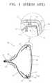
- FIGS. 1 and 2are a sectional view of a typical color CRT and an exploded perspective view showing a shadow mask frame assembly for a color CRT installed at the color CRT, respectively.
- a typical color CRTincludes a panel 11 on an inner surface of which a fluorescent film 11 a is formed, and a funnel 30 coupled to the panel 11 .
- An electron gun 15is installed at a neck portion 14 of the funnel 30 and a deflection yoke 20 is installed at a cone portion 12 of the funnel 30 .
- the typical color CRThas a shadow mask frame 10 .
- the shadow mask frame 10includes a shadow mask 16 installed to be separated a predetermined distance from the fluorescent film 11 a, a frame 17 supporting the shadow mask 16 , and an inner shield 21 of a rectangular funnel shape which is coupled to the frame 17 .
- a skirt portion 17 a for supporting the shadow mask 16 by being welded theretois formed at the frame 17 .
- a flange portion 17 b bent toward the inner sideis extended from the skirt portion 17 a so that the flange portion 17 b is coupled to the inner shield 21 .
- the shadow mask 16includes a hole portion 16 c having a plurality of electron beam passing holes, a hole-free portion 16 b extending from the edge of the hole portion 16 c , and a bending portion 16 a extending downward at a right angle from the hole-free portion 16 b and fixed to the skirt portion 17 a.
- a hook spring 19 fixed to the outer surface of the frame 17is coupled to a stud 18 installed on the inner surface of the panel 11 and the shadow mask frame assembly 10 is installed at the inner surface of the panel 11 .
- the weight of the frame 17increases as the size of the color CRT increases.
- a panel member having a thickness of about 1.2 mmis used for the color CRT less than 14 inches whereas a thin panel having a thickness of about 0.8 mm is used for a color CRT about 14-29 inches to reduce the weight thereof.
- the support force of the frame 17 to the shadow mask 16decreases so that the shadow mask 16 is deformed when an external impact is applied or during the manufacturing process.
- an electron beam emitted from the electron gunis selectively deflected by the deflection yoke 20 and passes through the holes of the shadow mask 16 for color selection, and excites the fluorescent film 11 a .
- the electron beam input to the edge of the shadow mask 16is reflected on the flange portion 17 b , generating diffusion-reflection.
- the diffused electron beampasses through the electron beam passing hole of the shadow mask 16 and excites an undesired pixel.
- a shadow mask/frame assembly for a color CRTwhich comprises a shadow mask including a hole portion having a predetermined curvature where a plurality of electron beam passing holes are formed and a bending portion extending from the edge of the hole portion by being bent at a predetermined angle, and a frame including a skirt portion coupled to the bending portion of the shadow mask, a flange portion extending from the skirt portion by being bent at a right angle thereto, a connection portion extending downward from the flange portion, and an extension portion extending from the connection portion, parallel to the flange portion.
- an end portion of the extension portionhas a knife edge shape for allowing an electron beam colliding with the extension portion to be diffusely reflected to the area except for the hole portion.
- FIG. 1is a sectional view of a typical color CRT
- FIG. 2is an exploded perspective view showing the frame assembly of a shadow mask for a typical color CRT;
- FIG. 3is a perspective view showing a shadow mask/frame assembly for a color CRT according to a preferred embodiment of the present invention.
- FIG. 4is a perspective view showing a shadow mask/frame assembly for a color CRT according to another preferred embodiment of the present invention.
- a shadow mask/frame assembly 30 for a color CRTincludes a shadow mask 26 and a frame 27 which are coupled to each other.
- the shadow mask 26includes a hole portion having a predetermined curvature, where a plurality of electron beam passing holes are formed, and a bending portion 26 a extending from the edge of the hole portion by being bent at a predetermined angle.
- the shadow mask 26is installed in a panel (not shown) and has a color selection function.
- the frame 27includes a skirt portion 27 a coupled to the bending portion 26 a of the shadow mask 26 , a flange portion 27 b extended from the skirt portion 27 a by being bent at a right angle thereto, a connection portion 27 c extending from the edge of the flange portion 27 b , and an extension portion extended from the connection portion 27 c parallel to the flange portion 27 b .
- an end portion 27 f of the extension portion 27 dis preferably formed to have a knife edge shape to diffusion-reflect an electron beam emitted from an electron gun to the area except for the hole portion of the shadow mask 26 .
- the bending portion 26 a of the shadow mask 26is fixedly welded to the skirt portion 27 a of the frame 27 .
- the shadow mask/frame assembly 30is installed at the panel as the hook spring 19 fixed to the outer circumferential surface of the frame 27 is coupled to the stud ( 18 of FIG. 1) installed at the inner surface of the panel. It is the same as that depicted in FIG. 1 .
- the inner shield(not shown) is coupled to the flange portion 27 b of the frame 27 of the shadow mask/frame assembly 30 installed at the panel.
- the frame 27is blocks the diffusion-reflection of the electron beam emitted from the electron gun and also reinforces the strength of the frame 27 . That is, an inclined surface of the knife edge shaped end portion 27 f of the extension portion 27 d diffusely reflects the electron beam toward the area except for the hole portion. Thus, when the electron beam is not input to the hole portion and collides with the knife edge shaped end portion 27 f , the electron beam is diffusely reflected to the area except for the hole portion by the inclined surface so that the fluorescent film of undesired other colors can be prevented from being excited.
- an electron beam colliding with the knife edge shaped end portion 27 fis prevented from being input to the shadow mask 26 , and only a normal electron beam is input to the shadow mask 26 and passes through the electron beam passing hole formed in the shadow mask 26 to be scanned on the fluorescent film to form an image.
- the extension portion 27 dis connected to the flange portion 27 b through the connection portion 27 c , forming a step, and serves as a bead.
- the structural strength of the frame 27can be improved.
- the fame 27 having a structure of being bent into multiple stepscan prevent the shadow mask 26 from being vibrated by external vibrations or a small impact.
- FIG. 4shows a shadow mask/frame assembly for a color CRT according to another preferred embodiment of the present invention.
- a shadow mask/frame assembly 40according to the present embodiment includes a frame 47 having an extension portion 47 d contacting the lower surface of a flange portion 47 b and parallel to the flange portion 47 b.
- the flange portion 47 b and the extension portion 47 dare separately manufactured and combined through spot welding.
- other structure, and effects thereofare the same as those of the embodiment described above, a detailed description of the present embodiment will be omitted.
- the extension portionis formed at the end of the flange portion to have a step
- the structural intensity of the frameis improved so that a relatively thin frame can be manufactured.
- the electron beam emitted from the electron gun colliding with the edge of the flange portioncan be prevented from exciting the fluorescent film of the other colors.
Landscapes
- Electrodes For Cathode-Ray Tubes (AREA)
Abstract
Description
Claims (4)
Applications Claiming Priority (2)
| Application Number | Priority Date | Filing Date | Title |
|---|---|---|---|
| KR1019990019758AKR100297699B1 (en) | 1999-05-31 | 1999-05-31 | Shadow mask/frame assembly for CPT |
| KR99-19758 | 1999-05-31 |
Publications (1)
| Publication Number | Publication Date |
|---|---|
| US6417608B1true US6417608B1 (en) | 2002-07-09 |
Family
ID=19588788
Family Applications (1)
| Application Number | Title | Priority Date | Filing Date |
|---|---|---|---|
| US09/580,973Expired - Fee RelatedUS6417608B1 (en) | 1999-05-31 | 2000-05-30 | Shadow mask/frame assembly for color cathode ray tube |
Country Status (3)
| Country | Link |
|---|---|
| US (1) | US6417608B1 (en) |
| KR (1) | KR100297699B1 (en) |
| CN (1) | CN1276618A (en) |
Cited By (2)
| Publication number | Priority date | Publication date | Assignee | Title |
|---|---|---|---|---|
| US6590326B2 (en)* | 2000-12-21 | 2003-07-08 | Thomson Licensing S. A. | Apparatus for maintaining tension in a shadow mask |
| US20080150891A1 (en)* | 2006-12-01 | 2008-06-26 | Mimic Technologies, Inc. | Methods, apparatus, and article for force feedback based on tension control and tracking through cables |
Citations (3)
| Publication number | Priority date | Publication date | Assignee | Title |
|---|---|---|---|---|
| US4737681A (en)* | 1986-05-21 | 1988-04-12 | Zenith Electronics Corporation | Support means for a tensioned foil shadow mask |
| USRE33253E (en)* | 1986-05-21 | 1990-07-03 | Zenith Electronics Corporation | Component mounting means for a tension mask color cathode ray tube |
| US4994712A (en)* | 1989-05-03 | 1991-02-19 | Zenith Electronics Corporation | Foil shadow mask mounting with low thermal expansion coefficient |
- 1999
- 1999-05-31KRKR1019990019758Apatent/KR100297699B1/ennot_activeExpired - Fee Related
- 2000
- 2000-05-30USUS09/580,973patent/US6417608B1/ennot_activeExpired - Fee Related
- 2000-05-31CNCN00120150Apatent/CN1276618A/enactivePending
Patent Citations (3)
| Publication number | Priority date | Publication date | Assignee | Title |
|---|---|---|---|---|
| US4737681A (en)* | 1986-05-21 | 1988-04-12 | Zenith Electronics Corporation | Support means for a tensioned foil shadow mask |
| USRE33253E (en)* | 1986-05-21 | 1990-07-03 | Zenith Electronics Corporation | Component mounting means for a tension mask color cathode ray tube |
| US4994712A (en)* | 1989-05-03 | 1991-02-19 | Zenith Electronics Corporation | Foil shadow mask mounting with low thermal expansion coefficient |
Cited By (2)
| Publication number | Priority date | Publication date | Assignee | Title |
|---|---|---|---|---|
| US6590326B2 (en)* | 2000-12-21 | 2003-07-08 | Thomson Licensing S. A. | Apparatus for maintaining tension in a shadow mask |
| US20080150891A1 (en)* | 2006-12-01 | 2008-06-26 | Mimic Technologies, Inc. | Methods, apparatus, and article for force feedback based on tension control and tracking through cables |
Also Published As
| Publication number | Publication date |
|---|---|
| KR100297699B1 (en) | 2001-09-26 |
| KR20000075252A (en) | 2000-12-15 |
| CN1276618A (en) | 2000-12-13 |
Similar Documents
| Publication | Publication Date | Title |
|---|---|---|
| US4072876A (en) | Corrugated shadow mask assembly for a cathode ray tube | |
| JPH1154063A (en) | Shadow mask frame assembly for cathode-ray tube | |
| US6417608B1 (en) | Shadow mask/frame assembly for color cathode ray tube | |
| US6037709A (en) | Cathode ray tube | |
| US6635981B2 (en) | Color cathode ray tube with mask frame having beads for rigidity | |
| US4367430A (en) | Shadow mask type color cathode-ray tube | |
| JPH0660822A (en) | Cathod-ray tube | |
| US4700105A (en) | Shadow mask mount for color picture tube | |
| US6828716B2 (en) | Shadow mask for color CRT | |
| US6218772B1 (en) | Color cathode-ray tube with shadow mask mounting system | |
| US6707242B2 (en) | Color cathode ray tube | |
| US6411024B1 (en) | Color picture tube | |
| CN1204854A (en) | Shadow mask frame assembly for color cathode ray tube | |
| US5818161A (en) | Electron gun cathode holder with manufacturing holes | |
| US6700319B2 (en) | Cathode-ray tube having a tension mask with microphonics control | |
| EP1001446A1 (en) | Color crt, elastic supporter for color crt and elastic support mechanism | |
| US7002286B2 (en) | Shadow mask frame assembly with etching portion and color cathode-ray tube having the same | |
| KR100395809B1 (en) | Shadow mask frame assembly | |
| KR200151015Y1 (en) | Cathode-ray tube | |
| KR100360503B1 (en) | Color cathode-ray tube with expanded effective display area | |
| KR20010040222A (en) | Shadow mask assembly for use in a color crt | |
| KR20040055422A (en) | Mask-frame assembly and cathode ray tube comprising it | |
| GB2238423A (en) | Shadow mask for a cathode-ray tube | |
| KR100470337B1 (en) | Shadowmask for color CRT | |
| JP2003229071A (en) | Shadow mask and color cathode ray tube |
Legal Events
| Date | Code | Title | Description |
|---|---|---|---|
| AS | Assignment | Owner name:SAMSUNG SDI CO., LTD., KOREA, REPUBLIC OF Free format text:(ASSIGNMENT OF ASSIGNOR'S INTEREST) RE-RECORD TO CORRECT THE NUMBER OF MICROFILM PAGES FROM 2 TO 3 AT REEL 10833, FRAME 0547.;ASSIGNORS:CHOI, DAI-OK;KIM, DONG-HWAN;PARK, YOUNG-KOOK;AND OTHERS;REEL/FRAME:011024/0681 Effective date:20000523 Owner name:SAMSUNG SDI CO., LTD., KOREA, REPUBLIC OF Free format text:INVALID RECORDING;ASSIGNORS:CHOI, DAI-OK;KIM, DONG-HWAN;PARK, YOUNG-KOOK;REEL/FRAME:010833/0547 Effective date:20000523 | |
| AS | Assignment | Owner name:SAMSUNG SDI CO., LTD., KOREA, REPUBLIC OF Free format text:ASSIGNMENT OF ASSIGNORS INTEREST;ASSIGNORS:CHOI, DAI-OK;KIM, DONG-HWAN;PARK, YOUNG-KOOK;AND OTHERS;REEL/FRAME:012766/0157 Effective date:20000523 | |
| REMI | Maintenance fee reminder mailed | ||
| LAPS | Lapse for failure to pay maintenance fees | ||
| STCH | Information on status: patent discontinuation | Free format text:PATENT EXPIRED DUE TO NONPAYMENT OF MAINTENANCE FEES UNDER 37 CFR 1.362 | |
| FP | Lapsed due to failure to pay maintenance fee | Effective date:20060709 |