US6416872B1 - Heat reflecting film with low visible reflectance - Google Patents
Heat reflecting film with low visible reflectanceDownload PDFInfo
- Publication number
- US6416872B1 US6416872B1US09/651,082US65108200AUS6416872B1US 6416872 B1US6416872 B1US 6416872B1US 65108200 AUS65108200 AUS 65108200AUS 6416872 B1US6416872 B1US 6416872B1
- Authority
- US
- United States
- Prior art keywords
- layer
- index
- refraction
- composite
- reflective
- Prior art date
- Legal status (The legal status is an assumption and is not a legal conclusion. Google has not performed a legal analysis and makes no representation as to the accuracy of the status listed.)
- Expired - Lifetime, expires
Links
Images


Classifications
- C—CHEMISTRY; METALLURGY
- C03—GLASS; MINERAL OR SLAG WOOL
- C03C—CHEMICAL COMPOSITION OF GLASSES, GLAZES OR VITREOUS ENAMELS; SURFACE TREATMENT OF GLASS; SURFACE TREATMENT OF FIBRES OR FILAMENTS MADE FROM GLASS, MINERALS OR SLAGS; JOINING GLASS TO GLASS OR OTHER MATERIALS
- C03C17/00—Surface treatment of glass, not in the form of fibres or filaments, by coating
- C03C17/34—Surface treatment of glass, not in the form of fibres or filaments, by coating with at least two coatings having different compositions
- C03C17/36—Surface treatment of glass, not in the form of fibres or filaments, by coating with at least two coatings having different compositions at least one coating being a metal
- C03C17/3602—Surface treatment of glass, not in the form of fibres or filaments, by coating with at least two coatings having different compositions at least one coating being a metal the metal being present as a layer
- C03C17/3615—Coatings of the type glass/metal/other inorganic layers, at least one layer being non-metallic
- B—PERFORMING OPERATIONS; TRANSPORTING
- B32—LAYERED PRODUCTS
- B32B—LAYERED PRODUCTS, i.e. PRODUCTS BUILT-UP OF STRATA OF FLAT OR NON-FLAT, e.g. CELLULAR OR HONEYCOMB, FORM
- B32B17/00—Layered products essentially comprising sheet glass, or glass, slag, or like fibres
- B32B17/06—Layered products essentially comprising sheet glass, or glass, slag, or like fibres comprising glass as the main or only constituent of a layer, next to another layer of a specific material
- B32B17/10—Layered products essentially comprising sheet glass, or glass, slag, or like fibres comprising glass as the main or only constituent of a layer, next to another layer of a specific material of synthetic resin
- B32B17/10005—Layered products essentially comprising sheet glass, or glass, slag, or like fibres comprising glass as the main or only constituent of a layer, next to another layer of a specific material of synthetic resin laminated safety glass or glazing
- B32B17/10165—Functional features of the laminated safety glass or glazing
- B32B17/10174—Coatings of a metallic or dielectric material on a constituent layer of glass or polymer
- C—CHEMISTRY; METALLURGY
- C03—GLASS; MINERAL OR SLAG WOOL
- C03C—CHEMICAL COMPOSITION OF GLASSES, GLAZES OR VITREOUS ENAMELS; SURFACE TREATMENT OF GLASS; SURFACE TREATMENT OF FIBRES OR FILAMENTS MADE FROM GLASS, MINERALS OR SLAGS; JOINING GLASS TO GLASS OR OTHER MATERIALS
- C03C17/00—Surface treatment of glass, not in the form of fibres or filaments, by coating
- C03C17/34—Surface treatment of glass, not in the form of fibres or filaments, by coating with at least two coatings having different compositions
- C03C17/3411—Surface treatment of glass, not in the form of fibres or filaments, by coating with at least two coatings having different compositions with at least two coatings of inorganic materials
- C03C17/3429—Surface treatment of glass, not in the form of fibres or filaments, by coating with at least two coatings having different compositions with at least two coatings of inorganic materials at least one of the coatings being a non-oxide coating
- C03C17/3435—Surface treatment of glass, not in the form of fibres or filaments, by coating with at least two coatings having different compositions with at least two coatings of inorganic materials at least one of the coatings being a non-oxide coating comprising a nitride, oxynitride, boronitride or carbonitride
- C—CHEMISTRY; METALLURGY
- C03—GLASS; MINERAL OR SLAG WOOL
- C03C—CHEMICAL COMPOSITION OF GLASSES, GLAZES OR VITREOUS ENAMELS; SURFACE TREATMENT OF GLASS; SURFACE TREATMENT OF FIBRES OR FILAMENTS MADE FROM GLASS, MINERALS OR SLAGS; JOINING GLASS TO GLASS OR OTHER MATERIALS
- C03C17/00—Surface treatment of glass, not in the form of fibres or filaments, by coating
- C03C17/34—Surface treatment of glass, not in the form of fibres or filaments, by coating with at least two coatings having different compositions
- C03C17/36—Surface treatment of glass, not in the form of fibres or filaments, by coating with at least two coatings having different compositions at least one coating being a metal
- C03C17/3602—Surface treatment of glass, not in the form of fibres or filaments, by coating with at least two coatings having different compositions at least one coating being a metal the metal being present as a layer
- C03C17/3618—Coatings of type glass/inorganic compound/other inorganic layers, at least one layer being metallic
- C—CHEMISTRY; METALLURGY
- C03—GLASS; MINERAL OR SLAG WOOL
- C03C—CHEMICAL COMPOSITION OF GLASSES, GLAZES OR VITREOUS ENAMELS; SURFACE TREATMENT OF GLASS; SURFACE TREATMENT OF FIBRES OR FILAMENTS MADE FROM GLASS, MINERALS OR SLAGS; JOINING GLASS TO GLASS OR OTHER MATERIALS
- C03C17/00—Surface treatment of glass, not in the form of fibres or filaments, by coating
- C03C17/34—Surface treatment of glass, not in the form of fibres or filaments, by coating with at least two coatings having different compositions
- C03C17/36—Surface treatment of glass, not in the form of fibres or filaments, by coating with at least two coatings having different compositions at least one coating being a metal
- C03C17/3602—Surface treatment of glass, not in the form of fibres or filaments, by coating with at least two coatings having different compositions at least one coating being a metal the metal being present as a layer
- C03C17/3626—Surface treatment of glass, not in the form of fibres or filaments, by coating with at least two coatings having different compositions at least one coating being a metal the metal being present as a layer one layer at least containing a nitride, oxynitride, boronitride or carbonitride
- C—CHEMISTRY; METALLURGY
- C03—GLASS; MINERAL OR SLAG WOOL
- C03C—CHEMICAL COMPOSITION OF GLASSES, GLAZES OR VITREOUS ENAMELS; SURFACE TREATMENT OF GLASS; SURFACE TREATMENT OF FIBRES OR FILAMENTS MADE FROM GLASS, MINERALS OR SLAGS; JOINING GLASS TO GLASS OR OTHER MATERIALS
- C03C17/00—Surface treatment of glass, not in the form of fibres or filaments, by coating
- C03C17/34—Surface treatment of glass, not in the form of fibres or filaments, by coating with at least two coatings having different compositions
- C03C17/36—Surface treatment of glass, not in the form of fibres or filaments, by coating with at least two coatings having different compositions at least one coating being a metal
- C03C17/3602—Surface treatment of glass, not in the form of fibres or filaments, by coating with at least two coatings having different compositions at least one coating being a metal the metal being present as a layer
- C03C17/3634—Surface treatment of glass, not in the form of fibres or filaments, by coating with at least two coatings having different compositions at least one coating being a metal the metal being present as a layer one layer at least containing carbon, a carbide or oxycarbide
- C—CHEMISTRY; METALLURGY
- C03—GLASS; MINERAL OR SLAG WOOL
- C03C—CHEMICAL COMPOSITION OF GLASSES, GLAZES OR VITREOUS ENAMELS; SURFACE TREATMENT OF GLASS; SURFACE TREATMENT OF FIBRES OR FILAMENTS MADE FROM GLASS, MINERALS OR SLAGS; JOINING GLASS TO GLASS OR OTHER MATERIALS
- C03C17/00—Surface treatment of glass, not in the form of fibres or filaments, by coating
- C03C17/34—Surface treatment of glass, not in the form of fibres or filaments, by coating with at least two coatings having different compositions
- C03C17/36—Surface treatment of glass, not in the form of fibres or filaments, by coating with at least two coatings having different compositions at least one coating being a metal
- C03C17/3602—Surface treatment of glass, not in the form of fibres or filaments, by coating with at least two coatings having different compositions at least one coating being a metal the metal being present as a layer
- C03C17/3636—Surface treatment of glass, not in the form of fibres or filaments, by coating with at least two coatings having different compositions at least one coating being a metal the metal being present as a layer one layer at least containing silicon, hydrogenated silicon or a silicide
- C—CHEMISTRY; METALLURGY
- C03—GLASS; MINERAL OR SLAG WOOL
- C03C—CHEMICAL COMPOSITION OF GLASSES, GLAZES OR VITREOUS ENAMELS; SURFACE TREATMENT OF GLASS; SURFACE TREATMENT OF FIBRES OR FILAMENTS MADE FROM GLASS, MINERALS OR SLAGS; JOINING GLASS TO GLASS OR OTHER MATERIALS
- C03C17/00—Surface treatment of glass, not in the form of fibres or filaments, by coating
- C03C17/34—Surface treatment of glass, not in the form of fibres or filaments, by coating with at least two coatings having different compositions
- C03C17/36—Surface treatment of glass, not in the form of fibres or filaments, by coating with at least two coatings having different compositions at least one coating being a metal
- C03C17/3602—Surface treatment of glass, not in the form of fibres or filaments, by coating with at least two coatings having different compositions at least one coating being a metal the metal being present as a layer
- C03C17/3639—Multilayers containing at least two functional metal layers
- C—CHEMISTRY; METALLURGY
- C03—GLASS; MINERAL OR SLAG WOOL
- C03C—CHEMICAL COMPOSITION OF GLASSES, GLAZES OR VITREOUS ENAMELS; SURFACE TREATMENT OF GLASS; SURFACE TREATMENT OF FIBRES OR FILAMENTS MADE FROM GLASS, MINERALS OR SLAGS; JOINING GLASS TO GLASS OR OTHER MATERIALS
- C03C17/00—Surface treatment of glass, not in the form of fibres or filaments, by coating
- C03C17/34—Surface treatment of glass, not in the form of fibres or filaments, by coating with at least two coatings having different compositions
- C03C17/36—Surface treatment of glass, not in the form of fibres or filaments, by coating with at least two coatings having different compositions at least one coating being a metal
- C03C17/3602—Surface treatment of glass, not in the form of fibres or filaments, by coating with at least two coatings having different compositions at least one coating being a metal the metal being present as a layer
- C03C17/3642—Surface treatment of glass, not in the form of fibres or filaments, by coating with at least two coatings having different compositions at least one coating being a metal the metal being present as a layer the multilayer coating containing a metal layer
- C—CHEMISTRY; METALLURGY
- C03—GLASS; MINERAL OR SLAG WOOL
- C03C—CHEMICAL COMPOSITION OF GLASSES, GLAZES OR VITREOUS ENAMELS; SURFACE TREATMENT OF GLASS; SURFACE TREATMENT OF FIBRES OR FILAMENTS MADE FROM GLASS, MINERALS OR SLAGS; JOINING GLASS TO GLASS OR OTHER MATERIALS
- C03C17/00—Surface treatment of glass, not in the form of fibres or filaments, by coating
- C03C17/34—Surface treatment of glass, not in the form of fibres or filaments, by coating with at least two coatings having different compositions
- C03C17/36—Surface treatment of glass, not in the form of fibres or filaments, by coating with at least two coatings having different compositions at least one coating being a metal
- C03C17/3602—Surface treatment of glass, not in the form of fibres or filaments, by coating with at least two coatings having different compositions at least one coating being a metal the metal being present as a layer
- C03C17/3644—Surface treatment of glass, not in the form of fibres or filaments, by coating with at least two coatings having different compositions at least one coating being a metal the metal being present as a layer the metal being silver
- C—CHEMISTRY; METALLURGY
- C03—GLASS; MINERAL OR SLAG WOOL
- C03C—CHEMICAL COMPOSITION OF GLASSES, GLAZES OR VITREOUS ENAMELS; SURFACE TREATMENT OF GLASS; SURFACE TREATMENT OF FIBRES OR FILAMENTS MADE FROM GLASS, MINERALS OR SLAGS; JOINING GLASS TO GLASS OR OTHER MATERIALS
- C03C17/00—Surface treatment of glass, not in the form of fibres or filaments, by coating
- C03C17/34—Surface treatment of glass, not in the form of fibres or filaments, by coating with at least two coatings having different compositions
- C03C17/36—Surface treatment of glass, not in the form of fibres or filaments, by coating with at least two coatings having different compositions at least one coating being a metal
- C03C17/3602—Surface treatment of glass, not in the form of fibres or filaments, by coating with at least two coatings having different compositions at least one coating being a metal the metal being present as a layer
- C03C17/3649—Surface treatment of glass, not in the form of fibres or filaments, by coating with at least two coatings having different compositions at least one coating being a metal the metal being present as a layer made of metals other than silver
- C—CHEMISTRY; METALLURGY
- C03—GLASS; MINERAL OR SLAG WOOL
- C03C—CHEMICAL COMPOSITION OF GLASSES, GLAZES OR VITREOUS ENAMELS; SURFACE TREATMENT OF GLASS; SURFACE TREATMENT OF FIBRES OR FILAMENTS MADE FROM GLASS, MINERALS OR SLAGS; JOINING GLASS TO GLASS OR OTHER MATERIALS
- C03C17/00—Surface treatment of glass, not in the form of fibres or filaments, by coating
- C03C17/34—Surface treatment of glass, not in the form of fibres or filaments, by coating with at least two coatings having different compositions
- C03C17/36—Surface treatment of glass, not in the form of fibres or filaments, by coating with at least two coatings having different compositions at least one coating being a metal
- C03C17/3602—Surface treatment of glass, not in the form of fibres or filaments, by coating with at least two coatings having different compositions at least one coating being a metal the metal being present as a layer
- C03C17/3652—Surface treatment of glass, not in the form of fibres or filaments, by coating with at least two coatings having different compositions at least one coating being a metal the metal being present as a layer the coating stack containing at least one sacrificial layer to protect the metal from oxidation
- C—CHEMISTRY; METALLURGY
- C03—GLASS; MINERAL OR SLAG WOOL
- C03C—CHEMICAL COMPOSITION OF GLASSES, GLAZES OR VITREOUS ENAMELS; SURFACE TREATMENT OF GLASS; SURFACE TREATMENT OF FIBRES OR FILAMENTS MADE FROM GLASS, MINERALS OR SLAGS; JOINING GLASS TO GLASS OR OTHER MATERIALS
- C03C17/00—Surface treatment of glass, not in the form of fibres or filaments, by coating
- C03C17/34—Surface treatment of glass, not in the form of fibres or filaments, by coating with at least two coatings having different compositions
- C03C17/36—Surface treatment of glass, not in the form of fibres or filaments, by coating with at least two coatings having different compositions at least one coating being a metal
- C03C17/3602—Surface treatment of glass, not in the form of fibres or filaments, by coating with at least two coatings having different compositions at least one coating being a metal the metal being present as a layer
- C03C17/3657—Surface treatment of glass, not in the form of fibres or filaments, by coating with at least two coatings having different compositions at least one coating being a metal the metal being present as a layer the multilayer coating having optical properties
- C03C17/366—Low-emissivity or solar control coatings
- C—CHEMISTRY; METALLURGY
- C03—GLASS; MINERAL OR SLAG WOOL
- C03C—CHEMICAL COMPOSITION OF GLASSES, GLAZES OR VITREOUS ENAMELS; SURFACE TREATMENT OF GLASS; SURFACE TREATMENT OF FIBRES OR FILAMENTS MADE FROM GLASS, MINERALS OR SLAGS; JOINING GLASS TO GLASS OR OTHER MATERIALS
- C03C17/00—Surface treatment of glass, not in the form of fibres or filaments, by coating
- C03C17/34—Surface treatment of glass, not in the form of fibres or filaments, by coating with at least two coatings having different compositions
- C03C17/36—Surface treatment of glass, not in the form of fibres or filaments, by coating with at least two coatings having different compositions at least one coating being a metal
- C03C17/3602—Surface treatment of glass, not in the form of fibres or filaments, by coating with at least two coatings having different compositions at least one coating being a metal the metal being present as a layer
- C03C17/3681—Surface treatment of glass, not in the form of fibres or filaments, by coating with at least two coatings having different compositions at least one coating being a metal the metal being present as a layer the multilayer coating being used in glazing, e.g. windows or windscreens
- C—CHEMISTRY; METALLURGY
- C03—GLASS; MINERAL OR SLAG WOOL
- C03C—CHEMICAL COMPOSITION OF GLASSES, GLAZES OR VITREOUS ENAMELS; SURFACE TREATMENT OF GLASS; SURFACE TREATMENT OF FIBRES OR FILAMENTS MADE FROM GLASS, MINERALS OR SLAGS; JOINING GLASS TO GLASS OR OTHER MATERIALS
- C03C17/00—Surface treatment of glass, not in the form of fibres or filaments, by coating
- C03C17/34—Surface treatment of glass, not in the form of fibres or filaments, by coating with at least two coatings having different compositions
- C03C17/36—Surface treatment of glass, not in the form of fibres or filaments, by coating with at least two coatings having different compositions at least one coating being a metal
- C03C17/38—Surface treatment of glass, not in the form of fibres or filaments, by coating with at least two coatings having different compositions at least one coating being a metal at least one coating being a coating of an organic material
- C—CHEMISTRY; METALLURGY
- C03—GLASS; MINERAL OR SLAG WOOL
- C03C—CHEMICAL COMPOSITION OF GLASSES, GLAZES OR VITREOUS ENAMELS; SURFACE TREATMENT OF GLASS; SURFACE TREATMENT OF FIBRES OR FILAMENTS MADE FROM GLASS, MINERALS OR SLAGS; JOINING GLASS TO GLASS OR OTHER MATERIALS
- C03C17/00—Surface treatment of glass, not in the form of fibres or filaments, by coating
- C03C17/34—Surface treatment of glass, not in the form of fibres or filaments, by coating with at least two coatings having different compositions
- C03C17/42—Surface treatment of glass, not in the form of fibres or filaments, by coating with at least two coatings having different compositions at least one coating of an organic material and at least one non-metal coating
- G—PHYSICS
- G02—OPTICS
- G02B—OPTICAL ELEMENTS, SYSTEMS OR APPARATUS
- G02B1/00—Optical elements characterised by the material of which they are made; Optical coatings for optical elements
- G02B1/10—Optical coatings produced by application to, or surface treatment of, optical elements
- G—PHYSICS
- G02—OPTICS
- G02B—OPTICAL ELEMENTS, SYSTEMS OR APPARATUS
- G02B1/00—Optical elements characterised by the material of which they are made; Optical coatings for optical elements
- G02B1/10—Optical coatings produced by application to, or surface treatment of, optical elements
- G02B1/11—Anti-reflection coatings
- G02B1/113—Anti-reflection coatings using inorganic layer materials only
- G02B1/115—Multilayers
- G02B1/116—Multilayers including electrically conducting layers
Definitions
- This inventionrelates generally to heat reflecting fenestration composites and, more particularly, to such composites of the dielectric-metal-dielectric type.
- heat reflecting fenestration compositeshave been in use to improve the energy transmission and appearance of transparent glazing used in commercial buildings, residential buildings and vehicles.
- the purpose for using these heat reflecting fenestration compositesis generally to alter the solar energy transmission, reflection, absorption or emission of various glazing products.
- the most common purpose for using heat reflecting fenestration compositesis to reduce solar heat gain by reflecting or absorbing as much infrared energy as possible without degrading the visible characteristics of the fenestration structure. It is usually desirable to create a transparent glazing with high to medium visible transmission and low visible reflection on both sides of the energy control sheet. It is also desirable that transmission and reflection on either side of the sheet are neutral to slightly blue-green in color. Implementing these properties in a glazing is usually done with optical thin film coatings vacuum deposited on one surface of a transparent glazing material.
- a typical heat reflecting thin film productis a five layer thin film structure consisting of: dielectric/infrared reflecting metal/dielectric/infrared reflecting metal/dielectric (“D/M/D/M”). Layer thicknesses and material choices for this design must be specifically controlled to achieve the desired optical spectrum.
- the dielectric layerstypically chosen have high indices of refraction ranging from 1.8 to 2.5 and are often materials such as In 2 O 3 , SnO 2 , TiO 2 , Nb 2 O 5 , Ta 2 O 5 , ZnO and SiN. Designs using lower index dielectric materials such as polymers are known but less commonly made.
- the infrared reflecting layerstypically consist of silver or alloys of silver but may be variations of gold, copper or even conductive compounds such as titanium nitride.
- this heat reflecting interference stackincludes designs with more or less metal/dielectric pairs. Three-layer (D/M/D) and seven-layer (D/M/D/M/D/M/D) designs are also commonly employed.
- Three-layer designsare much less expensive to manufacture than five-layer designs and seven-layer designs, but have traditionally suffered from several disadvantages.
- three-layer designsexhibit desirable low visible reflectance levels less than 10%) only when the substrate and one surface of the thin film layer are left exposed to air.
- visible reflectanceoften rises to levels of 13 to 25%, levels which are undesirable in many applications.
- the reason for this differencehas to do with the optical coupling of the three-layer stack with air (having a reflective index of 1.0) versus the coupling with polymer (having a reflective index of 1.4-1.7).
- the present inventionsatisfies this need.
- the inventionis a heat reflective composite comprising, in series, a first substrate and a heat reflective stack disposed upon the first substrate.
- the heat reflective stackcomprises:
- non-infrared reflective layerdeposited onto the second interference layer, the non-infrared reflective layer being composed of a material selected from the group of materials consisting of (i) metals having an index of refraction greater than about 1.0 and an extinction coefficient greater than about 2.0 and (ii) non-metals having an index of refraction greater than about 0.5 and having an extinction coefficient greater than about 0.5.
- the first substrateis a pane of glass or a thin plastic material which can be applied to a pane of glass.
- the first and second interference layersare typically dielectric materials, such as metal oxides having indices of refraction in the visible wavelengths between about 1.8 and about 2.5.
- the infrared reflecting metal layeris typically silver, gold, copper or alloys thereof.
- the non-infrared reflective layeris typically a layer of titanium, tantalum, niobium, chromium, molybdenum, stainless steel or nickel alloy.
- the inventionhas been found to provide an improved heat reflective stack which is effective even when one side of the heat reflective stack is not exposed to the air.
- the heat reflective stackis effective in reducing heat and light transmission without undue reflectance and without adversely affecting the color of transmitted light.
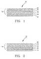
- FIG. 1is a cross-sectional side view of a heat-reflecting fenestration composite having features of the invention
- FIG. 2is a cross-sectional side view of a second heat-reflecting fenestration composite having features of the invention
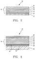
- FIG. 3is a cross-sectional side view of a third heat-reflecting fenestration composite having features of the invention
- FIG. 4is a cross-sectional side view of a fourth heat-reflecting fenestration composite having features of the invention.
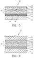
- FIG. 5is a cross-sectional side view of a fifth heat-reflecting fenestration composite having features of the invention.
- FIG. 6is a cross-sectional side view of a sixth heat-reflecting fenestration composite having features of the invention.
- FIG. 7is a cross-sectional side view of a seventh heat-reflecting fenestration composite having features of the invention.
- FIG. 8is a cross-sectional side view of an eighth heat-reflecting fenestration composite having features of the invention.
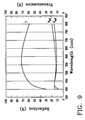
- FIG. 9is a graphical representation of spectral data obtained from a hypothetical typical three-layer composite of the prior art.
- FIG. 10is a graphical representation of spectral data obtained from a hypothetical typical three-layer composite having features of the invention.
- the inventionis a heat reflective composite 10 having a first substrate 12 and a unique heat reflective stack 14 disposed upon the first substrate 12 .
- the heat reflective stackcomprises a first interference layer 16 , an infrared reflecting metal layer 18 , a second interference layer 20 and a first non-infrared reflective layer 22 .
- FIGS. 1 and 2illustrate the invention 10 in its most basic form.
- the first substrate 12can be any light transmissive substance.
- the first reflective substrate 12is a pane of glass or a sheet of a transparent thermoplastic, such as polyethylene terephthalate (“PET”).
- PETpolyethylene terephthalate
- the index of refraction of the first substrate 12will typically be between about 1.4 and 1.7.
- the index of refraction for PETis approximately 1.65.
- the first substrate 12is a pane of glass
- the first substrate 12will have a typical have a thickness of between about 3 mm and about 6 mm.
- the thickness of the first substrate 12is typically between about 12 microns and about 300 microns.
- the first interference layer 16has an index of refraction which differs from the index of refraction of the first substrate 12 by at least about 0.1, most preferably by at least about 0.2.
- the first interference layer 16can be a metal oxide, such as an oxide of magnesium, aluminum, titanium, chromium, zinc, zirconium, niobium, molybdenum, indium, tin, tantalum, tungsten, bismuth or a combination of such oxides.
- the first interference layer 16can be a nitride of silicon or aluminum.
- the first interference layer 16can also be a polymer, such as a vacuum deposited acrylate.
- the first interference layer 16is zinc oxide, tin oxide or indium oxide, having an index of refraction between about 1.9 and about 2.1.
- the first interference layer 16has an extinction coefficient between about 0.0 and about 0.5.
- the first interference layer 16is deposited adjacent to the first substrate 12 in a thickness of between about 0.3 QWOT and about 1.0 QWOT.
- QWOTas used herein means “quarter wave optical thickness.”
- the physical thickness of the first interference layer 16is between about 20 mm and about 70 nm.
- the infrared reflecting metal layer 18is typically a layer of metal comprised of silver, gold, copper, aluminum, copper, alloys thereof or titanium nitride. In preferred embodiments, the infrared reflecting metal layer 18 is essentially silver or is an alloy of silver and copper or silver and gold. In one preferred embodiment, the infrared reflecting metal layer 18 is an alloy of silver and copper wherein the percentage of copper is between about 3 wt. % and about 20 wt. %.
- the heat reflective metal layer 18is deposited onto the first interference layer 18 in a thickness of between about 8 nm and about 20 nm, preferably between about 9 nm and about 15 nm.
- the heat reflective metal layer 18may further comprise one or more cladding layers, generally of a dissimilar metal, metal alloy, or metal compound, to protect the heat reflective metal from corrosion or other degradation processes.
- the second interference layer 20can be a metal oxide, such as an oxide of magnesium, aluminum, silicon, titanium, chromium, zinc, zirconium, niobium, molybdenum, indium, tin, tantalum, tungsten, bismuth or a combination of these oxides.
- the second interference layer 20can be a nitride of silicon or aluminum.
- the second interference layer 20can also be magnesium fluoride. Mixtures of these aforementioned materials can also be used in the second interference layer 20 .
- the second interference layer 20can also be a polymer, such as a vacuum deposited acrylate.
- the second interference layer 20is zinc oxide, tin oxide or indium oxide, having an index of refraction between about 1.9 and about 2.1.
- the second interference layer 20preferably has an extinction coefficient between about 0.0 and about 0.5.
- the second interference layer 20is deposited on the opposite side of the infrared reflecting metal layer 18 from the sides closest to the first interference layer 16 .
- the thickness of the second interference layer 20is typically between about 30 nm and about 120 nm, most typically between about 50 nm and about 90 nm.
- Both the first and second interference layers 16 and 20can be a single, homogeneous material.
- one or both of the interference layerscan be a mixture of different materials or two or more discreet layers, each comprising a different material.
- the first non-infrared reflective layer 22is deposited onto the second interference layer 20 .
- the first non-infrared reflective layer 22is composed of a material from one of the following groups of materials: (i) metals having an index o( refraction greater than about 1.0 in the visible wavelengths and an extinction coefficient greater than about 2.0, and (ii) non-metals having an index of refraction greater than about 0.5 and an extinction coefficient greater than about 0.5.
- the non-infrared reflective layer 22is essentially metallic, having an index of refraction between about 1.3 and about 3.0, and having an extinction coefficient between about 2.1 and about 4.0.
- the first non-infrared reflective layer 22is typically a titanium, tantalum, chromium, molybdenum, nickel alloy, stainless steel, mixtures thereof or a metal carbide, metal silicide or nitride such as tungsten doped titanium nitride.
- the first non-infrared reflective metal layer 22is stainless steel or nickel alloy due to their desirable optical properties of neutral gray color, low reflectance and high optical absorption.
- the first non-infrared reflective layer 22can be essentially non-metallic, such as first non-infrared reflective layers made from carbon, silicon, germanium, mixtures thereof, or compounds of these materials.
- the first non-infrared reflective layer 22has an extinction coefficient which increases with wavelengths in the visible wavelengths.
- the extinction coefficient of the first non-infrared reflective layer 22is 0.03 at 400 nm wavelength and 1.5 at 650 nm wavelength.
- FIG. 1illustrates a first basic-most embodiment of the invention 10 , wherein the first non-infrared reflective layer 22 is disposed upon the second interference layer 20 .
- FIG. 2illustrates an alternative basic-most embodiment, wherein the first non-infrared reflective layer 22 is disposed between the first substrate 12 and the first interference layer 16 .
- the heat reflective compositecomprises a second non-infrared reflective layer 24 disposed between the first substrate 12 and the first interference layer 16 .
- Such second non-infrared reflective layer 24can be made from the same materials as the first non-infrared reflective layer 22 .
- the second non-infrared reflective layer 24is essentially metallic, such as a nickel alloy, a stainless steel or a titanium alloy having an index of refraction between 1.3 and about 3.0.
- FIG. 4illustrates an embodiment of the invention useful as a retrofit product for application to a preexisting glass window pane 32 .
- a second substrate 28is disposed between the pane of glass 32 and the first interference layer 16 .
- the first substrate 12is disposed onto the first non-infrared reflecting layer 22 .
- a mounting adhesive layer 34is typically disposed between the second substrate 28 and the pane of glass 32 to improve adhesion between the second substrate 28 and the pane of glass 32 .
- the mounting adhesive layer 34is most usually an acrylic or polyester based adhesive.
- a laminating adhesive 35is typically disposed between the second substrate 28 and the first interference layer 16 to improve adhesive between those two layers.
- the laminating adhesive layer 35is most usually a polyester-based adhesive.
- Both the mounting adhesive layer 34 and the laminating adhesive layer 35are typically 1-5 microns thick.
- the composite layers(which include the first substrate 12 down through the second substrate 28 ) can be manufactured as a stand-alone laminate which can later be retrofitted onto a pane of glass 32 .
- the second substrate 28can be made from the same materials which can compose the first substrate 12 .
- the second substrate 28can be made from a material having an index of refraction between about 1.4 and about 1.7.
- the first substrate 12is a sheet of a thermoplastic, such as polyethylene terephthalate.
- a thermoplasticsuch as polyethylene terephthalate.
- the first substrate 12is polyethylene terephthalate, it is typical to provide the first substrate 12 with one of the many UV absorbers commonly used in the art.
- UV absorberprotects the composite 14 from degradation due to UV energy.
- the first substrate 12can include a benzophenone type ultraviolet light absorbing material, such as is manufactured by BASF Corporation.
- the invention 10further comprises a scratch-resistant coating 26 applied to the first substrate 12 .
- a typical scratch resistant coating 26is an acrylate, having a hardness greater than the substrate and applied by solvent coating between about 1 and about 10 microns in thickness.
- FIG. 5illustrates a low emissivity embodiment of the invention. This embodiment also illustrates use of the invention as a retrofit product for installation onto a preexisting pane of glass 32 .
- the composite 10includes a first substrate 12 and a second substrate 28 disposed contiguous with each other.
- a scratch-resistant coating 26is appended directly to the second non-infrared reflecting layer 22 .
- the composite layers between the second substrate 28 and the scratch-resisting coating 26can be manufactured as a stand-alone composite which can later be retrofitted onto the pane of glass 32 .
- FIG. 6illustrates an embodiment of the invention wherein the heat reflecting composite is disposed between a pair of glass panes 32 .
- a layer of polyvinylbutyral 36is disposed along the surface of each pane of glass 32 facing the composite layers.
- the layers of polyvinylbutyral 36form two functions. First, they act as an adhesive to improve adhesion with the glass panes 32 . Second, they impart additional mechanical s to the glass panes 32 . Such additional mechanical strength is important in automobile windows, hurricane windows and many other varieties of “safety glass.”
- FIGS. 7 and 8illustrate embodiments of the invention wherein the composite 10 is also disposed between two panes of glass 32 .
- the second pane of glass 32is disposed immediately adjacent to the first non-infrared reflecting layer 22 , but disposed apart therefrom by a gap 38 of between about 6 mm and about 20 mm.
- both panes of glass 32arm spaced apart from the composite by gaps 38 of between about 6 and about 15 mm.
- the panes of glass 32can be maintained spaced apart from one or both of the composite 14 by spacers such as those taught in U.S. Pat. No. 4,335,166, the entire of which is incorporated herein by this reference.
- the heat reflective composite 10 of the inventionreflects less than about 10% of visible light, preferably less than about 8% of visible light.
- the heat reflective composite 10 of the inventiontransmits less than about 70% of visible light, most preferably between about 40% and about 60%. It is also preferable that the heat reflective composite 10 reflects at least about 50% of electromagnetic radiation having a wavelength greater than 1200 nm, preferably at least about 70% of such radiation.
- the light transmitted through the heat reflective composite 10 of the inventionis of a neutral color. If not neutral, it is preferable that transmitted light have a slight blue-green transmission.
- These colorsmay be quantified by the CIE standardized scale of L*a*b* color space.
- CIErefers to the Commission International de l'Eclanage (i.e., the International Commission on Illumination). The CIE system is generally recognized in the industry.
- a* for a composite 10is preferably within the range from 0 and ⁇ 6, more preferably between 0 and ⁇ 4 and, more preferably between 0 and ⁇ 3, and b* for a composite 10 is preferably from 0 and ⁇ 3 or more preferably between 0 and ⁇ 2.
- Light reflected from the heat reflective composite 10should also be of a neutral color to slightly blue-green. That is, the reflected color range for both a* and b* is preferably between 0 and ⁇ 8, more preferably between 0 and ⁇ 6 and, most preferably, between 0 and ⁇ 3.
- Comparative exampleswere prepared using computer simulation techniques to test the benefits of the invention.
- a typical three-layer composite of the prior artwas simulated.
- an equivalent three-layer composite of the inventionwas simulated.
- the oxide thicknesses in both exampleswere appropriately adjusted to “tune” the composite for optimum performance.
- the resulting spectrums anticipated from the two exampleswere compared in FIGS. 9 and 10.
- a three-layer composite having features of the inventionwas simulated as follows:
- ReflectionIn the composite of the invention, the side of the composite where the non-infrared reflective layer is placed has significantly lower reflection than is achieved in the prior art composite. This reduced reflectance (and the ability to locate it on either or both sides of the composite) is a definite advantage. For most fenestration applications of heat reflecting composites, low reflectance is highly desirable on at least one side of the composite.
- ReflectionIn the composite of the invention, the side opposite the non-infrared reflective layer has somewhat increased reflection. When this higher reflectance side is placed towards the exterior, more solar energy is reflected. In this way, solar heat gain passing through a window using a composite of the invention is reduced. This, in turn, reduces cooling energy requirements on the interior of the window.
- the reflected light from the composite of the prior arthas a distinctly bluish-purple color (a* of 1.24 is slightly red, b* of ⁇ 5.23 is blue).
- reflected light from the composite of the inventionis considerably more neutral (both a* and b* being closer to zero).
- the inventionhas been found to provide an effective three-layer heat reflective stack, even when the heat reflective stack is not open to the air.
- the heat reflective stackis effective in reducing heat and light transmission without undue reflectance and without adversely affecting the color of transmitted light.
Landscapes
- Chemical & Material Sciences (AREA)
- Materials Engineering (AREA)
- Engineering & Computer Science (AREA)
- Chemical Kinetics & Catalysis (AREA)
- General Chemical & Material Sciences (AREA)
- Geochemistry & Mineralogy (AREA)
- Life Sciences & Earth Sciences (AREA)
- Organic Chemistry (AREA)
- Physics & Mathematics (AREA)
- General Physics & Mathematics (AREA)
- Optics & Photonics (AREA)
- Inorganic Chemistry (AREA)
- Laminated Bodies (AREA)
- Surface Treatment Of Glass (AREA)
Abstract
Description
| CIE Color Coordinates for Example 1 |
| Exterior Reflection | Interior Reflection | Transmission | ||
| a* | 1.24 | 1.31 | −3.15 |
| b* | −5.23 | −3.09 | 9.48 |
| CIE Color Coordinates for Example 2 |
| Exterior Reflection | Interior Reflection | Transmission | ||
| a* | 0.072 | 3.85 | −2.85 |
| b* | −1.62 | −9.29 | 6.43 |
Claims (26)
Priority Applications (4)
| Application Number | Priority Date | Filing Date | Title |
|---|---|---|---|
| US09/651,082US6416872B1 (en) | 2000-08-30 | 2000-08-30 | Heat reflecting film with low visible reflectance |
| AU2001284661AAU2001284661A1 (en) | 2000-08-30 | 2001-08-23 | Heat reflecting film with low visible refectance |
| PCT/US2001/022619WO2002018132A2 (en) | 2000-08-30 | 2001-08-23 | Heat reflecting film with low visible refectance |
| EP01963735AEP1313678A2 (en) | 2000-08-30 | 2001-08-23 | Heat reflecting film with low visible refectance |
Applications Claiming Priority (1)
| Application Number | Priority Date | Filing Date | Title |
|---|---|---|---|
| US09/651,082US6416872B1 (en) | 2000-08-30 | 2000-08-30 | Heat reflecting film with low visible reflectance |
Publications (1)
| Publication Number | Publication Date |
|---|---|
| US6416872B1true US6416872B1 (en) | 2002-07-09 |
Family
ID=24611507
Family Applications (1)
| Application Number | Title | Priority Date | Filing Date |
|---|---|---|---|
| US09/651,082Expired - LifetimeUS6416872B1 (en) | 2000-08-30 | 2000-08-30 | Heat reflecting film with low visible reflectance |
Country Status (4)
| Country | Link |
|---|---|
| US (1) | US6416872B1 (en) |
| EP (1) | EP1313678A2 (en) |
| AU (1) | AU2001284661A1 (en) |
| WO (1) | WO2002018132A2 (en) |
Cited By (69)
| Publication number | Priority date | Publication date | Assignee | Title |
|---|---|---|---|---|
| US20030224181A1 (en)* | 2002-05-31 | 2003-12-04 | Finley James J. | Article having an aesthetic coating |
| US20040258928A1 (en)* | 2003-06-17 | 2004-12-23 | Mehran Arbab | Solar control coating with metal alloy film |
| US20050123769A1 (en)* | 2003-12-06 | 2005-06-09 | Cpfilms Inc. | Fire retardant shades |
| US20070049155A1 (en)* | 2005-08-25 | 2007-03-01 | Vitex Systems, Inc. | Encapsulated devices and method of making |
| US7276291B2 (en)* | 1998-11-02 | 2007-10-02 | 3M Innovative Properties Company | Transparent conductive articles and methods of making same |
| USRE40531E1 (en) | 1999-10-25 | 2008-10-07 | Battelle Memorial Institute | Ultrabarrier substrates |
| US7510913B2 (en) | 2003-04-11 | 2009-03-31 | Vitex Systems, Inc. | Method of making an encapsulated plasma sensitive device |
| USRE40787E1 (en) | 1999-10-25 | 2009-06-23 | Battelle Memorial Institute | Multilayer plastic substrates |
| US7648925B2 (en) | 2003-04-11 | 2010-01-19 | Vitex Systems, Inc. | Multilayer barrier stacks and methods of making multilayer barrier stacks |
| US7659002B2 (en) | 2005-05-12 | 2010-02-09 | Agc Flat Glass North America, Inc. | Low emissivity coating with low solar heat gain coefficient, enhanced chemical and mechanical properties and method of making the same |
| US20100177395A1 (en)* | 2009-01-14 | 2010-07-15 | Seiko Epson Corporation | Optical Article and Method for Producing the Same |
| US20100226004A1 (en)* | 2009-03-04 | 2010-09-09 | Seiko Epson Corporation | Optical Article and Method for Producing the Same |
| US20110014481A1 (en)* | 2009-07-14 | 2011-01-20 | Wilson Stephen S | Low Absorption Spectral Selective Solar Control Film for Fenestration |
| US20110027553A1 (en)* | 2008-01-11 | 2011-02-03 | Cpfilms Inc. | Exterior Window Film |
| US7901781B2 (en) | 2007-11-23 | 2011-03-08 | Agc Flat Glass North America, Inc. | Low emissivity coating with low solar heat gain coefficient, enhanced chemical and mechanical properties and method of making the same |
| US8350451B2 (en) | 2008-06-05 | 2013-01-08 | 3M Innovative Properties Company | Ultrathin transparent EMI shielding film comprising a polymer basecoat and crosslinked polymer transparent dielectric layer |
| US8590338B2 (en) | 2009-12-31 | 2013-11-26 | Samsung Mobile Display Co., Ltd. | Evaporator with internal restriction |
| US8789944B2 (en) | 2010-08-02 | 2014-07-29 | Hoya Lens Manufacturing Philippines Inc. | Optical article and optical article production method |
| US8900366B2 (en) | 2002-04-15 | 2014-12-02 | Samsung Display Co., Ltd. | Apparatus for depositing a multilayer coating on discrete sheets |
| US8955217B2 (en) | 1999-10-25 | 2015-02-17 | Samsung Display Co., Ltd. | Method for edge sealing barrier films |
| US8999509B2 (en) | 2011-04-27 | 2015-04-07 | Cpfilms Inc. | Weather resistant exterior film composite |
| US9079802B2 (en) | 2013-05-07 | 2015-07-14 | Corning Incorporated | Low-color scratch-resistant articles with a multilayer optical film |
| US9110230B2 (en) | 2013-05-07 | 2015-08-18 | Corning Incorporated | Scratch-resistant articles with retained optical properties |
| US9184410B2 (en) | 2008-12-22 | 2015-11-10 | Samsung Display Co., Ltd. | Encapsulated white OLEDs having enhanced optical output |
| US9186593B2 (en) | 2006-06-07 | 2015-11-17 | Toray Plastics (America), Inc. | Stretchable and formable lighter than air balloons made from a biaxially oriented polyester film |
| CN105518080A (en)* | 2013-09-02 | 2016-04-20 | 乐金华奥斯有限公司 | Low-emissivity coating and construction material for window and door including same |
| US9335444B2 (en) | 2014-05-12 | 2016-05-10 | Corning Incorporated | Durable and scratch-resistant anti-reflective articles |
| US9337446B2 (en) | 2008-12-22 | 2016-05-10 | Samsung Display Co., Ltd. | Encapsulated RGB OLEDs having enhanced optical output |
| US20160146990A1 (en)* | 2014-11-21 | 2016-05-26 | Saint-Gobain Performance Plastics Corporation | Infra-red control optical film |
| US9366784B2 (en) | 2013-05-07 | 2016-06-14 | Corning Incorporated | Low-color scratch-resistant articles with a multilayer optical film |
| US9561676B2 (en) | 2011-07-08 | 2017-02-07 | Toray Plastics (America), Inc. | Biaxially oriented bio-based polyester thin films and laminates for thermal transfer printing |
| US9684097B2 (en) | 2013-05-07 | 2017-06-20 | Corning Incorporated | Scratch-resistant articles with retained optical properties |
| US9703011B2 (en) | 2013-05-07 | 2017-07-11 | Corning Incorporated | Scratch-resistant articles with a gradient layer |
| US9790593B2 (en) | 2014-08-01 | 2017-10-17 | Corning Incorporated | Scratch-resistant materials and articles including the same |
| US9822454B2 (en) | 2006-12-28 | 2017-11-21 | 3M Innovative Properties Company | Nucleation layer for thin film metal layer formation |
| US9839940B2 (en) | 2002-04-15 | 2017-12-12 | Samsung Display Co., Ltd. | Apparatus for depositing a multilayer coating on discrete sheets |
| US20170361517A1 (en)* | 2004-12-01 | 2017-12-21 | Paul M. Wells | Low heat build-up capstock system and extrusion technology for solid and foamed profiles in dark colors |
| US20170362121A1 (en)* | 2014-12-23 | 2017-12-21 | Saint-Gobain Glass France | Glazing comprising a protective coating |
| US20180029930A1 (en)* | 2015-02-24 | 2018-02-01 | Saint-Gobain Glass France | Glazing comprising a protective coating |
| US20180244567A1 (en)* | 2015-09-08 | 2018-08-30 | Saint-Gobain Glass France | Glazing comprising a functional coating |
| US10137625B2 (en) | 2011-07-08 | 2018-11-27 | Toray Plastics (America), Inc. | Biaxially oriented bio-based polyester films and laminates |
| US10393932B2 (en)* | 2012-09-07 | 2019-08-27 | Guardian Glass, LLC | Coated article with low-E coating having absorbing layers for low film side reflectance and low visible transmission |
| CN110573468A (en)* | 2017-05-04 | 2019-12-13 | 顶峰实业股份有限公司 | Low emissivity coating, glass surfaces including the same, and methods of making the same |
| US10948629B2 (en) | 2018-08-17 | 2021-03-16 | Corning Incorporated | Inorganic oxide articles with thin, durable anti-reflective structures |
| US10950821B2 (en) | 2007-01-26 | 2021-03-16 | Samsung Display Co., Ltd. | Method of encapsulating an environmentally sensitive device |
| US11002885B2 (en) | 2015-09-14 | 2021-05-11 | Corning Incorporated | Scratch-resistant anti-reflective articles |
| US11021392B2 (en)* | 2017-01-16 | 2021-06-01 | AGC Inc. | Transparent substrate with multilayer antireflective film containing an oxide of molybdenum |
| US20210347685A1 (en)* | 2018-10-18 | 2021-11-11 | Saint-Gobain Glass France | Glazing comprising a functional coating and an absorbing coating having a colorimetric adjustment |
| US11267973B2 (en) | 2014-05-12 | 2022-03-08 | Corning Incorporated | Durable anti-reflective articles |
| US11307329B1 (en) | 2021-07-27 | 2022-04-19 | Racing Optics, Inc. | Low reflectance removable lens stack |
| US11318721B2 (en) | 2016-06-28 | 2022-05-03 | Toray Plastics (America), Inc. | Method of forming a formable polyester film |
| US11364715B2 (en) | 2019-05-21 | 2022-06-21 | Racing Optics, Inc. | Polymer safety glazing for vehicles |
| US11490667B1 (en) | 2021-06-08 | 2022-11-08 | Racing Optics, Inc. | Low haze UV blocking removable lens stack |
| US11524493B2 (en) | 2019-02-01 | 2022-12-13 | Racing Optics, Inc. | Thermoform windshield stack with integrated formable mold |
| WO2022271905A1 (en) | 2021-06-25 | 2022-12-29 | Solutia Inc. | Ir-reflective compound interlayers |
| US11548356B2 (en) | 2020-03-10 | 2023-01-10 | Racing Optics, Inc. | Protective barrier for safety glazing |
| US11625072B2 (en) | 2010-05-14 | 2023-04-11 | Racing Optics, Inc. | Touch screen shield |
| US11622592B2 (en) | 2014-06-17 | 2023-04-11 | Racing Optics, Inc. | Adhesive mountable stack of removable layers |
| US11648723B2 (en) | 2019-12-03 | 2023-05-16 | Racing Optics, Inc. | Method and apparatus for reducing non-normal incidence distortion in glazing films |
| US11709296B2 (en) | 2021-07-27 | 2023-07-25 | Racing Optics, Inc. | Low reflectance removable lens stack |
| US11808952B1 (en) | 2022-09-26 | 2023-11-07 | Racing Optics, Inc. | Low static optical removable lens stack |
| US11846788B2 (en) | 2019-02-01 | 2023-12-19 | Racing Optics, Inc. | Thermoform windshield stack with integrated formable mold |
| US11933943B2 (en) | 2022-06-06 | 2024-03-19 | Laminated Film Llc | Stack of sterile peelable lenses with low creep |
| US12140781B2 (en) | 2021-07-27 | 2024-11-12 | Laminated Film Llc | Low reflectance removable lens stack |
| US12162330B2 (en) | 2022-02-08 | 2024-12-10 | Ro Technologies, Llc | Multi-layer windshield film having progressive thickness layers |
| US12292205B2 (en) | 2020-03-10 | 2025-05-06 | Ro Technologies, Llc | Protective barrier for safety glazing |
| US12352924B2 (en) | 2020-07-09 | 2025-07-08 | Corning Incorporated | Display articles with diffractive, antiglare surfaces and methods of making the same |
| US12358266B2 (en) | 2019-12-03 | 2025-07-15 | Ro Technologies, Llc | Method and apparatus for reducing non-normal incidence distortion in glazing films |
| US12442958B2 (en) | 2024-07-26 | 2025-10-14 | Ro Technologies, Llc | Thermoform windshield stack with integrated formable mold |
Families Citing this family (12)
| Publication number | Priority date | Publication date | Assignee | Title |
|---|---|---|---|---|
| US7067195B2 (en) | 2002-04-29 | 2006-06-27 | Cardinal Cg Company | Coatings having low emissivity and low solar reflectance |
| US7122252B2 (en) | 2002-05-16 | 2006-10-17 | Cardinal Cg Company | High shading performance coatings |
| WO2004011382A2 (en) | 2002-07-31 | 2004-02-05 | Cardinal Cg Compagny | Temperable high shading performance coatings |
| WO2005102954A1 (en)* | 2004-04-26 | 2005-11-03 | Koa Glass Co., Ltd | Multicolor development glass vessel and process for producing the same |
| EP2652547B1 (en) | 2010-12-15 | 2019-10-23 | Switch Materials, Inc. | Variable transmittance optical filter with substantially co- planar electrode system |
| EP2652546A4 (en) | 2010-12-15 | 2014-09-10 | Switch Materials Inc | Variable transmittance optical devices |
| US9910301B2 (en) | 2012-02-23 | 2018-03-06 | Switch Materials, Inc. | Switchable optical filter apparatus with light |
| WO2013152425A1 (en) | 2012-04-09 | 2013-10-17 | Switch Materials , Inc. | Switching materials, and compositions and methods for making same |
| EP3221420B1 (en) | 2014-11-17 | 2021-02-17 | Switch Materials, Inc. | Photochromic-electrochromic compositions |
| US10481305B2 (en)* | 2015-08-04 | 2019-11-19 | Zhejiang University | Visible near-infrared ultra-broadband absorber and its preparation method |
| WO2017058887A1 (en) | 2015-09-28 | 2017-04-06 | Tru Vue, Inc. | Near infrared reflective coatings |
| WO2017184568A1 (en) | 2016-04-19 | 2017-10-26 | Apogee Enterprises, Inc. | Coated glass surfaces and method for coating a glass substrate |
Citations (34)
| Publication number | Priority date | Publication date | Assignee | Title |
|---|---|---|---|---|
| US3682528A (en) | 1970-09-10 | 1972-08-08 | Optical Coating Laboratory Inc | Infra-red interference filter |
| US3990784A (en) | 1974-06-05 | 1976-11-09 | Optical Coating Laboratory, Inc. | Coated architectural glass system and method |
| US4259401A (en) | 1976-08-10 | 1981-03-31 | The Southwall Corporation | Methods, apparatus, and compositions for storing heat for the heating and cooling of buildings |
| US4335166A (en) | 1980-11-21 | 1982-06-15 | Cardinal Insulated Glass Co. | Method of manufacturing a multiple-pane insulating glass unit |
| US4613530A (en) | 1984-11-01 | 1986-09-23 | Southwall Technologies, Inc. | Multiple pane glass unit with electrically conductive transparent film for use as radiation shield |
| US4721636A (en) | 1984-11-01 | 1988-01-26 | Southwall Technologies, Inc. | Multiple pane glass unit with electrically conductive transparent film for use as radiation shield |
| US4799745A (en) | 1986-06-30 | 1989-01-24 | Southwall Technologies, Inc. | Heat reflecting composite films and glazing products containing the same |
| US4838648A (en) | 1988-05-03 | 1989-06-13 | Optical Coating Laboratory, Inc. | Thin film structure having magnetic and color shifting properties |
| US5061568A (en) | 1989-12-20 | 1991-10-29 | Monsanto Company | Solar screening assembly |
| US5071206A (en) | 1986-06-30 | 1991-12-10 | Southwall Technologies Inc. | Color-corrected heat-reflecting composite films and glazing products containing the same |
| US5105310A (en) | 1990-10-11 | 1992-04-14 | Viratec Thin Films, Inc. | Dc reactively sputtered antireflection coatings |
| US5183700A (en) | 1990-08-10 | 1993-02-02 | Viratec Thin Films, Inc. | Solar control properties in low emissivity coatings |
| US5189551A (en) | 1989-07-27 | 1993-02-23 | Monsanto Company | Solar screening film for a vehicle windshield |
| US5214530A (en) | 1990-08-16 | 1993-05-25 | Flex Products, Inc. | Optically variable interference device with peak suppression and method |
| US5229881A (en) | 1992-06-10 | 1993-07-20 | Tempglass Eastern, Inc. | Low transmission low emissivity glass window and method of manufacture |
| US5264099A (en) | 1990-06-08 | 1993-11-23 | Leybold Aktiengesellschaft | Method for producing an opaque substrate |
| US5278590A (en) | 1989-04-26 | 1994-01-11 | Flex Products, Inc. | Transparent optically variable device |
| US5279722A (en) | 1991-10-30 | 1994-01-18 | Leybold Aktiengesellschaft | Method for manufacturing panes with high transmissivity in the visible range of the spectrum and with high reflectivity for thermal radiation |
| US5337191A (en) | 1993-04-13 | 1994-08-09 | Photran Corporation | Broad band pass filter including metal layers and dielectric layers of alternating refractive index |
| US5344718A (en) | 1992-04-30 | 1994-09-06 | Guardian Industries Corp. | High performance, durable, low-E glass |
| US5377045A (en) | 1990-05-10 | 1994-12-27 | The Boc Group, Inc. | Durable low-emissivity solar control thin film coating |
| GB2279365A (en) | 1993-06-29 | 1995-01-04 | Glaverbel | Transparent solar control glazing panel |
| US5411794A (en) | 1991-08-29 | 1995-05-02 | Nippon Sheet Glass Co., Ltd. | Heat-screening glass |
| US5413864A (en) | 1990-07-05 | 1995-05-09 | Asahi Glass Company Ltd. | Low emissivity film |
| US5473468A (en) | 1991-12-13 | 1995-12-05 | Balzers Aktiengesellschaft | Coated transparent substrate |
| US5506037A (en) | 1989-12-09 | 1996-04-09 | Saint Gobain Vitrage International | Heat-reflecting and/or electrically heatable laminated glass pane |
| US5510173A (en) | 1993-08-20 | 1996-04-23 | Southwall Technologies Inc. | Multiple layer thin films with improved corrosion resistance |
| US5514476A (en) | 1994-12-15 | 1996-05-07 | Guardian Industries Corp. | Low-E glass coating system and insulating glass units made therefrom |
| US5521765A (en) | 1994-07-07 | 1996-05-28 | The Boc Group, Inc. | Electrically-conductive, contrast-selectable, contrast-improving filter |
| US5529849A (en) | 1993-07-01 | 1996-06-25 | Monsanto Company | Plasticized polyvinyl butyral sheet containing epoxy resin |
| US5532062A (en) | 1990-07-05 | 1996-07-02 | Asahi Glass Company Ltd. | Low emissivity film |
| US5563734A (en) | 1993-04-28 | 1996-10-08 | The Boc Group, Inc. | Durable low-emissivity solar control thin film coating |
| WO1999028258A1 (en) | 1997-12-04 | 1999-06-10 | Cpfilms Inc. | Heat reflective composite with color correction |
| WO2000070373A1 (en) | 1999-05-12 | 2000-11-23 | Cpfilms, Inc. | Low reflection composite in transparent matrix |
Family Cites Families (2)
| Publication number | Priority date | Publication date | Assignee | Title |
|---|---|---|---|---|
| US4902081A (en)* | 1987-05-22 | 1990-02-20 | Viracon, Inc. | Low emissivity, low shading coefficient low reflectance window |
| CA2009863C (en)* | 1989-03-09 | 2002-04-30 | Raymond Nalepka | Heat treatable sputter-coated glass |
- 2000
- 2000-08-30USUS09/651,082patent/US6416872B1/ennot_activeExpired - Lifetime
- 2001
- 2001-08-23WOPCT/US2001/022619patent/WO2002018132A2/enactiveApplication Filing
- 2001-08-23EPEP01963735Apatent/EP1313678A2/ennot_activeWithdrawn
- 2001-08-23AUAU2001284661Apatent/AU2001284661A1/ennot_activeAbandoned
Patent Citations (35)
| Publication number | Priority date | Publication date | Assignee | Title |
|---|---|---|---|---|
| US3682528A (en) | 1970-09-10 | 1972-08-08 | Optical Coating Laboratory Inc | Infra-red interference filter |
| US3990784A (en) | 1974-06-05 | 1976-11-09 | Optical Coating Laboratory, Inc. | Coated architectural glass system and method |
| US4259401A (en) | 1976-08-10 | 1981-03-31 | The Southwall Corporation | Methods, apparatus, and compositions for storing heat for the heating and cooling of buildings |
| US4335166A (en) | 1980-11-21 | 1982-06-15 | Cardinal Insulated Glass Co. | Method of manufacturing a multiple-pane insulating glass unit |
| US4613530A (en) | 1984-11-01 | 1986-09-23 | Southwall Technologies, Inc. | Multiple pane glass unit with electrically conductive transparent film for use as radiation shield |
| US4721636A (en) | 1984-11-01 | 1988-01-26 | Southwall Technologies, Inc. | Multiple pane glass unit with electrically conductive transparent film for use as radiation shield |
| US4799745A (en) | 1986-06-30 | 1989-01-24 | Southwall Technologies, Inc. | Heat reflecting composite films and glazing products containing the same |
| US5071206A (en) | 1986-06-30 | 1991-12-10 | Southwall Technologies Inc. | Color-corrected heat-reflecting composite films and glazing products containing the same |
| US4799745B1 (en) | 1986-06-30 | 1992-02-25 | Southwall Technologies Inc | |
| US4838648A (en) | 1988-05-03 | 1989-06-13 | Optical Coating Laboratory, Inc. | Thin film structure having magnetic and color shifting properties |
| US5278590A (en) | 1989-04-26 | 1994-01-11 | Flex Products, Inc. | Transparent optically variable device |
| US5189551A (en) | 1989-07-27 | 1993-02-23 | Monsanto Company | Solar screening film for a vehicle windshield |
| US5506037A (en) | 1989-12-09 | 1996-04-09 | Saint Gobain Vitrage International | Heat-reflecting and/or electrically heatable laminated glass pane |
| US5061568A (en) | 1989-12-20 | 1991-10-29 | Monsanto Company | Solar screening assembly |
| US5377045A (en) | 1990-05-10 | 1994-12-27 | The Boc Group, Inc. | Durable low-emissivity solar control thin film coating |
| US5264099A (en) | 1990-06-08 | 1993-11-23 | Leybold Aktiengesellschaft | Method for producing an opaque substrate |
| US5413864A (en) | 1990-07-05 | 1995-05-09 | Asahi Glass Company Ltd. | Low emissivity film |
| US5532062A (en) | 1990-07-05 | 1996-07-02 | Asahi Glass Company Ltd. | Low emissivity film |
| US5183700A (en) | 1990-08-10 | 1993-02-02 | Viratec Thin Films, Inc. | Solar control properties in low emissivity coatings |
| US5214530A (en) | 1990-08-16 | 1993-05-25 | Flex Products, Inc. | Optically variable interference device with peak suppression and method |
| US5105310A (en) | 1990-10-11 | 1992-04-14 | Viratec Thin Films, Inc. | Dc reactively sputtered antireflection coatings |
| US5411794A (en) | 1991-08-29 | 1995-05-02 | Nippon Sheet Glass Co., Ltd. | Heat-screening glass |
| US5279722A (en) | 1991-10-30 | 1994-01-18 | Leybold Aktiengesellschaft | Method for manufacturing panes with high transmissivity in the visible range of the spectrum and with high reflectivity for thermal radiation |
| US5473468A (en) | 1991-12-13 | 1995-12-05 | Balzers Aktiengesellschaft | Coated transparent substrate |
| US5344718A (en) | 1992-04-30 | 1994-09-06 | Guardian Industries Corp. | High performance, durable, low-E glass |
| US5229881A (en) | 1992-06-10 | 1993-07-20 | Tempglass Eastern, Inc. | Low transmission low emissivity glass window and method of manufacture |
| US5337191A (en) | 1993-04-13 | 1994-08-09 | Photran Corporation | Broad band pass filter including metal layers and dielectric layers of alternating refractive index |
| US5563734A (en) | 1993-04-28 | 1996-10-08 | The Boc Group, Inc. | Durable low-emissivity solar control thin film coating |
| GB2279365A (en) | 1993-06-29 | 1995-01-04 | Glaverbel | Transparent solar control glazing panel |
| US5529849A (en) | 1993-07-01 | 1996-06-25 | Monsanto Company | Plasticized polyvinyl butyral sheet containing epoxy resin |
| US5510173A (en) | 1993-08-20 | 1996-04-23 | Southwall Technologies Inc. | Multiple layer thin films with improved corrosion resistance |
| US5521765A (en) | 1994-07-07 | 1996-05-28 | The Boc Group, Inc. | Electrically-conductive, contrast-selectable, contrast-improving filter |
| US5514476A (en) | 1994-12-15 | 1996-05-07 | Guardian Industries Corp. | Low-E glass coating system and insulating glass units made therefrom |
| WO1999028258A1 (en) | 1997-12-04 | 1999-06-10 | Cpfilms Inc. | Heat reflective composite with color correction |
| WO2000070373A1 (en) | 1999-05-12 | 2000-11-23 | Cpfilms, Inc. | Low reflection composite in transparent matrix |
Non-Patent Citations (1)
| Title |
|---|
| XP-00219599 Derwent Database Publication; Abstract of AU200048985. |
Cited By (123)
| Publication number | Priority date | Publication date | Assignee | Title |
|---|---|---|---|---|
| US8541942B2 (en) | 1998-11-02 | 2013-09-24 | 3M Innovative Properties Company | Transparent conductive articles and methods of making same |
| US8241752B2 (en) | 1998-11-02 | 2012-08-14 | 3M Innovative Properties Company | Transparent conductive articles and methods of making same |
| US7276291B2 (en)* | 1998-11-02 | 2007-10-02 | 3M Innovative Properties Company | Transparent conductive articles and methods of making same |
| US8955217B2 (en) | 1999-10-25 | 2015-02-17 | Samsung Display Co., Ltd. | Method for edge sealing barrier films |
| USRE40531E1 (en) | 1999-10-25 | 2008-10-07 | Battelle Memorial Institute | Ultrabarrier substrates |
| USRE40787E1 (en) | 1999-10-25 | 2009-06-23 | Battelle Memorial Institute | Multilayer plastic substrates |
| US8900366B2 (en) | 2002-04-15 | 2014-12-02 | Samsung Display Co., Ltd. | Apparatus for depositing a multilayer coating on discrete sheets |
| US9839940B2 (en) | 2002-04-15 | 2017-12-12 | Samsung Display Co., Ltd. | Apparatus for depositing a multilayer coating on discrete sheets |
| US20030224181A1 (en)* | 2002-05-31 | 2003-12-04 | Finley James J. | Article having an aesthetic coating |
| US7588829B2 (en)* | 2002-05-31 | 2009-09-15 | Ppg Industries Ohio, Inc. | Article having an aesthetic coating |
| US7510913B2 (en) | 2003-04-11 | 2009-03-31 | Vitex Systems, Inc. | Method of making an encapsulated plasma sensitive device |
| US7648925B2 (en) | 2003-04-11 | 2010-01-19 | Vitex Systems, Inc. | Multilayer barrier stacks and methods of making multilayer barrier stacks |
| US20040258928A1 (en)* | 2003-06-17 | 2004-12-23 | Mehran Arbab | Solar control coating with metal alloy film |
| US8617715B2 (en) | 2003-12-06 | 2013-12-31 | Cpfilms Inc. | Fire retardant shades |
| US20050123769A1 (en)* | 2003-12-06 | 2005-06-09 | Cpfilms Inc. | Fire retardant shades |
| US20170361517A1 (en)* | 2004-12-01 | 2017-12-21 | Paul M. Wells | Low heat build-up capstock system and extrusion technology for solid and foamed profiles in dark colors |
| US7659002B2 (en) | 2005-05-12 | 2010-02-09 | Agc Flat Glass North America, Inc. | Low emissivity coating with low solar heat gain coefficient, enhanced chemical and mechanical properties and method of making the same |
| US7767498B2 (en) | 2005-08-25 | 2010-08-03 | Vitex Systems, Inc. | Encapsulated devices and method of making |
| US20070049155A1 (en)* | 2005-08-25 | 2007-03-01 | Vitex Systems, Inc. | Encapsulated devices and method of making |
| US9186593B2 (en) | 2006-06-07 | 2015-11-17 | Toray Plastics (America), Inc. | Stretchable and formable lighter than air balloons made from a biaxially oriented polyester film |
| US9822454B2 (en) | 2006-12-28 | 2017-11-21 | 3M Innovative Properties Company | Nucleation layer for thin film metal layer formation |
| US10950821B2 (en) | 2007-01-26 | 2021-03-16 | Samsung Display Co., Ltd. | Method of encapsulating an environmentally sensitive device |
| US7901781B2 (en) | 2007-11-23 | 2011-03-08 | Agc Flat Glass North America, Inc. | Low emissivity coating with low solar heat gain coefficient, enhanced chemical and mechanical properties and method of making the same |
| US9067822B2 (en) | 2007-11-23 | 2015-06-30 | Agc Flat Glass North America, Inc. | Low emissivity coating with low solar heat gain coefficient, enhanced chemical and mechanical properties and method of making the same |
| US20110027553A1 (en)* | 2008-01-11 | 2011-02-03 | Cpfilms Inc. | Exterior Window Film |
| US9303132B2 (en) | 2008-01-11 | 2016-04-05 | Cpfilms Inc. | Exterior window film |
| US8350451B2 (en) | 2008-06-05 | 2013-01-08 | 3M Innovative Properties Company | Ultrathin transparent EMI shielding film comprising a polymer basecoat and crosslinked polymer transparent dielectric layer |
| US9362530B2 (en) | 2008-12-22 | 2016-06-07 | Samsung Display Co., Ltd. | Encapsulated white OLEDs having enhanced optical output |
| US9184410B2 (en) | 2008-12-22 | 2015-11-10 | Samsung Display Co., Ltd. | Encapsulated white OLEDs having enhanced optical output |
| US9337446B2 (en) | 2008-12-22 | 2016-05-10 | Samsung Display Co., Ltd. | Encapsulated RGB OLEDs having enhanced optical output |
| US20100177395A1 (en)* | 2009-01-14 | 2010-07-15 | Seiko Epson Corporation | Optical Article and Method for Producing the Same |
| KR20100083748A (en)* | 2009-01-14 | 2010-07-22 | 세이코 엡슨 가부시키가이샤 | Optical article and method for producing the same |
| US8215766B2 (en) | 2009-01-14 | 2012-07-10 | Seiko Epson Corporation | Optical article and method for producing the same |
| US20100226004A1 (en)* | 2009-03-04 | 2010-09-09 | Seiko Epson Corporation | Optical Article and Method for Producing the Same |
| US20110014481A1 (en)* | 2009-07-14 | 2011-01-20 | Wilson Stephen S | Low Absorption Spectral Selective Solar Control Film for Fenestration |
| US8590338B2 (en) | 2009-12-31 | 2013-11-26 | Samsung Mobile Display Co., Ltd. | Evaporator with internal restriction |
| US8904819B2 (en) | 2009-12-31 | 2014-12-09 | Samsung Display Co., Ltd. | Evaporator with internal restriction |
| US12038789B2 (en) | 2010-05-14 | 2024-07-16 | Ro Technologies, Llc | Touch screen shield |
| US11625072B2 (en) | 2010-05-14 | 2023-04-11 | Racing Optics, Inc. | Touch screen shield |
| US8789944B2 (en) | 2010-08-02 | 2014-07-29 | Hoya Lens Manufacturing Philippines Inc. | Optical article and optical article production method |
| US8999509B2 (en) | 2011-04-27 | 2015-04-07 | Cpfilms Inc. | Weather resistant exterior film composite |
| US9561676B2 (en) | 2011-07-08 | 2017-02-07 | Toray Plastics (America), Inc. | Biaxially oriented bio-based polyester thin films and laminates for thermal transfer printing |
| US10137625B2 (en) | 2011-07-08 | 2018-11-27 | Toray Plastics (America), Inc. | Biaxially oriented bio-based polyester films and laminates |
| US10393932B2 (en)* | 2012-09-07 | 2019-08-27 | Guardian Glass, LLC | Coated article with low-E coating having absorbing layers for low film side reflectance and low visible transmission |
| US12195384B2 (en) | 2013-05-07 | 2025-01-14 | Corning Incorporated | Scratch-resistant laminates with retained optical properties |
| US9703011B2 (en) | 2013-05-07 | 2017-07-11 | Corning Incorporated | Scratch-resistant articles with a gradient layer |
| US11667565B2 (en) | 2013-05-07 | 2023-06-06 | Corning Incorporated | Scratch-resistant laminates with retained optical properties |
| US11231526B2 (en) | 2013-05-07 | 2022-01-25 | Corning Incorporated | Low-color scratch-resistant articles with a multilayer optical film |
| US9684097B2 (en) | 2013-05-07 | 2017-06-20 | Corning Incorporated | Scratch-resistant articles with retained optical properties |
| US9110230B2 (en) | 2013-05-07 | 2015-08-18 | Corning Incorporated | Scratch-resistant articles with retained optical properties |
| US9359261B2 (en) | 2013-05-07 | 2016-06-07 | Corning Incorporated | Low-color scratch-resistant articles with a multilayer optical film |
| US10444408B2 (en) | 2013-05-07 | 2019-10-15 | Corning Incorporated | Low-color scratch-resistant articles with a multilayer optical film |
| US9366784B2 (en) | 2013-05-07 | 2016-06-14 | Corning Incorporated | Low-color scratch-resistant articles with a multilayer optical film |
| US9079802B2 (en) | 2013-05-07 | 2015-07-14 | Corning Incorporated | Low-color scratch-resistant articles with a multilayer optical film |
| US11714213B2 (en) | 2013-05-07 | 2023-08-01 | Corning Incorporated | Low-color scratch-resistant articles with a multilayer optical film |
| CN105518080A (en)* | 2013-09-02 | 2016-04-20 | 乐金华奥斯有限公司 | Low-emissivity coating and construction material for window and door including same |
| US10436945B2 (en) | 2014-05-12 | 2019-10-08 | Corning Incorporated | Durable and scratch-resistant anti-reflective articles |
| US9726786B2 (en) | 2014-05-12 | 2017-08-08 | Corning Incorporated | Durable and scratch-resistant anti-reflective articles |
| US12421398B2 (en) | 2014-05-12 | 2025-09-23 | Corning Incorporated | Durable anti-reflective articles |
| US11267973B2 (en) | 2014-05-12 | 2022-03-08 | Corning Incorporated | Durable anti-reflective articles |
| US9335444B2 (en) | 2014-05-12 | 2016-05-10 | Corning Incorporated | Durable and scratch-resistant anti-reflective articles |
| US12082638B2 (en) | 2014-06-17 | 2024-09-10 | Laminated Film Llc | Adhesive mountable stack of removable layers |
| US11622592B2 (en) | 2014-06-17 | 2023-04-11 | Racing Optics, Inc. | Adhesive mountable stack of removable layers |
| US9790593B2 (en) | 2014-08-01 | 2017-10-17 | Corning Incorporated | Scratch-resistant materials and articles including the same |
| US10837103B2 (en) | 2014-08-01 | 2020-11-17 | Corning Incorporated | Scratch-resistant materials and articles including the same |
| US10995404B2 (en) | 2014-08-01 | 2021-05-04 | Corning Incorporated | Scratch-resistant materials and articles including the same |
| US10571610B2 (en)* | 2014-11-21 | 2020-02-25 | Saint-Gobain Performance Plastics Corporation | Infra-red control optical films having metal nitride between encapsulating layers containing oxide |
| KR20190025058A (en)* | 2014-11-21 | 2019-03-08 | 생-고뱅 퍼포먼스 플라스틱스 코포레이션 | Infra-red control optical film |
| US20160146990A1 (en)* | 2014-11-21 | 2016-05-26 | Saint-Gobain Performance Plastics Corporation | Infra-red control optical film |
| US11267753B2 (en)* | 2014-12-23 | 2022-03-08 | Saint-Gobain Glass France | Glazing comprising a protective coating |
| US20170362121A1 (en)* | 2014-12-23 | 2017-12-21 | Saint-Gobain Glass France | Glazing comprising a protective coating |
| US10815148B2 (en)* | 2015-02-24 | 2020-10-27 | Saint-Gobain Glass France | Glazing comprising a protective coating |
| US20180029930A1 (en)* | 2015-02-24 | 2018-02-01 | Saint-Gobain Glass France | Glazing comprising a protective coating |
| US20180244567A1 (en)* | 2015-09-08 | 2018-08-30 | Saint-Gobain Glass France | Glazing comprising a functional coating |
| US10913682B2 (en)* | 2015-09-08 | 2021-02-09 | Saint-Gobain Glass France | Glazing comprising a functional coating |
| US11002885B2 (en) | 2015-09-14 | 2021-05-11 | Corning Incorporated | Scratch-resistant anti-reflective articles |
| US11698475B2 (en) | 2015-09-14 | 2023-07-11 | Corning Incorporated | Scratch-resistant anti-reflective articles |
| US11318721B2 (en) | 2016-06-28 | 2022-05-03 | Toray Plastics (America), Inc. | Method of forming a formable polyester film |
| US11021392B2 (en)* | 2017-01-16 | 2021-06-01 | AGC Inc. | Transparent substrate with multilayer antireflective film containing an oxide of molybdenum |
| CN110573468B (en)* | 2017-05-04 | 2022-09-02 | 顶峰实业股份有限公司 | Low emissivity coating, glass surfaces including the same, and methods of making the same |
| CN110573468A (en)* | 2017-05-04 | 2019-12-13 | 顶峰实业股份有限公司 | Low emissivity coating, glass surfaces including the same, and methods of making the same |
| US11567237B2 (en) | 2018-08-17 | 2023-01-31 | Corning Incorporated | Inorganic oxide articles with thin, durable anti-reflective structures |
| US11906699B2 (en) | 2018-08-17 | 2024-02-20 | Corning Incorporated | Inorganic oxide articles with thin, durable anti reflective structures |
| US10948629B2 (en) | 2018-08-17 | 2021-03-16 | Corning Incorporated | Inorganic oxide articles with thin, durable anti-reflective structures |
| US11802079B2 (en)* | 2018-10-18 | 2023-10-31 | Saint-Gobain Glass France | Glazing comprising a functional coating and an absorbing coating having a colorimetric adjustment |
| US20210347685A1 (en)* | 2018-10-18 | 2021-11-11 | Saint-Gobain Glass France | Glazing comprising a functional coating and an absorbing coating having a colorimetric adjustment |
| US11846788B2 (en) | 2019-02-01 | 2023-12-19 | Racing Optics, Inc. | Thermoform windshield stack with integrated formable mold |
| US12085731B2 (en) | 2019-02-01 | 2024-09-10 | Ro Technologies, Llc | Thermoform windshield stack with integrated formable mold |
| US11524493B2 (en) | 2019-02-01 | 2022-12-13 | Racing Optics, Inc. | Thermoform windshield stack with integrated formable mold |
| US11845249B2 (en) | 2019-02-01 | 2023-12-19 | Racing Optics, Inc. | Thermoform windshield stack with integrated formable mold and method |
| US11833790B2 (en) | 2019-05-21 | 2023-12-05 | Racing Optics, Inc. | Polymer safety glazing for vehicles |
| US12109788B2 (en) | 2019-05-21 | 2024-10-08 | Ro Technologies, Llc | Polymer safety glazing for vehicles |
| US11364715B2 (en) | 2019-05-21 | 2022-06-21 | Racing Optics, Inc. | Polymer safety glazing for vehicles |
| US12017398B2 (en) | 2019-12-03 | 2024-06-25 | Ro Technologies, Llc | Method and apparatus for reducing non-normal incidence distortion in glazing films |
| US12358266B2 (en) | 2019-12-03 | 2025-07-15 | Ro Technologies, Llc | Method and apparatus for reducing non-normal incidence distortion in glazing films |
| US12138846B2 (en) | 2019-12-03 | 2024-11-12 | Ro Technologies, Llc | Method and apparatus for reducing non-normal incidence distortion in glazing films |
| US11648723B2 (en) | 2019-12-03 | 2023-05-16 | Racing Optics, Inc. | Method and apparatus for reducing non-normal incidence distortion in glazing films |
| US11548356B2 (en) | 2020-03-10 | 2023-01-10 | Racing Optics, Inc. | Protective barrier for safety glazing |
| US12292205B2 (en) | 2020-03-10 | 2025-05-06 | Ro Technologies, Llc | Protective barrier for safety glazing |
| US11807078B2 (en) | 2020-03-10 | 2023-11-07 | Racing Optics, Inc. | Protective barrier for safety glazing |
| US12415408B2 (en) | 2020-03-10 | 2025-09-16 | Ro Technologies, Llc | Protective barrier for safety glazing |
| US12077037B2 (en) | 2020-03-10 | 2024-09-03 | Ro Technologies, Llc | Protective barrier for safety glazing |
| US12352924B2 (en) | 2020-07-09 | 2025-07-08 | Corning Incorporated | Display articles with diffractive, antiglare surfaces and methods of making the same |
| US11723420B2 (en) | 2021-06-08 | 2023-08-15 | Racing Optics, Inc. | Low haze UV blocking removable lens stack |
| US11490667B1 (en) | 2021-06-08 | 2022-11-08 | Racing Optics, Inc. | Low haze UV blocking removable lens stack |
| US12150503B2 (en) | 2021-06-08 | 2024-11-26 | Laminated Film Llc | Low haze UV blocking removable lens stack |
| WO2022271905A1 (en) | 2021-06-25 | 2022-12-29 | Solutia Inc. | Ir-reflective compound interlayers |
| US12345898B2 (en) | 2021-07-27 | 2025-07-01 | Laminated Film Llc | Low reflectance removable lens stack |
| US12147062B2 (en) | 2021-07-27 | 2024-11-19 | Laminated Film Llc | Low reflectance removable lens stack |
| US12124057B2 (en) | 2021-07-27 | 2024-10-22 | Laminated Film Llc | Low reflectance removable lens stack |
| US11307329B1 (en) | 2021-07-27 | 2022-04-19 | Racing Optics, Inc. | Low reflectance removable lens stack |
| US11624859B2 (en) | 2021-07-27 | 2023-04-11 | Racing Optics, Inc. | Low reflectance removable lens stack |
| US11988850B2 (en) | 2021-07-27 | 2024-05-21 | Laminated Film Llc | Low reflectance removable lens stack |
| US12259566B2 (en) | 2021-07-27 | 2025-03-25 | Laminated Film Llc | Low reflectance removable lens stack |
| US11709296B2 (en) | 2021-07-27 | 2023-07-25 | Racing Optics, Inc. | Low reflectance removable lens stack |
| US12140781B2 (en) | 2021-07-27 | 2024-11-12 | Laminated Film Llc | Low reflectance removable lens stack |
| US12330483B2 (en) | 2022-02-08 | 2025-06-17 | Ro Technologies, Llc | Multi-layer windshield film having progressive thickness layers |
| US12162330B2 (en) | 2022-02-08 | 2024-12-10 | Ro Technologies, Llc | Multi-layer windshield film having progressive thickness layers |
| US11933943B2 (en) | 2022-06-06 | 2024-03-19 | Laminated Film Llc | Stack of sterile peelable lenses with low creep |
| US12399304B2 (en) | 2022-06-06 | 2025-08-26 | Laminated Film Llc | Stack of sterile peelable lenses with low creep |
| US11808952B1 (en) | 2022-09-26 | 2023-11-07 | Racing Optics, Inc. | Low static optical removable lens stack |
| US12153228B2 (en) | 2022-09-26 | 2024-11-26 | Laminated Film Llc | Low static optical removable lens stack |
| US12442958B2 (en) | 2024-07-26 | 2025-10-14 | Ro Technologies, Llc | Thermoform windshield stack with integrated formable mold |
Also Published As
| Publication number | Publication date |
|---|---|
| WO2002018132A3 (en) | 2002-05-30 |
| AU2001284661A1 (en) | 2002-03-13 |
| WO2002018132A2 (en) | 2002-03-07 |
| EP1313678A2 (en) | 2003-05-28 |
Similar Documents
| Publication | Publication Date | Title |
|---|---|---|
| US6416872B1 (en) | Heat reflecting film with low visible reflectance | |
| US6650478B1 (en) | Optical filter for a window | |
| US10703673B2 (en) | Solar control coating with discontinuous metal layer | |
| US5337191A (en) | Broad band pass filter including metal layers and dielectric layers of alternating refractive index | |
| CA1335086C (en) | Multilayer heat-reflecting composite films and glazing products containing the same | |
| US12298475B2 (en) | Coating for a heads-up display with low visible light reflectance | |
| US20110261442A1 (en) | Coated article having low-E coating with absorber layer(s) | |
| EP3527541A1 (en) | Solar control coatings providing increased absorption or tint | |
| EP3790848B1 (en) | Transparent substrate provided with multi-layered coating and insulation glazing unit including the same | |
| KR102405069B1 (en) | Substrate having a stack with thermal properties | |
| KR20050084671A (en) | An infra-red reflecting layered structure | |
| KR102759488B1 (en) | Substrate provided with stack and absorber layers having thermal properties | |
| KR20190020289A (en) | Bronze Colored Heat Treatable Coated Articles With Low Solar Factor Value | |
| US11531148B2 (en) | Optical coatings for glass and glass laminates | |
| EP3906219B1 (en) | Transparent substrate with a multilayer thin film and multiple glazing unit comprising the same | |
| US20080280147A1 (en) | Vehicle transparency | |
| US11332406B2 (en) | Material comprising a stack having thermal and esthetic properties | |
| CN120641366A (en) | Laminated glazing comprising silver-based functional coating | |
| US20230312407A1 (en) | Article Coated by a Multi-Layer Coating Stack | |
| WO2024042545A1 (en) | Glazing comprising a stack of thin layers having two functional layers based on silver and titanium nitride | |
| AU2005202375A1 (en) | Optical filter for a window | |
| US12270969B2 (en) | Substrate provided with a stack having thermal properties and an absorbent layer | |
| US11306023B2 (en) | Material comprising a stack having thermal and esthetic properties | |
| WO2024241338A1 (en) | Glazing comprising a stack of thin layers having two functional layers based on silver and titanium nitride | |
| AU2008207561A1 (en) | Optical filter for a window |
Legal Events
| Date | Code | Title | Description |
|---|---|---|---|
| AS | Assignment | Owner name:CPFILMS, INC., VIRGINIA Free format text:ASSIGNMENT OF ASSIGNORS INTEREST;ASSIGNOR:MASCHWITZ, PETER;REEL/FRAME:011056/0455 Effective date:20000826 | |
| STCF | Information on status: patent grant | Free format text:PATENTED CASE | |
| AS | Assignment | Owner name:ABLECO FINANCE LLC, AS COLLATERAL AGENT, NEW YORK Free format text:ASSIGNMENT FOR SECURITY;ASSIGNOR:CPFILMS INC.;REEL/FRAME:014043/0431 Effective date:20031008 | |
| AS | Assignment | Owner name:ABLECO FINANCE LLC, NEW YORK Free format text:SHORT-FORM JUNIOR PATENT SECURITY AGREEMENT;ASSIGNOR:CPFILMS INC.;REEL/FRAME:014718/0276 Effective date:20031008 | |
| FPAY | Fee payment | Year of fee payment:4 | |
| AS | Assignment | Owner name:SOLUTIA INC., MISSOURI Free format text:RELEASE OF SECURITY INTEREST RECORDED AT REEL/FRAME 014043/0021;ASSIGNOR:ABLECO FINANCE LLC;REEL/FRAME:020462/0335 Effective date:20080122 Owner name:SOLUTIA INC., MISSOURI Free format text:RELEASE OF SECURITY INTEREST RECORDED AT REEL/FRAME 014683/0683;ASSIGNOR:ABLECO FINANCE LLC;REEL/FRAME:020462/0543 Effective date:20080122 Owner name:SOLUTIA INC.,MISSOURI Free format text:RELEASE OF SECURITY INTEREST RECORDED AT REEL/FRAME 014043/0021;ASSIGNOR:ABLECO FINANCE LLC;REEL/FRAME:020462/0335 Effective date:20080122 Owner name:SOLUTIA INC.,MISSOURI Free format text:RELEASE OF SECURITY INTEREST RECORDED AT REEL/FRAME 014683/0683;ASSIGNOR:ABLECO FINANCE LLC;REEL/FRAME:020462/0543 Effective date:20080122 | |
| AS | Assignment | Owner name:CITIBANK, N.A., DELAWARE Free format text:ABL PATENT SECURITY AGREEMENT;ASSIGNORS:SOLUTIA INC.;CPFILMS INC.;FLEXSYS AMERICA L.P.;REEL/FRAME:022610/0495 Effective date:20080228 Owner name:CITIBANK, N.A., DELAWARE Free format text:TERM LOAN PATENT SECURITY AGREEMENT;ASSIGNORS:SOLUTIA INC.;CPFILMS INC.;FLEXSYS AMERICA L.P.;REEL/FRAME:022610/0697 Effective date:20080228 Owner name:CITIBANK, N.A.,DELAWARE Free format text:ABL PATENT SECURITY AGREEMENT;ASSIGNORS:SOLUTIA INC.;CPFILMS INC.;FLEXSYS AMERICA L.P.;REEL/FRAME:022610/0495 Effective date:20080228 Owner name:CITIBANK, N.A.,DELAWARE Free format text:TERM LOAN PATENT SECURITY AGREEMENT;ASSIGNORS:SOLUTIA INC.;CPFILMS INC.;FLEXSYS AMERICA L.P.;REEL/FRAME:022610/0697 Effective date:20080228 | |
| FPAY | Fee payment | Year of fee payment:8 | |
| AS | Assignment | Owner name:SOLUTIA INC.,MISSOURI Free format text:RELEASE OF ABL SECURITY INTEREST IN PATENTS - REEL/FRAME 022610/0495;ASSIGNOR:CITIBANK, N.A.;REEL/FRAME:024151/0469 Effective date:20100317 Owner name:CPFILMS INC.,VIRGINIA Free format text:RELEASE OF ABL SECURITY INTEREST IN PATENTS - REEL/FRAME 022610/0495;ASSIGNOR:CITIBANK, N.A.;REEL/FRAME:024151/0469 Effective date:20100317 Owner name:FLEXSYS AMERICA L.P.,OHIO Free format text:RELEASE OF ABL SECURITY INTEREST IN PATENTS - REEL/FRAME 022610/0495;ASSIGNOR:CITIBANK, N.A.;REEL/FRAME:024151/0469 Effective date:20100317 Owner name:SOLUTIA INC.,MISSOURI Free format text:RELEASE OF TERM LOAN SECURITY INTEREST IN PATENTS - REEL/FRAME 022610/0697;ASSIGNOR:CITIBANK, N.A.;REEL/FRAME:024151/0513 Effective date:20100317 Owner name:CPFILMS INC.,VIRGINIA Free format text:RELEASE OF TERM LOAN SECURITY INTEREST IN PATENTS - REEL/FRAME 022610/0697;ASSIGNOR:CITIBANK, N.A.;REEL/FRAME:024151/0513 Effective date:20100317 Owner name:FLEXSYS AMERICA L.P.,OHIO Free format text:RELEASE OF TERM LOAN SECURITY INTEREST IN PATENTS - REEL/FRAME 022610/0697;ASSIGNOR:CITIBANK, N.A.;REEL/FRAME:024151/0513 Effective date:20100317 Owner name:SOLUTIA INC., MISSOURI Free format text:RELEASE OF ABL SECURITY INTEREST IN PATENTS - REEL/FRAME 022610/0495;ASSIGNOR:CITIBANK, N.A.;REEL/FRAME:024151/0469 Effective date:20100317 Owner name:CPFILMS INC., VIRGINIA Free format text:RELEASE OF ABL SECURITY INTEREST IN PATENTS - REEL/FRAME 022610/0495;ASSIGNOR:CITIBANK, N.A.;REEL/FRAME:024151/0469 Effective date:20100317 Owner name:FLEXSYS AMERICA L.P., OHIO Free format text:RELEASE OF ABL SECURITY INTEREST IN PATENTS - REEL/FRAME 022610/0495;ASSIGNOR:CITIBANK, N.A.;REEL/FRAME:024151/0469 Effective date:20100317 Owner name:SOLUTIA INC., MISSOURI Free format text:RELEASE OF TERM LOAN SECURITY INTEREST IN PATENTS - REEL/FRAME 022610/0697;ASSIGNOR:CITIBANK, N.A.;REEL/FRAME:024151/0513 Effective date:20100317 Owner name:CPFILMS INC., VIRGINIA Free format text:RELEASE OF TERM LOAN SECURITY INTEREST IN PATENTS - REEL/FRAME 022610/0697;ASSIGNOR:CITIBANK, N.A.;REEL/FRAME:024151/0513 Effective date:20100317 Owner name:FLEXSYS AMERICA L.P., OHIO Free format text:RELEASE OF TERM LOAN SECURITY INTEREST IN PATENTS - REEL/FRAME 022610/0697;ASSIGNOR:CITIBANK, N.A.;REEL/FRAME:024151/0513 Effective date:20100317 | |
| AS | Assignment | Owner name:DEUTSCHE BANK TRUST COMPANY AMERICAS, AS COLLATERA Free format text:SECURITY AGREEMENT;ASSIGNORS:SOLUTIA INC.;CP FILMS INC.;FLEXSYS AMERICA L.P.;REEL/FRAME:024390/0281 Effective date:20100317 | |
| AS | Assignment | Owner name:SOLUTIA INC., MISSOURI Free format text:RELEASE BY SECURED PARTY;ASSIGNOR:DEUTSCHE BANK TRUST COMPANY AMERICAS, AS COLLATERAL AGENT;REEL/FRAME:028563/0241 Effective date:20120702 Owner name:CPFILMS INC., MISSOURI Free format text:RELEASE BY SECURED PARTY;ASSIGNOR:DEUTSCHE BANK TRUST COMPANY AMERICAS, AS COLLATERAL AGENT;REEL/FRAME:028563/0241 Effective date:20120702 Owner name:FLEXSYS AMERICA L.P., MISSOURI Free format text:RELEASE BY SECURED PARTY;ASSIGNOR:DEUTSCHE BANK TRUST COMPANY AMERICAS, AS COLLATERAL AGENT;REEL/FRAME:028563/0241 Effective date:20120702 | |
| FPAY | Fee payment | Year of fee payment:12 | |
| AS | Assignment | Owner name:EASTMAN PERFORMANCE FILMS, LLC, MISSOURI Free format text:CHANGE OF NAME;ASSIGNOR:CP FILMS INC.;REEL/FRAME:048526/0727 Effective date:20180101 |