US6416492B1 - Radiation delivery system utilizing intravascular ultrasound - Google Patents
Radiation delivery system utilizing intravascular ultrasoundDownload PDFInfo
- Publication number
- US6416492B1 US6416492B1US09/672,423US67242300AUS6416492B1US 6416492 B1US6416492 B1US 6416492B1US 67242300 AUS67242300 AUS 67242300AUS 6416492 B1US6416492 B1US 6416492B1
- Authority
- US
- United States
- Prior art keywords
- radiation
- catheter
- intravascular
- head
- shield
- Prior art date
- Legal status (The legal status is an assumption and is not a legal conclusion. Google has not performed a legal analysis and makes no representation as to the accuracy of the status listed.)
- Expired - Fee Related, expires
Links
Images


Classifications
- A—HUMAN NECESSITIES
- A61—MEDICAL OR VETERINARY SCIENCE; HYGIENE
- A61N—ELECTROTHERAPY; MAGNETOTHERAPY; RADIATION THERAPY; ULTRASOUND THERAPY
- A61N5/00—Radiation therapy
- A61N5/10—X-ray therapy; Gamma-ray therapy; Particle-irradiation therapy
- A61N5/1001—X-ray therapy; Gamma-ray therapy; Particle-irradiation therapy using radiation sources introduced into or applied onto the body; brachytherapy
- A61N5/1002—Intraluminal radiation therapy
- A—HUMAN NECESSITIES
- A61—MEDICAL OR VETERINARY SCIENCE; HYGIENE
- A61B—DIAGNOSIS; SURGERY; IDENTIFICATION
- A61B90/00—Instruments, implements or accessories specially adapted for surgery or diagnosis and not covered by any of the groups A61B1/00 - A61B50/00, e.g. for luxation treatment or for protecting wound edges
- A61B90/36—Image-producing devices or illumination devices not otherwise provided for
- A61B90/37—Surgical systems with images on a monitor during operation
- A61B2090/378—Surgical systems with images on a monitor during operation using ultrasound
- A61B2090/3782—Surgical systems with images on a monitor during operation using ultrasound transmitter or receiver in catheter or minimal invasive instrument
- A—HUMAN NECESSITIES
- A61—MEDICAL OR VETERINARY SCIENCE; HYGIENE
- A61N—ELECTROTHERAPY; MAGNETOTHERAPY; RADIATION THERAPY; ULTRASOUND THERAPY
- A61N5/00—Radiation therapy
- A61N5/10—X-ray therapy; Gamma-ray therapy; Particle-irradiation therapy
- A61N5/1048—Monitoring, verifying, controlling systems and methods
Definitions
- the present inventiongenerally relates to intravascular medical devices. More specifically, the present invention relates to medical devices suitable for intravascular ionizing radiation therapy.
- Intravascular ionizing radiation therapyis being used increasingly to treat vascular disease.
- the administration of ionizing radiationhas been proposed as both a primary and a secondary therapy for treatment of vascular stenosis (a vascular restriction or narrowing).
- Clinical studiesshow that ionizing radiation may be used to inhibit or prevent restenosis after angioplasty.
- Vascular restrictionsoften vary in shape and size, depending on the extent and nature of the disease, in addition to the size and type of vessel affected.
- the stenotic tissues forming the vascular restrictionsoften vary in thickness.
- Such vascular restrictions with varying thicknessmay require different amounts of radiation exposure, depending on the thickness of the stenotic material and the relative position of the radiation source.
- U.S. Pat. No. 6,033,357 to Ciezki et al.propose the use of a radiation delivery device having a window defined by an attenuator for directing radiation emitted from a radiation source.
- the attenuatoralters the radiation exposure pattern such that compensation may be made for any irregular shape of the stenosis or eccentric positioning of the radiation source.
- a first intravascular ultrasound (IVUS) catheteris inserted into the vascular system to determine the configuration of the vessel wall and the shape of the stenosis. Based on this information, the configuration of the attenuator section is selected to deliver the desired radiation dose profile. The first IVUS catheter is then withdrawn and the radiation delivery system is inserted into the vascular system.
- IVUSintravascular ultrasound
- a second IVUS catheteris inserted into the radiation delivery system to orient the attenuator such that the window is adjacent the area to receive the most amount of radiation.
- the second IVUS catheteris then removed from the delivery system and a radioactive wire is inserted into the delivery system until the radioactive portion is positioned within the treatment area. After sufficient time is allowed to emit the proposed dosage, the radiation source is removed from the delivery system.
- the Ciezki et al. deviceinherently relies on maintaining the desired position of the delivery system between withdrawal of the second IVUS catheter and insertion of the radioactive wire. Any difference in position between these two steps will inevitably result in certain portions of the treatment area receiving more or less radiation than intended. Furthermore, if it is necessary to treat other areas of the vasculature, the individual imaging and delivery steps must be repeated in sequence for each area of the vasculature to be treated. Such numerous steps (repositioning, inserting, removing, etc.) complicate the procedure and consume significant operating room/lab time. In addition, the Ciezki et al. device requires many different attenuators to be stocked in a variety of different sizes, shapes, densities and configurations to address different clinical circumstances. Accordingly, it is desirable to provide a radiation delivery system utilizing IVUS technology that is not susceptible to procedural complexities as with the Ciezki et al. system.
- the present inventionaddresses these shortcomings by providing a radiation delivery system that fully integrates intravascular ultrasound (IVUS) technology.
- the radiation systemincludes a catheter having a distal head.
- a fixed or removable radiation sourceis disposed in or adjacent to the distal head.
- the distal headincludes a radiation shield having a window and an ultrasonic transducer.
- the ultrasonic transducerfacilitates placement of the radiation shield window, such that only a portion of the treatment site is exposed to radiation.
- the ultrasonic transducerprovides a signal indicative of relative position, tissue geometry and/or tissue characteristics which may be utilized to determine the appropriate placement of the radiation shield window. Placement of the radiation shield window affects the dose administered to different portions of the treatment site. Thus, the dose may be varied to target different areas of the treatment site with the desired radiation dose.
- the radiation delivery systemmay include a drive means coupled to the distal head to facilitate rotation thereof.
- the distal headmay rotate at a constant velocity or at a variable velocity.
- the distal headmay rotate at a velocity which varies as a function of distance from the vascular wall and/or as a function of stenotic thickness.
- the radiation delivery systemmay include a retractable sheath having a distally disposed radiation shield positioned over the radiation source.
- the retractable sheathmay be used to shield radiation during intravascular navigating and positioning of the delivery system to avoid undesired radiation exposure.
- the present inventionalso provides a method of treating a vascular site with ionizing radiation utilizing a radiation system substantially as described above.
- the catheteris first introduced into the vascular system of the patient and advanced until the distal head is disposed adjacent the treatment site.
- the ultrasonic transduceris then activated to generate data indicative of relative position, tissue geometry and/or tissue characteristics at the treatment site.
- the radiation shield windowis then moved as a function of the data to selectively expose the treatment site to ionizing radiation. If a rotating shield is used, the velocity of rotation may be varied as a function of the data, (e.g., distance from the vascular wall and/or stenotic thickness).
- FIG. 1is a schematic plan view of the intravascular radiation delivery system of the present invention
- FIG. 2is a partially sectioned detailed side view of the distal end of the catheter of the system illustrated in FIG. 1;
- FIG. 3is a cross-sectional view taken along line 3 — 3 in FIG. 2;
- FIG. 4is a detailed side view of an alternative embodiment of the distal end of the catheter of the system illustrated in FIG. 1;
- FIG. 5is a cross-sectional view taken along line 5 — 5 in FIG. 4;
- FIG. 6is a cross-sectional view of an alternative embodiment of the distal end illustrated in FIG. 5 .
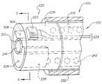
- Radiation delivery system 100includes a catheter system 200 , an intravascular ultrasound (IVUS) imaging system 300 , an afterloader system 400 , and a radiation source 500 .
- IVUSintravascular ultrasound
- Catheter system 200includes an elongate shaft 210 having a distal head 220 .
- Distal head 220includes a radiation shield 226 defining a window 224 and an ultrasonic transducer 222 , none of which are visible in FIG. 1, but will be described in greater detail with reference to FIGS. 2-6.
- a retractable sheath 230 having a distally disposed radiation shield 232may be slidably disposed about the elongate shaft 210 .
- a rotary drive 240may be connected to the proximal end of the elongate shaft 210 .
- the rotary drive 240rotates the distal head 220 relative to the elongate shaft 210 by means of a drive cable 242 extending through the shaft 210 , which is not visible in FIG. 1, but will be discussed in greater detail with reference to FIG. 2 .
- IVUS imaging system 300includes a signal generator/drive control 310 , a signal processor 320 , and a display/monitor 330 .
- the signal generator/drive control 310is operatively connected to the rotary drive 240 and the ultrasonic transducer in the distal head 220 by electrical connector/cable 340 .
- Electrical conductors 223extend through the catheter shaft 210 to connect the ultrasonic transducer 222 in the distal head 220 to the cable 340 .
- IVUS imaging system 300is generally conventional in design and use.
- An example of a suitable IVUS imaging system 300is commercially available from Boston Scientific Corporation.
- An optical coherence reflectometry (OCR) imaging systemmay be used in place of IVUS system 300 .
- Afterloader 400is also generally conventional except as described herein. Afterloader 400 is used to advance and retract the radiation source wire 500 into and out from the catheter system 200 .
- the radiation source 500may be fixed or removable. If a removable radiation source 500 is used, as in FIGS. 1, 4 , 5 and 6 , the radiation source 500 may comprise a conventional elongate wire 502 having a distally disposed ionizing radiation emitter 504 . If a fixed radiation source 500 is used, as in FIGS. 2 and 3, the wire 502 is not necessary and the radiation source 500 may simply comprise a conventional ionizing radiation emitter 504 disposed in the distal head 220 , with the afterloader 400 directly connected to the catheter 200 .
- Afterloader 400may be equipped with a means for measuring the radiation output of the radiation source 500 .
- the radiation output of the radiation emitter 504may be measured by running the radiation emitter 504 through a ring-shaped Geiger counter. This would allow for greater control of the radiation dose and permit automatic adjustment of the exposure time to compensate for any decay in the radiation emitter 504 . This feature would be particularly beneficial if the radiation emitter 504 utilized an isotope with a relatively short half life (e.g., Y90).
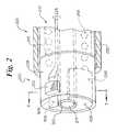
- FIG. 2illustrates a partially sectioned detailed side view of the distal end of the catheter 200
- FIG. 3illustrate a cross-sectional view taken along line 3 — 3 in FIG. 2
- the elongate shaft 210 of the catheter 200includes an inner tube 212 coaxially disposed in an outer tube 216 .
- the inner tube 212defines a guidewire/radiation source lumen 214 .
- An annular lumenis defined between the inner tube 212 and the outer tube 216 to accommodate the drive shaft 242 .
- the inner tube 212extends distally beyond the distal end of the outer tube 216 to serve as an axle for the rotatable distal head 220 .
- the inner tube 212 and the outer tube 216 of the elongate shaft 210may comprise any conventional shaft material such as a polymer or a reinforced polymer composite.
- the drive cable 242may comprise a multi-fillar metal cable or other conventional structure known to those skilled in the art of drive cables utilized in intravascular catheters.
- the distal end of the inner tube 212may extend beyond the distal end of the distal head 220 a sufficient distance to define a rapid exchange guidewire lumen (not shown).
- the inner tube 212may extend approximately 5 cm beyond the distal end of the head 220 with a guidewire access port defined through the wall of the inner tube 212 approximately 1 cm proximal of the distal end of the inner tube 212 .
- a removable stiffening mandrelmay be disposed in the lumen 214 of the inner tube 212 extending from the proximal end of the catheter shaft 210 to a point immediately proximal of the guidewire side port. With this arrangement, the catheter 200 may be operated in the rapid exchange mode or the over the wire mode.
- the distal head 220is rotatably mounted about the inner tube 212 and directly connected to the distal end of the drive shaft 242 .
- the proximal end of the drive shaft 242is operably connected to the rotary drive 240 which is controlled by the signal generator/drive control unit 310 .
- the drive shaft 242is freely disposed in the annular lumen defined between the inner tube 212 and the outer tube 216 such that rotation of the drive shaft 242 by rotary drive 240 causes the distal head 220 to rotate about the inner tube 212 relative to the shaft 210 .
- the distal head 220includes a transmitting/receiving ultrasonic transducer 222 which is operably connected to the imaging system 300 by way of electrical conductors 223 and cable 340 .
- the electrical conductors 223may either rotate with the drive cable 242 or remain stationary relative to the elongate shaft 210 . In either situation, rotary contacts (not shown) are necessary since the transducer 222 rotates relative to the electrical cable 340 . If the electrical conductors 223 rotate with the drive cable 242 , rotary contacts may be provided in the rotary drive unit 240 . If the electrical conductors 223 remain stationary relative to the drive cable 242 , rotary contacts may be provided at the interface between the proximal end of the distal head 220 and the distal end of the elongate shaft 210 .
- Distal head 220also includes a fixed radiation emitter 504 and a radiation shield 226 .
- Radiation emitter 504may comprise any suitable ionizing radiation material including beta and gamma radiation emitting isotopes.
- Radiation shield 226may similarly comprise any conventional shielding material that has sufficient density to attenuate radiation emitted from the radiation emitter 504 .
- Those skilled in the artwill recognize that many suitable isotopes may be used for radiation emitter 504 and many suitable attenuating materials may be used for radiation shield 226 .
- the radiation emitter 504comprises a C-shaped tubular solid element having a semi-circular cross-section.
- the exterior surface of the radiation emitter 504is coated with a suitable radiation attenuating material to form the radiation shield 226 .
- the proximal face, the distal face and the circumferential surfaceare coated with a radiation attenuating material.
- the radiation emitter 504has an uncoated surface 506 along the edge surfaces and the inside circumferential surface.
- the size of the windowmay be varied by altering the arc angle of the radiation emitter 504 and radiation shield 226 .
- the smaller the window 224the greater exposure time necessary to deliver a given dose.
- the larger the window 224the less exposure time required to deliver a given dose.
- the smaller the window 224the greater the accuracy of delivering the desired dose to a given target site.
- the size of the window 224may be varied depending on the desired level of accuracy balanced with the desired exposure time for a given dose.
- the ultrasonic transducer 222is located at a known position relative to the window 224 .
- the ultrasonic transducer 222is aligned with the window 224 .
- the transducer 222may be located 90° or 180° from the window 224 .
- the ultrasonic transducer 222may be located at any position relative to the window 224 as long as the relative position is known.
- the components of the distal head 220are held in place by a housing 228 which comprises a molded polymer or resin.
- the housing 228serves to maintain relative alignment of the components, namely the ultrasonic transducer 222 , the radiation shield 226 and the radiation emitter 504 .
- the housing 228comprises a material which does not attenuate radiation. Suitable low attenuation materials include polymers, low density metals and alloys, glass, and composites thereof.
- the entire housing 228may comprise a low attenuating material, or only the portions within the exposure range of the window 224 may comprise low attenuating material, while the remainder of the housing 228 comprises any suitable material that may attenuate radiation.
- the length of the radiation emitter 504 and the corresponding length of the radiation shield 226may be varied depending on the desired treatment length. For example, if relatively long segments of vasculature are to be treated, the radiation emitter 504 and radiation shield 226 may have a relatively long length on the order of 2 cm to 10 cm. Alternatively, a relatively short radiation emitter 504 and radiation shield 226 may be utilized to treat relatively short vascular segment. Also, a short radiation emitter 504 may be used to sequentially or continuously treat relatively long vascular segments. For example, a short radiation emitter 504 may be rotated and pulled back continuously, thereby tracing a spiral pattern on the inside surface of the artery to treat a long vascular segment in a single pass. A relatively short radiation emitter 504 and radiation shield 226 may, for example, have a length on the order of 0.1 cm to 2 cm.
- the catheter 200may optionally include a retractable sheath 230 coaxially and slidably disposed about the elongate shaft 210 .
- the retractable sheath 230includes a distal portion 232 which incorporates a radiation shielding material.
- the retractable sheath 230including the distal radiation shielding portion 232 , comprises a relatively flexible polymeric tube.
- the radiation shielding material on the distal end 232 of the retractable sheath 230may comprise any suitable material which attenuates radiation, such as a metallic coating on the polymer tube or a heavy metal powder loaded in the polymer tube wall.
- the catheter 200is inserted into the vascular system of the patient and navigated until the distal head 220 is disposed adjacent the treatment site. If a fixed radiation emitter 504 is utilized as in this particular embodiment, the retractable sheath 230 is positioned about the elongate shaft 210 such that the distal shielding portion 232 is disposed about the radiation emitter 504 in order to avoid unnecessary radiation exposure during navigation.
- the catheter 200is navigated through the vascular system over a guidewire extending through the lumen 214 of the inner tube 212 .
- the catheter 200may be operated in the over the wire mode or in the rapid exchange mode. Navigation of the catheter 200 may be assisted by conventional radiographic techniques and/or by utilizing the IVUS imaging system 300 .
- the IVUS imaging system 300may be activated to collect data indicative of the position of the distal head 220 relative to the surrounding tissue, the geometry of the surrounding tissue, and/or the characteristics of the surrounding tissue. This data may be used to determine the thickness of the stenotic material about the circumference of the treatment site and further to determine the relative position of the window 224 relative to the surrounding tissue. This data collection may be conducted with the distal head 220 in the static mode or in the dynamic mode. In the dynamic mode, the distal head 220 rotates at a velocity as dictated by the rotary drive 240 and controlled by the signal generator/drive control unit 310 .
- the distal head 220may be rotated at a relatively constant velocity to collect data correlating angular position of the transducer 222 and window 224 to the thickness of the stenotic material and the distance to the vascular wall. Utilizing this data, the desired treatment parameters may be selected by the physician. Generally speaking, in the areas having thicker stenotic material, radiation exposure time is relatively longer than the exposure time for thinner stenotic material. In addition, the greater the distance the target treatment site from the radiation emitter 504 and window 224 , the greater the exposure time. These variables (stenotic thickness and distance to vascular wall) may be utilized to determine the desired rotational velocity function. The velocity function may be preprogrammed into the signal generator/drive control unit 310 or manually programmed by the treating physician during the procedure.
- the retractable sheath 230may be retracted in the proximal direction until the distal end of the distal radiation shield 232 is located proximal of the radiation emitter 504 .
- the distal head 220may be rotated according to the predetermined velocity function for the desired treatment time.
- the retractable sheath 230may be advanced until the radiation shielding portion 232 covers the distal head 220 ) the entire catheter system 200 may be removed from the patient.
- the velocity function for the distal rotating head 220may be constant or variable.
- the velocity functionmay vary as a function of distance from the vascular wall and/or as a function of stenotic thickness.
- the velocity functionmay dictate that the rotatable head have a constant velocity within a single revolution but vary over a period of revolutions.
- the velocity functionmay dictate that the rotatable head 220 rotate at a velocity that varies within each revolution over a period of revolutions.
- the distal head 220may rotate at a relatively slow rate when the window 224 is aligned with relatively thick stenotic material or when the window 224 is relatively far from the vascular wall.
- the rotatable head 220may rotate at a relatively fast rate when the window 224 is aligned with relatively thin stenotic material or when the window 224 is relatively is close to the vascular wall.
- FIG. 4illustrates a detailed side view of an alternative embodiment of the distal end of the catheter 200
- FIG. 5illustrates a cross-sectional view taken along 5 — 5 in FIG. 4
- the embodiment of FIGS. 4 and 5is the same in design and use as the embodiment of FIGS. 2 and 3.
- the primary difference between the embodiment of FIGS. 2 and 3 and the embodiment of FIGS. 4 and 5is that the radiation source 500 is removable.
- the embodiment of FIGS. 2 and 3provided a fixed radiation source 500 comprising a radiation emitter 504 disposed in the distal head 220 .
- catheter 200may be utilized for imaging purposes independent of whether radiation treatment is to be administered.
- the elongate shaft 210includes an outer tube 216 and an inner tube 212 .
- the inner tube 212extends beyond the distal end of the outer tube 216 to the distal end of the distal head 220 .
- the radiation shield 226is disposed about the portion of the inner tube 212 extending through the distal head 220 .
- the radiation shield 226comprises a tubular structure made of radiation attenuating material having a cut out portion defining a window 224 .
- the radiation shield 226rotates with the distal head 220 about the inner tube 212 .
- the catheter 200 of this embodimentmay be intravascularly navigated with the radiation source 500 contained within the afterloader 400 .
- the guide wireis withdrawn from the lumen 214 to permit insertion of the radiation source 500 .
- the afterloader 400may be used to advance the radiation source 500 until the radiation emitter 504 is disposed within the distal head 220 .
- the distal head 220may then be rotated as discussed previously to selectively expose portions of the treatment site to radiation through window 224 .
- the afterloader 400may be activated to retract the radiation source therein, and the catheter system 200 may be withdrawn.
- FIG. 6illustrates a cross-sectional view of an alternative embodiment of the distal end of the catheter 200 illustrated in FIG. 5 .
- FIG. 6illustrates an alternative arrangement of the components of the distal head 220 used in the embodiment illustrated in FIGS. 4 and 5. Except as described herein, the embodiment of FIG. 6 is the same in design and use as the embodiment of FIGS. 4 and 5.
- the inner tube 212terminates adjacent the distal end of the outer tube 216 .
- the distal head 220includes a radiation shield 226 which functions as described previously, but also serves to define the lumen 214 within the distal head 220 . With this arrangement, the distal head 220 does not rely on the inner tube 212 to serve as an axle for rotation. Rather, the distal head 220 is supported by the drive cable 242 and the radiation source 500 inserted therein.
- Radiation delivery system 100includes a catheter system 200 including a rotatable distal head 220 .
- a fixed or removable radiation source 500is disposed in or adjacent to the distal head 220 .
- the distal head 220includes a radiation shield 226 having a window 224 and an ultrasonic transducer 222 at a known position relative to the window 224 .
- the ultrasonic transducer 222provides data indictitive of the relative position of the distal head 220 and the geometry and characteristics of the surrounding tissue, which may be utilized to determine the appropriate treatment parameters, including a velocity function for the rotatable distal head 220 .
- Rotatable head 220may be rotated according to the velocity function which varies according to the distance of the window 224 and radiation emitter 504 from the vascular wall and/or the relative thickness of the stenotic material.
Landscapes
- Health & Medical Sciences (AREA)
- Engineering & Computer Science (AREA)
- Biomedical Technology (AREA)
- Pathology (AREA)
- Nuclear Medicine, Radiotherapy & Molecular Imaging (AREA)
- Radiology & Medical Imaging (AREA)
- Life Sciences & Earth Sciences (AREA)
- Animal Behavior & Ethology (AREA)
- General Health & Medical Sciences (AREA)
- Public Health (AREA)
- Veterinary Medicine (AREA)
- Ultra Sonic Daignosis Equipment (AREA)
Abstract
Description
The present application is related to U.S. patent application Ser. No. 09/672,569, entitled COMPUTER CONTROLLED RADIATION DELIVERY SYSTEM, filed on even date herewith, which is herein incorporated by reference.
The present invention generally relates to intravascular medical devices. More specifically, the present invention relates to medical devices suitable for intravascular ionizing radiation therapy.
Intravascular ionizing radiation therapy is being used increasingly to treat vascular disease. For example, the administration of ionizing radiation has been proposed as both a primary and a secondary therapy for treatment of vascular stenosis (a vascular restriction or narrowing). Clinical studies show that ionizing radiation may be used to inhibit or prevent restenosis after angioplasty.
Vascular restrictions often vary in shape and size, depending on the extent and nature of the disease, in addition to the size and type of vessel affected. In cross-section, the stenotic tissues forming the vascular restrictions often vary in thickness. Such vascular restrictions with varying thickness may require different amounts of radiation exposure, depending on the thickness of the stenotic material and the relative position of the radiation source.
To address this issue, U.S. Pat. No. 6,033,357 to Ciezki et al. propose the use of a radiation delivery device having a window defined by an attenuator for directing radiation emitted from a radiation source. The attenuator alters the radiation exposure pattern such that compensation may be made for any irregular shape of the stenosis or eccentric positioning of the radiation source. In use, a first intravascular ultrasound (IVUS) catheter is inserted into the vascular system to determine the configuration of the vessel wall and the shape of the stenosis. Based on this information, the configuration of the attenuator section is selected to deliver the desired radiation dose profile. The first IVUS catheter is then withdrawn and the radiation delivery system is inserted into the vascular system. A second IVUS catheter is inserted into the radiation delivery system to orient the attenuator such that the window is adjacent the area to receive the most amount of radiation. The second IVUS catheter is then removed from the delivery system and a radioactive wire is inserted into the delivery system until the radioactive portion is positioned within the treatment area. After sufficient time is allowed to emit the proposed dosage, the radiation source is removed from the delivery system.
The Ciezki et al. device inherently relies on maintaining the desired position of the delivery system between withdrawal of the second IVUS catheter and insertion of the radioactive wire. Any difference in position between these two steps will inevitably result in certain portions of the treatment area receiving more or less radiation than intended. Furthermore, if it is necessary to treat other areas of the vasculature, the individual imaging and delivery steps must be repeated in sequence for each area of the vasculature to be treated. Such numerous steps (repositioning, inserting, removing, etc.) complicate the procedure and consume significant operating room/lab time. In addition, the Ciezki et al. device requires many different attenuators to be stocked in a variety of different sizes, shapes, densities and configurations to address different clinical circumstances. Accordingly, it is desirable to provide a radiation delivery system utilizing IVUS technology that is not susceptible to procedural complexities as with the Ciezki et al. system.
The present invention addresses these shortcomings by providing a radiation delivery system that fully integrates intravascular ultrasound (IVUS) technology. The radiation system includes a catheter having a distal head. A fixed or removable radiation source is disposed in or adjacent to the distal head. The distal head includes a radiation shield having a window and an ultrasonic transducer. The ultrasonic transducer facilitates placement of the radiation shield window, such that only a portion of the treatment site is exposed to radiation.
Specifically, the ultrasonic transducer provides a signal indicative of relative position, tissue geometry and/or tissue characteristics which may be utilized to determine the appropriate placement of the radiation shield window. Placement of the radiation shield window affects the dose administered to different portions of the treatment site. Thus, the dose may be varied to target different areas of the treatment site with the desired radiation dose.
The radiation delivery system may include a drive means coupled to the distal head to facilitate rotation thereof. The distal head may rotate at a constant velocity or at a variable velocity. For example, the distal head may rotate at a velocity which varies as a function of distance from the vascular wall and/or as a function of stenotic thickness.
The radiation delivery system may include a retractable sheath having a distally disposed radiation shield positioned over the radiation source. The retractable sheath may be used to shield radiation during intravascular navigating and positioning of the delivery system to avoid undesired radiation exposure.
The present invention also provides a method of treating a vascular site with ionizing radiation utilizing a radiation system substantially as described above. The catheter is first introduced into the vascular system of the patient and advanced until the distal head is disposed adjacent the treatment site. The ultrasonic transducer is then activated to generate data indicative of relative position, tissue geometry and/or tissue characteristics at the treatment site. The radiation shield window is then moved as a function of the data to selectively expose the treatment site to ionizing radiation. If a rotating shield is used, the velocity of rotation may be varied as a function of the data, (e.g., distance from the vascular wall and/or stenotic thickness).
FIG. 1 is a schematic plan view of the intravascular radiation delivery system of the present invention;
FIG. 2 is a partially sectioned detailed side view of the distal end of the catheter of the system illustrated in FIG. 1;
FIG. 3 is a cross-sectional view taken alongline 3—3 in FIG. 2;
FIG. 4 is a detailed side view of an alternative embodiment of the distal end of the catheter of the system illustrated in FIG. 1;
FIG. 5 is a cross-sectional view taken alongline 5—5 in FIG. 4; and
FIG. 6 is a cross-sectional view of an alternative embodiment of the distal end illustrated in FIG.5.
The following detailed description should be read with reference to the drawings in which similar elements in different drawings are numbered the same. The drawings, which are not necessarily to scale, depict illustrative embodiments and are not intended to limit the scope of the invention.
Refer now to FIG. 1 which schematically illustratesradiation delivery system 100 of the present invention.Radiation delivery system 100 includes acatheter system 200, an intravascular ultrasound (IVUS)imaging system 300, anafterloader system 400, and aradiation source 500.
IVUSimaging system 300 includes a signal generator/drive control 310, asignal processor 320, and a display/monitor 330. The signal generator/drive control 310 is operatively connected to therotary drive 240 and the ultrasonic transducer in thedistal head 220 by electrical connector/cable 340.Electrical conductors 223, not visible in FIG. 1, extend through thecatheter shaft 210 to connect theultrasonic transducer 222 in thedistal head 220 to thecable 340. Except as described herein,IVUS imaging system 300 is generally conventional in design and use. An example of a suitableIVUS imaging system 300 is commercially available from Boston Scientific Corporation. An optical coherence reflectometry (OCR) imaging system may be used in place ofIVUS system 300.
Refer now to FIG. 2 which illustrates a partially sectioned detailed side view of the distal end of thecatheter 200, and FIG. 3 which illustrate a cross-sectional view taken alongline 3—3 in FIG.2. Theelongate shaft 210 of thecatheter 200 includes aninner tube 212 coaxially disposed in anouter tube 216. Theinner tube 212 defines a guidewire/radiation source lumen 214. An annular lumen is defined between theinner tube 212 and theouter tube 216 to accommodate thedrive shaft 242. Theinner tube 212 extends distally beyond the distal end of theouter tube 216 to serve as an axle for the rotatabledistal head 220.
Theinner tube 212 and theouter tube 216 of theelongate shaft 210 may comprise any conventional shaft material such as a polymer or a reinforced polymer composite. Thedrive cable 242 may comprise a multi-fillar metal cable or other conventional structure known to those skilled in the art of drive cables utilized in intravascular catheters.
Optionally, the distal end of theinner tube 212 may extend beyond the distal end of the distal head220 a sufficient distance to define a rapid exchange guidewire lumen (not shown). Theinner tube 212 may extend approximately 5 cm beyond the distal end of thehead 220 with a guidewire access port defined through the wall of theinner tube 212 approximately 1 cm proximal of the distal end of theinner tube 212. A removable stiffening mandrel may be disposed in thelumen 214 of theinner tube 212 extending from the proximal end of thecatheter shaft 210 to a point immediately proximal of the guidewire side port. With this arrangement, thecatheter 200 may be operated in the rapid exchange mode or the over the wire mode.
Thedistal head 220 is rotatably mounted about theinner tube 212 and directly connected to the distal end of thedrive shaft 242. The proximal end of thedrive shaft 242 is operably connected to therotary drive 240 which is controlled by the signal generator/drive control unit 310. Thedrive shaft 242 is freely disposed in the annular lumen defined between theinner tube 212 and theouter tube 216 such that rotation of thedrive shaft 242 byrotary drive 240 causes thedistal head 220 to rotate about theinner tube 212 relative to theshaft 210.
Thedistal head 220 includes a transmitting/receivingultrasonic transducer 222 which is operably connected to theimaging system 300 by way ofelectrical conductors 223 andcable 340. Theelectrical conductors 223 may either rotate with thedrive cable 242 or remain stationary relative to theelongate shaft 210. In either situation, rotary contacts (not shown) are necessary since thetransducer 222 rotates relative to theelectrical cable 340. If theelectrical conductors 223 rotate with thedrive cable 242, rotary contacts may be provided in therotary drive unit 240. If theelectrical conductors 223 remain stationary relative to thedrive cable 242, rotary contacts may be provided at the interface between the proximal end of thedistal head 220 and the distal end of theelongate shaft 210.
In this particular embodiment, theradiation emitter 504 comprises a C-shaped tubular solid element having a semi-circular cross-section. The exterior surface of theradiation emitter 504 is coated with a suitable radiation attenuating material to form theradiation shield 226. Preferably, the proximal face, the distal face and the circumferential surface are coated with a radiation attenuating material. Thus, theradiation emitter 504 has anuncoated surface 506 along the edge surfaces and the inside circumferential surface. By providing aradiation shield 226 andradiation emitter 504 in this configuration, awindow 224 is defined as best seen in FIG.3.Window 224 defines the size and geometry of the lateral radiation exposure. The size of the window may be varied by altering the arc angle of theradiation emitter 504 andradiation shield 226. Generally, the smaller thewindow 224, the greater exposure time necessary to deliver a given dose. Similarly, the larger thewindow 224 the less exposure time required to deliver a given dose. In addition, the smaller thewindow 224, the greater the accuracy of delivering the desired dose to a given target site. Thus, the size of thewindow 224 may be varied depending on the desired level of accuracy balanced with the desired exposure time for a given dose.
Theultrasonic transducer 222 is located at a known position relative to thewindow 224. Preferably, theultrasonic transducer 222 is aligned with thewindow 224. Alternatively, to avoid potential adverse effects of radiation exposure, thetransducer 222 may be located 90° or 180° from thewindow 224. To the extent thattransducer 222 comprises a material that attenuates radiation, it may be desirable to locate thetransducer 222 outside the exposure range of thewindow 224. However, theultrasonic transducer 222 may be located at any position relative to thewindow 224 as long as the relative position is known.
The components of thedistal head 220 are held in place by ahousing 228 which comprises a molded polymer or resin. Thehousing 228 serves to maintain relative alignment of the components, namely theultrasonic transducer 222, theradiation shield 226 and theradiation emitter 504. Preferably, thehousing 228 comprises a material which does not attenuate radiation. Suitable low attenuation materials include polymers, low density metals and alloys, glass, and composites thereof. Theentire housing 228 may comprise a low attenuating material, or only the portions within the exposure range of thewindow 224 may comprise low attenuating material, while the remainder of thehousing 228 comprises any suitable material that may attenuate radiation.
The length of theradiation emitter 504 and the corresponding length of theradiation shield 226 may be varied depending on the desired treatment length. For example, if relatively long segments of vasculature are to be treated, theradiation emitter 504 andradiation shield 226 may have a relatively long length on the order of 2 cm to 10 cm. Alternatively, a relativelyshort radiation emitter 504 andradiation shield 226 may be utilized to treat relatively short vascular segment. Also, ashort radiation emitter 504 may be used to sequentially or continuously treat relatively long vascular segments. For example, ashort radiation emitter 504 may be rotated and pulled back continuously, thereby tracing a spiral pattern on the inside surface of the artery to treat a long vascular segment in a single pass. A relativelyshort radiation emitter 504 andradiation shield 226 may, for example, have a length on the order of 0.1 cm to 2 cm.
Thecatheter 200 may optionally include aretractable sheath 230 coaxially and slidably disposed about theelongate shaft 210. Theretractable sheath 230 includes adistal portion 232 which incorporates a radiation shielding material. Preferably, theretractable sheath 230, including the distalradiation shielding portion 232, comprises a relatively flexible polymeric tube. The radiation shielding material on thedistal end 232 of theretractable sheath 230 may comprise any suitable material which attenuates radiation, such as a metallic coating on the polymer tube or a heavy metal powder loaded in the polymer tube wall.
In use, thecatheter 200 is inserted into the vascular system of the patient and navigated until thedistal head 220 is disposed adjacent the treatment site. If a fixedradiation emitter 504 is utilized as in this particular embodiment, theretractable sheath 230 is positioned about theelongate shaft 210 such that thedistal shielding portion 232 is disposed about theradiation emitter 504 in order to avoid unnecessary radiation exposure during navigation. Thecatheter 200 is navigated through the vascular system over a guidewire extending through thelumen 214 of theinner tube 212. As mentioned previously, thecatheter 200 may be operated in the over the wire mode or in the rapid exchange mode. Navigation of thecatheter 200 may be assisted by conventional radiographic techniques and/or by utilizing theIVUS imaging system 300.
Once in the desired position, theIVUS imaging system 300 may be activated to collect data indicative of the position of thedistal head 220 relative to the surrounding tissue, the geometry of the surrounding tissue, and/or the characteristics of the surrounding tissue. This data may be used to determine the thickness of the stenotic material about the circumference of the treatment site and further to determine the relative position of thewindow 224 relative to the surrounding tissue. This data collection may be conducted with thedistal head 220 in the static mode or in the dynamic mode. In the dynamic mode, thedistal head 220 rotates at a velocity as dictated by therotary drive 240 and controlled by the signal generator/drive control unit 310.
For imaging purposes, thedistal head 220 may be rotated at a relatively constant velocity to collect data correlating angular position of thetransducer 222 andwindow 224 to the thickness of the stenotic material and the distance to the vascular wall. Utilizing this data, the desired treatment parameters may be selected by the physician. Generally speaking, in the areas having thicker stenotic material, radiation exposure time is relatively longer than the exposure time for thinner stenotic material. In addition, the greater the distance the target treatment site from theradiation emitter 504 andwindow 224, the greater the exposure time. These variables (stenotic thickness and distance to vascular wall) may be utilized to determine the desired rotational velocity function. The velocity function may be preprogrammed into the signal generator/drive control unit 310 or manually programmed by the treating physician during the procedure.
Once the desired rotational velocity function is determined, theretractable sheath 230 may be retracted in the proximal direction until the distal end of thedistal radiation shield 232 is located proximal of theradiation emitter 504. After retracting thesheath 230 to expose theradiation emitter 504, thedistal head 220 may be rotated according to the predetermined velocity function for the desired treatment time. After the desired treatment time has expired, (although not necessary, theretractable sheath 230 may be advanced until theradiation shielding portion 232 covers the distal head220) theentire catheter system 200 may be removed from the patient.
The velocity function for the distalrotating head 220 may be constant or variable. For example, the velocity function may vary as a function of distance from the vascular wall and/or as a function of stenotic thickness. The velocity function may dictate that the rotatable head have a constant velocity within a single revolution but vary over a period of revolutions. Alternatively, the velocity function may dictate that therotatable head 220 rotate at a velocity that varies within each revolution over a period of revolutions. For example, thedistal head 220 may rotate at a relatively slow rate when thewindow 224 is aligned with relatively thick stenotic material or when thewindow 224 is relatively far from the vascular wall. In addition, therotatable head 220 may rotate at a relatively fast rate when thewindow 224 is aligned with relatively thin stenotic material or when thewindow 224 is relatively is close to the vascular wall.
Refer down to FIG. 4, which illustrates a detailed side view of an alternative embodiment of the distal end of thecatheter 200, and FIG. 5 which illustrates a cross-sectional view taken along5—5 in FIG.4. Except as described herein, the embodiment of FIGS. 4 and 5 is the same in design and use as the embodiment of FIGS. 2 and 3. The primary difference between the embodiment of FIGS. 2 and 3 and the embodiment of FIGS. 4 and 5 is that theradiation source 500 is removable. Specifically, the embodiment of FIGS. 2 and 3 provided a fixedradiation source 500 comprising aradiation emitter 504 disposed in thedistal head 220. By contrast, theradiation source 500 of the embodiment illustrated in FIGS. 4 and 5 is a removable source requiring anelongate delivery wire 502 and anafterloader 400 as discussed previously. One advantage of this embodiment relative to the embodiment, discussed with reference to FIGS. 2 and 3 is that thecatheter 200 may be utilized for imaging purposes independent of whether radiation treatment is to be administered.
As seen in FIGS. 4 and 5, theelongate shaft 210 includes anouter tube 216 and aninner tube 212. As in the previously discussed embodiment, theinner tube 212 extends beyond the distal end of theouter tube 216 to the distal end of thedistal head 220. However, in this particular embodiment, theradiation shield 226 is disposed about the portion of theinner tube 212 extending through thedistal head 220. Theradiation shield 226 comprises a tubular structure made of radiation attenuating material having a cut out portion defining awindow 224. Theradiation shield 226 rotates with thedistal head 220 about theinner tube 212. With this arrangement, when theradiation emitter 504 is disposed within thelumen 214 adjacent to thewindow 224, radiation is shielded around the periphery of theradiation emitter 504 by theshield 226, except in thewindow portion 224.
This embodiment does not require the use of aretractable shield 230 as discussed with reference to FIGS. 2 and 3. Rather, thecatheter 200 of this embodiment may be intravascularly navigated with theradiation source 500 contained within theafterloader 400. After thecatheter 200 is navigated to the desired treatment site, the guide wire is withdrawn from thelumen 214 to permit insertion of theradiation source 500. With thedistal head 220 is in the desired position and the velocity function and other treatment parameters programmed, theafterloader 400 may be used to advance theradiation source 500 until theradiation emitter 504 is disposed within thedistal head 220. Thedistal head 220 may then be rotated as discussed previously to selectively expose portions of the treatment site to radiation throughwindow 224. After the desired treatment time, theafterloader 400 may be activated to retract the radiation source therein, and thecatheter system 200 may be withdrawn.
Refer now to FIG. 6 which illustrates a cross-sectional view of an alternative embodiment of the distal end of thecatheter 200 illustrated in FIG.5. Specifically, FIG. 6 illustrates an alternative arrangement of the components of thedistal head 220 used in the embodiment illustrated in FIGS. 4 and 5. Except as described herein, the embodiment of FIG. 6 is the same in design and use as the embodiment of FIGS. 4 and 5.
In the embodiment illustrated in FIG. 6 theinner tube 212 terminates adjacent the distal end of theouter tube 216. Thedistal head 220 includes aradiation shield 226 which functions as described previously, but also serves to define thelumen 214 within thedistal head 220. With this arrangement, thedistal head 220 does not rely on theinner tube 212 to serve as an axle for rotation. Rather, thedistal head 220 is supported by thedrive cable 242 and theradiation source 500 inserted therein.
From the foregoing, it should be apparent that the present invention provides aradiation delivery system 100 that fully integrates anIVUS system 300.Radiation delivery system 100 includes acatheter system 200 including a rotatabledistal head 220. A fixed orremovable radiation source 500 is disposed in or adjacent to thedistal head 220. Thedistal head 220 includes aradiation shield 226 having awindow 224 and anultrasonic transducer 222 at a known position relative to thewindow 224. Theultrasonic transducer 222 provides data indictitive of the relative position of thedistal head 220 and the geometry and characteristics of the surrounding tissue, which may be utilized to determine the appropriate treatment parameters, including a velocity function for the rotatabledistal head 220.Rotatable head 220 may be rotated according to the velocity function which varies according to the distance of thewindow 224 andradiation emitter 504 from the vascular wall and/or the relative thickness of the stenotic material.
Those skilled in the art will recognize that the present invention may be manifested in a variety of forms other than the specific embodiments described and contemplated herein. Accordingly, departures in form and detail may be made without departing from the scope and spirit of the present invention as described in the appended claims.
Claims (35)
1. An intravascular radiation system for the treatment of a vascular site by ionizing radiation, the radiation system comprising:
an elongate catheter having a proximal end and a distal end;
a head disposed on the distal end of the catheter, the head including a radiation shield having a window and an ultrasonic transducer; and
a radiation source disposed adjacent the radiation shield.
2. An intravascular radiation catheter as inclaim 1 , wherein the radiation source is fixed relative to the catheter.
3. An intravascular radiation catheter as inclaim 1 , wherein the radiation source is movable relative to the catheter.
4. An intravascular radiation catheter as inclaim 1 , wherein the radiation shield is fixed relative to the transducer.
5. An intravascular radiation catheter as inclaim 4 , wherein the head is rotatable relative to the shaft.
6. An intravascular radiation catheter as inclaim 5 , further comprising a drive means coupled to the head.
7. An intravascular radiation catheter as inclaim 5 , wherein the head rotates at a constant velocity.
8. An intravascular radiation catheter as inclaim 5 , wherein the head rotates at a variable velocity.
9. An intravascular radiation catheter as inclaim 8 , wherein the vascular site defines a vascular wall and wherein the head rotates at a velocity which varies as a function of distance from the vascular wall.
10. An intravascular radiation catheter as inclaim 8 , wherein the vascular site defines a stenotic thickness and wherein the head rotates at a velocity which varies as a function of stenotic thickness.
11. An intravascular radiation catheter as inclaim 8 , wherein the head rotates at a velocity which is constant within a revolution, but varies over a period of revolutions.
12. An intravascular radiation catheter as inclaim 8 , wherein the head rotates at a velocity which varies within a revolution over a period of revolutions.
13. An intravascular radiation catheter as inclaim 4 , wherein the ultrasonic transducer is aligned with the window of the radiation shield.
14. An intravascular radiation catheter as inclaim 4 , wherein the ultrasonic transducer is disposed at an angular position relative to the window of the radiation shield.
15. An intravascular radiation catheter as inclaim 14 , wherein the angular position is 90 degrees.
16. An intravascular radiation catheter as inclaim 14 , wherein the angular position is 180 degrees.
17. An intravascular radiation catheter as inclaim 4 , further comprising a retractable sheath having a distally disposed radiation shield positioned over the radiation source.
18. An intravascular radiation catheter as inclaim 4 , wherein the catheter shaft includes a guidewire lumen.
19. An intravascular radiation catheter as inclaim 18 , wherein the guidewire lumen has a proximal end disposed distally of the head.
20. An intravascular radiation catheter as inclaim 4 , wherein the radiation shield is semi-circular in cross-section.
21. An intravascular radiation catheter as inclaim 20 , wherein the open portion of the semi-circle is the window.
22. An intravascular radiation catheter as inclaim 21 , wherein the radiation shield is tubular.
23. An intravascular radiation catheter as inclaim 22 , wherein the radiation source is disposed in the radiation shield.
24. An intravascular radiation catheter as inclaim 4 , wherein the radiation source is semi-circular in cross-section.
25. An intravascular radiation catheter as inclaim 24 , wherein the radiation source is tubular.
26. An intravascular radiation catheter as inclaim 25 , wherein the radiation shield covers the outer surface of the radiation source.
27. An intravascular radiation catheter as inclaim 4 , wherein the radiation source comprises an elongate shaft having a distally disposed radiation emitter.
28. An intravascular radiation catheter as inclaim 27 , wherein the catheter shaft includes a source lumen and wherein the radiation source is disposed therein.
29. A method of treating a vascular site in the vascular system of a patient by ionizing radiation, the method comprising the steps of:
providing an intravascular radiation system comprising an elongate catheter shaft having a proximal end and a distal end, a distal head disposed on the distal end of the shaft, the head including a radiation shield having a window and an ultrasonic transducer, and
a radiation source disposed adjacent the radiation shield;
inserting the catheter shaft into the vascular system of the patient;
advancing the catheter shaft until the head is disposed adjacent the treatment site;
activating the ultrasonic transducer to generate data indicative of the nature of the vascular site and/or the position of the head relative to the vascular site; and
moving the shield as a function of the data to selectively expose the treatment site to ionizing radiation emitted from the radiation source.
30. A method of treating a vascular site as inclaim 29 , wherein the head is rotatable and wherein the step of moving the shield comprises rotating the shield.
31. A method of treating a vascular site as inclaim 30 , wherein the head is rotated at a constant velocity.
32. A method of treating a vascular site as inclaim 30 , wherein the head is rotated at a variable velocity.
33. An intravascular radiation catheter as inclaim 32 , wherein the velocity varies as a function of distance from the vascular wall.
34. An intravascular radiation catheter as inclaim 32 , wherein the velocity varies as a function of stenotic thickness.
35. A method of treating a vascular site as inclaim 29 , wherein the radiation system includes a retractable sheath having a distally disposed radiation shield initially positioned over the radiation source, the method further comprising the step of moving the sheath to expose the radiation source.
Priority Applications (1)
| Application Number | Priority Date | Filing Date | Title |
|---|---|---|---|
| US09/672,423US6416492B1 (en) | 2000-09-28 | 2000-09-28 | Radiation delivery system utilizing intravascular ultrasound |
Applications Claiming Priority (1)
| Application Number | Priority Date | Filing Date | Title |
|---|---|---|---|
| US09/672,423US6416492B1 (en) | 2000-09-28 | 2000-09-28 | Radiation delivery system utilizing intravascular ultrasound |
Publications (1)
| Publication Number | Publication Date |
|---|---|
| US6416492B1true US6416492B1 (en) | 2002-07-09 |
Family
ID=24698481
Family Applications (1)
| Application Number | Title | Priority Date | Filing Date |
|---|---|---|---|
| US09/672,423Expired - Fee RelatedUS6416492B1 (en) | 2000-09-28 | 2000-09-28 | Radiation delivery system utilizing intravascular ultrasound |
Country Status (1)
| Country | Link |
|---|---|
| US (1) | US6416492B1 (en) |
Cited By (37)
| Publication number | Priority date | Publication date | Assignee | Title |
|---|---|---|---|---|
| US20020174721A1 (en)* | 2001-03-30 | 2002-11-28 | Malte Gross | Method and device for detecting stenoses in a tubular line system |
| US20030135102A1 (en)* | 2000-05-18 | 2003-07-17 | Burdette Everette C. | Method and system for registration and guidance of intravascular treatment |
| US20030229282A1 (en)* | 1997-11-24 | 2003-12-11 | Burdette Everette C. | Real time brachytherapy spatial registration and visualization system |
| US20040022438A1 (en)* | 2002-08-02 | 2004-02-05 | Hibbard Lyndon S. | Method and apparatus for image segmentation using Jensen-Shannon divergence and Jensen-Renyi divergence |
| US20050113685A1 (en)* | 2003-11-21 | 2005-05-26 | Michael Maschke | Medical system for examination or treatment |
| US20050182316A1 (en)* | 2002-08-29 | 2005-08-18 | Burdette Everette C. | Method and system for localizing a medical tool |
| WO2006014701A2 (en) | 2004-07-20 | 2006-02-09 | Board Of Regents, The University Of Texas System | Adaptive intracavitary brachytherapy applicator |
| US20060201604A1 (en)* | 2002-02-28 | 2006-09-14 | Wilson Richard R | Ultrasound catheter with embedded conductors |
| US20060205992A1 (en)* | 2002-11-06 | 2006-09-14 | Senorx, Inc. | Temporary catheter for biopsy site tissue fixation |
| US7171255B2 (en) | 1995-07-26 | 2007-01-30 | Computerized Medical Systems, Inc. | Virtual reality 3D visualization for surgical procedures |
| US20070027352A1 (en)* | 2004-07-20 | 2007-02-01 | Board Of Regents, The University Of Texas System | Adaptive intracavitary brachytherapy applicator |
| US20070060893A1 (en)* | 2001-11-28 | 2007-03-15 | Mahurkar Sakharam D | Retractable needle single use safety syringe |
| WO2007060050A1 (en)* | 2005-11-24 | 2007-05-31 | Siemens Aktiengesellschaft | Device for x-ray brachytherapy, and method for positioning a probe introduced into a body for x-ray brachytherapy |
| US20070129592A1 (en)* | 2005-11-18 | 2007-06-07 | Senorx, Inc. | Treatment of a body cavity |
| US20070167667A1 (en)* | 2005-11-18 | 2007-07-19 | Senorx, Inc. | Methods for asymmetrical irradiation of a body cavity |
| US20070191667A1 (en)* | 2005-11-18 | 2007-08-16 | Senorx, Inc. | Methods for tissue irradiation with shielding |
| US20080027265A1 (en)* | 2006-07-25 | 2008-01-31 | Ams Research Corporation | Shielded High Dose Radiation Catheters |
| US20080064915A1 (en)* | 2002-11-06 | 2008-03-13 | Senorx, Inc. | Vacuum device and method for treating tissue adjacent a body cavity |
| US20080221506A1 (en)* | 2001-12-03 | 2008-09-11 | Rodriguez Oscar E | Small vessel ultrasound cathter |
| US20080228025A1 (en)* | 2007-03-12 | 2008-09-18 | Senorx, Inc. | Radiation catheter with multilayered balloon |
| US20080228023A1 (en)* | 2007-03-15 | 2008-09-18 | Senorx, Inc. | Soft body catheter with low friction lumen |
| US20080228024A1 (en)* | 2007-03-15 | 2008-09-18 | Senorx, Inc. | Soft body catheter with low friction lumen |
| US7438685B2 (en) | 2001-11-05 | 2008-10-21 | Computerized Medical Systems, Inc. | Apparatus and method for registration, guidance and targeting of external beam radiation therapy |
| US20090188098A1 (en)* | 2008-01-24 | 2009-07-30 | Senorx, Inc. | Multimen brachytherapy balloon catheter |
| US20090209805A1 (en)* | 2005-11-18 | 2009-08-20 | Senorx, Inc. | Tissue irradiation |
| US20100010287A1 (en)* | 2008-07-09 | 2010-01-14 | Senorx, Inc. | Brachytherapy device with one or more toroidal balloons |
| US20120053512A1 (en)* | 2010-09-01 | 2012-03-01 | Becton, Dickinson And Company | Uv-c antimicrobial device for intravenous therapy |
| WO2012142223A1 (en)* | 2011-04-13 | 2012-10-18 | St. Jude Medical, Inc. | Acoustic transducer for pulse-echo monitoring and control of thermally ablative lesioning in layered and nonlayered tissues, catheter contact monitoring, tissue thickness measurement and pre-pop warning |
| DE102013001989A1 (en)* | 2013-02-06 | 2014-08-07 | Michael Friebe | Hand-held hybrid diagnostic and low energy irradiation system used for treatment of benign and malignant tumors, has low-energy radiation source that is provided with diagnostic imaging system integrated with gamma camera |
| US9248311B2 (en) | 2009-02-11 | 2016-02-02 | Hologic, Inc. | System and method for modifying a flexibility of a brachythereapy catheter |
| US9579524B2 (en) | 2009-02-11 | 2017-02-28 | Hologic, Inc. | Flexible multi-lumen brachytherapy device |
| US9623260B2 (en) | 2004-11-05 | 2017-04-18 | Theragenics Corporation | Expandable brachytherapy device |
| US10022557B2 (en) | 2010-09-30 | 2018-07-17 | Hologic, Inc. | Using a guided member to facilitate brachytherapy device swap |
| US10207126B2 (en) | 2009-05-11 | 2019-02-19 | Cytyc Corporation | Lumen visualization and identification system for multi-lumen balloon catheter |
| US10342992B2 (en) | 2011-01-06 | 2019-07-09 | Hologic, Inc. | Orienting a brachytherapy applicator |
| US20220184416A1 (en)* | 2019-03-19 | 2022-06-16 | Universityof Iowa Research Foundation | Rotating shield brachytherapy apparatus and method |
| US11617901B2 (en)* | 2018-05-02 | 2023-04-04 | University Of Virginia Patent Foundation | Application of radiation using imaging guidance |
Citations (93)
| Publication number | Priority date | Publication date | Assignee | Title |
|---|---|---|---|---|
| US5010886A (en) | 1989-08-18 | 1991-04-30 | Intertherapy, Inc. | Medical probe assembly having combined ultrasonic imaging and laser ablation capabilities |
| US5125137A (en) | 1990-09-06 | 1992-06-30 | Cardiometrics, Inc. | Method for providing a miniature ultrasound high efficiency transducer assembly |
| US5131397A (en) | 1990-09-07 | 1992-07-21 | Boston Scientific Corp. | Imaging system for producing ultrasonic images and insonifier for such systems |
| US5199939A (en) | 1990-02-23 | 1993-04-06 | Dake Michael D | Radioactive catheter |
| US5213561A (en) | 1990-09-06 | 1993-05-25 | Weinstein Joseph S | Method and devices for preventing restenosis after angioplasty |
| US5243988A (en) | 1991-03-13 | 1993-09-14 | Scimed Life Systems, Inc. | Intravascular imaging apparatus and methods for use and manufacture |
| US5269291A (en) | 1990-12-10 | 1993-12-14 | Coraje, Inc. | Miniature ultrasonic transducer for plaque ablation |
| US5302168A (en) | 1991-09-05 | 1994-04-12 | Hess Robert L | Method and apparatus for restenosis treatment |
| US5307816A (en) | 1991-08-21 | 1994-05-03 | Kabushiki Kaisha Toshiba | Thrombus resolving treatment apparatus |
| US5318014A (en) | 1992-09-14 | 1994-06-07 | Coraje, Inc. | Ultrasonic ablation/dissolution transducer |
| US5329194A (en) | 1992-11-23 | 1994-07-12 | Capistrano Labs, Inc. | Ultrasonic peripheral vascular probe assembly |
| US5353798A (en) | 1991-03-13 | 1994-10-11 | Scimed Life Systems, Incorporated | Intravascular imaging apparatus and methods for use and manufacture |
| US5362309A (en) | 1992-09-14 | 1994-11-08 | Coraje, Inc. | Apparatus and method for enhanced intravascular phonophoresis including dissolution of intravascular blockage and concomitant inhibition of restenosis |
| WO1994025106A1 (en) | 1993-05-04 | 1994-11-10 | Omnitron International Incorporated | Radioactive source wire, apparatus and treatment methods |
| US5402789A (en) | 1992-11-23 | 1995-04-04 | Capistrano Labs, Inc. | Ultrasonic peripheral vascular probe assembly |
| US5445155A (en) | 1991-03-13 | 1995-08-29 | Scimed Life Systems Incorporated | Intravascular imaging apparatus and methods for use and manufacture |
| US5454373A (en) | 1994-07-20 | 1995-10-03 | Boston Scientific Corporation | Medical acoustic imaging |
| EP0688580A1 (en) | 1994-06-24 | 1995-12-27 | Schneider (Europe) Ag | Medical appliance for the treatment of a portion of body vessel by ionising radiation |
| US5495852A (en) | 1995-01-27 | 1996-03-05 | Boston Heart Foundation | Method and apparatus for estimating diameter of an artery using B-mode ultrasonic images |
| US5546948A (en) | 1990-08-21 | 1996-08-20 | Boston Scientific Corporation | Ultrasound imaging guidewire |
| US5620479A (en) | 1992-11-13 | 1997-04-15 | The Regents Of The University Of California | Method and apparatus for thermal therapy of tumors |
| US5725568A (en) | 1995-06-27 | 1998-03-10 | Scimed Life Systems, Inc. | Method and device for recanalizing and grafting arteries |
| US5735811A (en) | 1995-11-30 | 1998-04-07 | Pharmasonics, Inc. | Apparatus and methods for ultrasonically enhanced fluid delivery |
| US5840031A (en)* | 1993-07-01 | 1998-11-24 | Boston Scientific Corporation | Catheters for imaging, sensing electrical potentials and ablating tissue |
| US5842994A (en) | 1997-07-02 | 1998-12-01 | Boston Scientific Technology, Inc. | Multifunction intraluminal ultrasound catheter having a removable core with maximized transducer aperture |
| US5876343A (en) | 1997-09-23 | 1999-03-02 | Scimed Life Systems, Inc. | Methods and apparatus for blood speckle detection in an intravascular ultrasound imaging system |
| US5885218A (en) | 1997-11-07 | 1999-03-23 | Scimed Life Systems, Inc. | Method and apparatus for spatial filtering in an intravascular ultrasound imaging system |
| US5921934A (en) | 1997-11-25 | 1999-07-13 | Scimed Life Systems, Inc. | Methods and apparatus for non-uniform rotation distortion detection in an intravascular ultrasound imaging system |
| US5976107A (en) | 1991-07-05 | 1999-11-02 | Scimed Life Systems. Inc. | Catheter having extendable guide wire lumen |
| JP2000024001A (en) | 1999-06-28 | 2000-01-25 | Olympus Optical Co Ltd | Laser probe |
| US6033357A (en) | 1997-03-28 | 2000-03-07 | Navius Corporation | Intravascular radiation delivery device |
| US6050949A (en) | 1997-09-22 | 2000-04-18 | Scimed Life Systems, Inc. | Catheher system having connectable distal and proximal portions |
| WO2000032271A1 (en) | 1998-11-27 | 2000-06-08 | Syntheon, Llc | Implantable brachytherapy device having at least partial deactivation capability |
| US6083167A (en) | 1998-02-10 | 2000-07-04 | Emory University | Systems and methods for providing radiation therapy and catheter guides |
| US6090035A (en) | 1999-03-19 | 2000-07-18 | Isostent, Inc. | Stent loading assembly for a self-expanding stent |
| US6099455A (en) | 1998-11-25 | 2000-08-08 | Isostent, Inc. | Radioisotope stent with non-radioactive end sections |
| WO2000045627A2 (en) | 1999-02-04 | 2000-08-10 | Mobeta, Inc. | Radioactive transition metal stents |
| US6102862A (en) | 1998-10-02 | 2000-08-15 | Scimed Life Systems, Inc. | Adaptive cancellation of ring-down artifact in IVUS imaging |
| US6106454A (en) | 1997-06-17 | 2000-08-22 | Medtronic, Inc. | Medical device for delivering localized radiation |
| US6110097A (en) | 1997-03-06 | 2000-08-29 | Scimed Life Systems, Inc. | Perfusion balloon catheter with radioactive source |
| US6142926A (en) | 1996-08-29 | 2000-11-07 | Advanced Cardiovascular Systems, Inc. | Radiation dose delivery catheter with reinforcing mandrel |
| US6146322A (en) | 1995-12-05 | 2000-11-14 | Schneider (Europe) Ag | Irradiating filament and method of making same |
| US6149575A (en) | 1998-07-07 | 2000-11-21 | World Medical Manufacturing Corporation | Radiation delivery catheter |
| US6149574A (en) | 1997-12-19 | 2000-11-21 | Radiance Medical Systems, Inc. | Dual catheter radiation delivery system |
| WO2000069503A1 (en) | 1999-05-13 | 2000-11-23 | Micro Therapeutics, Inc. | Methods for forming a radioactive stent |
| US6152877A (en) | 1998-12-16 | 2000-11-28 | Scimed Life Systems, Inc. | Multimode video controller for ultrasound and X-ray video exchange system |
| US6152869A (en) | 1997-12-24 | 2000-11-28 | Korea Atomic Research Energy Research Institute | Radioactive stent and process for preparation thereof |
| WO2000074778A1 (en) | 1999-06-04 | 2000-12-14 | Interventional Therapies, L.L.C. | System and method for delivering a medical treatment to a treatment site |
| US6162165A (en) | 1997-12-05 | 2000-12-19 | Cook Incorporated | Medical radiation treatment device |
| WO2000076557A1 (en) | 1999-06-15 | 2000-12-21 | Jomed Gmbh | Stent for neutron capture therapy and method of manufacture therefor |
| US6165440A (en) | 1997-07-09 | 2000-12-26 | Board Of Regents, The University Of Texas System | Radiation and nanoparticles for enhancement of drug delivery in solid tumors |
| US6179768B1 (en) | 1996-07-08 | 2001-01-30 | Delft Instruments Intellectual Property B.V. | Capsule for use in brachytherapy and a combination of a capsule for brachytherapy and a guidewire |
| WO2001014011A1 (en) | 1998-02-19 | 2001-03-01 | Radiance Medical Systems, Inc. | Multi layer radiation delivery balloon |
| WO2001014617A1 (en) | 1999-08-23 | 2001-03-01 | Angiogene Inc. | Radioactively coated device and method of making same for preventing restenosis |
| US6196963B1 (en)* | 1999-03-02 | 2001-03-06 | Medtronic Ave, Inc. | Brachytherapy device assembly and method of use |
| US6200256B1 (en) | 1999-03-17 | 2001-03-13 | The Trustees Of Columbia University In The City Of New York | Apparatus and method to treat a disease process in a luminal structure |
| US6200307B1 (en) | 1997-05-22 | 2001-03-13 | Illumenex Corporation | Treatment of in-stent restenosis using cytotoxic radiation |
| US6200257B1 (en) | 1999-03-24 | 2001-03-13 | Proxima Therapeutics, Inc. | Catheter with permeable hydrogel membrane |
| US6203485B1 (en) | 1999-10-07 | 2001-03-20 | Scimed Life Systems, Inc. | Low attenuation guide wire for intravascular radiation delivery |
| WO2001021106A1 (en) | 1999-09-22 | 2001-03-29 | Impra, Inc. | Radioactive graft or cuff |
| US6213976B1 (en) | 1999-07-22 | 2001-04-10 | Advanced Research And Technology Institute, Inc. | Brachytherapy guide catheter |
| US6217503B1 (en) | 1994-01-21 | 2001-04-17 | The Trustees Of Columbia University In The City Of New York | Apparatus and method to treat a disease process in a luminal structure |
| US6224536B1 (en) | 1999-02-08 | 2001-05-01 | Advanced Cardiovascular Systems | Method for delivering radiation therapy to an intravascular site in a body |
| US6224535B1 (en) | 1998-02-17 | 2001-05-01 | Advanced Cardiovascular Systems, Inc. | Radiation centering catheters |
| US6231494B1 (en) | 1994-06-10 | 2001-05-15 | Schneider (Europe) A.G. | Medical device with radiation source |
| US6231495B1 (en) | 1997-04-26 | 2001-05-15 | Universitat Karlsruhe | Radiation emitting, elastic hose for the endovascular therapy |
| US6231719B1 (en) | 1996-12-31 | 2001-05-15 | Kimberly-Clark Worldwide, Inc. | Uncreped throughdried tissue with controlled coverage additive |
| US6234952B1 (en) | 1996-09-13 | 2001-05-22 | Interventional Therapies Llc | Dilatation/centering catheter used for the treatment of stenosis or other construction in a bodily passageway and method thereof |
| US6234951B1 (en) | 1996-02-29 | 2001-05-22 | Scimed Life Systems, Inc. | Intravascular radiation delivery system |
| US6238332B1 (en) | 1998-05-07 | 2001-05-29 | Uni-Cath Inc. | Radiation device with shield portion |
| US6248057B1 (en) | 1998-07-28 | 2001-06-19 | Innerdyne, Inc. | Absorbable brachytherapy and chemotherapy delivery devices and methods |
| US6251059B1 (en) | 1997-09-11 | 2001-06-26 | Cook Incorporated | Medical radiation treatment delivery apparatus |
| US6254552B1 (en) | 1997-10-03 | 2001-07-03 | E.I. Du Pont De Nemours And Company | Intra-coronary radiation devices containing Ce-144 or Ru-106 |
| US6258019B1 (en) | 1997-09-26 | 2001-07-10 | Scimed Life Systems, Inc. | Catheter for intraluminal treatment of a vessel segment with ionizing radiation |
| US6261219B1 (en) | 1998-05-04 | 2001-07-17 | Novoste Corporation | Intraluminal radiation treatment system |
| US6264598B1 (en) | 1998-08-06 | 2001-07-24 | Implant Sciences Corporation | Palladium coated implant |
| US6264579B1 (en) | 1998-09-08 | 2001-07-24 | Tsubakimoto Chain Co. | Toothed belt with positioning-aiding and position-identifying functions |
| US6264596B1 (en) | 1997-11-03 | 2001-07-24 | Meadox Medicals, Inc. | In-situ radioactive medical device |
| US6267717B1 (en) | 1998-03-31 | 2001-07-31 | Advanced Research & Technology Institute | Apparatus and method for treating a body structure with radiation |
| US6267775B1 (en) | 1997-03-21 | 2001-07-31 | Schneider (Usa) Inc. | Self-expanding medical device for centering radioactive treatment sources in body vessels |
| US6283911B1 (en) | 1998-09-24 | 2001-09-04 | Medirad I.R.T. Ltd. | Radiation delivery devices and methods of making same |
| US6287249B1 (en) | 1998-02-19 | 2001-09-11 | Radiance Medical Systems, Inc. | Thin film radiation source |
| US6293899B1 (en) | 1998-03-24 | 2001-09-25 | Radiomed Corporation | Transmutable radiotherapy device |
| US6296603B1 (en) | 1998-05-26 | 2001-10-02 | Isostent, Inc. | Radioactive intraluminal endovascular prosthesis and method for the treatment of aneurysms |
| US6302839B1 (en) | 1998-01-14 | 2001-10-16 | Calmedica, Llc | Device and method for radiation therapy |
| US6306074B1 (en) | 1994-10-27 | 2001-10-23 | Novoste Corporation | Method and apparatus for radiation treatment of a desired area in the vascular system of a patient |
| US6306073B1 (en) | 1996-09-26 | 2001-10-23 | The Trustees Of Columbia University In The City Of New York | Apparatus and method for treating a disease process in a luminal structure with a radionuclide and chelating agent |
| US6309339B1 (en) | 1997-03-28 | 2001-10-30 | Endosonics Corporation | Intravascular radiation delivery device |
| US6312374B1 (en) | 1997-03-06 | 2001-11-06 | Progenix, Llc | Radioactive wire placement catheter |
| WO2001085255A1 (en) | 2000-05-09 | 2001-11-15 | Radi Medical Technologies Ab | Radiation therapy device with miniaturized radiation source |
| US6319190B1 (en) | 1998-03-31 | 2001-11-20 | Bebig Isotopentechnik Und Umweltdiagnostik Gmbh | Medicinal radioactive ruthenium radiation sources with high dosage rate and method for producing the same |
| WO2001087400A1 (en) | 2000-05-18 | 2001-11-22 | Theragenics Corporation | Catheter attachment and catheter for brachytherapy |
| US6322490B1 (en) | 1997-08-26 | 2001-11-27 | Duke University | Radioactive stent structures |
- 2000
- 2000-09-28USUS09/672,423patent/US6416492B1/ennot_activeExpired - Fee Related
Patent Citations (103)
| Publication number | Priority date | Publication date | Assignee | Title |
|---|---|---|---|---|
| US5010886A (en) | 1989-08-18 | 1991-04-30 | Intertherapy, Inc. | Medical probe assembly having combined ultrasonic imaging and laser ablation capabilities |
| US5199939A (en) | 1990-02-23 | 1993-04-06 | Dake Michael D | Radioactive catheter |
| US5199939B1 (en) | 1990-02-23 | 1998-08-18 | Michael D Dake | Radioactive catheter |
| US5546948A (en) | 1990-08-21 | 1996-08-20 | Boston Scientific Corporation | Ultrasound imaging guidewire |
| US5125137A (en) | 1990-09-06 | 1992-06-30 | Cardiometrics, Inc. | Method for providing a miniature ultrasound high efficiency transducer assembly |
| US5213561A (en) | 1990-09-06 | 1993-05-25 | Weinstein Joseph S | Method and devices for preventing restenosis after angioplasty |
| US5131397A (en) | 1990-09-07 | 1992-07-21 | Boston Scientific Corp. | Imaging system for producing ultrasonic images and insonifier for such systems |
| US5269291A (en) | 1990-12-10 | 1993-12-14 | Coraje, Inc. | Miniature ultrasonic transducer for plaque ablation |
| US5431663A (en) | 1990-12-10 | 1995-07-11 | Coraje, Inc. | Miniature ultrasonic transducer for removal of intravascular plaque and clots |
| US5353798A (en) | 1991-03-13 | 1994-10-11 | Scimed Life Systems, Incorporated | Intravascular imaging apparatus and methods for use and manufacture |
| US5243988A (en) | 1991-03-13 | 1993-09-14 | Scimed Life Systems, Inc. | Intravascular imaging apparatus and methods for use and manufacture |
| US5445155A (en) | 1991-03-13 | 1995-08-29 | Scimed Life Systems Incorporated | Intravascular imaging apparatus and methods for use and manufacture |
| US5976107A (en) | 1991-07-05 | 1999-11-02 | Scimed Life Systems. Inc. | Catheter having extendable guide wire lumen |
| US5307816A (en) | 1991-08-21 | 1994-05-03 | Kabushiki Kaisha Toshiba | Thrombus resolving treatment apparatus |
| US5302168A (en) | 1991-09-05 | 1994-04-12 | Hess Robert L | Method and apparatus for restenosis treatment |
| US5474531A (en) | 1992-09-14 | 1995-12-12 | Coraje, Inc. | Apparatus and method for enhanced intravascular phonophoresis including dissolution of intravascular blockage and concomitant inhibition of restenosis |
| US5318014A (en) | 1992-09-14 | 1994-06-07 | Coraje, Inc. | Ultrasonic ablation/dissolution transducer |
| US5362309A (en) | 1992-09-14 | 1994-11-08 | Coraje, Inc. | Apparatus and method for enhanced intravascular phonophoresis including dissolution of intravascular blockage and concomitant inhibition of restenosis |
| US5620479A (en) | 1992-11-13 | 1997-04-15 | The Regents Of The University Of California | Method and apparatus for thermal therapy of tumors |
| US5402789A (en) | 1992-11-23 | 1995-04-04 | Capistrano Labs, Inc. | Ultrasonic peripheral vascular probe assembly |
| US5329194A (en) | 1992-11-23 | 1994-07-12 | Capistrano Labs, Inc. | Ultrasonic peripheral vascular probe assembly |
| WO1994025106A1 (en) | 1993-05-04 | 1994-11-10 | Omnitron International Incorporated | Radioactive source wire, apparatus and treatment methods |
| US6283910B1 (en) | 1993-05-04 | 2001-09-04 | Anthony J. Bradshaw | Method of treating a body vessel or duct with radiation from within the lumen |
| US5840031A (en)* | 1993-07-01 | 1998-11-24 | Boston Scientific Corporation | Catheters for imaging, sensing electrical potentials and ablating tissue |
| US6217503B1 (en) | 1994-01-21 | 2001-04-17 | The Trustees Of Columbia University In The City Of New York | Apparatus and method to treat a disease process in a luminal structure |
| US6231494B1 (en) | 1994-06-10 | 2001-05-15 | Schneider (Europe) A.G. | Medical device with radiation source |
| EP0688580A1 (en) | 1994-06-24 | 1995-12-27 | Schneider (Europe) Ag | Medical appliance for the treatment of a portion of body vessel by ionising radiation |
| US5454373A (en) | 1994-07-20 | 1995-10-03 | Boston Scientific Corporation | Medical acoustic imaging |
| US6306074B1 (en) | 1994-10-27 | 2001-10-23 | Novoste Corporation | Method and apparatus for radiation treatment of a desired area in the vascular system of a patient |
| US5495852A (en) | 1995-01-27 | 1996-03-05 | Boston Heart Foundation | Method and apparatus for estimating diameter of an artery using B-mode ultrasonic images |
| US5725568A (en) | 1995-06-27 | 1998-03-10 | Scimed Life Systems, Inc. | Method and device for recanalizing and grafting arteries |
| US5735811A (en) | 1995-11-30 | 1998-04-07 | Pharmasonics, Inc. | Apparatus and methods for ultrasonically enhanced fluid delivery |
| US6146322A (en) | 1995-12-05 | 2000-11-14 | Schneider (Europe) Ag | Irradiating filament and method of making same |
| US6234951B1 (en) | 1996-02-29 | 2001-05-22 | Scimed Life Systems, Inc. | Intravascular radiation delivery system |
| US6179768B1 (en) | 1996-07-08 | 2001-01-30 | Delft Instruments Intellectual Property B.V. | Capsule for use in brachytherapy and a combination of a capsule for brachytherapy and a guidewire |
| US6142926A (en) | 1996-08-29 | 2000-11-07 | Advanced Cardiovascular Systems, Inc. | Radiation dose delivery catheter with reinforcing mandrel |
| US6234952B1 (en) | 1996-09-13 | 2001-05-22 | Interventional Therapies Llc | Dilatation/centering catheter used for the treatment of stenosis or other construction in a bodily passageway and method thereof |
| US6306073B1 (en) | 1996-09-26 | 2001-10-23 | The Trustees Of Columbia University In The City Of New York | Apparatus and method for treating a disease process in a luminal structure with a radionuclide and chelating agent |
| US6231719B1 (en) | 1996-12-31 | 2001-05-15 | Kimberly-Clark Worldwide, Inc. | Uncreped throughdried tissue with controlled coverage additive |
| US6312374B1 (en) | 1997-03-06 | 2001-11-06 | Progenix, Llc | Radioactive wire placement catheter |
| US6110097A (en) | 1997-03-06 | 2000-08-29 | Scimed Life Systems, Inc. | Perfusion balloon catheter with radioactive source |
| US6117065A (en) | 1997-03-06 | 2000-09-12 | Scimed Life Systems, Inc. | Perfusion balloon catheter with radioactive source |
| US6267775B1 (en) | 1997-03-21 | 2001-07-31 | Schneider (Usa) Inc. | Self-expanding medical device for centering radioactive treatment sources in body vessels |
| US6309339B1 (en) | 1997-03-28 | 2001-10-30 | Endosonics Corporation | Intravascular radiation delivery device |
| US6033357A (en) | 1997-03-28 | 2000-03-07 | Navius Corporation | Intravascular radiation delivery device |
| US6231495B1 (en) | 1997-04-26 | 2001-05-15 | Universitat Karlsruhe | Radiation emitting, elastic hose for the endovascular therapy |
| US6200307B1 (en) | 1997-05-22 | 2001-03-13 | Illumenex Corporation | Treatment of in-stent restenosis using cytotoxic radiation |
| US6106454A (en) | 1997-06-17 | 2000-08-22 | Medtronic, Inc. | Medical device for delivering localized radiation |
| US5842994A (en) | 1997-07-02 | 1998-12-01 | Boston Scientific Technology, Inc. | Multifunction intraluminal ultrasound catheter having a removable core with maximized transducer aperture |
| US6165440A (en) | 1997-07-09 | 2000-12-26 | Board Of Regents, The University Of Texas System | Radiation and nanoparticles for enhancement of drug delivery in solid tumors |
| US6322490B1 (en) | 1997-08-26 | 2001-11-27 | Duke University | Radioactive stent structures |
| US6251059B1 (en) | 1997-09-11 | 2001-06-26 | Cook Incorporated | Medical radiation treatment delivery apparatus |
| US6050949A (en) | 1997-09-22 | 2000-04-18 | Scimed Life Systems, Inc. | Catheher system having connectable distal and proximal portions |
| US6050946A (en) | 1997-09-23 | 2000-04-18 | Scimed Life Systems, Inc. | Methods and apparatus for blood speckle detection in an intravascular ultrasound imaging system |
| US5876343A (en) | 1997-09-23 | 1999-03-02 | Scimed Life Systems, Inc. | Methods and apparatus for blood speckle detection in an intravascular ultrasound imaging system |
| US6258019B1 (en) | 1997-09-26 | 2001-07-10 | Scimed Life Systems, Inc. | Catheter for intraluminal treatment of a vessel segment with ionizing radiation |
| US6254552B1 (en) | 1997-10-03 | 2001-07-03 | E.I. Du Pont De Nemours And Company | Intra-coronary radiation devices containing Ce-144 or Ru-106 |
| US6264596B1 (en) | 1997-11-03 | 2001-07-24 | Meadox Medicals, Inc. | In-situ radioactive medical device |
| US5885218A (en) | 1997-11-07 | 1999-03-23 | Scimed Life Systems, Inc. | Method and apparatus for spatial filtering in an intravascular ultrasound imaging system |
| US6120455A (en) | 1997-11-25 | 2000-09-19 | Scimed Life Systems, Inc. | Methods and apparatus for non-uniform rotation distortion detection in an intravascular ultrasound imaging system |
| US5921934A (en) | 1997-11-25 | 1999-07-13 | Scimed Life Systems, Inc. | Methods and apparatus for non-uniform rotation distortion detection in an intravascular ultrasound imaging system |
| US6162165A (en) | 1997-12-05 | 2000-12-19 | Cook Incorporated | Medical radiation treatment device |
| US6149574A (en) | 1997-12-19 | 2000-11-21 | Radiance Medical Systems, Inc. | Dual catheter radiation delivery system |
| US6152869A (en) | 1997-12-24 | 2000-11-28 | Korea Atomic Research Energy Research Institute | Radioactive stent and process for preparation thereof |
| US6302839B1 (en) | 1998-01-14 | 2001-10-16 | Calmedica, Llc | Device and method for radiation therapy |
| US6083167A (en) | 1998-02-10 | 2000-07-04 | Emory University | Systems and methods for providing radiation therapy and catheter guides |
| US6224535B1 (en) | 1998-02-17 | 2001-05-01 | Advanced Cardiovascular Systems, Inc. | Radiation centering catheters |
| US6287249B1 (en) | 1998-02-19 | 2001-09-11 | Radiance Medical Systems, Inc. | Thin film radiation source |
| WO2001014011A1 (en) | 1998-02-19 | 2001-03-01 | Radiance Medical Systems, Inc. | Multi layer radiation delivery balloon |
| US6293899B1 (en) | 1998-03-24 | 2001-09-25 | Radiomed Corporation | Transmutable radiotherapy device |
| US6319190B1 (en) | 1998-03-31 | 2001-11-20 | Bebig Isotopentechnik Und Umweltdiagnostik Gmbh | Medicinal radioactive ruthenium radiation sources with high dosage rate and method for producing the same |
| US6267717B1 (en) | 1998-03-31 | 2001-07-31 | Advanced Research & Technology Institute | Apparatus and method for treating a body structure with radiation |
| US6261219B1 (en) | 1998-05-04 | 2001-07-17 | Novoste Corporation | Intraluminal radiation treatment system |
| US6238332B1 (en) | 1998-05-07 | 2001-05-29 | Uni-Cath Inc. | Radiation device with shield portion |
| US6296603B1 (en) | 1998-05-26 | 2001-10-02 | Isostent, Inc. | Radioactive intraluminal endovascular prosthesis and method for the treatment of aneurysms |
| US6149575A (en) | 1998-07-07 | 2000-11-21 | World Medical Manufacturing Corporation | Radiation delivery catheter |
| US6248057B1 (en) | 1998-07-28 | 2001-06-19 | Innerdyne, Inc. | Absorbable brachytherapy and chemotherapy delivery devices and methods |
| US6264598B1 (en) | 1998-08-06 | 2001-07-24 | Implant Sciences Corporation | Palladium coated implant |
| US6264579B1 (en) | 1998-09-08 | 2001-07-24 | Tsubakimoto Chain Co. | Toothed belt with positioning-aiding and position-identifying functions |
| US6283911B1 (en) | 1998-09-24 | 2001-09-04 | Medirad I.R.T. Ltd. | Radiation delivery devices and methods of making same |
| US6102862A (en) | 1998-10-02 | 2000-08-15 | Scimed Life Systems, Inc. | Adaptive cancellation of ring-down artifact in IVUS imaging |
| US6099455A (en) | 1998-11-25 | 2000-08-08 | Isostent, Inc. | Radioisotope stent with non-radioactive end sections |
| WO2000032271A1 (en) | 1998-11-27 | 2000-06-08 | Syntheon, Llc | Implantable brachytherapy device having at least partial deactivation capability |
| US6152877A (en) | 1998-12-16 | 2000-11-28 | Scimed Life Systems, Inc. | Multimode video controller for ultrasound and X-ray video exchange system |
| US6264595B1 (en) | 1999-02-04 | 2001-07-24 | Mobeta, Inc. | Radioactive transition metal stents |
| WO2000045627A2 (en) | 1999-02-04 | 2000-08-10 | Mobeta, Inc. | Radioactive transition metal stents |
| US6224536B1 (en) | 1999-02-08 | 2001-05-01 | Advanced Cardiovascular Systems | Method for delivering radiation therapy to an intravascular site in a body |
| US6196963B1 (en)* | 1999-03-02 | 2001-03-06 | Medtronic Ave, Inc. | Brachytherapy device assembly and method of use |
| US6200256B1 (en) | 1999-03-17 | 2001-03-13 | The Trustees Of Columbia University In The City Of New York | Apparatus and method to treat a disease process in a luminal structure |
| WO2000056249A1 (en) | 1999-03-19 | 2000-09-28 | Isostent, Inc. | Assembly for loading a self-expanding stent on a deployment device |
| US6090035A (en) | 1999-03-19 | 2000-07-18 | Isostent, Inc. | Stent loading assembly for a self-expanding stent |
| US6200257B1 (en) | 1999-03-24 | 2001-03-13 | Proxima Therapeutics, Inc. | Catheter with permeable hydrogel membrane |
| WO2000069503A1 (en) | 1999-05-13 | 2000-11-23 | Micro Therapeutics, Inc. | Methods for forming a radioactive stent |
| US6241719B1 (en) | 1999-05-13 | 2001-06-05 | Micro Therapeutics, Inc. | Method for forming a radioactive stent |
| WO2000074778A1 (en) | 1999-06-04 | 2000-12-14 | Interventional Therapies, L.L.C. | System and method for delivering a medical treatment to a treatment site |
| WO2000076557A1 (en) | 1999-06-15 | 2000-12-21 | Jomed Gmbh | Stent for neutron capture therapy and method of manufacture therefor |
| JP2000024001A (en) | 1999-06-28 | 2000-01-25 | Olympus Optical Co Ltd | Laser probe |
| US6213976B1 (en) | 1999-07-22 | 2001-04-10 | Advanced Research And Technology Institute, Inc. | Brachytherapy guide catheter |
| WO2001014617A1 (en) | 1999-08-23 | 2001-03-01 | Angiogene Inc. | Radioactively coated device and method of making same for preventing restenosis |
| WO2001021106A1 (en) | 1999-09-22 | 2001-03-29 | Impra, Inc. | Radioactive graft or cuff |
| US6203485B1 (en) | 1999-10-07 | 2001-03-20 | Scimed Life Systems, Inc. | Low attenuation guide wire for intravascular radiation delivery |
| WO2001085255A1 (en) | 2000-05-09 | 2001-11-15 | Radi Medical Technologies Ab | Radiation therapy device with miniaturized radiation source |
| WO2001087400A1 (en) | 2000-05-18 | 2001-11-22 | Theragenics Corporation | Catheter attachment and catheter for brachytherapy |
Non-Patent Citations (1)
| Title |
|---|
| Pat. appln. Ser. No. 09/672,569, entitled Computer Controlled Radiation Delivery System Utilizing IVUS, filed on Sep. 28, 2000, is related to U.S. Pat. appln. No. 09/672,423, entitled Radiation Delivery System. |
Cited By (90)
| Publication number | Priority date | Publication date | Assignee | Title |
|---|---|---|---|---|
| US7171255B2 (en) | 1995-07-26 | 2007-01-30 | Computerized Medical Systems, Inc. | Virtual reality 3D visualization for surgical procedures |
| US20030229282A1 (en)* | 1997-11-24 | 2003-12-11 | Burdette Everette C. | Real time brachytherapy spatial registration and visualization system |
| US7201715B2 (en) | 1997-11-24 | 2007-04-10 | Computerized Medical Systems, Inc. | Real time brachytherapy spatial registration and visualization system |
| US20030135102A1 (en)* | 2000-05-18 | 2003-07-17 | Burdette Everette C. | Method and system for registration and guidance of intravascular treatment |
| US6745630B2 (en)* | 2001-03-30 | 2004-06-08 | Fresenius Medical Care Deutschland | Method and device for detecting stenoses in a tubular line system |
| US20020174721A1 (en)* | 2001-03-30 | 2002-11-28 | Malte Gross | Method and device for detecting stenoses in a tubular line system |
| US7438685B2 (en) | 2001-11-05 | 2008-10-21 | Computerized Medical Systems, Inc. | Apparatus and method for registration, guidance and targeting of external beam radiation therapy |
| US20070060893A1 (en)* | 2001-11-28 | 2007-03-15 | Mahurkar Sakharam D | Retractable needle single use safety syringe |
| US20080221506A1 (en)* | 2001-12-03 | 2008-09-11 | Rodriguez Oscar E | Small vessel ultrasound cathter |
| US20060201604A1 (en)* | 2002-02-28 | 2006-09-14 | Wilson Richard R | Ultrasound catheter with embedded conductors |
| US7774933B2 (en) | 2002-02-28 | 2010-08-17 | Ekos Corporation | Method of manufacturing ultrasound catheters |
| US7187800B2 (en) | 2002-08-02 | 2007-03-06 | Computerized Medical Systems, Inc. | Method and apparatus for image segmentation using Jensen-Shannon divergence and Jensen-Renyi divergence |
| US20040022438A1 (en)* | 2002-08-02 | 2004-02-05 | Hibbard Lyndon S. | Method and apparatus for image segmentation using Jensen-Shannon divergence and Jensen-Renyi divergence |
| US20050182316A1 (en)* | 2002-08-29 | 2005-08-18 | Burdette Everette C. | Method and system for localizing a medical tool |
| US20110184222A1 (en)* | 2002-11-06 | 2011-07-28 | Senorx, Inc. | Brachytherapy device |
| US20110201966A1 (en)* | 2002-11-06 | 2011-08-18 | Senorx, Inc. | Method for maintaining access to a biopsy site |
| US8398535B2 (en) | 2002-11-06 | 2013-03-19 | Senorx, Inc. | Catheter assembly for delivering a radiation source into a body cavity |
| US8328710B2 (en) | 2002-11-06 | 2012-12-11 | Senorx, Inc. | Temporary catheter for biopsy site tissue fixation |
| US20060205992A1 (en)* | 2002-11-06 | 2006-09-14 | Senorx, Inc. | Temporary catheter for biopsy site tissue fixation |
| US20110172485A1 (en)* | 2002-11-06 | 2011-07-14 | Senorx, Inc. | Catheter assembly for delivering a radiation source into a body cavity |
| US7942802B2 (en) | 2002-11-06 | 2011-05-17 | Senorx, Inc. | Vacuum device and method for treating tissue adjacent a body cavity |
| US8292794B2 (en) | 2002-11-06 | 2012-10-23 | Senorx, Inc. | Method for maintaining access to a biopsy site |
| US20080064915A1 (en)* | 2002-11-06 | 2008-03-13 | Senorx, Inc. | Vacuum device and method for treating tissue adjacent a body cavity |
| US8517906B2 (en) | 2002-11-06 | 2013-08-27 | Hologic, Inc. | Brachytherapy device |
| WO2004052460A1 (en)* | 2002-12-05 | 2004-06-24 | Computerized Medical Systems, Inc. | Method and system for registration and guidance of intravascular treatment |
| US20050113685A1 (en)* | 2003-11-21 | 2005-05-26 | Michael Maschke | Medical system for examination or treatment |
| US7749168B2 (en)* | 2003-11-21 | 2010-07-06 | Siemens Aktiengesellschaft | Medical system for examination or treatment |
| US7651458B2 (en) | 2004-07-20 | 2010-01-26 | Board Of Regents The University Of Texas System | Adaptive intracavitary brachytherapy applicator |
| US7556596B2 (en)* | 2004-07-20 | 2009-07-07 | Board Of Regents The University Of Texas System | Adaptive intracavitary brachytherapy applicator |
| WO2006014701A2 (en) | 2004-07-20 | 2006-02-09 | Board Of Regents, The University Of Texas System | Adaptive intracavitary brachytherapy applicator |
| US20060235260A1 (en)* | 2004-07-20 | 2006-10-19 | Board Of Regents, The University Of Texas System | Adaptive intracavitary brachytherapy applicator |
| US20070027352A1 (en)* | 2004-07-20 | 2007-02-01 | Board Of Regents, The University Of Texas System | Adaptive intracavitary brachytherapy applicator |
| WO2006014701A3 (en)* | 2004-07-20 | 2007-03-01 | Univ Texas | Adaptive intracavitary brachytherapy applicator |
| EP1778352A4 (en)* | 2004-07-20 | 2007-12-26 | Univ Texas | ADAPTIVE INTRAKAVITARY BRACHYTHERAPY APPLICATOR |
| US9808650B2 (en) | 2004-11-05 | 2017-11-07 | Theragenics Corporation | Expandable brachytherapy device |
| US9623260B2 (en) | 2004-11-05 | 2017-04-18 | Theragenics Corporation | Expandable brachytherapy device |
| US20090209805A1 (en)* | 2005-11-18 | 2009-08-20 | Senorx, Inc. | Tissue irradiation |
| US8075469B2 (en) | 2005-11-18 | 2011-12-13 | Senorx, Inc. | Methods for asymmetrical irradiation of a body cavity |
| US7517310B2 (en) | 2005-11-18 | 2009-04-14 | Senorx, Inc. | Methods for tissue irradiation with shielding |
| US20090124845A1 (en)* | 2005-11-18 | 2009-05-14 | Senorx, Inc. | Methods for asymmetrical irradiation of a body cavity |
| US20080188705A1 (en)* | 2005-11-18 | 2008-08-07 | Senorx, Inc. | Treatment of a body cavity |
| US7465268B2 (en) | 2005-11-18 | 2008-12-16 | Senorx, Inc. | Methods for asymmetrical irradiation of a body cavity |
| US9180312B2 (en) | 2005-11-18 | 2015-11-10 | Hologic, Inc. | Brachytherapy device for asymmetrical irradiation of a body cavity |
| US8636637B2 (en) | 2005-11-18 | 2014-01-28 | Hologic, Inc | Methods for asymmetrical irradiation of a body cavity |
| US7413539B2 (en)* | 2005-11-18 | 2008-08-19 | Senorx, Inc. | Treatment of a body cavity |
| EP1948314A2 (en)* | 2005-11-18 | 2008-07-30 | Senorx, Inc. | Tissue irradiation with shielding |
| US10413750B2 (en) | 2005-11-18 | 2019-09-17 | Hologic, Inc. | Brachytherapy device for facilitating asymmetrical irradiation of a body cavity |
| US20080281142A1 (en)* | 2005-11-18 | 2008-11-13 | Paul Lubock | Methods for asymmetrical irradiation of a body cavity |
| US20070191667A1 (en)* | 2005-11-18 | 2007-08-16 | Senorx, Inc. | Methods for tissue irradiation with shielding |
| US8273006B2 (en) | 2005-11-18 | 2012-09-25 | Senorx, Inc. | Tissue irradiation |
| US20070167667A1 (en)* | 2005-11-18 | 2007-07-19 | Senorx, Inc. | Methods for asymmetrical irradiation of a body cavity |
| US20070129592A1 (en)* | 2005-11-18 | 2007-06-07 | Senorx, Inc. | Treatment of a body cavity |
| US8251884B2 (en) | 2005-11-18 | 2012-08-28 | Senorx, Inc. | Methods for asymmetrical irradiation of a body cavity |
| US20080281143A1 (en)* | 2005-11-18 | 2008-11-13 | Paul Lubock | Methods for asymmetrical irradiation of a body cavity |
| US8057379B2 (en) | 2005-11-18 | 2011-11-15 | Senorx, Inc. | Treatment of a body cavity |
| US9415239B2 (en) | 2005-11-18 | 2016-08-16 | Hologic, Inc. | Brachytherapy device for facilitating asymmetrical irradiation of a body cavity |
| US8079946B2 (en) | 2005-11-18 | 2011-12-20 | Senorx, Inc. | Asymmetrical irradiation of a body cavity |
| US7407476B2 (en) | 2005-11-18 | 2008-08-05 | Senorx, Inc. | Tissue irradiation with shielding |
| US8192344B2 (en) | 2005-11-18 | 2012-06-05 | Senorx, Inc. | Methods for asymmetrical irradiation of a body cavity |
| WO2007060050A1 (en)* | 2005-11-24 | 2007-05-31 | Siemens Aktiengesellschaft | Device for x-ray brachytherapy, and method for positioning a probe introduced into a body for x-ray brachytherapy |
| US20090131789A1 (en)* | 2005-11-24 | 2009-05-21 | Jens Fehre | Device for x-ray brachytherapy, and method for positioning a probe introduced into a body for x-ray brachytherapy |
| US8454488B2 (en) | 2006-07-25 | 2013-06-04 | Ams Research Corporation | Shielded high dose radiation catheters |
| US20080027265A1 (en)* | 2006-07-25 | 2008-01-31 | Ams Research Corporation | Shielded High Dose Radiation Catheters |
| CN101516432B (en)* | 2006-07-28 | 2012-11-07 | 得克萨斯大学体系董事会 | Adaptive intracavitary brachytherapy applicator |
| US8758214B2 (en) | 2007-03-12 | 2014-06-24 | Hologic, Inc. | Radiation catheter with multilayered balloon |
| US8287442B2 (en) | 2007-03-12 | 2012-10-16 | Senorx, Inc. | Radiation catheter with multilayered balloon |
| US8277370B2 (en) | 2007-03-12 | 2012-10-02 | Senorx, Inc. | Radiation catheter with multilayered balloon |
| US20080228025A1 (en)* | 2007-03-12 | 2008-09-18 | Senorx, Inc. | Radiation catheter with multilayered balloon |
| US20090030259A1 (en)* | 2007-03-12 | 2009-01-29 | Senorx, Inc. | Radiation catheter with multilayered balloon |
| US20080228023A1 (en)* | 2007-03-15 | 2008-09-18 | Senorx, Inc. | Soft body catheter with low friction lumen |
| US20110040139A1 (en)* | 2007-03-15 | 2011-02-17 | Senorx, Inc. | Soft body catheter with low friction lumen |
| US20080228024A1 (en)* | 2007-03-15 | 2008-09-18 | Senorx, Inc. | Soft body catheter with low friction lumen |
| US20090188098A1 (en)* | 2008-01-24 | 2009-07-30 | Senorx, Inc. | Multimen brachytherapy balloon catheter |
| US8740763B2 (en) | 2008-01-24 | 2014-06-03 | Hologic Inc. | Multilumen brachytherapy balloon catheter |
| US20090198095A1 (en)* | 2008-01-24 | 2009-08-06 | Senorx, Inc. | Multilumen brachytherapy balloon catheter |
| US8360950B2 (en) | 2008-01-24 | 2013-01-29 | Senorx, Inc. | Multilumen brachytherapy balloon catheter |
| US20100010287A1 (en)* | 2008-07-09 | 2010-01-14 | Senorx, Inc. | Brachytherapy device with one or more toroidal balloons |
| US9248311B2 (en) | 2009-02-11 | 2016-02-02 | Hologic, Inc. | System and method for modifying a flexibility of a brachythereapy catheter |
| US9579524B2 (en) | 2009-02-11 | 2017-02-28 | Hologic, Inc. | Flexible multi-lumen brachytherapy device |
| US10207126B2 (en) | 2009-05-11 | 2019-02-19 | Cytyc Corporation | Lumen visualization and identification system for multi-lumen balloon catheter |
| US9592374B2 (en)* | 2010-09-01 | 2017-03-14 | Becton, Dickinson And Company | Catheter adapter having UV-C antimicrobial radiation source and access window within catheter lumen for intravenous therapy |
| US20120053512A1 (en)* | 2010-09-01 | 2012-03-01 | Becton, Dickinson And Company | Uv-c antimicrobial device for intravenous therapy |
| US10022557B2 (en) | 2010-09-30 | 2018-07-17 | Hologic, Inc. | Using a guided member to facilitate brachytherapy device swap |
| US10342992B2 (en) | 2011-01-06 | 2019-07-09 | Hologic, Inc. | Orienting a brachytherapy applicator |
| US8628473B2 (en) | 2011-04-13 | 2014-01-14 | St. Jude Medical, Inc. | Acoustic transducer for pulse-echo monitoring and control of thermally ablative lesioning in layered and nonlayered tissues, catheter contact monitoring, tissue thickness measurement and pre-pop warning |
| WO2012142223A1 (en)* | 2011-04-13 | 2012-10-18 | St. Jude Medical, Inc. | Acoustic transducer for pulse-echo monitoring and control of thermally ablative lesioning in layered and nonlayered tissues, catheter contact monitoring, tissue thickness measurement and pre-pop warning |
| DE102013001989A1 (en)* | 2013-02-06 | 2014-08-07 | Michael Friebe | Hand-held hybrid diagnostic and low energy irradiation system used for treatment of benign and malignant tumors, has low-energy radiation source that is provided with diagnostic imaging system integrated with gamma camera |
| US11617901B2 (en)* | 2018-05-02 | 2023-04-04 | University Of Virginia Patent Foundation | Application of radiation using imaging guidance |
| US20220184416A1 (en)* | 2019-03-19 | 2022-06-16 | Universityof Iowa Research Foundation | Rotating shield brachytherapy apparatus and method |
| US12420111B2 (en)* | 2019-03-19 | 2025-09-23 | University Of Iowa Research Foundation | Rotating shield brachytherapy apparatus and method |
Similar Documents
| Publication | Publication Date | Title |
|---|---|---|
| US6416492B1 (en) | Radiation delivery system utilizing intravascular ultrasound | |
| US6626816B1 (en) | Intravascular radiation delivery device | |
| US6077213A (en) | Intravascular radiation delivery device | |
| US5772642A (en) | Closed end catheter | |
| US5282781A (en) | Source wire for localized radiation treatment of tumors | |
| JP4406513B2 (en) | Radiation irradiation device for blood vessels or body cavities | |
| US6196963B1 (en) | Brachytherapy device assembly and method of use | |
| US6273858B1 (en) | Systems and methods for providing radiation therapy and catheter guides | |
| US7407476B2 (en) | Tissue irradiation with shielding | |
| US6283911B1 (en) | Radiation delivery devices and methods of making same | |
| US7517310B2 (en) | Methods for tissue irradiation with shielding | |
| US8273006B2 (en) | Tissue irradiation | |
| US20010037046A1 (en) | Apparatus and method to treat a disease process in a luminal structure | |
| US6273850B1 (en) | Device for positioning a radiation source at a stenosis treatment site | |
| EP1062000A4 (en) | CATHETER SYSTEM WITH TUBULAR RADIATION SOURCE WITH MOVABLE GUIDE WIRE | |
| EP1057500A1 (en) | Driving unit for intravascular radiation therapy | |
| US6045495A (en) | Apparatus and method to treat a disease process in a luminal structure | |
| US6464626B1 (en) | Catheter assembly incorporating radiation shielding and related method of use | |
| US6561966B1 (en) | Device for X-ray dosage control | |
| WO2007110259A1 (en) | Endoscopy capsule, endoscopy system and method for therapy | |
| JP2001190700A (en) | Apparatus for controlling x-ray dose | |
| Wieman et al. | Endoscopic implantation of iridium wire for treatment of carcinoma of the bile duct |
Legal Events
| Date | Code | Title | Description |
|---|---|---|---|
| AS | Assignment | Owner name:SCIMED LIFE SYSTEMS, INC., MINNESOTA Free format text:ASSIGNMENT OF ASSIGNORS INTEREST;ASSIGNOR:NIELSON, ERIC D.;REEL/FRAME:011167/0860 Effective date:20000626 | |
| FPAY | Fee payment | Year of fee payment:4 | |
| AS | Assignment | Owner name:BOSTON SCIENTIFIC SCIMED, INC., MINNESOTA Free format text:CHANGE OF NAME;ASSIGNOR:SCIMED LIFE SYSTEMS, INC.;REEL/FRAME:018505/0868 Effective date:20050101 Owner name:BOSTON SCIENTIFIC SCIMED, INC.,MINNESOTA Free format text:CHANGE OF NAME;ASSIGNOR:SCIMED LIFE SYSTEMS, INC.;REEL/FRAME:018505/0868 Effective date:20050101 | |
| FPAY | Fee payment | Year of fee payment:8 | |
| REMI | Maintenance fee reminder mailed | ||
| LAPS | Lapse for failure to pay maintenance fees | ||
| STCH | Information on status: patent discontinuation | Free format text:PATENT EXPIRED DUE TO NONPAYMENT OF MAINTENANCE FEES UNDER 37 CFR 1.362 | |
| FP | Lapsed due to failure to pay maintenance fee | Effective date:20140709 |