US6416490B1 - PMR device and method - Google Patents
PMR device and methodDownload PDFInfo
- Publication number
- US6416490B1 US6416490B1US09/035,736US3573698AUS6416490B1US 6416490 B1US6416490 B1US 6416490B1US 3573698 AUS3573698 AUS 3573698AUS 6416490 B1US6416490 B1US 6416490B1
- Authority
- US
- United States
- Prior art keywords
- electrode
- accordance
- opening
- distal end
- catheter assembly
- Prior art date
- Legal status (The legal status is an assumption and is not a legal conclusion. Google has not performed a legal analysis and makes no representation as to the accuracy of the status listed.)
- Expired - Fee Related
Links
Images


Classifications
- A—HUMAN NECESSITIES
- A61—MEDICAL OR VETERINARY SCIENCE; HYGIENE
- A61B—DIAGNOSIS; SURGERY; IDENTIFICATION
- A61B18/00—Surgical instruments, devices or methods for transferring non-mechanical forms of energy to or from the body
- A61B18/04—Surgical instruments, devices or methods for transferring non-mechanical forms of energy to or from the body by heating
- A61B18/12—Surgical instruments, devices or methods for transferring non-mechanical forms of energy to or from the body by heating by passing a current through the tissue to be heated, e.g. high-frequency current
- A61B18/14—Probes or electrodes therefor
- A61B18/1492—Probes or electrodes therefor having a flexible, catheter-like structure, e.g. for heart ablation
- A—HUMAN NECESSITIES
- A61—MEDICAL OR VETERINARY SCIENCE; HYGIENE
- A61B—DIAGNOSIS; SURGERY; IDENTIFICATION
- A61B17/00—Surgical instruments, devices or methods
- A61B17/34—Trocars; Puncturing needles
- A61B17/3468—Trocars; Puncturing needles for implanting or removing devices, e.g. prostheses, implants, seeds, wires
- A—HUMAN NECESSITIES
- A61—MEDICAL OR VETERINARY SCIENCE; HYGIENE
- A61B—DIAGNOSIS; SURGERY; IDENTIFICATION
- A61B17/00—Surgical instruments, devices or methods
- A61B17/34—Trocars; Puncturing needles
- A61B17/3478—Endoscopic needles, e.g. for infusion
- A—HUMAN NECESSITIES
- A61—MEDICAL OR VETERINARY SCIENCE; HYGIENE
- A61F—FILTERS IMPLANTABLE INTO BLOOD VESSELS; PROSTHESES; DEVICES PROVIDING PATENCY TO, OR PREVENTING COLLAPSING OF, TUBULAR STRUCTURES OF THE BODY, e.g. STENTS; ORTHOPAEDIC, NURSING OR CONTRACEPTIVE DEVICES; FOMENTATION; TREATMENT OR PROTECTION OF EYES OR EARS; BANDAGES, DRESSINGS OR ABSORBENT PADS; FIRST-AID KITS
- A61F2/00—Filters implantable into blood vessels; Prostheses, i.e. artificial substitutes or replacements for parts of the body; Appliances for connecting them with the body; Devices providing patency to, or preventing collapsing of, tubular structures of the body, e.g. stents
- A61F2/02—Prostheses implantable into the body
- A61F2/24—Heart valves ; Vascular valves, e.g. venous valves; Heart implants, e.g. passive devices for improving the function of the native valve or the heart muscle; Transmyocardial revascularisation [TMR] devices; Valves implantable in the body
- A61F2/2493—Transmyocardial revascularisation [TMR] devices
- A—HUMAN NECESSITIES
- A61—MEDICAL OR VETERINARY SCIENCE; HYGIENE
- A61B—DIAGNOSIS; SURGERY; IDENTIFICATION
- A61B18/00—Surgical instruments, devices or methods for transferring non-mechanical forms of energy to or from the body
- A61B18/04—Surgical instruments, devices or methods for transferring non-mechanical forms of energy to or from the body by heating
- A61B18/12—Surgical instruments, devices or methods for transferring non-mechanical forms of energy to or from the body by heating by passing a current through the tissue to be heated, e.g. high-frequency current
- A61B18/14—Probes or electrodes therefor
- A61B18/1477—Needle-like probes
- A—HUMAN NECESSITIES
- A61—MEDICAL OR VETERINARY SCIENCE; HYGIENE
- A61B—DIAGNOSIS; SURGERY; IDENTIFICATION
- A61B17/00—Surgical instruments, devices or methods
- A61B17/00234—Surgical instruments, devices or methods for minimally invasive surgery
- A61B2017/00238—Type of minimally invasive operation
- A61B2017/00243—Type of minimally invasive operation cardiac
- A61B2017/00247—Making holes in the wall of the heart, e.g. laser Myocardial revascularization
- A—HUMAN NECESSITIES
- A61—MEDICAL OR VETERINARY SCIENCE; HYGIENE
- A61B—DIAGNOSIS; SURGERY; IDENTIFICATION
- A61B17/00—Surgical instruments, devices or methods
- A61B17/00234—Surgical instruments, devices or methods for minimally invasive surgery
- A61B2017/00292—Surgical instruments, devices or methods for minimally invasive surgery mounted on or guided by flexible, e.g. catheter-like, means
- A61B2017/00296—Surgical instruments, devices or methods for minimally invasive surgery mounted on or guided by flexible, e.g. catheter-like, means mounted on an endoscope
- A—HUMAN NECESSITIES
- A61—MEDICAL OR VETERINARY SCIENCE; HYGIENE
- A61B—DIAGNOSIS; SURGERY; IDENTIFICATION
- A61B17/00—Surgical instruments, devices or methods
- A61B2017/00831—Material properties
- A61B2017/00867—Material properties shape memory effect
- A—HUMAN NECESSITIES
- A61—MEDICAL OR VETERINARY SCIENCE; HYGIENE
- A61B—DIAGNOSIS; SURGERY; IDENTIFICATION
- A61B17/00—Surgical instruments, devices or methods
- A61B17/32—Surgical cutting instruments
- A61B17/320068—Surgical cutting instruments using mechanical vibrations, e.g. ultrasonic
- A61B2017/320084—Irrigation sleeves
- A—HUMAN NECESSITIES
- A61—MEDICAL OR VETERINARY SCIENCE; HYGIENE
- A61B—DIAGNOSIS; SURGERY; IDENTIFICATION
- A61B18/00—Surgical instruments, devices or methods for transferring non-mechanical forms of energy to or from the body
- A61B2018/00053—Mechanical features of the instrument of device
- A61B2018/00107—Coatings on the energy applicator
- A61B2018/00148—Coatings on the energy applicator with metal
- A—HUMAN NECESSITIES
- A61—MEDICAL OR VETERINARY SCIENCE; HYGIENE
- A61B—DIAGNOSIS; SURGERY; IDENTIFICATION
- A61B18/00—Surgical instruments, devices or methods for transferring non-mechanical forms of energy to or from the body
- A61B2018/00053—Mechanical features of the instrument of device
- A61B2018/0016—Energy applicators arranged in a two- or three dimensional array
- A—HUMAN NECESSITIES
- A61—MEDICAL OR VETERINARY SCIENCE; HYGIENE
- A61B—DIAGNOSIS; SURGERY; IDENTIFICATION
- A61B18/00—Surgical instruments, devices or methods for transferring non-mechanical forms of energy to or from the body
- A61B2018/00053—Mechanical features of the instrument of device
- A61B2018/00273—Anchoring means for temporary attachment of a device to tissue
- A61B2018/00279—Anchoring means for temporary attachment of a device to tissue deployable
- A—HUMAN NECESSITIES
- A61—MEDICAL OR VETERINARY SCIENCE; HYGIENE
- A61B—DIAGNOSIS; SURGERY; IDENTIFICATION
- A61B18/00—Surgical instruments, devices or methods for transferring non-mechanical forms of energy to or from the body
- A61B2018/00315—Surgical instruments, devices or methods for transferring non-mechanical forms of energy to or from the body for treatment of particular body parts
- A61B2018/00345—Vascular system
- A61B2018/00351—Heart
- A61B2018/00392—Transmyocardial revascularisation
- A—HUMAN NECESSITIES
- A61—MEDICAL OR VETERINARY SCIENCE; HYGIENE
- A61B—DIAGNOSIS; SURGERY; IDENTIFICATION
- A61B18/00—Surgical instruments, devices or methods for transferring non-mechanical forms of energy to or from the body
- A61B18/04—Surgical instruments, devices or methods for transferring non-mechanical forms of energy to or from the body by heating
- A61B18/12—Surgical instruments, devices or methods for transferring non-mechanical forms of energy to or from the body by heating by passing a current through the tissue to be heated, e.g. high-frequency current
- A61B18/1206—Generators therefor
- A61B2018/1246—Generators therefor characterised by the output polarity
- A61B2018/1253—Generators therefor characterised by the output polarity monopolar
- A—HUMAN NECESSITIES
- A61—MEDICAL OR VETERINARY SCIENCE; HYGIENE
- A61B—DIAGNOSIS; SURGERY; IDENTIFICATION
- A61B18/00—Surgical instruments, devices or methods for transferring non-mechanical forms of energy to or from the body
- A61B18/04—Surgical instruments, devices or methods for transferring non-mechanical forms of energy to or from the body by heating
- A61B18/12—Surgical instruments, devices or methods for transferring non-mechanical forms of energy to or from the body by heating by passing a current through the tissue to be heated, e.g. high-frequency current
- A61B18/1206—Generators therefor
- A61B2018/1246—Generators therefor characterised by the output polarity
- A61B2018/126—Generators therefor characterised by the output polarity bipolar
- A—HUMAN NECESSITIES
- A61—MEDICAL OR VETERINARY SCIENCE; HYGIENE
- A61B—DIAGNOSIS; SURGERY; IDENTIFICATION
- A61B18/00—Surgical instruments, devices or methods for transferring non-mechanical forms of energy to or from the body
- A61B18/04—Surgical instruments, devices or methods for transferring non-mechanical forms of energy to or from the body by heating
- A61B18/12—Surgical instruments, devices or methods for transferring non-mechanical forms of energy to or from the body by heating by passing a current through the tissue to be heated, e.g. high-frequency current
- A61B18/14—Probes or electrodes therefor
- A61B2018/1405—Electrodes having a specific shape
- A61B2018/1425—Needle
- A—HUMAN NECESSITIES
- A61—MEDICAL OR VETERINARY SCIENCE; HYGIENE
- A61B—DIAGNOSIS; SURGERY; IDENTIFICATION
- A61B18/00—Surgical instruments, devices or methods for transferring non-mechanical forms of energy to or from the body
- A61B18/04—Surgical instruments, devices or methods for transferring non-mechanical forms of energy to or from the body by heating
- A61B18/12—Surgical instruments, devices or methods for transferring non-mechanical forms of energy to or from the body by heating by passing a current through the tissue to be heated, e.g. high-frequency current
- A61B18/14—Probes or electrodes therefor
- A61B18/16—Indifferent or passive electrodes for grounding
- A61B2018/162—Indifferent or passive electrodes for grounding located on the probe body
- A—HUMAN NECESSITIES
- A61—MEDICAL OR VETERINARY SCIENCE; HYGIENE
- A61B—DIAGNOSIS; SURGERY; IDENTIFICATION
- A61B2218/00—Details of surgical instruments, devices or methods for transferring non-mechanical forms of energy to or from the body
- A61B2218/001—Details of surgical instruments, devices or methods for transferring non-mechanical forms of energy to or from the body having means for irrigation and/or aspiration of substances to and/or from the surgical site
- A61B2218/002—Irrigation
- A—HUMAN NECESSITIES
- A61—MEDICAL OR VETERINARY SCIENCE; HYGIENE
- A61B—DIAGNOSIS; SURGERY; IDENTIFICATION
- A61B90/00—Instruments, implements or accessories specially adapted for surgery or diagnosis and not covered by any of the groups A61B1/00 - A61B50/00, e.g. for luxation treatment or for protecting wound edges
- A61B90/39—Markers, e.g. radio-opaque or breast lesions markers
- A—HUMAN NECESSITIES
- A61—MEDICAL OR VETERINARY SCIENCE; HYGIENE
- A61M—DEVICES FOR INTRODUCING MEDIA INTO, OR ONTO, THE BODY; DEVICES FOR TRANSDUCING BODY MEDIA OR FOR TAKING MEDIA FROM THE BODY; DEVICES FOR PRODUCING OR ENDING SLEEP OR STUPOR
- A61M25/00—Catheters; Hollow probes
- A61M25/0067—Catheters; Hollow probes characterised by the distal end, e.g. tips
- A61M25/0082—Catheter tip comprising a tool
- A61M25/0084—Catheter tip comprising a tool being one or more injection needles
- A61M2025/0089—Single injection needle protruding axially, i.e. along the longitudinal axis of the catheter, from the distal tip
Definitions
- the present inventionrelates generally to medical devices for forming holes in heart chamber interior walls in percutaneous myocardial revascularization (PMR) procedures. More specifically, the present invention relates to intravascular PMR devices having generally annular tips.
- PMRpercutaneous myocardial revascularization
- a number of techniquesare available for treating cardiovascular disease such as cardiovascular by-pass surgery, coronary angioplasty, laser angioplasty and atherectomy. These techniques are generally applied to by-pass or open lesions in coronary vessels to restore and increase blood flow to the heart muscle. In some patients, the number of lesions are so great, or the location so remote in the patient vasculature that restoring blood flow to the heart muscle is difficult.
- Percutaneous myocardial revascularization (PMR)has been developed as an alternative to these techniques which are directed at by-passing or removing lesions.
- Heart musclemay be classified as healthy, hibernating and “dead”. Dead tissue is not dead but is scarred, not contracting, and no longer capable of contracting even if it were supplied adequately with blood. Hibernating tissue is not contracting muscle tissue but is capable of contracting, should it be adequately re-supplied with blood.
- PMRis performed by boring channels directly into the myocardium of the heart.
- the present inventionpertains to a device and method for performing percutaneous myocardial revascularization (PMR).
- the device of the present inventioncan be used to form crater wounds in the myocardium of the patient's heart.
- a crater woundcan be viewed as a wound having a width greater than its depth, whereas a channel wound is one having a depth greater than its width.
- a hole in the myocardiumis a volumetric removal of tissue.
- the devicecan also be used to form channel wounds, but the configuration of the device's electrode(s) makes the device particularly suitable for creating crater wounds.
- a stopis disposed in the opening a predetermined distance proximally of the distal end of the electrode.
- the shaftpreferably defines a lumen in fluid communication with the opening through the electrode.
- a needlecan be disposed within the opening and be in fluid communication with the lumen to deliver contrast media, growth factors or drugs to the wound.
- the annular shape of the electrodeis generally circular.
- the annular shapecan be continuous or in an alternate embodiment, discontinuous and formed from a plurality of discrete electrodes positioned in an array.
- the electrodecan also include a serrated edge that produces a plurality of electrode contact points.
- a method for performing PMR in accordance with the present inventionincludes providing a catheter having an elongate shaft including a proximal end and a distal end.
- a generally annular shaped electrodeis disposed at the distal end of the shaft.
- the electrodeis advanced to proximate the endocardial surface of the myocardium of the patient's heart.
- the electrodeis energized and advanced into the myocardium to form an annular shaped crater wound. Depth is controlled by a mechanical stop.
- FIG. 1is a cross-sectional, perspective view of an annular shaped crater wound in a patient's myocardium formed by a device in accordance with the present invention
- FIG. 3is a cross-sectional view of the catheter of FIG. 2 in use
- FIG. 4is a perspective, cross-sectional view of an alternate embodiment of the catheter in accordance with the present invention.
- FIG. 5is a cross-sectional view of the catheter of FIG. 4 in use
- FIG. 6is a perspective view of the distal end of yet another alternate embodiment of a catheter in accordance with the present invention.
- FIG. 7is a perspective view of yet another alternate embodiment of the catheter in accordance with the present invention.
- FIG. 8is a perspective view of yet another alternate embodiment of the catheter in accordance with the present invention.
- FIG. 9is a perspective view of yet another alternate embodiment of the catheter in accordance with the present invention.
- FIG. 10is a cross-sectional view of the catheter of FIG. 8;
- FIG. 11is a cross-sectional view of the catheter of FIG. 8;
- FIG. 12is a cross-sectional view of the catheter of FIG. 8;
- FIG. 13is a top view of a crater formed in the endocardium
- FIG. 14is a cross-sectional view of the crater of FIG. 12;
- FIG. 15is a front view of a catheter electrode in accordance with the present invention.
- FIG. 16is a back view of the electrode of FIG. 14;
- FIG. 17is a side view of the electrode of FIG. 14;
- FIG. 18is a front view of yet another embodiment of an electrode in accordance with the present invention.
- FIG. 19is a back view of the electrode of FIG. 17 .
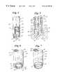
- FIG. 1is a perspective, partial cross-sectional view of a heart wall 10 having an annular hole 12 formed in the myocardium by a catheter made in accordance with the present invention.
- FIG. 2is a perspective, partial crosssectional view of a catheter 20 in accordance with the present invention.
- Catheter 20includes a shaft 21 having a proximal end and a distal end.
- Shaft 21preferably includes an elongate hypotube sandwiched between an inner insulator 24 and an outer insulator 26 .
- Hypotube 22can be formed from stainless steel or Nitinol or other conductive material.
- a nickel-titanium alloyfor example, NITINOLTM, hereafter referred to as nitinol
- nitinolnickel-titanium alloy
- Insulators 24 and 26may be formed from, for example, polyethylene, polyimide or PTFE. Those skilled in the art would appreciate that other biocompatible materials can be used to form these elements.
- the distal end of hypotube 22is preferably left uninsulated to form an annularly-shaped electrode 23 .
- a stop 28is preferably disposed within shaft 21 .
- Stop 28preferably defines a lumen 30 extending therethrough.
- Stop 28includes a distal end 32 spaced a predetermined distance from a distal end 34 of electrode 23 . This predetermined distance can be used to control the depth of holes 12 formed in the myocardium of a patient's heart.
- PEPInon-conductive, biocompatible materials available to form stop 28 , for example PEPI.
- RF generator Gcan be conductively connected to hypotube 22 to deliver RF energy to electrode 23 .
- FIG. 3is a cross-sectional view of catheter 20 in use.
- electrode 23has been energized with RF energy and advanced into heart wall 10 to form hole 12 .
- contrast medium, growth factor or other drugsare being infused through lumen 30 into hole 12 , and then into myocardium 10 .
- distal end 32 of stop 28is spaced a predetermined distance from distal end 34 of electrode 23 such that the depth of hole 12 is approximately equal to its width.
- the predetermined distancecan be varied such that shallower holes or craters are formed, or alternatively the distance can be increased to form channels.
- FIG. 4is a perspective, partial cross-sectional view of catheter 20 modified to include a hypotube or needle 36 extending distally from lumen 30 .
- the distal end of hypotube 36includes a sharpened end 38 , and a lumen defined therethrough in fluid communication with lumen 30 .
- Hypotube 36can also act as a bi-polar ground.
- FIG. 5is a cross-sectional view of catheter 20 including hypotube 36 . This view is similar to that of FIG. 3, except that rather than infusion fluid into hole 12 , as shown by the arrows, fluid is directed into the myocardium.
- FIG. 6is an alternate embodiment of a catheter 120 in accordance with the present invention.
- catheter 120includes a plurality of elongate conductive members 122 embedded in a tubular insulator 124 .
- a distal portion of members 122is preferably left uninsulated to form a generally annularly shaped array of electrodes 123 .
- One or more of electrodes 123may comprise a needle.
- a stop 128is disposed within tubular member 124 . Stop 128 defines a lumen 130 extending therethrough.
- Stop 128includes distal end 132 spaced a predetermined distance proximally of distal ends 134 at electrodes 123 to control the depth of the holes created by catheter 123 .
- catheter 120can be used in substantially the same manner to perform PMR as catheter 20 shown in FIG. 3.
- a plurality of electrodes, having a surface area less than a continuous annular electroderequires less energy to arc or ablate.
- a plurality of electrodeswill also tend to grab tissue, stabilizing the electrode on a moving heart wall.
- FIG. 7is a perspective view of a modified embodiment of catheter 20 of FIG. 2 .
- the distal end of hypotube 22has been serrated to form a serrated electrode 40 .
- Serrating electrode 40changes the surface of the electrode contacting the tissue and thus reduces the power needed to arc.
- Serrated electrode 40will also grab tissue, securing electrode 40 to a moving heart wall during crater formation.
- FIG. 8is a view of yet another embodiment of catheter 20 in accordance with the present invention.
- a second grounded or return electrode 31to form a bi-polar RF PMR catheter. It can be appreciated that this electrode can also be added to catheter 120 of FIG. 6 and catheter 20 of FIG. 7 to make each of these embodiments bi-polar as well.
- FIG. 9is a perspective view of yet another embodiment of a catheter 210 in accordance with the present invention disposed within a guide catheter 212 .
- Catheter 210includes an elongate shaft 214 .
- Elongate shaft 214is preferably formed from an elongate tubular, and conductive member such as a stainless steel or Nitinol hypotube.
- Shaft 214defines an infusion lumen therethrough.
- the wall of the lumen and the exterior shaft 214are preferably insulated, by a layer of, for example, polyethylene.
- An electrode 216is connected to shaft 214 by solder or another conductive connection.
- Electrode 216can be formed from a wire or ribbon shaped member which extends distally from shaft 214 to a generally linearly and transversely extending distal end 218 . All but distal end 218 of electrode 216 can be insulated with, for example, PTFE to focus RF energy at end 218 . Electrode 216 can be partially or completely surrounded by a hood 220 extending from shaft 214 . Hood 220 preferably defines an infusion lumen in fluid communication with the infusion lumen of shaft 214 . All or a portion of electrode 216 can be disposed in the infusion lumen. Hood 220 includes a distal end 222 . Distal end 218 could be plated with gold or other radiopaque material to act as a marker.
- FIG. 10is a cross-sectional view of hood 220 showing electrode 218 extending distally beyond distal end 222 .
- electrode 216is entirely disposed proximally of end 222 .
- distal end 218 of electrode 216is disposed flush with end 222 of hood 220 .
- the relative positioning of hood 220 and electrode 216can have an effect on the depth of craters formed by catheter 210 , as explained in more detail below.
- FIG. 13is a view directly into a crater 223 formed by a typical electrode 218 viewed from a perspective perpendicular to a surface 224 of endocardium 226 .
- Crater 223extends into myocardium 228 of a patient's heart.
- FIG. 14is a cross-sectional view of crater 223 of FIG. 13 .
- the depth D of crater 223is a function of the power delivered to electrode 216 and the relative position of the electrode 216 to distal end 222 of hood 220 .
- the more power delivered to electrode 216the greater the depth of crater 223 .
- the position of electrode distal end 218 relative hood distal end 222 of FIG. 10creates the deepest crater.
- the positioning shown in FIG. 11would create the shallowest, whereas the positioning of FIG. 12 would create a crater of intermediate depth.
- the width W of crater 223is a function of the transverse extent of distal end 218 of electrode 216 , and the power delivered to the electrode. The greater the transverse extent of distal end 218 , the greater the width of crater 223 . The more power that is delivered to electrode 216 , the wider will be crater 223 .
- catheter 210is preferably advanced percutaneous to the endocardium of a patient's heart. This route will normally be by way of the femoral artery and the aorta to the left ventricle. Distal end 222 is brought into contact with the endocardium, preferably, such that the perimeter of distal end 222 is entirely in contact with the endocardium. Electrode 216 disposed in one of the positions shown in FIGS. 10-12, is energized to form a crater. A fluid under pressure is then forced into the crater by way of the infusion lumen through shaft 214 and hood 220 . This fluid can be saline, contrast media, a drug or any combination of these.
- catheter 210As configured in FIG. 12 :
- Output power vs. impedanceis preferably flat across a wide range of impedance values for desired therapeutic power level.
- Exemplary power requirementsa) output power approximately 30-40 watts into 100 to 10,000 ohms; b) output voltage approximately 1,200 to 2,000 V P-P into approximately 100 to 10,000 ohms; c) output current approximately 100 to 300 ma P-P into about 100 to 10,000 ohms voltage is preferably large enough to sustain cutting effect for a given electrode while delivery current as low as possible.
- the RF wave formis preferably 500 KHz or higher unmodulated continuous sine wave.
- the delivery typecan be mono-polar delivery with small area dispersive electrode for lower power applications.
- Delivery controlled by application timerpreferably fixed at about 0.6 to 1.0 seconds.
- angiogenisisis also stimulated by the thermal injury creating the crater, and fluid pressure entering the myocardium from the left ventricle through the endocardium by way of the crater. Hemorrhaging of the subendocardial vasculature may also occur in response to adjacent tissue ruptures or ablation.
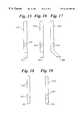
- FIG. 15is a front view of an elongate electrode 300 having an angled distal end 302 . Disposed on the front of electrode 300 is an asymmetrical radiopaque marker 304 . Marker 304 could be formed from, for example, gold or platinum. As electrode 300 is rotated 180° around its longitudinal axis, electrode 300 will appear as shown in FIG. 16 .
- FIG. 16is a fluoroscopic back side view of electrode 300 wherein marker 304 appears in mirror image to its position FIG. 15 .
- FIG. 17is a side view of electrode 300 rotated 90° round about its longitudinal axis relative to its position in FIG. 15 . It can be appreciated that by providing an asymmetrical marker band, the relative rotational position of the catheter or electrode in a patient can be determined by fluoroscopy.
- FIGS. 18 and 19are views of the front and back, respectively of electrode 300 including an alternate marker 306 configured as an F. It can be appreciated that various asymmetrical marker configurations can be used in accordance with the present invention.
- contrast mediacan be infused into the holes, craters, wounds, or channels formed during a PMR procedure. Normal contrast media formulations will tend to dissipate rapidly into the patient's blood stream as the patient's heart continues to beat.
- a mixture of 498 LoctiteTM adhesivecan be radiopaque loaded with platinum or other biocompatible radiopaque material to a weight percentage sufficient to be visible under fluoroscopy.
- the catheters of the present inventioncan be advanced percutaneously to a chamber of a patient's heart, for example, the left ventricle.
- the percutaneous route for advancementwill generally be by way of the femoral artery and the aorta.
- the electrodeis then brought into close proximity with the chamber wall.
- the electrodeis energized and repeatedly plunged into the myocardium to form a plurality of holes.
Landscapes
- Health & Medical Sciences (AREA)
- Life Sciences & Earth Sciences (AREA)
- Surgery (AREA)
- Engineering & Computer Science (AREA)
- Animal Behavior & Ethology (AREA)
- General Health & Medical Sciences (AREA)
- Biomedical Technology (AREA)
- Heart & Thoracic Surgery (AREA)
- Veterinary Medicine (AREA)
- Public Health (AREA)
- Molecular Biology (AREA)
- Nuclear Medicine, Radiotherapy & Molecular Imaging (AREA)
- Medical Informatics (AREA)
- Cardiology (AREA)
- Pathology (AREA)
- Oral & Maxillofacial Surgery (AREA)
- Transplantation (AREA)
- Vascular Medicine (AREA)
- Physics & Mathematics (AREA)
- Plasma & Fusion (AREA)
- Otolaryngology (AREA)
- Media Introduction/Drainage Providing Device (AREA)
- Surgical Instruments (AREA)
Abstract
Description
The present application is related to U.S. Provisional Patent Application Serial No. 60/064,210, filed on Nov. 4, 1997, and entitled TRANSMYOCARDIAL REVASCULARIZATION GROWTH FACTOR MEDIUMS AND METHOD, U.S. patent application Ser. No. 08/812,425, filed on Mar. 6, 1997, now U.S. Pat. No. 5,968,059 entitled TRANSMYOCARDIAL REVASCULARIZATION CATHETER AND METHOD, U.S. patent application Ser. No. 08/810,830, filed Mar. 6, 1997, now U.S. Pat. No. 5,938,632, entitled RADIOFREQUENCY TRANSMYOCARDIAL REVASCULARIZATION APPARATUS AND METHOD, and U.S. patent application Ser. No. 09/035,737, filed on Mar. 5, 1998, now U.S. Pat. No. 6,093,185, and entitled EXPANDABLE PMR DEVICE AND METHOD herein incorporated by reference.
The present invention relates generally to medical devices for forming holes in heart chamber interior walls in percutaneous myocardial revascularization (PMR) procedures. More specifically, the present invention relates to intravascular PMR devices having generally annular tips.
A number of techniques are available for treating cardiovascular disease such as cardiovascular by-pass surgery, coronary angioplasty, laser angioplasty and atherectomy. These techniques are generally applied to by-pass or open lesions in coronary vessels to restore and increase blood flow to the heart muscle. In some patients, the number of lesions are so great, or the location so remote in the patient vasculature that restoring blood flow to the heart muscle is difficult. Percutaneous myocardial revascularization (PMR) has been developed as an alternative to these techniques which are directed at by-passing or removing lesions. Heart muscle may be classified as healthy, hibernating and “dead”. Dead tissue is not dead but is scarred, not contracting, and no longer capable of contracting even if it were supplied adequately with blood. Hibernating tissue is not contracting muscle tissue but is capable of contracting, should it be adequately re-supplied with blood. PMR is performed by boring channels directly into the myocardium of the heart.
PMR was inspired in part by observations that reptilian hearts muscle is supplied primarily by blood perfusing directly from within heart chambers to the heart muscle. This contrasts with the human heart, which is supplied by coronary vessels receiving blood from the aorta. Positive results have been demonstrated in some human patients receiving PMR treatments. These results are believed to be caused in part by blood flowing from within a heart chamber through patent channels formed by PMR to the myocardial tissue. Suitable PMR holes have been burned by laser, cut by mechanical means, and burned by radio frequency current devices. Increased blood flow to the myocardium is also believed to be caused in part by the healing response to wound formation. Specifically, the formation of new blood vessels is believed to occur in response to the newly created wound.
The present invention pertains to a device and method for performing percutaneous myocardial revascularization (PMR). The device of the present invention can be used to form crater wounds in the myocardium of the patient's heart. A crater wound can be viewed as a wound having a width greater than its depth, whereas a channel wound is one having a depth greater than its width. A hole in the myocardium is a volumetric removal of tissue. The device can also be used to form channel wounds, but the configuration of the device's electrode(s) makes the device particularly suitable for creating crater wounds.
In the preferred form of the method in accordance with the present invention, a crater wound is made through the endocardium and into the myocardium. The wound, and thus the healing response, including angiogenisis and subsequent perfusion of tissue is enhanced by collateral damage to the myocardium. The collateral damage is preferably induced by directing pressurized saline, contrast media, drug or a combination into the crater site through the endocardium and into the myocardium. This causes the vessels, capillaries and sinuses to rupture. By creating the collateral damage, the number of wounds which need to be made during the PMR procedure can be substantially reduced as the size of each wound is increased in view of the collateral damage. Additionally, and arguably as significant as the reduction in the number of wounds which must be formed during the procedure, is the reduction of the likelihood of a myocardial perforation. This reduction is possible because the holes can be limited in depth to just through the endocardium. Once the endocardium is perforated, pressure from infused fluid can rupture the myocardial vessels without further ablation or removal of tissue.
In a preferred embodiment, a catheter in accordance with the present invention includes an elongate shaft having a proximal end and a distal end, and a conductor extending therethrough. An electrode is disposed at the distal end of the shaft and connected to the conductor. The electrode has a generally annular transverse crosssectional shape. The annular shape defines an opening within the electrode. An insulator surrounds the elongate shaft.
A stop is disposed in the opening a predetermined distance proximally of the distal end of the electrode. The shaft preferably defines a lumen in fluid communication with the opening through the electrode. In one embodiment, a needle can be disposed within the opening and be in fluid communication with the lumen to deliver contrast media, growth factors or drugs to the wound.
In another embodiment, the annular shape of the electrode is generally circular. The annular shape can be continuous or in an alternate embodiment, discontinuous and formed from a plurality of discrete electrodes positioned in an array. The electrode can also include a serrated edge that produces a plurality of electrode contact points.
A method for performing PMR in accordance with the present invention includes providing a catheter having an elongate shaft including a proximal end and a distal end. A generally annular shaped electrode is disposed at the distal end of the shaft. The electrode is advanced to proximate the endocardial surface of the myocardium of the patient's heart. The electrode is energized and advanced into the myocardium to form an annular shaped crater wound. Depth is controlled by a mechanical stop.
FIG. 1 is a cross-sectional, perspective view of an annular shaped crater wound in a patient's myocardium formed by a device in accordance with the present invention;
FIG. 2 is a perspective, cross-sectional view of a catheter in accordance with the present invention;
FIG. 3 is a cross-sectional view of the catheter of FIG. 2 in use;
FIG. 4 is a perspective, cross-sectional view of an alternate embodiment of the catheter in accordance with the present invention;
FIG. 5 is a cross-sectional view of the catheter of FIG. 4 in use;
FIG. 6 is a perspective view of the distal end of yet another alternate embodiment of a catheter in accordance with the present invention;
FIG. 7 is a perspective view of yet another alternate embodiment of the catheter in accordance with the present invention;
FIG. 8 is a perspective view of yet another alternate embodiment of the catheter in accordance with the present invention;
FIG. 9 is a perspective view of yet another alternate embodiment of the catheter in accordance with the present invention;
FIG. 10 is a cross-sectional view of the catheter of FIG. 8;
FIG. 11 is a cross-sectional view of the catheter of FIG. 8;
FIG. 12 is a cross-sectional view of the catheter of FIG. 8;
FIG. 13 is a top view of a crater formed in the endocardium;
FIG. 14 is a cross-sectional view of the crater of FIG. 12;
FIG. 15 is a front view of a catheter electrode in accordance with the present invention;
FIG. 16 is a back view of the electrode of FIG. 14;
FIG. 17 is a side view of the electrode of FIG. 14;
FIG. 18 is a front view of yet another embodiment of an electrode in accordance with the present invention; and
FIG. 19 is a back view of the electrode of FIG.17.
Referring now the drawings wherein like reference numerals refer to like elements through the several views, FIG. 1 is a perspective, partial cross-sectional view of aheart wall 10 having anannular hole 12 formed in the myocardium by a catheter made in accordance with the present invention. FIG. 2 is a perspective, partial crosssectional view of acatheter 20 in accordance with the present invention.Catheter 20 includes ashaft 21 having a proximal end and a distal end.Shaft 21 preferably includes an elongate hypotube sandwiched between aninner insulator 24 and anouter insulator 26.Hypotube 22 can be formed from stainless steel or Nitinol or other conductive material. It can be desirable to use a nickel-titanium alloy (for example, NITINOL™, hereafter referred to as nitinol) hypotube as the highly flexible material can act as a shock absorber whilecatheter 20 is pressure against the beating heart during the PMR procedure.Insulators hypotube 22 is preferably left uninsulated to form an annularly-shapedelectrode 23.
Astop 28 is preferably disposed withinshaft 21. Stop28 preferably defines alumen 30 extending therethrough.Stop 28 includes adistal end 32 spaced a predetermined distance from adistal end 34 ofelectrode 23. This predetermined distance can be used to control the depth ofholes 12 formed in the myocardium of a patient's heart. Those skilled in the art will recognize the non-conductive, biocompatible materials available to formstop 28, for example PEPI.
In view of the discussion below regarding the use ofcatheter 20, those skilled in the art of catheter construction would recognize the various possibilities for manifolds to be disposed at the proximal end ofcatheter 20, and that a suitable radio frequency (RF) generator G can be conductively connected to hypotube22 to deliver RF energy toelectrode 23.
FIG. 3 is a cross-sectional view ofcatheter 20 in use. In FIG. 3,electrode 23 has been energized with RF energy and advanced intoheart wall 10 to formhole 12. As shown by the arrows, contrast medium, growth factor or other drugs are being infused throughlumen 30 intohole 12, and then intomyocardium 10. It can be noted that in FIG. 3 thatdistal end 32 ofstop 28 is spaced a predetermined distance fromdistal end 34 ofelectrode 23 such that the depth ofhole 12 is approximately equal to its width. The predetermined distance can be varied such that shallower holes or craters are formed, or alternatively the distance can be increased to form channels.
FIG. 4 is a perspective, partial cross-sectional view ofcatheter 20 modified to include a hypotube orneedle 36 extending distally fromlumen 30. The distal end ofhypotube 36 includes a sharpenedend 38, and a lumen defined therethrough in fluid communication withlumen 30.Hypotube 36 can also act as a bi-polar ground.
FIG. 5 is a cross-sectional view ofcatheter 20 includinghypotube 36. This view is similar to that of FIG. 3, except that rather than infusion fluid intohole 12, as shown by the arrows, fluid is directed into the myocardium.
FIG. 6 is an alternate embodiment of acatheter 120 in accordance with the present invention. Many elements ofcatheter 120 are similar to that ofcatheter 20 as shown in FIG.2. Rather thanshaft 121 including ahypotube 22,shaft 121 includes a plurality of elongateconductive members 122 embedded in atubular insulator 124. A distal portion ofmembers 122 is preferably left uninsulated to form a generally annularly shaped array ofelectrodes 123. One or more ofelectrodes 123 may comprise a needle. Astop 128 is disposed withintubular member 124. Stop128 defines alumen 130 extending therethrough. Stop128 includesdistal end 132 spaced a predetermined distance proximally ofdistal ends 134 atelectrodes 123 to control the depth of the holes created bycatheter 123. I can be appreciated by those skilled in the art thatcatheter 120 can be used in substantially the same manner to perform PMR ascatheter 20 shown in FIG. 3. A plurality of electrodes, having a surface area less than a continuous annular electrode requires less energy to arc or ablate. A plurality of electrodes will also tend to grab tissue, stabilizing the electrode on a moving heart wall.
FIG. 7 is a perspective view of a modified embodiment ofcatheter 20 of FIG.2. In particular, the distal end ofhypotube 22 has been serrated to form aserrated electrode 40.Serrating electrode 40 changes the surface of the electrode contacting the tissue and thus reduces the power needed to arc.Serrated electrode 40 will also grab tissue, securingelectrode 40 to a moving heart wall during crater formation.
FIG. 8 is a view of yet another embodiment ofcatheter 20 in accordance with the present invention. Tocatheter 20 has been added a second grounded or returnelectrode 31 to form a bi-polar RF PMR catheter. It can be appreciated that this electrode can also be added tocatheter 120 of FIG.6 andcatheter 20 of FIG. 7 to make each of these embodiments bi-polar as well.
FIG. 9 is a perspective view of yet another embodiment of acatheter 210 in accordance with the present invention disposed within aguide catheter 212.Catheter 210 includes anelongate shaft 214.Elongate shaft 214 is preferably formed from an elongate tubular, and conductive member such as a stainless steel or Nitinol hypotube.Shaft 214 defines an infusion lumen therethrough. The wall of the lumen and theexterior shaft 214 are preferably insulated, by a layer of, for example, polyethylene. Anelectrode 216 is connected toshaft 214 by solder or another conductive connection.
FIG. 10 is a cross-sectional view ofhood 220 showingelectrode 218 extending distally beyonddistal end 222. By contrast, in FIG. 11,electrode 216 is entirely disposed proximally ofend 222. In FIG. 12,distal end 218 ofelectrode 216 is disposed flush withend 222 ofhood 220. The relative positioning ofhood 220 andelectrode 216 can have an effect on the depth of craters formed bycatheter 210, as explained in more detail below.
FIG. 13 is a view directly into acrater 223 formed by atypical electrode 218 viewed from a perspective perpendicular to asurface 224 ofendocardium 226.Crater 223 extends intomyocardium 228 of a patient's heart. FIG. 14 is a cross-sectional view ofcrater 223 of FIG.13.
The depth D ofcrater 223 is a function of the power delivered toelectrode 216 and the relative position of theelectrode 216 todistal end 222 ofhood 220. The more power delivered toelectrode 216, the greater the depth ofcrater 223. With respect to the position ofelectrode 216 relative tohood 220, the position of electrodedistal end 218 relative hooddistal end 222 of FIG. 10 creates the deepest crater. The positioning shown in FIG. 11 would create the shallowest, whereas the positioning of FIG. 12 would create a crater of intermediate depth.
The width W ofcrater 223 is a function of the transverse extent ofdistal end 218 ofelectrode 216, and the power delivered to the electrode. The greater the transverse extent ofdistal end 218, the greater the width ofcrater 223. The more power that is delivered toelectrode 216, the wider will becrater 223.
In use,catheter 210 is preferably advanced percutaneous to the endocardium of a patient's heart. This route will normally be by way of the femoral artery and the aorta to the left ventricle.Distal end 222 is brought into contact with the endocardium, preferably, such that the perimeter ofdistal end 222 is entirely in contact with the endocardium.Electrode 216 disposed in one of the positions shown in FIGS. 10-12, is energized to form a crater. A fluid under pressure is then forced into the crater by way of the infusion lumen throughshaft 214 andhood 220. This fluid can be saline, contrast media, a drug or any combination of these. By forcing fluid under pressure into the myocardium, the vessels, capillaries, and sinuses will be collaterally damaged within anarea 230 aboutcrater 223. This will increase the healing response by angiogenisis associated with the crater. The likelihood of perforating the myocardium is reduced as the depth of the crater need only be sufficient to penetrate the endocardium.
The following are exemplary technical specifications forcatheter 210 as configured in FIG.12:
A. Output power vs. impedance specifications-channel or crater making PMR device;
1. Output power vs. impedance is preferably flat across a wide range of impedance values for desired therapeutic power level.
2. Exemplary power requirements: a) output power approximately 30-40 watts into 100 to 10,000 ohms; b) output voltage approximately 1,200 to 2,000 V P-P into approximately 100 to 10,000 ohms; c) output current approximately 100 to 300 ma P-P into about 100 to 10,000 ohms voltage is preferably large enough to sustain cutting effect for a given electrode while delivery current as low as possible.
B. The RF wave form is preferably 500 KHz or higher unmodulated continuous sine wave.
C. The delivery type can be mono-polar delivery with small area dispersive electrode for lower power applications.
D. RF delivery control.
1. Preferably fixed power to provide cutting effect.
2. Delivery controlled by application timer preferably fixed at about 0.6 to 1.0 seconds.
It can be appreciated, that angiogenisis is also stimulated by the thermal injury creating the crater, and fluid pressure entering the myocardium from the left ventricle through the endocardium by way of the crater. Hemorrhaging of the subendocardial vasculature may also occur in response to adjacent tissue ruptures or ablation.
FIG. 15 is a front view of anelongate electrode 300 having an angleddistal end 302. Disposed on the front ofelectrode 300 is an asymmetricalradiopaque marker 304.Marker 304 could be formed from, for example, gold or platinum. Aselectrode 300 is rotated 180° around its longitudinal axis,electrode 300 will appear as shown in FIG.16. FIG. 16 is a fluoroscopic back side view ofelectrode 300 whereinmarker 304 appears in mirror image to its position FIG.15.
FIG. 17 is a side view ofelectrode 300 rotated 90° round about its longitudinal axis relative to its position in FIG.15. It can be appreciated that by providing an asymmetrical marker band, the relative rotational position of the catheter or electrode in a patient can be determined by fluoroscopy.
FIGS. 18 and 19 are views of the front and back, respectively ofelectrode 300 including analternate marker 306 configured as an F. It can be appreciated that various asymmetrical marker configurations can be used in accordance with the present invention.
It is noted several times above that contrast media can be infused into the holes, craters, wounds, or channels formed during a PMR procedure. Normal contrast media formulations will tend to dissipate rapidly into the patient's blood stream as the patient's heart continues to beat. In order to retain the contrast media within the crater for an extended period of time, a mixture of 498 Loctite™ adhesive can be radiopaque loaded with platinum or other biocompatible radiopaque material to a weight percentage sufficient to be visible under fluoroscopy.
In use, the catheters of the present invention can be advanced percutaneously to a chamber of a patient's heart, for example, the left ventricle. The percutaneous route for advancement will generally be by way of the femoral artery and the aorta. The electrode is then brought into close proximity with the chamber wall. The electrode is energized and repeatedly plunged into the myocardium to form a plurality of holes.
Numerous advantages of the invention covered by this document have been set forth in the foregoing description. It will be understood, however, that this disclosure is, in many respects, only illustrative. Changes may be made in details, particularly in matters of shape, size, and arrangement of parts without exceeding the scope of the invention. The inventions's scope is, of course, defined in the language in which the appended claims are expressed.
Claims (24)
1. A catheter assembly, comprising:
an elongate shaft having a proximal end and a distal end, and including a conductor;
an electrode disposed at the distal end of the shaft and connected to the conductor, the electrode having a generally annular transverse cross-sectional shape, the annular shape defining an opening within the electrode, the electrode having a distal end;
a stop disposed in the opening proximally a distance from the distal end of the electrode;
an insulator surrounding the conductor wherein the shaft defines a lumen in fluid communication with the opening and a needle is disposed within the opening in fluid communication with the lumen; and
wherein the needle has an outside diameter and the opening has an inside diameter and wherein the outside diameter of the needle is substantially smaller than the inside diameter of the opening so that tissue may be disposed within the opening between the needle and the electrode.
2. A catheter assembly in accordance withclaim 1 , wherein the stop is disposed in the opening proximally a predetermined distance from the distal end of the electrode.
3. A catheter assembly in accordance withclaim 1 , wherein the insulator includes polyethylene.
4. A catheter assembly in accordance withclaim 1 , wherein the insulator includes polyimide.
5. A catheter assembly in accordance withclaim 1 , wherein the shaft includes a stainless steel hypotube.
6. A catheter assembly in accordance withclaim 1 , wherein the shaft includes a nickel-titanium alloy hypotube.
7. A catheter assembly in accordance withclaim 1 , further comprising a radiofrequency generator connected to the conductor.
8. A catheter assembly in accordance withclaim 1 , wherein the annular shape is generally circular.
9. A catheter assembly in accordance withclaim 1 , wherein the annular shape is continuous.
10. A catheter assembly in accordance withclaim 1 , wherein the annular shape is discontinuous.
11. A catheter assembly in accordance withclaim 10 , wherein the annular shape is formed by a plurality of electrodes positioned in an array.
12. A catheter assembly in accordance withclaim 1 , wherein the electrode includes a plurality of distally projecting members.
13. A catheter assembly in accordance withclaim 12 , wherein the electrode is serrated to grab tissue.
14. A catheter assembly in accordance withclaim 1 , further comprising a second electrode.
15. A catheter assembly in accordance withclaim 14 , wherein the electrode comprises a needle.
16. A catheter assembly in accordance withclaim 1 , wherein the stop is non-conductive.
17. A catheter assembly, comprising:
an elongate shaft having a proximal end and a distal end, and including a conductor;
an electrode disposed at the distal end of the shaft and connected to the conductor, the electrode having a generally annular transverse cross-sectional shape, the annular shape defining an opening within the electrode, the electrode having a distal end;
a stop disposed in the opening proximally a distance from the distal end of the electrode;
an insulator surrounding the conductor wherein the shaft defines a lumen in fluid communication with the opening and a needle is disposed within the opening in fluid communication with the lumen; and
wherein the needle has an outside diameter and the opening has an inside diameter and wherein the outside diameter of the needle is about one-half or smaller than the inside diameter of the opening.
18. A method of performing PMR, comprising the steps of:
providing a catheter assembly including an elongate shaft having a proximal end and a distal end, and including a conductor; an electrode disposed at the distal end of the shaft and connected to the conductor, the electrode having a generally annular transverse cross-sectional shape, the annular shape defining an opening within the electrode, the electrode having a distal end; a stop disposed in the opening proximally a distance from the distal end of the electrode; an insulator surrounding the conductor wherein the shaft defines a lumen in fluid communication with the opening and a needle is disposed within the opening in fluid communication with the lumen; and wherein the needle has an outside diameter and the opening has an inside diameter and wherein the outside diameter of the needle is substantially smaller than the inside diameter of the opening so that tissue may be disposed within the opening between the needle and the electrode;
advancing the catheter assembly to a location proximate a wall of a patient's heart;
energizing the electrode; and
advancing the electrode into the wall of the patient's heart.
19. The method in accordance withclaim 18 , wherein the step of advancing the electrode into the wall of the patient's heart includes forming a hole having a depth defined by the distance between the distal end of the electrode and the stop.
20. The method in accordance withclaim 18 , wherein the step of advancing the electrode into the wall of the patient's heart includes contacting the stop with the wall of the patient's heart.
21. The method in accordance withclaim 18 , wherein the step of advancing the electrode into the wall of the patient's heart includes disposing at least a portion of the wall of the patient's heart within the opening between the needle and the electrode.
22. The method in accordance withclaim 18 , further comprising the step of delivering saline through the needle.
23. The method in accordance withclaim 18 , further comprising the step of delivering a drug through the needle.
24. The method in accordance withclaim 18 , further comprising the step of infusing fluid into the wall of the patient's heart through the needle.
Priority Applications (9)
| Application Number | Priority Date | Filing Date | Title |
|---|---|---|---|
| US09/035,736US6416490B1 (en) | 1997-11-04 | 1998-03-05 | PMR device and method |
| JP2000534132AJP2002505139A (en) | 1998-03-05 | 1999-03-05 | PMR apparatus and method |
| EP99911163AEP1058516B1 (en) | 1998-03-05 | 1999-03-05 | Pmr device |
| ES99911163TES2252936T3 (en) | 1998-03-05 | 1999-03-05 | MIOCARDIC PERCUTANEOUS REVASCULARIZATION DEVICE (PMR). |
| DE99911163TDE99911163T1 (en) | 1998-03-05 | 1999-03-05 | DEVICE AND METHOD FOR PMR |
| PCT/US1999/004942WO1999044523A1 (en) | 1998-03-05 | 1999-03-05 | Pmr device and method |
| DE69928499TDE69928499T2 (en) | 1998-03-05 | 1999-03-05 | DEVICE FOR PMR |
| CA002322452ACA2322452A1 (en) | 1998-03-05 | 1999-03-05 | Pmr device and method |
| US10/154,737US20020143289A1 (en) | 1997-11-04 | 2002-05-23 | PMR device and method |
Applications Claiming Priority (2)
| Application Number | Priority Date | Filing Date | Title |
|---|---|---|---|
| US6421097P | 1997-11-04 | 1997-11-04 | |
| US09/035,736US6416490B1 (en) | 1997-11-04 | 1998-03-05 | PMR device and method |
Related Child Applications (1)
| Application Number | Title | Priority Date | Filing Date |
|---|---|---|---|
| US10/154,737ContinuationUS20020143289A1 (en) | 1997-11-04 | 2002-05-23 | PMR device and method |
Publications (1)
| Publication Number | Publication Date |
|---|---|
| US6416490B1true US6416490B1 (en) | 2002-07-09 |
Family
ID=21884497
Family Applications (2)
| Application Number | Title | Priority Date | Filing Date |
|---|---|---|---|
| US09/035,736Expired - Fee RelatedUS6416490B1 (en) | 1997-11-04 | 1998-03-05 | PMR device and method |
| US10/154,737AbandonedUS20020143289A1 (en) | 1997-11-04 | 2002-05-23 | PMR device and method |
Family Applications After (1)
| Application Number | Title | Priority Date | Filing Date |
|---|---|---|---|
| US10/154,737AbandonedUS20020143289A1 (en) | 1997-11-04 | 2002-05-23 | PMR device and method |
Country Status (7)
| Country | Link |
|---|---|
| US (2) | US6416490B1 (en) |
| EP (1) | EP1058516B1 (en) |
| JP (1) | JP2002505139A (en) |
| CA (1) | CA2322452A1 (en) |
| DE (2) | DE69928499T2 (en) |
| ES (1) | ES2252936T3 (en) |
| WO (1) | WO1999044523A1 (en) |
Cited By (59)
| Publication number | Priority date | Publication date | Assignee | Title |
|---|---|---|---|---|
| US20020058897A1 (en)* | 1998-09-10 | 2002-05-16 | Percardia, Inc. | Designs for left ventricular conduit |
| US20020072717A1 (en)* | 2000-06-26 | 2002-06-13 | Mueller Richard L. | Method and apparatus for treating ischemic tissue |
| US20030137008A1 (en)* | 2000-03-28 | 2003-07-24 | Hidetoshi Nozaki | Solid state imaging device having a photodiode and a MOSFET and method of manufacturing the same |
| US6666863B2 (en)* | 2001-03-01 | 2003-12-23 | Scimed Life Systems, Inc. | Device and method for percutaneous myocardial revascularization |
| US20040133969A1 (en)* | 2003-01-10 | 2004-07-15 | Tyler Pipe Company, A Division Of Ransom Industries, Lp | Closet carrier system and method of assembly |
| US20040147963A1 (en)* | 2002-10-02 | 2004-07-29 | Medtronic, Inc. | Medical fluid delivery system |
| USD497992S1 (en) | 2002-04-17 | 2004-11-02 | Synergetics, Inc. | Ultrasonic surgical aspiration tip |
| US6854467B2 (en) | 2000-05-04 | 2005-02-15 | Percardia, Inc. | Methods and devices for delivering a ventricular stent |
| US20050049454A1 (en)* | 2003-08-27 | 2005-03-03 | Pentax Corporation | Endoscopic high-frequency knife |
| US6881199B2 (en) | 1998-09-10 | 2005-04-19 | Percardia, Inc. | Left ventricular conduit with blood vessel graft |
| US20050113686A1 (en)* | 2003-11-21 | 2005-05-26 | Peckham John E. | Rotational markers |
| US6916304B2 (en) | 1999-05-04 | 2005-07-12 | Percardia, Inc. | Transmyocardial implant with flow reduction |
| US6945949B2 (en) | 1998-01-30 | 2005-09-20 | Percardia, Inc. | Left ventricular conduits to coronary arteries and methods for coronary bypass |
| US6949118B2 (en) | 2002-01-16 | 2005-09-27 | Percardia, Inc. | Encased implant and methods |
| US6953481B2 (en) | 1998-09-10 | 2005-10-11 | Percardia, Inc. | Designs for left ventricular conduit |
| US6964652B2 (en) | 1999-08-04 | 2005-11-15 | Percardia, Inc. | Left ventricular conduits and methods for delivery |
| US6976990B2 (en) | 2001-01-25 | 2005-12-20 | Percardia, Inc. | Intravascular ventriculocoronary bypass via a septal passageway |
| US7008397B2 (en) | 2002-02-13 | 2006-03-07 | Percardia, Inc. | Cardiac implant and methods |
| US7011095B2 (en) | 1998-09-10 | 2006-03-14 | Percardia, Inc. | Valve designs for left ventricular conduits |
| US7033372B1 (en) | 1999-08-04 | 2006-04-25 | Percardia, Inc. | Corkscrew reinforced left ventricle to coronary artery channel |
| US20060200168A1 (en)* | 2005-03-03 | 2006-09-07 | Azam Anwar | System and method for providing access in divergent directions in a vascular environment |
| WO2007047761A1 (en)* | 2005-10-17 | 2007-04-26 | Arryx, Inc. | Apparatus and method for detecting deformability of cells using spatially modulated optical force microscopy |
| US20070135818A1 (en)* | 2003-09-03 | 2007-06-14 | Bolton Medical, Inc. | Aligning device for stent graft delivery system |
| US7326219B2 (en) | 2002-09-09 | 2008-02-05 | Wilk Patent Development | Device for placing transmyocardial implant |
| US20080132759A1 (en)* | 2004-12-17 | 2008-06-05 | Kyoto University | Cap Attachment with Excising Function and Endoscope |
| US7396351B2 (en) | 2003-11-05 | 2008-07-08 | Boston Scientific Scimed, Inc. | Device and method for the delivery of viscous fluids in the body |
| US20090105654A1 (en)* | 2007-10-19 | 2009-04-23 | Paul Kurth | Transseptal guidewire |
| US20090182281A1 (en)* | 2008-01-16 | 2009-07-16 | Pressure Products Medical Supplies Inc. | Apparatus, system, and method of shielding the sharp tip of a transseptal guidewire |
| US20100191234A1 (en)* | 2009-01-28 | 2010-07-29 | Spine Design, Inc. | Combination Tissue Removal and Cauterization Instrument |
| US8252016B2 (en) | 2005-01-13 | 2012-08-28 | Azam Anwar | System and method for providing embolic protection |
| WO2013123007A1 (en)* | 2012-02-13 | 2013-08-22 | Neurodyamics, Llc | Catheter for use in revascularization procedures and method of using same |
| US8979877B2 (en) | 2010-07-02 | 2015-03-17 | Neurodynamics, LLC | Catheter for use in revascularization procedures and method of using same |
| US9364314B2 (en) | 2008-06-30 | 2016-06-14 | Bolton Medical, Inc. | Abdominal aortic aneurysms: systems and methods of use |
| US9439751B2 (en) | 2013-03-15 | 2016-09-13 | Bolton Medical, Inc. | Hemostasis valve and delivery systems |
| US9554929B2 (en) | 2012-04-12 | 2017-01-31 | Bolton Medical, Inc. | Vascular prosthetic delivery device and method of use |
| US9561124B2 (en) | 2003-09-03 | 2017-02-07 | Bolton Medical, Inc. | Methods of self-aligning stent grafts |
| US9827123B2 (en) | 2009-03-13 | 2017-11-28 | Bolton Medical, Inc. | System for deploying an endoluminal prosthesis at a surgical site |
| US9877857B2 (en) | 2003-09-03 | 2018-01-30 | Bolton Medical, Inc. | Sheath capture device for stent graft delivery system and method for operating same |
| US9883882B2 (en) | 2013-04-24 | 2018-02-06 | Medovex Corp. | Minimally invasive methods for spinal facet therapy to alleviate pain and associated surgical tools, kits and instructional media |
| USD810290S1 (en) | 2016-01-29 | 2018-02-13 | Medovex Corp. | Surgical portal driver |
| US9907686B2 (en) | 2003-09-03 | 2018-03-06 | Bolton Medical, Inc. | System for implanting a prosthesis |
| US9980771B2 (en) | 2014-07-30 | 2018-05-29 | Medovex Corp. | Surgical tools for spinal facet therapy to alleviate pain and related methods |
| US10105250B2 (en) | 2003-09-03 | 2018-10-23 | Bolton Medical, Inc. | Dual capture device for stent graft delivery system and method for capturing a stent graft |
| US10398494B2 (en) | 2014-07-30 | 2019-09-03 | Medovex Corp. | Surgical tools for spinal facet therapy to alleviate pain and related methods |
| US10595919B2 (en) | 2014-12-12 | 2020-03-24 | Medovex Corp. | Surgical tools with positional components |
| US10646365B2 (en) | 2003-09-03 | 2020-05-12 | Bolton Medical, Inc. | Delivery system and method for self-centering a proximal end of a stent graft |
| US10993805B2 (en) | 2008-02-26 | 2021-05-04 | Jenavalve Technology, Inc. | Stent for the positioning and anchoring of a valvular prosthesis in an implantation site in the heart of a patient |
| US11065138B2 (en) | 2016-05-13 | 2021-07-20 | Jenavalve Technology, Inc. | Heart valve prosthesis delivery system and method for delivery of heart valve prosthesis with introducer sheath and loading system |
| US11185405B2 (en) | 2013-08-30 | 2021-11-30 | Jenavalve Technology, Inc. | Radially collapsible frame for a prosthetic valve and method for manufacturing such a frame |
| US11197754B2 (en) | 2017-01-27 | 2021-12-14 | Jenavalve Technology, Inc. | Heart valve mimicry |
| US11259945B2 (en) | 2003-09-03 | 2022-03-01 | Bolton Medical, Inc. | Dual capture device for stent graft delivery system and method for capturing a stent graft |
| US11337800B2 (en) | 2015-05-01 | 2022-05-24 | Jenavalve Technology, Inc. | Device and method with reduced pacemaker rate in heart valve replacement |
| US11357624B2 (en) | 2007-04-13 | 2022-06-14 | Jenavalve Technology, Inc. | Medical device for treating a heart valve insufficiency |
| US11517431B2 (en) | 2005-01-20 | 2022-12-06 | Jenavalve Technology, Inc. | Catheter system for implantation of prosthetic heart valves |
| US11564794B2 (en) | 2008-02-26 | 2023-01-31 | Jenavalve Technology, Inc. | Stent for the positioning and anchoring of a valvular prosthesis in an implantation site in the heart of a patient |
| US11589981B2 (en) | 2010-05-25 | 2023-02-28 | Jenavalve Technology, Inc. | Prosthetic heart valve and transcatheter delivered endoprosthesis comprising a prosthetic heart valve and a stent |
| US12121461B2 (en) | 2015-03-20 | 2024-10-22 | Jenavalve Technology, Inc. | Heart valve prosthesis delivery system and method for delivery of heart valve prosthesis with introducer sheath |
| US12171658B2 (en) | 2022-11-09 | 2024-12-24 | Jenavalve Technology, Inc. | Catheter system for sequential deployment of an expandable implant |
| US12414854B2 (en) | 2010-05-20 | 2025-09-16 | Jenavalve Technology, Inc. | Catheter system for introducing an expandable stent into the body of a patient |
Families Citing this family (50)
| Publication number | Priority date | Publication date | Assignee | Title |
|---|---|---|---|---|
| US6281175B1 (en) | 1997-09-23 | 2001-08-28 | Scimed Life Systems, Inc. | Medical emulsion for lubrication and delivery of drugs |
| US5980548A (en) | 1997-10-29 | 1999-11-09 | Kensey Nash Corporation | Transmyocardial revascularization system |
| US6149646A (en)* | 1999-02-02 | 2000-11-21 | Linvatec Corporation | Monopolar tissue ablator |
| US6709427B1 (en) | 1999-08-05 | 2004-03-23 | Kensey Nash Corporation | Systems and methods for delivering agents into targeted tissue of a living being |
| DE19953938A1 (en)* | 1999-11-09 | 2001-05-10 | Norbert Heske | Device for the gentle removal of tissue from animal or human tissue |
| US6695836B1 (en)* | 2000-07-03 | 2004-02-24 | Radius Medical Technologies, Inc. | Device and method for myocardial revascularization |
| US20040082859A1 (en) | 2002-07-01 | 2004-04-29 | Alan Schaer | Method and apparatus employing ultrasound energy to treat body sphincters |
| US7837676B2 (en)* | 2003-02-20 | 2010-11-23 | Recor Medical, Inc. | Cardiac ablation devices |
| US10499937B2 (en) | 2006-05-19 | 2019-12-10 | Recor Medical, Inc. | Ablation device with optimized input power profile and method of using the same |
| US20110257723A1 (en) | 2006-11-07 | 2011-10-20 | Dc Devices, Inc. | Devices and methods for coronary sinus pressure relief |
| EP2097012A4 (en) | 2006-11-07 | 2012-08-15 | David Stephen Celermajer | Devices and methods for the treatment of heart failure |
| US10413284B2 (en) | 2006-11-07 | 2019-09-17 | Corvia Medical, Inc. | Atrial pressure regulation with control, sensing, monitoring and therapy delivery |
| US9232997B2 (en) | 2006-11-07 | 2016-01-12 | Corvia Medical, Inc. | Devices and methods for retrievable intra-atrial implants |
| US8262626B2 (en)* | 2007-10-23 | 2012-09-11 | Boston Scientific Scimed, Inc. | Apparatus and method for treating tissue |
| WO2010080886A1 (en) | 2009-01-09 | 2010-07-15 | Recor Medical, Inc. | Methods and apparatus for treatment of mitral valve in insufficiency |
| US8954161B2 (en) | 2012-06-01 | 2015-02-10 | Advanced Cardiac Therapeutics, Inc. | Systems and methods for radiometrically measuring temperature and detecting tissue contact prior to and during tissue ablation |
| US9277961B2 (en) | 2009-06-12 | 2016-03-08 | Advanced Cardiac Therapeutics, Inc. | Systems and methods of radiometrically determining a hot-spot temperature of tissue being treated |
| US9226791B2 (en) | 2012-03-12 | 2016-01-05 | Advanced Cardiac Therapeutics, Inc. | Systems for temperature-controlled ablation using radiometric feedback |
| US8926605B2 (en) | 2012-02-07 | 2015-01-06 | Advanced Cardiac Therapeutics, Inc. | Systems and methods for radiometrically measuring temperature during tissue ablation |
| US9757107B2 (en) | 2009-09-04 | 2017-09-12 | Corvia Medical, Inc. | Methods and devices for intra-atrial shunts having adjustable sizes |
| WO2011094521A2 (en) | 2010-01-29 | 2011-08-04 | Dc Devices, Inc. | Devices and methods for reducing venous pressure |
| EP2528646A4 (en) | 2010-01-29 | 2017-06-28 | DC Devices, Inc. | Devices and systems for treating heart failure |
| US12303119B2 (en) | 2011-02-10 | 2025-05-20 | Corvia Medical, Inc. | Apparatus and methods to create and maintain an intra-atrial pressure relief opening |
| WO2012109557A2 (en)* | 2011-02-10 | 2012-08-16 | Dc Devices, Inc. | Apparatus and methods to create and maintain an intra-atrial pressure relief opening |
| US8951223B2 (en) | 2011-12-22 | 2015-02-10 | Dc Devices, Inc. | Methods and devices for intra-atrial shunts having adjustable sizes |
| US9005155B2 (en) | 2012-02-03 | 2015-04-14 | Dc Devices, Inc. | Devices and methods for treating heart failure |
| US10588611B2 (en) | 2012-04-19 | 2020-03-17 | Corvia Medical Inc. | Implant retention attachment and method of use |
| US9649480B2 (en) | 2012-07-06 | 2017-05-16 | Corvia Medical, Inc. | Devices and methods of treating or ameliorating diastolic heart failure through pulmonary valve intervention |
| US9775636B2 (en) | 2013-03-12 | 2017-10-03 | Corvia Medical, Inc. | Devices, systems, and methods for treating heart failure |
| WO2014159276A1 (en) | 2013-03-14 | 2014-10-02 | Recor Medical, Inc. | Ultrasound-based neuromodulation system |
| US10675450B2 (en) | 2014-03-12 | 2020-06-09 | Corvia Medical, Inc. | Devices and methods for treating heart failure |
| JP6799526B2 (en) | 2014-07-23 | 2020-12-16 | コルヴィア メディカル インコーポレイテッド | Equipment and methods for the treatment of heart failure |
| WO2016081611A1 (en) | 2014-11-19 | 2016-05-26 | Advanced Cardiac Therapeutics, Inc. | High-resolution mapping of tissue with pacing |
| JP6725178B2 (en) | 2014-11-19 | 2020-07-15 | エピックス セラピューティクス,インコーポレイテッド | Ablation apparatus, systems and methods using high resolution electrode assemblies |
| JP6825789B2 (en) | 2014-11-19 | 2021-02-03 | エピックス セラピューティクス,インコーポレイテッド | Systems and methods for high resolution mapping of tissues |
| JP6461193B2 (en)* | 2014-11-28 | 2019-01-30 | オリンパス株式会社 | Ablation device |
| US9636164B2 (en) | 2015-03-25 | 2017-05-02 | Advanced Cardiac Therapeutics, Inc. | Contact sensing systems and methods |
| US10905458B2 (en) | 2015-06-08 | 2021-02-02 | Covidien Lp | Tissue-removing catheter, tissue-removing element, and method of making same |
| US10905459B2 (en) | 2015-06-08 | 2021-02-02 | Covidien Lp | Tissue-removing catheter, tissue-removing element, and method of making same |
| US20170007276A1 (en)* | 2015-07-07 | 2017-01-12 | Empire Technology Development Llc | Gallstone removal through cholecystoduodenal fistula by anastomosis device |
| US10631894B2 (en) | 2015-07-15 | 2020-04-28 | Covidien Lp | Tissue-removing catheter, tissue-removing element, and method of making same |
| US10507036B2 (en) | 2016-01-13 | 2019-12-17 | Covidien LLP | Tissue-removing catheter, tissue-removing element, and method of making same |
| WO2017160808A1 (en) | 2016-03-15 | 2017-09-21 | Advanced Cardiac Therapeutics, Inc. | Improved devices, systems and methods for irrigated ablation |
| CN110809448B (en) | 2017-04-27 | 2022-11-25 | Epix疗法公司 | Determining properties of contact between catheter tip and tissue |
| JP6815610B1 (en) | 2019-08-08 | 2021-01-20 | リバーフィールド株式会社 | High frequency forceps |
| US11960624B2 (en) | 2020-02-21 | 2024-04-16 | Immuta, Inc. | Systems and methods to enhance privacy through decision tree based suppression rules on relational databases |
| US11783077B2 (en)* | 2020-06-19 | 2023-10-10 | Immuta, Inc. | Systems and methods for privacy-enhancing modification of a database query |
| WO2022155334A1 (en)* | 2021-01-14 | 2022-07-21 | Medtronic Holding Company Sárl | Ablation devices and methods of manufacturing the same |
| US20230040816A1 (en)* | 2021-08-03 | 2023-02-09 | Medtronic Advanced Energy Llc | Energized corers with powered conveying |
| US12303189B2 (en)* | 2021-08-03 | 2025-05-20 | Medtronic Advanced Energy Llc | Energized corers with energized internals |
Citations (37)
| Publication number | Priority date | Publication date | Assignee | Title |
|---|---|---|---|---|
| US4790311A (en) | 1986-06-03 | 1988-12-13 | Ruiz Oscar F | Radio frequency angioplasty catheter system |
| US4896671A (en) | 1988-08-01 | 1990-01-30 | C. R. Bard, Inc. | Catheter with contoured ablation electrode |
| US5047026A (en) | 1989-09-29 | 1991-09-10 | Everest Medical Corporation | Electrosurgical implement for tunneling through tissue |
| US5093877A (en) | 1990-10-30 | 1992-03-03 | Advanced Cardiovascular Systems | Optical fiber lasing apparatus lens |
| US5209749A (en) | 1990-05-11 | 1993-05-11 | Applied Urology Inc. | Fluoroscopically alignable cutter assembly and method of using the same |
| US5281218A (en)* | 1992-06-05 | 1994-01-25 | Cardiac Pathways Corporation | Catheter having needle electrode for radiofrequency ablation |
| US5358485A (en) | 1992-01-13 | 1994-10-25 | Schneider (Usa) Inc. | Cutter for atherectomy catheter |
| US5364393A (en) | 1990-07-02 | 1994-11-15 | Heart Technology, Inc. | Tissue dissipative recanalization catheter |
| US5370675A (en) | 1992-08-12 | 1994-12-06 | Vidamed, Inc. | Medical probe device and method |
| US5380316A (en) | 1990-12-18 | 1995-01-10 | Advanced Cardiovascular Systems, Inc. | Method for intra-operative myocardial device revascularization |
| US5389096A (en) | 1990-12-18 | 1995-02-14 | Advanced Cardiovascular Systems | System and method for percutaneous myocardial revascularization |
| US5403311A (en) | 1993-03-29 | 1995-04-04 | Boston Scientific Corporation | Electro-coagulation and ablation and other electrotherapeutic treatments of body tissue |
| US5431649A (en) | 1993-08-27 | 1995-07-11 | Medtronic, Inc. | Method and apparatus for R-F ablation |
| US5522815A (en)* | 1993-03-29 | 1996-06-04 | Durgin, Jr.; Russell F. | Integrated catheter for diverse in situ tissue therapy |
| DE29609350U1 (en) | 1996-05-24 | 1996-08-29 | Dr.-Ing. P. Osypka mbH Gesellschaft für Medizintechnik, 79639 Grenzach-Wyhlen | Device for perforating the heart wall |
| WO1996035469A1 (en) | 1995-05-10 | 1996-11-14 | Cardiogenesis Corporation | System for treating or diagnosing heart tissue |
| WO1996039963A1 (en) | 1995-06-07 | 1996-12-19 | Abela Laser Systems, Inc. | Optical fiber catheter and method |
| US5591159A (en) | 1994-11-09 | 1997-01-07 | Taheri; Syde A. | Transcavitary myocardial perfusion apparatus |
| US5593405A (en) | 1994-07-16 | 1997-01-14 | Osypka; Peter | Fiber optic endoscope |
| US5607405A (en) | 1992-05-19 | 1997-03-04 | Decker; Rand A. | Surgical insertion device and method |
| DE19537084A1 (en) | 1995-10-05 | 1997-04-10 | Sievers Hans Hinrich Prof Dr M | Catheter for transmyocardial revasculation with guidable multi=ID main catheter |
| US5620414A (en) | 1992-06-30 | 1997-04-15 | Campbell, Jr.; Robert M. | Apparatus and method for effecting surgical incision through use of a fluid jet |
| WO1997018768A1 (en) | 1995-11-22 | 1997-05-29 | Arthrocare Corporation | Systems and methods for electrosurgical myocardial revascularization |
| WO1997029803A1 (en) | 1996-02-20 | 1997-08-21 | Cormedica | Percutaneous endomyocardial revascularization |
| WO1997032551A1 (en) | 1996-03-04 | 1997-09-12 | Energy Life Systems Corporation | Device and method for trans myocardial revascularization |
| US5672174A (en) | 1995-08-15 | 1997-09-30 | Rita Medical Systems, Inc. | Multiple antenna ablation apparatus and method |
| US5681308A (en) | 1994-06-24 | 1997-10-28 | Stuart D. Edwards | Ablation apparatus for cardiac chambers |
| EP0807412A1 (en) | 1996-05-13 | 1997-11-19 | United States Surgical Corporation | Coring device and method |
| WO1997044071A1 (en) | 1996-05-21 | 1997-11-27 | Amnon Sudai | Apparatus and methods for revascularization and perfusion |
| US5697882A (en) | 1992-01-07 | 1997-12-16 | Arthrocare Corporation | System and method for electrosurgical cutting and ablation |
| US5700259A (en) | 1990-09-24 | 1997-12-23 | Plc Medical Systems, Inc. | Thoracoscopic transmyocardial revascularization handpiece assembly |
| US5713894A (en) | 1996-02-27 | 1998-02-03 | Murphy-Chutorian; Douglas | Combined mechanical/optical system for transmyocardial revascularization |
| US5725521A (en) | 1996-03-29 | 1998-03-10 | Eclipse Surgical Technologies, Inc. | Depth stop apparatus and method for laser-assisted transmyocardial revascularization and other surgical applications |
| US5725523A (en) | 1996-03-29 | 1998-03-10 | Mueller; Richard L. | Lateral-and posterior-aspect method and apparatus for laser-assisted transmyocardial revascularization and other surgical applications |
| US5807395A (en)* | 1993-08-27 | 1998-09-15 | Medtronic, Inc. | Method and apparatus for RF ablation and hyperthermia |
| US6165188A (en)* | 1996-12-02 | 2000-12-26 | Angiotrax, Inc. | Apparatus for percutaneously performing myocardial revascularization having controlled cutting depth and methods of use |
| US6193717B1 (en)* | 1997-10-16 | 2001-02-27 | Asahi Kogaku Kogyo Kabushiki Kaisha | Treating instrument for endoscope |
Family Cites Families (1)
| Publication number | Priority date | Publication date | Assignee | Title |
|---|---|---|---|---|
| US4896971A (en)* | 1987-03-26 | 1990-01-30 | General Signal Corporation | Mixing apparatus |
- 1998
- 1998-03-05USUS09/035,736patent/US6416490B1/ennot_activeExpired - Fee Related
- 1999
- 1999-03-05DEDE69928499Tpatent/DE69928499T2/ennot_activeExpired - Fee Related
- 1999-03-05EPEP99911163Apatent/EP1058516B1/ennot_activeExpired - Lifetime
- 1999-03-05WOPCT/US1999/004942patent/WO1999044523A1/enactiveIP Right Grant
- 1999-03-05ESES99911163Tpatent/ES2252936T3/ennot_activeExpired - Lifetime
- 1999-03-05DEDE99911163Tpatent/DE99911163T1/enactivePending
- 1999-03-05JPJP2000534132Apatent/JP2002505139A/enactivePending
- 1999-03-05CACA002322452Apatent/CA2322452A1/ennot_activeAbandoned
- 2002
- 2002-05-23USUS10/154,737patent/US20020143289A1/ennot_activeAbandoned
Patent Citations (40)
| Publication number | Priority date | Publication date | Assignee | Title |
|---|---|---|---|---|
| US4790311A (en) | 1986-06-03 | 1988-12-13 | Ruiz Oscar F | Radio frequency angioplasty catheter system |
| US4896671A (en) | 1988-08-01 | 1990-01-30 | C. R. Bard, Inc. | Catheter with contoured ablation electrode |
| US5047026A (en) | 1989-09-29 | 1991-09-10 | Everest Medical Corporation | Electrosurgical implement for tunneling through tissue |
| US5209749A (en) | 1990-05-11 | 1993-05-11 | Applied Urology Inc. | Fluoroscopically alignable cutter assembly and method of using the same |
| US5364393A (en) | 1990-07-02 | 1994-11-15 | Heart Technology, Inc. | Tissue dissipative recanalization catheter |
| US5700259A (en) | 1990-09-24 | 1997-12-23 | Plc Medical Systems, Inc. | Thoracoscopic transmyocardial revascularization handpiece assembly |
| US5093877A (en) | 1990-10-30 | 1992-03-03 | Advanced Cardiovascular Systems | Optical fiber lasing apparatus lens |
| US5389096A (en) | 1990-12-18 | 1995-02-14 | Advanced Cardiovascular Systems | System and method for percutaneous myocardial revascularization |
| US5380316A (en) | 1990-12-18 | 1995-01-10 | Advanced Cardiovascular Systems, Inc. | Method for intra-operative myocardial device revascularization |
| US5697882A (en) | 1992-01-07 | 1997-12-16 | Arthrocare Corporation | System and method for electrosurgical cutting and ablation |
| US5871469A (en)* | 1992-01-07 | 1999-02-16 | Arthro Care Corporation | System and method for electrosurgical cutting and ablation |
| US5683366A (en) | 1992-01-07 | 1997-11-04 | Arthrocare Corporation | System and method for electrosurgical tissue canalization |
| US5358485A (en) | 1992-01-13 | 1994-10-25 | Schneider (Usa) Inc. | Cutter for atherectomy catheter |
| US5607405A (en) | 1992-05-19 | 1997-03-04 | Decker; Rand A. | Surgical insertion device and method |
| US5281218A (en)* | 1992-06-05 | 1994-01-25 | Cardiac Pathways Corporation | Catheter having needle electrode for radiofrequency ablation |
| US5620414A (en) | 1992-06-30 | 1997-04-15 | Campbell, Jr.; Robert M. | Apparatus and method for effecting surgical incision through use of a fluid jet |
| US5370675A (en) | 1992-08-12 | 1994-12-06 | Vidamed, Inc. | Medical probe device and method |
| EP0629382A1 (en) | 1992-08-12 | 1994-12-21 | Vidamed, Inc. | Medical probe device and method |
| US5522815A (en)* | 1993-03-29 | 1996-06-04 | Durgin, Jr.; Russell F. | Integrated catheter for diverse in situ tissue therapy |
| US5403311A (en) | 1993-03-29 | 1995-04-04 | Boston Scientific Corporation | Electro-coagulation and ablation and other electrotherapeutic treatments of body tissue |
| US5431649A (en) | 1993-08-27 | 1995-07-11 | Medtronic, Inc. | Method and apparatus for R-F ablation |
| US5807395A (en)* | 1993-08-27 | 1998-09-15 | Medtronic, Inc. | Method and apparatus for RF ablation and hyperthermia |
| US5681308A (en) | 1994-06-24 | 1997-10-28 | Stuart D. Edwards | Ablation apparatus for cardiac chambers |
| US5593405A (en) | 1994-07-16 | 1997-01-14 | Osypka; Peter | Fiber optic endoscope |
| US5591159A (en) | 1994-11-09 | 1997-01-07 | Taheri; Syde A. | Transcavitary myocardial perfusion apparatus |
| WO1996035469A1 (en) | 1995-05-10 | 1996-11-14 | Cardiogenesis Corporation | System for treating or diagnosing heart tissue |
| WO1996039963A1 (en) | 1995-06-07 | 1996-12-19 | Abela Laser Systems, Inc. | Optical fiber catheter and method |
| US5672174A (en) | 1995-08-15 | 1997-09-30 | Rita Medical Systems, Inc. | Multiple antenna ablation apparatus and method |
| DE19537084A1 (en) | 1995-10-05 | 1997-04-10 | Sievers Hans Hinrich Prof Dr M | Catheter for transmyocardial revasculation with guidable multi=ID main catheter |
| WO1997018768A1 (en) | 1995-11-22 | 1997-05-29 | Arthrocare Corporation | Systems and methods for electrosurgical myocardial revascularization |
| WO1997029803A1 (en) | 1996-02-20 | 1997-08-21 | Cormedica | Percutaneous endomyocardial revascularization |
| US5713894A (en) | 1996-02-27 | 1998-02-03 | Murphy-Chutorian; Douglas | Combined mechanical/optical system for transmyocardial revascularization |
| WO1997032551A1 (en) | 1996-03-04 | 1997-09-12 | Energy Life Systems Corporation | Device and method for trans myocardial revascularization |
| US5725521A (en) | 1996-03-29 | 1998-03-10 | Eclipse Surgical Technologies, Inc. | Depth stop apparatus and method for laser-assisted transmyocardial revascularization and other surgical applications |
| US5725523A (en) | 1996-03-29 | 1998-03-10 | Mueller; Richard L. | Lateral-and posterior-aspect method and apparatus for laser-assisted transmyocardial revascularization and other surgical applications |
| EP0807412A1 (en) | 1996-05-13 | 1997-11-19 | United States Surgical Corporation | Coring device and method |
| WO1997044071A1 (en) | 1996-05-21 | 1997-11-27 | Amnon Sudai | Apparatus and methods for revascularization and perfusion |
| DE29609350U1 (en) | 1996-05-24 | 1996-08-29 | Dr.-Ing. P. Osypka mbH Gesellschaft für Medizintechnik, 79639 Grenzach-Wyhlen | Device for perforating the heart wall |
| US6165188A (en)* | 1996-12-02 | 2000-12-26 | Angiotrax, Inc. | Apparatus for percutaneously performing myocardial revascularization having controlled cutting depth and methods of use |
| US6193717B1 (en)* | 1997-10-16 | 2001-02-27 | Asahi Kogaku Kogyo Kabushiki Kaisha | Treating instrument for endoscope |
Non-Patent Citations (14)
| Title |
|---|
| Gal et al., Abstract entitled "Analysis of Photoproducts Free Radicals and Particulate Debris Generated . . .", Lasers in Surgery and Medicine, 11(2) 1991, 1 page. |
| Goldman et al., "Nonoperative Portacaval Shunt in Swine", Investigative Radiology, vol. 25, No.5, May 1990, 5 pages. |
| Hershey et al., "Transmyocardial Puncture Revascularization", Geriatrics, Mar. 1969, pp. 101-108. |
| Isner, J., Abstract entitled "Right Ventricular Myocardial Infarction", JAMA, v259, n5, Feb. 5, 1988, 12 pages. |
| Khazei et al,, "Myocardial Canalization", The Annals of Thoracic Surgery, vol. 6, No. 2, Aug. 1968, pp. 163-171. |
| Mirhoseini et al., Abstract entitled "Transventricular Revascularization by Laser", Lasers in Surgery and Medicine, 2(2), 1982 1 page. |
| Pickering et al., Abstract entitled "Proliferative Activity in Peripheral and Coronary Atherosclerotic Plaque . . .", J. Clin. Invest., ISSN 0021-9738, Apr. 1993, 1 page. |
| Press Release dated Oct. 21, 1996, "Doctor's Demonstrate Proof of Blood Flow Through Open TMR Channels Created with PLC Systems . . .", 1 page. |
| Press/News Release dated Oct. 10, 1996, "Texas Fieart Institute Presents Study Comparing the use of CO2 . . .", 1 page. |
| Vineberg et al., "Creation of Intramyocardial Pathways to Channel Oxygenated Blood Between Ventricular Arteriolar Zones", Canad. Med. Ass. J., vol. 96, Feb. 4, 1967, 3 pages. |
| Vineberg et al., "The Ivalon Sponge Procedure for Myocardial Revascularization", Surgery, vol. 47, No. 2, Feb. 1960, pp. 268-289. |
| Vineberg et al., "Treatment of Acute Myocardial Infarction by Endocardial Resection", Surgery, vol. 57, No. 6, Jun. 1965, pp. 832-835. |
| Vineberg, A. "Results of 14 Years' Experience in the Surgical Treatment of Human Coronary Artery Insufficiency", Canad. Med. Ass. J., vol. 92, Feb. 13, 1965, 8 pages. |
| Walter et al., "Treatment of Acute Myocardial Infarction by Transmural Blood Suply from the Ventricular Cavity", European Surgical Research, 3:130-138 (1971). |
Cited By (114)
| Publication number | Priority date | Publication date | Assignee | Title |
|---|---|---|---|---|
| US6945949B2 (en) | 1998-01-30 | 2005-09-20 | Percardia, Inc. | Left ventricular conduits to coronary arteries and methods for coronary bypass |
| US7294115B1 (en) | 1998-01-30 | 2007-11-13 | Percardia, Inc. | Methods of providing direct blood flow between a heart chamber and a coronary vessel |
| US6949080B2 (en) | 1998-01-30 | 2005-09-27 | Percardia, Inc. | Left ventricular conduits to coronary arteries and methods for coronary bypass |
| US8216174B2 (en) | 1998-09-10 | 2012-07-10 | Jenavalve Technology, Inc. | Methods and conduits for flowing blood from a heart chamber to a blood vessel |
| US7736327B2 (en) | 1998-09-10 | 2010-06-15 | Jenavalve Technology, Inc. | Methods and conduits for flowing blood from a heart chamber to a blood vessel |
| US7704222B2 (en) | 1998-09-10 | 2010-04-27 | Jenavalve Technology, Inc. | Methods and conduits for flowing blood from a heart chamber to a blood vessel |
| US7347867B2 (en) | 1998-09-10 | 2008-03-25 | Wilk Patent And Development Corporation | Designs for left ventricular conduit |
| US8597226B2 (en) | 1998-09-10 | 2013-12-03 | Jenavalve Technology, Inc. | Methods and conduits for flowing blood from a heart chamber to a blood vessel |
| US7011095B2 (en) | 1998-09-10 | 2006-03-14 | Percardia, Inc. | Valve designs for left ventricular conduits |
| US6881199B2 (en) | 1998-09-10 | 2005-04-19 | Percardia, Inc. | Left ventricular conduit with blood vessel graft |
| US20020058897A1 (en)* | 1998-09-10 | 2002-05-16 | Percardia, Inc. | Designs for left ventricular conduit |
| US7101402B2 (en) | 1998-09-10 | 2006-09-05 | Percardia, Inc. | Designs for left ventricular conduit |
| US6926690B2 (en) | 1998-09-10 | 2005-08-09 | Percardia, Inc. | Transmyocardial shunt and its attachment mechanism, for left ventricular revascularization |
| US6953481B2 (en) | 1998-09-10 | 2005-10-11 | Percardia, Inc. | Designs for left ventricular conduit |
| US6916304B2 (en) | 1999-05-04 | 2005-07-12 | Percardia, Inc. | Transmyocardial implant with flow reduction |
| US7033372B1 (en) | 1999-08-04 | 2006-04-25 | Percardia, Inc. | Corkscrew reinforced left ventricle to coronary artery channel |
| US6964652B2 (en) | 1999-08-04 | 2005-11-15 | Percardia, Inc. | Left ventricular conduits and methods for delivery |
| US20030137008A1 (en)* | 2000-03-28 | 2003-07-24 | Hidetoshi Nozaki | Solid state imaging device having a photodiode and a MOSFET and method of manufacturing the same |
| US6854467B2 (en) | 2000-05-04 | 2005-02-15 | Percardia, Inc. | Methods and devices for delivering a ventricular stent |
| US20020072717A1 (en)* | 2000-06-26 | 2002-06-13 | Mueller Richard L. | Method and apparatus for treating ischemic tissue |
| US7588554B2 (en)* | 2000-06-26 | 2009-09-15 | Boston Scientific Scimed, Inc. | Method and apparatus for treating ischemic tissue |
| US6976990B2 (en) | 2001-01-25 | 2005-12-20 | Percardia, Inc. | Intravascular ventriculocoronary bypass via a septal passageway |
| US6666863B2 (en)* | 2001-03-01 | 2003-12-23 | Scimed Life Systems, Inc. | Device and method for percutaneous myocardial revascularization |
| US6949118B2 (en) | 2002-01-16 | 2005-09-27 | Percardia, Inc. | Encased implant and methods |
| US7008397B2 (en) | 2002-02-13 | 2006-03-07 | Percardia, Inc. | Cardiac implant and methods |
| USD497992S1 (en) | 2002-04-17 | 2004-11-02 | Synergetics, Inc. | Ultrasonic surgical aspiration tip |
| US7326219B2 (en) | 2002-09-09 | 2008-02-05 | Wilk Patent Development | Device for placing transmyocardial implant |
| US7274966B2 (en)* | 2002-10-02 | 2007-09-25 | Medtronic, Inc. | Medical fluid delivery system |
| US20040147963A1 (en)* | 2002-10-02 | 2004-07-29 | Medtronic, Inc. | Medical fluid delivery system |
| US20040133969A1 (en)* | 2003-01-10 | 2004-07-15 | Tyler Pipe Company, A Division Of Ransom Industries, Lp | Closet carrier system and method of assembly |
| US7497826B2 (en)* | 2003-08-27 | 2009-03-03 | Hoya Corporation | Endoscopic high-frequency knife |
| US20050049454A1 (en)* | 2003-08-27 | 2005-03-03 | Pentax Corporation | Endoscopic high-frequency knife |
| US9655712B2 (en) | 2003-09-03 | 2017-05-23 | Bolton Medical, Inc. | Vascular repair devices |
| US10945827B2 (en) | 2003-09-03 | 2021-03-16 | Bolton Medical, Inc. | Vascular repair devices |
| US10390929B2 (en) | 2003-09-03 | 2019-08-27 | Bolton Medical, Inc. | Methods of self-aligning stent grafts |
| US10213291B2 (en) | 2003-09-03 | 2019-02-26 | Bolto Medical, Inc. | Vascular repair devices |
| US10182930B2 (en) | 2003-09-03 | 2019-01-22 | Bolton Medical, Inc. | Aligning device for stent graft delivery system |
| US20070135818A1 (en)* | 2003-09-03 | 2007-06-14 | Bolton Medical, Inc. | Aligning device for stent graft delivery system |
| US11813158B2 (en) | 2003-09-03 | 2023-11-14 | Bolton Medical, Inc. | Stent graft delivery device |
| US10105250B2 (en) | 2003-09-03 | 2018-10-23 | Bolton Medical, Inc. | Dual capture device for stent graft delivery system and method for capturing a stent graft |
| US10646365B2 (en) | 2003-09-03 | 2020-05-12 | Bolton Medical, Inc. | Delivery system and method for self-centering a proximal end of a stent graft |
| US9925080B2 (en) | 2003-09-03 | 2018-03-27 | Bolton Medical, Inc. | Methods of implanting a prosthesis |
| US9913743B2 (en) | 2003-09-03 | 2018-03-13 | Bolton Medical, Inc. | Methods of implanting a prosthesis and treating an aneurysm |
| US9907686B2 (en) | 2003-09-03 | 2018-03-06 | Bolton Medical, Inc. | System for implanting a prosthesis |
| US10918509B2 (en) | 2003-09-03 | 2021-02-16 | Bolton Medical, Inc. | Aligning device for stent graft delivery system |
| US11259945B2 (en) | 2003-09-03 | 2022-03-01 | Bolton Medical, Inc. | Dual capture device for stent graft delivery system and method for capturing a stent graft |
| US9877857B2 (en) | 2003-09-03 | 2018-01-30 | Bolton Medical, Inc. | Sheath capture device for stent graft delivery system and method for operating same |
| US9561124B2 (en) | 2003-09-03 | 2017-02-07 | Bolton Medical, Inc. | Methods of self-aligning stent grafts |
| US11103341B2 (en) | 2003-09-03 | 2021-08-31 | Bolton Medical, Inc. | Stent graft delivery device |
| US9320631B2 (en)* | 2003-09-03 | 2016-04-26 | Bolton Medical, Inc. | Aligning device for stent graft delivery system |
| US11413173B2 (en) | 2003-09-03 | 2022-08-16 | Bolton Medical, Inc. | Stent graft with a longitudinal support member |
| US9408735B2 (en) | 2003-09-03 | 2016-08-09 | Bolton Medical, Inc. | Methods of implanting a prosthesis and treating an aneurysm |
| US9408734B2 (en) | 2003-09-03 | 2016-08-09 | Bolton Medical, Inc. | Methods of implanting a prosthesis |
| US7396351B2 (en) | 2003-11-05 | 2008-07-08 | Boston Scientific Scimed, Inc. | Device and method for the delivery of viscous fluids in the body |
| US8014849B2 (en)* | 2003-11-21 | 2011-09-06 | Stryker Corporation | Rotational markers |
| US20050113686A1 (en)* | 2003-11-21 | 2005-05-26 | Peckham John E. | Rotational markers |
| US20080132759A1 (en)* | 2004-12-17 | 2008-06-05 | Kyoto University | Cap Attachment with Excising Function and Endoscope |
| US8603132B2 (en) | 2005-01-13 | 2013-12-10 | Azam Anwar | System and method for providing embolic protection |
| US8252016B2 (en) | 2005-01-13 | 2012-08-28 | Azam Anwar | System and method for providing embolic protection |
| US11517431B2 (en) | 2005-01-20 | 2022-12-06 | Jenavalve Technology, Inc. | Catheter system for implantation of prosthetic heart valves |
| US20060200168A1 (en)* | 2005-03-03 | 2006-09-07 | Azam Anwar | System and method for providing access in divergent directions in a vascular environment |
| WO2007047761A1 (en)* | 2005-10-17 | 2007-04-26 | Arryx, Inc. | Apparatus and method for detecting deformability of cells using spatially modulated optical force microscopy |
| US11357624B2 (en) | 2007-04-13 | 2022-06-14 | Jenavalve Technology, Inc. | Medical device for treating a heart valve insufficiency |
| US8500697B2 (en) | 2007-10-19 | 2013-08-06 | Pressure Products Medical Supplies, Inc. | Transseptal guidewire |
| US9585692B2 (en) | 2007-10-19 | 2017-03-07 | Pressure Products Medical Supplies Inc. | Transseptal guidewire |
| US20090105654A1 (en)* | 2007-10-19 | 2009-04-23 | Paul Kurth | Transseptal guidewire |
| US7963947B2 (en) | 2008-01-16 | 2011-06-21 | Pressure Products Medical Supplies, Inc. | Apparatus, system, and method of shielding the sharp tip of a transseptal guidewire |
| US20090182281A1 (en)* | 2008-01-16 | 2009-07-16 | Pressure Products Medical Supplies Inc. | Apparatus, system, and method of shielding the sharp tip of a transseptal guidewire |
| US12232957B2 (en) | 2008-02-26 | 2025-02-25 | Jenavalve Technology, Inc. | Stent for the positioning and anchoring of a valvular prosthesis in an implantation site in the heart of a patient |
| US10993805B2 (en) | 2008-02-26 | 2021-05-04 | Jenavalve Technology, Inc. | Stent for the positioning and anchoring of a valvular prosthesis in an implantation site in the heart of a patient |
| US11154398B2 (en) | 2008-02-26 | 2021-10-26 | JenaValve Technology. Inc. | Stent for the positioning and anchoring of a valvular prosthesis in an implantation site in the heart of a patient |
| US11564794B2 (en) | 2008-02-26 | 2023-01-31 | Jenavalve Technology, Inc. | Stent for the positioning and anchoring of a valvular prosthesis in an implantation site in the heart of a patient |
| US9364314B2 (en) | 2008-06-30 | 2016-06-14 | Bolton Medical, Inc. | Abdominal aortic aneurysms: systems and methods of use |
| US10105248B2 (en) | 2008-06-30 | 2018-10-23 | Bolton Medical, Inc. | Abdominal aortic aneurysms: systems and methods of use |
| US10307275B2 (en) | 2008-06-30 | 2019-06-04 | Bolton Medical, Inc. | Abdominal aortic aneurysms: systems and methods of use |
| US10864097B2 (en) | 2008-06-30 | 2020-12-15 | Bolton Medical, Inc. | Abdominal aortic aneurysms: systems and methods of use |
| US11382779B2 (en) | 2008-06-30 | 2022-07-12 | Bolton Medical, Inc. | Abdominal aortic aneurysms: systems and methods of use |
| US20100191234A1 (en)* | 2009-01-28 | 2010-07-29 | Spine Design, Inc. | Combination Tissue Removal and Cauterization Instrument |
| US8167879B2 (en)* | 2009-01-28 | 2012-05-01 | Scott M. W. Haufe | Combination tissue removal and cauterization instrument |
| US9827123B2 (en) | 2009-03-13 | 2017-11-28 | Bolton Medical, Inc. | System for deploying an endoluminal prosthesis at a surgical site |
| US10898357B2 (en) | 2009-03-13 | 2021-01-26 | Bolton Medical, Inc. | System for deploying an endoluminal prosthesis at a surgical site |
| US12414854B2 (en) | 2010-05-20 | 2025-09-16 | Jenavalve Technology, Inc. | Catheter system for introducing an expandable stent into the body of a patient |
| US11589981B2 (en) | 2010-05-25 | 2023-02-28 | Jenavalve Technology, Inc. | Prosthetic heart valve and transcatheter delivered endoprosthesis comprising a prosthetic heart valve and a stent |
| US8979877B2 (en) | 2010-07-02 | 2015-03-17 | Neurodynamics, LLC | Catheter for use in revascularization procedures and method of using same |
| WO2013123007A1 (en)* | 2012-02-13 | 2013-08-22 | Neurodyamics, Llc | Catheter for use in revascularization procedures and method of using same |
| US11351049B2 (en) | 2012-04-12 | 2022-06-07 | Bolton Medical, Inc. | Vascular prosthetic delivery device and method of use |
| US10299951B2 (en) | 2012-04-12 | 2019-05-28 | Bolton Medical, Inc. | Vascular prosthetic delivery device and method of use |
| US9554929B2 (en) | 2012-04-12 | 2017-01-31 | Bolton Medical, Inc. | Vascular prosthetic delivery device and method of use |
| US11998469B2 (en) | 2012-04-12 | 2024-06-04 | Bolton Medical, Inc. | Vascular prosthetic delivery device and method of use |
| US11666467B2 (en) | 2013-03-15 | 2023-06-06 | Bolton Medical, Inc. | Hemostasis valve and delivery systems |
| US9439751B2 (en) | 2013-03-15 | 2016-09-13 | Bolton Medical, Inc. | Hemostasis valve and delivery systems |
| US12232992B2 (en) | 2013-03-15 | 2025-02-25 | Bolton Medical, Inc. | Hemostasis valve and delivery systems |
| US10555826B2 (en) | 2013-03-15 | 2020-02-11 | Bolton Medical, Inc. | Hemostasis valve and delivery systems |
| US10980563B2 (en) | 2013-04-24 | 2021-04-20 | Medovex Corp. | Minimally invasive methods for spinal facet therapy to alleviate pain and associated surgical tools, kits and instructional media |
| US10980562B2 (en) | 2013-04-24 | 2021-04-20 | Medovex Corp. | Minimally invasive methods for spinal facet therapy to alleviate pain and associated surgical tools, kits and instructional media |
| US9883882B2 (en) | 2013-04-24 | 2018-02-06 | Medovex Corp. | Minimally invasive methods for spinal facet therapy to alleviate pain and associated surgical tools, kits and instructional media |
| US11185405B2 (en) | 2013-08-30 | 2021-11-30 | Jenavalve Technology, Inc. | Radially collapsible frame for a prosthetic valve and method for manufacturing such a frame |
| US12318281B2 (en) | 2013-08-30 | 2025-06-03 | Jenavalve Technology, Inc. | Radially collapsible frame for a prosthetic valve and method for manufacturing such a frame |
| US10398494B2 (en) | 2014-07-30 | 2019-09-03 | Medovex Corp. | Surgical tools for spinal facet therapy to alleviate pain and related methods |
| US11253309B2 (en) | 2014-07-30 | 2022-02-22 | Medovex Corp. | Surgical tools for spinal facet therapy to alleviate pain and related methods |
| US9980771B2 (en) | 2014-07-30 | 2018-05-29 | Medovex Corp. | Surgical tools for spinal facet therapy to alleviate pain and related methods |
| US10588688B2 (en) | 2014-07-30 | 2020-03-17 | Medovex Corp. | Surgical tools for spinal facet therapy to alleviate pain and related methods |
| US12150693B2 (en) | 2014-07-30 | 2024-11-26 | Medovex IP Pty Ltd | Surgical tools for spinal facet therapy to alleviate pain and related methods |
| US10595919B2 (en) | 2014-12-12 | 2020-03-24 | Medovex Corp. | Surgical tools with positional components |
| US12121461B2 (en) | 2015-03-20 | 2024-10-22 | Jenavalve Technology, Inc. | Heart valve prosthesis delivery system and method for delivery of heart valve prosthesis with introducer sheath |
| US11337800B2 (en) | 2015-05-01 | 2022-05-24 | Jenavalve Technology, Inc. | Device and method with reduced pacemaker rate in heart valve replacement |
| US12343255B2 (en) | 2015-05-01 | 2025-07-01 | Jenavalve Technology, Inc. | Device and method with reduced pacemaker rate in heart valve replacement |
| USD870887S1 (en) | 2016-01-29 | 2019-12-24 | Medovex Corp. | Surgical portal driver |
| USD854150S1 (en) | 2016-01-29 | 2019-07-16 | Medovex Corp. | Surgical portal driver |
| USD810290S1 (en) | 2016-01-29 | 2018-02-13 | Medovex Corp. | Surgical portal driver |
| US11065138B2 (en) | 2016-05-13 | 2021-07-20 | Jenavalve Technology, Inc. | Heart valve prosthesis delivery system and method for delivery of heart valve prosthesis with introducer sheath and loading system |
| US11197754B2 (en) | 2017-01-27 | 2021-12-14 | Jenavalve Technology, Inc. | Heart valve mimicry |
| US12433745B2 (en) | 2017-01-27 | 2025-10-07 | Jenavalve Technology, Inc. | Heart valve mimicry |
| US12171658B2 (en) | 2022-11-09 | 2024-12-24 | Jenavalve Technology, Inc. | Catheter system for sequential deployment of an expandable implant |
Also Published As
| Publication number | Publication date |
|---|---|
| DE69928499T2 (en) | 2006-07-27 |
| JP2002505139A (en) | 2002-02-19 |
| ES2252936T3 (en) | 2006-05-16 |
| EP1058516A1 (en) | 2000-12-13 |
| EP1058516B1 (en) | 2005-11-23 |
| WO1999044523A1 (en) | 1999-09-10 |
| DE99911163T1 (en) | 2005-06-23 |
| US20020143289A1 (en) | 2002-10-03 |
| DE69928499D1 (en) | 2005-12-29 |
| CA2322452A1 (en) | 1999-09-10 |
Similar Documents
| Publication | Publication Date | Title |
|---|---|---|
| US6416490B1 (en) | PMR device and method | |
| US6402740B1 (en) | Expandable PMR device and method | |
| US6217575B1 (en) | PMR catheter | |
| US6660003B1 (en) | Percutaneous myocardial revascularization basket delivery system and radiofrequency therapeutic device | |
| US6267781B1 (en) | Medical device and methods for treating valvular annulus | |
| US6030380A (en) | Radio frequency transmyocardial revascularization | |
| US6343605B1 (en) | Percutaneous transluminal myocardial implantation device and method | |
| US6936024B1 (en) | Percutaneous transmyocardial revascularization (PTMR) system | |
| AU730720B2 (en) | Transvascular TMR device and method | |
| US9283034B2 (en) | Recanalization system using radiofrequency energy | |
| US6972016B2 (en) | Helically shaped electrophysiology catheter | |
| CA2289639C (en) | Cardiac tissue ablation device and method of use | |
| EP1484025A1 (en) | Catheter assembly with electrode | |
| JP2001128989A (en) | Device for forming opening in tissue | |
| US20220370120A1 (en) | Interatrial multi-cuspid valvular shunt | |
| CA2274545A1 (en) | Radio frequency transmyocardial revascularization corer | |
| CA2305333A1 (en) | Transmyocardial revascularization using radiofrequency energy | |
| JP2008501440A (en) | Ablation catheter with fixation function for simultaneous use | |
| WO1998027877A1 (en) | Radio frequency transmyocardial revascularization | |
| US6149649A (en) | Radio frequency transmyocardial revascularization channel formation | |
| WO2025090309A1 (en) | System for creating an interatrial shunt | |
| WO2001010287A2 (en) | Percutaneous transmyocardial revascularization (ptmr) system | |
| AU5194701A (en) | Transvascular TMR device and method |
Legal Events
| Date | Code | Title | Description |
|---|---|---|---|
| AS | Assignment | Owner name:SCIMED LIFE SYSTEMS, INC., MINNESOTA Free format text:ASSIGNMENT OF ASSIGNORS INTEREST;ASSIGNORS:ELLIS, LOUIS;HENDRICKSON, GARY L.;DE VORE, LAURI;REEL/FRAME:009394/0036;SIGNING DATES FROM 19980715 TO 19980729 | |
| REMI | Maintenance fee reminder mailed | ||
| LAPS | Lapse for failure to pay maintenance fees | ||
| STCH | Information on status: patent discontinuation | Free format text:PATENT EXPIRED DUE TO NONPAYMENT OF MAINTENANCE FEES UNDER 37 CFR 1.362 | |
| FP | Lapsed due to failure to pay maintenance fee | Effective date:20060709 |