US6416264B2 - Vehicle transportation module - Google Patents
Vehicle transportation moduleDownload PDFInfo
- Publication number
- US6416264B2 US6416264B2US09/364,910US36491099AUS6416264B2US 6416264 B2US6416264 B2US 6416264B2US 36491099 AUS36491099 AUS 36491099AUS 6416264 B2US6416264 B2US 6416264B2
- Authority
- US
- United States
- Prior art keywords
- module
- support structure
- bottom support
- vehicles
- driver
- Prior art date
- Legal status (The legal status is an assumption and is not a legal conclusion. Google has not performed a legal analysis and makes no representation as to the accuracy of the status listed.)
- Expired - Lifetime
Links
- 239000002356single layerSubstances0.000claimsabstractdescription5
- 238000005266castingMethods0.000claimsdescription23
- 244000261422Lysimachia clethroidesSpecies0.000claimsdescription2
- 239000002184metalSubstances0.000claimsdescription2
- 230000000295complement effectEffects0.000claims3
- 230000008878couplingEffects0.000claims1
- 238000010168coupling processMethods0.000claims1
- 238000005859coupling reactionMethods0.000claims1
- 238000000034methodMethods0.000description4
- 239000000872bufferSubstances0.000description2
- 239000010410layerSubstances0.000description2
- 150000001875compoundsChemical class0.000description1
- 239000000463materialSubstances0.000description1
- 230000008520organizationEffects0.000description1
- 239000007921spraySubstances0.000description1
Images

Classifications
- B—PERFORMING OPERATIONS; TRANSPORTING
- B65—CONVEYING; PACKING; STORING; HANDLING THIN OR FILAMENTARY MATERIAL
- B65D—CONTAINERS FOR STORAGE OR TRANSPORT OF ARTICLES OR MATERIALS, e.g. BAGS, BARRELS, BOTTLES, BOXES, CANS, CARTONS, CRATES, DRUMS, JARS, TANKS, HOPPERS, FORWARDING CONTAINERS; ACCESSORIES, CLOSURES, OR FITTINGS THEREFOR; PACKAGING ELEMENTS; PACKAGES
- B65D88/00—Large containers
- B65D88/02—Large containers rigid
- B65D88/12—Large containers rigid specially adapted for transport
- B65D88/127—Large containers rigid specially adapted for transport open-sided container, i.e. having substantially the whole side free to provide access, with or without closures
- B—PERFORMING OPERATIONS; TRANSPORTING
- B65—CONVEYING; PACKING; STORING; HANDLING THIN OR FILAMENTARY MATERIAL
- B65D—CONTAINERS FOR STORAGE OR TRANSPORT OF ARTICLES OR MATERIALS, e.g. BAGS, BARRELS, BOTTLES, BOXES, CANS, CARTONS, CRATES, DRUMS, JARS, TANKS, HOPPERS, FORWARDING CONTAINERS; ACCESSORIES, CLOSURES, OR FITTINGS THEREFOR; PACKAGING ELEMENTS; PACKAGES
- B65D88/00—Large containers
- B65D88/02—Large containers rigid
- B65D88/12—Large containers rigid specially adapted for transport
- B65D88/121—ISO containers
- B—PERFORMING OPERATIONS; TRANSPORTING
- B65—CONVEYING; PACKING; STORING; HANDLING THIN OR FILAMENTARY MATERIAL
- B65D—CONTAINERS FOR STORAGE OR TRANSPORT OF ARTICLES OR MATERIALS, e.g. BAGS, BARRELS, BOTTLES, BOXES, CANS, CARTONS, CRATES, DRUMS, JARS, TANKS, HOPPERS, FORWARDING CONTAINERS; ACCESSORIES, CLOSURES, OR FITTINGS THEREFOR; PACKAGING ELEMENTS; PACKAGES
- B65D88/00—Large containers
- B65D88/54—Large containers characterised by means facilitating filling or emptying
- B65D88/542—Ramps forming part of the container
- B—PERFORMING OPERATIONS; TRANSPORTING
- B65—CONVEYING; PACKING; STORING; HANDLING THIN OR FILAMENTARY MATERIAL
- B65D—CONTAINERS FOR STORAGE OR TRANSPORT OF ARTICLES OR MATERIALS, e.g. BAGS, BARRELS, BOTTLES, BOXES, CANS, CARTONS, CRATES, DRUMS, JARS, TANKS, HOPPERS, FORWARDING CONTAINERS; ACCESSORIES, CLOSURES, OR FITTINGS THEREFOR; PACKAGING ELEMENTS; PACKAGES
- B65D2585/00—Containers, packaging elements or packages specially adapted for particular articles or materials
- B65D2585/68—Containers, packaging elements or packages specially adapted for particular articles or materials for machines, engines, or vehicles in assembled or dismantled form
- B65D2585/6802—Containers, packaging elements or packages specially adapted for particular articles or materials for machines, engines, or vehicles in assembled or dismantled form specific machines, engines or vehicles
- B65D2585/686—Containers, packaging elements or packages specially adapted for particular articles or materials for machines, engines, or vehicles in assembled or dismantled form specific machines, engines or vehicles vehicles
- B65D2585/6867—Containers, packaging elements or packages specially adapted for particular articles or materials for machines, engines, or vehicles in assembled or dismantled form specific machines, engines or vehicles vehicles automobiles
Definitions
- the present inventionis directed to vehicle transportation systems, and more particularly, to modules for receiving vehicles for transportation by common carrier.
- Standard-sized freight containersare often used when transporting motorized vehicles, such as cars, trucks, sport utility vehicles and the like. Once the vehicles are mounted in the freight containers, the containers can be loaded on trains, barges, truck chassis and other transportation systems. When vehicles are transported inside a container, it is, of course, desired to minimize damage imparted to the vehicles by the container.
- the standard-sized freight containers used to transport vehiclesare relatively narrow, typically having a width of about 8 feet. Thus, when a vehicle is placed into such a container, typically by driving them into the container, it may be difficult for a driver to open the vehicle door and exit the vehicle and container without damaging the vehicle. The lack of clearance between vehicle and container increases the chances of damaging vehicles during vehicle loading and unloading operations. It is also difficult for a worker to access a vehicle stored in such a container in order to secure the vehicle in the container, or to walk by the vehicle without contacting the vehicle.
- Standard freight containersare not optimally sized to receive vehicles such containers include much wasted space when transporting vehicles.
- standard freight containershave a height of either 8′6′′, or 9′6′′, and vehicles typically have a height of between about 4′11′′ and about 6′6′′, which means that there is usually a large amount of unutilized space located over the roofs of the vehicles after they are loaded into a standard container.
- the containersare often stacked on top of each other, which compounds the wasted vertical space.
- a vehicle transportation modulethat is specifically sized and designed to receive vehicles such that wasted space within the module is minimized.
- a vehicle transportation modulewhich can be quickly and easily loaded and unloaded, while minimizing damage to the vehicles.
- the present inventionis a vehicle transportation module that is specifically designed and sized to receive vehicles for quick and efficient loading.
- the modulehas a height that corresponds to the height of the received vehicles to minimize wasted space in the vertical direction.
- the modulecan pass under bridges and underpasses.
- the modulealso preferably has a width that is sized to relatively closely receive the vehicles to minimize wasted space in the horizontal direction, while still providing sufficient clearance to enable the driver to safely exit the vehicle and the module.
- the modulepreferably has a length that is selected such that a predetermined number of vehicles may be closely received therein, thereby minimizing wasted space in the longitudinal direction.
- the module of the present inventionalso includes a plurality of openings that are located to correspond to the front driver-side door of each of the loaded vehicles. In this manner, the driver can open the front driver-side door into one of the openings, and can thereby exit the vehicle and the module without damaging the vehicle door or any other vehicles.
- the modulealso includes bottom openings that enable the placement of securements, such as wheel chocks and the like, within the module without having to enter the module.
- the module of the present inventionincludes an integral, internal ramp such that the vehicles may be driven directly into the module to enable quick and efficient loading.
- the inventionis a module for receiving motorized vehicles for transportation.
- the moduleincludes a driver-side side wall, a passenger-side side wall parallel to and laterally spaced from the driver-side side wall, and a bottom support structure extending between the side walls for supporting at least one vehicle located thereon.
- the modulefurther includes a roof spaced from the bottom support structure such that the roof and the bottom support structure are arranged to closely receive a single layer of vehicles therebetween.
- a vehicle transportation modulewhich can be used in a variety of transportation modes, including chassis, vessel, and rail; which minimizes wasted space; which is quickly and easily loaded; which protects vehicles from external elements; and which minimizes damage to vehicles during loading.
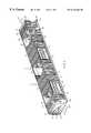
- FIG. 1is a top perspective view of a preferred embodiment of the module of the present invention, with parts of the passenger-side side wall and roof cut away;
- FIG. 2is a bottom perspective view of the module of FIG. 1;
- FIG. 3is a left side view of the module of FIG. 1, shown with three vehicles loaded therein;
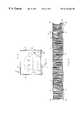
- FIG. 4is a section taken at line 4 — 4 of FIG. 3;
- FIG. 5is a section taken at line 5 — 5 of FIG. 3;
- FIG. 6is a right side view of the module of FIG. 1 .
- the present inventionis a module 10 for receiving and transporting motorized vehicles 12 (FIG. 3 ).
- the module 10is generally rectangular in cross-section, and includes a driver-side side wall 14 and a passenger-side side wall 16 that extends parallel to, and is laterally spaced apart from, the driver-side side wall 14 .
- the steering wheel and the driver of the vehicles 12have been assumed to be on the left hand side of each vehicle 12 .
- the module 10 of the present inventioncan be easily modified to accommodate vehicles where the steering wheel is located on the right hand side of the vehicle by changing the orientation of several components of the module 10 in a manner that would be readily apparent to one skilled in the art.
- a bottom support structureextends between the side walls 14 , 16 and supports the vehicles 12 that are received in the module 10 .
- the bottom support structure 18includes a pair of longitudinally extending wheel pans 20 , 22 for receiving the wheels of a vehicle 12 .
- a walkway 24extends parallel to the wheel pans 20 , 22 , and is located adjacent the driver-side side wall 14 to provide a surface for a worker to walk upon when the module 10 is empty.
- a plurality of laterally extending crossbeams 26support the wheel pans 20 , 22 and the walkway 24 .
- the module 10includes an angled ramp or inclined surface 30 that extends from the bottom 32 of the module 10 to the bottom support structure 18 such that vehicles 12 can be driven up the ramp 30 and into the wheel pans 20 , 22 of the bottom support structure 18 .
- the ramp 30preferably extends from the driver-side side wall 14 to the passenger-side side wall 16 .
- the ramp 30is preferably integral with the module 10 and is completely internal to the module 10 ; that is, the ramp 30 does not extend in the longitudinal direction beyond the side walls 14 , 16 . Because the ramp 30 does not extend beyond the side walls 14 , 16 , space in the module 10 in the longitudinal direction is conserved.
- the lip 36 at the bottom of the ramp 30(FIG. 1) is relatively small (i.e. preferably about 11 ⁇ 2′′ high) so that a vehicle 12 can be easily driven over the lip 36 .
- the module 10also includes an end wall 38 that encloses the forward end of the module 10 .
- the module 10includes an enclosure 40 having a generally rectangular cross section and a central space 42 for receiving the vehicles 12 .
- a roof 44extends between the side walls 14 , 16 and parallel to the bottom support structure 18 .
- the roof 44 and bottom support structure 18are spaced apart a distance to closely receive a vehicle 12 therebetween to minimize the wasted vertical space in the module 10 .
- the side walls 14 , 16are spaced apart a distance to minimize the wasted space in a lateral direction, while still providing sufficient space between the side walls 14 , 16 to accommodate the walkway 24 .
- the wheel pans 20 , 22are offset from a longitudinally extending center line A of the module 10 (FIG. 4) toward the passenger-side side wall 16 .
- the driver-side wheel pan 20is relatively narrow compared to the passenger-side wheel pan 22 .
- the relatively narrow width of the driver-side wheel pan 20serves to locate the vehicle 12 in the desired lateral position within the module 10 , and the extra width of the passenger-side wheel pan 22 accommodates vehicles 12 of varying widths. In this manner, the driver guides the driver-side wheel of each vehicle 12 into the driver-side wheel pan 20 , and does not have to worry about the location of the passenger-side wheels 22 .
- the module 10has a length that is selected to closely receive a predetermined number of vehicles 12 to minimize wasted space in the longitudinal direction. In the illustrated embodiment, the module 10 is sized to receive three vehicles 12 .
- the height of the module 10is selected such that the vertically unutilized space is minimized.
- the distance between the roof of a vehicle received in the module and the roof 44 of the moduleis less than 1 foot. This distance has been found to provide adequate clearance such that the vehicles do not contact the roof 44 when the vehicles are driven into the module 10 , or when bumps or jolts are applied to the module 10 during transportation of the module.
- the 1 foot distanceis also small enough to minimize wasted space in the vertical direction. If the height of the module is less than 8 feet, the desired clearance can be provided for most vehicles.
- the space between the roof of the vehicle and the roof of the moduleis less than about 1 ⁇ 3 of the height of the vehicle. Further alternately, the distance between the roof of the vehicle and the roof 44 of the module is less than about 1 ⁇ 5 of the height of the module.
- the sides walls 14 , 16 , end wall 38 and roof 44are preferably all made from corrugated metal or other materials suitable to provide the necessary structural strength and protection.
- the module 10includes a skeletal framework 43 of square tubular sections at the top of the module 10 and formed channels at the bottom of the module.
- the driver-side side wall 14preferably includes a plurality of openings that correspond to the driver-side door of each vehicle received in the module 10 .
- the driver-side side wall 14includes three openings 60 , 62 , 64 .
- the driver-side side wall 14includes a plurality of corrugated side panels 50 that extend approximately half the distance from the roof 44 to the bottom support structure 18 .
- the bottom openings 52 underneath the side panelsenable workers to place and remove wheel chocks (not shown) in the wheel pans 20 , 22 to secure the vehicles 12 in place from outside the module 10 .
- the driver-side side wall 14includes a forward truss 54 and a rearward truss 56 to provide support.
- the panels 50may alternately extend the full distance from the roof 44 to the bottom support structure 18 , in which case the wheel chocks can be located by a worker who is inside the module 10 .
- the module 10is preferably sized to closely receive a plurality of vehicles therein.
- the module 10is sized to receive three vehicles and is about 53′ long.
- each of the side openings 60 , 62 , 64is approximately 5′ in width and approximately 6′4′′ in height.
- the opening 60is spaced approximately 9′10′′ on center from the end wall 38 of the module 10
- the opening 62is located approximately at the center of the module 10 along its length
- the opening 64is spaced about 9′10′′ from the rear end of the module 10 .
- the module 10is one of two different heights: 6′ high for vehicles 59′′ and below in height and 7′6′′ for vehicles from 59′′ to 78.5′′ in height.
- the module 10is preferably about 8′ to about 8′6′′ in width (i.e. the external dimension of the module 10 in the lateral direction).
- the module 10 of the present inventionis preferably loaded with vehicles 12 as follows.
- the module 10is placed flat onto an external surface 66 (FIG. 3 ), such as a loading dock, driveway, or the like.
- an external surface 66such as a loading dock, driveway, or the like.
- the angled ramp 30extends from the external surface 66 to the bottom support surface 18 of the module 10 such that vehicles 12 can be driven up the ramp 30 and into the wheel pans 20 , 22 of the bottom support structure 18 . Because the vehicles 12 may be driven into the module, the vehicles can be quickly and easily loaded into the module 10 without the aid of an external ramp.
- a first vehicle 69is driven up the ramp 30 and onto the wheel pans 20 , 22 , and the first vehicle 69 is then driven through the length of the module 10 until the front driver-side door 68 of the first vehicle 69 coincides with the opening 64 .
- the driverthen opens the door 68 into the opening 64 , exits the first vehicle 69 , and closes the door 68 .
- the driverthen may exit the module through the opening 64 .
- the opening 64provides an exit path from the module 10 for the driver. When the driver exits through the opening 64 , this helps to minimize any further damage that may be imparted to the vehicle when the driver walks alongside the first vehicle 69 .
- keys, tools, or other items that the driver may carry, or a belt buckle or other metallic clothing items on the drivermay damage the vehicle as the driver walks alongside the first vehicle 69 .
- the openings 60 , 62 , 64also provide a point of entry into the module 10 to minimize driver-induced damage.
- the driver or another workerplaces wheel chocks (not shown) in front of the front driver-side wheel, and behind the rear driver-side wheel of the first vehicle 69 to secure the first vehicle 69 in the module 10 .
- the wheel chocks or other securementscan be placed in position by reaching through the bottom openings 52 . This enables a worker to place the wheel chocks from outside the module 10 , which minimizes contact with the vehicles 12 .
- a second vehicle 71is driven into the module 10 in a similar manner such that the front driver-side door 70 of the second vehicle 71 coincides with the opening 62 .
- the driverthen exits through the opening 62 and secures the second vehicle 71 with wheel chocks.
- a third vehicle 73may be driven into the module 10 such that the driver-side door 72 of the third vehicle 73 coincides with the opening 60 .
- the driverthen preferably exits through the opening 60 and secures the third vehicle 73 in place.
- each module 10preferably includes a set of upper corner castings 78 and a set of lower corner castings 80 for receiving twist locks (not shown) therein.
- the twist lockshelp to secure the vertically-stacked modules to each other at their corner castings.
- the lower corner castings 80may also be used to secure the front end of the module 10 to a chassis by receiving lock pins therein.
- the module 10further preferably includes a set of intermediate upper castings 82 and intermediate lower castings 84 .
- the intermediate upper castings 82are preferably longitudinally spaced about 40′ apart such that the module 10 can be lifted by a standard ISO (“International Standards Organization”) spreader that fits into the intermediate upper castings 82 .
- the intermediate upper castings 82can also be used to lock the module 10 (through the use of twists locks) to a standard container that is stacked on top of the module 10 .
- the intermediate lower castings 84are also preferably spaced apart about 40′ , and can be used to lock the module 10 onto a standard 40′ long container when the module 10 is stacked onto a standard container (not shown).
- the standard containermay be located in the well of the rail car, and the module 10 stacked on top of the standard container and secured to the standard container by twist locks passed through the lower intermediate castings 84 and the corner castings of the standard container.
- Each of the castings 78 , 80 , 82 , 84preferably includes side apertures 90 such that lashings can be passed through the side apertures 90 to secure the module 10 .
- the side apertures 90also provide a surface for receiving the hook of a loading machine to load or move the module 10 .
- One embodiment of the twist locks that can be used with the corner castings 78 , 80 , 82 , 84are model C 5 AM-DF double cone semi-automatic twist locks manufactured by Buffers USA of Jacksonville, Fla.
- One embodiment of the corner casting 78 , 80 , 82 , 84may also be obtained from Buffers USA and are ISO type corner castings that are modified for the extra width of the module 10 .
- the module 10includes a standard-sized cutout, or tunnel 92 , in its bottom support structure 18 , as best shown in FIG. 2 .
- the tunnel 92is shaped to receive the gooseneck of the chassis to help lock the module 10 into position on the chassis.
- the outermost modulesare preferably arranged such that the passenger-side side wall 16 of each module faces outward and the openings 60 , 62 , 64 of each module face inwardly. Because the passenger-side side wall 16 lacks the openings 60 , 62 , 64 , it provides greater protection from the elements, such as sea spray or rain.
- the openings 60 , 62 , 64face each other and the passenger-side side walls 16 are located around the outer perimeter of the two modules.
- multiple modulesare stacked side-by-side, they are preferably arranged such that the driver-side side walls 14 of the end modules face inwardly.
- a standard containermay be located adjacent the driver-side side wall 16 of a module to cover the opening 60 , 62 , 64 and protect the vehicles in the module 10 .
- a tarpmay be used to cover the opening 60 , 62 , 64 .
Landscapes
- Engineering & Computer Science (AREA)
- Mechanical Engineering (AREA)
- Fittings On The Vehicle Exterior For Carrying Loads, And Devices For Holding Or Mounting Articles (AREA)
- Body Structure For Vehicles (AREA)
- Packaging Of Machine Parts And Wound Products (AREA)
Abstract
Description
Claims (26)
Priority Applications (4)
| Application Number | Priority Date | Filing Date | Title |
|---|---|---|---|
| US09/364,910US6416264B2 (en) | 1998-07-30 | 1999-07-28 | Vehicle transportation module |
| US09/793,022US6503034B2 (en) | 1998-07-30 | 2001-02-26 | Vehicle transportation module |
| US09/885,663US6893205B2 (en) | 1998-07-30 | 2001-06-20 | Vehicle transportation module |
| US10/286,325US6890136B2 (en) | 1998-07-30 | 2002-11-01 | Vehicle transportation module |
Applications Claiming Priority (2)
| Application Number | Priority Date | Filing Date | Title |
|---|---|---|---|
| US9460198P | 1998-07-30 | 1998-07-30 | |
| US09/364,910US6416264B2 (en) | 1998-07-30 | 1999-07-28 | Vehicle transportation module |
Related Child Applications (2)
| Application Number | Title | Priority Date | Filing Date |
|---|---|---|---|
| US09/793,022DivisionUS6503034B2 (en) | 1998-07-30 | 2001-02-26 | Vehicle transportation module |
| US09/885,663Continuation-In-PartUS6893205B2 (en) | 1998-07-30 | 2001-06-20 | Vehicle transportation module |
Publications (2)
| Publication Number | Publication Date |
|---|---|
| US20010043843A1 US20010043843A1 (en) | 2001-11-22 |
| US6416264B2true US6416264B2 (en) | 2002-07-09 |
Family
ID=26789063
Family Applications (3)
| Application Number | Title | Priority Date | Filing Date |
|---|---|---|---|
| US09/364,910Expired - LifetimeUS6416264B2 (en) | 1998-07-30 | 1999-07-28 | Vehicle transportation module |
| US09/793,022Expired - LifetimeUS6503034B2 (en) | 1998-07-30 | 2001-02-26 | Vehicle transportation module |
| US10/286,325Expired - LifetimeUS6890136B2 (en) | 1998-07-30 | 2002-11-01 | Vehicle transportation module |
Family Applications After (2)
| Application Number | Title | Priority Date | Filing Date |
|---|---|---|---|
| US09/793,022Expired - LifetimeUS6503034B2 (en) | 1998-07-30 | 2001-02-26 | Vehicle transportation module |
| US10/286,325Expired - LifetimeUS6890136B2 (en) | 1998-07-30 | 2002-11-01 | Vehicle transportation module |
Country Status (1)
| Country | Link |
|---|---|
| US (3) | US6416264B2 (en) |
Cited By (5)
| Publication number | Priority date | Publication date | Assignee | Title |
|---|---|---|---|---|
| US6890136B2 (en) | 1998-07-30 | 2005-05-10 | Trailer Bridge, Inc. | Vehicle transportation module |
| US6893205B2 (en)* | 1998-07-30 | 2005-05-17 | Trailer Bridge, Inc. | Vehicle transportation module |
| US7341422B1 (en) | 1998-04-08 | 2008-03-11 | Trailer Bridge, Inc. | Container transportation system and method |
| US20110014003A1 (en)* | 2009-07-17 | 2011-01-20 | International Truck Intellectual Property Company, Llc | Stackable Armored Vehicle |
| US9884575B2 (en)* | 2016-05-25 | 2018-02-06 | Dropstor, Inc. | Container having a spring-counter-balanced ramp wall |
Families Citing this family (6)
| Publication number | Priority date | Publication date | Assignee | Title |
|---|---|---|---|---|
| DE10015097A1 (en)* | 2000-03-28 | 2001-10-04 | Giesecke & Devrient Gmbh | Banknote paper and method for its printing, engraved printing plate for such a method and method for producing an engraved print- plate for use with such printing, to produce complex print images that are hard to counterfeit |
| US6878069B2 (en)* | 2003-06-05 | 2005-04-12 | Sps Technologies, Inc. | Helical groove fasteners and methods for making same |
| US20050242341A1 (en)* | 2003-10-09 | 2005-11-03 | Knudson Christopher T | Apparatus and method for supporting a flexible substrate during processing |
| US20110083579A1 (en)* | 2009-10-14 | 2011-04-14 | John Williams | Railcars for personal vehicles systems |
| DE102015000159B4 (en)* | 2015-01-05 | 2019-07-25 | Johannes March | Construction and use of semi-high 40 'containers open top loading and closed with a fixed steel roof to replace standard 20' containers and maritime transport innovation to maximum standardization to 40 'standard |
| CA3139230A1 (en) | 2021-11-16 | 2023-05-16 | 1332006 Alberta Inc. | Expandable vehicle container |
Citations (32)
| Publication number | Priority date | Publication date | Assignee | Title |
|---|---|---|---|---|
| US1247553A (en) | 1917-03-16 | 1917-11-20 | William Linquist | Freight-car construction. |
| US1290818A (en) | 1917-10-20 | 1919-01-07 | Dodge Brothers | Automobile-shipping device. |
| US2022376A (en) | 1935-02-18 | 1935-11-26 | Whitehead & Kales Co | Means for transporting vehicles and the like |
| US2492980A (en)* | 1947-03-10 | 1950-01-03 | Edward V Garnett | Trailer for transporting automobiles |
| US2521088A (en)* | 1946-08-16 | 1950-09-05 | Phelps Donald | Shipping container and method of transporting vehicles |
| US2587456A (en)* | 1949-03-28 | 1952-02-26 | Lynn M Francis | Convertible automobile and general freight carrying trailer |
| CA527696A (en) | 1956-07-10 | V. Garnett Edward | Carrier for transporting automobiles | |
| US3110361A (en) | 1962-08-29 | 1963-11-12 | Hirsch Leo | Wheel chock apparatus for carrying motor cars |
| US3180283A (en)* | 1961-09-25 | 1965-04-27 | Dana Corp | Multi-level transport structure |
| US3646609A (en)* | 1969-06-06 | 1972-02-29 | Sea Land Service | Container for handling freight |
| US3709155A (en)* | 1971-03-22 | 1973-01-09 | Pullman Inc | Automobile hold-down device |
| US4759668A (en)* | 1986-12-30 | 1988-07-26 | Larsen Stuart A | Method and apparatus to enhance intermodal containers for cargo transport |
| US4911590A (en)* | 1988-05-25 | 1990-03-27 | American President Companies, Ltd. | Automobile loading rack and method for loading into containers |
| US4963067A (en) | 1986-12-18 | 1990-10-16 | G & G Intellectual Properties, Inc. | System for loading and transporting wheeled vehicles |
| US5032044A (en) | 1990-04-24 | 1991-07-16 | Southern Pacific Transportation Company | Light weight stowable front wheel seats for hauling large semistacked highway trucks in railroad cars of extraordinary height |
| US5037255A (en) | 1990-02-26 | 1991-08-06 | Standard Car Truck Company | Wheel chock for a motor vehicle container |
| US5044866A (en)* | 1987-04-27 | 1991-09-03 | Commodity Handling Systems, Inc. | Containerizing and decontainerizing a load |
| US5106246A (en)* | 1989-04-04 | 1992-04-21 | Chance Martin D | Movable platform for storing freight and automobiles |
| US5114202A (en) | 1991-04-05 | 1992-05-19 | Johnson Richard D | Multipurpose trailer |
| US5213458A (en)* | 1990-07-27 | 1993-05-25 | Sea-Land Corporation, Inc. | Method and apparatus for containerized shipment of automobiles |
| US5413224A (en)* | 1993-07-23 | 1995-05-09 | Ply Mar Inc. | Stackable pallet packaging |
| US5427485A (en)* | 1994-02-23 | 1995-06-27 | Henderson; John W. B. | Pivoting movable ramp for transporting vehicles |
| US5525026A (en)* | 1993-03-05 | 1996-06-11 | Demonte Fab, Ltd. | Palletizer trailer and storage container |
| US5526940A (en)* | 1994-05-19 | 1996-06-18 | Sea Barge, Inc. | Multilevel container for transporting automobiles |
| US5584527A (en)* | 1994-09-21 | 1996-12-17 | Oshkosh Truck Corporation | Lightweight trailer with integral plate seams |
| US5669745A (en) | 1995-08-30 | 1997-09-23 | Zeftek, Inc. | Bumper system for an intermodal auto trailer |
| US5730578A (en) | 1995-02-15 | 1998-03-24 | Wabash National Corporation | Lifting mechanism for a deck system |
| US5743689A (en) | 1996-02-20 | 1998-04-28 | Schlaeger; Gary D. | Automobile loading wedge and method |
| US5797712A (en)* | 1993-12-28 | 1998-08-25 | G & G Intellectual Properties, Inc. | Automobile transporting system including insertable tilt-up rack |
| US5816423A (en)* | 1993-10-25 | 1998-10-06 | Stoughton Trailers, Inc. | Intermodal container |
| US5853280A (en)* | 1994-09-23 | 1998-12-29 | Lohr Industrie | Semitrailer for vehicle transporation with removable upper platform |
| US6010285A (en)* | 1997-10-03 | 2000-01-04 | Kar-Tainer International, Inc. | Collapsible vehicle transportation frame |
Family Cites Families (10)
| Publication number | Priority date | Publication date | Assignee | Title |
|---|---|---|---|---|
| US3934740A (en) | 1973-10-29 | 1976-01-27 | Rumell James A | Transport vehicle with tiltable chassis |
| US4343401A (en) | 1980-03-31 | 1982-08-10 | United States Lines, Inc. | Automobile containerized shipment support kit |
| US4875821A (en) | 1986-07-01 | 1989-10-24 | Oren David D | Front end loading enclosed semi trailer |
| JPH041118Y2 (en) | 1986-07-31 | 1992-01-14 | ||
| WO1990011911A1 (en) | 1989-04-04 | 1990-10-18 | Ramp International East Coast Us, Inc. | Apparatus for storing automobiles inside maritime containers |
| US5051046A (en) | 1989-12-14 | 1991-09-24 | Transportation Concepts, Inc. | Semi trailer convertible for hauling automobiles |
| US5286149A (en) | 1993-02-16 | 1994-02-15 | Seay Michael W | Apparatus for supporting a vehicle inside a cargo container |
| US5344266A (en) | 1993-04-16 | 1994-09-06 | Kolb Peter W | Fully adjustable storage device for loading and transporting vehicles in containers |
| US5775858A (en) | 1995-12-01 | 1998-07-07 | Vehicle Transport, Inc. | Storage assembly for loading and transporting vehicles in a container |
| US6416264B2 (en) | 1998-07-30 | 2002-07-09 | Trailer Bridge, Inc. | Vehicle transportation module |
- 1999
- 1999-07-28USUS09/364,910patent/US6416264B2/ennot_activeExpired - Lifetime
- 2001
- 2001-02-26USUS09/793,022patent/US6503034B2/ennot_activeExpired - Lifetime
- 2002
- 2002-11-01USUS10/286,325patent/US6890136B2/ennot_activeExpired - Lifetime
Patent Citations (32)
| Publication number | Priority date | Publication date | Assignee | Title |
|---|---|---|---|---|
| CA527696A (en) | 1956-07-10 | V. Garnett Edward | Carrier for transporting automobiles | |
| US1247553A (en) | 1917-03-16 | 1917-11-20 | William Linquist | Freight-car construction. |
| US1290818A (en) | 1917-10-20 | 1919-01-07 | Dodge Brothers | Automobile-shipping device. |
| US2022376A (en) | 1935-02-18 | 1935-11-26 | Whitehead & Kales Co | Means for transporting vehicles and the like |
| US2521088A (en)* | 1946-08-16 | 1950-09-05 | Phelps Donald | Shipping container and method of transporting vehicles |
| US2492980A (en)* | 1947-03-10 | 1950-01-03 | Edward V Garnett | Trailer for transporting automobiles |
| US2587456A (en)* | 1949-03-28 | 1952-02-26 | Lynn M Francis | Convertible automobile and general freight carrying trailer |
| US3180283A (en)* | 1961-09-25 | 1965-04-27 | Dana Corp | Multi-level transport structure |
| US3110361A (en) | 1962-08-29 | 1963-11-12 | Hirsch Leo | Wheel chock apparatus for carrying motor cars |
| US3646609A (en)* | 1969-06-06 | 1972-02-29 | Sea Land Service | Container for handling freight |
| US3709155A (en)* | 1971-03-22 | 1973-01-09 | Pullman Inc | Automobile hold-down device |
| US4963067A (en) | 1986-12-18 | 1990-10-16 | G & G Intellectual Properties, Inc. | System for loading and transporting wheeled vehicles |
| US4759668A (en)* | 1986-12-30 | 1988-07-26 | Larsen Stuart A | Method and apparatus to enhance intermodal containers for cargo transport |
| US5044866A (en)* | 1987-04-27 | 1991-09-03 | Commodity Handling Systems, Inc. | Containerizing and decontainerizing a load |
| US4911590A (en)* | 1988-05-25 | 1990-03-27 | American President Companies, Ltd. | Automobile loading rack and method for loading into containers |
| US5106246A (en)* | 1989-04-04 | 1992-04-21 | Chance Martin D | Movable platform for storing freight and automobiles |
| US5037255A (en) | 1990-02-26 | 1991-08-06 | Standard Car Truck Company | Wheel chock for a motor vehicle container |
| US5032044A (en) | 1990-04-24 | 1991-07-16 | Southern Pacific Transportation Company | Light weight stowable front wheel seats for hauling large semistacked highway trucks in railroad cars of extraordinary height |
| US5213458A (en)* | 1990-07-27 | 1993-05-25 | Sea-Land Corporation, Inc. | Method and apparatus for containerized shipment of automobiles |
| US5114202A (en) | 1991-04-05 | 1992-05-19 | Johnson Richard D | Multipurpose trailer |
| US5525026A (en)* | 1993-03-05 | 1996-06-11 | Demonte Fab, Ltd. | Palletizer trailer and storage container |
| US5413224A (en)* | 1993-07-23 | 1995-05-09 | Ply Mar Inc. | Stackable pallet packaging |
| US5816423A (en)* | 1993-10-25 | 1998-10-06 | Stoughton Trailers, Inc. | Intermodal container |
| US5797712A (en)* | 1993-12-28 | 1998-08-25 | G & G Intellectual Properties, Inc. | Automobile transporting system including insertable tilt-up rack |
| US5427485A (en)* | 1994-02-23 | 1995-06-27 | Henderson; John W. B. | Pivoting movable ramp for transporting vehicles |
| US5526940A (en)* | 1994-05-19 | 1996-06-18 | Sea Barge, Inc. | Multilevel container for transporting automobiles |
| US5584527A (en)* | 1994-09-21 | 1996-12-17 | Oshkosh Truck Corporation | Lightweight trailer with integral plate seams |
| US5853280A (en)* | 1994-09-23 | 1998-12-29 | Lohr Industrie | Semitrailer for vehicle transporation with removable upper platform |
| US5730578A (en) | 1995-02-15 | 1998-03-24 | Wabash National Corporation | Lifting mechanism for a deck system |
| US5669745A (en) | 1995-08-30 | 1997-09-23 | Zeftek, Inc. | Bumper system for an intermodal auto trailer |
| US5743689A (en) | 1996-02-20 | 1998-04-28 | Schlaeger; Gary D. | Automobile loading wedge and method |
| US6010285A (en)* | 1997-10-03 | 2000-01-04 | Kar-Tainer International, Inc. | Collapsible vehicle transportation frame |
Cited By (8)
| Publication number | Priority date | Publication date | Assignee | Title |
|---|---|---|---|---|
| US7341422B1 (en) | 1998-04-08 | 2008-03-11 | Trailer Bridge, Inc. | Container transportation system and method |
| US20080107505A1 (en)* | 1998-04-08 | 2008-05-08 | Trailer Bridge, Inc. | Container transportation system and method |
| US6890136B2 (en) | 1998-07-30 | 2005-05-10 | Trailer Bridge, Inc. | Vehicle transportation module |
| US6893205B2 (en)* | 1998-07-30 | 2005-05-17 | Trailer Bridge, Inc. | Vehicle transportation module |
| US20110014003A1 (en)* | 2009-07-17 | 2011-01-20 | International Truck Intellectual Property Company, Llc | Stackable Armored Vehicle |
| US8057138B2 (en)* | 2009-07-17 | 2011-11-15 | International Truck Intellectual Property Company, Llc | Stackable armored vehicle |
| US8231315B2 (en)* | 2009-07-17 | 2012-07-31 | International Truck Intellectual Property Company, Llc | Stackable armored vehicle |
| US9884575B2 (en)* | 2016-05-25 | 2018-02-06 | Dropstor, Inc. | Container having a spring-counter-balanced ramp wall |
Also Published As
| Publication number | Publication date |
|---|---|
| US6503034B2 (en) | 2003-01-07 |
| US20030095844A1 (en) | 2003-05-22 |
| US6890136B2 (en) | 2005-05-10 |
| US20010043843A1 (en) | 2001-11-22 |
| US20020127076A1 (en) | 2002-09-12 |
Similar Documents
| Publication | Publication Date | Title |
|---|---|---|
| SU1407393A3 (en) | Container for shipment in railway car | |
| US5816423A (en) | Intermodal container | |
| CA2116515C (en) | Palletizer trailer and storage container | |
| US5255806A (en) | Reinforced plastic composite intermodal vehicle hauler | |
| US6390742B1 (en) | Locking cone chassis | |
| US6893205B2 (en) | Vehicle transportation module | |
| US6416264B2 (en) | Vehicle transportation module | |
| US5183375A (en) | Container stacking apparatus | |
| US20040028495A1 (en) | Transport linking frames | |
| CA2563265C (en) | Transport platform | |
| US7140821B2 (en) | Roll on/roll off ramp-deck transport platform | |
| US4592585A (en) | Semitrailer and method of loading the same | |
| HU215300B (en) | Vehicle with superstructure especially for transporting packages | |
| US4685720A (en) | Semitrailer and method of loading the same | |
| EP1427604B1 (en) | Intermodal transport system for freight | |
| US20050109255A1 (en) | Barge construction and freight hauling system | |
| PL196184B1 (en) | Vehicle with loading boxes for receiving loads | |
| WO2009093893A1 (en) | Transport container, method for stacking containers, and kit of containers and roofs | |
| WO2017064449A1 (en) | Vehicle shipping crate and method of loading vehicles into a ship | |
| JPS61115744A (en) | Method of transportation of passenger car | |
| KR200427799Y1 (en) | Passenger Car Container | |
| US11214436B2 (en) | Transport platform | |
| EP1343704B1 (en) | System for loading and unloading of vehicles | |
| US3833139A (en) | Cargo transporting and handling vehicle | |
| RU2081764C1 (en) | Method of and container for transportation of light-weight loads |
Legal Events
| Date | Code | Title | Description |
|---|---|---|---|
| AS | Assignment | Owner name:TRAILER BRIDGE, INC., FLORIDA Free format text:INVALID RECORDING.;ASSIGNORS:HEIM, RALPH W.;MORLEY, J. EDWARD;SHAHANI, P.W.;REEL/FRAME:010219/0442;SIGNING DATES FROM 19990726 TO 19990727 Owner name:TRAILER BRIDGE, INC., FLORIDA Free format text:(ASSIGNMENT OF ASSIGNOR'S INTEREST) RE-RECORD TO CORRECT THE NUMBER OF MICROFILM PAGES FROM 2 TO 3 AT REEL 010219, FRAME 0442 AND TO ADD ASSIGNOR'S SIGNATURE.;ASSIGNORS:HEIM, RALPH W.;MORLEY, J. EDWARD;SHAHANI, P. W.;REEL/FRAME:010387/0488;SIGNING DATES FROM 19990726 TO 19990727 | |
| STCF | Information on status: patent grant | Free format text:PATENTED CASE | |
| AS | Assignment | Owner name:CONGRESS FINANCIAL CORPORATION, FLORIDA Free format text:ASSIGNMENT OF ASSIGNORS INTEREST;ASSIGNOR:TRAILER BRIDGE, INC.;REEL/FRAME:015259/0162 Effective date:20040423 Owner name:CONGRESS FINANCIAL CORPORATION, FLORIDA Free format text:SECURITY AGREEMENT;ASSIGNOR:TRAILER BRIDGE, INC.;REEL/FRAME:015259/0162 Effective date:20040423 | |
| FPAY | Fee payment | Year of fee payment:4 | |
| FPAY | Fee payment | Year of fee payment:8 | |
| AS | Assignment | Owner name:TRAILER BRIDGE, INC., FLORIDA Free format text:RELEASE BY SECURED PARTY;ASSIGNOR:WELLS FARGO BANK, NATIONAL ASSOCIATION (SUCCESSOR BY MERGER TO WACHOVIA BANK, NA, SUCCESSOR BY MERGER TO CONGRESS FINANCIAL CORPORATION);REEL/FRAME:027970/0057 Effective date:20120402 Owner name:U.S. BANK NATIONAL ASSOCIATION, MASSACHUSETTS Free format text:SECURITY AGREEMENT;ASSIGNOR:TRAILER BRIDGE, INC.;REEL/FRAME:027971/0500 Effective date:20120402 Owner name:GLEACHER PRODUCTS CORP., NEW YORK Free format text:SECURITY AGREEMENT;ASSIGNOR:TRAILER BRIDGE, INC.;REEL/FRAME:027970/0477 Effective date:20120402 | |
| FPAY | Fee payment | Year of fee payment:12 | |
| AS | Assignment | Owner name:TRAILER BRIDGE, INC., FLORIDA Free format text:RELEASE BY SECURED PARTY;ASSIGNOR:CORTLAND PRODUCTS CORP., AS AGENT F/K/A GLEACHER PRODUCTS CORP.;REEL/FRAME:044315/0583 Effective date:20171121 | |
| AS | Assignment | Owner name:WELLS FARGO BANK, NATIONAL ASSOCIATION, GEORGIA Free format text:SECURITY INTEREST;ASSIGNOR:TRAILER BRIDGE, INC.;REEL/FRAME:069956/0730 Effective date:20250121 |