US6416169B1 - Micromachined fluid ejector systems and methods having improved response characteristics - Google Patents
Micromachined fluid ejector systems and methods having improved response characteristicsDownload PDFInfo
- Publication number
- US6416169B1 US6416169B1US09/718,420US71842000AUS6416169B1US 6416169 B1US6416169 B1US 6416169B1US 71842000 AUS71842000 AUS 71842000AUS 6416169 B1US6416169 B1US 6416169B1
- Authority
- US
- United States
- Prior art keywords
- fluid
- faceplate
- piston
- chamber
- cylinder structure
- Prior art date
- Legal status (The legal status is an assumption and is not a legal conclusion. Google has not performed a legal analysis and makes no representation as to the accuracy of the status listed.)
- Expired - Lifetime
Links
- 239000012530fluidSubstances0.000titleclaimsabstractdescription142
- 238000000034methodMethods0.000titleclaimsdescription35
- 230000004044responseEffects0.000titledescription2
- 239000000758substrateSubstances0.000claimsdescription7
- 239000007788liquidSubstances0.000claimsdescription2
- 238000006073displacement reactionMethods0.000abstractdescription3
- 230000005684electric fieldEffects0.000description11
- 238000007639printingMethods0.000description8
- 238000013459approachMethods0.000description7
- 230000008569processEffects0.000description6
- 230000008901benefitEffects0.000description3
- 238000007641inkjet printingMethods0.000description3
- 230000004048modificationEffects0.000description3
- 238000012986modificationMethods0.000description3
- XLYOFNOQVPJJNP-UHFFFAOYSA-NwaterSubstancesOXLYOFNOQVPJJNP-UHFFFAOYSA-N0.000description3
- 230000002730additional effectEffects0.000description2
- 230000001419dependent effectEffects0.000description2
- 238000000151depositionMethods0.000description2
- 239000003814drugSubstances0.000description2
- 229940079593drugDrugs0.000description2
- 238000004519manufacturing processMethods0.000description2
- 108091028043Nucleic acid sequenceProteins0.000description1
- 241000321453Paranthias colonusSpecies0.000description1
- 238000004458analytical methodMethods0.000description1
- 230000004888barrier functionEffects0.000description1
- 239000012620biological materialSubstances0.000description1
- 239000012472biological sampleSubstances0.000description1
- 230000015572biosynthetic processEffects0.000description1
- 239000003990capacitorSubstances0.000description1
- 230000015556catabolic processEffects0.000description1
- 238000006243chemical reactionMethods0.000description1
- 230000007423decreaseEffects0.000description1
- 230000000694effectsEffects0.000description1
- 230000005686electrostatic fieldEffects0.000description1
- 238000005516engineering processMethods0.000description1
- 230000005669field effectEffects0.000description1
- 238000010438heat treatmentMethods0.000description1
- 230000003993interactionEffects0.000description1
- 239000000463materialSubstances0.000description1
- 238000005459micromachiningMethods0.000description1
- 229920002120photoresistant polymerPolymers0.000description1
- 229920003023plasticPolymers0.000description1
- 239000004033plasticSubstances0.000description1
- 239000004065semiconductorSubstances0.000description1
- 239000000126substanceSubstances0.000description1
Images


Classifications
- B—PERFORMING OPERATIONS; TRANSPORTING
- B41—PRINTING; LINING MACHINES; TYPEWRITERS; STAMPS
- B41J—TYPEWRITERS; SELECTIVE PRINTING MECHANISMS, i.e. MECHANISMS PRINTING OTHERWISE THAN FROM A FORME; CORRECTION OF TYPOGRAPHICAL ERRORS
- B41J2/00—Typewriters or selective printing mechanisms characterised by the printing or marking process for which they are designed
- B41J2/005—Typewriters or selective printing mechanisms characterised by the printing or marking process for which they are designed characterised by bringing liquid or particles selectively into contact with a printing material
- B41J2/01—Ink jet
- B41J2/135—Nozzles
- B41J2/14—Structure thereof only for on-demand ink jet heads
- B—PERFORMING OPERATIONS; TRANSPORTING
- B41—PRINTING; LINING MACHINES; TYPEWRITERS; STAMPS
- B41J—TYPEWRITERS; SELECTIVE PRINTING MECHANISMS, i.e. MECHANISMS PRINTING OTHERWISE THAN FROM A FORME; CORRECTION OF TYPOGRAPHICAL ERRORS
- B41J2/00—Typewriters or selective printing mechanisms characterised by the printing or marking process for which they are designed
- B41J2/005—Typewriters or selective printing mechanisms characterised by the printing or marking process for which they are designed characterised by bringing liquid or particles selectively into contact with a printing material
- B41J2/01—Ink jet
- B41J2/015—Ink jet characterised by the jet generation process
- B41J2/04—Ink jet characterised by the jet generation process generating single droplets or particles on demand
- B41J2002/043—Electrostatic transducer
Definitions
- This present inventionrelates to micromachined or microelectromechanical system (MEMS) based fluid ejectors.
- MEMSmicroelectromechanical system
- Fluid ejectorshave been developed for ink jet recording or printing.
- Ink jet printing systemsoffer numerous benefits, including extremely quiet operation when printing, high speed printing, a high degree of freedom in ink selection, and the ability to use low-cost plain paper.
- the so-called “drop-on-demand” drive methodwhere ink is output only when required for printing, is now the conventional approach.
- the drop-on-demand drive methodmakes it unnecessary to recover ink not needed for printing.
- Fluid ejectors for ink jet printinginclude one or more nozzles which allow the formation and control of small ink droplets to permit high resolution, resulting in the ability to print sharper characters with improved tonal resolution.
- drop-on-demand ink jet print headsare generally used for high resolution printers.
- Drop-on-demand technologygenerally uses some type of pulse generator to form and eject drops.
- a chamber having an ink nozzlemay be fitted with a piezoelectric wall that is deformed when a voltage is applied.
- the fluidis forced out of the nozzle orifice as a drop.
- the dropthen impinges directly on an associated printing surface.
- a piezoelectric deviceas a driver is described in JP B-1990-51734.
- Another type of print headuses bubbles formed by heat pulses to force fluid out of the nozzle.
- the dropsare separated from the ink supply when the bubbles collapse.
- Use of pressure generated by heating the ink to generate bubblesis described in JP B-1986-59911.
- Yet another type of drop-on-demand print headincorporates an electrostatic actuator.
- This type of print headutilizes electrostatic force to eject the ink. Examples of such electrostatic print heads are disclosed in U.S. Pat. No. 4,520,375 to Kroll and Japanese Laid-Open Patent Publication No. 289351/90.
- the ink jet head disclosed in the 375 patentuses an electrostatic actuator comprising a diaphragm that constitutes a part of an ink ejection chamber and a base plate disposed outside of the ink ejection chamber opposite to the diaphragm.
- the ink jet headejects ink droplets through a nozzle communicating with the ink ejection chamber, by applying a time varying voltage between the diaphragm and the base plate.
- the diaphragm and the base platethus act as a capacitor, which causes the diaphragm to be set into mechanical motion and the fluid to exit responsive to the diaphragm's motion.
- the ink jet head discussed in the Japan 351distorts its diaphragm by applying a voltage to an electrostatic actuator fixed on the diaphragm. This result in suction of additional ink into an ink ejection chamber. Once the voltage is removed, the diaphragm is restored to its non-distorted condition, ejecting ink from the overfilled ink ejection chamber.
- Fluid drop ejectorsmay be used not only for printing, but also for depositing photoresist and other liquids in the semiconductor and flat panel display industries, for delivering drug and biological samples, for delivering multiple chemicals for chemical reactions, for handling DNA sequences, for delivering drugs and biological materials for interaction studies and assaying, and for depositing thin and narrow layers of plastics for usable as permanent and/or removable gaskets in micro-machines.
- This inventionprovides fluid ejection systems and methods having improved performance characteristics.
- This inventionseparately provides fluid ejection systems and methods having improved response to actuation signals and improved control.
- This inventionprovides fluid ejection systems and methods having improved efficiency.
- This inventionprovides fluid ejection systems and methods requiring lower voltage to eject the fluid.
- This inventionprovides fluid ejection systems and methods having increased drop generation rate.
- This inventionprovides fluid ejection systems and methods having increased drop ejection velocities.
- This inventionprovides fluid ejection systems and methods having reduced viscous fluid forces that oppose movement the actuator used to eject the fluid.
- This inventionprovides fluid ejection systems and methods where the viscous fluid forces opposing movement the actuator used to eject the fluid that vary substantially linearly with displacement of the actuator.
- This inventionprovides fluid ejection systems and methods where the viscous fluid forces opposing movement the actuator used to eject the fluid that prevent the actuator from contacting other structures of the ejector.
- This inventionprovides fluid ejection systems and methods having fluid ejectors with improved structural features.
- the fluid ejectors according to this inventioninclude an unsealed piston structure usable to eject fluid drops. In other various embodiments, the fluid ejectors according to this invention also include a cylinder structure. In still other various embodiments, the fluid ejectors according to this invention include a free space between the actuator and the faceplate that includes the nozzle hole.
- a micromachined fluid ejectorincludes a piston structure arranged to eject fluid drops.
- the piston structureis resiliently movably supported within a fluid chamber, such that movement of the piston ejects fluid.
- the fluid chamberis defined by a cylinder structure so that the piston structure moves within the cylinder structure.
- a free spaceis provided between the piston structure and a faceplate including a nozzle hole.
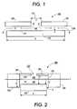
- FIG. 1is a cross-sectional view of a first exemplary embodiment of a fluid ejector according to this invention
- FIG. 2is a cross-sectional view of a second exemplary embodiment of a fluid ejector according to this invention.
- FIG. 3is a plot of the squeeze-film force F sq as the piston structure is moved towards the faceplate for the exemplary embodiments shown in FIGS. 1 and 2;
- FIG. 4is a cross-sectional view of the embodiment of FIG. 2 during movement of the piston towards the faceplate;
- FIG. 5is a top view of an alternative configuration of the exemplary embodiment shown in FIG. 2;
- FIG. 6is a cross-sectional view of the exemplary embodiment shown in FIG. 5 taken along line VI—VI.
- the fluid ejectors according to this inventionincludes electrostatically or magnetically driven piston structures whose movement ejects a relatively small amount of fluid, commonly referred to as a drop or droplet.
- the fluid ejectors according to this inventionmay be fabricated using the SUMMiT processes or other suitable micromachining processes.
- the SUMMiT processesare covered by various U.S. patents belonging to Sandia National Labs, including U.S. Pat. Nos. 5,783,340; 5,798,283; 5,804,084; 5,919,548; 5,963,788; and 6,053,208, each of which is incorporated herein by reference in its entirety.
- the SUMMiT processesare primarily covered by the '084 and '208 patents. In particular, the methods discussed in copending U.S. patent application Ser. No. 09/723,243, filed herewith and incorporated herein by reference in its entirety, may be used.
- electrostatic and magnetic forcesare particularly applicable.
- electrostatic or magnetic attraction of the piston structure to the faceplatemay be used to drive the piston structure.
- electrostatic or magnetic attraction of the piston structure to a baseplate on a side of the piston structure opposite the faceplatemay be used to displace the piston structure away from the faceplate.
- the piston structureis resiliently mounted so that a restoring force is generated to move the piston structure to its undisplaced position to eject a fluid drop.
- Another exemplary drive system suitable for this inventionis an electrostatic comb drive.
- movement of the piston structurecauses a portion of the fluid between the piston and the faceplate to be forced out of the nozzle hole in the faceplate, forming a drop or jet of fluid.
- viscous forcesthat are generated by the flow of the fluid along a working surface of the piston structure toward and away from the nozzle hole cause a force that resists the movement of the piston structure.
- Such resistance forcetends to slow the piston motion, and prevents the piston from contacting the faceplate.
- the fluid chamberis defined by a “cylinder” structure so that the piston structure moves within the “cylinder” structure.
- cylinderstructure
- the cylinder structure and the faceplatedefine the fluid chamber.
- the cylinder structure and the piston structureare designed to cooperate so that movement of the piston structure within the cylinder structure ejects fluid according to various design criteria.
- a free spaceis provided between the faceplate and the piston structure at its maximum displacement towards the faceplate.
- the cylinder structureextends from the faceplate so that a stroke of the piston structure within the cylinder structure will not allow the piston structure to enter the free space.
- the free spaceis designed to ameliorate the squeeze-film force.
- FIG. 1shows a first exemplary embodiment of an electrostatic microelectromechanical system (MEMS) based fluid ejector 100 according to this invention.
- the ejector 100comprises a movable piston structure 110 and a stationary faceplate 130 .
- a fluid chamber 120is defined between the piston structure 110 and the faceplate 130 .
- a fluid 140 to be ejectedis supplied in the fluid chamber 120 from a fluid reservoir (not shown).
- the faceplate 130includes a nozzle hole 132 through which a fluid jet or drop is ejected.
- the piston structure 110moves towards the faceplate 130 by electrostatic attraction between the piston structure 110 and the faceplate 130 .
- a portion of the fluid 140 between the piston structure 110 and the faceplate 130is forced out of the nozzle hole 132 , forming a jet or drop of the fluid.
- the dominant forcesare the electrostatic force that drives the piston structure 110 towards the faceplate 130 and the squeeze-film force F sq .
- the squeeze-film force F sqincreases faster than the electrostatic attractive force between the piston structure 110 and the faceplate 130 .
- the squeeze-film force F sqvaries inversely with the cube of the distance x (1/x 3 ) while the electrostatic force varies inversely with the square of the distance x (1/x 2 ). As the distance x becomes very small, such as, on the order of 1 micron, the squeeze-film force F sq becomes equal to or greater than the electrostatic force.
- the squeeze-film force F sqstops the movement of the piston structure 110 towards the faceplate 130 before the piston structure 110 contacts the faceplate 130 .
- the electrostatic forceis large enough to eject a desired drop of the fluid before the squeeze-film force F sq stops the movement of the piston structure 110 .
- ⁇is the viscosity of the fluid 140
- Dis a diameter of the piston structure 110
- xis a distance between the piston structure 110 and the faceplate 130
- uis the velocity of the piston structure 110 .
- the squeeze-film force F sqincreases rapidly and strongly when the distance between the piston structure 110 and the faceplate 130 , x, becomes small.
- the piston structure 110which at rest is about 5 ⁇ m from the faceplate 130 , cannot approach closer than 1 to 2 ⁇ m to the faceplate 130 based on the available electric field and available movement time.
- the piston structure 110is assumed to move towards the faceplate 130 at a velocity that is on the order of 1 ⁇ m/ ⁇ s, which is typical for a high-speed printing application.
- the electrostatic force pulling the piston structure 110 towards the faceplate 130is approximately:
- Eis the electric field in the ink between the piston structure 110 and the faceplate 130 ;
- Ais the area of the piston structure 110 influenced by the electric field E.
- the area A of the piston structure 110 influenced by the electric fieldis largest when the area of the nozzle hole 132 is very small.
- This electrostatic force F e of 1.2 mNis sufficient to overcome the squeeze-film force F sq of 0.655 mN and move the piston structure 110 to eject a desired drop of the fluid 140 .
- the ability of the exemplary electrostatic fluid ejector 100 to rapidly advance the piston structure 110 and eject drops of the fluid 140is dependent on the strength of the electric field E that is applied. Therefore, the exemplary electrostatic fluid ejector 100 is a high-field strength device that is dependent on the properties of the fluid 140 , specifically the dielectric strength and the breakdown field strength of the fluid 140 .
- an additional effectmay be obtained when the faceplate 130 is very thin, such as, for example, on the order of 1-2 microns.
- This additional effectoccurs when the faceplate 130 flexes toward the piston structure 110 because of the attractive electrostatic force between the piston structure 110 and the faceplate 130 .
- the flexing of the faceplate 130imparts an additional pressure to the fluid 140 and enhances drop ejection.
- FIG. 2shows a second exemplary embodiment of an electrostatic microelectromechanical system (MEMS) based fluid ejector 200 according to the present invention.
- the ejector 200comprises a movable piston structure 210 and a stationary faceplate 230 .
- a cylinder structure 250extends from the faceplate 230 and defines a fluid chamber 220 between the piston structure 210 and the faceplate 230 .
- a fluid 240 to be ejectedis supplied to the fluid chamber 220 .
- the piston structure 210is arranged to move within the cylinder structure 250 past an inner wall 252 with a gap g so that a fluid jet or drop is ejected through a nozzle hole 232 in the faceplate 230 .
- a free space 260is provided between the piston structure 210 and the faceplate 230 .
- the piston structure 210may be displaced a predetermined distance from its rest position near an end of the cylinder structure 250 to achieve a maximum stroke height s of the piston structure 210 .
- a height h of an inner wall 252 of the cylinder structure 250is thus equal to the maximum stroke height s of the piston structure 210 .
- the piston structure 210may be moved by electrostatic attraction between the piston structure 210 and the faceplate 230 .
- the piston structure 210may be moved by electrostatic fringe field effects between the piston structure 210 and the side walls of the cylinder structure 250 .
- a portion of the fluid 240 in the fluid chamber 220is forced out of the nozzle hole 232 , forming a jet or drop of the fluid.
- the maximum stroke height sprevents the piston structure 210 from entering the free space 260 . Therefore, as the piston structure 210 moves towards the faceplate 230 so that a distance x between the piston structure 210 and the faceplate 230 decreases, the resulting squeeze-film force F sq is very small and offers relatively little opposition to the movement of the piston structure 210 . As illustrated by Eq. (1) above, since the distance x remains relatively large even at the maximum stroke height s of the piston structure 210 , the squeeze-film force F sq is relatively small.
- the amount of the fluid 240 ejected from the nozzle hole 232will be on the order of a few picoliters for an approximately 20 ⁇ m diameter nozzle hole 232 .
- the squeeze-film force F sqis plotted as the piston structure 110 or 210 is moved towards the faceplate 130 or 230 for the exemplary embodiments described above and shown in FIGS. 1 and 2.
- Curve Arepresents the embodiment of FIG. 1 without a cylinder structure or free space.
- Curve Brepresents the embodiment of FIG. 2 with a cylinder structure that extends 3 ⁇ m above the maximum stroke height s of the piston structure 210 .
- the exemplary embodiment shown in FIG. 1shows a very sharp increase in the squeeze-film force F sq which prevents the piston structure 110 from contacting the faceplate 130 .
- the graph shown in FIG. 3shows that the squeeze-film force F sq remains relatively low and constant as the piston structure 210 moves from zero to 4 ⁇ m, within 1 ⁇ m of the maximum stroke height s.
- the viscous forces opposing movement of the piston structure 210result from a shear fluid flow f between an edge of the piston structure 210 and the inner wall 252 of the cylinder structure 250 .
- the piston structure 210is arranged to move within the cylinder structure 250 past an inner wall 252 with a gap g and towards the faceplate 230 with the nozzle hole 232 .
- the fluid 240is supplied in the fluid chamber 220 from a reservoir (not shown).
- ⁇is the viscosity of the fluid 240 ;
- Dis the diameter of the piston structure 210 ;
- xis a distance between the piston structure 210 its maximum stroke height s
- gis the gap between the inner wall 252 of the cylinder structure 250 and the edge of the piston structure 210 ;
- uis the velocity of the piston structure 210 .
- the shear force F sdoes not increase as the piston structure 210 moves towards the faceplate 230 .
- a convergence force F cis generated by a pressure increase in the fluid 240 in the fluid chamber 220 , between the piston structure 210 and the faceplate 230 , as a volume of the fluid 240 is forced from a relatively large cross-sectional area of the fluid chamber 220 through a relatively small cross-sectional area of the nozzle hole 232 .
- the pressure increase ⁇ p in the volume of the in the fluid 240 in the fluid chamber 220may be estimated as:
- ⁇is the viscosity of the fluid 240 ;
- ⁇ dot over (q) ⁇is the volume rate of flow of the fluid 240 through the nozzle hole 232 ;
- ais the radius of the nozzle hole 232 .
- the pressure increase ⁇ pmay be converted into the convergence force F c by:
- ⁇ dot over (x) ⁇is the velocity of the piston structure 210 .
- the electrostatic forces driving the movement of the piston structureare also different for the two exemplary embodiments shown in FIGS. 1 and 2 because parallel plate electrostatic actuation is implemented in the configuration of FIG. 1, while fringe field electrostatic actuation is implemented in the configuration of FIG. 2 .
- ⁇is the permittivity of the fluid 140
- Dis the diameter of the piston structure 110 ;
- Eis the magnitude of the electric field generated between the piston structure 110 and the faceplate 130 .
- ⁇is the permittivity of the fluid 240 ;
- Dis the diameter of the piston structure 210
- gis the gap between the inner wall 252 of the cylinder structure 250 and the edge of the piston structure 210 ;
- Eis the magnitude of the electric field generated between the piston structure 210 and the side walls of the cylinder structure 250 .
- the squeeze-film force F sqmay be ignored, assuming that the piston structure 210 is kept far enough away from the faceplate 230 . Therefore, the fringing-field electrostatic force F ec must be greater than the sum of the convergence force F c and the shear force F s to drive the piston structure 210 and eject a desired drop of the fluid 240 .
- the convergence force F cis approximately 2.16 ⁇ 10 ⁇ 4 N, using equation (10).
- the squeeze-film force F sqis approximately 3.3 ⁇ 10 ⁇ 6 N, where the gap g is 1 ⁇ m and the free space 260 yields an (h ⁇ x) value of 5 ⁇ m.
- the fringing-field electrostatic force F ecis approximately 6.831 ⁇ 10 ⁇ 5 N for an electric field magnitude E of 30V/ ⁇ m. Since the driving electrostatic force of 6.831 ⁇ 10 ⁇ 5 N is smaller than the sum of the resisting forces of 2.19 ⁇ 10 ⁇ 4 , the piston structure 210 cannot be advanced to eject a drop of the fluid 240 in this configuration.
- the dominant forceis the convergence force F c .
- a design modification that reduces or eliminates the convergence force F c while not significantly affecting the other forceswill allow the piston structure 210 to be advanced to eject a drop of the fluid 240 .
- One approachis to make the piston structure 210 approximately the same size as the nozzle hole 232 . In such a case, the convergence force F c is approximately zero.
- the shear force F s and the fringing-field electrostatic force F ecremain 3.3 ⁇ 10 ⁇ 6 N and 6.831 ⁇ 10 ⁇ 5 N, respectively.
- the net force acting on the piston structure 210is approximately 6.5 ⁇ 10 ⁇ 5 N, which is sufficient to move the piston structure 210 and eject a drop.
- the free spacemay be provided by modifying the upper layer or by including an additional layer. Alternately, the free space may be provided by removing material from the inner side of the faceplate 230 . Specific methods for forming features on a substrate-facing surface of a layer are discussed in the incorporated Ser. No. 09/723,243 application, as noted above.
- FIG. 2can be manufactured in a side-shooter configuration using the SUMMiT processes.
- FIGS. 5 and 6show this alternative configuration for the exemplary embodiment shown in FIG. 2 .
- the cylinder structure 350 of the side-shooter ejector 300includes endwalls 354 .
- an ink feed 375is formed through a substrate 370 on which the cylinder structure 350 is formed.
- an electrostatic fieldis generated between the movable piston structure 310 and at least one of the endwalls 354 of the ejector 300 .
- the piston structure 310is driven substantially perpendicular to the nozzle hole 332 by electrostatic attraction between the piston structure 310 and the at least one of the endwalls 354 .
- the piston structure 310moves within the cylinder structure 350 , between the sidewalls 352 , to force a portion of the fluid 340 between the piston structure 310 , the at least one of the endwalls 354 and the faceplate 330 out of the nozzle hole 332 to form a jet or drop of the fluid. It should be appreciated that a significantly longer stroke of the piston structure 310 is possible in this configuration compared to the configuration shown in FIG. 2 .
Landscapes
- Particle Formation And Scattering Control In Inkjet Printers (AREA)
Abstract
Description


Claims (10)
Priority Applications (2)
| Application Number | Priority Date | Filing Date | Title |
|---|---|---|---|
| US09/718,420US6416169B1 (en) | 2000-11-24 | 2000-11-24 | Micromachined fluid ejector systems and methods having improved response characteristics |
| JP2001355991AJP2002166550A (en) | 2000-11-24 | 2001-11-21 | Fluid jet device |
Applications Claiming Priority (1)
| Application Number | Priority Date | Filing Date | Title |
|---|---|---|---|
| US09/718,420US6416169B1 (en) | 2000-11-24 | 2000-11-24 | Micromachined fluid ejector systems and methods having improved response characteristics |
Publications (1)
| Publication Number | Publication Date |
|---|---|
| US6416169B1true US6416169B1 (en) | 2002-07-09 |
Family
ID=24886032
Family Applications (1)
| Application Number | Title | Priority Date | Filing Date |
|---|---|---|---|
| US09/718,420Expired - LifetimeUS6416169B1 (en) | 2000-11-24 | 2000-11-24 | Micromachined fluid ejector systems and methods having improved response characteristics |
Country Status (2)
| Country | Link |
|---|---|
| US (1) | US6416169B1 (en) |
| JP (1) | JP2002166550A (en) |
Cited By (5)
| Publication number | Priority date | Publication date | Assignee | Title |
|---|---|---|---|---|
| US6886916B1 (en) | 2003-06-18 | 2005-05-03 | Sandia Corporation | Piston-driven fluid-ejection apparatus |
| US20050129568A1 (en)* | 2003-12-10 | 2005-06-16 | Xerox Corporation | Environmental system including a micromechanical dispensing device |
| US20050127207A1 (en)* | 2003-12-10 | 2005-06-16 | Xerox Corporation | Micromechanical dispensing device and a dispensing system including the same |
| US20050127206A1 (en)* | 2003-12-10 | 2005-06-16 | Xerox Corporation | Device and system for dispensing fluids into the atmosphere |
| US20060261481A1 (en)* | 2005-05-19 | 2006-11-23 | Xerox Corporation | Fluid coupler and a device arranged with the same |
Citations (38)
| Publication number | Priority date | Publication date | Assignee | Title |
|---|---|---|---|---|
| US1941001A (en)* | 1929-01-19 | 1933-12-26 | Rca Corp | Recorder |
| US3373437A (en)* | 1964-03-25 | 1968-03-12 | Richard G. Sweet | Fluid droplet recorder with a plurality of jets |
| US3596275A (en)* | 1964-03-25 | 1971-07-27 | Richard G Sweet | Fluid droplet recorder |
| US3683212A (en)* | 1970-09-09 | 1972-08-08 | Clevite Corp | Pulsed droplet ejecting system |
| US3747120A (en)* | 1971-01-11 | 1973-07-17 | N Stemme | Arrangement of writing mechanisms for writing on paper with a coloredliquid |
| US3946398A (en)* | 1970-06-29 | 1976-03-23 | Silonics, Inc. | Method and apparatus for recording with writing fluids and drop projection means therefor |
| US4459601A (en)* | 1981-01-30 | 1984-07-10 | Exxon Research And Engineering Co. | Ink jet method and apparatus |
| US4490728A (en)* | 1981-08-14 | 1984-12-25 | Hewlett-Packard Company | Thermal ink jet printer |
| US4520375A (en) | 1983-05-13 | 1985-05-28 | Eaton Corporation | Fluid jet ejector |
| US4584590A (en)* | 1982-05-28 | 1986-04-22 | Xerox Corporation | Shear mode transducer for drop-on-demand liquid ejector |
| US5501893A (en) | 1992-12-05 | 1996-03-26 | Robert Bosch Gmbh | Method of anisotropically etching silicon |
| US5668579A (en) | 1993-06-16 | 1997-09-16 | Seiko Epson Corporation | Apparatus for and a method of driving an ink jet head having an electrostatic actuator |
| US5754205A (en) | 1995-04-19 | 1998-05-19 | Seiko Epson Corporation | Ink jet recording head with pressure chambers arranged along a 112 lattice orientation in a single-crystal silicon substrate |
| US5783340A (en) | 1995-09-06 | 1998-07-21 | Sandia Corporation | Method for photolithographic definition of recessed features on a semiconductor wafer utilizing auto-focusing alignment |
| US5798283A (en) | 1995-09-06 | 1998-08-25 | Sandia Corporation | Method for integrating microelectromechanical devices with electronic circuitry |
| US5804084A (en) | 1996-10-11 | 1998-09-08 | Sandia Corporation | Use of chemical mechanical polishing in micromachining |
| US5821951A (en) | 1993-06-16 | 1998-10-13 | Seiko Epson Corporation | Ink jet printer having an electrostatic activator and its control method |
| US5828394A (en) | 1995-09-20 | 1998-10-27 | The Board Of Trustees Of The Leland Stanford Junior University | Fluid drop ejector and method |
| US5919548A (en) | 1996-10-11 | 1999-07-06 | Sandia Corporation | Chemical-mechanical polishing of recessed microelectromechanical devices |
| US5963788A (en) | 1995-09-06 | 1999-10-05 | Sandia Corporation | Method for integrating microelectromechanical devices with electronic circuitry |
| US6082208A (en) | 1998-04-01 | 2000-07-04 | Sandia Corporation | Method for fabricating five-level microelectromechanical structures and microelectromechanical transmission formed |
| US6087638A (en)* | 1997-07-15 | 2000-07-11 | Silverbrook Research Pty Ltd | Corrugated MEMS heater structure |
| US6127198A (en) | 1998-10-15 | 2000-10-03 | Xerox Corporation | Method of fabricating a fluid drop ejector |
| US6171875B1 (en)* | 1997-07-15 | 2001-01-09 | Silverbrook Research Pty Ltd | Method of manufacture of a radial back-curling thermoelastic ink jet printer |
| US6180427B1 (en)* | 1997-07-15 | 2001-01-30 | Silverbrook Research Pty. Ltd. | Method of manufacture of a thermally actuated ink jet including a tapered heater element |
| US6217183B1 (en)* | 1999-09-15 | 2001-04-17 | Michael Shipman | Keyboard having illuminated keys |
| US6220694B1 (en)* | 1997-07-15 | 2001-04-24 | Silverbrook Research Pty Ltd. | Pulsed magnetic field ink jet printing mechanism |
| US6239821B1 (en)* | 1997-07-15 | 2001-05-29 | Silverbrook Research Pty Ltd | Direct firing thermal bend actuator ink jet printing mechanism |
| US6238040B1 (en)* | 1997-07-15 | 2001-05-29 | Silverbrook Research Pty Ltd | Thermally actuated slotted chamber wall ink jet printing mechanism |
| US6243113B1 (en)* | 1998-03-25 | 2001-06-05 | Silverbrook Research Pty Ltd | Thermally actuated ink jet printing mechanism including a tapered heater element |
| US6244691B1 (en)* | 1997-07-15 | 2001-06-12 | Silverbrook Research Pty Ltd | Ink jet printing mechanism |
| US6245247B1 (en)* | 1998-06-09 | 2001-06-12 | Silverbrook Research Pty Ltd | Method of manufacture of a surface bend actuator vented ink supply ink jet printer |
| US6247791B1 (en)* | 1997-12-12 | 2001-06-19 | Silverbrook Research Pty Ltd | Dual nozzle single horizontal fulcrum actuator ink jet printing mechanism |
| US6247795B1 (en)* | 1997-07-15 | 2001-06-19 | Silverbrook Research Pty Ltd | Reverse spring lever ink jet printing mechanism |
| US6247792B1 (en)* | 1997-07-15 | 2001-06-19 | Silverbrook Research Pty Ltd | PTFE surface shooting shuttered oscillating pressure ink jet printing mechanism |
| US6247790B1 (en)* | 1998-06-09 | 2001-06-19 | Silverbrook Research Pty Ltd | Inverted radial back-curling thermoelastic ink jet printing mechanism |
| US6247796B1 (en)* | 1997-07-15 | 2001-06-19 | Silverbrook Research Pty Ltd | Magnetostrictive ink jet printing mechanism |
| US6477794B1 (en)* | 1999-06-18 | 2002-11-12 | Toronto Gmbh | Planing device mounted on machines for processing ice |
- 2000
- 2000-11-24USUS09/718,420patent/US6416169B1/ennot_activeExpired - Lifetime
- 2001
- 2001-11-21JPJP2001355991Apatent/JP2002166550A/enactivePending
Patent Citations (38)
| Publication number | Priority date | Publication date | Assignee | Title |
|---|---|---|---|---|
| US1941001A (en)* | 1929-01-19 | 1933-12-26 | Rca Corp | Recorder |
| US3373437A (en)* | 1964-03-25 | 1968-03-12 | Richard G. Sweet | Fluid droplet recorder with a plurality of jets |
| US3596275A (en)* | 1964-03-25 | 1971-07-27 | Richard G Sweet | Fluid droplet recorder |
| US3946398A (en)* | 1970-06-29 | 1976-03-23 | Silonics, Inc. | Method and apparatus for recording with writing fluids and drop projection means therefor |
| US3683212A (en)* | 1970-09-09 | 1972-08-08 | Clevite Corp | Pulsed droplet ejecting system |
| US3747120A (en)* | 1971-01-11 | 1973-07-17 | N Stemme | Arrangement of writing mechanisms for writing on paper with a coloredliquid |
| US4459601A (en)* | 1981-01-30 | 1984-07-10 | Exxon Research And Engineering Co. | Ink jet method and apparatus |
| US4490728A (en)* | 1981-08-14 | 1984-12-25 | Hewlett-Packard Company | Thermal ink jet printer |
| US4584590A (en)* | 1982-05-28 | 1986-04-22 | Xerox Corporation | Shear mode transducer for drop-on-demand liquid ejector |
| US4520375A (en) | 1983-05-13 | 1985-05-28 | Eaton Corporation | Fluid jet ejector |
| US5501893A (en) | 1992-12-05 | 1996-03-26 | Robert Bosch Gmbh | Method of anisotropically etching silicon |
| US5668579A (en) | 1993-06-16 | 1997-09-16 | Seiko Epson Corporation | Apparatus for and a method of driving an ink jet head having an electrostatic actuator |
| US5821951A (en) | 1993-06-16 | 1998-10-13 | Seiko Epson Corporation | Ink jet printer having an electrostatic activator and its control method |
| US5754205A (en) | 1995-04-19 | 1998-05-19 | Seiko Epson Corporation | Ink jet recording head with pressure chambers arranged along a 112 lattice orientation in a single-crystal silicon substrate |
| US5783340A (en) | 1995-09-06 | 1998-07-21 | Sandia Corporation | Method for photolithographic definition of recessed features on a semiconductor wafer utilizing auto-focusing alignment |
| US5798283A (en) | 1995-09-06 | 1998-08-25 | Sandia Corporation | Method for integrating microelectromechanical devices with electronic circuitry |
| US5963788A (en) | 1995-09-06 | 1999-10-05 | Sandia Corporation | Method for integrating microelectromechanical devices with electronic circuitry |
| US5828394A (en) | 1995-09-20 | 1998-10-27 | The Board Of Trustees Of The Leland Stanford Junior University | Fluid drop ejector and method |
| US5919548A (en) | 1996-10-11 | 1999-07-06 | Sandia Corporation | Chemical-mechanical polishing of recessed microelectromechanical devices |
| US5804084A (en) | 1996-10-11 | 1998-09-08 | Sandia Corporation | Use of chemical mechanical polishing in micromachining |
| US6239821B1 (en)* | 1997-07-15 | 2001-05-29 | Silverbrook Research Pty Ltd | Direct firing thermal bend actuator ink jet printing mechanism |
| US6247795B1 (en)* | 1997-07-15 | 2001-06-19 | Silverbrook Research Pty Ltd | Reverse spring lever ink jet printing mechanism |
| US6247796B1 (en)* | 1997-07-15 | 2001-06-19 | Silverbrook Research Pty Ltd | Magnetostrictive ink jet printing mechanism |
| US6171875B1 (en)* | 1997-07-15 | 2001-01-09 | Silverbrook Research Pty Ltd | Method of manufacture of a radial back-curling thermoelastic ink jet printer |
| US6180427B1 (en)* | 1997-07-15 | 2001-01-30 | Silverbrook Research Pty. Ltd. | Method of manufacture of a thermally actuated ink jet including a tapered heater element |
| US6247792B1 (en)* | 1997-07-15 | 2001-06-19 | Silverbrook Research Pty Ltd | PTFE surface shooting shuttered oscillating pressure ink jet printing mechanism |
| US6220694B1 (en)* | 1997-07-15 | 2001-04-24 | Silverbrook Research Pty Ltd. | Pulsed magnetic field ink jet printing mechanism |
| US6238040B1 (en)* | 1997-07-15 | 2001-05-29 | Silverbrook Research Pty Ltd | Thermally actuated slotted chamber wall ink jet printing mechanism |
| US6087638A (en)* | 1997-07-15 | 2000-07-11 | Silverbrook Research Pty Ltd | Corrugated MEMS heater structure |
| US6244691B1 (en)* | 1997-07-15 | 2001-06-12 | Silverbrook Research Pty Ltd | Ink jet printing mechanism |
| US6247791B1 (en)* | 1997-12-12 | 2001-06-19 | Silverbrook Research Pty Ltd | Dual nozzle single horizontal fulcrum actuator ink jet printing mechanism |
| US6243113B1 (en)* | 1998-03-25 | 2001-06-05 | Silverbrook Research Pty Ltd | Thermally actuated ink jet printing mechanism including a tapered heater element |
| US6082208A (en) | 1998-04-01 | 2000-07-04 | Sandia Corporation | Method for fabricating five-level microelectromechanical structures and microelectromechanical transmission formed |
| US6245247B1 (en)* | 1998-06-09 | 2001-06-12 | Silverbrook Research Pty Ltd | Method of manufacture of a surface bend actuator vented ink supply ink jet printer |
| US6247790B1 (en)* | 1998-06-09 | 2001-06-19 | Silverbrook Research Pty Ltd | Inverted radial back-curling thermoelastic ink jet printing mechanism |
| US6127198A (en) | 1998-10-15 | 2000-10-03 | Xerox Corporation | Method of fabricating a fluid drop ejector |
| US6477794B1 (en)* | 1999-06-18 | 2002-11-12 | Toronto Gmbh | Planing device mounted on machines for processing ice |
| US6217183B1 (en)* | 1999-09-15 | 2001-04-17 | Michael Shipman | Keyboard having illuminated keys |
Cited By (8)
| Publication number | Priority date | Publication date | Assignee | Title |
|---|---|---|---|---|
| US6886916B1 (en) | 2003-06-18 | 2005-05-03 | Sandia Corporation | Piston-driven fluid-ejection apparatus |
| US20050129568A1 (en)* | 2003-12-10 | 2005-06-16 | Xerox Corporation | Environmental system including a micromechanical dispensing device |
| US20050127207A1 (en)* | 2003-12-10 | 2005-06-16 | Xerox Corporation | Micromechanical dispensing device and a dispensing system including the same |
| US20050127206A1 (en)* | 2003-12-10 | 2005-06-16 | Xerox Corporation | Device and system for dispensing fluids into the atmosphere |
| US20060186220A1 (en)* | 2003-12-10 | 2006-08-24 | Xerox Corporation | Device and system for dispensing fluids into the atmosphere |
| US20060289674A1 (en)* | 2003-12-10 | 2006-12-28 | Xerox Corporation | Device and system for dispensing fluids into the atmosphere |
| US20060261481A1 (en)* | 2005-05-19 | 2006-11-23 | Xerox Corporation | Fluid coupler and a device arranged with the same |
| US7331655B2 (en) | 2005-05-19 | 2008-02-19 | Xerox Corporation | Fluid coupler and a device arranged with the same |
Also Published As
| Publication number | Publication date |
|---|---|
| JP2002166550A (en) | 2002-06-11 |
Similar Documents
| Publication | Publication Date | Title |
|---|---|---|
| US5828394A (en) | Fluid drop ejector and method | |
| US6127198A (en) | Method of fabricating a fluid drop ejector | |
| US6367915B1 (en) | Micromachined fluid ejector systems and methods | |
| US7108354B2 (en) | Electrostatic actuator with segmented electrode | |
| EP1208982B1 (en) | Fluid ejection systems | |
| US6416169B1 (en) | Micromachined fluid ejector systems and methods having improved response characteristics | |
| JP2009538225A (en) | System and method for droplet ejection | |
| US6350015B1 (en) | Magnetic drive systems and methods for a micromachined fluid ejector | |
| US6406130B1 (en) | Fluid ejection systems and methods with secondary dielectric fluid | |
| CA2356505C (en) | An electrostatically switched ink jet device and method of operating the same | |
| JP4237433B2 (en) | Fluid ejector | |
| US8573747B2 (en) | Electrostatic liquid-ejection actuation mechanism | |
| US7105131B2 (en) | Systems and methods for microelectromechanical system based fluid ejection | |
| US7862133B2 (en) | Liquid discharging method and liquid discharging apparatus | |
| EP1431036B1 (en) | Electrostatically actuated drop ejector | |
| JPS6068963A (en) | Inkjet recorder | |
| JP2002086726A (en) | Electrostatic mechanically actuated fluid micro- metering device | |
| JPS6068965A (en) | Inkjet recorder | |
| JPS6068964A (en) | Inkjet recorder | |
| JPS6068966A (en) | Inkjet recorder |
Legal Events
| Date | Code | Title | Description |
|---|---|---|---|
| AS | Assignment | Owner name:XEROX CORPORATION, CONNECTICUT Free format text:ASSIGNMENT OF ASSIGNORS INTEREST;ASSIGNORS:GOORAY, ARTHUR M.;ROLLER, GEORGE J.;CROWLEY, JOSEPH M.;REEL/FRAME:011643/0118;SIGNING DATES FROM 20010123 TO 20010126 | |
| FEPP | Fee payment procedure | Free format text:PAYOR NUMBER ASSIGNED (ORIGINAL EVENT CODE: ASPN); ENTITY STATUS OF PATENT OWNER: LARGE ENTITY | |
| STCF | Information on status: patent grant | Free format text:PATENTED CASE | |
| AS | Assignment | Owner name:BANK ONE, NA, AS ADMINISTRATIVE AGENT, ILLINOIS Free format text:SECURITY AGREEMENT;ASSIGNOR:XEROX CORPORATION;REEL/FRAME:013111/0001 Effective date:20020621 Owner name:BANK ONE, NA, AS ADMINISTRATIVE AGENT,ILLINOIS Free format text:SECURITY AGREEMENT;ASSIGNOR:XEROX CORPORATION;REEL/FRAME:013111/0001 Effective date:20020621 | |
| CC | Certificate of correction | ||
| AS | Assignment | Owner name:U.S. DEPARTMENT OF ENERGY, DISTRICT OF COLUMBIA Free format text:CONFIRMATORY LICENSE;ASSIGNOR:SANDIA CORPORATION;REEL/FRAME:013691/0927 Effective date:20021020 | |
| AS | Assignment | Owner name:JPMORGAN CHASE BANK, AS COLLATERAL AGENT, TEXAS Free format text:SECURITY AGREEMENT;ASSIGNOR:XEROX CORPORATION;REEL/FRAME:015134/0476 Effective date:20030625 Owner name:JPMORGAN CHASE BANK, AS COLLATERAL AGENT,TEXAS Free format text:SECURITY AGREEMENT;ASSIGNOR:XEROX CORPORATION;REEL/FRAME:015134/0476 Effective date:20030625 | |
| FPAY | Fee payment | Year of fee payment:4 | |
| FPAY | Fee payment | Year of fee payment:8 | |
| FPAY | Fee payment | Year of fee payment:12 | |
| AS | Assignment | Owner name:NATIONAL TECHNOLOGY & ENGINEERING SOLUTIONS OF SAN Free format text:CHANGE OF NAME;ASSIGNOR:SANDIA CORPORATION;REEL/FRAME:043889/0699 Effective date:20170501 | |
| AS | Assignment | Owner name:XEROX CORPORATION, CONNECTICUT Free format text:RELEASE BY SECURED PARTY;ASSIGNOR:JPMORGAN CHASE BANK, N.A. AS SUCCESSOR-IN-INTEREST ADMINISTRATIVE AGENT AND COLLATERAL AGENT TO BANK ONE, N.A.;REEL/FRAME:061388/0388 Effective date:20220822 Owner name:XEROX CORPORATION, CONNECTICUT Free format text:RELEASE BY SECURED PARTY;ASSIGNOR:JPMORGAN CHASE BANK, N.A. AS SUCCESSOR-IN-INTEREST ADMINISTRATIVE AGENT AND COLLATERAL AGENT TO JPMORGAN CHASE BANK;REEL/FRAME:066728/0193 Effective date:20220822 |