US6415620B1 - Dual loop vehicle air conditioning system - Google Patents
Dual loop vehicle air conditioning systemDownload PDFInfo
- Publication number
- US6415620B1 US6415620B1US09/686,176US68617600AUS6415620B1US 6415620 B1US6415620 B1US 6415620B1US 68617600 AUS68617600 AUS 68617600AUS 6415620 B1US6415620 B1US 6415620B1
- Authority
- US
- United States
- Prior art keywords
- evaporator
- coils
- refrigerant
- compressors
- sections
- Prior art date
- Legal status (The legal status is an assumption and is not a legal conclusion. Google has not performed a legal analysis and makes no representation as to the accuracy of the status listed.)
- Expired - Lifetime
Links
- 238000004378air conditioningMethods0.000titleclaimsabstractdescription43
- 230000009977dual effectEffects0.000titledescription3
- 239000003507refrigerantSubstances0.000claimsabstractdescription76
- 239000007788liquidSubstances0.000claimsdescription12
- 230000001143conditioned effectEffects0.000claimsdescription9
- 238000010438heat treatmentMethods0.000claimsdescription2
- 230000006872improvementEffects0.000claimsdescription2
- 230000003213activating effectEffects0.000claims1
- 239000003570airSubstances0.000description32
- 238000010276constructionMethods0.000description3
- 238000001816coolingMethods0.000description3
- 239000012080ambient airSubstances0.000description2
- 230000006835compressionEffects0.000description2
- 238000007906compressionMethods0.000description2
- 239000000446fuelSubstances0.000description2
- 238000002156mixingMethods0.000description2
- 238000005192partitionMethods0.000description2
- 230000009467reductionEffects0.000description2
- 230000009471actionEffects0.000description1
- 230000004913activationEffects0.000description1
- 238000006243chemical reactionMethods0.000description1
- 238000004140cleaningMethods0.000description1
- 239000002826coolantSubstances0.000description1
- 238000001035dryingMethods0.000description1
- 230000000694effectsEffects0.000description1
- 230000005611electricityEffects0.000description1
- 239000011521glassSubstances0.000description1
- 238000000034methodMethods0.000description1
- 230000004048modificationEffects0.000description1
- 238000012986modificationMethods0.000description1
- 238000005057refrigerationMethods0.000description1
- 238000009834vaporizationMethods0.000description1
- 230000008016vaporizationEffects0.000description1
Images


Classifications
- B—PERFORMING OPERATIONS; TRANSPORTING
- B60—VEHICLES IN GENERAL
- B60H—ARRANGEMENTS OF HEATING, COOLING, VENTILATING OR OTHER AIR-TREATING DEVICES SPECIALLY ADAPTED FOR PASSENGER OR GOODS SPACES OF VEHICLES
- B60H1/00—Heating, cooling or ventilating [HVAC] devices
- B60H1/00357—Air-conditioning arrangements specially adapted for particular vehicles
- B60H1/00371—Air-conditioning arrangements specially adapted for particular vehicles for vehicles carrying large numbers of passengers, e.g. buses
- B—PERFORMING OPERATIONS; TRANSPORTING
- B60—VEHICLES IN GENERAL
- B60H—ARRANGEMENTS OF HEATING, COOLING, VENTILATING OR OTHER AIR-TREATING DEVICES SPECIALLY ADAPTED FOR PASSENGER OR GOODS SPACES OF VEHICLES
- B60H1/00—Heating, cooling or ventilating [HVAC] devices
- B60H1/00507—Details, e.g. mounting arrangements, desaeration devices
- B60H1/00514—Details of air conditioning housings
- B60H1/00542—Modular assemblies
- B—PERFORMING OPERATIONS; TRANSPORTING
- B60—VEHICLES IN GENERAL
- B60H—ARRANGEMENTS OF HEATING, COOLING, VENTILATING OR OTHER AIR-TREATING DEVICES SPECIALLY ADAPTED FOR PASSENGER OR GOODS SPACES OF VEHICLES
- B60H1/00—Heating, cooling or ventilating [HVAC] devices
- B60H1/00007—Combined heating, ventilating, or cooling devices
- B60H1/00207—Combined heating, ventilating, or cooling devices characterised by the position of the HVAC devices with respect to the passenger compartment
- B60H2001/00235—Devices in the roof area of the passenger compartment
- Y—GENERAL TAGGING OF NEW TECHNOLOGICAL DEVELOPMENTS; GENERAL TAGGING OF CROSS-SECTIONAL TECHNOLOGIES SPANNING OVER SEVERAL SECTIONS OF THE IPC; TECHNICAL SUBJECTS COVERED BY FORMER USPC CROSS-REFERENCE ART COLLECTIONS [XRACs] AND DIGESTS
- Y10—TECHNICAL SUBJECTS COVERED BY FORMER USPC
- Y10S—TECHNICAL SUBJECTS COVERED BY FORMER USPC CROSS-REFERENCE ART COLLECTIONS [XRACs] AND DIGESTS
- Y10S62/00—Refrigeration
- Y10S62/16—Roof and ceiling located coolers
Definitions
- This inventionrelates to vehicle air conditioning systems; and more particularly relates to a novel and improved air conditioning system which employs a pair of compressors interconnected between condenser and evaporator sections in a unique and highly efficient manner.
- railway car air conditioning unitscustomarily employ a high voltage power source that is capable of providing enough electrical power to run a pair of roof-mounted compressors between a pair of condensers and pair of evaporators.
- the compressorsare independently connected between one of the condensers and evaporators so as to in effect define a pair of single loop systems. In that way, if one of the single loop systems becomes inoperable, the other one would continue to deliver conditioned air to the interior of the railway car from the one evaporator section still in use.
- the system for a busbe set up as a dual loop system so that the refrigerant lines from each compressor and condenser run through each of the evaporator coils and the compressors can be successively during the warm-up or initial start-up period to minimize the load on the compressors.
- a further object of the present inventionis to provide in an air conditioning system for a novel and improved form of refrigerant supply arrangement between condenser and evaporator sections which enables operation at less than full capacity; and further wherein the system incorporates a pair of compressors so that, if one compressor should be out of action, the remaining compressor will continue to supply conditioned air through the same outlets as when the system was fully operational.
- a still further object of the present inventionis to provide a roof-mounted air conditioning system for busses or other automotive vehicles including a pair of roof-mounted compressors interposed between a pair of condensers and evaporators and wherein each compressor is characterized by supplying refrigerant to each of the evaporator sections independently of one another.
- an air conditioning systemadapted for mounting on a vehicle in which a pair of condenser sections each includes a condenser coil, first means for circulating air across each of the condenser coils, a pair of evaporator sections, a and air circulating ducts for directing conditioned air into the vehicle, the improvement comprising a pair of compressors, each of the compressors including a first refrigerant line for delivering refrigerant to one of the condenser coils and a second refrigerant line for delivering refrigerant from the evaporator coils in each of the evaporator sections to one of the compressors, each of the evaporator sections including a plurality of evaporator coils, the evaporator coils in each evaporator section being substantially coextensive with one another and with said ducts, and a third refrigerant delivery line extending from each of the condenser coils to one of the e
- each of the compressorsincludes a separate motor drive whereby each of the compressors is operative to deliver refrigerant from one of the condenser coils, in the event that one of the compressors is disabled, to at least one of the evaporator coils in each of the evaporator sections.
- the refrigerant delivered from each compressor to each of the condensor coilsis a high pressure vapor and from each of the evaporator coils to each of the compressors is a low pressure vapor while the refrigerant delivered from each of the condenser coils to the respective evaporator coils is a high pressure liquid.
- the condenser and evaporator sectionsare modular roof-mounted sections, and the compressors either may be rear-mounted directly adjacent to the generator or roof-mounted between the condensor and evaporator sections.
- each compressoris capable of supplying refrigerant to each of the evaporator sections independently of the other compressor in the event that one of the compressors should become incapacitated.
- FIG. 1is a schematic illustration of a prior art single loop air conditioning system for vehicles
- FIG. 2is a perspective view of a prior art air conditioning system mounted on the roof of a bus;
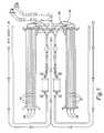
- FIG. 3is a schematic illustration of a preferred form of air conditioning system for busses
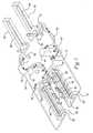
- FIG. 4is a perspective view of the preferred form of air conditioning system for busses including a pair of roof-mounted compressors between the evaporator and condenser sections of the system;
- FIG. 5is a plan view in more detail of the refrigerant supply lines into each of the evaporator sections of the system shown in FIGS. 3 and 4;
- FIG. 6is an end view of the evaporator sections shown in FIG. 6 .
- FIGS. 1 and 2A prior art air conditioning system for busses is schematically shown in FIGS. 1 and 2 in which FREON® or other refrigerant in its gaseous state is drawn from evaporator coils 10 through a suction line 12 into compressor 14 which is driven off of a bus engine M.
- the cool FREON® gasundergoes both an increase in temperature and pressure and is then discharged by the compressor through line 16 into condenser coils 18 .
- the gascirculates internally through the coils 18 , ambient air is drawn through the coil fins by a combination of centrally located condenser fans F and side air inlets I, as shown in FIG. 2 .
- the FREON® gasis liquefied as the air is drawn across the condenser coils 18 and by the increased pressure of the gas created by the compressor 14 . Any heat given up by the gas in its conversion into liquid form is expelled by the condenser fans F.
- The, liquid refrigerant from the condenser coils 18is delivered into a receiver/dryer 24 via the refrigerant lines 23 from the condenser coils 18 .
- the refrigerantthen advances into the evaporator section 10 via liquid line 26 which is attached to the expansion valve 27 , the latter controlling the amount of liquid FREON® entering the two evaporator coils 10 for coolant vaporization.
- Expansion valve 27opens and closes in accordance with the temperature and pressure at the evaporator outlet so as to control the amount of FREON® entering the evaporator coils.
- the FREON®enters the coils 10 through inlet lines 28 so as to insure that the FREON® is distributed evenly within the coils 10 .
- the receiver/dryer 24acts as a cooling chamber for the hot liquid refrigerant as well as a mixing chamber for oil and refrigerant.
- the refrigerant 24is stored in the receiver until needed by the evaporators while being filtered and any moisture dried from the system.
- the expansion valve 27controls the amount of liquid FREON® admitted to the evaporator coils 10 via branch lines 28 , and the internal pressure of the coils 10 is reduced causing the FREON® to absorb heat from the air passing over the evaporator coils 10 as it is vaporized.
- the refrigerant gasis then returned to the compressor 14 via suction line 12 to repeat the cycle as described.
- the air movement across the evaporator coils 10is controlled by evaporator blowers B outboard of the coils and which communicate with air circulating ducts D along opposite sides of the bus and leading into the bus interior, as shown in FIG. 2 .
- Representative of such a circulating systemis that illustrated and described in U.S. Pat. No. 4,607,497 entitled ROOF-MOUNTED AIR CONDITIONER SYSTEM HAVING MODULAR EVAPORATOR AND CONDENSOR UNITS and U.S. Pat. No. 5,184,474 for ROOF-MOUNTED AIR CONDITIONING SYSTEM WITH BUILT-IN COMPRESSOR, both assigned to the assignee of this invention.
- the compressorshould become overloaded or break down, the interior of the bus will be completely deprived of conditioned air.
- the preferred form illustrated in FIG. 3operates as in the prior art version of FIGS. 1 and 2 to deliver refrigerant in vaporized form from evaporator coils to be described through separate suction lines 42 into a pair of compressors 44 .
- the relatively low temperature refrigerant gasundergoes an increase in temperature and pressure prior to discharge through lines 46 leading to each of a pair of condenser coils 48 in condensor unit 49 .
- the high pressure vaporcirculates through the coils 48 , ambient air is drawn across the coil fins by a combination of the centrally located condenser fans F and side air inlets I as illustrated in FIG. 2 .
- the refrigerant gasis condensed as a result of the reduction in temperature caused by passage of the air across the condenser coils 48 as well as the increased pressure of the vapor created by the compressors 44 .
- the liquid refrigerant from the coils 48is delivered into receiver tanks 50 through discharge lines 51 leading from each condenser.
- the refrigerantis then delivered from the receiver tanks 50 through separate delivery lines 54 , each of the lines 54 provided with conventional filter dryer 55 , sight glass 56 , solenoid valve 57 and expansion valve 58 .
- the expansion valve 58 in each line 54opens and closes in accordance with the temperature and pressure at the evaporator outlet so as to control the amount of refrigerant entering the evaporator sections.
- capillary tubesdefine branch lines 59 and 60 which extend from each of the refrigerant lines 54 at the outlet sides of the expansion valves 58 into one or more evaporator coil 62 or 62 ′ in one evaporator section 64 , and coils 63 or 63 ′ in the second evaporator section 65 .
- the evaporator blowers Bserve to draw air across the evaporator coils 62 , 62 ′ and 63 , 63 ′ resulting in an increase in temperature of the refrigerant sufficient to cause it to vaporize and cool the air circulating thereacross prior to entry through the air circulating ducts D.
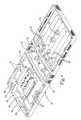
- each of the evaporator coils 62 , 62 ′ and 63 , 63 ′is mounted for extension lengthwise through a series of fins which make up the respective elongated evaporator sections 64 and 65 so as to promote maximum exposure to the air and most effective cooling of the air prior to circulation into the interior of the bus.
- each of the coils 62 and 63 in a respective evaporator section 64 and 65is connected via branch lines 59 to one of the condenser sections 49
- each of the coils 62 ′ and 63 ′is connected via branch lines 60 to the condenser unit 49 for the other compressor.
- each coil 62 , 62 ′ and 63 , 63 ′is comprised of longitudinally extending straight tubes 67 arranged in spaced parallel relation across the width of each evaporator section and interconnected by generally U-shaped returns 68 , and the innermost returns 68 terminate in manifolds 69 in accordance with well-known practice and then returns to their respective compressor 44 via the return lines 42 .
- scroll or piston compressorsare utilized.
- a pair of 5 ton scroll compressors each with a built-in motorwould be utilized to take the place of a single 10 ton compressor.
- different size or load compressorsmay be employed, such as, for example, 2.5 ton, 6 or 7.5 ton depending upon cooling requirements.
- each of the expansion valves 58opens and closes in accordance with the temperature and pressure at the evaporator outlet so as to control the amount of refrigerant entering the evaporator coils 62 , 62 ′ and 63 , 63 ′.
- Each dryer 55operates as a drying and cleaning chamber for the liquid refrigerant from the condensors as well as a mixing chamber for oil and refrigerant.
- the expansion valves 58also control the amount of liquid refrigerant admitted to the evaporator coils 62 , 62 ′ and 63 , 63 ′, and the internal pressure of the refrigerant is reduced so as to absorb heat from the air passing over the coils as it is vaporized.
- the compressors 44are powered by a single generator G which is driven off of the engine M. If there is insufficient power generated by the generator G to run both compressors 44 , only one of the compressors is operated at a reduced power level to that of both compressors but will nevertheless continue to supply conditioned air through both evaporator sections 64 and 65 from the single compressor. This is in contradistinction to the single loop system in which each refrigerant line from the condenser circulates refrigerant only through one evaporator section.
- a switch port S as shown in FIG. 2is provided with a power cord C which enables plug-in to an electrical outlet for auxiliary power to initiate start-up of the air comfort system and thereby avoid using fuel during the start-up period prior to actual starting of the bus.
- the switch portswill then enable switching over to the generator once the bus interior is cooled to the desired temperature level in order to start up the bus.
- a roof-mounted air conditioning system 70includes a built-in compressor compartment 72 containing a pair of compressors 73 in juxtaposed relation to one another between the condenser section 74 and evaporator section 76 .
- Fans 78 in the condenser section 74induce the flow of air through the compressor compartment 72 and into the condenser section 74 through vents 80 in opposite side walls of the compressor compartment 72 as well as additional vents 81 in a partition wall between the compressor section 72 and condensor section 74 .
- the air directed into the compressor compartment 72will flow directly across the condenser coils 75 in the condenser section 74 and through discharge openings, not shown, in the cover of the condenser section 74 .
- the vents 81 in the partition wallmay be louvered in order to regulate the relative amount of air drawn through the air intake grilles 80 to the total air flow so as to avoid forcing too much air and moisture over the compressor motors.
- the refrigeration cycleis identical to that described and shown in FIG. 3 .
- electrical heaters 84extend along opposite sides of the evaporator sections 64 and 65 to heat the air that is drawn across the evaporator sections by the blowers B for circulation into the bus interior.
- the twin compressors 73offer a unique ability to gradually cool the air circulated by successive activation of the compressors 73 as the temperature increases above the set point. For example, assuming that the set point is established at 68° F. and the temperature in the bus interior should increase slightly above the set point, only one of the compressors 73 need be activated to reduce the temperature. If the temperature increase is more substantial then of course both compressors 73 would be activated.
Landscapes
- Physics & Mathematics (AREA)
- Thermal Sciences (AREA)
- Engineering & Computer Science (AREA)
- Mechanical Engineering (AREA)
- Air-Conditioning For Vehicles (AREA)
Abstract
Description
Claims (21)
Priority Applications (1)
| Application Number | Priority Date | Filing Date | Title |
|---|---|---|---|
| US09/686,176US6415620B1 (en) | 2000-10-12 | 2000-10-12 | Dual loop vehicle air conditioning system |
Applications Claiming Priority (1)
| Application Number | Priority Date | Filing Date | Title |
|---|---|---|---|
| US09/686,176US6415620B1 (en) | 2000-10-12 | 2000-10-12 | Dual loop vehicle air conditioning system |
Publications (1)
| Publication Number | Publication Date |
|---|---|
| US6415620B1true US6415620B1 (en) | 2002-07-09 |
Family
ID=24755229
Family Applications (1)
| Application Number | Title | Priority Date | Filing Date |
|---|---|---|---|
| US09/686,176Expired - LifetimeUS6415620B1 (en) | 2000-10-12 | 2000-10-12 | Dual loop vehicle air conditioning system |
Country Status (1)
| Country | Link |
|---|---|
| US (1) | US6415620B1 (en) |
Cited By (32)
| Publication number | Priority date | Publication date | Assignee | Title |
|---|---|---|---|---|
| US20030233840A1 (en)* | 2002-06-25 | 2003-12-25 | Kwang-Yong Choi | Hybrid air-conditioning system and method thereof for hybrid electric vehicle |
| US6763668B1 (en)* | 2003-05-05 | 2004-07-20 | Carrier Corporation | Unibody modular bus air conditioner |
| US6763670B1 (en)* | 2003-05-05 | 2004-07-20 | Carrier Corporation | Configuration for modular rooftop air conditioning system |
| US6796132B1 (en)* | 2003-05-05 | 2004-09-28 | Carrier Corporation | Method and apparatus for refreshing air in a bustop air conditioner |
| US20040221599A1 (en)* | 2003-05-05 | 2004-11-11 | Carrier Corporation | Horizontal rotary compressor in a bus air conditioner |
| US20050034470A1 (en)* | 2003-05-05 | 2005-02-17 | Carrier Corporation | Modular bus air conditioning system |
| US20050155375A1 (en)* | 2004-01-16 | 2005-07-21 | Wensink Theodore C. | Dual-circuit refrigeration system |
| WO2006021226A1 (en)* | 2004-08-26 | 2006-03-02 | Dometic Wta S.R.L. | Method for operating an air-conditioning unit and corresponding device |
| US20060086121A1 (en)* | 2002-02-11 | 2006-04-27 | Wiggs B R | Capillary tube/plate refrigerant/air heat exchanger for use in conjunction with a method and apparatus for inhibiting ice accumulation in HVAC systems |
| US20070033954A1 (en)* | 2005-08-10 | 2007-02-15 | Lg Electronics Inc. | Driving controlling apparatus for air conditioner having plural compressors and method thereof |
| US20070215398A1 (en)* | 2006-03-15 | 2007-09-20 | Ferdows Houshang K | Modular roof-mounted radiator compartment and other roof-mounted utility compartments for buses |
| US20080029241A1 (en)* | 2006-08-01 | 2008-02-07 | Rayco Manufacturing, Inc. | Off-road equipment with elevated cooling boxes |
| DE202007007103U1 (en)* | 2007-05-18 | 2008-09-25 | Thermo King Deutschland Gmbh | On-roof air conditioner for a vehicle, in particular a bus |
| DE102007023249A1 (en)* | 2007-05-18 | 2008-11-20 | Thermo King Deutschland Gmbh | Roof-mounted air conditioning system for omnibus or tram is a pre-assembled modular unit |
| US20100031686A1 (en)* | 2008-05-15 | 2010-02-11 | Multistack Llc | Modular outboard heat exchanger air conditioning system |
| WO2011055163A1 (en)* | 2009-11-09 | 2011-05-12 | Carlos Quesada Saborio | Transport refrigeration system |
| US8650895B2 (en) | 2012-01-25 | 2014-02-18 | Thermo King Corporation | Method for constructing air conditioning systems with universal base units |
| US9272600B2 (en) | 2009-02-27 | 2016-03-01 | Thermo King Corporation | Low profile air conditioning unit for vehicles |
| DE102015211606A1 (en)* | 2015-06-23 | 2016-12-29 | Mahle International Gmbh | Evaporator unit for a rooftop air conditioning system of a road vehicle |
| US9746209B2 (en) | 2014-03-14 | 2017-08-29 | Hussman Corporation | Modular low charge hydrocarbon refrigeration system and method of operation |
| WO2017162237A1 (en)* | 2016-03-24 | 2017-09-28 | Benteler Automobiltechnik Gmbh | Heating device and method for heating a motor vehicle |
| US20180015809A1 (en)* | 2016-07-15 | 2018-01-18 | TransArctic Canada, Inc. | Adaptable roof-mounted air conditioning system for vehicles |
| CN107891727A (en)* | 2017-10-20 | 2018-04-10 | 广东劲达制冷集团有限公司 | Building blocks combined type New energy electric coach air conditioner unit |
| CN109515119A (en)* | 2018-11-06 | 2019-03-26 | 珠海格力电器股份有限公司 | Vehicle with a steering wheel |
| CN109720171A (en)* | 2019-03-04 | 2019-05-07 | 湖北美标汽车制冷系统有限公司 | Double-compressor and the heavy truck air-conditioning system of double steamings |
| US20190160909A1 (en)* | 2017-11-24 | 2019-05-30 | Hanon Systems | Multi-zone air conditioning system for vehicles |
| EA036187B1 (en)* | 2019-08-06 | 2020-10-12 | Алексей Сергеевич ЗАКАТОВ | Roof air conditioner for multi-car single-compartment rail vehicle |
| US11529840B2 (en) | 2019-06-28 | 2022-12-20 | Toyota Jidosha Kabushiki Kaisha | Vehicle air conditioner |
| US11554641B2 (en) | 2019-06-28 | 2023-01-17 | Toyota Jidosha Kabushiki Kaisha | Vehicle air conditioner |
| US11679647B2 (en) | 2019-06-28 | 2023-06-20 | Toyota Jidosha Kabushiki Kaisha | Vehicle air conditioner and vehicle |
| US11707965B2 (en)* | 2019-06-12 | 2023-07-25 | Haier Us Appliance Solutions, Inc. | Baffle assembly for vehicular air conditioner |
| US20250010688A1 (en)* | 2023-07-03 | 2025-01-09 | Hyundai Motor Company | Air conditioning system for mobility vehicle |
Citations (8)
| Publication number | Priority date | Publication date | Assignee | Title |
|---|---|---|---|---|
| US2062054A (en)* | 1935-04-26 | 1936-11-24 | Westinghouse Electric & Mfg Co | Air conditioning apparatus |
| US2155484A (en)* | 1935-01-12 | 1939-04-25 | Westinghouse Electric & Mfg Co | Air conditioning apparatus |
| US3402564A (en)* | 1967-03-06 | 1968-09-24 | Larkin Coils Inc | Air conditioning system having reheating with compressor discharge gas |
| US3545222A (en)* | 1968-10-14 | 1970-12-08 | Trane Co | Dual powered refrigeration system |
| US4318278A (en)* | 1978-07-03 | 1982-03-09 | King-Seeley Thermos Co. | Ice making machine |
| US4607497A (en) | 1983-12-20 | 1986-08-26 | Suetrak U.S.A. | Roof-mounted air conditioner system having modular evaporator and condensor units |
| US5184474A (en) | 1991-11-15 | 1993-02-09 | Suetrak Air Conditioning Sales Corp. | Roof-mounted air conditioning system with built-in compressor |
| US5867996A (en)* | 1997-02-24 | 1999-02-09 | Denso Corporation | Compressor control device for vehicle air conditioner |
- 2000
- 2000-10-12USUS09/686,176patent/US6415620B1/ennot_activeExpired - Lifetime
Patent Citations (8)
| Publication number | Priority date | Publication date | Assignee | Title |
|---|---|---|---|---|
| US2155484A (en)* | 1935-01-12 | 1939-04-25 | Westinghouse Electric & Mfg Co | Air conditioning apparatus |
| US2062054A (en)* | 1935-04-26 | 1936-11-24 | Westinghouse Electric & Mfg Co | Air conditioning apparatus |
| US3402564A (en)* | 1967-03-06 | 1968-09-24 | Larkin Coils Inc | Air conditioning system having reheating with compressor discharge gas |
| US3545222A (en)* | 1968-10-14 | 1970-12-08 | Trane Co | Dual powered refrigeration system |
| US4318278A (en)* | 1978-07-03 | 1982-03-09 | King-Seeley Thermos Co. | Ice making machine |
| US4607497A (en) | 1983-12-20 | 1986-08-26 | Suetrak U.S.A. | Roof-mounted air conditioner system having modular evaporator and condensor units |
| US5184474A (en) | 1991-11-15 | 1993-02-09 | Suetrak Air Conditioning Sales Corp. | Roof-mounted air conditioning system with built-in compressor |
| US5867996A (en)* | 1997-02-24 | 1999-02-09 | Denso Corporation | Compressor control device for vehicle air conditioner |
Cited By (47)
| Publication number | Priority date | Publication date | Assignee | Title |
|---|---|---|---|---|
| US20060086121A1 (en)* | 2002-02-11 | 2006-04-27 | Wiggs B R | Capillary tube/plate refrigerant/air heat exchanger for use in conjunction with a method and apparatus for inhibiting ice accumulation in HVAC systems |
| US20030233840A1 (en)* | 2002-06-25 | 2003-12-25 | Kwang-Yong Choi | Hybrid air-conditioning system and method thereof for hybrid electric vehicle |
| US6748750B2 (en)* | 2002-06-25 | 2004-06-15 | Hyundai Motor Company | Hybrid air-conditioning system and method thereof for hybrid electric vehicle |
| US20050034470A1 (en)* | 2003-05-05 | 2005-02-17 | Carrier Corporation | Modular bus air conditioning system |
| US6796132B1 (en)* | 2003-05-05 | 2004-09-28 | Carrier Corporation | Method and apparatus for refreshing air in a bustop air conditioner |
| US20040221599A1 (en)* | 2003-05-05 | 2004-11-11 | Carrier Corporation | Horizontal rotary compressor in a bus air conditioner |
| US6915651B2 (en)* | 2003-05-05 | 2005-07-12 | Carrier Corporation | Horizontal rotary compressor in a bus air conditioner |
| US6763670B1 (en)* | 2003-05-05 | 2004-07-20 | Carrier Corporation | Configuration for modular rooftop air conditioning system |
| US6763668B1 (en)* | 2003-05-05 | 2004-07-20 | Carrier Corporation | Unibody modular bus air conditioner |
| US7051544B2 (en)* | 2003-05-05 | 2006-05-30 | Carrier Corporation | Modular bus air conditioning system |
| US20050155375A1 (en)* | 2004-01-16 | 2005-07-21 | Wensink Theodore C. | Dual-circuit refrigeration system |
| US6978630B2 (en) | 2004-01-16 | 2005-12-27 | Dometic Corporation | Dual-circuit refrigeration system |
| WO2006017060A3 (en)* | 2004-07-09 | 2006-06-08 | Carrier Corp | Modular bus air conditioning system |
| WO2006021226A1 (en)* | 2004-08-26 | 2006-03-02 | Dometic Wta S.R.L. | Method for operating an air-conditioning unit and corresponding device |
| US20070033954A1 (en)* | 2005-08-10 | 2007-02-15 | Lg Electronics Inc. | Driving controlling apparatus for air conditioner having plural compressors and method thereof |
| US20070215398A1 (en)* | 2006-03-15 | 2007-09-20 | Ferdows Houshang K | Modular roof-mounted radiator compartment and other roof-mounted utility compartments for buses |
| US7571785B2 (en) | 2006-03-15 | 2009-08-11 | Ferdows Houshang K | Modular roof-mounted radiator compartment and other roof-mounted utility compartments for buses |
| US20080029241A1 (en)* | 2006-08-01 | 2008-02-07 | Rayco Manufacturing, Inc. | Off-road equipment with elevated cooling boxes |
| DE202007007103U1 (en)* | 2007-05-18 | 2008-09-25 | Thermo King Deutschland Gmbh | On-roof air conditioner for a vehicle, in particular a bus |
| DE102007023249A1 (en)* | 2007-05-18 | 2008-11-20 | Thermo King Deutschland Gmbh | Roof-mounted air conditioning system for omnibus or tram is a pre-assembled modular unit |
| DE102007023249B4 (en)* | 2007-05-18 | 2014-02-13 | Ingersoll-Rand Klimasysteme Deutschland Gmbh | On-roof air conditioner for a vehicle, in particular a bus |
| US8627674B2 (en)* | 2008-05-15 | 2014-01-14 | Mark PLATT | Modular outboard heat exchanger air conditioning system |
| US20100031686A1 (en)* | 2008-05-15 | 2010-02-11 | Multistack Llc | Modular outboard heat exchanger air conditioning system |
| US9272600B2 (en) | 2009-02-27 | 2016-03-01 | Thermo King Corporation | Low profile air conditioning unit for vehicles |
| WO2011055163A1 (en)* | 2009-11-09 | 2011-05-12 | Carlos Quesada Saborio | Transport refrigeration system |
| US8650895B2 (en) | 2012-01-25 | 2014-02-18 | Thermo King Corporation | Method for constructing air conditioning systems with universal base units |
| US9746209B2 (en) | 2014-03-14 | 2017-08-29 | Hussman Corporation | Modular low charge hydrocarbon refrigeration system and method of operation |
| DE102015211606A1 (en)* | 2015-06-23 | 2016-12-29 | Mahle International Gmbh | Evaporator unit for a rooftop air conditioning system of a road vehicle |
| US10675949B2 (en)* | 2015-06-23 | 2020-06-09 | Mahle International Gmbh | Evaporator unit for a rooftop air-conditioning system of a road-going vehicle |
| WO2017162237A1 (en)* | 2016-03-24 | 2017-09-28 | Benteler Automobiltechnik Gmbh | Heating device and method for heating a motor vehicle |
| US10391840B2 (en)* | 2016-07-15 | 2019-08-27 | TransArctic Canada, Inc. | Adaptable roof-mounted air conditioning system for vehicles |
| US20180015809A1 (en)* | 2016-07-15 | 2018-01-18 | TransArctic Canada, Inc. | Adaptable roof-mounted air conditioning system for vehicles |
| CN107891727A (en)* | 2017-10-20 | 2018-04-10 | 广东劲达制冷集团有限公司 | Building blocks combined type New energy electric coach air conditioner unit |
| CN107891727B (en)* | 2017-10-20 | 2024-01-19 | 浙江纵驰环境科技有限公司 | Building block combined new energy electric bus air conditioning unit |
| US11104201B2 (en)* | 2017-11-24 | 2021-08-31 | Hanon Systems | Multi-zone air conditioning system for vehicles |
| US20190160909A1 (en)* | 2017-11-24 | 2019-05-30 | Hanon Systems | Multi-zone air conditioning system for vehicles |
| CN109515119A (en)* | 2018-11-06 | 2019-03-26 | 珠海格力电器股份有限公司 | Vehicle with a steering wheel |
| CN109720171B (en)* | 2019-03-04 | 2024-01-26 | 湖北美标汽车制冷系统有限公司 | Double-compressor and double-steaming heavy-duty truck air conditioning system |
| CN109720171A (en)* | 2019-03-04 | 2019-05-07 | 湖北美标汽车制冷系统有限公司 | Double-compressor and the heavy truck air-conditioning system of double steamings |
| US11707965B2 (en)* | 2019-06-12 | 2023-07-25 | Haier Us Appliance Solutions, Inc. | Baffle assembly for vehicular air conditioner |
| US11529840B2 (en) | 2019-06-28 | 2022-12-20 | Toyota Jidosha Kabushiki Kaisha | Vehicle air conditioner |
| US11554641B2 (en) | 2019-06-28 | 2023-01-17 | Toyota Jidosha Kabushiki Kaisha | Vehicle air conditioner |
| US11679647B2 (en) | 2019-06-28 | 2023-06-20 | Toyota Jidosha Kabushiki Kaisha | Vehicle air conditioner and vehicle |
| DE102020116502B4 (en) | 2019-06-28 | 2024-10-17 | Toyota Jidosha Kabushiki Kaisha | vehicle air conditioning system |
| DE102020116207B4 (en)* | 2019-06-28 | 2025-03-13 | Toyota Jidosha Kabushiki Kaisha | Electric vehicle with air conditioning |
| EA036187B1 (en)* | 2019-08-06 | 2020-10-12 | Алексей Сергеевич ЗАКАТОВ | Roof air conditioner for multi-car single-compartment rail vehicle |
| US20250010688A1 (en)* | 2023-07-03 | 2025-01-09 | Hyundai Motor Company | Air conditioning system for mobility vehicle |
Similar Documents
| Publication | Publication Date | Title |
|---|---|---|
| US6415620B1 (en) | Dual loop vehicle air conditioning system | |
| US10953727B2 (en) | Air-conditioning system of a motor vehicle and method for operating the air-conditioning system | |
| US10821801B2 (en) | Air conditioner for vehicle | |
| US10875385B2 (en) | Climate control system of a motor vehicle and method for operating the climate control system | |
| US11413931B2 (en) | Vehicle-mounted temperature controller | |
| JP4587108B2 (en) | Vehicle air conditioning unit and method of using the same | |
| US11724570B2 (en) | Vehicle-mounted temperature control system | |
| US6640889B1 (en) | Dual loop heat and air conditioning system | |
| US10987997B2 (en) | Air conditioning system of a motor vehicle and method for operating the air conditioning system | |
| US6769481B2 (en) | Outdoor heat exchanger unit, outdoor unit, and gas heat pump type air conditioner | |
| US6862892B1 (en) | Heat pump and air conditioning system for a vehicle | |
| US6708513B2 (en) | CO2-module for cooling and heating | |
| US4523437A (en) | Vehicle air conditioning system | |
| US20180319254A1 (en) | Air conditioning system of a motor vehicle and method for operating the air conditioning system | |
| CN103270377A (en) | Heat exchange system | |
| KR102266483B1 (en) | Heat exchanger arrangement for an air conditioning system and air conditioning system of a motor vehicle and method for operating the air conditioning system | |
| US4384608A (en) | Reverse cycle air conditioner system | |
| KR20210114344A (en) | In-vehicle temperature control system | |
| KR20140126846A (en) | Heat pump system for vehicle | |
| KR20170094015A (en) | Thermal management system of battery for vehicle | |
| US20010001982A1 (en) | Heating and air conditioning unit of a motor vehicle | |
| CN114364553B (en) | Method for thermal management of a motor vehicle | |
| CN116552198B (en) | A thermal management system for pure electric vehicles | |
| US6739148B2 (en) | Temperature control system for a vehicle | |
| JP2555197Y2 (en) | Automotive air conditioners |
Legal Events
| Date | Code | Title | Description |
|---|---|---|---|
| FPAY | Fee payment | Year of fee payment:4 | |
| FEPP | Fee payment procedure | Free format text:PAYER NUMBER DE-ASSIGNED (ORIGINAL EVENT CODE: RMPN); ENTITY STATUS OF PATENT OWNER: SMALL ENTITY Free format text:PAYOR NUMBER ASSIGNED (ORIGINAL EVENT CODE: ASPN); ENTITY STATUS OF PATENT OWNER: SMALL ENTITY | |
| FPAY | Fee payment | Year of fee payment:8 | |
| FEPP | Fee payment procedure | Free format text:PAYOR NUMBER ASSIGNED (ORIGINAL EVENT CODE: ASPN); ENTITY STATUS OF PATENT OWNER: SMALL ENTITY Free format text:PAYER NUMBER DE-ASSIGNED (ORIGINAL EVENT CODE: RMPN); ENTITY STATUS OF PATENT OWNER: SMALL ENTITY | |
| REMI | Maintenance fee reminder mailed | ||
| LAPS | Lapse for failure to pay maintenance fees | ||
| REIN | Reinstatement after maintenance fee payment confirmed | ||
| FP | Lapsed due to failure to pay maintenance fee | Effective date:20140709 | |
| FEPP | Fee payment procedure | Free format text:PETITION RELATED TO MAINTENANCE FEES FILED (ORIGINAL EVENT CODE: PMFP); ENTITY STATUS OF PATENT OWNER: SMALL ENTITY | |
| FPAY | Fee payment | Year of fee payment:12 | |
| SULP | Surcharge for late payment | ||
| FEPP | Fee payment procedure | Free format text:PETITION RELATED TO MAINTENANCE FEES GRANTED (ORIGINAL EVENT CODE: PMFG); ENTITY STATUS OF PATENT OWNER: SMALL ENTITY | |
| PRDP | Patent reinstated due to the acceptance of a late maintenance fee | Effective date:20170703 | |
| STCF | Information on status: patent grant | Free format text:PATENTED CASE |